EP3492163B1 - Labor-saving paint mixing cover - Google Patents
Labor-saving paint mixing cover Download PDFInfo
- Publication number
- EP3492163B1 EP3492163B1 EP17833524.6A EP17833524A EP3492163B1 EP 3492163 B1 EP3492163 B1 EP 3492163B1 EP 17833524 A EP17833524 A EP 17833524A EP 3492163 B1 EP3492163 B1 EP 3492163B1
- Authority
- EP
- European Patent Office
- Prior art keywords
- pressing
- pressing rod
- cam
- movable pipe
- presser foot
- Prior art date
- Legal status (The legal status is an assumption and is not a legal conclusion. Google has not performed a legal analysis and makes no representation as to the accuracy of the status listed.)
- Active
Links
Images
Classifications
-
- B—PERFORMING OPERATIONS; TRANSPORTING
- B01—PHYSICAL OR CHEMICAL PROCESSES OR APPARATUS IN GENERAL
- B01F—MIXING, e.g. DISSOLVING, EMULSIFYING OR DISPERSING
- B01F35/00—Accessories for mixers; Auxiliary operations or auxiliary devices; Parts or details of general application
- B01F35/45—Closures or doors specially adapted for mixing receptacles; Operating mechanisms therefor
-
- B—PERFORMING OPERATIONS; TRANSPORTING
- B44—DECORATIVE ARTS
- B44D—PAINTING OR ARTISTIC DRAWING, NOT OTHERWISE PROVIDED FOR; PRESERVING PAINTINGS; SURFACE TREATMENT TO OBTAIN SPECIAL ARTISTIC SURFACE EFFECTS OR FINISHES
- B44D3/00—Accessories or implements for use in connection with painting or artistic drawing, not otherwise provided for; Methods or devices for colour determination, selection, or synthesis, e.g. use of colour tables
- B44D3/12—Paint cans; Brush holders; Containers for storing residual paint
- B44D3/127—Covers or lids for paint cans
-
- B—PERFORMING OPERATIONS; TRANSPORTING
- B01—PHYSICAL OR CHEMICAL PROCESSES OR APPARATUS IN GENERAL
- B01F—MIXING, e.g. DISSOLVING, EMULSIFYING OR DISPERSING
- B01F27/00—Mixers with rotary stirring devices in fixed receptacles; Kneaders
-
- B—PERFORMING OPERATIONS; TRANSPORTING
- B01—PHYSICAL OR CHEMICAL PROCESSES OR APPARATUS IN GENERAL
- B01F—MIXING, e.g. DISSOLVING, EMULSIFYING OR DISPERSING
- B01F27/00—Mixers with rotary stirring devices in fixed receptacles; Kneaders
- B01F27/80—Mixers with rotary stirring devices in fixed receptacles; Kneaders with stirrers rotating about a substantially vertical axis
- B01F27/90—Mixers with rotary stirring devices in fixed receptacles; Kneaders with stirrers rotating about a substantially vertical axis with paddles or arms
-
- B—PERFORMING OPERATIONS; TRANSPORTING
- B01—PHYSICAL OR CHEMICAL PROCESSES OR APPARATUS IN GENERAL
- B01F—MIXING, e.g. DISSOLVING, EMULSIFYING OR DISPERSING
- B01F35/00—Accessories for mixers; Auxiliary operations or auxiliary devices; Parts or details of general application
- B01F35/45—Closures or doors specially adapted for mixing receptacles; Operating mechanisms therefor
- B01F35/453—Closures or doors specially adapted for mixing receptacles; Operating mechanisms therefor by moving them perpendicular to the plane of the opening
-
- B—PERFORMING OPERATIONS; TRANSPORTING
- B44—DECORATIVE ARTS
- B44D—PAINTING OR ARTISTIC DRAWING, NOT OTHERWISE PROVIDED FOR; PRESERVING PAINTINGS; SURFACE TREATMENT TO OBTAIN SPECIAL ARTISTIC SURFACE EFFECTS OR FINISHES
- B44D3/00—Accessories or implements for use in connection with painting or artistic drawing, not otherwise provided for; Methods or devices for colour determination, selection, or synthesis, e.g. use of colour tables
- B44D3/06—Implements for stirring or mixing paints
- B44D3/08—Implements for stirring or mixing paints for liquid or semi-liquid paints
-
- B—PERFORMING OPERATIONS; TRANSPORTING
- B44—DECORATIVE ARTS
- B44D—PAINTING OR ARTISTIC DRAWING, NOT OTHERWISE PROVIDED FOR; PRESERVING PAINTINGS; SURFACE TREATMENT TO OBTAIN SPECIAL ARTISTIC SURFACE EFFECTS OR FINISHES
- B44D3/00—Accessories or implements for use in connection with painting or artistic drawing, not otherwise provided for; Methods or devices for colour determination, selection, or synthesis, e.g. use of colour tables
- B44D3/12—Paint cans; Brush holders; Containers for storing residual paint
-
- B—PERFORMING OPERATIONS; TRANSPORTING
- B65—CONVEYING; PACKING; STORING; HANDLING THIN OR FILAMENTARY MATERIAL
- B65D—CONTAINERS FOR STORAGE OR TRANSPORT OF ARTICLES OR MATERIALS, e.g. BAGS, BARRELS, BOTTLES, BOXES, CANS, CARTONS, CRATES, DRUMS, JARS, TANKS, HOPPERS, FORWARDING CONTAINERS; ACCESSORIES, CLOSURES, OR FITTINGS THEREFOR; PACKAGING ELEMENTS; PACKAGES
- B65D51/00—Closures not otherwise provided for
- B65D51/14—Rigid discs or spherical members adapted to be held in sealing engagement with mouth of container, e.g. closure plates for preserving jars
-
- B—PERFORMING OPERATIONS; TRANSPORTING
- B01—PHYSICAL OR CHEMICAL PROCESSES OR APPARATUS IN GENERAL
- B01F—MIXING, e.g. DISSOLVING, EMULSIFYING OR DISPERSING
- B01F35/00—Accessories for mixers; Auxiliary operations or auxiliary devices; Parts or details of general application
- B01F35/30—Driving arrangements; Transmissions; Couplings; Brakes
- B01F2035/35—Use of other general mechanical engineering elements in mixing devices
- B01F2035/351—Sealings
-
- B—PERFORMING OPERATIONS; TRANSPORTING
- B01—PHYSICAL OR CHEMICAL PROCESSES OR APPARATUS IN GENERAL
- B01F—MIXING, e.g. DISSOLVING, EMULSIFYING OR DISPERSING
- B01F2101/00—Mixing characterised by the nature of the mixed materials or by the application field
- B01F2101/30—Mixing paints or paint ingredients, e.g. pigments, dyes, colours, lacquers or enamel
Definitions
- the present invention relates to a canister lid for a paint mixing stirrer.
- the canister lid can be clamped on and cover a paint bucket and achieve control of colored paint stirring and the pouring-out quantity of a colored paint.
- United States Patent N° 2,585,334 discloses a closure for paint cans.
- a paint mixing stirrer is common equipment in the automobile repair industry.
- a canister lid for a paint bucket uses a knob wrench thereon to clamp a presser foot onto the paint bucket, and then they are placed on the paint mixing stirrer, which rotates blades of the canister lid, to achieve stirring of a colored paint in the colored paint bucket.
- a patent entitled "Canister lid of colored paint bucket with anti-drop pressure lever fixing seat” discloses a canister lid of a colored paint bucket, which is very good in the control of paint mixing and pouring-out quantity, wherein the lid of the paint container has both functions of sealing the container and precisely controlling the pouring-out flow.
- a canister lid body is provided with a paint outlet mechanism, including an outlet on the lid body for pouring out the contained substance, wherein the outlet is covered with a slidable covering plate with a sealing function.
- the covering plate is connected to a manual press wrench through a resilient U-shaped torsional spring. When the container is inclined and the wrench is pressed, the slidable covering plate can be opened.
- the outlet of the lid is opened, and the contained substance (i.e. liquid paint) flows out from a liquid pouring port.
- the angle of the press wrench can control the stroke of the slidable covering plate, so that the covering plate and the lid outlet are opened a controlled outlet size to control the pouring-out flow.
- a gas intake hole is formed on the other side of the pouring-out port, so that during the pouring-out process, air can enter the closed container with the pouring out of the poured-out substance. In this way, the contained substance is poured out smoothly.
- the gas inlet hole is closed by a tapered plug fixed on the wrench when the contained substance is not poured out from the canister lid.
- the gas inlet hole is opened only when the covering plate is opened by the press wrench to pour out the contained substance.
- the canister lid body is further provided with a pressing mechanism, including a through hole formed on the canister lid, wherein a seal sleeve is arranged in the through hole; a pressing lever is arranged in the seal sleeve; a handle is provided on the upper end of the pressing lever; a spring is sleeved outside the pressing lever between the seal sleeve and the handle; and a presser foot is provided at the lower end of the pressing lever.
- the handle needs to be pressed down manually with force and fixed, so that the spring is pressed to retain a space for cooperation between the presser foot and the paint bucket. Then the handle is rotated, so that the presser foot moves to a location below the paint bucket opening. Finally, the handle is released by the hand, the spring is reset, and the presser foot clamps the colored paint bucket opening, thus completing the assembly.
- the knob when the canister lid is compressed, the knob also needs to be pressed and rotated to ensure the presser foot is clamped on the paint bucket. Often, to ensure the sealing performance of the canister lid, the compressed spring of the knob is designed to have great elasticity. When the knob is rotated, the compressed spring needs to be pressed continuously. This can generate a very large counteracting force on the finger. The hand is squeezed and the operation is strenuous, and a person feels very uncomfortable in the case of repeated installation.
- the present invention needs to solve the present technical problem of being very strenuous.
- a technical solution of the present invention is specifically: a stirring canister lid adapted to different paint bucket openings, comprising a paint outlet mechanism for controlling a paint to be poured out, and at least two pressing mechanisms for pressing a paint bucket and the canister lid, wherein for each pressing mechanism, the canister lid is provided with a through hole; a pressing rod penetrates through the through hole; a seal sleeve is sleeved outside the pressing rod; a seal sleeve flange of the seal sleeve is pressed against the canister lid; a compressed spring is sleeved at the outer periphery of the pressing rod between the seal sleeve flange of the seal sleeve and an upper end of the pressing rod; a presser foot is provided at a lower end of the pressing rod, characterized in that a handle is provided at an upper end of the pressing rod and is a cam lifting handle formed by hinging the upper end of the pressing rod and a cam; a cam surface of the cam lifting
- a bracket is provided correspondingly above the through hole of the canister lid; an upper flat plate of the bracket is provided with a bracket through hole; the movable pipe sleeve is placed in the bracket through hole; and the movable pipe sleeve and the bracket through hole are in sliding fit to each other.
- the whole pressing mechanism is supported by the upper through hole and the lower through hole, and is relatively firm.
- the present invention has the beneficial effects that with this configuration, when the lifting handle is pressed down to a dead point, the presser foot stretches down, the pressing rod does not needs to be pressed, and it only needs to rotate the pressing rod so that the presser foot turned to a location below the paint bucket opening; and when the lifting handle is pushed up to a relaxed state, the compressed spring causes the presser foot to press against the paint bucket opening, which is labor-saving.
- a labor-saving paint mixing cover adapted to different paint bucket openings includes a paint outlet mechanism 1 for controlling a paint to be poured out, and at least two pressing mechanisms 2 for pressing a paint bucket and the canister lid, wherein for each pressing mechanism, the canister lid is provided with a through hole 21; a pressing rod 22 penetrates through the through hole; a seal sleeve 23 is sleeved outside the pressing rod 22; a seal sleeve flange 231 of the seal sleeve 23 is pressed against the canister lid 3; a compressed spring 25 is sleeved at the outer periphery of the pressing rod 22 between the seal sleeve flange 231 of the seal sleeve 23 and an upper end of the pressing rod 22; a presser foot 26 is provided at a lower end of the pressing rod 22, characterized in that a handle is provided at an upper end of the pressing rod and is a cam lifting handle 241 formed by hinging the
- the knob when the lid is compressed, the knob also needs to be pressed and rotated to ensure the presser foot is clamped on the paint bucket 301.
- the compressed spring of the knob is designed to have great elasticity. When the knob is rotated, the compressed spring needs to be pressed continuously. This can generate a very large counteracting force on the finger. The hand is squeezed and the operation is strenuous, and a person feels very uncomfortable in the case of repeated installation.
- cam lifting handle As the cam lifting handle is adopted, when the spring is pressed, a long shaft of the cam lifting hand is in contact with the upper surface of the cam seat; at that time, the cam lifting handle is horizontally rotated, so that the presser foot presses against the paint bucket opening; in the entire horizontal rotation process, the hand only needs to hold the handle part to avoid return of the cam, so that the compressed spring is pressed continuously, and the working pressure of the finger is reduced, thereby saving physical work and facilitating operation.
- a bracket 27 is provided correspondingly above the through hole 21 of the canister lid 3; an upper flat plate of the bracket 27 is provided with a bracket through hole 271; the movable pipe sleeve 243 is placed in the bracket through hole 271; and the movable pipe sleeve 243 and the bracket through hole 271 are in sliding fit to each other.
- the whole pressing mechanism is supported by the upper through hole and the lower through hole, and is relatively firm.
- a reset spring 28 is sleeved at the outer periphery of the pressing rod between the lower side of the canister lid and the presser foot. With this design, the pressing mechanism can be prevented from moving when the presser foot is in a relaxed state. There are two or four pressing mechanisms.
- the canister lid When the canister lid is mounted on the paint bucket 301, firstly it needs to manually adjust the canister lid to be concentric to the paint bucket with visual inspection, to ensure the canister lid is mounted in place without offset; otherwise, a leakage event may occur.
- At least three clamping jaws 29 are provided at the periphery of the canister lid.
- the stirring canister lid works, the plurality of clamping jaws surround the outer side of the paint bucket, and the canister lid can be adjusted to be concentric to the paint bucket.
- Four clamping jaws are added to the new structure of the canister lid.
- center adjustment can be achieved to ensure the canister lid is centered, without manually adjusting the position of the canister lid to be centered, wherein four clamping jaws with the same size are uniformly distributed around the canister lid; and when canister lid is sleeved on the paint bucket, the four clamping jaws can be automatically pressed uniformly into a groove according to the outer diameter of the paint bucket, to ensure the canister lid is sleeved in a centered manner.
- the canister lid adopts a novel sealing structure suitable for a paint container and a canister lid, and comprises lid body in sealed connection with the container, and a knob, springs, a presser foot, a seal ring and the like for cooperative operation of an upper and a lower surface of the lid body.
- the lid body is provided with a special structure for installing the seal ring, the compressed spring and a locking support. With this structure, the three workpieces can be assembled and connected from bottom to top, and the compressed spring can bidirectionally tighten the seal ring at the lower end and the locking support at the upper end. Then, the presser foot and the reset spring are mounted at the lower end of the lid body.
- the two workpieces penetrate through the lid body and the afore-mentioned seal ring.
- the spring and other parts are connected to the knob at the upper end of the lid body.
- the presser foot is rotated, and contraction of the presser foot is controlled.
- a knob pressing platform is pressed down, and by using the cam lifting handle on the knob, the compressed spring and the locking support, the presser foot is lifted up, so that the seal ring and a lower edge 30 of a boss of the paint bucket opening completely fit to each other to achieve a sealing effect.
- the knob pressing platform is lifted up, the presser foot is pushed out by using the reset spring between the presser foot and the lid body, and then the cam lifting handle is rotated in a reversed direction to contract the presser foot, and the paint bucket can be changed.
- the present invention achieves automatic centering in canister lid product installation, and achieves separation of pressing and rotating operations in the canister installation.
- the operation is easy and quick.
- the presser foot surface is sector-ring-shaped, and is provided with a vertical surface 261 along a connecting line between two arc lines in the shape of section rings.
- the vertical surface 261 divides the sector-ring surface into two presser foot surfaces with different heights and in a stepped manner, that is, a first presser foot 262 and a second presser foot 263.
- the same presser foot can be used to press paint buckets with different paint bucket opening thicknesses, unlike the prior art in which one presser foot can only be used to press paint buckets with the same bucket opening thickness.
- This configuration adopts the presser foot with a two-segment structure, which can be adapted to paint buckets with different clamping heights, improve the universality.
- the presser foot with the new structure is specially designed with two working surfaces with different heights, and the upper and lower working surfaces are spaced from the fitting surface of the seal right by different heights. This leads to an advantage that it can be adapted to paint buckets with different clamping heights from different customers.
- the upper plane can be used to fit to and seal the paint bucket.
- the clamping height of the paint bucket of the customer is more than 7mm and less than 12mm, the lower plane is used to fit to and seal the paint bucket.
- the knob when the lid is compressed, the knob also needs to be pressed and rotated to ensure the presser foot is clamped on the paint bucket.
- the compressed spring of the knob is designed to have great elasticity.
- the compressed spring needs to be pressed continuously. This can generate a very large counteracting force on the finger.
- the hand is squeezed and the operation is strenuous, and a person feels very uncomfortable in the case of repeated installation.
- the cam lifting handle is adopted, when the spring is pressed, a long shaft of the cam lifting hand is in contact with the upper surface of the cam seat; at that time, the cam lifting handle is horizontally rotated, so that the presser foot presses against the paint bucket opening.
- FIG. 5 is an isometric sectional structure diagram of a first presser foot surface pressing against a paint bucket opening.
- Fig. 6 is an isometric sectional structure diagram of a second presser foot surface pressing against a paint bucket opening.
- clamping jaws 29 There are three or four clamping jaws 29.
- the present application is specially directed to the newest universal canister lid of the company.
- the new structure can adapt to paint buckets of most brands in the market, does not need secondary processing or adjustment and is highly universal.
- the canister lid is simple to operate and comfortable on the hand during operation, and eliminates the shortcoming that the hand is squeezed during pressing and rotating operations of the previous canister lids.
Landscapes
- Chemical & Material Sciences (AREA)
- Chemical Kinetics & Catalysis (AREA)
- Engineering & Computer Science (AREA)
- Mechanical Engineering (AREA)
- Closures For Containers (AREA)
- Coating Apparatus (AREA)
Description
- The present invention relates to a canister lid for a paint mixing stirrer. The canister lid can be clamped on and cover a paint bucket and achieve control of colored paint stirring and the pouring-out quantity of a colored paint.
-
United States Patent N° 2,585,334 discloses a closure for paint cans.
A paint mixing stirrer is common equipment in the automobile repair industry. A canister lid for a paint bucket uses a knob wrench thereon to clamp a presser foot onto the paint bucket, and then they are placed on the paint mixing stirrer, which rotates blades of the canister lid, to achieve stirring of a colored paint in the colored paint bucket. At present, a patent entitled "Canister lid of colored paint bucket with anti-drop pressure lever fixing seat" (application No.:CN02290592.8 ) discloses a canister lid of a colored paint bucket, which is very good in the control of paint mixing and pouring-out quantity, wherein the lid of the paint container has both functions of sealing the container and precisely controlling the pouring-out flow. A canister lid body is provided with a paint outlet mechanism, including an outlet on the lid body for pouring out the contained substance, wherein the outlet is covered with a slidable covering plate with a sealing function. The covering plate is connected to a manual press wrench through a resilient U-shaped torsional spring. When the container is inclined and the wrench is pressed, the slidable covering plate can be opened. At that time, the outlet of the lid is opened, and the contained substance (i.e. liquid paint) flows out from a liquid pouring port. The angle of the press wrench can control the stroke of the slidable covering plate, so that the covering plate and the lid outlet are opened a controlled outlet size to control the pouring-out flow. To ensure that the contained substance flows out smoothly and is not blocked, a gas intake hole is formed on the other side of the pouring-out port, so that during the pouring-out process, air can enter the closed container with the pouring out of the poured-out substance. In this way, the contained substance is poured out smoothly. The gas inlet hole is closed by a tapered plug fixed on the wrench when the contained substance is not poured out from the canister lid. The gas inlet hole is opened only when the covering plate is opened by the press wrench to pour out the contained substance. - The canister lid body is further provided with a pressing mechanism, including a through hole formed on the canister lid, wherein a seal sleeve is arranged in the through hole; a pressing lever is arranged in the seal sleeve; a handle is provided on the upper end of the pressing lever; a spring is sleeved outside the pressing lever between the seal sleeve and the handle; and a presser foot is provided at the lower end of the pressing lever. During assembly with the colored paint bucket opening, the handle needs to be pressed down manually with force and fixed, so that the spring is pressed to retain a space for cooperation between the presser foot and the paint bucket. Then the handle is rotated, so that the presser foot moves to a location below the paint bucket opening. Finally, the handle is released by the hand, the spring is reset, and the presser foot clamps the colored paint bucket opening, thus completing the assembly.
- However, there are shortcomings: when the canister lid is compressed, the knob also needs to be pressed and rotated to ensure the presser foot is clamped on the paint bucket. Often, to ensure the sealing performance of the canister lid, the compressed spring of the knob is designed to have great elasticity. When the knob is rotated, the compressed spring needs to be pressed continuously. This can generate a very large counteracting force on the finger. The hand is squeezed and the operation is strenuous, and a person feels very uncomfortable in the case of repeated installation.
- The present invention needs to solve the present technical problem of being very strenuous.
- A technical solution of the present invention is specifically: a stirring canister lid adapted to different paint bucket openings, comprising a paint outlet mechanism for controlling a paint to be poured out, and at least two pressing mechanisms for pressing a paint bucket and the canister lid, wherein for each pressing mechanism, the canister lid is provided with a through hole; a pressing rod penetrates through the through hole; a seal sleeve is sleeved outside the pressing rod; a seal sleeve flange of the seal sleeve is pressed against the canister lid; a compressed spring is sleeved at the outer periphery of the pressing rod between the seal sleeve flange of the seal sleeve and an upper end of the pressing rod; a presser foot is provided at a lower end of the pressing rod, characterized in that a handle is provided at an upper end of the pressing rod and is a cam lifting handle formed by hinging the upper end of the pressing rod and a cam; a cam surface of the cam lifting handle is in contact with an upper surface of a cam seat; the cam seat is a movable pipe sleeve sleeved outside the pressing rod; an upper surface of the movable pipe sleeve is in contact with the cam surface of the cam lifting handle; the movable pipe sleeve is provided with a movable pipe sleeve flange; the upper end of the pressing spring abuts against the movable pipe sleeve flange of the movable pipe sleeve; and a reset spring is sleeved at the outer periphery of the pressing rod between a lower side of the canister lid and the presser foot, so that the pressing mechanism can be prevented from moving when the presser foot is in a relaxed state.
- In the case of the stirring canister lid adapted to different paint bucket openings, a bracket is provided correspondingly above the through hole of the canister lid; an upper flat plate of the bracket is provided with a bracket through hole; the movable pipe sleeve is placed in the bracket through hole; and the movable pipe sleeve and the bracket through hole are in sliding fit to each other. As such, the whole pressing mechanism is supported by the upper through hole and the lower through hole, and is relatively firm.
- Compared with the prior art, the present invention has the beneficial effects that with this configuration, when the lifting handle is pressed down to a dead point, the presser foot stretches down, the pressing rod does not needs to be pressed, and it only needs to rotate the pressing rod so that the presser foot turned to a location below the paint bucket opening; and when the lifting handle is pushed up to a relaxed state, the compressed spring causes the presser foot to press against the paint bucket opening, which is labor-saving.
-
-
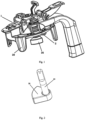
Fig. 1 is a structure diagram of the present invention. -
Fig. 2 is a structure diagram of a pressing rod and a presser foot. -
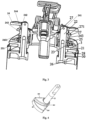
Fig. 3 is a sectional structure diagram of a lifting handle with a cam in the present invention. -
Fig. 4 is a structure diagram of a pressing rod and a stepped presser foot at an end thereof. -
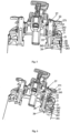
Fig. 5 is an isometric sectional structure diagram of a first presser foot surface pressing against a paint bucket opening. -
Fig. 6 is an isometric sectional structure diagram of a second presser foot surface pressing against a paint bucket opening. - As shown in
Figs. 1-6 , a labor-saving paint mixing cover adapted to different paint bucket openings includes a paint outlet mechanism 1 for controlling a paint to be poured out, and at least twopressing mechanisms 2 for pressing a paint bucket and the canister lid, wherein for each pressing mechanism, the canister lid is provided with athrough hole 21; apressing rod 22 penetrates through the through hole; aseal sleeve 23 is sleeved outside thepressing rod 22; aseal sleeve flange 231 of theseal sleeve 23 is pressed against thecanister lid 3; a compressedspring 25 is sleeved at the outer periphery of thepressing rod 22 between theseal sleeve flange 231 of theseal sleeve 23 and an upper end of thepressing rod 22; apresser foot 26 is provided at a lower end of thepressing rod 22, characterized in that a handle is provided at an upper end of the pressing rod and is acam lifting handle 241 formed by hinging the upper end of the pressing rod and a cam; acam surface 242 of thecam lifting handle 241 is in contact with an upper surface of a cam seat; the cam seat is amovable pipe sleeve 243 sleeved outside the pressing rod; anupper surface 244 of themovable pipe sleeve 243 is in contact with thecam surface 242 of the cam lifting handle; themovable pipe sleeve 243 is provided with a movablepipe sleeve flange 2431; and the upper end of the pressingspring 25 abuts against the movablepipe sleeve flange 2431 of themovable pipe sleeve 243. - In the prior art, when the lid is compressed, the knob also needs to be pressed and rotated to ensure the presser foot is clamped on the
paint bucket 301. Often, to ensure the sealing performance of the banister lid, the compressed spring of the knob is designed to have great elasticity. When the knob is rotated, the compressed spring needs to be pressed continuously. This can generate a very large counteracting force on the finger. The hand is squeezed and the operation is strenuous, and a person feels very uncomfortable in the case of repeated installation. As the cam lifting handle is adopted, when the spring is pressed, a long shaft of the cam lifting hand is in contact with the upper surface of the cam seat; at that time, the cam lifting handle is horizontally rotated, so that the presser foot presses against the paint bucket opening; in the entire horizontal rotation process, the hand only needs to hold the handle part to avoid return of the cam, so that the compressed spring is pressed continuously, and the working pressure of the finger is reduced, thereby saving physical work and facilitating operation. - A
bracket 27 is provided correspondingly above the throughhole 21 of thecanister lid 3; an upper flat plate of thebracket 27 is provided with a bracket throughhole 271; themovable pipe sleeve 243 is placed in the bracket throughhole 271; and themovable pipe sleeve 243 and the bracket throughhole 271 are in sliding fit to each other. As such, the whole pressing mechanism is supported by the upper through hole and the lower through hole, and is relatively firm. Areset spring 28 is sleeved at the outer periphery of the pressing rod between the lower side of the canister lid and the presser foot. With this design, the pressing mechanism can be prevented from moving when the presser foot is in a relaxed state. There are two or four pressing mechanisms. - When the canister lid is mounted on the
paint bucket 301, firstly it needs to manually adjust the canister lid to be concentric to the paint bucket with visual inspection, to ensure the canister lid is mounted in place without offset; otherwise, a leakage event may occur. At least threeclamping jaws 29 are provided at the periphery of the canister lid. When the stirring canister lid works, the plurality of clamping jaws surround the outer side of the paint bucket, and the canister lid can be adjusted to be concentric to the paint bucket. Four clamping jaws are added to the new structure of the canister lid. When the canister lid is sleeved on the paint bucket, center adjustment can be achieved to ensure the canister lid is centered, without manually adjusting the position of the canister lid to be centered, wherein four clamping jaws with the same size are uniformly distributed around the canister lid; and when canister lid is sleeved on the paint bucket, the four clamping jaws can be automatically pressed uniformly into a groove according to the outer diameter of the paint bucket, to ensure the canister lid is sleeved in a centered manner. - The separation of the knob rotating and knob pressing operations is achieved as follows:
The canister lid adopts a novel sealing structure suitable for a paint container and a canister lid, and comprises lid body in sealed connection with the container, and a knob, springs, a presser foot, a seal ring and the like for cooperative operation of an upper and a lower surface of the lid body. First, the lid body is provided with a special structure for installing the seal ring, the compressed spring and a locking support. With this structure, the three workpieces can be assembled and connected from bottom to top, and the compressed spring can bidirectionally tighten the seal ring at the lower end and the locking support at the upper end. Then, the presser foot and the reset spring are mounted at the lower end of the lid body. The two workpieces penetrate through the lid body and the afore-mentioned seal ring. The spring and other parts are connected to the knob at the upper end of the lid body. By rotating the knob, the presser foot is rotated, and contraction of the presser foot is controlled. After the presser foot rotates in place, a knob pressing platform is pressed down, and by using the cam lifting handle on the knob, the compressed spring and the locking support, the presser foot is lifted up, so that the seal ring and alower edge 30 of a boss of the paint bucket opening completely fit to each other to achieve a sealing effect. To change the paint bucket, first, the knob pressing platform is lifted up, the presser foot is pushed out by using the reset spring between the presser foot and the lid body, and then the cam lifting handle is rotated in a reversed direction to contract the presser foot, and the paint bucket can be changed. - The present invention achieves automatic centering in canister lid product installation, and achieves separation of pressing and rotating operations in the canister installation. The operation is easy and quick.
- The presser foot surface is sector-ring-shaped, and is provided with a
vertical surface 261 along a connecting line between two arc lines in the shape of section rings. Thevertical surface 261 divides the sector-ring surface into two presser foot surfaces with different heights and in a stepped manner, that is, afirst presser foot 262 and asecond presser foot 263. - With this design, using multiple pressing surfaces, the same presser foot can be used to press paint buckets with different paint bucket opening thicknesses, unlike the prior art in which one presser foot can only be used to press paint buckets with the same bucket opening thickness. This configuration adopts the presser foot with a two-segment structure, which can be adapted to paint buckets with different clamping heights, improve the universality. The presser foot with the new structure is specially designed with two working surfaces with different heights, and the upper and lower working surfaces are spaced from the fitting surface of the seal right by different heights. This leads to an advantage that it can be adapted to paint buckets with different clamping heights from different customers. When the clamping height of the paint bucket of the customer is less than 7mm, the upper plane can used to fit to and seal the paint bucket. When the clamping height of the paint bucket of the customer is more than 7mm and less than 12mm, the lower plane is used to fit to and seal the paint bucket. Designing the presser feet of the canister lid into presser feet with different heights and different specifications can achieve compatibility.
- In the prior art, when the lid is compressed, the knob also needs to be pressed and rotated to ensure the presser foot is clamped on the paint bucket. Often, to ensure the sealing performance of the banister lid, the compressed spring of the knob is designed to have great elasticity. When the knob is rotated, the compressed spring needs to be pressed continuously. This can generate a very large counteracting force on the finger. The hand is squeezed and the operation is strenuous, and a person feels very uncomfortable in the case of repeated installation. As the cam lifting handle is adopted, when the spring is pressed, a long shaft of the cam lifting hand is in contact with the upper surface of the cam seat; at that time, the cam lifting handle is horizontally rotated, so that the presser foot presses against the paint bucket opening.
Fig. 5 is an isometric sectional structure diagram of a first presser foot surface pressing against a paint bucket opening.Fig. 6 is an isometric sectional structure diagram of a second presser foot surface pressing against a paint bucket opening. In the entire horizontal rotation process, the hand only needs to hold the handle part to avoid return of the cam, so that the compressed spring is pressed continuously, and the working pressure of the finger is reduced, thereby saving physical work and facilitating operation. - There are three or four clamping
jaws 29. - The present application is specially directed to the newest universal canister lid of the company. The new structure can adapt to paint buckets of most brands in the market, does not need secondary processing or adjustment and is highly universal. Moreover, the canister lid is simple to operate and comfortable on the hand during operation, and eliminates the shortcoming that the hand is squeezed during pressing and rotating operations of the previous canister lids.
Claims (1)
- Labor-saving paint mixing cover, comprising a paint outlet mechanism (1) for controlling a paint to be poured out, and at least two pressing mechanisms (2) for pressing a paint bucket and the canister lid, wherein for each pressing mechanism, the canister lid is provided with a through hole (21); a pressing rod (22) penetrates through the through hole; a seal sleeve (23) is sleeved outside the pressing rod (22); a seal sleeve flange (231) of the seal sleeve (23) is pressed against the canister lid (3); a compressed spring (25) is sleeved at the outer periphery of the pressing rod (22) between the seal sleeve flange (231) of the seal sleeve (23) and an upper end of the pressing rod (22); a presser foot (26) is provided at a lower end of the pressing rod (22), a handle is provided at an upper end of the pressing rod and is a cam lifting handle (241) formed by hinging the upper end of the pressing rod and a cam; a cam surface (242) of the cam lifting handle (241) is in contact with an upper surface of a cam seat; the cam seat is a movable pipe sleeve (243) sleeved outside the pressing rod; an upper surface (244) of the movable pipe sleeve (243) is in contact with the cam surface (242) of the cam lifting handle; the movable pipe sleeve (243) is provided with a movable pipe sleeve flange (2431); the upper end of the pressing spring (25) abuts against the movable pipe sleeve flange (2431) of the movable pipe sleeve (243); wherein a bracket (27) is provided correspondingly above the through hole (21) of the canister lid (3); an upper flat plate of the bracket (27) is provided with a bracket through hole (271); the movable pipe sleeve (243) is placed in the bracket through hole (271); and the movable pipe sleeve (243) and the bracket through hole (271) are in sliding fit to each other, characterisied in that a reset spring (28) is sleeved at the outer periphery of the pressing rod (22) between a lower side of the canister lid (3) and the presser foot (26), so that the pressing mechanism (2) can be prevented from moving when the presser foot (26) is in a relaxed state.
Applications Claiming Priority (2)
| Application Number | Priority Date | Filing Date | Title |
|---|---|---|---|
| CN201610598470.1A CN107661725B (en) | 2016-07-27 | 2016-07-27 | Labor-saving stirring paddle cover |
| PCT/CN2017/094252 WO2018019221A1 (en) | 2016-07-27 | 2017-07-25 | Labor-saving paint mixing cover |
Publications (3)
| Publication Number | Publication Date |
|---|---|
| EP3492163A1 EP3492163A1 (en) | 2019-06-05 |
| EP3492163A4 EP3492163A4 (en) | 2020-03-11 |
| EP3492163B1 true EP3492163B1 (en) | 2025-04-30 |
Family
ID=61015660
Family Applications (1)
| Application Number | Title | Priority Date | Filing Date |
|---|---|---|---|
| EP17833524.6A Active EP3492163B1 (en) | 2016-07-27 | 2017-07-25 | Labor-saving paint mixing cover |
Country Status (4)
| Country | Link |
|---|---|
| US (1) | US10639604B2 (en) |
| EP (1) | EP3492163B1 (en) |
| CN (1) | CN107661725B (en) |
| WO (1) | WO2018019221A1 (en) |
Families Citing this family (1)
| Publication number | Priority date | Publication date | Assignee | Title |
|---|---|---|---|---|
| CN114030754B (en) * | 2021-11-18 | 2023-12-12 | 硕腾检测科技有限公司 | Reagent tube storage device for biological agent |
Family Cites Families (21)
| Publication number | Priority date | Publication date | Assignee | Title |
|---|---|---|---|---|
| US1486199A (en) * | 1919-05-19 | 1924-03-11 | Ira T Skiles | Combination perforator, closure, and pouring attachment for containers |
| US1805257A (en) * | 1927-09-08 | 1931-05-12 | Frederick D Pitt | Dispensing bottle stopper |
| US1731764A (en) * | 1927-11-03 | 1929-10-15 | Joseph G Coffin | Dispensing device |
| US2585334A (en) * | 1949-01-19 | 1952-02-12 | Rinshed Mason Company | Closure for paint cans |
| US3162338A (en) * | 1962-07-25 | 1964-12-22 | Nicholas T Grubelic | Closure device for liquid containers such as paint cans |
| FR2675775B1 (en) * | 1991-04-26 | 1995-01-06 | Fillon Pichon Sa | LID DEVICE WITH AGITATOR FOR PAINT CAN. |
| US5533802A (en) * | 1995-03-06 | 1996-07-09 | Garganese; Richard S. | Paint can accessory |
| IT1283273B1 (en) | 1996-03-18 | 1998-04-16 | Tecmec S R L | MIXER LID STRUCTURE, ESPECIALLY DESIGNED FOR PAINT JARS AND THE LIKE. |
| CN2458244Y (en) | 2001-01-05 | 2001-11-07 | 张利锋 | Pail cover charging open resetting mechanism with stirrer |
| US6511218B2 (en) * | 2001-04-05 | 2003-01-28 | Dedoes Industries, Inc. | Cover assembly for a paint can |
| CN2490086Y (en) | 2001-06-15 | 2002-05-08 | 郑州三华科技实业有限公司 | Location anti-rotation device on cover of colour paint mixing barrel |
| CN2595461Y (en) * | 2002-12-18 | 2003-12-31 | 郑州三华科技实业有限公司 | Color paint bucket cover with anti-slip pressrod fixing base |
| CN2595706Y (en) | 2002-12-27 | 2003-12-31 | 郑州三华科技实业有限公司 | Bore adjustable color paint bucket lid |
| US7540652B2 (en) * | 2003-08-28 | 2009-06-02 | Dedoes Industries, Inc. | Paint can cover assembly with improved locking means |
| US8424704B2 (en) * | 2004-06-02 | 2013-04-23 | X-Pert Paint Mixing Systems, Inc. | Self-cleaning lid for a paint container fluid pour spout |
| US7431183B2 (en) * | 2004-08-03 | 2008-10-07 | Dedoes Industries, Inc. | Cover assembly for a paint can having an improved seal |
| JP4893315B2 (en) | 2007-01-09 | 2012-03-07 | タイガー魔法瓶株式会社 | Beverage container stopper structure |
| CN203020695U (en) * | 2012-12-07 | 2013-06-26 | 沈如华 | Grout cover used for paint bucket |
| EP2931412A2 (en) * | 2012-12-13 | 2015-10-21 | 3M Innovative Properties Company | Cover assembly for dispensing liquids from containers |
| CN203998869U (en) | 2014-08-18 | 2014-12-10 | 浙江曼得丽涂料有限公司 | A kind of paint can cover locking device |
| CN107661704B (en) * | 2016-07-27 | 2020-06-09 | 郑州三华科技实业有限公司 | Stirring paddle cover suitable for mouths of different paint buckets |
-
2016
- 2016-07-27 CN CN201610598470.1A patent/CN107661725B/en active Active
-
2017
- 2017-07-25 US US16/320,866 patent/US10639604B2/en active Active
- 2017-07-25 WO PCT/CN2017/094252 patent/WO2018019221A1/en not_active Ceased
- 2017-07-25 EP EP17833524.6A patent/EP3492163B1/en active Active
Also Published As
| Publication number | Publication date |
|---|---|
| US10639604B2 (en) | 2020-05-05 |
| WO2018019221A1 (en) | 2018-02-01 |
| EP3492163A1 (en) | 2019-06-05 |
| US20190168179A1 (en) | 2019-06-06 |
| CN107661725B (en) | 2020-06-09 |
| EP3492163A4 (en) | 2020-03-11 |
| CN107661725A (en) | 2018-02-06 |
Similar Documents
| Publication | Publication Date | Title |
|---|---|---|
| US6435426B1 (en) | Floating gasket plate for paint cup on spray gun | |
| EP3153460B1 (en) | Container with pressure relief valve | |
| US2263842A (en) | Means for connecting containers to spraying devices | |
| US5203465A (en) | Lid with a valve-containing knob for a cooking utensil | |
| EP3492181B1 (en) | Agitator lid suitable for different paint pot openings | |
| JP2598888B2 (en) | Opening device for Otaru spout | |
| US10639604B2 (en) | Labor-saving paint mixing cover | |
| JPH0144594B2 (en) | ||
| US3190306A (en) | Single lever faucet | |
| CN219602046U (en) | Lid and container | |
| US2577417A (en) | Pump combination | |
| US3182866A (en) | Spray gun transition piece | |
| CN219720531U (en) | Adjustable quantitative oilcan | |
| US4557669A (en) | Pumping apparatus | |
| CN116331656A (en) | Lids and Serving Containers | |
| KR20040079832A (en) | Closing device for a container | |
| EP0552136A1 (en) | Improved butterfly valve | |
| CN111166162A (en) | Pressure cooker with opening and closing and gear-shifting control mechanism | |
| CN213248513U (en) | Sealed anti-scalding type strengthened glass pot cover | |
| AU2011207112B2 (en) | A tap valve assembly | |
| CN209090826U (en) | Clamp forceps type pressure cooker | |
| CN112006532B (en) | Pot cover assembly and cooking utensils | |
| KR200336736Y1 (en) | Apparatus for opening and closing the lid of a pressure cooker | |
| CN220308846U (en) | Cup cover assembly and cup | |
| CN217592604U (en) | Pot lid and have heat preservation kettle of pot lid |
Legal Events
| Date | Code | Title | Description |
|---|---|---|---|
| STAA | Information on the status of an ep patent application or granted ep patent |
Free format text: STATUS: THE INTERNATIONAL PUBLICATION HAS BEEN MADE |
|
| PUAI | Public reference made under article 153(3) epc to a published international application that has entered the european phase |
Free format text: ORIGINAL CODE: 0009012 |
|
| STAA | Information on the status of an ep patent application or granted ep patent |
Free format text: STATUS: REQUEST FOR EXAMINATION WAS MADE |
|
| 17P | Request for examination filed |
Effective date: 20190225 |
|
| AK | Designated contracting states |
Kind code of ref document: A1 Designated state(s): AL AT BE BG CH CY CZ DE DK EE ES FI FR GB GR HR HU IE IS IT LI LT LU LV MC MK MT NL NO PL PT RO RS SE SI SK SM TR |
|
| AX | Request for extension of the european patent |
Extension state: BA ME |
|
| DAV | Request for validation of the european patent (deleted) | ||
| DAX | Request for extension of the european patent (deleted) | ||
| A4 | Supplementary search report drawn up and despatched |
Effective date: 20200212 |
|
| RIC1 | Information provided on ipc code assigned before grant |
Ipc: B01F 7/00 20060101AFI20200206BHEP Ipc: B65D 51/14 20060101ALI20200206BHEP Ipc: B44D 3/12 20060101ALI20200206BHEP |
|
| STAA | Information on the status of an ep patent application or granted ep patent |
Free format text: STATUS: EXAMINATION IS IN PROGRESS |
|
| 17Q | First examination report despatched |
Effective date: 20211208 |
|
| REG | Reference to a national code |
Free format text: PREVIOUS MAIN CLASS: B01F0007000000 Ipc: B44D0003120000 Ref country code: DE Ref legal event code: R079 Ref document number: 602017089230 Country of ref document: DE Free format text: PREVIOUS MAIN CLASS: B01F0007000000 Ipc: B44D0003120000 |
|
| GRAP | Despatch of communication of intention to grant a patent |
Free format text: ORIGINAL CODE: EPIDOSNIGR1 |
|
| STAA | Information on the status of an ep patent application or granted ep patent |
Free format text: STATUS: GRANT OF PATENT IS INTENDED |
|
| RIC1 | Information provided on ipc code assigned before grant |
Ipc: B65D 51/14 20060101ALI20241220BHEP Ipc: B44D 3/12 20060101AFI20241220BHEP |
|
| INTG | Intention to grant announced |
Effective date: 20250109 |
|
| GRAS | Grant fee paid |
Free format text: ORIGINAL CODE: EPIDOSNIGR3 |
|
| GRAA | (expected) grant |
Free format text: ORIGINAL CODE: 0009210 |
|
| STAA | Information on the status of an ep patent application or granted ep patent |
Free format text: STATUS: THE PATENT HAS BEEN GRANTED |
|
| AK | Designated contracting states |
Kind code of ref document: B1 Designated state(s): AL AT BE BG CH CY CZ DE DK EE ES FI FR GB GR HR HU IE IS IT LI LT LU LV MC MK MT NL NO PL PT RO RS SE SI SK SM TR |
|
| REG | Reference to a national code |
Ref country code: CH Ref legal event code: EP Ref country code: GB Ref legal event code: FG4D |
|
| REG | Reference to a national code |
Ref country code: IE Ref legal event code: FG4D |
|
| REG | Reference to a national code |
Ref country code: DE Ref legal event code: R096 Ref document number: 602017089230 Country of ref document: DE |
|
| PGFP | Annual fee paid to national office [announced via postgrant information from national office to epo] |
Ref country code: FR Payment date: 20250626 Year of fee payment: 9 |
|
| REG | Reference to a national code |
Ref country code: NL Ref legal event code: MP Effective date: 20250430 |
|
| REG | Reference to a national code |
Ref country code: AT Ref legal event code: MK05 Ref document number: 1789707 Country of ref document: AT Kind code of ref document: T Effective date: 20250430 |
|
| PG25 | Lapsed in a contracting state [announced via postgrant information from national office to epo] |
Ref country code: PT Free format text: LAPSE BECAUSE OF FAILURE TO SUBMIT A TRANSLATION OF THE DESCRIPTION OR TO PAY THE FEE WITHIN THE PRESCRIBED TIME-LIMIT Effective date: 20250901 Ref country code: FI Free format text: LAPSE BECAUSE OF FAILURE TO SUBMIT A TRANSLATION OF THE DESCRIPTION OR TO PAY THE FEE WITHIN THE PRESCRIBED TIME-LIMIT Effective date: 20250430 Ref country code: ES Free format text: LAPSE BECAUSE OF FAILURE TO SUBMIT A TRANSLATION OF THE DESCRIPTION OR TO PAY THE FEE WITHIN THE PRESCRIBED TIME-LIMIT Effective date: 20250430 |
|
| PGFP | Annual fee paid to national office [announced via postgrant information from national office to epo] |
Ref country code: DE Payment date: 20250722 Year of fee payment: 9 |
|
| REG | Reference to a national code |
Ref country code: LT Ref legal event code: MG9D |
|
| PG25 | Lapsed in a contracting state [announced via postgrant information from national office to epo] |
Ref country code: GR Free format text: LAPSE BECAUSE OF FAILURE TO SUBMIT A TRANSLATION OF THE DESCRIPTION OR TO PAY THE FEE WITHIN THE PRESCRIBED TIME-LIMIT Effective date: 20250731 Ref country code: NO Free format text: LAPSE BECAUSE OF FAILURE TO SUBMIT A TRANSLATION OF THE DESCRIPTION OR TO PAY THE FEE WITHIN THE PRESCRIBED TIME-LIMIT Effective date: 20250730 |
|
| PG25 | Lapsed in a contracting state [announced via postgrant information from national office to epo] |
Ref country code: NL Free format text: LAPSE BECAUSE OF FAILURE TO SUBMIT A TRANSLATION OF THE DESCRIPTION OR TO PAY THE FEE WITHIN THE PRESCRIBED TIME-LIMIT Effective date: 20250430 Ref country code: PL Free format text: LAPSE BECAUSE OF FAILURE TO SUBMIT A TRANSLATION OF THE DESCRIPTION OR TO PAY THE FEE WITHIN THE PRESCRIBED TIME-LIMIT Effective date: 20250430 |
|
| PGFP | Annual fee paid to national office [announced via postgrant information from national office to epo] |
Ref country code: IT Payment date: 20250808 Year of fee payment: 9 |
|
| PG25 | Lapsed in a contracting state [announced via postgrant information from national office to epo] |
Ref country code: BG Free format text: LAPSE BECAUSE OF FAILURE TO SUBMIT A TRANSLATION OF THE DESCRIPTION OR TO PAY THE FEE WITHIN THE PRESCRIBED TIME-LIMIT Effective date: 20250430 |
|
| PG25 | Lapsed in a contracting state [announced via postgrant information from national office to epo] |
Ref country code: HR Free format text: LAPSE BECAUSE OF FAILURE TO SUBMIT A TRANSLATION OF THE DESCRIPTION OR TO PAY THE FEE WITHIN THE PRESCRIBED TIME-LIMIT Effective date: 20250430 |
|
| PG25 | Lapsed in a contracting state [announced via postgrant information from national office to epo] |
Ref country code: AT Free format text: LAPSE BECAUSE OF FAILURE TO SUBMIT A TRANSLATION OF THE DESCRIPTION OR TO PAY THE FEE WITHIN THE PRESCRIBED TIME-LIMIT Effective date: 20250430 |
|
| PG25 | Lapsed in a contracting state [announced via postgrant information from national office to epo] |
Ref country code: RS Free format text: LAPSE BECAUSE OF FAILURE TO SUBMIT A TRANSLATION OF THE DESCRIPTION OR TO PAY THE FEE WITHIN THE PRESCRIBED TIME-LIMIT Effective date: 20250731 |
|
| PG25 | Lapsed in a contracting state [announced via postgrant information from national office to epo] |
Ref country code: IS Free format text: LAPSE BECAUSE OF FAILURE TO SUBMIT A TRANSLATION OF THE DESCRIPTION OR TO PAY THE FEE WITHIN THE PRESCRIBED TIME-LIMIT Effective date: 20250830 |
|
| PG25 | Lapsed in a contracting state [announced via postgrant information from national office to epo] |
Ref country code: LV Free format text: LAPSE BECAUSE OF FAILURE TO SUBMIT A TRANSLATION OF THE DESCRIPTION OR TO PAY THE FEE WITHIN THE PRESCRIBED TIME-LIMIT Effective date: 20250430 |
|
| PG25 | Lapsed in a contracting state [announced via postgrant information from national office to epo] |
Ref country code: SM Free format text: LAPSE BECAUSE OF FAILURE TO SUBMIT A TRANSLATION OF THE DESCRIPTION OR TO PAY THE FEE WITHIN THE PRESCRIBED TIME-LIMIT Effective date: 20250430 Ref country code: DK Free format text: LAPSE BECAUSE OF FAILURE TO SUBMIT A TRANSLATION OF THE DESCRIPTION OR TO PAY THE FEE WITHIN THE PRESCRIBED TIME-LIMIT Effective date: 20250430 |
|
| PG25 | Lapsed in a contracting state [announced via postgrant information from national office to epo] |
Ref country code: CZ Free format text: LAPSE BECAUSE OF FAILURE TO SUBMIT A TRANSLATION OF THE DESCRIPTION OR TO PAY THE FEE WITHIN THE PRESCRIBED TIME-LIMIT Effective date: 20250430 |
|
| PG25 | Lapsed in a contracting state [announced via postgrant information from national office to epo] |
Ref country code: EE Free format text: LAPSE BECAUSE OF FAILURE TO SUBMIT A TRANSLATION OF THE DESCRIPTION OR TO PAY THE FEE WITHIN THE PRESCRIBED TIME-LIMIT Effective date: 20250430 |
|
| PG25 | Lapsed in a contracting state [announced via postgrant information from national office to epo] |
Ref country code: SK Free format text: LAPSE BECAUSE OF FAILURE TO SUBMIT A TRANSLATION OF THE DESCRIPTION OR TO PAY THE FEE WITHIN THE PRESCRIBED TIME-LIMIT Effective date: 20250430 Ref country code: RO Free format text: LAPSE BECAUSE OF FAILURE TO SUBMIT A TRANSLATION OF THE DESCRIPTION OR TO PAY THE FEE WITHIN THE PRESCRIBED TIME-LIMIT Effective date: 20250430 |
|
| REG | Reference to a national code |
Ref country code: DE Ref legal event code: R097 Ref document number: 602017089230 Country of ref document: DE |
|
| REG | Reference to a national code |
Ref country code: CH Ref legal event code: H13 Free format text: ST27 STATUS EVENT CODE: U-0-0-H10-H13 (AS PROVIDED BY THE NATIONAL OFFICE) Effective date: 20260224 |
|
| PLBE | No opposition filed within time limit |
Free format text: ORIGINAL CODE: 0009261 |
|
| STAA | Information on the status of an ep patent application or granted ep patent |
Free format text: STATUS: NO OPPOSITION FILED WITHIN TIME LIMIT |
|
| REG | Reference to a national code |
Ref country code: CH Ref legal event code: L10 Free format text: ST27 STATUS EVENT CODE: U-0-0-L10-L00 (AS PROVIDED BY THE NATIONAL OFFICE) Effective date: 20260311 |
|
| PG25 | Lapsed in a contracting state [announced via postgrant information from national office to epo] |
Ref country code: LU Free format text: LAPSE BECAUSE OF NON-PAYMENT OF DUE FEES Effective date: 20250725 |
|
| GBPC | Gb: european patent ceased through non-payment of renewal fee |
Effective date: 20250730 |
|
| REG | Reference to a national code |
Ref country code: BE Ref legal event code: MM Effective date: 20250731 |
|
| 26N | No opposition filed |
Effective date: 20260202 |
|
| PG25 | Lapsed in a contracting state [announced via postgrant information from national office to epo] |
Ref country code: GB Free format text: LAPSE BECAUSE OF NON-PAYMENT OF DUE FEES Effective date: 20250730 |
|
| PG25 | Lapsed in a contracting state [announced via postgrant information from national office to epo] |
Ref country code: BE Free format text: LAPSE BECAUSE OF NON-PAYMENT OF DUE FEES Effective date: 20250731 |
|
| PG25 | Lapsed in a contracting state [announced via postgrant information from national office to epo] |
Ref country code: CH Free format text: LAPSE BECAUSE OF NON-PAYMENT OF DUE FEES Effective date: 20250731 |