EP3491997A1 - System and method for creating a customized anatomical model of an eye - Google Patents
System and method for creating a customized anatomical model of an eye Download PDFInfo
- Publication number
- EP3491997A1 EP3491997A1 EP18214436.0A EP18214436A EP3491997A1 EP 3491997 A1 EP3491997 A1 EP 3491997A1 EP 18214436 A EP18214436 A EP 18214436A EP 3491997 A1 EP3491997 A1 EP 3491997A1
- Authority
- EP
- European Patent Office
- Prior art keywords
- axis
- reference point
- eye
- image
- point
- Prior art date
- Legal status (The legal status is an assumption and is not a legal conclusion. Google has not performed a legal analysis and makes no representation as to the accuracy of the status listed.)
- Granted
Links
Images

Classifications
-
- A—HUMAN NECESSITIES
- A61—MEDICAL OR VETERINARY SCIENCE; HYGIENE
- A61B—DIAGNOSIS; SURGERY; IDENTIFICATION
- A61B34/00—Computer-aided surgery; Manipulators or robots specially adapted for use in surgery
- A61B34/10—Computer-aided planning, simulation or modelling of surgical operations
-
- A—HUMAN NECESSITIES
- A61—MEDICAL OR VETERINARY SCIENCE; HYGIENE
- A61B—DIAGNOSIS; SURGERY; IDENTIFICATION
- A61B3/00—Apparatus for testing the eyes; Instruments for examining the eyes
- A61B3/0016—Operational features thereof
- A61B3/0025—Operational features thereof characterised by electronic signal processing, e.g. eye models
-
- A—HUMAN NECESSITIES
- A61—MEDICAL OR VETERINARY SCIENCE; HYGIENE
- A61B—DIAGNOSIS; SURGERY; IDENTIFICATION
- A61B3/00—Apparatus for testing the eyes; Instruments for examining the eyes
- A61B3/10—Objective types, i.e. instruments for examining the eyes independent of the patients' perceptions or reactions
- A61B3/117—Objective types, i.e. instruments for examining the eyes independent of the patients' perceptions or reactions for examining the anterior chamber or the anterior chamber angle, e.g. gonioscopes
Definitions
- the present invention pertains generally to systems and methods for creating templates. More particularly, the present invention pertains to systems and methods for creating templates that are useful as a control reference for moving a laser beam's focal point during ophthalmic surgery. The present invention is particularly, but not exclusively, useful as a system and method for creating templates that will replicate the anatomical object that is to be altered during a laser ophthalmic surgery.
- any ophthalmic surgical procedure must be accomplished with great accuracy and precision. This is particularly so when a laser system will be used to cut or ablate tissue deep inside an eye. In such cases, it becomes particularly important that there is some operational base reference which can be established to control movements of the laser beam's focal point during a surgery.
- Imaging devices such as those that employ Optical Coherence Tomography (OCT) techniques, have been particularly helpful for providing information that is useful in performing ophthalmic laser surgeries. Nevertheless, OCT imaging techniques, alone, are not always able to provide the degree of precision that is required to establish a discernible and accurate base reference for the control of laser surgeries within the eye. For any number of reasons, an OCT image may lack the sharpness or clarity that is necessary or desired. In the specific case of ophthalmic surgeries, however, the eye itself can be helpful in overcoming these deficiencies.
- OCT Optical Coherence Tomography
- the anatomy of an eye is well known.
- the eye's anatomy is unique because, unlike most other body parts, many of its structures are substantially symmetrical.
- the light refractive, optical elements of the eye are all aligned along a definable central axis, and they are arranged in a known anatomical order. It happens that the central axis can be easily identified for such an arrangement of optical elements, and it can be accurately defined by any of several standard techniques.
- the interface surfaces between different optical structures inside the eye can be effectively imaged by OCT. Consequently, the location of an intersection between an interface surface and the central axis can also be accurately established by OCT. Moreover, due to their symmetry on the central axis, the size and extent of the various optical elements in the eye can also be predicted with great accuracy. As recognized by the present invention, such a replication of structural elements can be used, altogether or in part, to establish a base reference for use in an ophthalmic laser procedure.
- an object of the present invention to provide a system and method that will establish a base reference inside an eye for controlling an ophthalmic laser procedure.
- Another object of the present invention is to provide a system and method for using OCT techniques to establish a base reference that results from an automated anatomical recognition of different optical elements in an eye (i.e. different refractive tissues) and the location of these elements (tissues).
- Still another object of the present invention is to provide a system and method for establishing a base reference inside an eye that is easy to assemble, is simple to use and is comparatively cost effective.
- a system and method are provided for replicating anatomical features inside an eye. Specifically, this is done to create a template for identifying anatomical structures that can be used as a base reference for controlling a laser system during ophthalmic laser surgery (e.g. a capsulotomy) inside the eye.
- a laser system during ophthalmic laser surgery e.g. a capsulotomy
- a first step in the creation of a template involves the identification of a central ("z") axis for the eye. Structurally, this "z" axis needs to be identified such that the optical elements (i.e. light refractive structures) of the eye will be symmetrically aligned along the axis.
- an OCT device is used to create a cross sectional image of the eye. Importantly, this image is created to include the "z” axis. Once the OCT cross sectional image has been created, and the central "z” axis has been incorporated into the image, various reference points are established along the central "z" axis.
- each of the reference points is selected and located where an interface surface between adjacent optical elements in the eye intersects the central "z" axis.
- each reference point is specifically related to a particularly identified anatomical surface in the image.
- the result is a plurality of contiguous lengths ( ⁇ "z" n ) along the "z" axis that are individually measured between adjacent reference points. These lengths will be anatomically recognized and can be measured with great accuracy.
- a template based on the "z" axis has been created that can be used to replicate the optical elements of the eye.
- a refinement for the present invention can be made by accounting for any tilt there might be between the central "z" axis and the optical elements of the eye. As noted above, the optical elements need to be symmetrically aligned along the central "z" axis. In accordance with the present invention, compensation for a tilt angle " ⁇ " can be accomplished in either of two ways.
- a first axis is identified that is substantially parallel to the base reference axis, and is at a distance "d 1 " from the base reference axis.
- a first reference point is then located on the first axis where the first axis intersects the interface surface.
- the z-location of the first reference point is then compared with an expected z-location for the first reference point to determine a first differential ( ⁇ z ').
- a second axis is identified that is also substantially parallel to the base reference axis, at a distance "d 2 " from the base reference axis.
- a second reference point is then located on the second axis where the second axis intersects the interface surface.
- the z-location of the second reference point is then compared with an expected location for the second reference point to determine a second differential ( ⁇ z ').
- ⁇ z ' and ⁇ z " along with a measurement of the angle between the respective planes identified by the first and second axes with the base reference axis (e.g. 90° for XZ and YZ planes), are used to measure an angle of tilt ( ⁇ ) for the interface surface.
- the tilt angle ⁇ can then be used to refine the establishment of the central "z" axis.
- a circular path in traced on the interface surface at a distance "r" from the base reference axis can then be measured to identify a differential ( ⁇ z ) relative to a rotation angle ( ⁇ ) about the base reference axis.
- ⁇ z is measured between a z max at ⁇ 1 and a z min at ⁇ 2 .
- the angle of tilt ( ⁇ ) for the interface surface can be measured.
- the tilt angle ⁇ can then be used to refine the orientation of the central "z" axis.
- a template with greater precision and accuracy can be created by verifying the location of previously selected reference points. To do this, at least one verification point is detected on the "z" axis in the OCT image. Like the original reference points, this verification point will be exactly located on the "z" axis at the intersection of an interface surface with the "z" axis. The location of the verification point in relation to the location of a previously selected reference point is then identified, and measurements are taken to confirm the anatomical identity of the surface that is associated with the reference point.
- a replica of the anatomical surface of an optical element can be symmetrically traced between adjacent reference points on the "z" axis.
- the replica is based on the location of the selected reference point(s) and on information in the image.
- at least one selected reference point, together with the "z" axis can then be used as a base reference for controlling a movement of a laser beam focal point relative to an identified surface.
- a first reference point can be located on a posterior surface of an anterior capsule
- a second reference point can be located on the anterior surface of a posterior capsule.
- the focal point of the laser beam can then be moved between the anterior capsule and the posterior capsule to perform a capsulotomy.
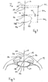
- a line recognition template in accordance with the present invention is shown and is generally designated 10.
- the template 10 essentially includes a central "z" axis 12 that is unique for the present invention in several important respects.
- the axis 12 is selected primarily for the symmetry it establishes for optical elements of the eye 14, such as the cornea 16, the crystalline lens 18 and the capsular bag 20 of the lens 18.
- optical elements of the eye 14 such as the cornea 16, the crystalline lens 18 and the capsular bag 20 of the lens 18.
- Fig. 2 it can be appreciated that each of these optical elements in the eye 14 will be axially symmetric relative to a properly oriented central "z" axis 12.
- each of these optical elements is anatomically recognizable and they are all arranged in a set anatomical order along the axis 12.
- the proper orientation of the axis 12 is initially established in relation to a cross sectional image of at least the anterior portion of the eye 14. As shown in Fig. 2 , this image is preferably made using an imaging device of a type well known in the pertinent art that is capable of OCT imaging. Once the central "z" axis 12 has been properly oriented on the OCT image (see Fig. 2 ), dimensional references that correspond to optical features of the eye 14 are established along the axis 12.
- the anterior surface 24 of cornea 16 can be imaged using OCT techniques.
- the surface 24 can be identified as the interface surface between the environmental air and the cornea 16. Consequently, the intersection of this surface 24 with the axis 12 can be used to accurately set a location for the reference point 22 on the axis 12.
- reference point 26 can be identified and located on the central "z" axis 12 at the intersection of the interface surface 28 with the axis 12.
- surface 28 is the interface between the cornea 16 and the anterior chamber 30 of eye 14 (see Fig. 2 ).
- the reference point 32 can be identified and located on the axis 12 at the intersection of an anterior interface surface 34 with the axis 12.
- the anterior interface surface 34 lies between the crystalline lens 18 and the capsular bag 20, in the anterior portion of the lens 18.
- the reference point 36 can be identified and located on the axis 12 at the intersection of posterior interface surface 38 with the axis 12.
- the posterior interface surface 38 in the posterior portion of the lens 18, lies between the crystalline lens 18 and the capsular bag 20.
- the template 10 is established with anatomically accurate dimensional information.
- the length " ⁇ z 1 " effectively represents the thickness of cornea 16 along the axis 12 between reference point 22 and reference point 26.
- the measured length of " ⁇ z 1 " is then anatomically determined with reference to the OCT image of eye 14 shown in Fig. 2 .
- the length " ⁇ z 2 " i.e. the length along axis 12 across the anterior chamber 30 between reference point 26 and reference point 32
- the result is a template 10 that can be superposed on an OCT image (see Fig. 3 ) and used as a control reference for ophthalmic surgical procedures, such as a capsulotomy.
- a template 10 which is created in accordance with the above disclosure can be verified for accuracy, if desired.
- a verification point 40 is selected.
- the verification point 40 shown in Fig. 1 is only exemplary, and it is taken to be the most anterior intersection of the capsular bag 20 with the central "z" axis 12.
- the corresponding verification distance " ⁇ v 1 i.e. the thickness of the capsular bag 20
- ⁇ v 1 can then be measured to determine whether the distance " ⁇ v 1 " and its location on the axis 12 will verify the accuracy of template 10.
- selected reference points can be used to trace the outline of optical elements in the eye 14.
- a traced outline of the crystalline lens 18 is shown by the dotted line 42.
- the dotted line 42 represents extensions of the interface surfaces 34 and 38, between the reference points 32 and 36 that replicate the boundary of the crystalline lens 18.
- this is only exemplary as it will be appreciated that similar extensions between other reference points can be made to replicate other optical elements in the eye 14.
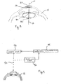
- the template 10 is superposed onto an OCT image of the eye 14 as shown in Fig. 3 . As mentioned above, this is done to establish a base reference that can be used by the computer/controller 44 for laser control purposes. As envisioned for the present invention, the template 10 (i.e. Fig. 3 ) is based on images of the eye 14 obtained from the imaging unit 46. As indicated in Fig. 4 , the computer/controller 44 can the effectively control the laser unit 48 to guide and control a laser beam 50 during an ophthalmic surgical operation in the eye 14.
Landscapes
- Health & Medical Sciences (AREA)
- Life Sciences & Earth Sciences (AREA)
- Engineering & Computer Science (AREA)
- Surgery (AREA)
- Veterinary Medicine (AREA)
- General Health & Medical Sciences (AREA)
- Public Health (AREA)
- Biomedical Technology (AREA)
- Heart & Thoracic Surgery (AREA)
- Medical Informatics (AREA)
- Molecular Biology (AREA)
- Animal Behavior & Ethology (AREA)
- Physics & Mathematics (AREA)
- Biophysics (AREA)
- Ophthalmology & Optometry (AREA)
- Signal Processing (AREA)
- Nuclear Medicine, Radiotherapy & Molecular Imaging (AREA)
- Robotics (AREA)
- Image Processing (AREA)
- Eye Examination Apparatus (AREA)
- Prostheses (AREA)
- Apparatus For Radiation Diagnosis (AREA)
Abstract
Description
- This application claims the benefit of
U.S. Provisional Patent Application Serial No. 61/636,582 61/636,582 - The present invention pertains generally to systems and methods for creating templates. More particularly, the present invention pertains to systems and methods for creating templates that are useful as a control reference for moving a laser beam's focal point during ophthalmic surgery. The present invention is particularly, but not exclusively, useful as a system and method for creating templates that will replicate the anatomical object that is to be altered during a laser ophthalmic surgery.
- It is axiomatic that any ophthalmic surgical procedure must be accomplished with great accuracy and precision. This is particularly so when a laser system will be used to cut or ablate tissue deep inside an eye. In such cases, it becomes particularly important that there is some operational base reference which can be established to control movements of the laser beam's focal point during a surgery.
- Imaging devices, such as those that employ Optical Coherence Tomography (OCT) techniques, have been particularly helpful for providing information that is useful in performing ophthalmic laser surgeries. Nevertheless, OCT imaging techniques, alone, are not always able to provide the degree of precision that is required to establish a discernible and accurate base reference for the control of laser surgeries within the eye. For any number of reasons, an OCT image may lack the sharpness or clarity that is necessary or desired. In the specific case of ophthalmic surgeries, however, the eye itself can be helpful in overcoming these deficiencies.
- The anatomy of an eye is well known. In particular, for the purpose of establishing a base reference, the eye's anatomy is unique because, unlike most other body parts, many of its structures are substantially symmetrical. Most importantly, the light refractive, optical elements of the eye are all aligned along a definable central axis, and they are arranged in a known anatomical order. It happens that the central axis can be easily identified for such an arrangement of optical elements, and it can be accurately defined by any of several standard techniques.
- It is well known that the interface surfaces between different optical structures inside the eye (e.g. the interface surface between the anterior chamber and the anterior capsule of the crystalline lens) can be effectively imaged by OCT. Consequently, the location of an intersection between an interface surface and the central axis can also be accurately established by OCT. Moreover, due to their symmetry on the central axis, the size and extent of the various optical elements in the eye can also be predicted with great accuracy. As recognized by the present invention, such a replication of structural elements can be used, altogether or in part, to establish a base reference for use in an ophthalmic laser procedure.
- In light of the above, it is an object of the present invention to provide a system and method that will establish a base reference inside an eye for controlling an ophthalmic laser procedure. Another object of the present invention is to provide a system and method for using OCT techniques to establish a base reference that results from an automated anatomical recognition of different optical elements in an eye (i.e. different refractive tissues) and the location of these elements (tissues). Still another object of the present invention is to provide a system and method for establishing a base reference inside an eye that is easy to assemble, is simple to use and is comparatively cost effective.
- In accordance with the present invention, a system and method are provided for replicating anatomical features inside an eye. Specifically, this is done to create a template for identifying anatomical structures that can be used as a base reference for controlling a laser system during ophthalmic laser surgery (e.g. a capsulotomy) inside the eye.
- As required for the present invention, a first step in the creation of a template involves the identification of a central ("z") axis for the eye. Structurally, this "z" axis needs to be identified such that the optical elements (i.e. light refractive structures) of the eye will be symmetrically aligned along the axis. Next, an OCT device is used to create a cross sectional image of the eye. Importantly, this image is created to include the "z" axis. Once the OCT cross sectional image has been created, and the central "z" axis has been incorporated into the image, various reference points are established along the central "z" axis. Specifically, based on the OCT image, each of the reference points is selected and located where an interface surface between adjacent optical elements in the eye intersects the central "z" axis. In this context, each reference point is specifically related to a particularly identified anatomical surface in the image. The result here is a plurality of contiguous lengths (Δ"z"n) along the "z" axis that are individually measured between adjacent reference points. These lengths will be anatomically recognized and can be measured with great accuracy. In essence, at this point a template based on the "z" axis has been created that can be used to replicate the optical elements of the eye.
- A refinement for the present invention can be made by accounting for any tilt there might be between the central "z" axis and the optical elements of the eye. As noted above, the optical elements need to be symmetrically aligned along the central "z" axis. In accordance with the present invention, compensation for a tilt angle "φ" can be accomplished in either of two ways.
- In order to compensate for a tilt angle "φ" (in both ways of compensating for "φ") it is first necessary to establish a base reference axis that is substantially oriented in a "z" direction. A base reference point is then located on the base reference axis. Importantly, the base reference point is located on an interface surface inside the eye (object).
- For one methodology of the present invention, a first axis is identified that is substantially parallel to the base reference axis, and is at a distance "d1" from the base reference axis. A first reference point is then located on the first axis where the first axis intersects the interface surface. The z-location of the first reference point is then compared with an expected z-location for the first reference point to determine a first differential (δz'). Similarly, a second axis is identified that is also substantially parallel to the base reference axis, at a distance "d2" from the base reference axis. A second reference point is then located on the second axis where the second axis intersects the interface surface. The z-location of the second reference point is then compared with an expected location for the second reference point to determine a second differential (δz'). With this first methodology δz' and δz", along with a measurement of the angle between the respective planes identified by the first and second axes with the base reference axis (e.g. 90° for XZ and YZ planes), are used to measure an angle of tilt (φ) for the interface surface. The tilt angle φ can then be used to refine the establishment of the central "z" axis.
- In another methodology, after a base reference axis is established and a base reference point is located on an interface surface inside the eye (object), a circular path in traced on the interface surface at a distance "r" from the base reference axis. Variations in "z" along the path can then be measured to identify a differential (δz) relative to a rotation angle (θ) about the base reference axis. Specifically, in this case, δz is measured between a zmax at θ1 and a zmin at θ2. Then, using δz, θ1 and θ2, the angle of tilt (φ) for the interface surface can be measured. Like the first methodology, the tilt angle φ can then be used to refine the orientation of the central "z" axis.
- A template with greater precision and accuracy can be created by verifying the location of previously selected reference points. To do this, at least one verification point is detected on the "z" axis in the OCT image. Like the original reference points, this verification point will be exactly located on the "z" axis at the intersection of an interface surface with the "z" axis. The location of the verification point in relation to the location of a previously selected reference point is then identified, and measurements are taken to confirm the anatomical identity of the surface that is associated with the reference point.
- For an operational use of a template that has been created in accordance with the present invention, a replica of the anatomical surface of an optical element can be symmetrically traced between adjacent reference points on the "z" axis. In particular, the replica is based on the location of the selected reference point(s) and on information in the image. As a template, at least one selected reference point, together with the "z" axis, can then be used as a base reference for controlling a movement of a laser beam focal point relative to an identified surface. For example, a first reference point can be located on a posterior surface of an anterior capsule, and a second reference point can be located on the anterior surface of a posterior capsule. Using this template as a control reference, the focal point of the laser beam can then be moved between the anterior capsule and the posterior capsule to perform a capsulotomy.
- The novel features of this invention, as well as the invention itself, both as to its structure and its operation, will be best understood from the accompanying drawings, taken in conjunction with the accompanying description, in which similar reference characters refer to similar parts, and in which:
-
Fig. 1 is a line recognition template that has been created in accordance with the present invention; -
Fig. 2 is a representative cross sectional OCT image of the anterior portion of an eye; -
Fig. 3 shows the template ofFig. 1 superposed over a phantom drawing of the OCT image presented inFig. 2 ; -
Fig. 4 is a schematic presentation of the system components that are used with the present invention for a laser ophthalmic surgical procedure; -
Fig. 5 is a geometric presentation of positional deviations related to a central axis of an eye, which are indicative of a "tilt" of the eye; -
Fig. 6 is a trace of a circular path around a central axis of an eye that is indicative of a "tilt" of the eye; and -
Fig. 7 is a graphical presentation of an angular "tilt" of the trace shown inFig. 6 . - Referring initially to
Fig. 1 , a line recognition template in accordance with the present invention is shown and is generally designated 10. As shown, thetemplate 10 essentially includes a central "z"axis 12 that is unique for the present invention in several important respects. Most importantly, theaxis 12 is selected primarily for the symmetry it establishes for optical elements of theeye 14, such as thecornea 16, thecrystalline lens 18 and thecapsular bag 20 of thelens 18. With reference toFig. 2 it can be appreciated that each of these optical elements in theeye 14 will be axially symmetric relative to a properly oriented central "z"axis 12. Moreover, each of these optical elements is anatomically recognizable and they are all arranged in a set anatomical order along theaxis 12. - In accordance with the present invention, the proper orientation of the
axis 12 is initially established in relation to a cross sectional image of at least the anterior portion of theeye 14. As shown inFig. 2 , this image is preferably made using an imaging device of a type well known in the pertinent art that is capable of OCT imaging. Once the central "z"axis 12 has been properly oriented on the OCT image (seeFig. 2 ), dimensional references that correspond to optical features of theeye 14 are established along theaxis 12. - By way of example, consider the
reference point 22 on central "z"axis 12. With thisreference point 22 in mind, it is well known that theanterior surface 24 ofcornea 16 can be imaged using OCT techniques. In particular, from the perspective of the refractive differences of the adjacent media, and the capabilities of OCT imaging, thesurface 24 can be identified as the interface surface between the environmental air and thecornea 16. Consequently, the intersection of thissurface 24 with theaxis 12 can be used to accurately set a location for thereference point 22 on theaxis 12. These same considerations and capabilities can be used to accurately set other reference points. - Following from the above disclosure,
reference point 26 can be identified and located on the central "z"axis 12 at the intersection of theinterface surface 28 with theaxis 12. In this case,surface 28 is the interface between thecornea 16 and theanterior chamber 30 of eye 14 (seeFig. 2 ). Further, thereference point 32 can be identified and located on theaxis 12 at the intersection of ananterior interface surface 34 with theaxis 12. In this case, theanterior interface surface 34 lies between thecrystalline lens 18 and thecapsular bag 20, in the anterior portion of thelens 18. Still further, thereference point 36 can be identified and located on theaxis 12 at the intersection ofposterior interface surface 38 with theaxis 12. In this case, theposterior interface surface 38, in the posterior portion of thelens 18, lies between thecrystalline lens 18 and thecapsular bag 20. - Referring again to
Fig. 1 , it is to be appreciated that thetemplate 10 is established with anatomically accurate dimensional information. Specifically, in this example, the length "Δz1" effectively represents the thickness ofcornea 16 along theaxis 12 betweenreference point 22 andreference point 26. The measured length of "Δz1" is then anatomically determined with reference to the OCT image ofeye 14 shown inFig. 2 . The length "Δz2" (i.e. the length alongaxis 12 across theanterior chamber 30 betweenreference point 26 and reference point 32) is similarly determined, as is the length "Δz3" betweenreference points axis 12, together with the placement of thereference points axis 12 and their corresponding contiguous lengths "Δz1", "Δz2" and "Δz3", collectively create thetemplate 10. The result is atemplate 10 that can be superposed on an OCT image (seeFig. 3 ) and used as a control reference for ophthalmic surgical procedures, such as a capsulotomy. - For a refinement of the present invention, it is to be understood that a
template 10 which is created in accordance with the above disclosure, can be verified for accuracy, if desired. To do so, averification point 40 is selected. In this case, theverification point 40 shown inFig. 1 is only exemplary, and it is taken to be the most anterior intersection of thecapsular bag 20 with the central "z"axis 12. The corresponding verification distance "Δv1 (i.e. the thickness of the capsular bag 20) can then be measured to determine whether the distance "Δv1" and its location on theaxis 12 will verify the accuracy oftemplate 10. - In another aspect of the present invention, selected reference points can used to trace the outline of optical elements in the
eye 14. For example, inFig. 1 a traced outline of thecrystalline lens 18 is shown by the dottedline 42. As shown, the dottedline 42 represents extensions of the interface surfaces 34 and 38, between thereference points crystalline lens 18. Again, this is only exemplary as it will be appreciated that similar extensions between other reference points can be made to replicate other optical elements in theeye 14. - In an operation of the present invention, the
template 10 is superposed onto an OCT image of theeye 14 as shown inFig. 3 . As mentioned above, this is done to establish a base reference that can be used by the computer/controller 44 for laser control purposes. As envisioned for the present invention, the template 10 (i.e.Fig. 3 ) is based on images of theeye 14 obtained from theimaging unit 46. As indicated inFig. 4 , the computer/controller 44 can the effectively control thelaser unit 48 to guide and control alaser beam 50 during an ophthalmic surgical operation in theeye 14. - While the particular System and Method for Creating a Customized Anatomical Model of an Eye as herein shown and disclosed in detail is fully capable of obtaining the objects and providing the advantages herein before stated, it is to be understood that it is merely illustrative of the presently preferred embodiments of the invention and that no limitations are intended to the details of construction or design herein shown other than as described in the appended claims.
The following items represent further aspects of the present invention. - 1. A method for creating a line recognition template to replicate an object which comprises the steps of:
- aligning a plurality of reference points along a linear axis;
- locating individual reference points with anatomically measured lengths (Δ"z"n) along the axis between adjacent reference points; and
- tracing an axially-symmetric surface from selected, adjacent, reference points to create the template for replicating the object.
- 2. A method as recited in
item 1 wherein the locating step and the tracing step are based on a cross sectional image of the object and the method further comprises the step of verifying the locating step. - 3. A method as recited in item 2 wherein the cross sectional image is obtained using techniques selected from a group comprising Optical Coherence Tomography (OCT), Scheimpflug, two-photon imaging and range finding.
- 4. A method as recited in
item 1 further comprising the steps of:- establishing a base reference axis, wherein the base reference axis is oriented in a "z" direction;
- locating a base reference point on the base reference axis, wherein the base reference point is on an interface surface inside the object;
- identifying a first axis, wherein the first axis is substantially parallel to the base reference axis and is at a distance "d1" from the base reference axis;
- locating a first reference point on the first axis, wherein the first reference point is located on the interface surface;
- comparing the location of the first reference point with an expected location for the first reference point to determine a first differential (δz');
- identifying a second axis, wherein the second axis is substantially parallel to the base reference axis and is at a distance "d2" from the base reference axis;
- locating a second reference point on the second axis, wherein the second reference point is on the interface surface;
- comparing the location of the second reference point with an expected location for the second reference point to determine a second differential (δz");
- using δz' and δz" to measure an angle of tilt (φ) for the interface surface; and
- incorporating the tilt angle φ into the aligning step to establish the linear axis.
- 5. A method as recited in
item 1 further comprising the steps of:- establishing a base reference axis, wherein the base reference axis is oriented in a "z" direction;
- locating a base reference point on the base reference axis, wherein the base reference point is on an interface surface inside the object;
- tracing a circular path on the interface surface, wherein the path is at a distance "r" from the base reference axis;
- measuring variations in "z" along the path relative to a rotation angle (θ) about the base reference axis to identify a differential (δz), wherein δz is measured between a zmax at θ1 and a zmin at θ2;
- using δz, θ1 and θ2 to measure an angle of tilt (φ) for the interface surface; and
- incorporating the tilt angle φ into the aligning step to establish the linear axis.
- 6. A method as recited in item 5 wherein the verifying step further comprises the steps of:
- detecting a verification point on the "z" axis in the image; and
- evaluating the location of the verification point in relation to the location of a selected reference point to confirm an accuracy for the tracing step.
- 7. A method as recited in
item 1 further comprising the step of using at least one selected reference point, together with the axis, as a base reference for controlling a movement of a laser beam focal point relative to the axially-symmetric surface. - 8. A method as recited in item 7 wherein a first reference point is located on a posterior surface of an anterior capsule and a second reference point is located on the anterior surface of a posterior capsule, and the focal point of the laser beam is moved between the anterior capsule and the posterior capsule to perform a capsulotomy.
- 9. A method for replicating anatomical features inside an eye which comprises the steps of:
- identifying a "z" axis for the eye;
- creating a cross sectional image of the eye, wherein the image includes the "z" axis;
- establishing a plurality of reference points along the "z" axis in the cross sectional image, wherein each reference point is respectively located where a surface shown in the image intersects the "z" axis;
- relating each reference point to a particularly identified anatomical surface in the image; and
- measuring a plurality of contiguous lengths (Δ"z"n) along the "z" axis, wherein each length is individually measured between adjacent reference points for use in replicating an anatomical feature.
- 10. A method as recited in item 9 further comprising the step of verifying the relating step.
- 11. A method as recited in
item 10 wherein the verifying step further comprises the steps of:- detecting a verification point on the "z" axis in the image; and
- evaluating the location of the verification point in relation to the location of a selected reference point to confirm the anatomical identity of the identified surface.
- 12. A method as recited in item 9 wherein the creating step is accomplished using an Optical Coherence Tomography (OCT) device.
- 13. A method as recited in item 9 further comprising the step of tracing a replica of an anatomical surface, wherein the replica is based on the location of a selected reference point and information in the image.
- 14. A method as recited in item 9 further comprising the step of using at least one selected reference point, together with the "z" axis, as a base reference for controlling a movement of a laser beam focal point relative to an identified surface.
- 15. A method as recited in
item 14 wherein a first reference point is located on a posterior surface of an anterior capsule and a second reference point is located on the anterior surface of a posterior capsule, and the focal point of the laser beam is moved between the anterior capsule and the posterior capsule to perform a capsulotomy. - 16. A computer program product for use with a computer to create a line recognition template to replicate an object wherein the computer program product comprises program sections for respectively: aligning a plurality of reference points along a linear axis; locating individual reference points with measured lengths (Δ"z"n) along the axis between adjacent reference points; and tracing an axially-symmetric surface between selected, adjacent, reference points for creating the template to replicate the object.
- 17. A computer program product as recited in
item 16 further comprising program sections for: detecting a verification point on the axis in the image; and evaluating the location of the verification point in relation to the location of a selected reference point to confirm an accuracy for the tracing step. - 18. A computer program product as recited in
item 16 further comprising program sections for using at least one selected reference point, together with the axis, as a base reference for controlling a movement of a laser beam focal point relative to the axially-symmetric surface. - 19. A computer program product as recited in
item 18 wherein a first reference point is located on a posterior surface of an anterior capsule and a second reference point is located on the anterior surface of a posterior capsule, and the focal point of the laser beam is moved between the anterior capsule and the posterior capsule to perform a capsulotomy. - 20. A computer program product as recited in
item 16 wherein the program sections for locating and tracing are based on a cross sectional image of the object and the image is obtained using Optical Coherence Tomography (OCT) techniques.
Claims (6)
- A method for replicating anatomical features inside an eye which comprises the steps of:identifying a "z" axis for the eye;creating a cross sectional image of the eye, wherein the image includes the "z" axis;establishing a plurality of reference points along the "z" axis in the cross sectional image, wherein each reference point is respectively located where a surface shown in the image intersects the "z" axis;relating each reference point to a particularly identified anatomical surface in the image; andmeasuring a plurality of contiguous lengths (Δ"z"n) along the "z" axis, wherein each length is individually measured between adjacent reference points for use in replicating an anatomical feature.
- A method as recited in claim 1 further comprising the step of verifying the relating step.
- A method as recited in claim 2 wherein the verifying step further comprises the steps of:detecting a verification point on the "z" axis in the image; andevaluating the location of the verification point in relation to the location of a selected reference point to confirm the anatomical identity of the identified surface.
- A method as recited in claim 1, 2 or 3 further comprising the step of tracing a replica of an anatomical surface, wherein the replica is based on the location of a selected reference point and information in the image.
- A method as recited in any one of the preceding claims further comprising the step of using at least one selected reference point, together with the "z" axis, as a base reference for controlling a movement of a laser beam focal point relative to an identified surface.
- A method as recited in claim 5 wherein a first reference point is located on a posterior surface of an anterior capsule and a second reference point is located on the anterior surface of a posterior capsule, and the focal point of the laser beam is moved between the anterior capsule and the posterior capsule to perform a capsulotomy.
Priority Applications (1)
| Application Number | Priority Date | Filing Date | Title |
|---|---|---|---|
| EP23206529.2A EP4321085A3 (en) | 2012-04-20 | 2013-04-09 | System and method for creating a customized anatomical model of an eye |
Applications Claiming Priority (4)
| Application Number | Priority Date | Filing Date | Title |
|---|---|---|---|
| US201261636582P | 2012-04-20 | 2012-04-20 | |
| US13/792,931 US9216066B2 (en) | 2012-04-20 | 2013-03-11 | System and method for creating a customized anatomical model of an eye |
| PCT/US2013/035822 WO2013158416A2 (en) | 2012-04-20 | 2013-04-09 | System and method for creating a customized anatomical model of an eye |
| EP13718687.0A EP2838416B1 (en) | 2012-04-20 | 2013-04-09 | System and method for creating a customized anatomical model of an eye |
Related Parent Applications (2)
| Application Number | Title | Priority Date | Filing Date |
|---|---|---|---|
| EP13718687.0A Division EP2838416B1 (en) | 2012-04-20 | 2013-04-09 | System and method for creating a customized anatomical model of an eye |
| EP13718687.0A Division-Into EP2838416B1 (en) | 2012-04-20 | 2013-04-09 | System and method for creating a customized anatomical model of an eye |
Related Child Applications (1)
| Application Number | Title | Priority Date | Filing Date |
|---|---|---|---|
| EP23206529.2A Division EP4321085A3 (en) | 2012-04-20 | 2013-04-09 | System and method for creating a customized anatomical model of an eye |
Publications (2)
| Publication Number | Publication Date |
|---|---|
| EP3491997A1 true EP3491997A1 (en) | 2019-06-05 |
| EP3491997B1 EP3491997B1 (en) | 2023-11-15 |
Family
ID=48184467
Family Applications (3)
| Application Number | Title | Priority Date | Filing Date |
|---|---|---|---|
| EP13718687.0A Active EP2838416B1 (en) | 2012-04-20 | 2013-04-09 | System and method for creating a customized anatomical model of an eye |
| EP23206529.2A Pending EP4321085A3 (en) | 2012-04-20 | 2013-04-09 | System and method for creating a customized anatomical model of an eye |
| EP18214436.0A Active EP3491997B1 (en) | 2012-04-20 | 2013-04-09 | System and method for creating a customized anatomical model of an eye |
Family Applications Before (2)
| Application Number | Title | Priority Date | Filing Date |
|---|---|---|---|
| EP13718687.0A Active EP2838416B1 (en) | 2012-04-20 | 2013-04-09 | System and method for creating a customized anatomical model of an eye |
| EP23206529.2A Pending EP4321085A3 (en) | 2012-04-20 | 2013-04-09 | System and method for creating a customized anatomical model of an eye |
Country Status (4)
| Country | Link |
|---|---|
| US (1) | US9216066B2 (en) |
| EP (3) | EP2838416B1 (en) |
| ES (2) | ES2819197T3 (en) |
| WO (1) | WO2013158416A2 (en) |
Families Citing this family (7)
| Publication number | Priority date | Publication date | Assignee | Title |
|---|---|---|---|---|
| EP2872030B1 (en) * | 2012-07-10 | 2016-12-07 | WaveLight GmbH | Process and apparatus for determining optical aberrations of an eye |
| US9820886B2 (en) | 2014-02-28 | 2017-11-21 | Excel-Lens, Inc. | Laser assisted cataract surgery |
| US10231872B2 (en) | 2014-02-28 | 2019-03-19 | Excel-Lens, Inc. | Laser assisted cataract surgery |
| US10206817B2 (en) | 2014-02-28 | 2019-02-19 | Excel-Lens, Inc. | Laser assisted cataract surgery |
| US10327951B2 (en) | 2014-02-28 | 2019-06-25 | Excel-Lens, Inc. | Laser assisted cataract surgery |
| CN105640486B (en) * | 2015-12-16 | 2018-01-12 | 上海杰视医疗科技有限公司 | A kind of method and device for determining camera oculi anterior volume |
| CN112472292B (en) * | 2019-11-06 | 2022-01-18 | 中国人民解放军总医院第四医学中心 | Construction method and system for orthopedic surgery analysis model |
Citations (5)
| Publication number | Priority date | Publication date | Assignee | Title |
|---|---|---|---|---|
| US20030189689A1 (en) * | 2002-04-05 | 2003-10-09 | Sis Ag Surgical Instrument Systems | Device and method for determining geometric measurement values of an eye |
| US20040119943A1 (en) * | 2002-12-16 | 2004-06-24 | Sis Ag Surgical Instrument Systems | Ophthalmologic device and ophthalmologic measuring method |
| US20060066869A1 (en) * | 2004-09-30 | 2006-03-30 | Nidek Co., Ltd. | Optical coherence tomography apparatus based on spectral interference and an ophthalmic apparatus |
| US20100014051A1 (en) * | 2007-07-24 | 2010-01-21 | Sis Ag, Surgical Instrument Systems | Ophthalmological measurement apparatus and measurement method |
| EP2340761A1 (en) * | 2009-12-29 | 2011-07-06 | Nidek Co., Ltd. | Apparatus for measuring ocular axial length |
Family Cites Families (28)
| Publication number | Priority date | Publication date | Assignee | Title |
|---|---|---|---|---|
| US3169459A (en) | 1963-03-11 | 1965-02-16 | Michael A Friedberg | Method of determining surface contours of an eye |
| US4881808A (en) | 1988-02-10 | 1989-11-21 | Intelligent Surgical Lasers | Imaging system for surgical lasers |
| US5214456A (en) | 1991-10-09 | 1993-05-25 | Computed Anatomy Incorporated | Mapping of corneal topography with display of pupil perimeter |
| US6325792B1 (en) | 1991-11-06 | 2001-12-04 | Casimir A. Swinger | Ophthalmic surgical laser and method |
| US5246435A (en) | 1992-02-25 | 1993-09-21 | Intelligent Surgical Lasers | Method for removing cataractous material |
| US5439462A (en) | 1992-02-25 | 1995-08-08 | Intelligent Surgical Lasers | Apparatus for removing cataractous material |
| US6454761B1 (en) | 1995-01-30 | 2002-09-24 | Philip D. Freedman | Laser surgery device and method |
| US6275718B1 (en) | 1999-03-23 | 2001-08-14 | Philip Lempert | Method and apparatus for imaging and analysis of ocular tissue |
| US6579282B2 (en) | 2001-04-25 | 2003-06-17 | 20/10 Perfect Vision Optische Geraete Gmbh | Device and method for creating a corneal reference for an eyetracker |
| US6860602B2 (en) | 2001-10-02 | 2005-03-01 | Nidek Co., Ltd. | Apparatus for examining an anterior-segment of an eye |
| JP4492858B2 (en) * | 2004-07-20 | 2010-06-30 | 株式会社ニデック | Ophthalmic apparatus and intraocular refractive power distribution calculation program |
| US7252662B2 (en) | 2004-11-02 | 2007-08-07 | Lenticular Research Group Llc | Apparatus and processes for preventing or delaying one or more symptoms of presbyopia |
| US8394084B2 (en) | 2005-01-10 | 2013-03-12 | Optimedica Corporation | Apparatus for patterned plasma-mediated laser trephination of the lens capsule and three dimensional phaco-segmentation |
| DE102005026371B4 (en) | 2005-06-07 | 2024-02-08 | Oculus Optikgeräte GmbH | Method for operating an ophthalmological analysis system |
| US7668342B2 (en) | 2005-09-09 | 2010-02-23 | Carl Zeiss Meditec, Inc. | Method of bioimage data processing for revealing more meaningful anatomic features of diseased tissues |
| EP2200549A4 (en) | 2007-09-18 | 2013-01-23 | Alcon Lensx Inc | Methods and apparatus for integrated cataract surgery |
| US20100324543A1 (en) * | 2007-09-18 | 2010-12-23 | Kurtz Ronald M | Method And Apparatus For Integrating Cataract Surgery With Glaucoma Or Astigmatism Surgery |
| US7712899B2 (en) | 2007-12-21 | 2010-05-11 | Sifi Diagnostic Spa | Dual Scheimpflug system for three-dimensional analysis of an eye |
| US7844425B2 (en) | 2008-01-18 | 2010-11-30 | Technolas Perfect Vision Gmbh | Finite element modeling of the cornea |
| CN102137617A (en) | 2008-08-28 | 2011-07-27 | 泰克诺拉斯完美视觉股份有限公司 | Eye measurement and modeling techniques |
| US7798641B2 (en) | 2008-09-05 | 2010-09-21 | Heidelberg Engineering Gmbh | Finite element model of a keratoconic cornea |
| JP5335922B2 (en) | 2008-09-29 | 2013-11-06 | サイファイ メドテック エッセ.エッレ.エッレ. | Systems and methods for designing and implanting customized biometric intraocular lenses |
| US8693745B2 (en) * | 2009-05-04 | 2014-04-08 | Duke University | Methods and computer program products for quantitative three-dimensional image correction and clinical parameter computation in optical coherence tomography |
| DE102009030465A1 (en) * | 2009-06-23 | 2011-01-05 | Carl Zeiss Meditec Ag | Fixation control device and method for controlling a fixation of an eye |
| US9504608B2 (en) * | 2009-07-29 | 2016-11-29 | Alcon Lensx, Inc. | Optical system with movable lens for ophthalmic surgical laser |
| WO2011091326A1 (en) * | 2010-01-22 | 2011-07-28 | Optimedica Corporation | Apparatus for automated placement of scanned laser capsulorhexis incisions |
| US8414564B2 (en) | 2010-02-18 | 2013-04-09 | Alcon Lensx, Inc. | Optical coherence tomographic system for ophthalmic surgery |
| EP2822452A4 (en) * | 2012-03-07 | 2016-03-02 | Optovue Inc | IMPROVED OPTICAL COHERENCE USING BIOMETRY |
-
2013
- 2013-03-11 US US13/792,931 patent/US9216066B2/en active Active
- 2013-04-09 ES ES13718687T patent/ES2819197T3/en active Active
- 2013-04-09 WO PCT/US2013/035822 patent/WO2013158416A2/en not_active Ceased
- 2013-04-09 ES ES18214436T patent/ES2970413T3/en active Active
- 2013-04-09 EP EP13718687.0A patent/EP2838416B1/en active Active
- 2013-04-09 EP EP23206529.2A patent/EP4321085A3/en active Pending
- 2013-04-09 EP EP18214436.0A patent/EP3491997B1/en active Active
Patent Citations (5)
| Publication number | Priority date | Publication date | Assignee | Title |
|---|---|---|---|---|
| US20030189689A1 (en) * | 2002-04-05 | 2003-10-09 | Sis Ag Surgical Instrument Systems | Device and method for determining geometric measurement values of an eye |
| US20040119943A1 (en) * | 2002-12-16 | 2004-06-24 | Sis Ag Surgical Instrument Systems | Ophthalmologic device and ophthalmologic measuring method |
| US20060066869A1 (en) * | 2004-09-30 | 2006-03-30 | Nidek Co., Ltd. | Optical coherence tomography apparatus based on spectral interference and an ophthalmic apparatus |
| US20100014051A1 (en) * | 2007-07-24 | 2010-01-21 | Sis Ag, Surgical Instrument Systems | Ophthalmological measurement apparatus and measurement method |
| EP2340761A1 (en) * | 2009-12-29 | 2011-07-06 | Nidek Co., Ltd. | Apparatus for measuring ocular axial length |
Also Published As
| Publication number | Publication date |
|---|---|
| EP3491997B1 (en) | 2023-11-15 |
| EP4321085A2 (en) | 2024-02-14 |
| WO2013158416A2 (en) | 2013-10-24 |
| US20130294668A1 (en) | 2013-11-07 |
| US9216066B2 (en) | 2015-12-22 |
| WO2013158416A3 (en) | 2013-12-12 |
| ES2819197T3 (en) | 2021-04-15 |
| EP4321085A3 (en) | 2024-05-15 |
| EP2838416B1 (en) | 2020-08-19 |
| EP2838416A2 (en) | 2015-02-25 |
| ES2970413T3 (en) | 2024-05-28 |
Similar Documents
| Publication | Publication Date | Title |
|---|---|---|
| US9216066B2 (en) | System and method for creating a customized anatomical model of an eye | |
| US7912532B2 (en) | Method and instrument for surgical navigation | |
| CN113850851B (en) | Surgical robot bone registration method and system | |
| US7809184B2 (en) | Devices and methods for automatically verifying, calibrating and surveying instruments for computer-assisted surgery | |
| EP2120819B1 (en) | System for precise beam positioning in ocular surgery | |
| BE1018900A5 (en) | ADJUSTABLE THERAPEUTIC, DIAGNOSTIC, OR SURGICAL GUIDE. | |
| AU2016341984B2 (en) | Laser beam calibration and beam quality measurement in laser surgery systems | |
| WO2021098194A1 (en) | Calibration method, calibration system and detection target for osteotomy guide tool | |
| US20130137973A1 (en) | Device and method for determining the aperture angle of a joint | |
| CN105072979B (en) | Method of aligning a system and system for detecting position data of at least one element in an area in front of the eye | |
| CN107890337A (en) | Method for the geometric parameter of the eyes that determine subject | |
| US10520751B2 (en) | Apparatus and method for determining optical parameters | |
| Pyne et al. | Sequential-digital image correlation for mapping human posterior sclera and optic nerve head deformation | |
| CN111449619A (en) | Method for testing eyes and vision testing system | |
| US20180250076A1 (en) | Method of image support for a person carrying out a minimally invasive procedure with an instrument in a procedure site of a patient, x-ray apparatus, computer program and electronically readable data carrier | |
| CN103976708A (en) | Corneal vertex alignment method and system, and eye axis optical path length measurement method and system | |
| JP5714951B2 (en) | Binocular pupil examination device | |
| AU2020255292A1 (en) | Registration method and setup | |
| Briel et al. | Curvature-corrected retinal registration of diagnostic OCT with instrument-integrated OCT | |
| Lin et al. | A cranial-feature-based registration scheme for robotic micromanipulation using a microscopic stereo camera system | |
| JP6429660B2 (en) | Surgery support device | |
| Cramer et al. | A method for accurate and reproducible specimen alignment for insertion tests of cochlear implant electrode arrays | |
| CN120771015A (en) | Positioning method, interface display method, device and equipment for eye surgery guide mark | |
| CN121532152A (en) | Laser therapy equipment with improved patient positioning |
Legal Events
| Date | Code | Title | Description |
|---|---|---|---|
| PUAI | Public reference made under article 153(3) epc to a published international application that has entered the european phase |
Free format text: ORIGINAL CODE: 0009012 |
|
| STAA | Information on the status of an ep patent application or granted ep patent |
Free format text: STATUS: THE APPLICATION HAS BEEN PUBLISHED |
|
| AC | Divisional application: reference to earlier application |
Ref document number: 2838416 Country of ref document: EP Kind code of ref document: P |
|
| AK | Designated contracting states |
Kind code of ref document: A1 Designated state(s): AL AT BE BG CH CY CZ DE DK EE ES FI FR GB GR HR HU IE IS IT LI LT LU LV MC MK MT NL NO PL PT RO RS SE SI SK SM TR |
|
| STAA | Information on the status of an ep patent application or granted ep patent |
Free format text: STATUS: REQUEST FOR EXAMINATION WAS MADE |
|
| 17P | Request for examination filed |
Effective date: 20191205 |
|
| RBV | Designated contracting states (corrected) |
Designated state(s): AL AT BE BG CH CY CZ DE DK EE ES FI FR GB GR HR HU IE IS IT LI LT LU LV MC MK MT NL NO PL PT RO RS SE SI SK SM TR |
|
| STAA | Information on the status of an ep patent application or granted ep patent |
Free format text: STATUS: EXAMINATION IS IN PROGRESS |
|
| 17Q | First examination report despatched |
Effective date: 20201210 |
|
| GRAP | Despatch of communication of intention to grant a patent |
Free format text: ORIGINAL CODE: EPIDOSNIGR1 |
|
| STAA | Information on the status of an ep patent application or granted ep patent |
Free format text: STATUS: GRANT OF PATENT IS INTENDED |
|
| INTG | Intention to grant announced |
Effective date: 20221214 |
|
| GRAJ | Information related to disapproval of communication of intention to grant by the applicant or resumption of examination proceedings by the epo deleted |
Free format text: ORIGINAL CODE: EPIDOSDIGR1 |
|
| STAA | Information on the status of an ep patent application or granted ep patent |
Free format text: STATUS: EXAMINATION IS IN PROGRESS |
|
| GRAS | Grant fee paid |
Free format text: ORIGINAL CODE: EPIDOSNIGR3 |
|
| STAA | Information on the status of an ep patent application or granted ep patent |
Free format text: STATUS: GRANT OF PATENT IS INTENDED |
|
| GRAP | Despatch of communication of intention to grant a patent |
Free format text: ORIGINAL CODE: EPIDOSNIGR1 |
|
| INTC | Intention to grant announced (deleted) | ||
| INTG | Intention to grant announced |
Effective date: 20230530 |
|
| GRAA | (expected) grant |
Free format text: ORIGINAL CODE: 0009210 |
|
| STAA | Information on the status of an ep patent application or granted ep patent |
Free format text: STATUS: THE PATENT HAS BEEN GRANTED |
|
| AC | Divisional application: reference to earlier application |
Ref document number: 2838416 Country of ref document: EP Kind code of ref document: P |
|
| AK | Designated contracting states |
Kind code of ref document: B1 Designated state(s): AL AT BE BG CH CY CZ DE DK EE ES FI FR GB GR HR HU IE IS IT LI LT LU LV MC MK MT NL NO PL PT RO RS SE SI SK SM TR |
|
| REG | Reference to a national code |
Ref country code: CH Ref legal event code: EP Ref country code: GB Ref legal event code: FG4D |
|
| P01 | Opt-out of the competence of the unified patent court (upc) registered |
Effective date: 20231017 |
|
| REG | Reference to a national code |
Ref country code: DE Ref legal event code: R096 Ref document number: 602013084941 Country of ref document: DE |
|
| REG | Reference to a national code |
Ref country code: IE Ref legal event code: FG4D |
|
| RAP4 | Party data changed (patent owner data changed or rights of a patent transferred) |
Owner name: TECHNOLAS PERFECT VISION GMBH Owner name: BAUSCH & LOMB INCORPORATED |
|
| REG | Reference to a national code |
Ref country code: LT Ref legal event code: MG9D |
|
| REG | Reference to a national code |
Ref country code: NL Ref legal event code: MP Effective date: 20231115 |
|
| PG25 | Lapsed in a contracting state [announced via postgrant information from national office to epo] |
Ref country code: GR Free format text: LAPSE BECAUSE OF FAILURE TO SUBMIT A TRANSLATION OF THE DESCRIPTION OR TO PAY THE FEE WITHIN THE PRESCRIBED TIME-LIMIT Effective date: 20240216 |
|
| PG25 | Lapsed in a contracting state [announced via postgrant information from national office to epo] |
Ref country code: IS Free format text: LAPSE BECAUSE OF FAILURE TO SUBMIT A TRANSLATION OF THE DESCRIPTION OR TO PAY THE FEE WITHIN THE PRESCRIBED TIME-LIMIT Effective date: 20240315 |
|
| PG25 | Lapsed in a contracting state [announced via postgrant information from national office to epo] |
Ref country code: LT Free format text: LAPSE BECAUSE OF FAILURE TO SUBMIT A TRANSLATION OF THE DESCRIPTION OR TO PAY THE FEE WITHIN THE PRESCRIBED TIME-LIMIT Effective date: 20231115 |
|
| REG | Reference to a national code |
Ref country code: AT Ref legal event code: MK05 Ref document number: 1630984 Country of ref document: AT Kind code of ref document: T Effective date: 20231115 |
|
| PG25 | Lapsed in a contracting state [announced via postgrant information from national office to epo] |
Ref country code: NL Free format text: LAPSE BECAUSE OF FAILURE TO SUBMIT A TRANSLATION OF THE DESCRIPTION OR TO PAY THE FEE WITHIN THE PRESCRIBED TIME-LIMIT Effective date: 20231115 |
|
| PG25 | Lapsed in a contracting state [announced via postgrant information from national office to epo] |
Ref country code: AT Free format text: LAPSE BECAUSE OF FAILURE TO SUBMIT A TRANSLATION OF THE DESCRIPTION OR TO PAY THE FEE WITHIN THE PRESCRIBED TIME-LIMIT Effective date: 20231115 |
|
| PG25 | Lapsed in a contracting state [announced via postgrant information from national office to epo] |
Ref country code: NL Free format text: LAPSE BECAUSE OF FAILURE TO SUBMIT A TRANSLATION OF THE DESCRIPTION OR TO PAY THE FEE WITHIN THE PRESCRIBED TIME-LIMIT Effective date: 20231115 Ref country code: LT Free format text: LAPSE BECAUSE OF FAILURE TO SUBMIT A TRANSLATION OF THE DESCRIPTION OR TO PAY THE FEE WITHIN THE PRESCRIBED TIME-LIMIT Effective date: 20231115 Ref country code: IS Free format text: LAPSE BECAUSE OF FAILURE TO SUBMIT A TRANSLATION OF THE DESCRIPTION OR TO PAY THE FEE WITHIN THE PRESCRIBED TIME-LIMIT Effective date: 20240315 Ref country code: GR Free format text: LAPSE BECAUSE OF FAILURE TO SUBMIT A TRANSLATION OF THE DESCRIPTION OR TO PAY THE FEE WITHIN THE PRESCRIBED TIME-LIMIT Effective date: 20240216 Ref country code: BG Free format text: LAPSE BECAUSE OF FAILURE TO SUBMIT A TRANSLATION OF THE DESCRIPTION OR TO PAY THE FEE WITHIN THE PRESCRIBED TIME-LIMIT Effective date: 20240215 Ref country code: AT Free format text: LAPSE BECAUSE OF FAILURE TO SUBMIT A TRANSLATION OF THE DESCRIPTION OR TO PAY THE FEE WITHIN THE PRESCRIBED TIME-LIMIT Effective date: 20231115 Ref country code: PT Free format text: LAPSE BECAUSE OF FAILURE TO SUBMIT A TRANSLATION OF THE DESCRIPTION OR TO PAY THE FEE WITHIN THE PRESCRIBED TIME-LIMIT Effective date: 20240315 |
|
| REG | Reference to a national code |
Ref country code: ES Ref legal event code: FG2A Ref document number: 2970413 Country of ref document: ES Kind code of ref document: T3 Effective date: 20240528 |
|
| PG25 | Lapsed in a contracting state [announced via postgrant information from national office to epo] |
Ref country code: SE Free format text: LAPSE BECAUSE OF FAILURE TO SUBMIT A TRANSLATION OF THE DESCRIPTION OR TO PAY THE FEE WITHIN THE PRESCRIBED TIME-LIMIT Effective date: 20231115 Ref country code: RS Free format text: LAPSE BECAUSE OF FAILURE TO SUBMIT A TRANSLATION OF THE DESCRIPTION OR TO PAY THE FEE WITHIN THE PRESCRIBED TIME-LIMIT Effective date: 20231115 Ref country code: PL Free format text: LAPSE BECAUSE OF FAILURE TO SUBMIT A TRANSLATION OF THE DESCRIPTION OR TO PAY THE FEE WITHIN THE PRESCRIBED TIME-LIMIT Effective date: 20231115 Ref country code: NO Free format text: LAPSE BECAUSE OF FAILURE TO SUBMIT A TRANSLATION OF THE DESCRIPTION OR TO PAY THE FEE WITHIN THE PRESCRIBED TIME-LIMIT Effective date: 20240215 Ref country code: LV Free format text: LAPSE BECAUSE OF FAILURE TO SUBMIT A TRANSLATION OF THE DESCRIPTION OR TO PAY THE FEE WITHIN THE PRESCRIBED TIME-LIMIT Effective date: 20231115 Ref country code: HR Free format text: LAPSE BECAUSE OF FAILURE TO SUBMIT A TRANSLATION OF THE DESCRIPTION OR TO PAY THE FEE WITHIN THE PRESCRIBED TIME-LIMIT Effective date: 20231115 |
|
| PG25 | Lapsed in a contracting state [announced via postgrant information from national office to epo] |
Ref country code: DK Free format text: LAPSE BECAUSE OF FAILURE TO SUBMIT A TRANSLATION OF THE DESCRIPTION OR TO PAY THE FEE WITHIN THE PRESCRIBED TIME-LIMIT Effective date: 20231115 |
|
| PG25 | Lapsed in a contracting state [announced via postgrant information from national office to epo] |
Ref country code: CZ Free format text: LAPSE BECAUSE OF FAILURE TO SUBMIT A TRANSLATION OF THE DESCRIPTION OR TO PAY THE FEE WITHIN THE PRESCRIBED TIME-LIMIT Effective date: 20231115 |
|
| PG25 | Lapsed in a contracting state [announced via postgrant information from national office to epo] |
Ref country code: SK Free format text: LAPSE BECAUSE OF FAILURE TO SUBMIT A TRANSLATION OF THE DESCRIPTION OR TO PAY THE FEE WITHIN THE PRESCRIBED TIME-LIMIT Effective date: 20231115 |
|
| PG25 | Lapsed in a contracting state [announced via postgrant information from national office to epo] |
Ref country code: SM Free format text: LAPSE BECAUSE OF FAILURE TO SUBMIT A TRANSLATION OF THE DESCRIPTION OR TO PAY THE FEE WITHIN THE PRESCRIBED TIME-LIMIT Effective date: 20231115 Ref country code: SK Free format text: LAPSE BECAUSE OF FAILURE TO SUBMIT A TRANSLATION OF THE DESCRIPTION OR TO PAY THE FEE WITHIN THE PRESCRIBED TIME-LIMIT Effective date: 20231115 Ref country code: RO Free format text: LAPSE BECAUSE OF FAILURE TO SUBMIT A TRANSLATION OF THE DESCRIPTION OR TO PAY THE FEE WITHIN THE PRESCRIBED TIME-LIMIT Effective date: 20231115 Ref country code: EE Free format text: LAPSE BECAUSE OF FAILURE TO SUBMIT A TRANSLATION OF THE DESCRIPTION OR TO PAY THE FEE WITHIN THE PRESCRIBED TIME-LIMIT Effective date: 20231115 Ref country code: DK Free format text: LAPSE BECAUSE OF FAILURE TO SUBMIT A TRANSLATION OF THE DESCRIPTION OR TO PAY THE FEE WITHIN THE PRESCRIBED TIME-LIMIT Effective date: 20231115 Ref country code: CZ Free format text: LAPSE BECAUSE OF FAILURE TO SUBMIT A TRANSLATION OF THE DESCRIPTION OR TO PAY THE FEE WITHIN THE PRESCRIBED TIME-LIMIT Effective date: 20231115 |
|
| REG | Reference to a national code |
Ref country code: DE Ref legal event code: R097 Ref document number: 602013084941 Country of ref document: DE |
|
| PLBE | No opposition filed within time limit |
Free format text: ORIGINAL CODE: 0009261 |
|
| STAA | Information on the status of an ep patent application or granted ep patent |
Free format text: STATUS: NO OPPOSITION FILED WITHIN TIME LIMIT |
|
| 26N | No opposition filed |
Effective date: 20240819 |
|
| PG25 | Lapsed in a contracting state [announced via postgrant information from national office to epo] |
Ref country code: SI Free format text: LAPSE BECAUSE OF FAILURE TO SUBMIT A TRANSLATION OF THE DESCRIPTION OR TO PAY THE FEE WITHIN THE PRESCRIBED TIME-LIMIT Effective date: 20231115 |
|
| PG25 | Lapsed in a contracting state [announced via postgrant information from national office to epo] |
Ref country code: SI Free format text: LAPSE BECAUSE OF FAILURE TO SUBMIT A TRANSLATION OF THE DESCRIPTION OR TO PAY THE FEE WITHIN THE PRESCRIBED TIME-LIMIT Effective date: 20231115 |
|
| PG25 | Lapsed in a contracting state [announced via postgrant information from national office to epo] |
Ref country code: MC Free format text: LAPSE BECAUSE OF FAILURE TO SUBMIT A TRANSLATION OF THE DESCRIPTION OR TO PAY THE FEE WITHIN THE PRESCRIBED TIME-LIMIT Effective date: 20231115 |
|
| PG25 | Lapsed in a contracting state [announced via postgrant information from national office to epo] |
Ref country code: MC Free format text: LAPSE BECAUSE OF FAILURE TO SUBMIT A TRANSLATION OF THE DESCRIPTION OR TO PAY THE FEE WITHIN THE PRESCRIBED TIME-LIMIT Effective date: 20231115 |
|
| PG25 | Lapsed in a contracting state [announced via postgrant information from national office to epo] |
Ref country code: LU Free format text: LAPSE BECAUSE OF NON-PAYMENT OF DUE FEES Effective date: 20240409 |
|
| REG | Reference to a national code |
Ref country code: BE Ref legal event code: MM Effective date: 20240430 |
|
| PG25 | Lapsed in a contracting state [announced via postgrant information from national office to epo] |
Ref country code: LU Free format text: LAPSE BECAUSE OF NON-PAYMENT OF DUE FEES Effective date: 20240409 |
|
| PG25 | Lapsed in a contracting state [announced via postgrant information from national office to epo] |
Ref country code: BE Free format text: LAPSE BECAUSE OF NON-PAYMENT OF DUE FEES Effective date: 20240430 |
|
| PG25 | Lapsed in a contracting state [announced via postgrant information from national office to epo] |
Ref country code: BE Free format text: LAPSE BECAUSE OF NON-PAYMENT OF DUE FEES Effective date: 20240430 |
|
| PG25 | Lapsed in a contracting state [announced via postgrant information from national office to epo] |
Ref country code: IE Free format text: LAPSE BECAUSE OF NON-PAYMENT OF DUE FEES Effective date: 20240409 |
|
| PGFP | Annual fee paid to national office [announced via postgrant information from national office to epo] |
Ref country code: DE Payment date: 20250319 Year of fee payment: 13 |
|
| PGFP | Annual fee paid to national office [announced via postgrant information from national office to epo] |
Ref country code: ES Payment date: 20250502 Year of fee payment: 13 |
|
| PGFP | Annual fee paid to national office [announced via postgrant information from national office to epo] |
Ref country code: CH Payment date: 20250501 Year of fee payment: 13 |
|
| PG25 | Lapsed in a contracting state [announced via postgrant information from national office to epo] |
Ref country code: CY Free format text: LAPSE BECAUSE OF FAILURE TO SUBMIT A TRANSLATION OF THE DESCRIPTION OR TO PAY THE FEE WITHIN THE PRESCRIBED TIME-LIMIT; INVALID AB INITIO Effective date: 20130409 |
|
| PG25 | Lapsed in a contracting state [announced via postgrant information from national office to epo] |
Ref country code: HU Free format text: LAPSE BECAUSE OF FAILURE TO SUBMIT A TRANSLATION OF THE DESCRIPTION OR TO PAY THE FEE WITHIN THE PRESCRIBED TIME-LIMIT; INVALID AB INITIO Effective date: 20130409 |
|
| PG25 | Lapsed in a contracting state [announced via postgrant information from national office to epo] |
Ref country code: FI Free format text: LAPSE BECAUSE OF FAILURE TO SUBMIT A TRANSLATION OF THE DESCRIPTION OR TO PAY THE FEE WITHIN THE PRESCRIBED TIME-LIMIT Effective date: 20231115 |
|
| PGFP | Annual fee paid to national office [announced via postgrant information from national office to epo] |
Ref country code: GB Payment date: 20260319 Year of fee payment: 14 |
|
| PGFP | Annual fee paid to national office [announced via postgrant information from national office to epo] |
Ref country code: IT Payment date: 20260319 Year of fee payment: 14 |
|
| PGFP | Annual fee paid to national office [announced via postgrant information from national office to epo] |
Ref country code: FR Payment date: 20260319 Year of fee payment: 14 |
|
| REG | Reference to a national code |
Ref country code: CH Ref legal event code: U11 Free format text: ST27 STATUS EVENT CODE: U-0-0-U10-U11 (AS PROVIDED BY THE NATIONAL OFFICE) Effective date: 20260501 |