EP3491945A1 - Flavor inhaler - Google Patents
Flavor inhaler Download PDFInfo
- Publication number
- EP3491945A1 EP3491945A1 EP16910502.0A EP16910502A EP3491945A1 EP 3491945 A1 EP3491945 A1 EP 3491945A1 EP 16910502 A EP16910502 A EP 16910502A EP 3491945 A1 EP3491945 A1 EP 3491945A1
- Authority
- EP
- European Patent Office
- Prior art keywords
- aerosol
- flow path
- flow rate
- section
- amount
- Prior art date
- Legal status (The legal status is an assumption and is not a legal conclusion. Google has not performed a legal analysis and makes no representation as to the accuracy of the status listed.)
- Granted
Links
- 239000000796 flavoring agent Substances 0.000 title claims abstract description 245
- 235000019634 flavors Nutrition 0.000 title claims abstract description 245
- 239000000443 aerosol Substances 0.000 claims abstract description 294
- 230000007246 mechanism Effects 0.000 claims abstract description 126
- 230000008859 change Effects 0.000 claims description 28
- 230000009471 action Effects 0.000 claims description 17
- 238000004891 communication Methods 0.000 claims description 6
- 238000010276 construction Methods 0.000 description 21
- 230000002093 peripheral effect Effects 0.000 description 15
- 241000208125 Nicotiana Species 0.000 description 12
- 235000002637 Nicotiana tabacum Nutrition 0.000 description 12
- 238000000034 method Methods 0.000 description 11
- 230000008569 process Effects 0.000 description 11
- 239000012530 fluid Substances 0.000 description 10
- 239000000203 mixture Substances 0.000 description 5
- 239000004615 ingredient Substances 0.000 description 4
- 239000000463 material Substances 0.000 description 4
- 230000009467 reduction Effects 0.000 description 4
- 230000004044 response Effects 0.000 description 4
- DNIAPMSPPWPWGF-UHFFFAOYSA-N Propylene glycol Chemical compound CC(O)CO DNIAPMSPPWPWGF-UHFFFAOYSA-N 0.000 description 3
- 230000000694 effects Effects 0.000 description 3
- 239000011148 porous material Substances 0.000 description 3
- 239000002994 raw material Substances 0.000 description 3
- 238000011144 upstream manufacturing Methods 0.000 description 3
- NOOLISFMXDJSKH-UTLUCORTSA-N (+)-Neomenthol Chemical compound CC(C)[C@@H]1CC[C@@H](C)C[C@@H]1O NOOLISFMXDJSKH-UTLUCORTSA-N 0.000 description 2
- NOOLISFMXDJSKH-UHFFFAOYSA-N DL-menthol Natural products CC(C)C1CCC(C)CC1O NOOLISFMXDJSKH-UHFFFAOYSA-N 0.000 description 2
- 241000196324 Embryophyta Species 0.000 description 2
- PEDCQBHIVMGVHV-UHFFFAOYSA-N Glycerine Chemical compound OCC(O)CO PEDCQBHIVMGVHV-UHFFFAOYSA-N 0.000 description 2
- 235000006679 Mentha X verticillata Nutrition 0.000 description 2
- 235000002899 Mentha suaveolens Nutrition 0.000 description 2
- 235000001636 Mentha x rotundifolia Nutrition 0.000 description 2
- 230000001419 dependent effect Effects 0.000 description 2
- 239000003205 fragrance Substances 0.000 description 2
- 230000001965 increasing effect Effects 0.000 description 2
- 229940041616 menthol Drugs 0.000 description 2
- SNICXCGAKADSCV-JTQLQIEISA-N (-)-Nicotine Chemical compound CN1CCC[C@H]1C1=CC=CN=C1 SNICXCGAKADSCV-JTQLQIEISA-N 0.000 description 1
- 238000005452 bending Methods 0.000 description 1
- 230000003247 decreasing effect Effects 0.000 description 1
- 239000000835 fiber Substances 0.000 description 1
- 239000002657 fibrous material Substances 0.000 description 1
- 230000006870 function Effects 0.000 description 1
- 239000003365 glass fiber Substances 0.000 description 1
- 235000011187 glycerol Nutrition 0.000 description 1
- 238000010438 heat treatment Methods 0.000 description 1
- 239000007788 liquid Substances 0.000 description 1
- 230000013011 mating Effects 0.000 description 1
- 229960002715 nicotine Drugs 0.000 description 1
- SNICXCGAKADSCV-UHFFFAOYSA-N nicotine Natural products CN1CCCC1C1=CC=CN=C1 SNICXCGAKADSCV-UHFFFAOYSA-N 0.000 description 1
- 230000003287 optical effect Effects 0.000 description 1
- 239000000843 powder Substances 0.000 description 1
- 239000011347 resin Substances 0.000 description 1
- 229920005989 resin Polymers 0.000 description 1
- 102200141019 rs11545137 Human genes 0.000 description 1
Images


Classifications
-
- A—HUMAN NECESSITIES
- A24—TOBACCO; CIGARS; CIGARETTES; SIMULATED SMOKING DEVICES; SMOKERS' REQUISITES
- A24F—SMOKERS' REQUISITES; MATCH BOXES; SIMULATED SMOKING DEVICES
- A24F40/00—Electrically operated smoking devices; Component parts thereof; Manufacture thereof; Maintenance or testing thereof; Charging means specially adapted therefor
- A24F40/30—Devices using two or more structurally separated inhalable precursors, e.g. using two liquid precursors in two cartridges
-
- A—HUMAN NECESSITIES
- A24—TOBACCO; CIGARS; CIGARETTES; SIMULATED SMOKING DEVICES; SMOKERS' REQUISITES
- A24F—SMOKERS' REQUISITES; MATCH BOXES; SIMULATED SMOKING DEVICES
- A24F40/00—Electrically operated smoking devices; Component parts thereof; Manufacture thereof; Maintenance or testing thereof; Charging means specially adapted therefor
- A24F40/50—Control or monitoring
- A24F40/51—Arrangement of sensors
-
- A—HUMAN NECESSITIES
- A24—TOBACCO; CIGARS; CIGARETTES; SIMULATED SMOKING DEVICES; SMOKERS' REQUISITES
- A24F—SMOKERS' REQUISITES; MATCH BOXES; SIMULATED SMOKING DEVICES
- A24F7/00—Mouthpieces for pipes; Mouthpieces for cigar or cigarette holders
-
- A—HUMAN NECESSITIES
- A24—TOBACCO; CIGARS; CIGARETTES; SIMULATED SMOKING DEVICES; SMOKERS' REQUISITES
- A24B—MANUFACTURE OR PREPARATION OF TOBACCO FOR SMOKING OR CHEWING; TOBACCO; SNUFF
- A24B15/00—Chemical features or treatment of tobacco; Tobacco substitutes, e.g. in liquid form
- A24B15/10—Chemical features of tobacco products or tobacco substitutes
- A24B15/12—Chemical features of tobacco products or tobacco substitutes of reconstituted tobacco
-
- A—HUMAN NECESSITIES
- A24—TOBACCO; CIGARS; CIGARETTES; SIMULATED SMOKING DEVICES; SMOKERS' REQUISITES
- A24B—MANUFACTURE OR PREPARATION OF TOBACCO FOR SMOKING OR CHEWING; TOBACCO; SNUFF
- A24B15/00—Chemical features or treatment of tobacco; Tobacco substitutes, e.g. in liquid form
- A24B15/10—Chemical features of tobacco products or tobacco substitutes
- A24B15/16—Chemical features of tobacco products or tobacco substitutes of tobacco substitutes
- A24B15/167—Chemical features of tobacco products or tobacco substitutes of tobacco substitutes in liquid or vaporisable form, e.g. liquid compositions for electronic cigarettes
-
- A—HUMAN NECESSITIES
- A24—TOBACCO; CIGARS; CIGARETTES; SIMULATED SMOKING DEVICES; SMOKERS' REQUISITES
- A24B—MANUFACTURE OR PREPARATION OF TOBACCO FOR SMOKING OR CHEWING; TOBACCO; SNUFF
- A24B15/00—Chemical features or treatment of tobacco; Tobacco substitutes, e.g. in liquid form
- A24B15/18—Treatment of tobacco products or tobacco substitutes
- A24B15/28—Treatment of tobacco products or tobacco substitutes by chemical substances
- A24B15/30—Treatment of tobacco products or tobacco substitutes by chemical substances by organic substances
- A24B15/302—Treatment of tobacco products or tobacco substitutes by chemical substances by organic substances by natural substances obtained from animals or plants
- A24B15/303—Plant extracts other than tobacco
-
- A—HUMAN NECESSITIES
- A24—TOBACCO; CIGARS; CIGARETTES; SIMULATED SMOKING DEVICES; SMOKERS' REQUISITES
- A24F—SMOKERS' REQUISITES; MATCH BOXES; SIMULATED SMOKING DEVICES
- A24F40/00—Electrically operated smoking devices; Component parts thereof; Manufacture thereof; Maintenance or testing thereof; Charging means specially adapted therefor
- A24F40/10—Devices using liquid inhalable precursors
-
- A—HUMAN NECESSITIES
- A24—TOBACCO; CIGARS; CIGARETTES; SIMULATED SMOKING DEVICES; SMOKERS' REQUISITES
- A24F—SMOKERS' REQUISITES; MATCH BOXES; SIMULATED SMOKING DEVICES
- A24F40/00—Electrically operated smoking devices; Component parts thereof; Manufacture thereof; Maintenance or testing thereof; Charging means specially adapted therefor
- A24F40/40—Constructional details, e.g. connection of cartridges and battery parts
- A24F40/48—Fluid transfer means, e.g. pumps
- A24F40/485—Valves; Apertures
-
- A—HUMAN NECESSITIES
- A24—TOBACCO; CIGARS; CIGARETTES; SIMULATED SMOKING DEVICES; SMOKERS' REQUISITES
- A24F—SMOKERS' REQUISITES; MATCH BOXES; SIMULATED SMOKING DEVICES
- A24F40/00—Electrically operated smoking devices; Component parts thereof; Manufacture thereof; Maintenance or testing thereof; Charging means specially adapted therefor
- A24F40/50—Control or monitoring
-
- A—HUMAN NECESSITIES
- A24—TOBACCO; CIGARS; CIGARETTES; SIMULATED SMOKING DEVICES; SMOKERS' REQUISITES
- A24F—SMOKERS' REQUISITES; MATCH BOXES; SIMULATED SMOKING DEVICES
- A24F47/00—Smokers' requisites not otherwise provided for
-
- A—HUMAN NECESSITIES
- A61—MEDICAL OR VETERINARY SCIENCE; HYGIENE
- A61M—DEVICES FOR INTRODUCING MEDIA INTO, OR ONTO, THE BODY; DEVICES FOR TRANSDUCING BODY MEDIA OR FOR TAKING MEDIA FROM THE BODY; DEVICES FOR PRODUCING OR ENDING SLEEP OR STUPOR
- A61M15/00—Inhalators
- A61M15/06—Inhaling appliances shaped like cigars, cigarettes or pipes
-
- A—HUMAN NECESSITIES
- A24—TOBACCO; CIGARS; CIGARETTES; SIMULATED SMOKING DEVICES; SMOKERS' REQUISITES
- A24F—SMOKERS' REQUISITES; MATCH BOXES; SIMULATED SMOKING DEVICES
- A24F40/00—Electrically operated smoking devices; Component parts thereof; Manufacture thereof; Maintenance or testing thereof; Charging means specially adapted therefor
- A24F40/20—Devices using solid inhalable precursors
-
- A—HUMAN NECESSITIES
- A24—TOBACCO; CIGARS; CIGARETTES; SIMULATED SMOKING DEVICES; SMOKERS' REQUISITES
- A24F—SMOKERS' REQUISITES; MATCH BOXES; SIMULATED SMOKING DEVICES
- A24F40/00—Electrically operated smoking devices; Component parts thereof; Manufacture thereof; Maintenance or testing thereof; Charging means specially adapted therefor
- A24F40/60—Devices with integrated user interfaces
Landscapes
- Chemical & Material Sciences (AREA)
- Chemical Kinetics & Catalysis (AREA)
- General Chemical & Material Sciences (AREA)
- Life Sciences & Earth Sciences (AREA)
- Agronomy & Crop Science (AREA)
- Botany (AREA)
- Health & Medical Sciences (AREA)
- General Health & Medical Sciences (AREA)
- Toxicology (AREA)
- Engineering & Computer Science (AREA)
- Bioinformatics & Cheminformatics (AREA)
- Pulmonology (AREA)
- Anesthesiology (AREA)
- Biomedical Technology (AREA)
- Heart & Thoracic Surgery (AREA)
- Hematology (AREA)
- Animal Behavior & Ethology (AREA)
- Public Health (AREA)
- Veterinary Medicine (AREA)
- Disinfection, Sterilisation Or Deodorisation Of Air (AREA)
- Nozzles (AREA)
- Medicinal Preparation (AREA)
- Containers And Packaging Bodies Having A Special Means To Remove Contents (AREA)
Abstract
Description
- The present invention relates to a flavor inhaler for making flavor to be included in aerosol and inhaled.
- Since some time in the past, a type of flavor inhaler, by which flavor is inhaled without a burning process, has been known. For example, a flavor inhaler comprises an atomizing unit for atomizing an aerosol source without a burning process, and a flavor source arranged in a position closer to a mouthpiece than the position of the atomizing unit (for example, refer to Patent Literature 1).
-
- In the flavor inhaler disclosed in Patent Literature 1, the amount of flavor to be inhaled can be adjusted by changing the amount of aerosol generated in the atomizing unit. However, the degree of freedom of control of the amount of aerosol and the amount of flavor to be inhaled is not large.
- The present invention has been made by taking the above matters into consideration; and an object of the present invention is to provide a flavor inhaler which can improve the degree of freedom of control of the amount of aerosol and the amount of flavor to be inhaled.
- For solving the above problem, a mode of the present invention comprises a flavor inhaler which comprises: an aerosol source; an atomizing section for atomizing the aerosol source for generating aerosol; a flavor source positioned downstream the atomizing section; a mouthpiece positioned downstream the flavor source; an aerosol flow path for guiding the aerosol generated in the atomizing section to the mouthpiece, wherein the aerosol flow path comprises a first flow path leading to the mouthpiece via the flavor source, and a second flow path which is different from the first flow path and has a starting point connected directly or indirectly to the first flow path; and a flow rate adjustment mechanism which can adjust a ratio between an air flow rate of the first flow path and an air flow rate of the second flow path.
- Another mode of the present invention comprises the flavor inhaler of the above mode, wherein the second flow path is a flow path which does not pass through the flavor source.
- Another mode of the present invention comprises the flavor inhaler of the above mode, wherein the flow rate adjustment mechanism is arranged at least in a part on the first flow path or the second flow path.
- Another mode of the present invention comprises the flavor inhaler of the above mode, wherein the flavor inhaler comprises a control section for controlling operation of at least one of the flow rate adjustment mechanism and the atomizing section.
- Another mode of the present invention comprises the flavor inhaler of the above mode, wherein the control section is constructed in such a manner that the control section controls the ratio between the air flow rate of the first flow path and the air flow rate of the second flow path, by controlling operation of the flow rate adjustment mechanism based on the amount of the aerosol generated in the atomizing section.
- Another mode of the present invention comprises the flavor inhaler of the above mode, wherein the amount of the aerosol to be generated in the atomizing section per predetermined time, at the time when inhaling action starts, is determined in advance; and the control section controls the air flow rate ratio, based on the predetermined amount of the aerosol to be generated per the predetermined time.
- Another mode of the present invention comprises the flavor inhaler of the above mode, wherein the control section is further constructed in such a manner that the control section detects change in the amount of the aerosol to be generated in the atomizing section per the predetermined time, and the control section controls the air flow rate ratio based on the changed amount of the aerosol to be generated per the predetermined time.
- Another mode of the present invention comprises the flavor inhaler of the above mode, wherein the control section is constructed in such a manner that the control section controls the amount of the aerosol to be generated in the atomizing section by controlling operation of the atomizing section based on the ratio between the air flow rate of the first flow path and the air flow rate of the second flow path.
- Another mode of the present invention comprises the flavor inhaler of the above mode, wherein the air flow rate ratio, at the time when inhaling action starts, is determined in advance; and the control section controls the amount of the aerosol to be generated in the atomizing section based on the predetermined air flow rate ratio.
- Another mode of the present invention comprises the flavor inhaler of the above mode, wherein the control section is further constructed in such a manner that the control section detects change in the air flow rate ratio, and the control section controls the amount of the aerosol to be generated in the atomizing section based on the changed air flow rate ratio.
- Another mode of the present invention comprises the flavor inhaler of the above mode, wherein the control section determines the changed air flow rate ratio based on an operation state of the flow rate adjustment mechanism.
- Another mode of the present invention comprises the flavor inhaler of the above mode, wherein the control section controls at least one of the air flow rate ratio and the amount of the aerosol to be generated in the atomizing section, for making the amount of the aerosol passing through the first flow path to be constant.
- Another mode of the present invention comprises the flavor inhaler of the above mode, wherein the control section controls the atomizing section to change the predetermined amount of the aerosol to be generated in the atomizing section per the predetermined time, in the case that an accumulated value of the amounts of the aerosol generated in the atomizing section or an accumulated value of the amounts of the aerosol passed through the first flow path exceeds a first threshold value.
- Another mode of the present invention comprises the flavor inhaler of the above mode, wherein the control section controls the flow rate adjustment mechanism to change the predetermined air flow rate ratio, in the case that an accumulated value of the amounts of the aerosol generated in the atomizing section or an accumulated value of the amounts of the aerosol passed through the first flow path exceeds a first threshold value.
- Another mode of the present invention comprises the flavor inhaler of the above mode, wherein the control section is further constructed in such a manner that the control section blocks communication between the atomizing section and the first flow path or cuts off supply of electric power to the atomizing section, in the case that an accumulated value of the amounts of the aerosol generated in the atomizing section or an accumulated value of the amounts of the aerosol passed through the first flow path exceeds a second threshold value.
- Another mode of the present invention comprises the flavor inhaler of the above mode, wherein the control section calculates the amount of the aerosol passed through the first flow path based on the air flow rate ratio and the amount of the aerosol generated in the atomizing section.
- Another mode of the present invention comprises the flavor inhaler of the above mode, wherein the control section calculates the amount of the aerosol generated in the atomizing section based on electric energy supplied to the atomizing section.
- Another mode of the present invention comprises the flavor inhaler of the above mode, wherein the flow rate adjustment mechanism comprises a mechanism for changing at least one of a cross-section area of at least a part of the first flow path and a cross-section area of at least a part of the second flow path.
- Another mode of the present invention comprises the flavor inhaler of the above mode, wherein the flow rate adjustment mechanism comprises a first member and a second member; at least one of the first flow path and the second flow path is formed by the first member and the second member; and at least one of a cross-section area of at least a part of the first flow path and a cross-section area of at least a part of the second flow path is changed as a result of relative movement of the first member and the second member.
- Another mode of the present invention comprises the flavor inhaler of the above mode, wherein the flavor inhaler further comprises a battery assembly comprising a battery.
- Another mode of the present invention comprises the flavor inhaler of the above mode, wherein the battery assembly is attachable/detachable to/from the atomizing section.
- Another mode of the present invention comprises the flavor inhaler of the above mode, wherein the flow rate adjustment mechanism is electrically connected to the battery.
- Another mode of the present invention comprises the flavor inhaler of the above mode, wherein the flavor inhaler further comprises a user setting section for allowing setting of at least one of the air flow rate ratio and the amount of the aerosol to be generated in the atomizing section.
- Another mode of the present invention comprises the flavor inhaler of the above mode, wherein the flavor inhaler further comprises an inhaling sensor for detecting inhaling action.
- Another mode of the present invention comprises the flavor inhaler of the above mode, wherein the flow rate adjustment mechanism comprises a flow rate sensor for detecting an air flow rate of at least one of the first flow path and the second flow path.
- According to the present invention, the degree of freedom of control of the amount of aerosol and the amount of flavor to be inhaled can be improved.
-
-
Fig. 1 is a figure showing a construction of aflavor inhaler 100 according to an embodiment. -
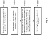
Fig. 2 is a flow chart showing operation of acontrol section 130 relating to a first mode of control. -
Fig. 3 is a flow chart showing operation of acontrol section 130 relating to a second mode of control. -
Fig. 4 is a flow chart showing operation of acontrol section 130 relating to a third mode of control. -
Fig. 5 is a figure showing a construction of aflavor inhaler 500 according to an embodiment. -
Fig. 6 is a figure showing an aerosol flow path of theflavor inhaler 500. -
Fig. 7 is a figure showing a construction of aflavor inhaler 700 according to another embodiment. -
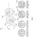
Fig. 8 is a figure showing an example of a construction of a flowrate adjustment mechanism 730 and operation thereof. -
Fig. 9 is a figure showing another example of a construction of a flowrate adjustment mechanism 730 and operation thereof. - In the following description, embodiments of the present invention will be explained with reference to the figures.
-
Fig. 1 is a figure showing a construction of aflavor inhaler 100 according to an embodiment of the present invention. It should be reminded thatFig. 1 shows respective elements included in theflavor inhaler 100 in a schematic and conceptual manner, and does not show precise arrangement, shapes, sizes, positional relationship, and so on of the respective elements and theflavor inhaler 100. Regarding constructions and appearances of flavor inhalers and respective elements, which are more realistic and closer to actual examples, they will be explained later with reference toFigs. 5-9 . - As shown in
Fig. 1 , theflavor inhaler 100 comprises areservoir 102, an atomizingsection 104, aflavor source 106, amouthpiece member 108, anaerosol flow path 110, and a flowrate adjustment mechanism 112. Regarding these elements in theflavor inhaler 100, some of them may be integrated into a detachable cartridge. For example, theflavor source 106 only may be constructed as a cartridge attachable/detachable to/from a main body of theflavor inhaler 100, the atomizingsection 104 and thereservoir 102 may be constructed as a cartridge attachable/detachable to/from abattery 114, and theflavor source 106, thereservoir 102, and the atomizingsection 104 may be integrated into a cartridge attachable/detachable to/from thebattery 114. - The
reservoir 102 holds an aerosol source. For example, thereservoir 102 comprises fibrous or porous material, and holds the aerosol source, which is in the form of fluid, by spaces between fibers or in pores in the porous material. Thereservoir 102 may be constructed as a tank for storing fluid. The aerosol source may be, for example, a liquid such as glycerin or propylene glycol. Thereservoir 102 comprises a construction for allowing replenishment of the aerosol source, or a construction for allowing replacement of the reservoir itself when the aerosol source is exhausted. - The atomizing
section 104 is constructed to generate aerosol by atomizing the aerosol source. The atomizingsection 104 generates the aerosol when inhaling action is detected by an inhaling sensor 122 (for example, a pressure sensor for detecting change in pressure in an air taking-inflow path 116 or theaerosol flow path 110, or a manipulation button which can be manipulated by a user). For example, a wick is arranged for connection between thereservoir 102 and theatomizing section 104. A part of the wick extends to the inside of thereservoir 102 and is in contact with the aerosol source. Another part of the wick extends toward theatomizing section 104. The aerosol source is sent from thereservoir 102 to theatomizing section 102 by capillary effect in the wick. Theatomizing section 104 comprises, for example, a heater which is electrically connected to thebattery 114. The heater is arranged to be in contact with the wick, and the aerosol source sent through the wick is heated to be atomized. Another example of theatomizing section 104 may be an ultrasonic-type atomizer which atomizes the aerosol source by ultrasonic vibration. The air taking-inflow path 116 is connected to theatomizing section 104, and the air taking-inflow path 116 leads to the outside of theflavor inhaler 100. The aerosol generated in theatomizing section 104 is mixed with air, which is taken via the air taking-inflow path 116, and sent to theaerosol flow path 110. - The
flavor source 106 is a unit for providing aerosol with flavor. Theflavor source 106 is arranged in a middle position on theaerosol flow path 110. A fluid comprising a mixture of air and the aerosol generated in the atomizing section 104 (in the following description, it should be reminded that this fluid mixture may simply be referred to as aerosol) flows through theaerosol flow path 110 to a mouthpiece (the mouthpiece member 108). That is, in the point of view of the flow of the aerosol, theflavor source 106 is arranged in a position downstream theatomizing section 104. In other words, in theaerosol flow path 110, the position of theflavor source 106 is closer to the mouthpiece than the position of theatomizing section 104. In this manner, the aerosol generated in theatomizing section 104 passes through theatomizing section 104 and arrives at the mouthpiece. When the aerosol passes through theflavor source 106, a flavor component from theflavor source 106 is added to the aerosol. For example, theflavor source 106 may be that which originates from tobacco, such as shredded tobacco, a product which is made by processing raw material comprising tobacco to have a granular form, a sheet form, or a powder form, or the like, or that which does not originate from tobacco, such as a product made by use of a plant other than tobacco (for example, mint, a herb, and so on). For example, theflavor source 106 comprises a nicotine component. Theflavor source 106 may comprise a flavor component such as menthol. Note that, in addition to having theflavor source 106, it is possible to make thereservoir 102 to have a material comprising a flavor component. For example, theflavor inhaler 100 may be constructed in such a manner that theflavor source 106 holds flavor material which originates from tobacco and thereservoir 102 comprises flavor material which does not originate from tobacco. - The
mouthpiece member 108 is positioned at an end of the aerosol flow path 110 (i.e., positioned downstream the flavor source 106), and constructed to make theaerosol flow path 110 to be opened toward the outside of theflavor inhaler 100. A user takes air including the aerosol into the mouth by holding themouthpiece member 108 in the user's mouth and inhaling it. - The
aerosol flow path 110 is a tubular structure for sending the fluid mixture comprising air and the aerosol generated in theatomizing section 104 to the mouthpiece. As shown inFig. 1 , theaerosol flow path 110 comprises a sharedflow path 110C, afirst flow path 110A, and asecond flow path 110B. The sharedflow path 110C connects between theatomizing section 104 and the flowrate adjustment mechanism 112. The aerosol generated in theatomizing section 104 is sent, together with air, to the sharedflow path 110C, and to the flowrate adjustment mechanism 112 through the sharedflow path 110C. The flowrate adjustment mechanism 112 and themouthpiece member 108 are connected by two paths, specifically, thefirst flow path 110A and thesecond flow path 110B. Theflavor source 106 is arranged in a position in the middle of thefirst flow path 110A. That is, thefirst flow path 110A connects between the flowrate adjustment mechanism 112 and theflavor source 106, and connects between theflavor source 106 and themouthpiece member 108. On the other hand, thesecond flow path 110B connects between the flowrate adjustment mechanism 112 and themouthpiece member 108 in a direct manner, i.e., without passing through theflavor source 106. In this manner, in the part downstream the flowrate adjustment mechanism 112, the fluid mixture comprising air and the aerosol is divided to flow through thefirst flow path 110A and thesecond flow path 110B to be sent to themouthpiece member 108. A part of the aerosol flowing through thefirst flow path 110A passes through theflavor source 106 and a flavor component is added thereto, and, thereafter, the part of the aerosol is led to the mouthpiece. Another part of the aerosol flowing through thesecond flow path 110B does not pass through theflavor source 106; thus, the other part of the aerosol is led to the mouthpiece without addition of the flavor component included in theflavor source 106. The aerosol flown through thefirst flow path 110A and the aerosol flown through thesecond flow path 110B are flown into each other at themouthpiece member 108 and inhaled by a user. - In the
flavor inhaler 100 shown as an example inFig. 1 , the flowrate adjustment mechanism 112 is arranged in a position at a branching point in theaerosol flow path 110 where the sharedflow path 110C is divided into thefirst flow path 110A and thesecond flow path 110B. That is, the starting point (the end of the upstream side) of thesecond flow path 110B is indirectly connected to thefirst flow path 110A via the flowrate adjustment mechanism 112. However, the arrangement of the flowrate adjustment mechanism 112 is not limited to that explained above. For example, the flowrate adjustment mechanism 112 may be positioned at a position in the middle of thefirst flow path 110A (i.e., a position downstream the branching point), or a position in the middle of thesecond flow path 110B (i.e., a position downstream the branching point). In other words, the starting point of thesecond flow path 110B may be directly connected to thefirst flow path 110A at the branching point. In addition, although thefirst flow path 110A and thesecond flow path 110B are joined at themouthpiece member 108 in theflavor inhaler 100 shown as an example inFig. 1 , such a construction is optional. For example, there may be a construction wherein an end (the downstream-side end) of thesecond flow path 110B is connected to the flavor source 106 (for example, at a position around the center, in terms of direction of flow of the aerosol, of the flavor source 106) instead of themouthpiece member 108, so that the aerosol flowing through thesecond flow path 110B passes through a part of the flavor source 106 (for example, a downstream-side half of the flavor source 106). Further, although thefirst flow path 110A only is provided with theflavor source 106 in theflavor inhaler 100 shown as an example inFig. 1 , a flavor source different from the flavor source 106 (for example, a flavor source which can add a flavor component, which is different from the component which can be added by theflavor source 106, to the aerosol) may further be added to thesecond flow path 110B. - The flow
rate adjustment mechanism 112 is constructed in such a manner that it can adjust the ratio between the flow rate of the fluid flowing from the sharedflow path 110C to thefirst flow path 110A and that of the fluid flowing to thesecond flow path 110B. As explained above, the fluid flowing through theaerosol flow path 110 is a fluid mixture comprising the aerosol generated in theatomizing section 104 and the air taken from the air taking-inflow path 116. It is supposed that the flow rate of air and the flow rate of aerosol flowing through the sharedflow path 110C are QT and MT, the flow rate of the air and the flow rate of the aerosol flowing through thefirst flow path 110A are Q1 and M1, and the flow rate of the air and the flow rate of the aerosol flowing through thesecond flow path 110B are Q2 and M2, respectively. In this regard, there are conditions that QT=Q1+Q2 and MT=M1+M2. The flowrate adjustment mechanism 112 is constructed in such a manner that it can adjust the ratio β between the flow rate of the air flowing into thefirst flow path 110A and that of the air flowing into thesecond flow path 110B. The air flow rate ratio β may be defined as the amount of air flowing through thefirst flow path 110A to the amount of the whole air flowing through the aerosol flow path 110 (i.e., β=Q1/QT), or the amount of air flowing through thefirst flow path 110A to the amount of air flowing through thesecond flow path 110B (i.e., β=Q1/Q2). In a similar manner, the flow rate ratio a of the aerosol is defined as α=M1/MT or α=M1/M2. Usually, the air flow rate ratio β is equal to the aerosol flow rate ratio α. The air flow rate ratio β (and the aerosol flow rate ratio α) is dependent on air-flow resistance of each of thefirst flow path 110A and thesecond flow path 110B, and the air-flow resistance is dependent on the length and the cross-sectional area, the degree of bending, the shapes of a branching part and a junction part, and so on of the flow path. The flowrate adjustment mechanism 112 comprises, for example, a structure by which a cross-sectional area of a flow path of at least one of thefirst flow path 110A and thesecond flow path 110B can be changed. Note that examples of tangible structures of the flowrate adjustment mechanism 112 will be explained later with reference toFigs. 5-9 . - The
flavor inhaler 100 can improve the degree of freedom of control of the amount of aerosol and the amount of flavor to be inhaled by a user, by having the flowrate adjustment mechanism 112 explained above. For example, by changing a cross-sectional area of a flow path of one or both of thefirst flow path 110A and thesecond flow path 110B, the air flow rate ratio β (and the aerosol flow rate ratio α) is changed, and, in response thereto, change in the amount of aerosol flowing through thefirst flow path 110A and the amount of aerosol flowing through thesecond flow path 110B occur. Further, change in the amount of aerosol flowing through thefirst flow path 110A leads to change in the amount of the flavor component supplied to a user. Thus, the user can freely adjust the ratio between the aerosol and the flavor component which are to be inhaled. - The
flavor inhaler 100 comprises auser setting section 150 which allows a user to set at least one of the air flow rate ratio β of thefirst flow path 110A and thesecond flow path 110B controlled by the flowrate adjustment mechanism 112 and the amount of aerosol to be generated in theatomizing section 104. For example, theuser setting section 150 is constructed as a button, a switch, a control, or the like which can be physically manipulated by a user. As another example, theuser setting section 150 may be constructed as a communication interface (for example, a USB terminal or a wireless interface) which receives an instruction from a user via communication connection with an external computer. In the case that the air flow rate ratio β of the flowrate adjustment mechanism 112 is set by user manipulation via theuser setting section 150, the flowrate adjustment mechanism 112 performs operation in accordance with the setting. In the case that the amount of aerosol to be generated in theatomizing section 104 is set by user manipulation via theuser setting section 150, theatomizing section 104 performs operation in accordance with the setting. Setting of theuser setting section 150 may be that for one of the flowrate adjustment mechanism 112 and theatomizing section 104, or that for changing operation of both the flowrate adjustment mechanism 112 and theatomizing section 104 at the same time. - In the case that a user wishes to inhale a more (or less) amount of flavor without changing the amount of aerosol to be inhaled, the user performs setting of the
user setting section 150 to change the air flow rate ratio of the flowrate adjustment mechanism 112 to make the more (or less) amount of aerosol to be passed through thecartridge 106, and the user does not change the setting of theatomizing section 104. As a result thereof, while a certain amount of aerosol is generated in theatomizing section 104, the air flow rate ratio of thefirst flow path 110A and thesecond flow path 110B controlled by the flowrate adjustment mechanism 112 is changed according to the user manipulation. Thus, theflavor inhaler 100 can change the amount of flavor supplied to the user, while maintaining the amount of aerosol supplied to the user to be constant. Another example is that, in the case that theuser setting section 150 is set for changing one of the air flow rate ratio of the flowrate adjustment mechanism 112 and the amount of aerosol to be generated in theatomizing section 104, the operation of another of the flowrate adjustment mechanism 112 and theatomizing section 104 may be changed according to controlling (a first mode of control and a second mode od control) by acontrol section 130 which will be explained later. - The
flavor inhaler 100 according to the present embodiment further comprises thecontrol section 130 and amemory 140. The control section is an electronic circuit module constructed as a microprocessor or a microcomputer, and is programmed to control operation of theflavor inhaler 100 according to computer-executable instructions stored in thememory 140. The memory comprises an information storing medium such as a ROM, a RAM, a flash memory, or the like. Thememory 140 stores, in addition to the computer-executable instructions, setting data which are necessary for controlling theflavor inhaler 100. - In rough outline, the
control section 130 is constructed to control operation of at least one of the flowrate adjustment mechanism 112 and theatomizing section 104. In a first mode of operation, thecontrol section 130 controls the air flow rate ratio β between thefirst flow path 110A and thesecond flow path 110B, by controlling the flowrate adjustment mechanism 112 based on the amount MT of aerosol generated in theatomizing section 104. In a second mode of operation, thecontrol section 130 controls the amount MT of aerosol generated in theatomizing section 104, based on the air flow rate ratio β between thefirst flow path 110A and thesecond flow path 110B controlled by the flowrate adjustment mechanism 112. In each of the fist and second modes of operation, the state of operation of one of theatomizing section 104 and the flowrate adjustment mechanism 112 affects operation of another of them. Further, in a third mode of operation, thecontrol section 130 performs control based on an accumulated value of the amounts of aerosol generated in theatomizing section 104. Details of control of each mode will be explained in the following description. -
Fig. 2 is a flow chart showing operation of acontrol section 130 relating to the first mode of control. In step S202, thecontrol section 130 determines the amount MT of aerosol to be generated in theatomizing section 104. Determining the amount MT of aerosol to be generated includes reading, from thememory 140, a set value of the amount of aerosol to be generated in the atomizing section 104 (a first example), and estimating the amount of aerosol, which will be actually generated, based on electric energy supplied to the heater of the atomizing section 104 (a second example). The amount MT of aerosol generated in theatomizing section 104 is equal to a set value of the amount of aerosol that should be generated in the atomizing section 104 (an instructed value for the atomizing section 104) in the first example, and is equal to an estimate value of the amount of aerosol that is expected to be generated in theatomizing section 104 in the second example. - In the first example, an initial set value of the amount of aerosol, that should be generated by the
atomizing section 104 when starting operation of the flavor inhaler 100 (when starting inhaling action), is stored in thememory 140 in advance. Also, in the case that the amount of aerosol that should be generated by theatomizing section 104 is newly set via theuser setting section 150, the initial set value of the amount of aerosol to be generated, that is stored in thememory 140, is updated by the new set value. Thecontrol section 130 obtains an initial set value of the amount of aerosol to be generated or a new set value from thememory 140, and decides to use the initial set value or the new set value as the amount MT of aerosol to be generated in theatomizing section 104. - In the second example, the
control section 130 estimates the amount of aerosol, which will be generated in theatomizing section 104, based on the electric energy supplied to the heater of theatomizing section 104. Usually, the amount of aerosol generated in theatomizing section 104 is determined according to energy supplied to the aerosol source. For example, relationship between the electric energy supplied to the heater of theatomizing section 104 and the estimated amounts of aerosol generated from the aerosol source when the heater is heated by the electric energy is stored in thememory 140 in advance. Thecontrol section 130 observes the electric energy supplied from thebattery 114 to the heater of theatomizing section 104, obtains an estimate value of the amount of aerosol to be generated, that corresponds to an observed value, from thememory 140, and decides to use the obtained estimate value as the amount MT of aerosol generated in theatomizing section 104. - Note that, regarding the electric energy for the heater, the electric energy may be calculated by measuring a resistance value of the heater, a voltage applied to the heater, and the time of electric conduction to the heater, and using the measured values, or the electric energy may be estimated by measuring a voltage applied to the heater and the time of electric conduction to the heater, under an assumption that the resistance value of the heater does not change, and using the measured values. Under the condition that electric power supplied to the heater per unit time is constant, the
control section 130 may observe the time of electric conduction to the heater (for example, electric conduction time per single inhaling action), instead of observing the electric energy (= electric power * electric conduction time) supplied to the heater. In the case that it is necessary to consider voltage reduction of thebattery 114, thecontrol section 130 observes both instantaneous electric power supplied to the heater and electric conduction time. In this regard, for compensating for voltage reduction of thebattery 114, a duty ratio may be adjusted to extend an electric conduction cycle (an ON period), in pulse width modulation (PWM) control for the heater. - In step S204, the
control section 130 determines the amount M1 of aerosol to be passed through theflavor source 106. For example, reference values of amounts of aerosol which are required for taking out desired amounts of flavor to be included in the aerosol are stored in thememory 140 in advance. Thecontrol section 130 obtains a reference value, and decides to use it as the amount M1 of aerosol which should be passed through theflavor source 106. Theflavor inhaler 100 may be constructed in such a manner that there are plural types of cartridges which hold different flavor sources 160 and are replaceable. In such a case, theflavor inhaler 100 further comprises a mechanism for identifying the type of cartridge (i.e., the flavor source 106) presently installed, and thememory 140 may store different reference values of the amounts of aerosol for respective various flavor sources 160. Thecontrol section 130 obtains a reference value corresponding to the identifiedflavor source 106 from thememory 140, and decides to use the obtained reference value as the amount M1 of aerosol which should be passed through theflavor source 106. - Note that step S204 may be performed before performing step 202, or step S204 and step S202 may be performed at the same time (in parallel).
- In step S206, the
control section 130 determines the air flow rate ratio β of the flowrate adjustment mechanism 112, based on the amount MT of the aerosol generated in theatomizing section 104 and the amount M1 of the aerosol to be passed through theflavor source 106. When the amount MT of the aerosol generated in theatomizing section 104 is changed, thecontrol section 130 changes, in response to the change, the air flow rate ratio β of the flowrate adjustment mechanism 112. For example, in the case that the amount MT of the aerosol generated in theatomizing section 104 is made to be large, thecontrol section 130 changes the air flow rate ratio β of the flowrate adjustment mechanism 112 to have a small value, and, in the case that the amount MT of the aerosol generated in theatomizing section 104 is made to be large, thecontrol section 130 changes the air flow rate ratio β of the flowrate adjustment mechanism 112 to have a large value. For example, thecontrol section 130 uses the amount MT of the aerosol generated in theatomizing section 104 and the amount M1 of the aerosol to be passed through theflavor source 106 to determine the air flow rate ratio β of the flowrate adjustment mechanism 112 by use of following formula (1).
- In step S208, the
control section 130 controls the flowrate adjustment mechanism 112 in such a manner that the ratio Q1/QT of the flow rate Q1 of air flowing through thefirst flow path 110A to the total flow rate QT of air flowing through theaerosol flow path 110 coincides with the air flow rate ratio β determined in step S206. For example, thecontrol section 130 controls the air flow rate ratio of the flowrate adjustment mechanism 112 to have a desired value, by operating the flowrate adjustment mechanism 112 to change a cross-section area of the flow path of at least one of thefirst flow path 110A and thesecond flow path 110B. Thecontrol section 130 may detect, by use of aflow rate sensor 124, at least one of the flow rate Q1 of air flowing through thefirst flow path 110A and the flow rate Q2 of air flowing through thesecond flow path 110B, and performs feedback control of the air flow rate ratio of the flowrate adjustment mechanism 112 by use of the detected flow rate(s). The flowrate adjustment mechanism 112 is electrically connected to thebattery 114, and operates to change a cross-section area of the flow path of at least one of thefirst flow path 110A and thesecond flow path 110B in accordance with instructions from thecontrol section 130, for example. - As explained above, as a result that the
control section 130 performs the first mode of control, theflavor inhaler 100 operates in such a manner that the air flow rate ratio of the flowrate adjustment mechanism 112 is adjusted to correspond to the amount of aerosol generated in theatomizing section 104. - For example, at the time of start of the operation of the
flavor inhaler 100, theatomizing section 104 generates a certain amount of aerosol in accordance with an initial set value of the amount of aerosol to be generated, wherein the initial set value has been stored in thememory 140 in advance. Thecontrol section 130 obtains an initial set value of the amount of aerosol to be generated and a reference value of the amount of aerosol to be passed through theflavor source 106 from thememory 140, calculates the air flow rate ratio β of the flowrate adjustment mechanism 112, based on these values and the above formula (1), and controls the flowrate adjustment mechanism 112 in accordance with the calculated air flow rate ratio β. As a result thereof, the aerosol of the amount M1 flows through thefirst flow path 110A and passes through theflavor source 106. - Further, in the case that setting of the amount of aerosol to be generated is changed via the
user setting section 150, theatomizing section 104 generates the amount of aerosol indicated by the changed set value. Thecontrol section 130 obtains, from thememory 140, the updated set value of the amount of aerosol to be generated and the reference value of the amount of aerosol to be passed through theflavor source 106, calculates the air flow rate ratio β of the flowrate adjustment mechanism 112 based on the above obtained values and above formula (1), and controls the flowrate adjustment mechanism 112 in accordance with the calculated air flow rate ratio β. As a result thereof, the amount of aerosol that is different from the amount at the time of start of operation of theflavor inhaler 100 is generated in theatomizing section 104, and the amount M1 of the aerosol that is equal to the amount at the time of start of operation of theflavor inhaler 100 is sent to flow though thefirst flow path 110A and passed through theflavor source 106. - Also, in the case that the electric energy supplied from the
battery 114 to the heater of theatomizing section 104 changes (for example, due to voltage reduction of thebattery 114, or the like), the amount of aerosol generated in theatomizing section 104 also changes. Thecontrol section 130 detects the electric energy supplied to theatomizing section 104, obtains, from thememory 140, the value of the amount of aerosol to be generated, which corresponds to the above detected value, and the reference value of the amount of aerosol sent to be passed through theflavor source 106, calculates the air flow rate ratio β of the flowrate adjustment mechanism 112 based on the above obtained values and above formula (1), and controls the flowrate adjustment mechanism 112 in accordance with the calculated air flow rate ratio β. As a result thereof, the amount M1 of the aerosol that is equal to the amount at the time of start of operation of theflavor inhaler 100 is sent to flow though thefirst flow path 110A and passed through theflavor source 106, independent of change in the amount of electric power supplied to theatomizing section 104. - In this manner, in the example of the first mode of control, the
control section 130 controls the air flow rate ratio of the flowrate adjustment mechanism 112 in such a manner that the amount of the aerosol flowing though thefirst flow path 110A is made to be constant. Thus, theflavor inhaler 100 can supply a constant amount of flavor to a user, independent of the amount of aerosol generated in the atomizing section. In this regard, the first mode of control is not limited to controlling for precisely maintaining the values of the amounts of the aerosol and the flavor to be the same values. For example, in the case that the amount of aerosol generated in theatomizing section 104 is increased or decreased, change in the amount of the aerosol flowing though thefirst flow path 110A can be reduced, compared with the degree of change in the amount of the generated aerosol, by performing control to make the air flow rate ratio β of the flow rate adjustment mechanism 112 (the ratio of distribution to thefirst flow path 110A) smaller or larger to some extent. -
Fig. 3 is a flow chart showing operation of thecontrol section 130 relating to a second mode of control. In step S302, thecontrol section 130 calculates the air flow rate ratio β of the flowrate adjustment mechanism 112, based on a state of operation of the flow rate adjustment mechanism 112 (for example, the cross-section areas of flow paths of thefirst flow path 110A and thesecond flow path 110B). For example, the flowrate adjustment mechanism 112 is constructed in such a manner that thefirst flow path 110A has a flow-path cross-section area that is fixed, and thesecond flow path 110B has a flow-path cross-section area that can be varied in accordance with user manipulation via theuser setting section 150. The flow-path cross-section area of thesecond flow path 110B is represented by a ratio (a degree of opening) X to the flow-path cross-section area when thesecond flow path 110B is fully opened. The degree of opening X of thesecond flow path 110B is a parameter representing the state of operation of the flowrate adjustment mechanism 112. Relationship between the degrees of opening X of thesecond flow path 110B and the air flow rate ratios β of the flowrate adjustment mechanism 112 is stored in thememory 140 in advance. Thecontrol section 130 detects the degree of opening X of thesecond flow path 110B, and obtains, from thememory 140, the value of the air flow rate ratio β of the flowrate adjustment mechanism 112 corresponding to the above detected value. For example, a variable resistor, which operates in response to change in the flow-path cross-section area, is attached to thesecond flow path 110B, and thecontrol section 130 can detect the degree of opening X of thesecond flow path 110B based on a resistance value of the variable resistor. In another example, an optical sensor for detecting the degree of opening X may be used. The flowrate adjustment mechanism 112 may be constructed in such a manner that both thefirst flow path 110A and thesecond flow path 110B have flow-path cross-section areas that can be varied in accordance with user manipulation via theuser setting section 150. In such a case, relationship between the degrees of opening X1 of thefirst flow path 110A and the degrees of opening X2 of thesecond flow path 110B and the air flow rate ratios β of the flowrate adjustment mechanism 112 is stored in thememory 140 in advance. Thecontrol section 130 detects the degree of opening X1 of thefirst flow path 110A and the degree of opening X2 of thesecond flow path 110B, and obtains, from thememory 140, the value of the air flow rate ratio β of the flowrate adjustment mechanism 112 corresponding to the above detected values. - In step S304, the
control section 130 determines the amount M1 of aerosol to be passed through theflavor source 106. This step S304 is the same as step S204 in the above first mode of control. Also, similar to the case of the first mode of operation, step S304 may be performed before performingstep 302, or step S304 and step S302 may be performed at the same time (in parallel). - In step S306, the
control section 130 determines the amount MT of aerosol to be generated in theatomizing section 104, based on the air flow rate ratio β of the flowrate adjustment mechanism 112 and the amount M1 of aerosol to be passed through theflavor source 106. When the air flow rate ratio β of the flowrate adjustment mechanism 112 is changed in accordance with user manipulation via theuser setting section 150, thecontrol section 130 responds thereto to change the amount MT of aerosol generated in theatomizing section 104. For example, in the case that the air flow rate ratio β of the flowrate adjustment mechanism 112 is changed to make it large by user manipulation, thecontrol section 130 makes the amount MT of aerosol generated in theatomizing section 104 small, and, in the case that the air flow rate ratio β of the flowrate adjustment mechanism 112 is changed to make it small, thecontrol section 130 makes the amount MT of aerosol generated in theatomizing section 104 large. For example, thecontrol section 130 uses the air flow rate ratio β of the flowrate adjustment mechanism 112 and the amount M1 of the aerosol to be passed through theflavor source 106 to determine the amount MT of aerosol to be generated in theatomizing section 104 by use of following formula (2).
- In step S308, the
control section 130 controls theatomizing section 104 in such a manner that the amount of aerosol to be generated in theatomizing section 104 becomes equal to the amount MT of aerosol determined in step S306. Thecontrol section 130 controls the amount of aerosol to be generated in theatomizing section 104 to have a desired value, by changing the electric energy supplied from thebattery 114 to the heater of theatomizing section 104. For example, relationship between the electric energy supplied to the heater of theatomizing section 104 and the amounts of aerosol generated when the heater is heated by the electric energy is stored in thememory 140 in advance. Thecontrol section 130 obtains the value of electric energy, which is to be suppled to the heater, corresponding to the amount MT of aerosol determined in step S306 from thememory 140, and performs control in such a manner that the electric energy suppled to the heater of theatomizing section 104 coincides with the above obtained value. - As explained above, as a result that the
control section 130 performs the second mode of control, theflavor inhaler 100 operates in such a manner that the amount of aerosol generated in theatomizing section 104 is adjusted in accordance with the air flow rate ratio of the flowrate adjustment mechanism 112. - For example, when starting operation of the
flavor inhaler 100, the flowrate adjustment mechanism 112 has already set in such a manner that the degree of opening X of thesecond flow path 110B takes a predetermine value. Thecontrol section 130 detects the degree of opening X of thesecond flow path 110B, obtains, from thememory 140, the value of the air flow rate ratio of the flowrate adjustment mechanism 112, which corresponds to the above detected value, and the reference value of the amount of aerosol to be passed through theflavor source 106, calculates the amount MT of aerosol to be generated in theatomizing section 104 based on the above values and above formula (2), and controls theatomizing section 104 in accordance with the above calculated amount MT of aerosol to be generated. As a result thereof, the aerosol of the amount MT flows through thefirst flow path 110A and passes through theflavor source 106. - Further, in the case that the air flow rate ratio of the flow
rate adjustment mechanism 112 is changed via theuser setting section 150, thecontrol section 130 detects the changed degree of opening X of thesecond flow path 110B, obtains, from thememory 140, the value of the air flow rate ratio of the flowrate adjustment mechanism 112, which corresponds to the new degree of opening, and the reference value of the amount of aerosol to be passed through theflavor source 106, calculates the amount MT of aerosol to be generated in theatomizing section 104 based on the above values and above formula (2), and controls theatomizing section 104 in accordance with the above calculated amount MT of aerosol to be generated. As a result thereof, the amount of aerosol that is different from the amount at the time of start of operation of theflavor inhaler 100 is generated in theatomizing section 104, and the amount M1 of the aerosol that is equal to the amount at the time of start of operation of theflavor inhaler 100 is sent to flow though thefirst flow path 110A and passed through theflavor source 106. - In this manner, in the example of the second mode of control, the
control section 130 controls the amount of aerosol to be generated in theatomizing section 104 in response to change in the air flow rate ratio of the flowrate adjustment mechanism 112, that is made by user manipulation, in such a manner that the amount of the aerosol flowing though thefirst flow path 110A is made to be constant. Thus, theflavor inhaler 100 can supply a constant amount of flavor to a user, independent of the state of operation of the flowrate adjustment mechanism 112. In this regard, the second mode of control is not limited to controlling for precisely maintaining the values of the amounts of the aerosol and the flavor to be the same values. For example, in the case that the air flow rate ratio of the flow rate adjustment mechanism 112 (the ratio of distribution to thefirst flow path 110A) is made larger or smaller by user manipulation applied to the flowrate adjustment mechanism 112, change in the amount of the aerosol flowing though thefirst flow path 110A can be reduced, by performing control to make the amount of aerosol to be generated in theatomizing section 104 smaller or larger to some extent. -
Fig. 4 is a flow chart showing operation of thecontrol section 130 relating to a third mode of control. In step S402, thecontrol section 130 calculates an accumulated value of the amounts of aerosol generated in theatomizing section 104. As explained above, usually, the amount of aerosol to be generated is determined based on energy to be supplied to the aerosol source. For example, relationship between the electric energy supplied to the heater of theatomizing section 104 and the amounts of aerosol generated from the aerosol source when the heater is heated by the electric energy is stored in thememory 140 in advance. Thecontrol section 130 observes, over time, the electric energy (= electric power * electric conduction time) supplied from thebattery 114 to the heater of theatomizing section 104, obtains the values of amounts of generated aerosol that correspond to the above observed values, respectively, and adds the above obtained values to thereby obtain, in an estimation manner, an accumulated value of the amounts of the aerosol generated in the atomizing section. In the case that it is necessary to consider voltage reduction of thebattery 114, thecontrol section 130 observes both instantaneous electric power supplied to the heater and electric conduction time. Under the condition that electric power supplied to the heater per unit time is constant, thecontrol section 130 may observe time of electric conduction to the heater instead of observing electric energy supplied to the heater, and obtain the accumulated value of the amounts of generated aerosol based on the accumulated value of the electric conduction time. Note that the accumulated value of the amounts of aerosol may be that during a single inhaling period, or the accumulated value of the amounts of aerosol of respective inhaling periods over plural inhaling periods. - In step S404, the
control section 130 calculates an accumulated value of the amounts of aerosol passed through thefirst flow path 110A. The amount of aerosol passed through thefirst flow path 110A can be calculated from the amount of aerosol generated in theatomizing section 104 and the air flow rate ratio (= the aerosol flow rate ratio) of the flowrate adjustment mechanism 112. Thecontrol section 130 observes, over time, the air flow rate ratios of the flow rate adjustment mechanism 112 (for example, the degrees of opening X), successively calculates the amounts of aerosol passed through thefirst flow path 110A, based on the air flow rate ratios at respective points in time and the corresponding amounts of generated aerosol at the respective points in time, that are successively obtained from thememory 140 in above step S402, and adds the above obtained values to thereby obtain an accumulated value of the amounts of aerosol passed through thefirst flow path 110A. Thecontrol section 130 may be constructed to calculate the accumulated value of the amounts of aerosol passed through thesecond flow path 110B, in a manner similar to that explained above. Note that step S404 is optional, thus, it may be omitted. - In step S406, the
control section 130 judges whether the accumulated value of the amounts of aerosol generated in theatomizing section 104 exceeds a first threshold value. If the accumulated value of the amounts of generated aerosol exceeds the first threshold value, the process proceeds to step S408, and, if not, the process returns to step S402. In the case that an accumulated value of the amounts of aerosol passed through thefirst flow path 110A is calculated in step S404, thecontrol section 130 may be constructed in such a manner that it judges whether the accumulated value of the amounts of aerosol passed through thefirst flow path 110A exceeds a predetermined threshold value that corresponds to the above first threshold value, instead of judging whether the accumulated value of the amounts of aerosol generated in theatomizing section 104 exceeds the above first threshold value. The judgment in step S406 may be performed at any timing such as that 1) after single inhaling action is completed, 2) during a predetermined time lag that is between a point in time when inhaling action is detected by the inhalingsensor 122 and a point in time when atomizing of aerosol is started, or 3) during inhaling action (during a period of electric conduction to the heater), for example. - In step S408, the
control section 130 performs control that is applied to theatomizing section 104 or the flowrate adjustment mechanism 112, for changing the amount of aerosol to be generated in theatomizing section 104 or the air flow rate ratio of the flowrate adjustment mechanism 112. For example, thecontrol section 130 controls theatomizing section 104 or the flowrate adjustment mechanism 112 for changing the amount of aerosol passing through thefirst flow path 110A. There may be a case that ability to release a flavor component of theflavor source 106 is gradually degraded due to flow of aerosol passing through it. For compensating for lowering of the amount of flavor released from theflavor source 106, control for increasing the amount of aerosol passing through thefirst flow path 110A is applied. In such a case, the first threshold value used in judgment performed in step S406 corresponds to an accumulated amount of aerosol that is sufficient for consuming a certain amount of the flavor component from theflavor source 106. For example, thecontrol section 130 controls theatomizing section 104 to increase the amount of aerosol to be generated in theatomizing section 104, without changing the air flow rate ratio of the flowrate adjustment mechanism 112, to thereby increase the amount of aerosol passing through thefirst flow path 110A. As another example, it may be possible to construct thecontrol section 130 in such a manner that it controls the flowrate adjustment mechanism 112 to make the air flow rate ratio of the flow rate adjustment mechanism 112 (the ratio of distribution to thefirst flow path 110A) large, without changing the amount of aerosol to be generated in theatomizing section 104, to thereby increase the amount of aerosol passing through thefirst flow path 110A. As a result thereof, theflavor inhaler 100 can suppress effect due to consumption of the flavor source, and supply a certain amount of flavor to a user. - In step S410, the
control section 130 judges whether the accumulated value of the amounts of aerosol generated in theatomizing section 104 exceeds a second threshold value. If the accumulated value of the amounts of generated aerosol exceeds the second threshold value, the process proceeds to step S412, and, if not, the process returns to first step S402. The second threshold value is set to a value larger than the above first threshold value. In the case that an accumulated value of the amounts of aerosol passed through thefirst flow path 110A is calculated in step S404, thecontrol section 130 may be constructed in such a manner that it judges whether the accumulated value of the amounts of aerosol passed through thefirst flow path 110A exceeds a predetermined threshold value that corresponds to the above second threshold value, instead of judging whether the accumulated value of the amounts of aerosol generated in theatomizing section 104 exceeds the above second threshold value. - In step S412, the
control section 130 performs control to stop supply of aerosol to theflavor source 106. For example, thecontrol section 130 controls the flowrate adjustment mechanism 112 in such a manner that it blocks communication between theatomizing section 104 and thefirst flow path 110A (for example, by setting the degree of opening X1 of thefirst flow path 110A to zero). Also, thecontrol section 130 may control the flowrate adjustment mechanism 112 in such a manner that it blocks communication between theatomizing section 104 and both thefirst flow path 110A and thesecond flow oath 110B. In a further example, thecontrol section 130 may control theatomizing section 104 in such a manner that supply of electric power from thebattery 114 to the heater of theatomizing section 104 is cut off. As a result thereof, theflavor inhaler 100 can prevent excessive supply of flavor to a user and supply of aerosol that does not contain sufficient amount of flavor. - In a manner similar to that in above step S406, the judgment in step S410 may be performed at any timing such as that 1) after single inhaling action is completed, 2) during a predetermined time lag that is between a point in time when inhaling action is detected by the inhaling
sensor 122 and a point in time when atomizing of aerosol is started, or 3) during inhaling action (during a period of electric conduction to the heater), for example. Regarding the timing in the above example, in the case that judgment in step S410 is performed at timing 1) after single inhaling action is completed, an unnatural feel sensed by a user can be suppressed, since the control performed in step S412 does not interrupt atomizing of aerosol during inhaling action of the user or does not block the flow path. - Note that the order of the judgment process in step S406 and the control process in step S408 following step S406, and the judgment process in step S410 and the control process in step S412 following step S410 may be changed between them and performed in the changed order.
- Next, more tangible constructions of the flavor inhalers will be explained.
-
Fig. 5 is a figure showing a construction of aflavor inhaler 500 according to an embodiment. Theflavor inhaler 500 has a shape which extends in a predetermined direction A that is a direction from a non-mouthpiece end to a mouthpiece end. As shown inFig. 5 , theflavor inhaler 500 comprises aninhaler body 510, amouthpiece member 520, and acartridge 530. Themouthpiece member 520 and thecartridge 530 correspond to themouthpiece member 108 and theflavor source 106 inFig. 1 , respectively. - A main body of the
flavor inhaler 500 comprises theinhaler body 510 which has a shape allowing thecartridge 530 to be connected thereto. Theinhaler body 510 comprises anatomizing unit 511 which atomizes an aerosol source without a burning process. Theinhaler body 510 further comprises a battery assembly, a control section, and a memory which are not shown in the figure. The battery assembly comprises a battery. The control section may be positioned in the inside of the battery assembly, for example. The battery, the control section, and the memory correspond to thebattery 114, thecontrol section 130, and thememory 140 inFig. 1 , respectively. - The
atomizing unit 511 comprises areservoir 511P, awick 511Q, and anatomizing section 511R. Thereservoir 511P holds an aerosol source. For example, thereservoir 511P is a porous medium comprising non-tobacco material such as a resin web and so on. Thewick 511Q sucks the aerosol source held in the reservoir S11P. For example, thewick 511Q comprises glass fibers. Theatomizing section 511R atomizes the aerosol source sucked by thewick 511Q. For example, theatomizing section 511R comprises a heating wire wound, with a predetermined pitch, around thewick 511Q. Thereservoir 511P and theatomizing section 511R correspond to thereservoir 102 and theatomizing section 104 inFig. 1 , respectively. - The
mouthpiece member 520 comprises a mouthpiece which is to be held in the user's mouth and constructed to be attachable/detachable to/from theinhaler body 510. For example, themouthpiece member 520 is attached to theinhaler body 510 in a screwing or mating manner. - The
cartridge 530 is an example of a flavor source unit which is constructed to be connectable to theinhaler body 510 which is a component of theflavor inhaler 500. Thecartridge 530 is arranged in a position closer to the mouthpiece side than the position of theatomizing unit 511, in the flow path of a gas (hereinafter, air) inhaled from the mouthpiece. In other words, it is not necessarily arrange, in terms of a physical space, thecartridge 530 in a position closer to the mouthpiece side than the position of theatomizing unit 511, and it is satisfactory if thecartridge 530 is arranged in a position closer to the mouthpiece side than the position of theatomizing unit 511 in the aerosol flow path which leads the aerosol generated in theatomizing unit 511 to the mouthpiece side. - Specifically, the
cartridge 530 comprises acartridge body 531, aflavor source 532, and a mesh 533 (amesh 533A and amesh 533B). - The
cartridge body 531 has a cylindrical shape which extends in the predetermined direction A. Thecartridge body 531 houses theflavor source 532. - The
flavor source 532 is arranged in a position closer to the mouthpiece side than the position of theatomizing unit 511 in the flow path of the air inhaled from the mouthpiece. Theflavor source 532 provides the aerosol generated in the aerosol source with fragrance inhaling taste. In other words, the flavor added to the aerosol by theflavor source 532 is supplied to the mouthpiece. - The
flavor source 532 comprises an ingredient piece which provides aerosol generated in theatomizing unit 511 with fragrance inhaling taste. Shredded tobacco or a product, which is made by processing raw material comprising tobacco to have a granular form, may be used as an ingredient piece which is a component of theflavor source 532. In this regard, theflavor source 532 may comprise a product which is made by processing raw material comprising tobacco to have a sheet form. Also, the ingredient piece, which is a component of theflavor source 532, may comprise a plant other than tobacco (for example, mint, a herb, and so on). Theflavor source 532 may be provided with flavor such as menthol or the like. - With respect to the
flavor source 532, themesh 533A is positioned to cover an opening of thecartridge body 531 at the non-mouthpiece side, and, with respect to theflavor source 532, themesh 533B is positioned to cover an opening of thecartridge body 531 at the mouthpiece side. Each of themesh 533A and themesh 533B has a degree of coarseness that is sufficient to prevent the ingredient piece, which is a component of theflavor source 532, from passing through the mesh. -
Fig. 6 is a figure showing an aerosol flow path of theflavor inhaler 500. Specifically,Fig. 6 is a schematic cross-section view showing an internal structure of theflavor inhaler 500 in a state that thecartridge 530 is housed in theinhaler body 510. - As shown in
Fig. 6 , theflavor inhaler 500 comprises anaerosol flow path 540 which guides the aerosol generated in theatomizing unit 511 to the mouthpiece side. In other words, in the state that thecartridge 530 is housed in theinhaler body 510, theaerosol flow path 540, which guides the aerosol generated in theatomizing unit 511 to the mouthpiece side, is formed. Theaerosol flow path 540 comprises afirst flow path 540A which guides the aerosol to the mouthpiece side via theflavor source 532, and asecond flow path 540B which is different from thefirst flow path 540A. Thesecond flow path 540B is that which guides the aerosol to the mouthpiece side without passing through theflavor source 532. Theaerosol flow path 540, thefirst flow path 540A, and thesecond flow path 540B correspond to theaerosol flow path 110, thefirst flow path 110A, and thesecond flow path 110B inFig. 1 , respectively. - In a cross section perpendicular to the predetermined direction A, the outer diameter of the
cartridge body 531 is smaller than the inner diameter of theinhaler body 510. Also, thesecond flow path 540B is formed between anouter surface 531A of thecartridge body 531 and aninner surface 510A of theinhaler body 510. Further, a branchingsection 545 for thefirst flow path 540A and thesecond flow path 540B is arranged at a position outside thecartridge body 531. - In this manner, the
first flow path 540A is formed inside thecartridge body 531, and thesecond flow path 540B is formed outside thecartridge body 531. - Note that the
first flow path 540A and thesecond flow path 540B have a shared flow path which is common to them. The above explained branchingsection 545 is formed in the shared flow path which is formed between the atomizingunit 511 and thecartridge 530. The shared flow path corresponds to the sharedflow path 110C inFig. 1 . - The branching
section 545 for thefirst flow path 540A and thesecond flow path 540B is provided with an orifice which is not shown in the figure. The orifice corresponds to the flowrate adjustment mechanism 112 inFig. 1 . The orifice is constructed in such a manner that it is controlled by the control section to change a cross-section area of a flow path of at least one of thefirst flow path 540A and thesecond flow path 540B. -
Fig. 7 is a figure showing a construction of aflavor inhaler 700 according to another embodiment. Theflavor inhaler 700 comprises abattery assembly 710, anatomizing section 720, a flowrate adjustment mechanism 730, acartridge 740, and amouthpiece member 750. Thebattery assembly 710 further comprises, within it, a battery, a reservoir, a control section, and a memory which are not shown in the figure. Generally, theflavor inhaler 700 has an elongated cylindrical shape as a whole. Thebattery assembly 710 is constructed to be attachable/detachable to/from theatomizing section 720. Theatomizing section 720, the flowrate adjustment mechanism 730, thecartridge 740, and themouthpiece member 750 correspond to theatomizing section 104, the flowrate adjustment mechanism 112, theflavor source 106, and themouthpiece member 108 inFig. 1 , respectively. Also, the battery, the reservoir, the control section, and the memory in thebattery assembly 710 correspond to thebattery 114, thereservoir 102, thecontrol section 130, and thememory 140 inFig. 1 , respectively. - The
flavor inhaler 700 further comprises anaerosol flow path 760. Theatomizing section 720, the flowrate adjustment mechanism 730, thecartridge 740, and themouthpiece member 750 are arranged in this order from an upstream side to a downstream side. In a state that theflavor inhaler 700 has been assembled (the general view inFig. 7 ), theaerosol flow path 760 connects between theatomizing section 720 at the upstream side and themouthpiece member 750 at the downstream side. Theaerosol flow path 760 comprises afirst flow path 760A and asecond flow path 760B. Thefirst flow path 760A comprises a hollow which has been bored though, in a longitudinal direction, a center part of the flowrate adjustment mechanism 730, and a hollow which has been bored through, in a longitudinal direction, a center part of thecartridge 740. Thesecond flow path 760B comprises a hollow which has been bored through, in a longitudinal direction, a peripheral part of the flowrate adjustment mechanism 730, and a hollow which has been bored through, in a longitudinal direction, a peripheral part of thecartridge 740. In the state that theflavor inhaler 700 has been assembled, the hollow in the center part of the flowrate adjustment mechanism 730 and the hollow in the center part of thecartridge 740 form an integrated continuous hollow which is afirst flow path 760A, and the hollow in the peripheral part of the flowrate adjustment mechanism 730 and the hollow in the peripheral part of thecartridge 740 form an integrated continuous hollow which is asecond flow path 760B. Thecartridge 740 holds a flavor source in a part of the hollow in the center part, i.e., a part which is a component of thefirst flow path 760A. The hollow in the peripheral part of thecartridge 740, i.e., the part which is a component of thesecond flow path 760B does not hold a flavor source. In this manner, the aerosol generated in theatomizing section 720 is divided to flow through thefirst flow path 760A and thesecond flow path 760B and supplied to themouthpiece member 750. A part (a first part) of the aerosol flown into thefirst flow path 760A passes through the flavor source in thecartridge 740 and is led to the mouthpiece. Another part (a second part) of the aerosol flown into thesecond flow path 760B is led to the mouthpiece without passing through the flavor source. The aerosol from thefirst flow path 760A and the aerosol from thesecond flow path 760B flow into each other at themouthpiece member 750 and the resultant aerosol is absorbed by a user. Theaerosol flow path 760, thefirst flow path 760A, and thesecond flow path 760B correspond to theaerosol flow path 110, thefirst flow path 110A, and thesecond flow path 110B inFig. 1 , respectively. -
Fig. 8 is a figure showing an example of a construction of a flowrate adjustment mechanism 730 and operation thereof. The flowrate adjustment mechanism 730 comprises afirst member 731A and asecond member 731B. Thefirst member 731A and thesecond member 731B have cylindrical shapes, and are arranged to be aligned on a shared center axis C. Both thefirst member 731A and thesecond member 731B, or one of them, are/is constructed in such a manner that they/it can be rotated about the center axis C as the axis of rotation. Thefirst member 731A and thesecond member 731B have hollows which have been bored through, in longitudinal directions, center parts thereof. In the state that theflavor inhaler 700 has been assembled, the hollows in the center parts of thefirst member 731A and thesecond member 731B form a part of thefirst flow path 760A. The shapes of cross sections, which are perpendicular to the center axis C, of the hollows in the center parts are circular, have the same size, and share the center axis C as that defining the centers thereof. Thus, when thefirst member 731A and thesecond member 731B are relatively rotated about the center axis C as the axis of rotation, the cross-section area of the flow path of thefirst flow path 760A does not change. Thefirst member 731A and thesecond member 731B also comprise hollows which have been bored through, in longitudinal directions, peripheral parts thereof, respectively. In the state that theflavor inhaler 700 has been assembled, the hollows in the peripheral parts of thefirst member 731A and thesecond member 731B form a part of thesecond flow path 760B. The shapes of cross sections, which are perpendicular to the center axis C, of the hollows in the peripheral parts are semicircular arch, as shown in the figure. Accordingly, the degree of overlap between the hollow in the peripheral part of thefirst member 731A and the hollow in the peripheral part of thesecond member 731B changes according to positional relationship between thefirst member 731A and thesecond member 731B. Thus, when thefirst member 731A and thesecond member 731B are relatively rotated about the center axis C as the axis of rotation, the cross-section area of the flow path of thesecond flow path 760B changes according to the degree of overlap between the hollows in the peripheral parts. - In this manner, the flow
rate adjustment mechanism 730 is constructed to be able to adjust the flow rate ratio of air (and aerosol) flowing through thefirst flow path 760A and thesecond flow path 760B, by changing the cross-section area of the flow path of thesecond flow path 760B by relatively rotating thefirst member 731A and thesecond member 731B. A user can freely adjust the air flow rate ratio of the flowrate adjustment mechanism 730 by holding, by use of a hand, thefirst member 731A or thesecond member 731B of the flowrate adjustment mechanism 730 and turning it about the axis C of rotation. In such a case, thefirst member 731A and thesecond member 731B function as a user setting section (theuser setting section 150 inFig. 1 ) for setting the air flow rate ratio of the flowrate adjustment mechanism 730. Note that a variable resistor, which is not shown in the figure, is attached to thefirst member 731A and thesecond member 731B, wherein the resistance value of the variable resistor changes according to rotation of thefirst member 731A and thesecond member 731B. The control section included in thebattery assembly 710 can detect the degree of opening X of thesecond flow path 110B based on the resistance value of the variable resistor, and use the detected degree of opening in the above explained second mode of control. -
Fig. 9 is a figure showing another example of a construction of the flowrate adjustment mechanism 730 and operation thereof. The flowrate adjustment mechanism 730 comprises afirst member 732A and asecond member 732B. Thesecond member 732B has a construction which is the same as that of thesecond member 731B in the example construction inFig. 8 . Thefirst member 732A has a construction which is the same as that of thefirst member 731A in the example construction inFig. 8 , except that the shape of the hollow formed in the peripheral part is different from that of thefirst member 731A in the example construction inFig. 8 . Specifically, thefirst member 732A comprises plural small hollows (five hollows in the example in the figure) which have been bored through, in a longitudinal direction, the peripheral part of thefirst member 732A. The plural hollows are positioned in an approximately half circle part of thefirst member 732A. Accordingly, when thefirst member 732A and thesecond member 732B are relatively rotated about the center axis C as the axis of rotation, the cross-section area of the flow path of thesecond flow path 760B changes according to the degree of overlap between the hollows in the peripheral part of thefirst member 732A and the hollow in the peripheral part of thesecond member 732B. Thus, the air flow rate ratio of the flowrate adjustment mechanism 730 is adjustable. - Although the embodiments of the present invention have been explained in the above description, the present invention is not limited to the embodiments, and the embodiments can be modified in various ways without departing from the scope of the gist of the present invention.
-
- 100
- Flavor inhaler
- 102
- Reservoir
- 104
- Atomizing section
- 106
- Flavor source
- 108
- Mouthpiece member
- 110
- Aerosol flow path
- 110A
- First flow path
- 110B
- Second flow path
- 110C
- Shared flow path
- 112
- Flow rate adjustment mechanism
- 114
- Battery
- 116
- Air taking-in flow path
- 122
- Inhaling sensor
- 124
- Flow rate sensor
- 130
- Control section
- 140
- Memory
- 150
- User setting section
Claims (25)
- A flavor inhaler comprising:an aerosol source;an atomizing section for atomizing the aerosol source for generating aerosol;a flavor source positioned downstream the atomizing section;a mouthpiece positioned downstream the flavor source;an aerosol flow path for guiding the aerosol generated in the atomizing section to the mouthpiece, wherein the aerosol flow path comprises a first flow path leading to the mouthpiece via the flavor source, and a second flow path which is different from the first flow path and has a starting point connected directly or indirectly to the first flow path; anda flow rate adjustment mechanism which can adjust a ratio between an air flow rate of the first flow path and an air flow rate of the second flow path.
- The flavor inhaler according to Claim 1, wherein the second flow path is a flow path which does not pass through the flavor source.
- The flavor inhaler according to Claim 1 or 2, wherein the flow rate adjustment mechanism is positioned at least in a part on the first flow path or the second flow path.
- The flavor inhaler according to one of Claims 1-3 comprising a control section for controlling operation of at least one of the flow rate adjustment mechanism and the atomizing section.
- The flavor inhaler according to Claim 4, wherein the control section is constructed to control the ratio between the air flow rate of the first flow path and the air flow rate of the second flow path, by controlling operation of the flow rate adjustment mechanism based on the amount of the aerosol generated in the atomizing section.
- The flavor inhaler according to Claim 5, wherein the amount of the aerosol to be generated in the atomizing section per predetermined time, at the time when inhaling action starts, is determined in advance; and the control section controls the air flow rate ratio, based on the predetermined amount of the aerosol to be generated per the predetermined time.
- The flavor inhaler according to Claim 5 or 6, wherein
the control section is further constructed to detect change in the amount of the aerosol to be generated in the atomizing section per the predetermined time, and
the control section controls the air flow rate ratio based on the changed amount of the aerosol to be generated per the predetermined time. - The flavor inhaler according to Claim 4, wherein the control section is constructed to control the amount of the aerosol to be generated in the atomizing section by controlling operation of the atomizing section based on the ratio between the air flow rate of the first flow path and the air flow rate of the second flow path.
- The flavor inhaler according to Claim 8, wherein the air flow rate ratio, at the time when inhaling action starts, is determined in advance; and the control section controls the amount of the aerosol to be generated in the atomizing section based on the predetermined air flow rate ratio.
- The flavor inhaler according to Claim 8 or 9, wherein
the control section is further constructed to detect change in the air flow rate ratio, and
the control section controls the amount of the aerosol to be generated in the atomizing section based on the changed air flow rate ratio. - The flavor inhaler according to Claim 10, wherein the control section determines the changed air flow rate ratio based on an operation state of the flow rate adjustment mechanism.
- The flavor inhaler according to one of Claims 4-11, wherein the control section controls at least one of the air flow rate ratio and the amount of the aerosol to be generated in the atomizing section, for making the amount of the aerosol passing through the first flow path to be constant.
- The flavor inhaler according to Claim 6, wherein the control section controls the atomizing section to change the predetermined amount of the aerosol to be generated in the atomizing section per the predetermined time, in the case that an accumulated value of the amounts of the aerosol generated in the atomizing section or an accumulated value of the amounts of the aerosol passed through the first flow path exceeds a first threshold value.
- The flavor inhaler according to Claim 9, wherein the control section controls the flow rate adjustment mechanism to change the predetermined air flow rate ratio, in the case that an accumulated value of the amounts of the aerosol generated in the atomizing section or an accumulated value of the amounts of the aerosol passed through the first flow path exceeds a first threshold value.
- The flavor inhaler according to one of Claims 4-14, wherein the control section is further constructed to block communication between the atomizing section and the first flow path or cut off supply of electric power to the atomizing section, in the case that an accumulated value of the amounts of the aerosol generated in the atomizing section or an accumulated value of the amounts of the aerosol passed through the first flow path exceeds a second threshold value.
- The flavor inhaler according to one of Claims 13-15, wherein the control section calculates the amount of the aerosol passed through the first flow path based on the air flow rate ratio and the amount of the aerosol generated in the atomizing section.
- The flavor inhaler according to one of Claims 5-7 and 13-16, wherein the control section calculates the amount of the aerosol generated in the atomizing section based on electric energy supplied to the atomizing section.
- The flavor inhaler according to one of Claims 1-17, wherein the flow rate adjustment mechanism comprises a mechanism for changing at least one of a cross-section area of at least a part of the first flow path and a cross-section area of at least a part of the second flow path.
- The flavor inhaler according to one of Claims 1-18, wherein
the flow rate adjustment mechanism comprises a first member and a second member;
at least one of the first flow path and the second flow path is formed by the first member and the second member; and
at least one of a cross-section area of at least a part of the first flow path and a cross-section area of at least a part of the second flow path is changed as a result of relative movement of the first member and the second member. - The flavor inhaler according to one of Claims 1-19 further comprising a battery assembly comprising a battery.
- The flavor inhaler according to Claim 20, wherein the battery assembly is attachable/detachable to/from the atomizing section.
- The flavor inhaler according to one of Claims 1-21, wherein the flow rate adjustment mechanism is electrically connected to the battery.
- The flavor inhaler according to one of Claims 1-22 further comprising a user setting section for allowing setting of at least one of the air flow rate ratio and the amount of the aerosol to be generated in the atomizing section.
- The flavor inhaler according to one of Claims 1-23 further comprising an inhaling sensor for detecting inhaling action.
- The flavor inhaler according to one of Claims 1-24, wherein the flow rate adjustment mechanism comprises a flow rate sensor for detecting an air flow rate of at least one of the first flow path and the second flow path.
Applications Claiming Priority (1)
| Application Number | Priority Date | Filing Date | Title |
|---|---|---|---|
| PCT/JP2016/071998 WO2018020599A1 (en) | 2016-07-27 | 2016-07-27 | Flavor inhaler |
Publications (3)
| Publication Number | Publication Date |
|---|---|
| EP3491945A1 true EP3491945A1 (en) | 2019-06-05 |
| EP3491945A4 EP3491945A4 (en) | 2020-07-15 |
| EP3491945B1 EP3491945B1 (en) | 2021-12-08 |
Family
ID=61017051
Family Applications (1)
| Application Number | Title | Priority Date | Filing Date |
|---|---|---|---|
| EP16910502.0A Active EP3491945B1 (en) | 2016-07-27 | 2016-07-27 | Flavor inhaler |
Country Status (9)
| Country | Link |
|---|---|
| US (1) | US20190142073A1 (en) |
| EP (1) | EP3491945B1 (en) |
| JP (1) | JP6704454B2 (en) |
| KR (1) | KR102248619B1 (en) |
| CN (1) | CN109475182B (en) |
| CA (1) | CA3031874C (en) |
| EA (1) | EA035415B1 (en) |
| TW (1) | TWI679942B (en) |
| WO (1) | WO2018020599A1 (en) |
Cited By (10)
| Publication number | Priority date | Publication date | Assignee | Title |
|---|---|---|---|---|
| WO2021224601A1 (en) * | 2020-05-04 | 2021-11-11 | Nicoventures Trading Limited | Aerosol provision system |
| EP3765134A4 (en) * | 2018-03-14 | 2021-12-15 | Buzzelet Development And Technologies Ltd | An apparatus and method for adminstring terpene- enriched vapors |
| WO2022017764A1 (en) * | 2020-07-22 | 2022-01-27 | Philip Morris Products S.A. | Aerosol generating device with odour inhibition assembly |
| EP3977876A1 (en) * | 2020-09-30 | 2022-04-06 | Japan Tobacco Inc. | Power supply unit for aerosol generation device, and aerosol generation device |
| WO2022148833A1 (en) * | 2021-01-07 | 2022-07-14 | Jt International S.A. | Vapour delivering assembly and associated aerosol generation assembly |
| WO2022123540A3 (en) * | 2020-12-11 | 2022-07-21 | Rai Strategic Holdings, Inc. | Sleeve for smoking article |
| EP3998884A4 (en) * | 2020-09-23 | 2022-08-10 | KT & G Corporation | Aerosol-generating apparatus |
| WO2023280878A1 (en) * | 2021-07-05 | 2023-01-12 | Philip Morris Products S.A. | Aerosol-generating device with resistance-to-draw modifying element |
| EP4147584A1 (en) * | 2021-09-10 | 2023-03-15 | Nerudia Limited | Aerosol delivery component |
| EP4147585A1 (en) * | 2021-09-10 | 2023-03-15 | Nerudia Limited | Aerosol delivery component |
Families Citing this family (22)
| Publication number | Priority date | Publication date | Assignee | Title |
|---|---|---|---|---|
| GB201717498D0 (en) | 2017-10-24 | 2017-12-06 | British American Tobacco Investments Ltd | Aerosol provision device |
| GB201717496D0 (en) | 2017-10-24 | 2017-12-06 | British American Tobacco Investments Ltd | A cartridge for an aerosol provision device |
| GB201719578D0 (en) * | 2017-11-24 | 2018-01-10 | British American Tobacco Investments Ltd | Apparatus, system and method for generating an inhalable medium |
| GB201805169D0 (en) * | 2018-03-29 | 2018-05-16 | Nicoventures Holdings Ltd | A control device for an electronic aerosol provision system |
| GB201812373D0 (en) * | 2018-07-30 | 2018-09-12 | Nicoventures Trading Ltd | Generation of an inhalable medium |
| EP3841897A4 (en) * | 2018-08-24 | 2021-08-04 | Japan Tobacco Inc. | Suction component generator, method for controlling suction component generator, and program therefor |
| JP7117390B2 (en) * | 2018-10-26 | 2022-08-12 | 日本たばこ産業株式会社 | Control unit, aerosol generator, method and program for controlling heater, and smoking article |
| CN112969376A (en) * | 2018-10-26 | 2021-06-15 | 日本烟草产业株式会社 | Control unit, aerosol-generating device, method and program for controlling a heater, and smoking article |
| AU2019410142A1 (en) * | 2018-12-21 | 2021-07-15 | Hexo Operations Inc. | Apparatus and methods for serial configurations of multi-chamber vaporization devices |
| GB201905425D0 (en) | 2019-04-17 | 2019-05-29 | Nicoventures Trading Ltd | Electronic aerosol provision device |
| US11395512B2 (en) * | 2019-05-13 | 2022-07-26 | Simrell Collection, Llc | Vaporizer cooling system with a mixing chamber |
| WO2021175754A1 (en) * | 2020-03-05 | 2021-09-10 | Jt International Sa | Flavour adjuster for an electronic cigarette |
| KR20210153329A (en) | 2020-06-10 | 2021-12-17 | 주식회사 케이티앤지 | Aerosol-generating system with customizable scent emitting function and operating method thereof |
| KR102535307B1 (en) | 2020-06-26 | 2023-05-22 | 주식회사 케이티앤지 | Aerosol generating apparatus and method for providing aerosol by using the aerosol generating apparatus |
| JP2022015341A (en) * | 2020-07-08 | 2022-01-21 | 日本たばこ産業株式会社 | Control unit of aerosol generation device |
| KR102553828B1 (en) * | 2020-07-13 | 2023-07-10 | 주식회사 케이티앤지 | Aerosol generating device |
| WO2022064560A1 (en) * | 2020-09-23 | 2022-03-31 | 日本たばこ産業株式会社 | Suction device, control device, and control method |
| CN112493547A (en) * | 2020-12-07 | 2021-03-16 | 深圳麦克韦尔科技有限公司 | Electronic atomization device |
| JPWO2022190211A1 (en) * | 2021-03-09 | 2022-09-15 | ||
| US20220330618A1 (en) * | 2021-04-19 | 2022-10-20 | Shenzhen Eigate Technology Co., Ltd. | Electronic cigarette |
| WO2023053201A1 (en) * | 2021-09-28 | 2023-04-06 | 日本たばこ産業株式会社 | Inhalation device, aerosol generation system, and control method |
| GB202205737D0 (en) * | 2022-04-20 | 2022-06-01 | Nicoventures Trading Ltd | Aerosol provision system and method |
Family Cites Families (12)
| Publication number | Priority date | Publication date | Assignee | Title |
|---|---|---|---|---|
| CA2683884C (en) * | 2007-04-18 | 2012-10-30 | Japan Tobacco Inc. | Smoking article |
| CN102389167B (en) * | 2011-09-28 | 2013-05-29 | 卓尔悦(常州)电子科技有限公司 | Replaceable general atomizing head |
| ES2635056T3 (en) * | 2012-10-26 | 2017-10-02 | Vectura Gmbh | Inhalation device for use in aerosol therapy |
| US20150351456A1 (en) * | 2013-01-08 | 2015-12-10 | L. Perrigo Company | Electronic cigarette |
| WO2014115324A1 (en) * | 2013-01-28 | 2014-07-31 | 日本たばこ産業株式会社 | Non-heating flavor suction device |
| US20150258288A1 (en) * | 2014-03-11 | 2015-09-17 | Voodoo Science Llc | Breathable Fluid Delivery System Including Exchangeable Fluid Permeable Cartridge |
| JP5660238B1 (en) | 2014-03-19 | 2015-01-28 | カシオ計算機株式会社 | Program calculator and program |
| US20150335070A1 (en) * | 2014-05-20 | 2015-11-26 | R.J. Reynolds Tobacco Company | Electrically-powered aerosol delivery system |
| PL2989912T3 (en) * | 2014-09-01 | 2020-01-31 | Fontem Holdings 1 B.V. | Electronic smoking device |
| KR101924744B1 (en) * | 2014-11-10 | 2018-12-03 | 니뽄 다바코 산교 가부시키가이샤 | Non-combusting flavor inhaler |
| GB201503411D0 (en) * | 2015-02-27 | 2015-04-15 | British American Tobacco Co | Apparatus and method for generating an inhalable medium, and a cartridge for use therewith |
| KR101609715B1 (en) * | 2015-05-26 | 2016-04-20 | 주식회사 승완 | Management system for electronic cigarette |
-
2016
- 2016-07-27 CA CA3031874A patent/CA3031874C/en active Active
- 2016-07-27 CN CN201680087939.3A patent/CN109475182B/en active Active
- 2016-07-27 JP JP2018530253A patent/JP6704454B2/en active Active
- 2016-07-27 KR KR1020197005279A patent/KR102248619B1/en active IP Right Grant
- 2016-07-27 EP EP16910502.0A patent/EP3491945B1/en active Active
- 2016-07-27 WO PCT/JP2016/071998 patent/WO2018020599A1/en unknown
- 2016-07-27 EA EA201990378A patent/EA035415B1/en not_active IP Right Cessation
-
2017
- 2017-07-14 TW TW106123649A patent/TWI679942B/en active
-
2019
- 2019-01-16 US US16/249,665 patent/US20190142073A1/en not_active Abandoned
Cited By (11)
| Publication number | Priority date | Publication date | Assignee | Title |
|---|---|---|---|---|
| EP3765134A4 (en) * | 2018-03-14 | 2021-12-15 | Buzzelet Development And Technologies Ltd | An apparatus and method for adminstring terpene- enriched vapors |
| WO2021224601A1 (en) * | 2020-05-04 | 2021-11-11 | Nicoventures Trading Limited | Aerosol provision system |
| WO2022017764A1 (en) * | 2020-07-22 | 2022-01-27 | Philip Morris Products S.A. | Aerosol generating device with odour inhibition assembly |
| EP3998884A4 (en) * | 2020-09-23 | 2022-08-10 | KT & G Corporation | Aerosol-generating apparatus |
| EP3977876A1 (en) * | 2020-09-30 | 2022-04-06 | Japan Tobacco Inc. | Power supply unit for aerosol generation device, and aerosol generation device |
| US11304454B1 (en) | 2020-09-30 | 2022-04-19 | Japan Tobacco Inc. | Power supply unit for aerosol generation device, and aerosol generation device |
| WO2022123540A3 (en) * | 2020-12-11 | 2022-07-21 | Rai Strategic Holdings, Inc. | Sleeve for smoking article |
| WO2022148833A1 (en) * | 2021-01-07 | 2022-07-14 | Jt International S.A. | Vapour delivering assembly and associated aerosol generation assembly |
| WO2023280878A1 (en) * | 2021-07-05 | 2023-01-12 | Philip Morris Products S.A. | Aerosol-generating device with resistance-to-draw modifying element |
| EP4147584A1 (en) * | 2021-09-10 | 2023-03-15 | Nerudia Limited | Aerosol delivery component |
| EP4147585A1 (en) * | 2021-09-10 | 2023-03-15 | Nerudia Limited | Aerosol delivery component |
Also Published As
| Publication number | Publication date |
|---|---|
| JPWO2018020599A1 (en) | 2019-05-16 |
| CN109475182A (en) | 2019-03-15 |
| EA201990378A1 (en) | 2019-07-31 |
| TW201806504A (en) | 2018-03-01 |
| EA035415B1 (en) | 2020-06-10 |
| WO2018020599A1 (en) | 2018-02-01 |
| KR102248619B1 (en) | 2021-05-04 |
| CN109475182B (en) | 2021-09-14 |
| TWI679942B (en) | 2019-12-21 |
| EP3491945A4 (en) | 2020-07-15 |
| US20190142073A1 (en) | 2019-05-16 |
| JP6704454B2 (en) | 2020-06-03 |
| EP3491945B1 (en) | 2021-12-08 |
| CA3031874A1 (en) | 2018-02-01 |
| CA3031874C (en) | 2022-01-04 |
| KR20190032504A (en) | 2019-03-27 |
Similar Documents
| Publication | Publication Date | Title |
|---|---|---|
| EP3491945B1 (en) | Flavor inhaler | |
| US11044945B2 (en) | Flavor inhaler, cartridge, and flavor unit | |
| JP6649523B2 (en) | Cartridge and non-burning type flavor inhaler | |
| US20220273020A1 (en) | Liquid aerosol formulation of an electronic smoking article | |
| US10881137B2 (en) | Flavor inhaler | |
| EP3747290B1 (en) | Cartridge and non-burning type flavor inhaler | |
| RU2608298C2 (en) | Electronic cigarette | |
| JP2020062048A (en) | Aerosol transferring adapter for aerosol generating device and method for transferring aerosol within aerosol generating device | |
| EP3841897A1 (en) | Suction component generator, method for controlling suction component generator, and program therefor | |
| RU2613785C2 (en) | Aerosol generating system with improved aerosol production | |
| WO2018055761A1 (en) | Flavor inhaler | |
| EA037493B1 (en) | Non-combustion type flavor inhaler | |
| EP4061157B1 (en) | Electronic cigarette | |
| RU2776503C2 (en) | Cartridge for vaping device, method of manufacturing cartridge for vaping device and vaping device | |
| WO2021099491A1 (en) | Electronic cigarette | |
| KR20220018365A (en) | Aerosol generating device |
Legal Events
| Date | Code | Title | Description |
|---|---|---|---|
| STAA | Information on the status of an ep patent application or granted ep patent |
Free format text: STATUS: THE INTERNATIONAL PUBLICATION HAS BEEN MADE |
|
| PUAI | Public reference made under article 153(3) epc to a published international application that has entered the european phase |
Free format text: ORIGINAL CODE: 0009012 |
|
| STAA | Information on the status of an ep patent application or granted ep patent |
Free format text: STATUS: REQUEST FOR EXAMINATION WAS MADE |
|
| 17P | Request for examination filed |
Effective date: 20190130 |
|
| AK | Designated contracting states |
Kind code of ref document: A1 Designated state(s): AL AT BE BG CH CY CZ DE DK EE ES FI FR GB GR HR HU IE IS IT LI LT LU LV MC MK MT NL NO PL PT RO RS SE SI SK SM TR |
|
| AX | Request for extension of the european patent |
Extension state: BA ME |
|
| DAV | Request for validation of the european patent (deleted) | ||
| DAX | Request for extension of the european patent (deleted) | ||
| A4 | Supplementary search report drawn up and despatched |
Effective date: 20200615 |
|
| RIC1 | Information provided on ipc code assigned before grant |
Ipc: A24F 40/30 20200101ALI20200608BHEP Ipc: A24F 40/51 20200101ALI20200608BHEP Ipc: A24F 40/50 20200101ALI20200608BHEP Ipc: A24F 7/00 20060101ALI20200608BHEP Ipc: A24F 47/00 20200101AFI20200608BHEP |
|
| RIC1 | Information provided on ipc code assigned before grant |
Ipc: A24F 47/00 20200101AFI20210415BHEP Ipc: A24F 40/30 20200101ALI20210415BHEP Ipc: A24F 40/50 20200101ALI20210415BHEP Ipc: A24F 40/51 20200101ALI20210415BHEP Ipc: A24F 7/00 20060101ALI20210415BHEP Ipc: A24F 40/485 20200101ALI20210415BHEP |
|
| REG | Reference to a national code |
Ref country code: DE Ref legal event code: R079 Ref document number: 602016067269 Country of ref document: DE Free format text: PREVIOUS MAIN CLASS: A24F0047000000 Ipc: A24F0040300000 |
|
| GRAP | Despatch of communication of intention to grant a patent |
Free format text: ORIGINAL CODE: EPIDOSNIGR1 |
|
| STAA | Information on the status of an ep patent application or granted ep patent |
Free format text: STATUS: GRANT OF PATENT IS INTENDED |
|
| RIC1 | Information provided on ipc code assigned before grant |
Ipc: A24F 40/30 20200101AFI20210527BHEP Ipc: A24F 40/50 20200101ALI20210527BHEP Ipc: A24F 40/51 20200101ALI20210527BHEP Ipc: A24F 40/485 20200101ALI20210527BHEP |
|
| INTG | Intention to grant announced |
Effective date: 20210621 |
|
| GRAS | Grant fee paid |
Free format text: ORIGINAL CODE: EPIDOSNIGR3 |
|
| GRAA | (expected) grant |
Free format text: ORIGINAL CODE: 0009210 |
|
| STAA | Information on the status of an ep patent application or granted ep patent |
Free format text: STATUS: THE PATENT HAS BEEN GRANTED |
|
| RAP3 | Party data changed (applicant data changed or rights of an application transferred) |
Owner name: JAPAN TOBACCO INC. |
|
| AK | Designated contracting states |
Kind code of ref document: B1 Designated state(s): AL AT BE BG CH CY CZ DE DK EE ES FI FR GB GR HR HU IE IS IT LI LT LU LV MC MK MT NL NO PL PT RO RS SE SI SK SM TR |
|
| REG | Reference to a national code |
Ref country code: GB Ref legal event code: FG4D |
|
| REG | Reference to a national code |
Ref country code: AT Ref legal event code: REF Ref document number: 1453054 Country of ref document: AT Kind code of ref document: T Effective date: 20211215 Ref country code: CH Ref legal event code: EP |
|
| REG | Reference to a national code |
Ref country code: DE Ref legal event code: R096 Ref document number: 602016067269 Country of ref document: DE |
|
| REG | Reference to a national code |
Ref country code: IE Ref legal event code: FG4D |
|
| REG | Reference to a national code |
Ref country code: LT Ref legal event code: MG9D |
|
| REG | Reference to a national code |
Ref country code: NL Ref legal event code: MP Effective date: 20211208 |
|
| PG25 | Lapsed in a contracting state [announced via postgrant information from national office to epo] |
Ref country code: RS Free format text: LAPSE BECAUSE OF FAILURE TO SUBMIT A TRANSLATION OF THE DESCRIPTION OR TO PAY THE FEE WITHIN THE PRESCRIBED TIME-LIMIT Effective date: 20211208 Ref country code: LT Free format text: LAPSE BECAUSE OF FAILURE TO SUBMIT A TRANSLATION OF THE DESCRIPTION OR TO PAY THE FEE WITHIN THE PRESCRIBED TIME-LIMIT Effective date: 20211208 Ref country code: FI Free format text: LAPSE BECAUSE OF FAILURE TO SUBMIT A TRANSLATION OF THE DESCRIPTION OR TO PAY THE FEE WITHIN THE PRESCRIBED TIME-LIMIT Effective date: 20211208 Ref country code: BG Free format text: LAPSE BECAUSE OF FAILURE TO SUBMIT A TRANSLATION OF THE DESCRIPTION OR TO PAY THE FEE WITHIN THE PRESCRIBED TIME-LIMIT Effective date: 20220308 |
|
| REG | Reference to a national code |
Ref country code: AT Ref legal event code: MK05 Ref document number: 1453054 Country of ref document: AT Kind code of ref document: T Effective date: 20211208 |
|
| PG25 | Lapsed in a contracting state [announced via postgrant information from national office to epo] |
Ref country code: SE Free format text: LAPSE BECAUSE OF FAILURE TO SUBMIT A TRANSLATION OF THE DESCRIPTION OR TO PAY THE FEE WITHIN THE PRESCRIBED TIME-LIMIT Effective date: 20211208 Ref country code: NO Free format text: LAPSE BECAUSE OF FAILURE TO SUBMIT A TRANSLATION OF THE DESCRIPTION OR TO PAY THE FEE WITHIN THE PRESCRIBED TIME-LIMIT Effective date: 20220308 Ref country code: LV Free format text: LAPSE BECAUSE OF FAILURE TO SUBMIT A TRANSLATION OF THE DESCRIPTION OR TO PAY THE FEE WITHIN THE PRESCRIBED TIME-LIMIT Effective date: 20211208 Ref country code: HR Free format text: LAPSE BECAUSE OF FAILURE TO SUBMIT A TRANSLATION OF THE DESCRIPTION OR TO PAY THE FEE WITHIN THE PRESCRIBED TIME-LIMIT Effective date: 20211208 Ref country code: GR Free format text: LAPSE BECAUSE OF FAILURE TO SUBMIT A TRANSLATION OF THE DESCRIPTION OR TO PAY THE FEE WITHIN THE PRESCRIBED TIME-LIMIT Effective date: 20220309 Ref country code: ES Free format text: LAPSE BECAUSE OF FAILURE TO SUBMIT A TRANSLATION OF THE DESCRIPTION OR TO PAY THE FEE WITHIN THE PRESCRIBED TIME-LIMIT Effective date: 20211208 |
|
| PG25 | Lapsed in a contracting state [announced via postgrant information from national office to epo] |
Ref country code: NL Free format text: LAPSE BECAUSE OF FAILURE TO SUBMIT A TRANSLATION OF THE DESCRIPTION OR TO PAY THE FEE WITHIN THE PRESCRIBED TIME-LIMIT Effective date: 20211208 |
|
| PG25 | Lapsed in a contracting state [announced via postgrant information from national office to epo] |
Ref country code: SM Free format text: LAPSE BECAUSE OF FAILURE TO SUBMIT A TRANSLATION OF THE DESCRIPTION OR TO PAY THE FEE WITHIN THE PRESCRIBED TIME-LIMIT Effective date: 20211208 Ref country code: SK Free format text: LAPSE BECAUSE OF FAILURE TO SUBMIT A TRANSLATION OF THE DESCRIPTION OR TO PAY THE FEE WITHIN THE PRESCRIBED TIME-LIMIT Effective date: 20211208 Ref country code: RO Free format text: LAPSE BECAUSE OF FAILURE TO SUBMIT A TRANSLATION OF THE DESCRIPTION OR TO PAY THE FEE WITHIN THE PRESCRIBED TIME-LIMIT Effective date: 20211208 Ref country code: PT Free format text: LAPSE BECAUSE OF FAILURE TO SUBMIT A TRANSLATION OF THE DESCRIPTION OR TO PAY THE FEE WITHIN THE PRESCRIBED TIME-LIMIT Effective date: 20220408 Ref country code: EE Free format text: LAPSE BECAUSE OF FAILURE TO SUBMIT A TRANSLATION OF THE DESCRIPTION OR TO PAY THE FEE WITHIN THE PRESCRIBED TIME-LIMIT Effective date: 20211208 Ref country code: CZ Free format text: LAPSE BECAUSE OF FAILURE TO SUBMIT A TRANSLATION OF THE DESCRIPTION OR TO PAY THE FEE WITHIN THE PRESCRIBED TIME-LIMIT Effective date: 20211208 |
|
| PG25 | Lapsed in a contracting state [announced via postgrant information from national office to epo] |
Ref country code: PL Free format text: LAPSE BECAUSE OF FAILURE TO SUBMIT A TRANSLATION OF THE DESCRIPTION OR TO PAY THE FEE WITHIN THE PRESCRIBED TIME-LIMIT Effective date: 20211208 Ref country code: AT Free format text: LAPSE BECAUSE OF FAILURE TO SUBMIT A TRANSLATION OF THE DESCRIPTION OR TO PAY THE FEE WITHIN THE PRESCRIBED TIME-LIMIT Effective date: 20211208 |
|
| REG | Reference to a national code |
Ref country code: DE Ref legal event code: R097 Ref document number: 602016067269 Country of ref document: DE |
|
| PG25 | Lapsed in a contracting state [announced via postgrant information from national office to epo] |
Ref country code: IS Free format text: LAPSE BECAUSE OF FAILURE TO SUBMIT A TRANSLATION OF THE DESCRIPTION OR TO PAY THE FEE WITHIN THE PRESCRIBED TIME-LIMIT Effective date: 20220408 |
|
| PLBE | No opposition filed within time limit |
Free format text: ORIGINAL CODE: 0009261 |
|
| STAA | Information on the status of an ep patent application or granted ep patent |
Free format text: STATUS: NO OPPOSITION FILED WITHIN TIME LIMIT |
|
| PG25 | Lapsed in a contracting state [announced via postgrant information from national office to epo] |
Ref country code: DK Free format text: LAPSE BECAUSE OF FAILURE TO SUBMIT A TRANSLATION OF THE DESCRIPTION OR TO PAY THE FEE WITHIN THE PRESCRIBED TIME-LIMIT Effective date: 20211208 Ref country code: AL Free format text: LAPSE BECAUSE OF FAILURE TO SUBMIT A TRANSLATION OF THE DESCRIPTION OR TO PAY THE FEE WITHIN THE PRESCRIBED TIME-LIMIT Effective date: 20211208 |
|
| 26N | No opposition filed |
Effective date: 20220909 |
|
| PG25 | Lapsed in a contracting state [announced via postgrant information from national office to epo] |
Ref country code: SI Free format text: LAPSE BECAUSE OF FAILURE TO SUBMIT A TRANSLATION OF THE DESCRIPTION OR TO PAY THE FEE WITHIN THE PRESCRIBED TIME-LIMIT Effective date: 20211208 |
|
| PG25 | Lapsed in a contracting state [announced via postgrant information from national office to epo] |
Ref country code: MC Free format text: LAPSE BECAUSE OF FAILURE TO SUBMIT A TRANSLATION OF THE DESCRIPTION OR TO PAY THE FEE WITHIN THE PRESCRIBED TIME-LIMIT Effective date: 20211208 |
|
| REG | Reference to a national code |
Ref country code: CH Ref legal event code: PL |
|
| REG | Reference to a national code |
Ref country code: BE Ref legal event code: MM Effective date: 20220731 |
|
| PG25 | Lapsed in a contracting state [announced via postgrant information from national office to epo] |
Ref country code: LU Free format text: LAPSE BECAUSE OF NON-PAYMENT OF DUE FEES Effective date: 20220727 Ref country code: LI Free format text: LAPSE BECAUSE OF NON-PAYMENT OF DUE FEES Effective date: 20220731 Ref country code: FR Free format text: LAPSE BECAUSE OF NON-PAYMENT OF DUE FEES Effective date: 20220731 Ref country code: CH Free format text: LAPSE BECAUSE OF NON-PAYMENT OF DUE FEES Effective date: 20220731 |
|
| PG25 | Lapsed in a contracting state [announced via postgrant information from national office to epo] |
Ref country code: IT Free format text: LAPSE BECAUSE OF FAILURE TO SUBMIT A TRANSLATION OF THE DESCRIPTION OR TO PAY THE FEE WITHIN THE PRESCRIBED TIME-LIMIT Effective date: 20211208 Ref country code: BE Free format text: LAPSE BECAUSE OF NON-PAYMENT OF DUE FEES Effective date: 20220731 |
|
| P01 | Opt-out of the competence of the unified patent court (upc) registered |
Effective date: 20230530 |
|
| PG25 | Lapsed in a contracting state [announced via postgrant information from national office to epo] |
Ref country code: IE Free format text: LAPSE BECAUSE OF NON-PAYMENT OF DUE FEES Effective date: 20220727 |
|
| PGFP | Annual fee paid to national office [announced via postgrant information from national office to epo] |
Ref country code: GB Payment date: 20230721 Year of fee payment: 8 |
|
| PGFP | Annual fee paid to national office [announced via postgrant information from national office to epo] |
Ref country code: DE Payment date: 20221212 Year of fee payment: 8 |
|
| PG25 | Lapsed in a contracting state [announced via postgrant information from national office to epo] |
Ref country code: HU Free format text: LAPSE BECAUSE OF FAILURE TO SUBMIT A TRANSLATION OF THE DESCRIPTION OR TO PAY THE FEE WITHIN THE PRESCRIBED TIME-LIMIT; INVALID AB INITIO Effective date: 20160727 |