EP3491904B1 - Agricultural work vehicle - Google Patents
Agricultural work vehicle Download PDFInfo
- Publication number
- EP3491904B1 EP3491904B1 EP18209120.7A EP18209120A EP3491904B1 EP 3491904 B1 EP3491904 B1 EP 3491904B1 EP 18209120 A EP18209120 A EP 18209120A EP 3491904 B1 EP3491904 B1 EP 3491904B1
- Authority
- EP
- European Patent Office
- Prior art keywords
- obstacle
- profile information
- work vehicle
- implement
- vehicle
- Prior art date
- Legal status (The legal status is an assumption and is not a legal conclusion. Google has not performed a legal analysis and makes no representation as to the accuracy of the status listed.)
- Active
Links
Images





Classifications
-
- A—HUMAN NECESSITIES
- A01—AGRICULTURE; FORESTRY; ANIMAL HUSBANDRY; HUNTING; TRAPPING; FISHING
- A01B—SOIL WORKING IN AGRICULTURE OR FORESTRY; PARTS, DETAILS, OR ACCESSORIES OF AGRICULTURAL MACHINES OR IMPLEMENTS, IN GENERAL
- A01B69/00—Steering of agricultural machines or implements; Guiding agricultural machines or implements on a desired track
- A01B69/001—Steering by means of optical assistance, e.g. television cameras
-
- G—PHYSICS
- G05—CONTROLLING; REGULATING
- G05D—SYSTEMS FOR CONTROLLING OR REGULATING NON-ELECTRIC VARIABLES
- G05D1/00—Control of position, course, altitude or attitude of land, water, air or space vehicles, e.g. using automatic pilots
- G05D1/60—Intended control result
- G05D1/617—Safety or protection, e.g. defining protection zones around obstacles or avoiding hazards
- G05D1/639—Resolving or avoiding being stuck or obstructed
-
- A—HUMAN NECESSITIES
- A01—AGRICULTURE; FORESTRY; ANIMAL HUSBANDRY; HUNTING; TRAPPING; FISHING
- A01B—SOIL WORKING IN AGRICULTURE OR FORESTRY; PARTS, DETAILS, OR ACCESSORIES OF AGRICULTURAL MACHINES OR IMPLEMENTS, IN GENERAL
- A01B69/00—Steering of agricultural machines or implements; Guiding agricultural machines or implements on a desired track
- A01B69/007—Steering or guiding of agricultural vehicles, e.g. steering of the tractor to keep the plough in the furrow
- A01B69/008—Steering or guiding of agricultural vehicles, e.g. steering of the tractor to keep the plough in the furrow automatic
-
- G—PHYSICS
- G05—CONTROLLING; REGULATING
- G05D—SYSTEMS FOR CONTROLLING OR REGULATING NON-ELECTRIC VARIABLES
- G05D1/00—Control of position, course, altitude or attitude of land, water, air or space vehicles, e.g. using automatic pilots
- G05D1/60—Intended control result
- G05D1/617—Safety or protection, e.g. defining protection zones around obstacles or avoiding hazards
- G05D1/622—Obstacle avoidance
- G05D1/637—Obstacle avoidance using safety zones of adjustable size or shape
-
- G—PHYSICS
- G05—CONTROLLING; REGULATING
- G05D—SYSTEMS FOR CONTROLLING OR REGULATING NON-ELECTRIC VARIABLES
- G05D1/00—Control of position, course, altitude or attitude of land, water, air or space vehicles, e.g. using automatic pilots
- G05D1/60—Intended control result
- G05D1/648—Performing a task within a working area or space, e.g. cleaning
- G05D1/6484—Performing a task within a working area or space, e.g. cleaning by taking into account parameters or characteristics of the working area or space, e.g. size or shape
-
- G—PHYSICS
- G05—CONTROLLING; REGULATING
- G05D—SYSTEMS FOR CONTROLLING OR REGULATING NON-ELECTRIC VARIABLES
- G05D1/00—Control of position, course, altitude or attitude of land, water, air or space vehicles, e.g. using automatic pilots
- G05D1/60—Intended control result
- G05D1/656—Interaction with payloads or external entities
- G05D1/672—Positioning of towed, pushed or suspended implements, e.g. ploughs
-
- G—PHYSICS
- G05—CONTROLLING; REGULATING
- G05D—SYSTEMS FOR CONTROLLING OR REGULATING NON-ELECTRIC VARIABLES
- G05D1/00—Control of position, course, altitude or attitude of land, water, air or space vehicles, e.g. using automatic pilots
- G05D1/02—Control of position or course in two dimensions
- G05D1/021—Control of position or course in two dimensions specially adapted to land vehicles
- G05D1/0231—Control of position or course in two dimensions specially adapted to land vehicles using optical position detecting means
- G05D1/0246—Control of position or course in two dimensions specially adapted to land vehicles using optical position detecting means using a video camera in combination with image processing means
-
- G—PHYSICS
- G05—CONTROLLING; REGULATING
- G05D—SYSTEMS FOR CONTROLLING OR REGULATING NON-ELECTRIC VARIABLES
- G05D2105/00—Specific applications of the controlled vehicles
- G05D2105/15—Specific applications of the controlled vehicles for harvesting, sowing or mowing in agriculture or forestry
-
- G—PHYSICS
- G05—CONTROLLING; REGULATING
- G05D—SYSTEMS FOR CONTROLLING OR REGULATING NON-ELECTRIC VARIABLES
- G05D2107/00—Specific environments of the controlled vehicles
- G05D2107/20—Land use
- G05D2107/21—Farming, e.g. fields, pastures or barns
-
- G—PHYSICS
- G05—CONTROLLING; REGULATING
- G05D—SYSTEMS FOR CONTROLLING OR REGULATING NON-ELECTRIC VARIABLES
- G05D2109/00—Types of controlled vehicles
- G05D2109/10—Land vehicles
Definitions
- the present invention relates to a work vehicle performing work in the farm field while traveling therein.
- Patent Document 1 There is known art (e.g., Patent Document 1) with which a work vehicle includes a cultivating machine attached to the rear of the vehicle body, and performs work while traveling in the farm field, and the work vehicle further includes a front camera checking the conditions of the road surface in the front, and an ultrasonic-wave sensor detecting the distance to an obstacle in the front. If the distance to the obstacle calculated by image recognition of the camera is substantially the same as that detected by the ultrasonic-wave sensor, a turning position is set before the detected obstacle, and the operator is notified when the work vehicle has reached the turning position, and when the turning is started, the rear wheel on the inside side of the turn is automatically braked, while the implement is automatically lifted up.
- Patent Document 1 with which a work vehicle includes a cultivating machine attached to the rear of the vehicle body, and performs work while traveling in the farm field, and the work vehicle further includes a front camera checking the conditions of the road surface in the front, and an ultrasonic-wave sensor detecting the distance to an obstacle in the front. If the distance
- Patent Document 1 Japanese Unexamined Patent Application Publication No. 2011-62115 . Further prior art can be found in US 2017/010619 A1 disclosing an automation kit for an agricultural vehicle, in WO 2017/026080 A1 which addresses a route designing method for autonomous vehicle or in EP 3 104 244 A1 which concerns a parallel travel work system.
- An object of the present invention is to provide a work vehicle allowing for safe work, while avoiding expected obstacles.
- the present invention has the following features.
- a first feature of the invention comprises: a positioning device (174) measuring the vehicle body's own position by receiving positional signals (31) sent from a plurality of satellites (30); an obstacle detection sensor (105) recognizing an obstacle (P, E, U); and a control unit (150) having the vehicle autonomously travel by controlling steering on a planned travel path (R1) preliminarily set; wherein the control unit (150) includes obstacle position information (D4) preliminarily stored; while traveling on the planned travel path (R1), when an obstacle (P, E, U) is detected by the obstacle detection sensor (105), , avoidance driving is performed to avoid contact with the obstacle (P, E) and the autonomously travel is continued, when a position of the detected obstacle (P,E) is found in the obstacle position information (D4); and when the position of an obstacle (U) detected by the obstacle detection sensor (105) is not found in the obstacle position information (D4), the traveling is stopped.
- a positioning device (174) measuring the vehicle body's own position by receiving positional signals (31) sent from
- a second feature of the invention is the work vehicle (1) of the first feature wherein the control unit (150) includes: travelling vehicle profile information (D1), and implement profile information (D2) of the attached implement (200); the travelling vehicle profile information (D1) and the implement profile information (D2) include position information of the positioning device (174); with respect to the position (G) of the positioning device (174), work vehicle profile information (D5) is calculated by adding the implement profile information (D2) to the travelling vehicle profile information (D1); and according to the work vehicle profile information (D5), an avoidance path is set to avoid contact with the obstacle (P, E, U).
- the control unit (150) includes: travelling vehicle profile information (D1), and implement profile information (D2) of the attached implement (200); the travelling vehicle profile information (D1) and the implement profile information (D2) include position information of the positioning device (174); with respect to the position (G) of the positioning device (174), work vehicle profile information (D5) is calculated by adding the implement profile information (D2) to the travelling vehicle profile information (D1); and according to the work vehicle
- the work vehicle profile information (D5) that is the own shape including the profile information (D2) of the attached implement (200) is recognized, and therefore, even when the implements (200r, 200f) of different shapes are attached, contact with the obstacles (P, E) is avoided in the autonomous traveling, and work is efficiently and safely performed.
- a third feature of the invention is the work vehicle (1) of the second feature wherein the control unit (150) calculates a predicted position of the work vehicle profile information (D5) of when the work vehicle (1) autonomously travels in such a way that the position (G) of the positioning device (174) moves along the planned travel path (R1) preliminarily set; and when the predicted position interferes with the recognized obstacle (P, E), changes the planned travel path (R1), and sets an alternative travel path (R2) in which the predicted position does not interfere with the work vehicle profile information (D5).
- the control unit (150) calculates a predicted position of the work vehicle profile information (D5) of when the work vehicle (1) autonomously travels in such a way that the position (G) of the positioning device (174) moves along the planned travel path (R1) preliminarily set; and when the predicted position interferes with the recognized obstacle (P, E), changes the planned travel path (R1), and sets an alternative travel path (R2) in which the predicted position does not interfere with the work vehicle profile information (D5).
- the vehicle When the different implements (200r, 200f) are attached to the tractor (1), when running on the same travel trajectory (R1), the vehicle recognizes the work vehicle profile information (D5), and if contact with the obstacle (P, E) is predicted, travels on a new travel path (R2) by changing the travel path (R1) corresponding to the implement (200) attached, and therefore, even when the implements (200r, 200f) of different shapes are attached, contact with the obstacles (P, E) is avoided in the autonomous traveling, and work is efficiently and safely performed.
- Fig. 1 illustrates an allover side view of a tractor 1 as an example a work vehicle of the present invention, and the tractor 1 comprises: a vehicle body 100; an implement 200 attached to the vehicle body 100; a hood 5 provided in the front of the tractor 1, an engine 2 disposed in the hood 5; a front axle 4; a rear axle 5; front wheels 6; rear wheels 7; a transmission case 3 appropriately changing the speed of the force of the engine 2 and then transmitting to the front axle 4 and the rear axle 5 to drive the front wheels 6 and the rear wheels 7 or only the rear wheels 7; a cabin 26 provided on the machine; a seat 10 provided in the cabin 26; and a steering wheel 8, vertically disposed in the center of the cabin 26, for the operator to operate to steer the front wheels 6 for traveling.
- the implement 200 such as a rotary tiller is attached to a lower link 9 projecting from the rear of the machine, and a PTO shaft 11 that projects rearward from the transmission case 3 drives the attached implement 200.
- the rear of the implement 200 is covered by a rear cover 201, which rotates about a rear-cover rotating shaft 201a provided in the right-left direction of the vehicle.
- a bottom end 201b of the rear cover 201 makes contact with the ground surface and levels the soil after it is cultivated.
- the implement 200 is supported at three points by the right and left lower links 9 and a top link 213, and the left lower link 9L is connected by a left lift arm 210L and an inclinable cylinder 214 that is a type of an actuator.
- the lift arm 210 is rotated up and down by means of a main cylinder 212, and the up-down rotation of the lift arm 210 lifts up and down the implement 200.
- the rotation angle of the lift arm 210 is detected by a lift arm sensor 211.
- a global positioning system (GPS) antenna 174 as an example of a positioning device is provided, and the GPS antenna 174 receives a positioning signal 31 sent from a plurality of GPS satellites 30 and measures its own position.
- the GPS antenna 174 is attached to the cabin roof 27 by a GPS antenna stay 173 including a horizontal support member 173a mainly formed of a bendable round bar material provided from right to left of the cabin roof 27, and an antenna fixing member 173b mainly formed of a bendable steel plate material.
- a front camera 102 as an example of a first camera taking video of the front of the tractor 1 is attached to a front camera stay 102a in such a manner that it rotates up and down, and the front camera stay 102a is attached to the lower surface of the antenna fixing member 173b of the GPS antenna stay 173 that clamps the front center of the cabin roof 27 from the top and bottom.
- a rear camera 103 as an example of a second camera taking video of the rear of the tractor 1 is attached to a plate-like rear camera stay 103a, in such a manner that it rotates up and down, and the rear camera stay 103a is attached to the lower surface of the cabin roof 27 in the rear center of the cabin roof 27.
- a video processing unit 104 processing the video of the front camera 103 and the rear camera 104 is attached to the rear of the operator's seat 10 in the cabin 26.
- An obstacle sensor 105 is provided in an opening 5a provided in the front of the hood 5, and radiates electromagnetic waves or ultrasonic waves toward the front to detect whether there is an obstacle in front of the tractor 1, and if there is, the distance to the obstacle.
- a mobile terminal 106 such as a tablet terminal to manage work and set up the vehicle is provided.
- the mobile terminal 106 is also used as input means to input parameters when setting up a planned travel path P for automated driving.
- a steering shaft (not illustrated) is provided below the steering wheel 8, and a steering motor 101 electronically controlling the steering is provided next to the steering shaft.
- an automated driving electronic control unit (ECU) 150 as an example of a control unit is provided, and the automated driving ECU 150 controls the engine 2 and the steering wheel 8 so that the machine travels along the planned travel path P, by comparing the planned travel path P with its own position calculated according to the positioning signal 31 received by the GPS antenna 174.
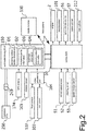
- Fig. 2 illustrates a control block diagram of the tractor 1.
- the tractor 1 includes a vehicle ECU 50 as a control unit controlling the travelling of the vehicle, and the automated driving ECU 150 processing position information according to the signal received by the GPS antenna 174, comparing the planned travel path P with its own position, and sending a control signal to the vehicle ECU 50.
- signals are input from a vehicle speed sensor 51 detecting the vehicle speed, a steering sensor 52 detecting the steering angle of the front wheels 2, and a speed change sensor 53 detecting the position of the speed change.
- Signals output from the vehicle ECU are a signal controlling the output of the engine 2, an operation signal of the steering motor 101 controlling the steering angle of the steering wheels 8, a speed changing signal of a speed change device 56, a braking signal sent to a brake cylinder 57 operating the brake to stop the traveling of the vehicle, and a lifting signal sent to the main cylinder 212 lifting up and down the implement 200.
- the automated driving ECU 150 and the vehicle ECU 50 send and receive information to and from each other via wire communication, and control the vehicle depending on its position. Also, the automated driving ECU 150 is connected to an implement ECU 250 by means of an implement communication connector 249, and sends and receives information to and from it.
- the memory area of the implement ECU 250 stores implement identification information, and by obtaining the implement identification information, the automated driving ECU 150 recognizes the attached implement.
- the vehicle ECU 50 sends and receives information to and from the mobile terminal 106 via wireless communication, and displays the vehicle state or work conditions on a display of the mobile terminal 106.
- the video taken by the front camera 102 and the rear camera 103 is input to the video processing unit 104 and processed, and if an obstacle is detected, information on the detected obstacle is input to the automated driving ECU 150.
- the obstacle sensor 105 detects obstacles by radiating a laser beam and receiving a reflected signal, and inputs an obstacle detection signal to the automated driving ECU 150.
- the automated driving ECU 150 has traveling vehicle profile information D1 and implement profile information D2, and invokes, from the implement profile information D2, profile data that corresponds to the implement identification information obtained from the implement ECU 250 and applies it to the traveling vehicle profile information D1 to use for traveling to avoid the obstacle.
- the automated driving ECU 150 also has farm field information D3 on the shape, position, etc. of the farm field, and obstacle position information D4 that preliminarily stores the positions of obstacles in the farm field.
- Fig. 3 illustrates a schematic perspective view of the front of the hood 5 of the tractor 1.
- the obstacle detection sensor 105 is disposed in the opening 5a provided in the front of the hood 5.
- the obstacle detection sensor 105 detects the existence of an object and may be an infrared sensor, an ultrasonic-wave sensor or a millimeter-wave radar, for example.
- the obstacle detection sensor 105 is attached to an upper sensor attachment stay 105a, four corners of which are attached to a lower sensor attachment stay 105b fixed to the hood 5, by bolts 105c and springs 105s as an example of a resilient member. Since the vibrations of the engine, etc. are absorbed by the four springs 105s, the vibrations have a reduced effect when the obstacle sensor 105 detects an obstacle.
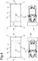
- Fig. 4 illustrates a pattern diagram of tractor profile information of different implements attached.
- the automated driving ECU 150 reads out the profile information of the implement 200r from the implement profile information D2 in plan view, and produces work vehicle profile information D5 that is profile information of the whole tractor 1 in plan view, corresponding to the rear of the traveling vehicle profile information D1 in plan view, for avoidance of obstacles.
- the implement profile information D2 includes position information of the vehicle body 100 with respect to the GPS antenna 174, and the implement profile information D2 is added to the traveling vehicle profile information D1 with the precise position, with a GPS antenna position G of the traveling vehicle profile information D1 as the reference point.
- the work vehicle profile information D5 is produced for the whole tractor 1 in which an implement is attached to the vehicle body 100.
- the work vehicle profile information D5 is represented by nine points of four corners C1 to C4 of a rectangle that covers the whole work vehicle (1) in plan view, four midpoints M1 to M4 therebetween, and the GPS antenna position G.
- the automated driving ECU 150 reads out the profile information of the implement 200f from the implement profile information D2, and produces the work vehicle profile information D5 corresponding to the front of the traveling vehicle profile information D1, for avoidance of obstacles.
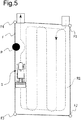
- Fig. 5 illustrates a pattern diagram of a planned travel path for autonomous traveling.
- a planned travel path R is set for the tractor 1 to the rear of which a cultivating machine is attached for example to travel back and forth in the farm field F, and go out of the farm field at the end through the inner circumference of the farm field.
- Outer circumference points F1 to F4 determine the position and the shape of the farm field F, and are stored in the automated driving ECU 150 as the farm field information D3 (see Fig. 2 ).
- the farm field information D3 includes the obstacle position information D4 of an obstacle P, and the planned travel path R1 is set as a tentative course to avoid the obstacle P.
- Fig. 6 illustrates a pattern diagram of obstacle detection.
- the obstacle detection sensor 105 emits electromagnetic waves for example, and detects objects at a height or a higher position by detecting the reflected waves. In this way, in the radiation range A1 of the electromagnetic waves except blind areas P1, E1, the shapes of objects P2, E2, E3 at a height or a higher position and their relative positions to the vehicle are detected, and recognized by the automated driving ECU 150.
- Fig. 7 illustrates a pattern diagram of avoidance traveling upon detection of an obstacle.
- the tractor 1 autonomously travels with the GPS antenna position G moving along the tentative planned travel path R1
- the vehicle is decelerated by speed change operation or controlling the engine speed, and if the obstacle P or a ridge surface E detected by the obstacle detection sensor 105 does not interfere with the predicted position of the work vehicle profile information D5 sometime later (e.g., 10 seconds later), the tractor 1 is allowed to autonomously travel without changing the planned travel path R1.
- the speed after the deceleration is preferably controlled with the average values, etc. of the vehicle speed or the engine speed within some time before the deceleration as the reference.
- the planned travel path R1 if the obstacle P or the ridge surface E detected by the obstacle detection sensor 105 interferes with the predicted position of the work vehicle profile information D5 sometime later (e.g., 10 seconds later), the planned travel path R1 is changed to an alternative travel path R2 by re-computing from the work vehicle profile information D5, to allow the tractor 1 to autonomously travel.
- the tractor 1 is stopped (point S).
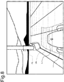
- Fig. 8 illustrates a pattern diagram of an example of video taken by the front camera.
- the obstacles P, E, U are detected by the obstacle detection sensor 105, but the present invention is not limited to that, and an obstacle P5 may be detected by analyzing the video image taken by the front camera 102, and then superimposing a predicted position D6 of the work vehicle profile information D5 sometime later (e.g., 10 seconds later) on the camera's video to determine whether the line of the predicted position D6 intersects with the detected obstacle P5.
- Fig. 9 illustrates a pattern diagram of an example of video taken by the rear camera.
- the implement profile of the implement 200 including its width is obtained from the implement profile information D2 stored in the automated driving ECU 150, but the present invention is not limited to that, and a width W or a length L to the rear end of the attached implement 200 may be obtained by analyzing the video image taken by the rear camera 103.
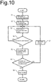
- Fig. 10 illustrates a flowchart of control of autonomous driving.
- the autonomous driving is started, the implement 200 attached before the start of the traveling is recognized by the automated driving ECU 150 (step S1).
- the automated driving ECU 150 produces the work vehicle profile information D5 from the traveling vehicle profile information D1 and the implement profile information D2 (step S2).
- a predicted position of the work vehicle profile information D5 sometime later is calculated for example from the traveling state including the speed, steering angle, etc. (step S3).
- the automated driving ECU 150 determines whether the obstacle (P, E, U) detected by the obstacle detection sensor 105 interferes with the calculated predicted position (step S4), and if there is no interference, the travelling while calculating predicted positions is continued (returns to step S3).
- the obstacle position information D4 preliminarily stored is referred with respect to the position of the obstacle (P, E, U) detected by the obstacle detection sensor 105 (step S5), and it is determined whether the obstacle position information D4 includes the obstacle (step S6). If it does, avoidance driving is carried out (step S7), and the autonomous driving is continued (returns to step S3). If the obstacle has not been stored, the traveling by autonomous driving is stopped (step S8).
- the tractor 1 recognizes the attached implement 200, and travels on a new travel path R2 by changing the travel path R1 corresponding to the implement 200, and therefore, even when the implements 200r, 200f of different shapes are attached, contact with the obstacles P, E is avoided in the autonomous traveling, and work is efficiently performed.
- the obstacles P, E are avoided while the machine recognizes the work vehicle profile information D5 of the attached implement 200 including the implement profile information D2, and therefore, even when the implements 200r, 200f of different shapes are attached, contact with the obstacles P, E is avoided in the autonomous traveling, and work is efficiently performed.
- the traveling is stopped at the point of time S when the contact is expected, to avoid contact with the obstacle U in the autonomous traveling.
- the tractor 1 of the configurations described here avoids contact with obstacles in the autonomous traveling, and work is efficiently performed.
- the invention comprises: a positioning device 174 measuring the vehicle body's own position; an obstacle recognition means 105 recognizing an obstacle P, E, U; and a control unit having the vehicle autonomously travel on a planned travel path R1 preliminarily set; wherein the control unit 150 includes obstacle position information D4 preliminarily stored; while traveling on the planned travel path R1, when an obstacle P, E is recognized by the obstacle recognition means 105, at a position stored in the obstacle position information D4, avoidance driving is performed to avoid contact with the obstacle P, E; and when the position of an obstacle U recognized by the obstacle recognition means 105 is different from the stored obstacle position information D4, the traveling is stopped.
Landscapes
- Engineering & Computer Science (AREA)
- Life Sciences & Earth Sciences (AREA)
- Aviation & Aerospace Engineering (AREA)
- Radar, Positioning & Navigation (AREA)
- Remote Sensing (AREA)
- Physics & Mathematics (AREA)
- General Physics & Mathematics (AREA)
- Automation & Control Theory (AREA)
- Mechanical Engineering (AREA)
- Soil Sciences (AREA)
- Environmental Sciences (AREA)
- Guiding Agricultural Machines (AREA)
- Business, Economics & Management (AREA)
- Health & Medical Sciences (AREA)
- Artificial Intelligence (AREA)
- Evolutionary Computation (AREA)
- Game Theory and Decision Science (AREA)
- Medical Informatics (AREA)
- Control Of Position, Course, Altitude, Or Attitude Of Moving Bodies (AREA)
Description
- The present invention relates to a work vehicle performing work in the farm field while traveling therein.
- There is known art (e.g., Patent Document 1) with which a work vehicle includes a cultivating machine attached to the rear of the vehicle body, and performs work while traveling in the farm field, and the work vehicle further includes a front camera checking the conditions of the road surface in the front, and an ultrasonic-wave sensor detecting the distance to an obstacle in the front. If the distance to the obstacle calculated by image recognition of the camera is substantially the same as that detected by the ultrasonic-wave sensor, a turning position is set before the detected obstacle, and the operator is notified when the work vehicle has reached the turning position, and when the turning is started, the rear wheel on the inside side of the turn is automatically braked, while the implement is automatically lifted up.
- [Patent Document 1]
Japanese Unexamined Patent Application Publication No. 2011-62115 US 2017/010619 A1 disclosing an automation kit for an agricultural vehicle, inWO 2017/026080 A1 which addresses a route designing method for autonomous vehicle or inEP 3 104 244 A1 - The above technology, however, is only to notify the timing for turning upon detection of an obstacle, but not to avoid it. If there is a preliminarily known obstacle, avoiding it by avoidance driving to continue work may allow for efficient work. An object of the present invention is to provide a work vehicle allowing for safe work, while avoiding expected obstacles.
- To achieve the above object, the present invention has the following features.
- A first feature of the invention comprises: a positioning device (174) measuring the vehicle body's own position by receiving positional signals (31) sent from a plurality of satellites (30); an obstacle detection sensor (105) recognizing an obstacle (P, E, U); and a control unit (150) having the vehicle autonomously travel by controlling steering on a planned travel path (R1) preliminarily set; wherein the control unit (150) includes obstacle position information (D4) preliminarily stored; while traveling on the planned travel path (R1), when an obstacle (P, E, U) is detected by the obstacle detection sensor (105), , avoidance driving is performed to avoid contact with the obstacle (P, E) and the autonomously travel is continued, when a position of the detected obstacle (P,E) is found in the obstacle position information (D4); and when the position of an obstacle (U) detected by the obstacle detection sensor (105) is not found in the obstacle position information (D4), the traveling is stopped.
- As a result, work is efficiently performed while the preliminarily expected obstacles (P, E) are avoided, and for the obstacle (U) that is not preliminarily expected, in consideration of unexpected contingency, the traveling is stopped to avoid contact with the obstacle (U) in the autonomous traveling for safe work.
- A second feature of the invention is the work vehicle (1) of the first feature wherein the control unit (150) includes: travelling vehicle profile information (D1), and implement profile information (D2) of the attached implement (200); the travelling vehicle profile information (D1) and the implement profile information (D2) include position information of the positioning device (174); with respect to the position (G) of the positioning device (174), work vehicle profile information (D5) is calculated by adding the implement profile information (D2) to the travelling vehicle profile information (D1); and according to the work vehicle profile information (D5), an avoidance path is set to avoid contact with the obstacle (P, E, U).
- As a result, the work vehicle profile information (D5) that is the own shape including the profile information (D2) of the attached implement (200) is recognized, and therefore, even when the implements (200r, 200f) of different shapes are attached, contact with the obstacles (P, E) is avoided in the autonomous traveling, and work is efficiently and safely performed.
- A third feature of the invention is the work vehicle (1) of the second feature wherein the control unit (150) calculates a predicted position of the work vehicle profile information (D5) of when the work vehicle (1) autonomously travels in such a way that the position (G) of the positioning device (174) moves along the planned travel path (R1) preliminarily set; and when the predicted position interferes with the recognized obstacle (P, E), changes the planned travel path (R1), and sets an alternative travel path (R2) in which the predicted position does not interfere with the work vehicle profile information (D5).
- When the different implements (200r, 200f) are attached to the tractor (1), when running on the same travel trajectory (R1), the vehicle recognizes the work vehicle profile information (D5), and if contact with the obstacle (P, E) is predicted, travels on a new travel path (R2) by changing the travel path (R1) corresponding to the implement (200) attached, and therefore, even when the implements (200r, 200f) of different shapes are attached, contact with the obstacles (P, E) is avoided in the autonomous traveling, and work is efficiently and safely performed.
- According to the work vehicle (1) of the above features of the invention, contact with obstacles (P, E, U) in the autonomous traveling is avoided, and work is efficiently and safely performed.
-
- [
Fig. 1] Fig. 1 illustrates a side view of a tractor of the present embodiment. - [
Fig. 2] Fig. 2 illustrates a control block diagram. - [
Fig. 3] Fig. 3 illustrates schematic perspective view of the front of a hood. - [
Fig. 4] Fig. 4 illustrates a pattern diagram of tractor profile information with a different implement attached. - [
Fig. 5] Fig. 5 illustrates a pattern diagram of a planned travel path for autonomous traveling. - [
Fig. 6] Fig. 6 illustrates a pattern diagram of obstacle detection. - [
Fig. 7] Fig. 7 illustrates a pattern diagram of avoidance traveling upon obstacle detection. - [
Fig. 8] Fig. 8 illustrates a pattern diagram of an example of video taken by a front camera. - [
Fig. 9] Fig. 9 illustrates a pattern diagram of an example of video taken by a rear camera. - [
Fig. 10] Fig. 10 illustrates a flowchart of control of autonomous driving. - Now, embodiments of a work vehicle of the present invention will be explained with reference to the drawings.
-
Fig. 1 illustrates an allover side view of atractor 1 as an example a work vehicle of the present invention, and thetractor 1 comprises: avehicle body 100; animplement 200 attached to thevehicle body 100; ahood 5 provided in the front of thetractor 1, anengine 2 disposed in thehood 5; afront axle 4; arear axle 5;front wheels 6;rear wheels 7; atransmission case 3 appropriately changing the speed of the force of theengine 2 and then transmitting to thefront axle 4 and therear axle 5 to drive thefront wheels 6 and therear wheels 7 or only therear wheels 7; acabin 26 provided on the machine; aseat 10 provided in thecabin 26; and asteering wheel 8, vertically disposed in the center of thecabin 26, for the operator to operate to steer thefront wheels 6 for traveling. Theimplement 200 such as a rotary tiller is attached to a lower link 9 projecting from the rear of the machine, and aPTO shaft 11 that projects rearward from thetransmission case 3 drives the attachedimplement 200. - The rear of the
implement 200 is covered by arear cover 201, which rotates about a rear-cover rotatingshaft 201a provided in the right-left direction of the vehicle. In cultivating work, abottom end 201b of therear cover 201 makes contact with the ground surface and levels the soil after it is cultivated. - The
implement 200 is supported at three points by the right and left lower links 9 and atop link 213, and the left lower link 9L is connected by aleft lift arm 210L and aninclinable cylinder 214 that is a type of an actuator. The lift arm 210 is rotated up and down by means of amain cylinder 212, and the up-down rotation of the lift arm 210 lifts up and down theimplement 200. The rotation angle of the lift arm 210 is detected by alift arm sensor 211. - On an upper surface of a
cabin roof 27, a global positioning system (GPS)antenna 174 as an example of a positioning device is provided, and theGPS antenna 174 receives apositioning signal 31 sent from a plurality ofGPS satellites 30 and measures its own position. TheGPS antenna 174 is attached to thecabin roof 27 by aGPS antenna stay 173 including ahorizontal support member 173a mainly formed of a bendable round bar material provided from right to left of thecabin roof 27, and anantenna fixing member 173b mainly formed of a bendable steel plate material. - A
front camera 102 as an example of a first camera taking video of the front of thetractor 1 is attached to a front camera stay 102a in such a manner that it rotates up and down, and the front camera stay 102a is attached to the lower surface of theantenna fixing member 173b of the GPS antenna stay 173 that clamps the front center of thecabin roof 27 from the top and bottom. Arear camera 103 as an example of a second camera taking video of the rear of thetractor 1 is attached to a plate-like rear camera stay 103a, in such a manner that it rotates up and down, and the rear camera stay 103a is attached to the lower surface of thecabin roof 27 in the rear center of thecabin roof 27. - A
video processing unit 104 processing the video of thefront camera 103 and therear camera 104 is attached to the rear of the operator'sseat 10 in thecabin 26. Anobstacle sensor 105 is provided in an opening 5a provided in the front of thehood 5, and radiates electromagnetic waves or ultrasonic waves toward the front to detect whether there is an obstacle in front of thetractor 1, and if there is, the distance to the obstacle. - Next to the
steering wheel 8, amobile terminal 106 such as a tablet terminal to manage work and set up the vehicle is provided. Themobile terminal 106 is also used as input means to input parameters when setting up a planned travel path P for automated driving. - A steering shaft (not illustrated) is provided below the
steering wheel 8, and asteering motor 101 electronically controlling the steering is provided next to the steering shaft. - In the
hood 5, an automated driving electronic control unit (ECU) 150 as an example of a control unit is provided, and theautomated driving ECU 150 controls theengine 2 and thesteering wheel 8 so that the machine travels along the planned travel path P, by comparing the planned travel path P with its own position calculated according to thepositioning signal 31 received by theGPS antenna 174. -
Fig. 2 illustrates a control block diagram of thetractor 1. Thetractor 1 includes avehicle ECU 50 as a control unit controlling the travelling of the vehicle, and theautomated driving ECU 150 processing position information according to the signal received by theGPS antenna 174, comparing the planned travel path P with its own position, and sending a control signal to thevehicle ECU 50. - To the vehicle ECU, signals are input from a
vehicle speed sensor 51 detecting the vehicle speed, asteering sensor 52 detecting the steering angle of thefront wheels 2, and aspeed change sensor 53 detecting the position of the speed change. Signals output from the vehicle ECU are a signal controlling the output of theengine 2, an operation signal of thesteering motor 101 controlling the steering angle of thesteering wheels 8, a speed changing signal of aspeed change device 56, a braking signal sent to abrake cylinder 57 operating the brake to stop the traveling of the vehicle, and a lifting signal sent to themain cylinder 212 lifting up and down theimplement 200. - The automated driving ECU 150 and the vehicle ECU 50 send and receive information to and from each other via wire communication, and control the vehicle depending on its position. Also, the automated driving ECU 150 is connected to an implement ECU 250 by means of an
implement communication connector 249, and sends and receives information to and from it. The memory area of the implement ECU 250 stores implement identification information, and by obtaining the implement identification information, the automated driving ECU 150 recognizes the attached implement. The vehicle ECU 50 sends and receives information to and from themobile terminal 106 via wireless communication, and displays the vehicle state or work conditions on a display of themobile terminal 106. - The video taken by the
front camera 102 and therear camera 103 is input to thevideo processing unit 104 and processed, and if an obstacle is detected, information on the detected obstacle is input to theautomated driving ECU 150. Theobstacle sensor 105 detects obstacles by radiating a laser beam and receiving a reflected signal, and inputs an obstacle detection signal to theautomated driving ECU 150. - The automated driving ECU 150 has traveling vehicle profile information D1 and implement profile information D2, and invokes, from the implement profile information D2, profile data that corresponds to the implement identification information obtained from the
implement ECU 250 and applies it to the traveling vehicle profile information D1 to use for traveling to avoid the obstacle. The automated driving ECU 150 also has farm field information D3 on the shape, position, etc. of the farm field, and obstacle position information D4 that preliminarily stores the positions of obstacles in the farm field. -
Fig. 3 illustrates a schematic perspective view of the front of thehood 5 of thetractor 1. Theobstacle detection sensor 105 is disposed in theopening 5a provided in the front of thehood 5. Theobstacle detection sensor 105 detects the existence of an object and may be an infrared sensor, an ultrasonic-wave sensor or a millimeter-wave radar, for example. Theobstacle detection sensor 105 is attached to an uppersensor attachment stay 105a, four corners of which are attached to a lowersensor attachment stay 105b fixed to thehood 5, bybolts 105c andsprings 105s as an example of a resilient member. Since the vibrations of the engine, etc. are absorbed by the foursprings 105s, the vibrations have a reduced effect when theobstacle sensor 105 detects an obstacle. -
Fig. 4 illustrates a pattern diagram of tractor profile information of different implements attached. When an implement 200r is attached to the rear, the automated drivingECU 150 reads out the profile information of the implement 200r from the implement profile information D2 in plan view, and produces work vehicle profile information D5 that is profile information of thewhole tractor 1 in plan view, corresponding to the rear of the traveling vehicle profile information D1 in plan view, for avoidance of obstacles. - The implement profile information D2 includes position information of the
vehicle body 100 with respect to theGPS antenna 174, and the implement profile information D2 is added to the traveling vehicle profile information D1 with the precise position, with a GPS antenna position G of the traveling vehicle profile information D1 as the reference point. As a result, the work vehicle profile information D5 is produced for thewhole tractor 1 in which an implement is attached to thevehicle body 100. At this time, the work vehicle profile information D5 is represented by nine points of four corners C1 to C4 of a rectangle that covers the whole work vehicle (1) in plan view, four midpoints M1 to M4 therebetween, and the GPS antenna position G. - When an implement 200f is attached to the front of the vehicle, the automated driving
ECU 150 reads out the profile information of the implement 200f from the implement profile information D2, and produces the work vehicle profile information D5 corresponding to the front of the traveling vehicle profile information D1, for avoidance of obstacles. -
Fig. 5 illustrates a pattern diagram of a planned travel path for autonomous traveling. Here, a planned travel path R is set for thetractor 1 to the rear of which a cultivating machine is attached for example to travel back and forth in the farm field F, and go out of the farm field at the end through the inner circumference of the farm field. Outer circumference points F1 to F4 determine the position and the shape of the farm field F, and are stored in the automated drivingECU 150 as the farm field information D3 (seeFig. 2 ). The farm field information D3 includes the obstacle position information D4 of an obstacle P, and the planned travel path R1 is set as a tentative course to avoid the obstacle P. -
Fig. 6 illustrates a pattern diagram of obstacle detection. Theobstacle detection sensor 105 emits electromagnetic waves for example, and detects objects at a height or a higher position by detecting the reflected waves. In this way, in the radiation range A1 of the electromagnetic waves except blind areas P1, E1, the shapes of objects P2, E2, E3 at a height or a higher position and their relative positions to the vehicle are detected, and recognized by the automated drivingECU 150. -
Fig. 7 illustrates a pattern diagram of avoidance traveling upon detection of an obstacle. When thetractor 1 autonomously travels with the GPS antenna position G moving along the tentative planned travel path R1, if thetractor 1 approaches a position stored in the obstacle position information D4, the vehicle is decelerated by speed change operation or controlling the engine speed, and if the obstacle P or a ridge surface E detected by theobstacle detection sensor 105 does not interfere with the predicted position of the work vehicle profile information D5 sometime later (e.g., 10 seconds later), thetractor 1 is allowed to autonomously travel without changing the planned travel path R1. When reducing the speed as described here, the speed after the deceleration is preferably controlled with the average values, etc. of the vehicle speed or the engine speed within some time before the deceleration as the reference. - In the tentative planned travel path R1, if the obstacle P or the ridge surface E detected by the
obstacle detection sensor 105 interferes with the predicted position of the work vehicle profile information D5 sometime later (e.g., 10 seconds later), the planned travel path R1 is changed to an alternative travel path R2 by re-computing from the work vehicle profile information D5, to allow thetractor 1 to autonomously travel. - If the
obstacle detection sensor 105 has detected an obstacle U that is not preliminarily set in the planned travel path R1, and if the predicted position of the work vehicle profile information D5 sometime later (e.g., 10 seconds later) interferes with it, thetractor 1 is stopped (point S). -
Fig. 8 illustrates a pattern diagram of an example of video taken by the front camera. In the above embodiment, the obstacles P, E, U are detected by theobstacle detection sensor 105, but the present invention is not limited to that, and an obstacle P5 may be detected by analyzing the video image taken by thefront camera 102, and then superimposing a predicted position D6 of the work vehicle profile information D5 sometime later (e.g., 10 seconds later) on the camera's video to determine whether the line of the predicted position D6 intersects with the detected obstacle P5. -
Fig. 9 illustrates a pattern diagram of an example of video taken by the rear camera. In the above embodiment, the implement profile of the implement 200 including its width is obtained from the implement profile information D2 stored in the automated drivingECU 150, but the present invention is not limited to that, and a width W or a length L to the rear end of the attached implement 200 may be obtained by analyzing the video image taken by therear camera 103. -
Fig. 10 illustrates a flowchart of control of autonomous driving. When the autonomous driving is started, the implement 200 attached before the start of the traveling is recognized by the automated driving ECU 150 (step S1). Upon recognition of the implement 200, the automated drivingECU 150 produces the work vehicle profile information D5 from the traveling vehicle profile information D1 and the implement profile information D2 (step S2). - According to the produced work vehicle profile information D5, a predicted position of the work vehicle profile information D5 sometime later is calculated for example from the traveling state including the speed, steering angle, etc. (step S3). The automated driving
ECU 150 determines whether the obstacle (P, E, U) detected by theobstacle detection sensor 105 interferes with the calculated predicted position (step S4), and if there is no interference, the travelling while calculating predicted positions is continued (returns to step S3). - If interference with the obstacle is predicted, the obstacle position information D4 preliminarily stored is referred with respect to the position of the obstacle (P, E, U) detected by the obstacle detection sensor 105 (step S5), and it is determined whether the obstacle position information D4 includes the obstacle (step S6). If it does, avoidance driving is carried out (step S7), and the autonomous driving is continued (returns to step S3). If the obstacle has not been stored, the traveling by autonomous driving is stopped (step S8).
- With the configurations described here, even when the
different implements tractor 1, when running on the same travel trajectory R1, thetractor 1 recognizes the attached implement 200, and travels on a new travel path R2 by changing the travel path R1 corresponding to the implement 200, and therefore, even when theimplements - Also, the obstacles P, E are avoided while the machine recognizes the work vehicle profile information D5 of the attached implement 200 including the implement profile information D2, and therefore, even when the
implements - For the obstacle U that is not preliminarily expected, in consideration of unexpected contingency, the traveling is stopped at the point of time S when the contact is expected, to avoid contact with the obstacle U in the autonomous traveling.
- Also, since the work vehicle profile information D5 is precisely calculated, even when the
implements - The
tractor 1 of the configurations described here avoids contact with obstacles in the autonomous traveling, and work is efficiently performed. -
- 1
- tractor (work vehicle)
- 100
- vehicle body
- 105
- obstacle detection sensor (implement recognition means)
- 150
- automated driving ECU (control unit)
- 174
- GPS antenna (positioning device)
- 200
- implement
- D1
- travelling vehicle profile information
- D2
- implement profile information
- D4
- obstacle position information
- D5
- work vehicle profile information
- R1
- planned travel path
- E
- obstacle
- G
- position of GPS antenna (positioning device)
- P
- obstacle
- U
- obstacle
- [Object] To provide a work vehicle in the autonomous traveling of which contact with obstacles is avoided, and work is efficiently and safely performed.
- [Solution] The invention comprises: a
positioning device 174 measuring the vehicle body's own position; an obstacle recognition means 105 recognizing an obstacle P, E, U; and a control unit having the vehicle autonomously travel on a planned travel path R1 preliminarily set; wherein thecontrol unit 150 includes obstacle position information D4 preliminarily stored; while traveling on the planned travel path R1, when an obstacle P, E is recognized by the obstacle recognition means 105, at a position stored in the obstacle position information D4, avoidance driving is performed to avoid contact with the obstacle P, E; and when the position of an obstacle U recognized by the obstacle recognition means 105 is different from the stored obstacle position information D4, the traveling is stopped.
Claims (3)
- A work vehicle comprising:a positioning device (174) for measuring the vehicle body's own position by receiving positional signals (31) sent from a plurality of satellites (30);an obstacle detection sensor (105) for detecting an obstacle (P, E, U); anda control unit (150) configured to have the vehicle autonomously travel by controlling steering on a planned travel path (R1) preliminarily set; whereinthe control unit (150) includes obstacle position information (D4) preliminarily stored;while traveling on the planned travel path (R1), when an obstacle (P, E, U) is detected by the obstacle detection sensor (105), ,the control unit is configured to perform avoidance driving to avoid contact with an obstacle (P, E) and the autonomously travel is continued, when a position of the detected obstacle (P,E) is found in the obstacle position information (D4); characterized in thatthe control unit is configured to stop the travelling when the position of an obstacle (U) detected by the obstacle detection sensor (105) is not found in the obstacle position information (D4).
- The work vehicle of claim 1 wherein
the control unit (150) includes:travelling vehicle profile information (D1), and implement profile information (D2) of the attached implement (200);the travelling vehicle profile information (D1) and the implement profile information (D2) include position information of the positioning device (174);with respect to the position (G) of the positioning device (174), work vehicle profile information (D5) is calculated by adding the implement profile information (D2) to the travelling vehicle profile information (D1); andaccording to the work vehicle profile information (D5), an avoidance path is set to avoid contact with the obstacle (P, E, U). - The work vehicle of claim 2 whereinthe control unit (150) calculates a predicted position of the work vehicle profile information (D5) of when the work vehicle (1) autonomously travels in such a way that the position (G) of the positioning device (174) moves along the planned travel path (R1) preliminarily set; andwhen the predicted position interferes with the detected obstacle (P, E), changes the planned travel path (R1), and sets an alternative travel path (R2) in which the predicted position does not interfere with the work vehicle profile information (D5).
Applications Claiming Priority (1)
| Application Number | Priority Date | Filing Date | Title |
|---|---|---|---|
| JP2017230750A JP6919531B2 (en) | 2017-11-30 | 2017-11-30 | Work vehicle |
Publications (2)
| Publication Number | Publication Date |
|---|---|
| EP3491904A1 EP3491904A1 (en) | 2019-06-05 |
| EP3491904B1 true EP3491904B1 (en) | 2022-01-05 |
Family
ID=64559519
Family Applications (1)
| Application Number | Title | Priority Date | Filing Date |
|---|---|---|---|
| EP18209120.7A Active EP3491904B1 (en) | 2017-11-30 | 2018-11-29 | Agricultural work vehicle |
Country Status (5)
| Country | Link |
|---|---|
| US (1) | US10564642B2 (en) |
| EP (1) | EP3491904B1 (en) |
| JP (1) | JP6919531B2 (en) |
| CN (1) | CN109857096B (en) |
| MY (1) | MY189233A (en) |
Cited By (1)
| Publication number | Priority date | Publication date | Assignee | Title |
|---|---|---|---|---|
| US20220210971A1 (en) * | 2019-04-25 | 2022-07-07 | Kubota Corporation | Agricultural Work Machine Such as Harvester |
Families Citing this family (26)
| Publication number | Priority date | Publication date | Assignee | Title |
|---|---|---|---|---|
| JP6863358B2 (en) * | 2018-10-26 | 2021-04-21 | 井関農機株式会社 | Work vehicle |
| JP7565677B2 (en) * | 2019-06-27 | 2024-10-11 | 株式会社クボタ | Obstacle detection system for agricultural vehicles |
| JP7242446B2 (en) * | 2019-06-28 | 2023-03-20 | 株式会社クボタ | work support system, work vehicle |
| JP7247041B2 (en) * | 2019-07-08 | 2023-03-28 | 株式会社アクティオ | Sensor mounting stay for heavy machinery and heavy machinery with contact prevention function |
| JP7232417B2 (en) * | 2019-08-30 | 2023-03-03 | 井関農機株式会社 | work vehicle |
| JP7657542B2 (en) * | 2019-10-18 | 2025-04-07 | ヤンマーパワーテクノロジー株式会社 | Obstacle Detection System |
| US11212953B2 (en) * | 2019-10-31 | 2022-01-04 | Deere & Company | Vehicle attachment carrier loading guidance |
| JP7407569B2 (en) * | 2019-11-26 | 2024-01-04 | ヤンマーパワーテクノロジー株式会社 | Area registration system |
| JP7258737B2 (en) * | 2019-12-18 | 2023-04-17 | 株式会社クボタ | work vehicle |
| JP7271416B2 (en) * | 2019-12-27 | 2023-05-11 | 株式会社クボタ | Work vehicle and travel management system for work vehicle |
| JP7301737B2 (en) * | 2019-12-27 | 2023-07-03 | 株式会社クボタ | work vehicle |
| CN111679267B (en) * | 2020-08-17 | 2020-12-18 | 陕西耕辰科技有限公司 | Automatic driving system and obstacle detection system thereof |
| JP7555250B2 (en) | 2020-12-02 | 2024-09-24 | ヤンマーホールディングス株式会社 | Combine harvester and automatic operation method |
| JP7485591B2 (en) * | 2020-12-02 | 2024-05-16 | ヤンマーホールディングス株式会社 | Autonomous driving system, automatic driving method, and automatic driving program |
| JP7472005B2 (en) * | 2020-12-02 | 2024-04-22 | ヤンマーホールディングス株式会社 | Autonomous driving system, automatic driving method, and automatic driving program |
| JP7515437B2 (en) * | 2021-04-14 | 2024-07-12 | 株式会社クボタ | Driving Management System |
| JP7515436B2 (en) * | 2021-04-14 | 2024-07-12 | 株式会社クボタ | Route Generation System |
| EP4407103A4 (en) * | 2021-09-24 | 2025-08-13 | Hitachi Construction Mach Co | CONTROL SYSTEM FOR WORKING MACHINE AND WORKING MACHINE |
| JP2023127875A (en) * | 2022-03-02 | 2023-09-14 | ヤンマーホールディングス株式会社 | Automatic driving method, automatic driving system, and automatic driving program |
| JP7826817B2 (en) * | 2022-04-08 | 2026-03-10 | 株式会社豊田自動織機 | Obstacle detection device and driving control device |
| KR102458856B1 (en) * | 2022-04-20 | 2022-10-26 | 주식회사 긴트 | Method and apparatus for predicting potential accidents and controlling actions to avoid potential accidents for agricultural machinery performing autonomous driving and operating a pto in a communication system |
| EP4541163A4 (en) * | 2022-06-21 | 2025-10-01 | Kubota Kk | DRIVING CONTROL SYSTEM, AGRICULTURAL MACHINE AND DRIVING CONTROL METHOD |
| WO2024004486A1 (en) * | 2022-06-29 | 2024-01-04 | 株式会社クボタ | Work vehicle, control method, and control system |
| US20240147888A1 (en) * | 2022-11-07 | 2024-05-09 | Trimble Inc. | Autonomous vehicle boundary intersection detection and avoidance |
| JP2024116593A (en) * | 2023-02-16 | 2024-08-28 | ヤンマーホールディングス株式会社 | Automatic steering method, automatic steering system, and automatic steering program |
| JP2024179715A (en) * | 2023-06-15 | 2024-12-26 | 井関農機株式会社 | Work vehicles |
Family Cites Families (12)
| Publication number | Priority date | Publication date | Assignee | Title |
|---|---|---|---|---|
| US6934615B2 (en) * | 2003-03-31 | 2005-08-23 | Deere & Company | Method and system for determining an efficient vehicle path |
| JP2011062115A (en) | 2009-09-16 | 2011-03-31 | Iseki & Co Ltd | Working vehicle |
| KR20250174095A (en) * | 2014-02-06 | 2025-12-11 | 얀마 파워 테크놀로지 가부시키가이샤 | Parallel travel work system |
| EP3171241A4 (en) * | 2014-07-16 | 2017-12-13 | Ricoh Company, Ltd. | System, machine, control method, and program |
| KR102192966B1 (en) * | 2014-11-13 | 2020-12-18 | 얀마 파워 테크놀로지 가부시키가이샤 | Operation terminal |
| US20170010619A1 (en) * | 2015-07-08 | 2017-01-12 | Cnh Industrial America Llc | Automation kit for an agricultural vehicle |
| WO2017026080A1 (en) * | 2015-08-13 | 2017-02-16 | ヤンマー株式会社 | Route designing method for autonomous vehicle |
| CN105654808A (en) * | 2016-02-03 | 2016-06-08 | 北京易驾佳信息科技有限公司 | Intelligent training system for vehicle driver based on actual vehicle |
| KR102283928B1 (en) * | 2016-05-10 | 2021-07-29 | 얀마 파워 테크놀로지 가부시키가이샤 | Autonomous travel route generating system |
| JP6701002B2 (en) * | 2016-06-23 | 2020-05-27 | 株式会社クボタ | Driving support system and work vehicle |
| CN106985815B (en) * | 2017-03-14 | 2019-05-03 | 重庆长安汽车股份有限公司 | It is remotely controlled parking system and method |
| JP6880914B2 (en) * | 2017-03-28 | 2021-06-02 | 井関農機株式会社 | Work vehicle and automatic stop system for work vehicle |
-
2017
- 2017-11-30 JP JP2017230750A patent/JP6919531B2/en active Active
-
2018
- 2018-11-27 MY MYPI2018002136A patent/MY189233A/en unknown
- 2018-11-29 EP EP18209120.7A patent/EP3491904B1/en active Active
- 2018-11-30 CN CN201811460163.2A patent/CN109857096B/en active Active
- 2018-11-30 US US16/205,621 patent/US10564642B2/en not_active Expired - Fee Related
Non-Patent Citations (1)
| Title |
|---|
| None * |
Cited By (2)
| Publication number | Priority date | Publication date | Assignee | Title |
|---|---|---|---|---|
| US20220210971A1 (en) * | 2019-04-25 | 2022-07-07 | Kubota Corporation | Agricultural Work Machine Such as Harvester |
| US12245548B2 (en) * | 2019-04-25 | 2025-03-11 | Kubota Corporation | Agricultural work machine such as harvester |
Also Published As
| Publication number | Publication date |
|---|---|
| CN109857096A (en) | 2019-06-07 |
| US20190163190A1 (en) | 2019-05-30 |
| US10564642B2 (en) | 2020-02-18 |
| JP2019097454A (en) | 2019-06-24 |
| MY189233A (en) | 2022-01-31 |
| EP3491904A1 (en) | 2019-06-05 |
| CN109857096B (en) | 2024-10-29 |
| JP6919531B2 (en) | 2021-08-18 |
Similar Documents
| Publication | Publication Date | Title |
|---|---|---|
| EP3491904A1 (en) | Work vehicle | |
| EP3998516B1 (en) | Automatic travel system | |
| JP7044694B2 (en) | Obstacle detection system for work vehicles | |
| JP7349277B2 (en) | Automated driving system for work vehicles | |
| US20210018617A1 (en) | Obstacle Detection System for Work Vehicle | |
| CN111373894B (en) | Work vehicle | |
| WO2020137134A1 (en) | Collision avoidance system for work vehicle | |
| CN107544488A (en) | Travel assist system and Operation Van | |
| JP6781055B2 (en) | Work vehicle | |
| WO2021010297A1 (en) | Automatic traveling system | |
| JP7317165B2 (en) | Obstacle detection system for work vehicles | |
| WO2020044805A1 (en) | Work vehicle autonomous travel system | |
| JP7827779B2 (en) | Tractor | |
| JP6781056B2 (en) | Work vehicle | |
| CN113835426A (en) | work vehicle system | |
| JP3582694B2 (en) | Traveling work vehicle | |
| JP2024083721A (en) | Automatic control device for farm work vehicles | |
| JP2025134485A (en) | Work vehicle route generation system | |
| JP2026065526A (en) | Work vehicles | |
| JP2021013381A (en) | Working vehicle | |
| JP2018114926A (en) | Service car |
Legal Events
| Date | Code | Title | Description |
|---|---|---|---|
| PUAI | Public reference made under article 153(3) epc to a published international application that has entered the european phase |
Free format text: ORIGINAL CODE: 0009012 |
|
| STAA | Information on the status of an ep patent application or granted ep patent |
Free format text: STATUS: THE APPLICATION HAS BEEN PUBLISHED |
|
| AK | Designated contracting states |
Kind code of ref document: A1 Designated state(s): AL AT BE BG CH CY CZ DE DK EE ES FI FR GB GR HR HU IE IS IT LI LT LU LV MC MK MT NL NO PL PT RO RS SE SI SK SM TR |
|
| AX | Request for extension of the european patent |
Extension state: BA ME |
|
| STAA | Information on the status of an ep patent application or granted ep patent |
Free format text: STATUS: REQUEST FOR EXAMINATION WAS MADE |
|
| 17P | Request for examination filed |
Effective date: 20191205 |
|
| RBV | Designated contracting states (corrected) |
Designated state(s): AL AT BE BG CH CY CZ DE DK EE ES FI FR GB GR HR HU IE IS IT LI LT LU LV MC MK MT NL NO PL PT RO RS SE SI SK SM TR |
|
| STAA | Information on the status of an ep patent application or granted ep patent |
Free format text: STATUS: EXAMINATION IS IN PROGRESS |
|
| 17Q | First examination report despatched |
Effective date: 20201105 |
|
| GRAP | Despatch of communication of intention to grant a patent |
Free format text: ORIGINAL CODE: EPIDOSNIGR1 |
|
| STAA | Information on the status of an ep patent application or granted ep patent |
Free format text: STATUS: GRANT OF PATENT IS INTENDED |
|
| INTG | Intention to grant announced |
Effective date: 20210625 |
|
| GRAS | Grant fee paid |
Free format text: ORIGINAL CODE: EPIDOSNIGR3 |
|
| GRAA | (expected) grant |
Free format text: ORIGINAL CODE: 0009210 |
|
| STAA | Information on the status of an ep patent application or granted ep patent |
Free format text: STATUS: THE PATENT HAS BEEN GRANTED |
|
| AK | Designated contracting states |
Kind code of ref document: B1 Designated state(s): AL AT BE BG CH CY CZ DE DK EE ES FI FR GB GR HR HU IE IS IT LI LT LU LV MC MK MT NL NO PL PT RO RS SE SI SK SM TR |
|
| REG | Reference to a national code |
Ref country code: GB Ref legal event code: FG4D |
|
| REG | Reference to a national code |
Ref country code: CH Ref legal event code: EP |
|
| REG | Reference to a national code |
Ref country code: AT Ref legal event code: REF Ref document number: 1459689 Country of ref document: AT Kind code of ref document: T Effective date: 20220115 |
|
| REG | Reference to a national code |
Ref country code: DE Ref legal event code: R096 Ref document number: 602018029070 Country of ref document: DE |
|
| REG | Reference to a national code |
Ref country code: IE Ref legal event code: FG4D |
|
| REG | Reference to a national code |
Ref country code: LT Ref legal event code: MG9D |
|
| REG | Reference to a national code |
Ref country code: NL Ref legal event code: MP Effective date: 20220105 |
|
| REG | Reference to a national code |
Ref country code: AT Ref legal event code: MK05 Ref document number: 1459689 Country of ref document: AT Kind code of ref document: T Effective date: 20220105 |
|
| PG25 | Lapsed in a contracting state [announced via postgrant information from national office to epo] |
Ref country code: NL Free format text: LAPSE BECAUSE OF FAILURE TO SUBMIT A TRANSLATION OF THE DESCRIPTION OR TO PAY THE FEE WITHIN THE PRESCRIBED TIME-LIMIT Effective date: 20220105 |
|
| PG25 | Lapsed in a contracting state [announced via postgrant information from national office to epo] |
Ref country code: SE Free format text: LAPSE BECAUSE OF FAILURE TO SUBMIT A TRANSLATION OF THE DESCRIPTION OR TO PAY THE FEE WITHIN THE PRESCRIBED TIME-LIMIT Effective date: 20220105 Ref country code: RS Free format text: LAPSE BECAUSE OF FAILURE TO SUBMIT A TRANSLATION OF THE DESCRIPTION OR TO PAY THE FEE WITHIN THE PRESCRIBED TIME-LIMIT Effective date: 20220105 Ref country code: PT Free format text: LAPSE BECAUSE OF FAILURE TO SUBMIT A TRANSLATION OF THE DESCRIPTION OR TO PAY THE FEE WITHIN THE PRESCRIBED TIME-LIMIT Effective date: 20220505 Ref country code: NO Free format text: LAPSE BECAUSE OF FAILURE TO SUBMIT A TRANSLATION OF THE DESCRIPTION OR TO PAY THE FEE WITHIN THE PRESCRIBED TIME-LIMIT Effective date: 20220405 Ref country code: LT Free format text: LAPSE BECAUSE OF FAILURE TO SUBMIT A TRANSLATION OF THE DESCRIPTION OR TO PAY THE FEE WITHIN THE PRESCRIBED TIME-LIMIT Effective date: 20220105 Ref country code: HR Free format text: LAPSE BECAUSE OF FAILURE TO SUBMIT A TRANSLATION OF THE DESCRIPTION OR TO PAY THE FEE WITHIN THE PRESCRIBED TIME-LIMIT Effective date: 20220105 Ref country code: ES Free format text: LAPSE BECAUSE OF FAILURE TO SUBMIT A TRANSLATION OF THE DESCRIPTION OR TO PAY THE FEE WITHIN THE PRESCRIBED TIME-LIMIT Effective date: 20220105 Ref country code: BG Free format text: LAPSE BECAUSE OF FAILURE TO SUBMIT A TRANSLATION OF THE DESCRIPTION OR TO PAY THE FEE WITHIN THE PRESCRIBED TIME-LIMIT Effective date: 20220405 |
|
| PG25 | Lapsed in a contracting state [announced via postgrant information from national office to epo] |
Ref country code: PL Free format text: LAPSE BECAUSE OF FAILURE TO SUBMIT A TRANSLATION OF THE DESCRIPTION OR TO PAY THE FEE WITHIN THE PRESCRIBED TIME-LIMIT Effective date: 20220105 Ref country code: LV Free format text: LAPSE BECAUSE OF FAILURE TO SUBMIT A TRANSLATION OF THE DESCRIPTION OR TO PAY THE FEE WITHIN THE PRESCRIBED TIME-LIMIT Effective date: 20220105 Ref country code: GR Free format text: LAPSE BECAUSE OF FAILURE TO SUBMIT A TRANSLATION OF THE DESCRIPTION OR TO PAY THE FEE WITHIN THE PRESCRIBED TIME-LIMIT Effective date: 20220406 Ref country code: FI Free format text: LAPSE BECAUSE OF FAILURE TO SUBMIT A TRANSLATION OF THE DESCRIPTION OR TO PAY THE FEE WITHIN THE PRESCRIBED TIME-LIMIT Effective date: 20220105 Ref country code: AT Free format text: LAPSE BECAUSE OF FAILURE TO SUBMIT A TRANSLATION OF THE DESCRIPTION OR TO PAY THE FEE WITHIN THE PRESCRIBED TIME-LIMIT Effective date: 20220105 |
|
| PG25 | Lapsed in a contracting state [announced via postgrant information from national office to epo] |
Ref country code: IS Free format text: LAPSE BECAUSE OF FAILURE TO SUBMIT A TRANSLATION OF THE DESCRIPTION OR TO PAY THE FEE WITHIN THE PRESCRIBED TIME-LIMIT Effective date: 20220505 |
|
| REG | Reference to a national code |
Ref country code: DE Ref legal event code: R097 Ref document number: 602018029070 Country of ref document: DE |
|
| PG25 | Lapsed in a contracting state [announced via postgrant information from national office to epo] |
Ref country code: SM Free format text: LAPSE BECAUSE OF FAILURE TO SUBMIT A TRANSLATION OF THE DESCRIPTION OR TO PAY THE FEE WITHIN THE PRESCRIBED TIME-LIMIT Effective date: 20220105 Ref country code: SK Free format text: LAPSE BECAUSE OF FAILURE TO SUBMIT A TRANSLATION OF THE DESCRIPTION OR TO PAY THE FEE WITHIN THE PRESCRIBED TIME-LIMIT Effective date: 20220105 Ref country code: RO Free format text: LAPSE BECAUSE OF FAILURE TO SUBMIT A TRANSLATION OF THE DESCRIPTION OR TO PAY THE FEE WITHIN THE PRESCRIBED TIME-LIMIT Effective date: 20220105 Ref country code: EE Free format text: LAPSE BECAUSE OF FAILURE TO SUBMIT A TRANSLATION OF THE DESCRIPTION OR TO PAY THE FEE WITHIN THE PRESCRIBED TIME-LIMIT Effective date: 20220105 Ref country code: DK Free format text: LAPSE BECAUSE OF FAILURE TO SUBMIT A TRANSLATION OF THE DESCRIPTION OR TO PAY THE FEE WITHIN THE PRESCRIBED TIME-LIMIT Effective date: 20220105 Ref country code: CZ Free format text: LAPSE BECAUSE OF FAILURE TO SUBMIT A TRANSLATION OF THE DESCRIPTION OR TO PAY THE FEE WITHIN THE PRESCRIBED TIME-LIMIT Effective date: 20220105 |
|
| PLBE | No opposition filed within time limit |
Free format text: ORIGINAL CODE: 0009261 |
|
| STAA | Information on the status of an ep patent application or granted ep patent |
Free format text: STATUS: NO OPPOSITION FILED WITHIN TIME LIMIT |
|
| PG25 | Lapsed in a contracting state [announced via postgrant information from national office to epo] |
Ref country code: AL Free format text: LAPSE BECAUSE OF FAILURE TO SUBMIT A TRANSLATION OF THE DESCRIPTION OR TO PAY THE FEE WITHIN THE PRESCRIBED TIME-LIMIT Effective date: 20220105 |
|
| 26N | No opposition filed |
Effective date: 20221006 |
|
| PG25 | Lapsed in a contracting state [announced via postgrant information from national office to epo] |
Ref country code: SI Free format text: LAPSE BECAUSE OF FAILURE TO SUBMIT A TRANSLATION OF THE DESCRIPTION OR TO PAY THE FEE WITHIN THE PRESCRIBED TIME-LIMIT Effective date: 20220105 |
|
| PG25 | Lapsed in a contracting state [announced via postgrant information from national office to epo] |
Ref country code: MC Free format text: LAPSE BECAUSE OF FAILURE TO SUBMIT A TRANSLATION OF THE DESCRIPTION OR TO PAY THE FEE WITHIN THE PRESCRIBED TIME-LIMIT Effective date: 20220105 |
|
| REG | Reference to a national code |
Ref country code: CH Ref legal event code: PL |
|
| REG | Reference to a national code |
Ref country code: BE Ref legal event code: MM Effective date: 20221130 |
|
| PG25 | Lapsed in a contracting state [announced via postgrant information from national office to epo] |
Ref country code: LI Free format text: LAPSE BECAUSE OF NON-PAYMENT OF DUE FEES Effective date: 20221130 Ref country code: IT Free format text: LAPSE BECAUSE OF FAILURE TO SUBMIT A TRANSLATION OF THE DESCRIPTION OR TO PAY THE FEE WITHIN THE PRESCRIBED TIME-LIMIT Effective date: 20220105 Ref country code: CH Free format text: LAPSE BECAUSE OF NON-PAYMENT OF DUE FEES Effective date: 20221130 |
|
| PG25 | Lapsed in a contracting state [announced via postgrant information from national office to epo] |
Ref country code: LU Free format text: LAPSE BECAUSE OF NON-PAYMENT OF DUE FEES Effective date: 20221129 |
|
| PG25 | Lapsed in a contracting state [announced via postgrant information from national office to epo] |
Ref country code: IE Free format text: LAPSE BECAUSE OF NON-PAYMENT OF DUE FEES Effective date: 20221129 |
|
| PG25 | Lapsed in a contracting state [announced via postgrant information from national office to epo] |
Ref country code: BE Free format text: LAPSE BECAUSE OF NON-PAYMENT OF DUE FEES Effective date: 20221130 |
|
| PG25 | Lapsed in a contracting state [announced via postgrant information from national office to epo] |
Ref country code: HU Free format text: LAPSE BECAUSE OF FAILURE TO SUBMIT A TRANSLATION OF THE DESCRIPTION OR TO PAY THE FEE WITHIN THE PRESCRIBED TIME-LIMIT; INVALID AB INITIO Effective date: 20181129 |
|
| PG25 | Lapsed in a contracting state [announced via postgrant information from national office to epo] |
Ref country code: CY Free format text: LAPSE BECAUSE OF FAILURE TO SUBMIT A TRANSLATION OF THE DESCRIPTION OR TO PAY THE FEE WITHIN THE PRESCRIBED TIME-LIMIT Effective date: 20220105 |
|
| PG25 | Lapsed in a contracting state [announced via postgrant information from national office to epo] |
Ref country code: MK Free format text: LAPSE BECAUSE OF FAILURE TO SUBMIT A TRANSLATION OF THE DESCRIPTION OR TO PAY THE FEE WITHIN THE PRESCRIBED TIME-LIMIT Effective date: 20220105 |
|
| PG25 | Lapsed in a contracting state [announced via postgrant information from national office to epo] |
Ref country code: MT Free format text: LAPSE BECAUSE OF FAILURE TO SUBMIT A TRANSLATION OF THE DESCRIPTION OR TO PAY THE FEE WITHIN THE PRESCRIBED TIME-LIMIT Effective date: 20220105 |
|
| PGFP | Annual fee paid to national office [announced via postgrant information from national office to epo] |
Ref country code: DE Payment date: 20241127 Year of fee payment: 7 |
|
| PGFP | Annual fee paid to national office [announced via postgrant information from national office to epo] |
Ref country code: GB Payment date: 20241121 Year of fee payment: 7 |
|
| PGFP | Annual fee paid to national office [announced via postgrant information from national office to epo] |
Ref country code: FR Payment date: 20241122 Year of fee payment: 7 |
|
| PG25 | Lapsed in a contracting state [announced via postgrant information from national office to epo] |
Ref country code: TR Free format text: LAPSE BECAUSE OF FAILURE TO SUBMIT A TRANSLATION OF THE DESCRIPTION OR TO PAY THE FEE WITHIN THE PRESCRIBED TIME-LIMIT Effective date: 20220105 |