EP3491694B1 - Systeme und verfahren zur speicherung und wiedergewinnung von energie in brennstoffzellen - Google Patents
Systeme und verfahren zur speicherung und wiedergewinnung von energie in brennstoffzellen Download PDFInfo
- Publication number
- EP3491694B1 EP3491694B1 EP17833146.8A EP17833146A EP3491694B1 EP 3491694 B1 EP3491694 B1 EP 3491694B1 EP 17833146 A EP17833146 A EP 17833146A EP 3491694 B1 EP3491694 B1 EP 3491694B1
- Authority
- EP
- European Patent Office
- Prior art keywords
- tank
- flow rate
- electrolyte
- regenerator
- fuel storage
- Prior art date
- Legal status (The legal status is an assumption and is not a legal conclusion. Google has not performed a legal analysis and makes no representation as to the accuracy of the status listed.)
- Active
Links
Images







Classifications
-
- H—ELECTRICITY
- H01—ELECTRIC ELEMENTS
- H01M—PROCESSES OR MEANS, e.g. BATTERIES, FOR THE DIRECT CONVERSION OF CHEMICAL ENERGY INTO ELECTRICAL ENERGY
- H01M8/00—Fuel cells; Manufacture thereof
- H01M8/22—Fuel cells in which the fuel is based on materials comprising carbon or oxygen or hydrogen and other elements; Fuel cells in which the fuel is based on materials comprising only elements other than carbon, oxygen or hydrogen
- H01M8/225—Fuel cells in which the fuel is based on materials comprising particulate active material in the form of a suspension, a dispersion, a fluidised bed or a paste
-
- H—ELECTRICITY
- H01—ELECTRIC ELEMENTS
- H01M—PROCESSES OR MEANS, e.g. BATTERIES, FOR THE DIRECT CONVERSION OF CHEMICAL ENERGY INTO ELECTRICAL ENERGY
- H01M8/00—Fuel cells; Manufacture thereof
- H01M8/06—Combination of fuel cells with means for production of reactants or for treatment of residues
- H01M8/0606—Combination of fuel cells with means for production of reactants or for treatment of residues with means for production of gaseous reactants
- H01M8/0656—Combination of fuel cells with means for production of reactants or for treatment of residues with means for production of gaseous reactants by electrochemical means
-
- H—ELECTRICITY
- H01—ELECTRIC ELEMENTS
- H01M—PROCESSES OR MEANS, e.g. BATTERIES, FOR THE DIRECT CONVERSION OF CHEMICAL ENERGY INTO ELECTRICAL ENERGY
- H01M8/00—Fuel cells; Manufacture thereof
- H01M8/18—Regenerative fuel cells, e.g. redox flow batteries or secondary fuel cells
- H01M8/184—Regeneration by electrochemical means
-
- H—ELECTRICITY
- H01—ELECTRIC ELEMENTS
- H01M—PROCESSES OR MEANS, e.g. BATTERIES, FOR THE DIRECT CONVERSION OF CHEMICAL ENERGY INTO ELECTRICAL ENERGY
- H01M8/00—Fuel cells; Manufacture thereof
- H01M8/20—Indirect fuel cells, e.g. fuel cells with redox couple being irreversible
-
- Y—GENERAL TAGGING OF NEW TECHNOLOGICAL DEVELOPMENTS; GENERAL TAGGING OF CROSS-SECTIONAL TECHNOLOGIES SPANNING OVER SEVERAL SECTIONS OF THE IPC; TECHNICAL SUBJECTS COVERED BY FORMER USPC CROSS-REFERENCE ART COLLECTIONS [XRACs] AND DIGESTS
- Y02—TECHNOLOGIES OR APPLICATIONS FOR MITIGATION OR ADAPTATION AGAINST CLIMATE CHANGE
- Y02E—REDUCTION OF GREENHOUSE GAS [GHG] EMISSIONS, RELATED TO ENERGY GENERATION, TRANSMISSION OR DISTRIBUTION
- Y02E60/00—Enabling technologies; Technologies with a potential or indirect contribution to GHG emissions mitigation
- Y02E60/30—Hydrogen technology
- Y02E60/50—Fuel cells
Definitions
- This invention relates to systems and methods for storing electrical energy, in particular for regenerative fuel cells.
- US 6,764,785 describes a system and method for building a regenerative fuel cell system.
- the system and method described therein is useful for a variety of applications in which the efficiency of the energy storage process is not of prime importance.
- Systems and methods that enable energy to be stored and recovered in an efficient and cost-effective manner are desirable.
- Systems and methods that enable reactant products resulting from the energy storage process to be separated for efficient, convenient and reliable operation are also desirable.
- an energy storage system comprising: a particle regeneration subsystem for applying electrical energy to regenerate metallic particulate fuel; a fuel storage subsystem for storing metallic particulate fuel, the fuel storage subsystem in fluid communication with the particle regeneration subsystem; and a power generation subsystem for producing electrical energy from the metallic particulate fuel, the power generation subsystem in fluid communication with the fuel storage subsystem; a bearer electrolyte for transporting the metallic particulate fuel through the particle regeneration subsystem, the fuel storage subsystem and the power generation subsystem; and a control unit configured to independently control flow of the bearer electrolyte between the particle regeneration subsystem and the fuel storage subsystem, and the fuel storage subsystem and the power generation subsystem.
- the metallic particulate fuel may comprise zinc particles having a dendritic morphology and a size distribution in the range 10 to 1000 microns.
- the bearer electrolyte may comprise a solution of potassium hydroxide.
- the particle regeneration subsystem may comprise one or more regenerator stacks that, when electrical energy is applied, regenerate the metallic particulate fuel comprising zinc particles having a dendritic morphology and produce a gaseous effluent.
- the system may comprise one or more intermediate tanks in fluid communication between the one or more regenerator stacks and the fuel storage subsystem.
- the one or more intermediate tanks may be configured to release the gaseous effluent to the atmosphere.
- the one or more intermediate tanks may be configured to separate the metallic particulate fuel from the bearer electrolyte. Gravity settling may separate the metallic particulate fuel from the bearer electrolyte.
- the one or more intermediate tanks may be integrated with a respective one of the one or more regenerator stacks.
- At least one of the one or more intermediate tanks may be configured as a header tank physically positioned above the one or more regenerator stacks.
- the system may comprise a first conduit with a first valve between the header tank and a first regenerator stack, and a second conduit with a second valve between the header tank and a second regenerator stack, wherein the first and second valves are independently operable to allow independent control of flow of electrolyte from the header tank to the first and second regenerator stacks.
- the header tank may comprise a check valve configured to enable closed channel flow between the header tank and the first and second regenerator stacks.
- At least one of the one or more intermediate tanks may be configured as sump tank physically positioned below the one or more regenerator stacks.
- the fuel storage subsystem may comprise one or more fuel tanks.
- the power generation subsystem may comprise one or more power generation stacks.
- the control unit may be configured to independently control flow of the bearer electrolyte between the one or more regenerator stacks and the one or more intermediate tanks, the one or more intermediate tanks and the fuel storage subsystem, and the fuel storage subsystem and the power generation subsystem.
- the control unit may comprise configured to independently control flow of the bearer electrolyte between a first regenerator stack and a first intermediate tank, and between a second regenerator stack and a second intermediate tank.
- the control unit may be configured to independently control flow of the bearer electrolyte between the header tank and the one or more regenerator stacks.
- the control unit may be configured to independently control flow of the bearer electrolyte between the sump tank and the fuel storage subsystem, and the sump tank and the one or more intermediate tanks that are not a sump tank.
- the control unit may be configured to independently control flow of the bearer electrolyte between the sump tank and the fuel storage subsystem, the sump tank and the one or more regenerator stacks, and the sump tank and the header tank.
- the particle regeneration subsystem, the fuel storage subsystem and the power generation subsystem may be housed in corresponding compartmentalized bays.
- the volume capacity of the bay housing the fuel storage subsystem may range from 100 L to 10,000 L.
- the energy capacity of the bay housing the fuel storage subsystem may range from 10 kWh to 1000 kWh.
- a ratio of power capacity of the bay housing the particle regeneration subsystem and power capacity of the bay housing the power generation subsystem may range from 4:1 to 1:4.
- the power capacity of the bay housing the particle regeneration subsystem may exceed the power capacity of the bay housing the power generation subsystem.
- the number of bays housing the particle regeneration subsystem connected to a single bay housing the fuel storage subsystem may range from one to four.
- the number of bays housing the power generation subsystem connected to a single bay housing the fuel storage subsystem may range from one to four.
- a method for storing electrical energy comprises: (a) receiving electrical energy from an external source; (b) electro-depositing a metallic particulate material within a regenerator stack by applying the electrical energy; (c) delivering the metallic particulate material in a bearer electrolyte from the regenerator stack to a fuel storage tank at a first flow rate; (d) storing the metallic particulate material in the bearer electrolyte in the fuel storage tank; (e) delivering the stored metallic particulate material in the bearer electrolyte from the fuel storage tank to a power generation stack at a second flow rate; (f) generating electricity by discharging the metallic particulate material within the power generation stack; (g) returning metal ion rich electrolyte from the power generation stack to the fuel storage tank at a third flow rate; and (h) returning metal ion rich electrolyte from the fuel storage tank to the regenerator stack at a fourth flow rate; wherein the first flow rate and the fourth flow rate are independently select
- the metallic particulate material may comprise zinc particles having a dendritic morphology and a size distribution in the range 10 to 1000 microns.
- the electrolyte may comprise a solution of potassium hydroxide.
- An intermediate tank may be provided between the regenerator stack and the fuel storage tank.
- the method may comprise exhausting oxygen from the electrolyte from the regenerator stack at the intermediate tank to prevent back pressure of the oxygen from building up in the regenerator stack.
- a plurality of regenerator stacks may be provided, wherein each regenerator stack is physically positionable at a different vertical height with respect to the fuel storage tank.
- the method may comprise gravity settling the metallic particulate material from the regenerator stack at the intermediate tank to provide a concentrated flow of the metallic particulate material to the fuel storage tank.
- Step (c) may comprise delivering the metallic particulate material in the electrolyte from the regenerator stack to the intermediate tank at a fifth flow rate, and delivering the metallic particulate material in the electrolyte from the intermediate tank to the fuel storage tank at a sixth flow rate, wherein the fifth flow rate and the sixth flow rate are independently selectable to optimize step (b) and/or step (c) and to allow independent scaling of the regenerator stack, the intermediate tank and the fuel storage tank.
- Step (c) may comprise delivering the metallic particulate material in the electrolyte from the intermediate tank to a sump tank at a seventh flow rate, and from the sump tank to the fuel storage tank at an eighth flow rate, wherein the seventh flow rate and the eighth flow rate are independently selectable to optimize step (b) and/or step (c) and to allow independent scaling of the regenerator stack, the intermediate tank, the sump tank and the fuel storage tank.
- Step (c) may comprise delivering the metallic particulate material in the electrolyte from a second regenerator stack to a second intermediate tank at an ninth flow rate, and delivering the metallic particulate material in the electrolyte from the second intermediate tank to the fuel storage tank at a tenth flow rate, wherein the ninth flow rate and the tenth flow rate are independently selectable to optimize step (b) and/or step (c) and to allow independent scaling of the regenerator stack, the intermediate tank and the fuel storage tank.
- Step (c) may comprise delivering the metallic particulate material in the electrolyte from a second intermediate tank to a sump tank at an eleventh flow rate, and from the sump tank to the fuel storage tank at the eighth flow rate, wherein the eighth flow rate and the eleventh flow rate are independently selectable to optimize step (b) and/or step (c) and to allow independent scaling of the regenerator stack, the intermediate tank, the sump tank and the fuel storage tank.
- the method may comprise exhausting oxygen from the electrolyte from the regenerator stack at the sump tank.
- the method may comprise physically positioning the sump tank at least as low as a lowest physically positioned regenerator stack.
- Step (c) may comprise returning metal ion rich electrolyte from the fuel storage tank to the intermediate tank at a twelfth flow rate, and returning metal ion rich electrolyte from the intermediate tank to the regenerator stack at a thirteenth flow rate, wherein the twelfth flow rate and the thirteenth flow rate are independently selectable to optimize step (h) and to allow independent scaling of the regenerator stack, the intermediate tank and the fuel storage tank.
- the intermediate tank may comprise a header tank and a sump tank, wherein step (h) further comprises returning metal ion rich electrolyte from the sump tank to header tank at a fourteenth flow rate and from the header tank to the regenerator stack at a fifteenth flow rate, wherein the fourteenth flow rate and the fifteenth flow rate are independently selectable to optimize step (h) and to allow independent scaling of the regenerator stack, the sump tank, the header tank and the fuel storage tank, further comprising physically positioning the header tank higher than the highest physically positioned regenerator stack and physically positioning the sump tank lower than the lowest physically positioned regenerator stack.
- Step (h) may comprise returning metal ion rich electrolyte from the fuel storage tank to a second intermediate tank at a sixteenth flow rate, and returning metal ion rich electrolyte from the second intermediate tank to a second regenerator stack at a seventeenth flow rate, wherein the sixteenth flow rate and the seventeenth flow rate are independently selectable to optimize step (h) and to allow independent scaling of the regenerator stack, the second intermediate tank and the fuel storage tank.
- the intermediate tank may comprise a header tank and a sump tank, wherein step (h) comprises returning metal ion rich electrolyte from the sump tank to header tank at a fourteenth flow rate and returning metal ion rich electrolyte from the header tank to a first regenerator stack at an eighteenth flow rate and from the header tank to a second regenerator stack at a nineteenth flow rate, wherein the eighteenth flow rate and the nineteenth flow rate are independently selectable to optimize step (b) and/or step (f) and to allow independent scaling of the regenerator stacks, the sump tank, the header tank and the fuel storage tank, further comprising physically positioning the header tank higher than the highest physically positioned regenerator stack and physically positioning the sump tank lower than the lowest physically positioned regenerator stack.
- the method may comprise a priming step of setting the eighteenth flow rate and the nineteenth flow rate at zero and allowing the sump tank to fill the header tank with metal ion rich electrolyte to displace air in the header tank by opening a check valve in the header tank, and then subsequently closing the check valve and allowing the eighteenth flow rate and/or the nineteenth flow rate to resume through closed channel flow, wherein the closed channel flow also contributes to the fourteenth flow rate.
- the invention relates to regenerative fuel cell systems operable at high energy efficiency and reliability in a cost-effective manner.
- the system can be arranged physically to minimize the space occupied and to permit different configurations to be constructed to accommodate a broad spectrum of application requirements.
- the regenerative fuel cell system comprises a particle regeneration subsystem for converting electrical energy to chemical energy as metallic particulate fuel, a fuel storage subsystem for storing said metallic particulate fuel and a power generation subsystem for generating electrical energy from said metallic particulate fuel.
- the separation reduces the requirement for bi-functionality in both catalyst selection and electrochemical electrode surface design - both of which are requirements for best performance of each function.
- the particle regeneration subsystem provides additional benefits in operation and construction.
- recharging of the system requires a metal to be deposited on a negative electrode (cathode) while oxygen is evolved at a positive electrode (anode).
- the evolved oxygen is able to escape freely from the electrolytic cell comprising the anode, cathode and bearer electrolyte to enable the reaction to proceed with best efficiency.
- the oxygen is able to escape the electrolytic cell at atmospheric pressure to avoid the need for pumps, valves, compressors and storage tanks that might otherwise be required.
- Efficient electrical to chemical energy conversion in the regeneration subsystem relies upon an oxygen evolution reaction in a specifically tailored cell geometry and catalytic components to efficiently flow gaseous effluent out of said subsystem by means of flow channels and discrete hydrophobic/hydrophilic regions to facilitate efficient transport.
- the electrodes of said subsystem comprise materials chosen exclusively for efficient catalysis of the oxygen evolution reaction, wherein said materials are typically chosen from NiFe amorphous double layer hydroxides, Co 2 O 3 spinel nanoparticles, LaCoO 3 perovskites, and similar compounds incorporating surface sub-micro features designed to promote the catalysis of the oxygen evolution reaction.
- Efficient chemical to electrical energy conversion in the power generation subsystem relies upon an oxygen reduction reaction with specifically tailored cell geometry and catalytic components to efficiently flow oxygen into said subsystem by means of flow channels and discrete hydrophobic/hydrophilic regions to facilitate efficient air transport into a gas diffusion layer (GDL).
- the electrodes of said subsystem comprise materials chosen exclusively for efficient catalysis of the oxygen reduction reaction, wherein said materials are typically chosen from Pt, AgO, MnO 2 , La x Mn 1-x CoO 3 perovskites, non-precious metal macrocycles, N-doped C, and similar compounds incorporating surface micro-features designed to heighten the performance of the catalyst layer designed to promote the oxygen reduction reaction.
- Decoupled electrode design in individually optimized subsystem architectures allows for drastically dissimilar scales in the independently controlled devices.
- the decoupling of the generation and regeneration functions also provides flexibility in the choice of fuel employed by the system since each of said functions may be optimized to accommodate the properties of the chosen fuel.
- the system is optimised to operate with metallic particles having a dendritic morphology. These particles may have a size in the range 10 to 1000 microns and may have a relatively high ratio of surface area to weight. This property enables the particles to be easily fluidized in the bearer electrolyte and to be circulated throughout the system.
- the metallic particles are zinc particles and the bearer electrolyte is potassium hydroxide.
- Figure 9 shows an example of such dendritic zinc particles.
- dendritic particles in distributed flow systems is the transport properties of dendritic shapes as compared to compact 'boulder-like' particles. When used in such distributed systems, dendritic particles are easily fluidizable and liquefaction occurs easily. These advantages in ease of transport facilitate the scaling of distributed systems and provide for a larger range of flow rates while incurring lower energy losses for fuel transport.
- dendritic particles occurs in a manner in which their attachment to the regenerator electrode surface is less robust than planar plated or densely formed particulate formations. This is an advantage for methods of particle removal from the electrode surface since less energy is required for the process.
- Previous particle removal systems have mainly focused on physical removal of particles, such as with the use of a scraping or wiping blade, as required for well-adhered particle morphologies. These systems in physical contact with the electrode surface lead to increased surface wear and early breakdown of the system.
- dendritic particles in distributed flow systems is further advantageous due to their high surface area per volume ratio.
- the improved kinetics of dissolution of such particles provides enhanced support for higher current density devices in the power generation subsystem.
- FIG. 1 is a block diagram of a regenerative fuel cell system according to one embodiment of the invention.
- the system [100] comprises a regenerator stack [10], a fuel storage tank [14], and a power generation stack [16].
- System [100] is recharged by feeding metal ion-rich bearer electrolyte from fuel storage tank [14] into regenerator stack [10] through electrolyte conduit [20]. Electrical energy is applied to regenerator stack [10] from external source [42] to generate metallic particles of a dendritic morphology and release oxygen gas to the atmosphere [32]. The electrolyte-particle slurry so produced is then washed into fuel storage tank [14] through electrolyte conduit [21].
- System [100] is discharged by feeding said electrolyte-particle slurry from fuel storage tank [14] through electrolyte conduit [24] into power generation stack [16].
- Oxygen from the air [34] is also fed into power generation stack [16] and reacts with said metallic particulate fuel to provide power to a load [44].
- the spent electrolyte fuel, lean with metallic particles and rich with metallic ions, is fed back to fuel storage tank [14] through electrolyte conduit [25].
- electrolyte “lean with metallic ions”, “rich with metallic ions” and like phrases are relative terms describing the concentration of metallic ions, such as zincate ions, within the electrolyte.
- “lean with metallic ions” means that the metallic ion concentration of the electrolyte leaving the regeneration stack is less than the metallic ion concentration of the electrolyte when it entered the regeneration stack
- “rich with metallic ions” means that the metallic ion concentration of the electrolyte leaving the power generation subsystem is greater than the metallic ion concentration of the electrolyte when it entered the power generation subsystem.
- concentration may vary in operation of the system from 0.8 moles per Litre or less to 3.8 moles per Litre or more.
- electrolyte “lean with metallic particles”, “rich with metallic particles” and like phrases are relative terms describing the concentration of metallic particles within the electrolyte.
- “lean with metallic particles” means that the metallic particle concentration of the electrolyte leaving the power generation subsystem is less than the metallic particle concentration of the electrolyte when it entered the power generation subsystem
- “rich with metallic particles” means that the metallic particle concentration of the electrolyte leaving the regeneration stack is greater than the metallic particle concentration of the electrolyte when it entered the regeneration stack.
- concentration may vary in operation of the system from 1 gram per Litre or less to 1 kilogram per Litre or more.
- said bearer electrolyte is a concentrated solution of potassium hydroxide, said metal ion is potassium zincate and said metallic particles are zinc particles. It will be apparent to those skilled in the art that alternative bearer electrolytes and alternative metals may be employed in the invention. It will also be apparent that the terms rich and lean are relative terms that are not subject to absolute measurement.
- the flow rate (Q1) between regenerator stack [10] and fuel storage tank [14] through conduits [20, 21] may be chosen for best reliability and efficiency of the metallic particle regeneration process.
- the flow rate (Q3) between power generation stack [16] and fuel storage tank [14] through conduits [24, 25] may be chosen for best reliability and efficiency of the metallic particle oxidation process.
- flow rates (Q1, Q3) may be chosen for optimum performance of each individual process and need not be related to each other.
- flow rates (Q1, Q3) may be independently varied over time in order to provide the optimum conditions for the immediate operating mode of system [100].
- the composition of the electrolyte/ion/particle slurry in each flow is also independent and may be altered as required.
- the flow of electrolyte/ion/particle slurry may be induced by one or more pumps or similar devices (not shown).
- flow rates (Q1, Q3) may be independently controlled by one or more control units [36] that control the one or more pumps or similar devices.
- FIG. 2 shows another embodiment of a regenerative fuel cell system [200] according to the invention.
- System [200] comprises a regenerator stack [10], an intermediate tank [12], a fuel storage tank [14], and a power generation stack [16].
- Intermediate tank [12] provides multiple advantages, including:
- Intermediate tank [12] may be provided by way of a variety of means including, for example, one or more tanks, one or more valves, one or more pipes, and similar devices or collections of devices.
- intermediate tank [12] may be provided as a dedicated intermediate tank [12a,12b] for a respective regenerator stack (as shown for example in Figures 3a , 3b and 3c ), a shared sump tank [12d] for regenerator stacks each already associated with a dedicated intermediate tank (as shown for example in Figures 3b and 3c ) and/or as a shared intermediate/sump tank [12d] for a plurality of regenerator stacks without dedicated intermediate tanks (as shown for example in Figures 3d and 3e ).
- System [200] is recharged by feeding metal ion-rich electrolyte from intermediate tank [12] into regenerator stack [10] through electrolyte conduit [20]. Electrical energy is applied to regenerator stack [10] from external source [42] to generate metallic particles of a dendritic morphology and release oxygen gas as a by-product of the reaction.
- the oxygen gas [32] travels through electrolyte conduit [21] and exhausts to the atmosphere at intermediate tank [12].
- Intermediate tank [12] releases the generated oxygen at close to or at atmospheric pressure.
- the electrolyte-particle slurry produced by regenerator stack [10] also passes through conduit [21] to intermediate tank [12] and is then transferred to storage tank [14] through electrolyte conduit [23].
- Intermediate tank [12] is refilled with metallic particle lean, metallic ion rich electrolyte from fuel storage tank [14] through conduit [22].
- System [200] is discharged by feeding electrolyte-particle slurry through electrolyte conduit [24] into power generation stack [16].
- Oxygen from the air [34] is also fed into power generation stack [10] where it reacts with the metallic particulate fuel to provide power to a load [44].
- the electrolyte fuel stream, lean with metallic particles and rich with metallic ions is fed back to fuel storage tank [14] through electrolyte conduit [25].
- a flow rate (Q1) between regenerator stack [10] and intermediate tank [12] through conduits [20, 21] may be chosen for best reliability and efficiency of the metallic particle regeneration process.
- a flow rate (Q2) between intermediate tank [12] and fuel storage tank [14] through conduits [22, 23] may be chosen for best operation of intermediate tank [12].
- the flow rate (Q3) between power generation stack [16] and fuel storage tank [14] through conduits [24, 25] may be chosen for best reliability and efficiency of the metallic particle oxidation process.
- flow rates (Q1, Q2, Q3) may be chosen for optimum performance of each individual process and need not be related to each other.
- the composition of the electrolyte-particle slurry in each flow is also independent and may be altered as required.
- the flow of electrolyte/ion/particle slurry may be induced by one or more pumps or similar devices (not shown).
- flow rates Q1, Q2, Q3 may be independently controlled by one or more control units [36] that control the one or more pumps or similar devices.
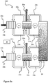
- Figure 3a shows an embodiment of a particle regeneration subsystem [210] coupled to a fuel storage tank [14] according to the invention.
- Subsystem [210] operatively connects a plurality of regenerator stacks.
- Subsystem [210] comprises a plurality of regenerator stacks [10a, 10b] and one or more intermediate tanks [12a, 12b].
- Subsystem [210] is operatively coupled with a fuel storage tank [14].
- Subsystem [210] is recharged by feeding metal ion-rich electrolyte from intermediate tanks [12a, 12b] into regenerator stacks [10a, 10b] through electrolyte conduits [20a, 20b].
- Energy is applied from external sources [42a, 42b] to generate metallic particles of a dendritic morphology and release oxygen gas as a by-product of the reaction.
- the oxygen gas [32a, 32b] travels through electrolyte conduit [21a, 21b] and exhausts to the atmosphere at intermediate tanks [12a, 12b].
- Intermediate tanks [12a, 12b] release generated oxygen at pressures close to or at atmospheric pressure.
- the electrolyte-particle slurry produced by regenerator stacks [10a, 10b] also passes through conduits [21a, 21b] to intermediate tanks [12a, 12b] and is then transferred to storage tank [14] through electrolyte conduits [23a, 23b].
- Intermediate tanks [12a, 12b] are refilled from fuel storage tank [14] through conduits [22a, 22b].
- the provision of separate intermediate tanks [12a, 12b] enables oxygen to be released at atmospheric pressure from both units while regenerator stack [10a] and corresponding intermediate tank [12a] are physically positioned independent of the position of regenerator stack [10b] and corresponding intermediate tank [12b].
- the vertical positions of regenerator stacks [10a, 10b] may be independent of each other.
- flow rates (Q1a, Q1b, Q2a and Q2b) are all independent of each other and may be supplied through one or more pumps or similar devices (not shown).
- flow rates (Q1a, Q1b, Q2a and Q2b) may be independently controlled by one or more control units [36] that control the one or more pumps or similar devices. This independence of flow rates provides multiple operational advantages. Since flow rates (Q1a) and (Q1b) are independent of each other, regenerator stacks [10a] and [10b] may be operated independently and the immediate flow rate experienced by regenerator stack [10a], for example, is not influenced by the immediate flow rate experienced by regenerator stack [10b].
- regenerator stacks [10a, 10b] are allowed to operate in a free-running mode according to the demands of each individual stack. In some embodiments, the operation of regenerator stacks [10a] and [10b] is synchronized to a common schedule. Such synchronization may permit the total electrical demand presented through connections [42a, 42b] to be more uniform.
- flow rates (Q1a) and (Q2a) are independent of each other, additional advantages may be obtained.
- the immediate flow rate (Q1a) required to operate regenerator stack [10a] is independent of the flow rate (Q2a) required to exchange the electrolyte-particle slurry collected in intermediate tank [12a] with fresh electrolyte present in fuel storage tank [14].
- flow rate (Q1a) in a particular mode of operation of regenerator stack [10a], it may be advantageous that flow rate (Q1a) is set to its maximum value while in another particular mode of operation of regenerator stack [10a], it may be advantageous that flow rate (Q1a) is set to zero.
- the immediate flow rate represented by (Q1a) may be varied over time but does not impose a corresponding requirement to alter the immediate value of flow rate (Q2a).
- Flow rate (Q2a) may be chosen to provide optimum conditions for exchange of electrolyte with storage tank [14].
- the electrolyte-particle slurry contained in fuel storage tank [14] is not overly disturbed. This condition may be achieved by controlling the total flow rate presented by the sum of flows (Q2a) and (Q2b) and is not influenced by the immediate flow rates presented by flows (Q1a) and (Q1b). In some embodiments, for the operation of particle regeneration subsystem [210], the flow rates represented by the sum of flow rates (Q1a) and (Q1b) may be significantly greater than the sum of flow rates (Q2a) and (Q2b).
- a further attribute of subsystem [210] is provided by the control of flow rates (Q1a) and (Q2a) in combination with the geometry of intermediate tank [12a]. It is advantageous for the operation of regenerator stack [10a] that a particle-lean flow of electrolyte may be recirculated back to regenerator stack [10a] through conduit [20a] and that a particle-rich flow of electrolyte is recirculated back to storage tank [14] through conduit [23a]. This condition may be substantially achieved by a variety of means.
- separate control of flow rates (Q1a) and (Q2a) may permit the concentration of particles in intermediate tank [12a] to be maintained at an acceptable level by replacing the particle-rich electrolyte delivered by flow (Q1a) through conduit [21a] with particle-lean electrolyte delivered by flow (Q2a) through conduit [22a].
- the electrolyte-particle slurry produced by regenerator stack [10a] may be allowed to settle and separate in intermediate tank [12a].
- Separate control of flow rates (Q1a) and (Q2a) may permit particle settling to occur and the geometry of intermediate tank [12a] enables flows (Q1a)and (Q2a) to be drawn from different regions of intermediate tank [12a].
- particle-lean flows of electrolyte may be withdrawn from upper regions of intermediate tanks [12a, 12b], and particle-rich flows of electrolyte may be withdrawn from lower regions of intermediate tanks [12a, 12b].
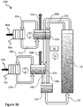
- Figure 3b shows another embodiment of a particle regeneration subsystem [220] coupled to a fuel storage tank [14] according to the invention.
- Subsystem [220] comprises regenerator stacks [10a, 10b] and intermediate tanks [12a, 12b].
- Subsystem [220] is operatively coupled with a fuel storage tank [14].
- a further intermediate tank [12d] is provided.
- the physical positioning of intermediate tank [12d] is such that it may be described as a sump tank and this terminology will now be adopted. Sump tank [12d] is thus included in flow (Q2) to provide additional flexibility in operation.
- Subsystem [220] operates similarly to that described for subsystem [210] with the exception of the manner in which intermediate tanks [12a, 12b] are refilled and drained.
- intermediate tanks [12a, 12b] are refilled from fuel storage tank [14] through conduits [22a, 22b].
- the intermediate tanks [12a, 12b] are drained to sump tank [12d] through conduits [28a, 28b].
- Sump tank [12d] may then be drained by returning the electrolyte-particle slurry to fuel storage tank [14] through conduit [23].
- a single flow (Q2) is used to refill a plurality of intermediate tanks.
- Conduits [22a, 22b] may be connected to a single pump (not shown) through a common manifold (not shown).
- flow rate (Q2) may be driven by two pumps or similar devices independent of the number of regenerator stacks serviced by said flow.
- flow rates (Q1a, Q1b, and Q2) may be independently controlled by one or more control units [36] that control the pumps or similar devices.
- Figure 3c shows a further embodiment of a particle regeneration subsystem [230] coupled to a fuel storage tank [14] according to the invention.
- Subsystem [230] comprises regenerator stacks [10a, 10b], intermediate tanks [12a, 12b], sump tank [12d] and fuel storage tank [14].
- Regenerator stacks [10a, 10b] are integrated with intermediate tanks [12a, 12b] thereby substantially eliminating the requirement for interconnecting conduits therebetween.
- Subsystem [230] is recharged by feeding metal ion-rich electrolyte from sump tank [12d] into intermediate tanks [12a, 12b] through electrolyte conduits [70a, 70b].
- Electrolyte then flows from intermediate tanks [12a, 12b] into regenerator stacks [10a, 10b] through internal paths.
- Energy is applied from external source [42a, 42b] to generate metallic particles of a dendritic morphology and release oxygen gas as a by-product of the reaction.
- the oxygen gas travels through the connected intermediate tanks [12a, 12b], and exhausts to the atmosphere [32a, 32b].
- Intermediate tanks [12a, 12b] release the generated oxygen at close to atmospheric pressure.
- the electrolyte-particle slurry is then transferred from intermediate tanks [12a, 12b] into sump tank [12d] through electrolyte conduits [71a, 71b].
- the electrolyte-particle slurry is then delivered from sump tank [12d] to fuel storage tank [14] through electrolyte conduit [73].
- the sump tank [12d] is recharged with fresh electrolyte through conduit [72].
- Sump tank [12d] also provides an alternative or additional mechanism [33] whereby oxygen may be released close to or at atmospheric pressure.
- regenerator stacks [10a, 10b] and intermediate tanks [12a, 12b] may be loosely integrated such that their individual functions are visually apparent or may be tightly integrated such that their individual functions are not visually apparent.
- the volume of electrolyte represented by intermediate tanks [12a, 12b] may be incorporated, in whole or in part, in the volume of electrolyte represented by regenerator stack [10].
- an individual pump or similar device (not shown) is used to provide flow (Q1a) for regenerator unit [10a] through conduit [70a]
- a further or similar device pump (not shown) is used to provide flow (Q1b) for regenerator unit [10b] through conduit [70b]
- a yet further pump or similar device (not shown) is used to drain sump tank [12d] through conduit [73] and a still further pump or similar device (not shown) is used to fill sump tank [12d] through conduit [72].
- one or more control units [36] independently control these pumps or similar devices.
- Figure 3d shows an embodiment of a particle regeneration subsystem [240] coupled to a fuel storage tank [14] according to the invention.
- Subsystem [240] comprises a plurality of regenerator stacks [10a, 10b], a header tank [15] and an intermediate tank [12d], operatively connected.
- the nature and physical positioning of intermediate tank [12d] is such that it may be described as an intermediate/sump tank and this terminology will now be adopted.
- Subsystem [240] is operatively coupled with a fuel storage tank [14].
- Subsystem [240] is recharged by feeding metal ion-rich electrolyte from intermediate/sump tank [12d] into header tank [15] through electrolyte conduit [120].
- Energy is applied to regenerator stacks [10a, 10b] from external sources [42a, 42b] to generate metallic particles of a dendritic morphology and release oxygen gas as a by-product of the reaction.
- the oxygen gas travels through electrolyte conduits [124a, 124b] to intermediate/sump tank [12d].
- the oxygen gas [32] exhausts to the atmosphere at intermediate/sump tank [12d].
- Intermediate/sump tank [12d] releases the generated oxygen at pressures close to or at atmospheric pressure.
- regenerator stacks [10a, 10b] also passes through conduits [124a, 124b] to intermediate/sump tank [12d] and is then transferred to storage tank [14] through electrolyte conduit [23].
- Intermediate/sump tank [12d] is refilled from fuel storage tank [14] through conduit [22].
- header tank [15] and intermediate/sump tank [12d] enables oxygen to be released at atmospheric pressure from both regenerator stacks while regenerator stack [10a] is physically positioned independent of the position of regenerator stack [10b].
- the vertical positions of regenerator stacks [10a, 10b] may be independent of each other.
- Regenerator stack [10a] is supplied with electrolyte from header tank [15] through electrolyte conduit [121a], valve [122a] and electrolyte conduit [123a].
- Regenerator stack [10b] is supplied with electrolyte from header tank [15] through electrolyte conduit [121b], valve [122b] and electrolyte conduit [123b].
- the provision of valves [122a, 122b] enables the flow of electrolyte to regenerator stacks [10a, 10b] to be controlled independently.
- flow rates (Q1 and Q2) are independent of each other and may be supplied through one or more pumps or similar devices (not shown).
- flow rates (Q1 and Q2) may be independently controlled by one or more control units [36] that control the one or more pumps or similar devices.
- flow rate (Q1) is itself composed of a plurality of conduit segments that can also be operated independently.
- Conduit segment [120] operates to supply electrolyte from intermediate/sump tank [12d] to header tank [15].
- Conduit segment [123a] operates to supply electrolyte from header tank [15] to regenerator stack [10a].
- Conduit segment [124a] operates to supply electrolyte-particle slurry and generated oxygen from regenerator stack [10a] to intermediate/sump tank [12d].
- Conduit segment [123b] operates to supply electrolyte from header tank [15] to regenerator stack [10b].
- Conduit segment [124b] operates to supply electrolyte-particle slurry and generated oxygen from regenerator stack [10b] to intermediate/sump tank [12d]. This independence of electrolyte flow provides multiple operational advantages.
- regenerator stacks [10a] and [10b] may be operated independently and the immediate flow rate experienced by regenerator stack [10a], for example, is not influenced by the immediate flow rate experienced by regenerator stack [10b].
- regenerator stacks [10a, 10b] are allowed to operate in a free-running mode according to the demands of each individual stack.
- the operation of regenerator stacks [10a] and [10b] is synchronized to a common schedule. Such synchronization may permit the total electrical demand presented through connections [42a, 42b] to be more uniform.
- header tank [15] is supplied with electrolyte from intermediate/sump tank [12d] by a single pump (not shown) operating through conduit [120].
- header tank [15] is supplied with electrolyte from intermediate/sump tank [12d] by a plurality of pumps operating through one or a plurality of conduits.
- regenerator stacks [10a, 10b] are supplied with electrolyte through conduits [123a, 123b] by the force of gravity operating on the electrolyte contained in header tank [15].
- flow rates (Q1) and (Q2) are independent of each other, additional advantages may be obtained.
- the immediate flow rate (Q1) required to operate regenerator stacks [10a, 10b] is independent of the flow rate (Q2) required to exchange the electrolyte-particle slurry collected in intermediate/sump tank [12d] with fresh electrolyte present in fuel storage tank [14].
- flow rate (Q1) in a particular mode of operation of regenerator stacks [10a, 10b], it may be advantageous that flow rate (Q1) is set to its maximum value while in another particular mode of operation of regenerator stacks [10a, 10b], it may be advantageous that flow rate (Q1) is set to zero.
- the immediate flow rate represented by (Q1) may be varied over time but does not impose a corresponding requirement to alter the immediate value of flow rate (Q2).
- Flow rate (Q2) may be chosen to provide optimum conditions for exchange of electrolyte with storage tank [14].
- the electrolyte-particle slurry contained in fuel storage tank [14] is not overly disturbed. This condition may be achieved by limiting the flow rate presented by (Q2) and is not influenced by the immediate flow rate presented by flow (Q1). In some embodiments, for the operation of particle regeneration subsystem [240], the total flow rate represented by (Q1) may be significantly greater than the flow rate represented by (Q2).
- a further attribute of subsystem [240] is provided through the control of flow rates (Q1) and (Q2) in combination with the geometry of intermediate/sump tank [12d]. It is advantageous for the operation of regenerator stacks [10a, 10b] that a particle-lean flow of electrolyte may be delivered to regenerator stacks [10a, 10b] through conduits [123a, 123b] and that a particle-rich flow of electrolyte is recirculated back to storage tank [14] through conduit [23]. This condition may be substantially achieved by a variety of means.
- separate control of flow rates (Q1) and (Q2) may permit the concentration of particles in intermediate/sump tank [12d] to be maintained at an acceptable level by replacing the particle-rich electrolyte delivered by flow (Q1) through conduits [124a, 124b] with particle-lean electrolyte delivered by flow (Q2) through conduit [22].
- the electrolyte-particle slurry produced by regenerator stacks [10a, 10b] may be allowed to settle and separate in intermediate/sump tank [12d].
- Separate control of flow rates (Q1) and (Q2) may permit particle settling to occur and the geometry of intermediate/sump tank [12d] enables flows (Q1) and (Q2) to be drawn from different regions of intermediate/sump tank [12d].
- particle-lean flows of electrolyte may be withdrawn from the upper regions of intermediate/sump tank [12d]
- particle-rich flows of electrolyte may be withdrawn from lower regions of intermediate/sump tank [12d].
- Figure 3e is a block diagram of a particle regeneration subsystem according to an embodiment of the invention, showing a header tank, an intermediate/sump tank and a plurality of regenerator stacks operatively connected.
- Subsystem [250] comprises all the elements of subsystem [240] and further comprises the addition of check valve [130] to header tank [15].
- the inclusion of check valve [130] has advantage in reducing the energy required to fill header tank [15] with electrolyte.
- valves [122a, 122b] When the system is being primed with electrolyte, valves [122a, 122b] are closed, check valve [130] is open and electrolyte is supplied from intermediate/sump tank [12d] to header tank [15] through conduit [120] by a pump (not shown). During this process, air in header tank [15] is displaced by electrolyte and is exhausted to the atmosphere through check valve [130]. Once header tank [15] is full of electrolyte, the reseal pressure of check valve [130] is reached and the check valve is closed.
- header tank [15] When it is necessary to flow electrolyte through, for example, regenerator [10a], valve [122a] is opened and check valve [130] remains closed.
- the pressure of fluid in header tank [15] causes a flow of electrolyte through elements [121a, 122a, 123a, 10a and 124a].
- Conduit [124a] is sized such that closed channel flow is achieved.
- the suction caused by closed channel flow causes replacement fluid to be drawn into header tank [15] through conduit [120], thereby reducing the pumping power otherwise required to refill header tank [15].
- header tank [15] may be maintained in a substantially full condition and may operate as a manifold for supplying electrolyte to a plurality of regenerator stacks.
- Each of the arrows indicating flow between components in Figures 1 , 2 , and 3a to 3e is independently selectable by one or more control units to optimize electro-depositing metallic particulate material within the regenerator stack and/or generating electricity by discharging the metallic particulate material within the power generation stack.
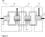
- FIG. 4 shows a regenerative fuel cell system [200] according to an embodiment of the invention.
- the components of system [200] are partitioned into separate physical structures. Each structure may be assembled independently and may be described as a compartment, cabinet, rack, bay or similar embodiment.
- one or more regenerator stacks [10] and intermediate tanks [12] are located within particle regeneration subsystem (PRS) [50]
- one or more fuel storage tanks [14] are located within fuel storage subsystem (FSS) [52]
- FPS fuel storage subsystem
- PPS power generation subsystem
- each structure [50, 52, 54] hereinafter referred to as a bay, may also be duplicated to produce an even larger system.
- each structure [50, 52, 54] may be positioned independently and may be separated from each other.
- each structure [50, 52, 54] is assembled within a separate intermodal container and said containers are located close to one another.
- each intermodal container may be located at a separate site.
- FIG. 5a shows a particle regeneration subsystem (PRS) bay [50] according to an embodiment of the invention.
- PRS bay [50] houses one or more regenerator stacks [10] and associated components.
- the PRS operates as described previously; the PRS regenerates stored energy by feeding metal ion-rich electrolyte into regenerator stack [10] through electrolyte conduit [20] and through intermediate tank [12].
- Intermediate tank [12] is integral to releasing the generated oxygen at close to atmospheric pressure.
- Energy is applied from an external source [42] to generate metallic particles of a dendritic morphology and release oxygen gas as a by-product of the reaction.
- the oxygen gas travels through electrolyte conduit [21], through the connected intermediate tank [12], and exhausts to the atmosphere [32].
- each complete regenerator stack and associated intermediate tank is housed in a sub-compartment [60a, 60b, 60c] of PRS bay [50].
- the physical arrangement of each sub-compartment [60a] can be placed independently of additional sub-compartments [60b, 60c] through the incorporation of the individual intermediate tanks [12].
- the number of regenerator stacks located in a single bay may range from one to sixteen and the number of electrolytic cells in each regenerator stack may range from one to forty or more.
- the capacity of the PRS bay may exceed that of the PGS bay.
- the ratio of PRS power to PGS power may range from 8:1 to 1:8. In some embodiments, the ratio may be 8:1, 4:1, 2:1, 1:1, 1:2, 1:4 or 1:8.
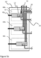
- FIG. 5b shows a particle regeneration subsystem (PRS) bay [50'] according to an embodiment of the invention.
- PRS bay [50'] houses one or more integrated regenerator stacks [10]/intermediate tanks [12] and associated components.
- the PRS operates substantially as described previously; the PRS regenerates stored energy by feeding metal ion-rich electrolyte into an integrated regenerator stack [10]/intermediate tank [12] through electrolyte conduit [22].
- the integrated regenerator stack [10]/intermediate tank [12] releases the generated oxygen at pressures close to atmospheric pressure. Energy is applied from an external source [42] to generate metallic particles of a dendritic morphology and release oxygen gas which exhausts to the atmosphere [32].
- each complete regenerator stack and integrated intermediate tank is housed in a sub-compartment [60a, 60b, 60c] of particle regeneration subsystem bay [50'].
- the physical arrangement of each sub-compartment [60a] can be placed independently of additional sub-compartments [60b, 60c] through incorporation of the integrated intermediate tanks [12].
- FIG. 5c shows a particle regeneration subsystem (PRS) bay [50"] according to an embodiment of the invention.
- PRS bay [50"] houses one or more integrated regenerator stacks [10]/intermediate tanks [12] and associated components, and further utilizes a shared sump tank [12d].
- the PRS operates substantially as described previously; the PRS regenerates stored energy by feeding metal ion-rich electrolyte from sump tank [12d] into integrated regenerator stack [10]/intermediate tank [12] through electrolyte conduit [70]. Electrical energy is applied from an external source [42] to generate metallic particles of a dendritic morphology and release oxygen gas as a by-product of the reaction.
- the oxygen gas travels through integrated regenerator stack [10]/ intermediate tank [12] and electrolyte-particle slurry conduit [71] and exhausts to the atmosphere [33] at sump tank [12d].
- the sump tank releases generated oxygen at pressures close to atmospheric pressure.
- the electrolyte-particle slurry is then transferred to fuel storage tank [14] through electrolyte conduit [23].
- Sump tank [12d] is refilled from fuel storage tank [14] through conduit [22].
- Each complete regenerator stack and integrated intermediate tank is housed in a sub-compartment [60a, 60b, 60c] of particle regeneration subsystem bay [50"].
- each sub-compartment [60a] can be placed independently of additional sub-compartments [60b, 60c] through incorporation of the integrated intermediate tanks [12].
- the shared sump tank [12d] is located in the lowest compartment [60d] or in a position equivalent to the lowest [60c] regenerator stack in relation to gravitational positioning.
- FIG. 5d shows a particle regeneration subsystem (PRS) bay [50'"] according to an embodiment of the invention.
- PRS bay [50'"] houses one or more regenerator stacks [10] and associated components, and further utilizes a shared header tank [15] and intermediate/sump tank [12d].
- the PRS operates substantially as described previously; the PRS regenerates stored energy by feeding metal ion-rich electrolyte from intermediate/sump tank [12d] into header tank [15] and thereafter to regenerator stack [10a] through electrolyte conduit [121a], valve [122a] and electrolyte conduit [123a]. Electrical energy is applied from an external source [42a] to generate metallic particles of a dendritic morphology and release oxygen gas as a by-product of the reaction.
- regenerator stack [10a] and electrolyte conduit [124a] The oxygen gas travels through regenerator stack [10a] and electrolyte conduit [124a] and exhausts to the atmosphere [33] at intermediate/sump tank [12d].
- the intermediate/sump tank releases generated oxygen at pressures close to atmospheric pressure.
- the electrolyte-particle slurry produced by regenerator stack [10a] also passes through electrolyte conduit [124a] to intermediate/sump tank [12d] and is then transferred to fuel storage tank [14] through electrolyte conduit [23].
- Intermediate/sump tank [12d] is refilled from fuel storage tank [14] through conduit [22].
- a similar operation may be followed for each additional regenerator stack contained within PRS bay [50'"].
- Each regenerator stack is housed in a sub-compartment [60a, 60b, 60c] of particle regeneration subsystem bay [50'"].
- the physical arrangement of each sub-compartment [60a] can be placed independently of additional sub-compartments [60b, 60c].
- the shared intermediate/sump tank [12d] is located in the lowest compartment [60d] or in a position equivalent to the lowest [60c] regenerator stack in relation to gravitational positioning.
- the shared header tank [15] is located above the highest compartment [60a] in relation to gravitational positioning.
- header tank [15] is open to the atmosphere and the removal of metallic particles from regenerator stack [10a] is governed by the fluid pressure developed through header tank [15], conduit [121a], valve [122a] and conduit [123a].
- conduit [124a] may be sized such that closed channel flow is achieved soon after valve [122a] is opened whereupon the fluid suction developed in conduit [124a] may augment the fluid pressure developed above regenerator stack [10a].
- the fluid flow available for particle removal is substantially independent of the relative height of a regenerator stack with respect to the header and intermediate/sump tanks.
- the number of regenerator stacks located in a single bay may range from one to sixteen and the number of electrolytic cells in each regenerator stack may range from one to forty or more.
- the capacity of the PRS bay may exceed that of the PGS bay.
- the ratio of PRS power to PGS power may range from 8:1 to 1:8. In some embodiments, the ratio may be 8:1, 4:1, 2:1, 1:1, 1:2, 1:4 or 1:8.
- FIG 6 shows a fuel storage subsystem (FSS) bay [52] according to an embodiment of the invention.
- FSS bay [52] houses the fuel storage tank subsystem.
- the FSS operates as described previously; for regeneration, the metal ion-rich electrolyte is fed into the PRS regenerator bay (detailed in Figure 3a ) through electrolyte conduits [22].
- Electrolyte-particle slurry is transferred to fuel storage tank [14] through electrolyte slurry conduits [23] after exiting the PRS regenerator bay (detailed in Figures 5a , 5b and 5c ).
- the system is discharged by feeding electrolyte-particle slurry through an electrolyte slurry conduit [24] into the PGS power generation bay (detailed in Figure 7 ).
- the electrolyte fuel stream, lean with particles and rich with potassium zincate, is fed back to fuel storage tank [14] from the PGS bay (detailed in Figure 7 ) through an electrolyte conduit [25].
- the number of PRS bays connected to a single FSS bay may range from one to four and the number of PGS bays connected to a single FSS bay may range from one to four.
- the volume of electrolyte-particle slurry contained by said FSS bay may range from 100 litres to 1000 litres.
- the energy capacity of said FSS bay may range from 10 kWh to 100 kWh.
- the volume of electrolyte-particle slurry contained by said FSS bay may range from 1000 litres to 10,000 litres and the energy capacity of said FSS bay may range from 100 kWh to 1000 kWh.
- FIG. 7 shows a PGS power generation subsystem bay [54] according to an embodiment of the invention.
- PGS bay [54] houses one or more power generation stacks [16].
- the PGS operates as described previously; the PGS is discharged by feeding electrolyte-particle slurry through electrolyte conduit [24] into power generation stack [16].
- Oxygen from the air [34] is also fed into the power generation stack [16] which reacts with the metallic particulate fuel to provide power to a load [44].
- the electrolyte fuel stream, lean with metallic particles and rich with metallic ions, is fed back to the FSS bay [52] through electrolyte conduit [25].
- the number of power generation stacks located in a single bay may range from one to sixteen and the number of fuel cells in each power generation stack may range from one to fifty.
- the capacity of the PGS bay may exceed that of the PRS bay.
- the ratio of PGS power to PRS power may range from 8:1 to 1:8. In some embodiments, said ratio may be 8:1, 4:1, 2:1, 1:1, 1:2 1:4 or 1:8.
- Figure 8 is a state diagram describing the major operating modes of the system.
- the four states of Standby [610], Discharging [620], Hibernating [630] and Recharging [640] represent the normal or "successful" flow of events.
- the Standby state [610] is the system state where the FSS tank is fully charged with metallic particulate fuel and the system is receiving power from the source.
- the Standby state is the default state for the system; its primary purpose is to monitor the system for faults as well as to monitor the source power for faults and to then transition into the Discharging state [620].
- the Discharging state [620] is the state in which the power generation subsystem uses the metallic particulate fuel from the storage tank and oxidant from the atmosphere to generate electricity to deliver to the load.
- the Hibernation state [630] is the state in which the system is fully discharged having consumed all of the available metallic particulate fuel and can no longer deliver power to the load, and no source power has been restored to the system.
- the Recharging state [640] is the state in which the particle regeneration subsystem operates to grow metallic particulate fuel and recharges the system's capacity for generating power.
- the Out Of Service state [600] is a maintenance and alarm state in which the system waits for a service action to be performed before resuming operation. State [600] may be entered from any other state [660] when an abnormal event is detected.
- the Warming state [650] is an intermediate state that is entered when the external temperature is very low and the system is unable to maintain the minimum temperature for operation.
- fluid flow (Q3) is activated to deliver a flow of bearer electrolyte to one or a plurality of power generation stacks [16] and the spent fuel is returned to fuel storage tank [14].
- Fluid flows (Q1 and Q2) remain idle. The system may remain in this state until all the fuel has been used whereupon it will transition to the Hibernating state [630]. If the source power is restored before all the available fuel is consumed then the system will transition to the Recharging state [640].
- fluid flows (Q1 and Q2) are activated to deliver a flow of bearer electrolyte to one or a plurality of regenerator stacks [10].
- the incorporation of one or a plurality of intermediate tanks [12] enables the reactant products to be substantially separated at atmospheric pressure; the oxygen reactant product [32] is released to the atmosphere while the metallic particulate fuel is returned to fuel storage tank [14].
- the independence of fluid flows (Q1) and (Q2) provides further flexibility to the operation of the system.
- fluid flow may deliver particulate-rich slurry to sump tank [12d] when source power [42] is present or has been recently present and may deliver particulate-lean slurry to sump tank [12d] otherwise.
- Fluid flow (Q2) may be activated to exchange the electrolyte slurry present in sump tank [12d] with the bearer-electrolyte present in fuel storage tank [14] at time periods and flow rates that are optimum for said exchange and are not directly related to the immediate status of flow rate (Q1).
- sump tank [12d] may also be utilized to promote substantial settling of the metallic particulate fuel such that particulate-rich electrolyte is returned to fuel storage tank [14] through conduit [73] and is replaced by particulate-lean electrolyte supplied through conduit [72].
Landscapes
- Chemical & Material Sciences (AREA)
- Life Sciences & Earth Sciences (AREA)
- Engineering & Computer Science (AREA)
- Manufacturing & Machinery (AREA)
- Sustainable Development (AREA)
- Sustainable Energy (AREA)
- Chemical Kinetics & Catalysis (AREA)
- Electrochemistry (AREA)
- General Chemical & Material Sciences (AREA)
- Dispersion Chemistry (AREA)
- Fuel Cell (AREA)
Claims (15)
- Energiespeichersystem, das Folgendes umfasst:ein Partikelregenerationssubsystem zum Anwenden elektrischer Energie, um metallischen partikelförmigen Brennstoff zu regenerieren, wobei das Partikelregenerationssubsystem einen oder mehrere Regeneratorstapel umfasst, die, wenn elektrische Energie angewendet wird, den metallischen partikelförmigen Brennstoff regenerieren und einen gasförmigen Ausfluss produzieren;ein Brennstoffspeichersubsystem zum Speichern eines metallischen partikelförmigen Brennstoffs, wobei das Brennstoffspeichersubsystem mit dem Partikelregenerationssubsystem in Fluidverbindung steht; undein Stromerzeugungssubsystem zum Produzieren elektrischer Energie aus dem metallischen partikelförmigen Brennstoff, wobei das Stromerzeugungssubsystem mit dem Brennstoffspeichersubsystem in Fluidverbindung steht;ein Trägerelektrolyt zum Transportieren des metallischen partikelförmigen Brennstoffs durch das Partikelregenerationssubsystem, das Brennstoffspeichersubsystem und das Stromerzeugungssubsystem;eine Steuerungseinheit, die konfiguriert ist, um den Fluss des Trägerelektrolyts zwischen dem Partikelregenerationssubsystem und dem Brennstoffspeichersubsystem sowie dem Brennstoffspeichersubsystem und dem Stromerzeugungssubsystem unabhängig zu steuern;einen oder mehrere Zwischentanks in Fluidverbindung zwischen dem einen oder den mehreren Regeneratorstapeln und dem Brennstoffspeichersubsystem, wobei der eine oder die mehreren Zwischentanks konfiguriert sind, um den gasförmigen Ausfluss in die Atmosphäre freizusetzen.
- Energiespeichersystem gemäß Anspruch 1, wobei der metallische partikelförmige Brennstoff Zinkpartikel umfasst, die eine dendritische Morphologie und eine Größenverteilung im Bereich von 10 bis 1000 Mikrometer aufweisen.
- Energiespeichersystem gemäß einem der Ansprüche 1 oder 2, wobei der eine oder die mehreren Zwischentanks konfiguriert sind, um den metallischen partikelförmigen Brennstoff von dem Trägerelektrolyt zu trennen, optional durch Schwerkraftabsetzen.
- Energiespeichersystem gemäß einem der Ansprüche 1 bis 3, wobei mindestens einer des einen oder der mehreren Zwischentanks als Kopftank konfiguriert ist, der physisch über dem einen oder den mehreren Regeneratorstapeln positioniert ist, wobei das System ferner eine erste Leitung mit einem ersten Ventil zwischen dem Kopftank und einem ersten Regeneratorstapel und eine zweite Leitung mit einem zweiten Ventil zwischen dem Kopftank und einem zweiten Regeneratorstapel umfasst, wobei das erste und zweite Ventil unabhängig betrieben werden können, um eine unabhängige Steuerung von Elektrolytfluss von dem Kopftank an den ersten und zweiten Regeneratorstapel zu erlauben, wobei der Kopftank optional ein Rückschlagventil umfasst, das konfiguriert ist, um einen geschlossenen Kanalfluss zwischen dem Kopftank und dem ersten und zweiten Regeneratorstapel zu erlauben.
- Energiespeichersystem gemäß einem der Ansprüche 1 bis 4, wobei die Steuerungseinheit konfiguriert ist, um den Fluss des Trägerelektrolyts zwischen einem ersten des einen oder der mehreren Regeneratorstapeln und einem ersten des einen oder der mehreren Zwischentanks sowie einem zweiten des einen oder der mehreren Regeneratorstapeln und einem zweiten des einen oder der mehreren Zwischentanks zu steuern.
- Verfahren zum Speichern elektrischer Energie, das Folgendes umfasst:(a) Empfangen elektrischer Energie von einer externen Quelle;(b) Elektroablagern eines metallischen partikelförmigen Materials innerhalb eines Regeneratorstapels durch Anwenden der elektrischen Energie;(c) Zuführen des metallischen partikelförmigen Materials in einem Trägerelektrolyt von dem Regeneratorstapel an einen Brennstoffspeichertank mit einer ersten Flussrate;(d) Speichern des metallischen partikelförmigen Materials in dem Trägerelektrolyt in dem Brennstoffspeichertank;(e) Zuführen des gespeicherten metallischen partikelförmigen Materials in dem Trägerelektrolyt von dem Brennstoffspeichertank an einen Stromerzeugungsstapel mit einer zweiten Flussrate;(f) Erzeugen von Elektrizität durch Entladen des metallischen partikelförmigen Materials innerhalb des Stromerzeugungsstapels;(g) Zurückleiten von metallionenreichem Elektrolyt von dem Stromerzeugungsstapel an den Brennstoffspeichertank mit einer dritten Flussrate; und(h) Zurückleiten von metallionenreichem Elektrolyt von dem Brennstoffspeichertank an den Regeneratorstapel mit einer vierten Flussrate;wobei die erste Flussrate und die vierte Flussrate unabhängig selektierbar sind, um Schritt (b) zu optimieren, und die zweite Flussrate und die dritte Flussrate unabhängig selektierbar sind, um Schritt (f) zu optimieren und um ein unabhängiges Skalieren des Regeneratorstapels, des Brennstoffspeichertanks und des Stromerzeugungsstapels zu erlauben.
- Verfahren zum Speichern elektrischer Energie gemäß Anspruch 6, wobei das metallische partikelförmige Material Zinkpartikel umfasst, die eine dendritische Morphologie und eine Größenverteilung im Bereich von 10 bis 1000 Mikrometer aufweisen.
- Verfahren zum Speichern elektrischer Energie gemäß einem der Ansprüche 6 oder 7, wobei ein Zwischentank zwischen dem Regeneratorstapel und dem Brennstoffspeichertank bereitgestellt ist, wobei das Verfahren ferner das Ableiten von Sauerstoff von dem Elektrolyt von dem Regeneratorstapel an dem Zwischentank umfasst, um ein Aufbauen von Gegendruck des Sauerstoffs in dem Regeneratorstapel zu verhindern.
- Verfahren zum Speichern elektrischer Energie gemäß Anspruch 8, das das Bereitstellen einer Vielzahl von Regeneratorstapeln umfasst, wobei jeder Regeneratorstapel auf einer unterschiedlichen vertikalen Höhe in Bezug auf den Brennstoffspeichertank physisch positionierbar ist, wobei das Verfahren optional ferner das Schwerkraftabsetzen des metallischen partikelförmigen Materials von dem Regeneratorstapel an dem Zwischentank umfasst, um einen konzentrierten Fluss des metallischen partikelförmigen Materials zu dem Brennstoffspeichertank bereitzustellen.
- Verfahren zum Speichern elektrischer Energie gemäß einem der Ansprüche 8 oder 9, wobei Schritt (c) das Zuführen des metallischen partikelförmigen Materials in dem Elektrolyt von dem Regeneratorstapel an den Zwischentank mit einer fünften Flussrate und das Zuführen des metallischen partikelförmigen Materials in dem Elektrolyt von dem Zwischentank an den Brennstoffspeichertank mit einer sechsten Flussrate umfasst, wobei die fünfte Flussrate und die sechste Flussrate unabhängig selektierbar sind, um Schritt (b) und/oder Schritt (c) zu optimieren und um ein unabhängiges Skalieren des Regeneratorstapels, des Zwischentanks und des Brennstoffspeichertanks zu erlauben.
- Verfahren zum Speichern elektrischer Energie gemäß Anspruch 10, wobei Schritt (c) ferner das Zuführen des metallischen partikelförmigen Materials in dem Elektrolyt von dem Zwischentank an einen Sumpftank mit einer siebten Flussrate und von dem Sumpftank an den Brennstoffspeichertank mit einer achten Flussrate umfasst, wobei die siebte Flussrate und die achte Flussrate selektierbar sind, um Schritt (b) und/oder Schritt (c) zu optimieren und um ein unabhängiges Skalieren des Regeneratorstapels, des Zwischentanks, des Sumpftanks und des Brennstoffspeichertanks zu erlauben, wobei Schritt (c) optional ferner das Zuführen des metallischen partikelförmigen Materials in dem Elektrolyt von einem zweiten Zwischentank an den Sumpftank mit einer elften Flussrate und von dem Sumpftank an den Brennstoffspeichertank mit der achten Flussrate umfasst,
wobei die achte Flussrate und die elfte Flussrate unabhängig selektierbar sind, um Schritt (b) und/oder Schritt (c) zu optimieren und um ein unabhängiges Skalieren des Regeneratorstapels, des Zwischentanks, des Sumpftanks und des Brennstoffspeichertanks zu erlauben. - Verfahren zum Speichern elektrischer Energie gemäß Anspruch 10, wobei Schritt (c) das Zuführen des metallischen partikelförmigen Materials in dem Elektrolyt von einem zweiten Regeneratorstapel an einen zweiten Zwischentank mit einer neunten Flussrate und das Zuführen des metallischen partikelförmigen Materials in dem Elektrolyt von dem zwei Zwischentank an den Brennstoffspeichertank mit einer zehnten Flussrate umfasst, wobei die neunte Flussrate und die zehnte Flussrate unabhängig selektierbar sind, um Schritt (b) und/oder Schritt (c) zu optimieren und um ein unabhängiges Skalieren des Regeneratorstapels, des Zwischentanks und des Brennstoffspeichertanks zu erlauben.
- Verfahren gemäß Anspruch 11, das das Ableiten von Sauerstoff von dem Elektrolyt von dem Regeneratorstapel an dem Sumpftank umfasst, ferner umfassend das physische Positionieren des Sumpftanks mindestens so niedrig wie ein physisch am niedrigsten positionierter Regeneratorstapel.
- Verfahren zum Speichern elektrischer Energie gemäß einem der Ansprüche 8 oder 9, wobei:Schritt (h) das Zurückleiten von metallionenreichem Elektrolyt von dem Brennstoffspeichertank an den Zwischentank mit einer zwölften Flussrate und das Zurückleiten von metallionenreichem Elektrolyt von dem Zwischentank an den Regeneratorstapel mit einer dreizehnten Flussrate umfasst, wobei die zwölfte Flussrate und die dreizehnte Flussrate unabhängig selektierbar sind, um Schritt (h) zu optimieren und um ein unabhängiges Skalieren des Regeneratorstapels, des Zwischentanks und des Brennstoffspeichertanks zu erlauben; oderder Zwischentank einen Kopftank und einen Sumpftank umfasst, wobei Schritt (h) ferner das Zurückleiten von metallionenreichem Elektrolyt von dem Sumpftank an den Kopftank mit einer vierzehnten Flussrate und von dem Kopftank an den Regeneratorstapel mit einer fünfzehnten Flussrate umfasst, wobei die vierzehnte Flussrate und die fünfzehnte Flussrate unabhängig selektierbar sind, um Schritt (h) zu optimieren und um ein unabhängiges Skalieren des Regeneratorstapels, des Sumpftanks, des Kopftanks und des Brennstoffspeichertanks zu erlauben, ferner umfassend das physische Positionieren des Kopftanks höher als der physisch am höchsten positionierte Regeneratorstapel und das physische Positionieren des Sumpftanks niedriger als der physisch am niedrigsten positionierte Regeneratorstapel; oderder Zwischentank einen Kopftank und einen Sumpftank umfasst, wobei Schritt (h) das Zurückleiten von metallionenreichem Elektrolyt von dem Sumpftank an den Kopftank mit einer vierzehnten Flussrate und das Zurückleiten von metallionenreichem Elektrolyt von dem Kopftank an einen ersten Regeneratorstapel mit einer achtzehnten Flussrate und von dem Kopftank an einen zweiten Regeneratorstapel mit einer neunzehnten Flussrate umfasst, wobei die achtzehnte Flussrate und die neunzehnte Flussrate unabhängig selektierbar sind, um Schritt (b) und/oder Schritt (f) zu optimieren und um ein unabhängiges Skalieren der Regeneratorstapel, des Sumpftanks, des Kopftanks und des Brennstoffspeichertanks zu erlauben, ferner umfassend das physische Positionieren des Kopftanks höher als der physisch am höchsten positionierte Regeneratorstapel und das physische Positionieren des Sumpftanks niedriger als der physisch am niedrigsten positionierte Regeneratorstapel, und wobei das Verfahren optional ferner Folgendes umfasst: einen Vorbereitungsschritt zum Einstellen der achtzehnten Flussrate und der neunzehnten Flussrate auf Null und Erlauben, dass der Sumpftank den Kopftank mit metallionenreichem Elektrolyt füllt, um Luft in dem Kopftank zu verdrängen, durch Öffnen eines Rückschlagventils in dem Kopftank und dann anschließendes Schließen des Rückschlagventils und Erlauben, dass die achtzehnte Flussrate und/oder die neunzehnte Flussrate durch den geschlossenen Kanalfluss fortgesetzt wird, wobei der geschlossene Kanalfluss auch zu der vierzehnten Flussrate beiträgt.
- Verfahren zum Speichern elektrischer Energie gemäß Anspruch 14, wobei Schritt (h) das Zurückleiten von metallionenreichem Elektrolyt von dem Brennstoffspeichertank an einen zweiten Zwischentank mit einer sechzehnten Flussrate und das Zurückleiten von metallionenreichem Elektrolyt von dem zweiten Zwischentank an einen zweiten Regeneratorstapel mit einer siebzehnten Flussrate umfasst, wobei die sechzehnte Flussrate und die siebzehnte Flussrate unabhängig selektierbar sind, um Schritt (h) zu optimieren und um ein unabhängiges Skalieren des Regeneratorstapels, des zweiten Zwischentanks und des Brennstoffspeichertanks zu erlauben.
Applications Claiming Priority (2)
| Application Number | Priority Date | Filing Date | Title |
|---|---|---|---|
| US201662367768P | 2016-07-28 | 2016-07-28 | |
| PCT/CA2017/050895 WO2018018145A1 (en) | 2016-07-28 | 2017-07-25 | Systems and methods for fuel cells energy storage and recovery |
Publications (3)
| Publication Number | Publication Date |
|---|---|
| EP3491694A1 EP3491694A1 (de) | 2019-06-05 |
| EP3491694A4 EP3491694A4 (de) | 2020-07-01 |
| EP3491694B1 true EP3491694B1 (de) | 2021-12-08 |
Family
ID=61015266
Family Applications (1)
| Application Number | Title | Priority Date | Filing Date |
|---|---|---|---|
| EP17833146.8A Active EP3491694B1 (de) | 2016-07-28 | 2017-07-25 | Systeme und verfahren zur speicherung und wiedergewinnung von energie in brennstoffzellen |
Country Status (4)
| Country | Link |
|---|---|
| US (2) | US11133520B2 (de) |
| EP (1) | EP3491694B1 (de) |
| CA (1) | CA3031431C (de) |
| WO (1) | WO2018018145A1 (de) |
Families Citing this family (4)
| Publication number | Priority date | Publication date | Assignee | Title |
|---|---|---|---|---|
| US20250323277A1 (en) * | 2022-06-08 | 2025-10-16 | E-Zinc Inc. | Charge cathode assembly with embedded electrode material for use in an electrochemical cell |
| WO2024007081A1 (en) * | 2022-07-06 | 2024-01-11 | Zinc8 Energy Solutions Inc. | Particle suspension concentration control in a fluid fuel mixture for an electrochemical cell |
| WO2024103174A1 (en) * | 2022-11-16 | 2024-05-23 | Zinc8 Energy Solutions Inc. | Electrochemical cell bypass control |
| EP4730449A1 (de) * | 2024-10-17 | 2026-04-22 | Centre National de la Recherche Scientifique | Redox-durchflussbatterie |
Family Cites Families (8)
| Publication number | Priority date | Publication date | Assignee | Title |
|---|---|---|---|---|
| US20030035984A1 (en) | 2001-08-15 | 2003-02-20 | Colborn Jeffrey A. | Metal fuel cell system for providing backup power to one or more loads |
| US20030134172A1 (en) * | 2002-01-11 | 2003-07-17 | Grande Wendy C. | Integrated fuel cell and electrochemical power system employing the same |
| US20040053132A1 (en) * | 2002-09-12 | 2004-03-18 | Smedley Stuart I. | Improved fuel for a zinc-based fuel cell and regeneration thereof |
| US7575822B2 (en) | 2003-04-09 | 2009-08-18 | Bloom Energy Corporation | Method of optimizing operating efficiency of fuel cells |
| US7250231B2 (en) * | 2003-06-09 | 2007-07-31 | Idatech, Llc | Auxiliary fuel cell system |
| DE102007011311A1 (de) * | 2006-12-22 | 2008-06-26 | Mtu Cfc Solutions Gmbh | Vanadium-Redox-Batterie und Verfahren zu ihrem Betrieb |
| US20140193724A1 (en) | 2013-01-04 | 2014-07-10 | Ashlawn Energy, LLC | Gravity feed flow battery system and method |
| FI125195B (en) * | 2014-06-04 | 2015-06-30 | Michael Harold Barker | Copper powder hybrid redox flow accumulator method and system for electrical energy storage |
-
2017
- 2017-07-25 WO PCT/CA2017/050895 patent/WO2018018145A1/en not_active Ceased
- 2017-07-25 EP EP17833146.8A patent/EP3491694B1/de active Active
- 2017-07-25 CA CA3031431A patent/CA3031431C/en active Active
- 2017-07-25 US US16/320,839 patent/US11133520B2/en active Active
-
2021
- 2021-06-21 US US17/352,558 patent/US11600840B2/en active Active
Also Published As
| Publication number | Publication date |
|---|---|
| EP3491694A1 (de) | 2019-06-05 |
| US11133520B2 (en) | 2021-09-28 |
| EP3491694A4 (de) | 2020-07-01 |
| US20210376368A1 (en) | 2021-12-02 |
| CA3031431C (en) | 2023-08-08 |
| WO2018018145A1 (en) | 2018-02-01 |
| US11600840B2 (en) | 2023-03-07 |
| CA3031431A1 (en) | 2018-02-01 |
| US20190165403A1 (en) | 2019-05-30 |
Similar Documents
| Publication | Publication Date | Title |
|---|---|---|
| US11600840B2 (en) | Systems and methods for fuel cells energy storage and recovery | |
| CN102576893B (zh) | 采用氧化还原液流电池的燃料系统 | |
| Smedley et al. | A regenerative zinc–air fuel cell | |
| US9231268B2 (en) | Flow battery system with standby mode | |
| EP2532043B1 (de) | Elektrochemische zelle mit einem diffusor | |
| TWI523299B (zh) | 電子式可充電,金屬-空氣電池系統及方法 | |
| US7482081B2 (en) | Battery system with in-situ and on-time continuous regeneration of the electrodes | |
| JP2003522372A (ja) | 電気化学電源のための粒子送り込み装置およびこれを作製する方法 | |
| US6764588B2 (en) | Method of and system for flushing one or more cells in a particle-based electrochemical power source in standby mode | |
| US20160149278A1 (en) | Metal-oxygen battery system having a suction function and a blowing function | |
| EP3365932B1 (de) | Metallhydridbatterie mit zusätzlichem sauerstoffgas oder wasserstoffperoxid | |
| US20230197998A1 (en) | Systems and methods for fuel cells energy storage and recovery | |
| JP2009269811A (ja) | 水素発生装置 | |
| EP3235053B1 (de) | Metall-luft-batterie mit gastrennungseinheit und ladungsausgleichendem sauerstoffspeichersystem | |
| US20090130504A1 (en) | Electrochemical discharge cell | |
| US20070253875A1 (en) | Hydrogen supply for micro fuel cells | |
| WO2014186240A1 (en) | Charging system containing a fuel cell and battery with materials and methods of assembly for a fuel cell utilizing an anionic exchange membrane and fuel cell cartridge designs. | |
| EP4434102A1 (de) | Batterie mit elektrochemischer zelle | |
| US20040053085A1 (en) | Hydrogen management system for a fuel cell | |
| NL2034504B1 (en) | Hybrid energy storage and electrolyser device | |
| US20250329825A1 (en) | Electrochemical device for hybrid electrical energy storage and hydrogen production | |
| KR20110002119A (ko) | 지능형촉매수소발생시스템. | |
| CN121192202A (zh) | 再生型燃料电池系统 | |
| US20040251126A1 (en) | Recirculating anode |
Legal Events
| Date | Code | Title | Description |
|---|---|---|---|
| STAA | Information on the status of an ep patent application or granted ep patent |
Free format text: STATUS: THE INTERNATIONAL PUBLICATION HAS BEEN MADE |
|
| PUAI | Public reference made under article 153(3) epc to a published international application that has entered the european phase |
Free format text: ORIGINAL CODE: 0009012 |
|
| STAA | Information on the status of an ep patent application or granted ep patent |
Free format text: STATUS: REQUEST FOR EXAMINATION WAS MADE |
|
| 17P | Request for examination filed |
Effective date: 20190225 |
|
| AK | Designated contracting states |
Kind code of ref document: A1 Designated state(s): AL AT BE BG CH CY CZ DE DK EE ES FI FR GB GR HR HU IE IS IT LI LT LU LV MC MK MT NL NO PL PT RO RS SE SI SK SM TR |
|
| AX | Request for extension of the european patent |
Extension state: BA ME |
|
| DAV | Request for validation of the european patent (deleted) | ||
| DAX | Request for extension of the european patent (deleted) | ||
| A4 | Supplementary search report drawn up and despatched |
Effective date: 20200604 |
|
| RIC1 | Information provided on ipc code assigned before grant |
Ipc: H01M 8/18 20060101AFI20200528BHEP |
|
| GRAP | Despatch of communication of intention to grant a patent |
Free format text: ORIGINAL CODE: EPIDOSNIGR1 |
|
| STAA | Information on the status of an ep patent application or granted ep patent |
Free format text: STATUS: GRANT OF PATENT IS INTENDED |
|
| INTG | Intention to grant announced |
Effective date: 20210611 |
|
| GRAS | Grant fee paid |
Free format text: ORIGINAL CODE: EPIDOSNIGR3 |
|
| GRAA | (expected) grant |
Free format text: ORIGINAL CODE: 0009210 |
|
| STAA | Information on the status of an ep patent application or granted ep patent |
Free format text: STATUS: THE PATENT HAS BEEN GRANTED |
|
| AK | Designated contracting states |
Kind code of ref document: B1 Designated state(s): AL AT BE BG CH CY CZ DE DK EE ES FI FR GB GR HR HU IE IS IT LI LT LU LV MC MK MT NL NO PL PT RO RS SE SI SK SM TR |
|
| RAP3 | Party data changed (applicant data changed or rights of an application transferred) |
Owner name: ZINC8 ENERGY SOLUTIONS INC. |
|
| REG | Reference to a national code |
Ref country code: GB Ref legal event code: FG4D |
|
| REG | Reference to a national code |
Ref country code: AT Ref legal event code: REF Ref document number: 1454436 Country of ref document: AT Kind code of ref document: T Effective date: 20211215 Ref country code: CH Ref legal event code: EP |
|
| REG | Reference to a national code |
Ref country code: DE Ref legal event code: R096 Ref document number: 602017050709 Country of ref document: DE |
|
| REG | Reference to a national code |
Ref country code: IE Ref legal event code: FG4D |
|
| REG | Reference to a national code |
Ref country code: LT Ref legal event code: MG9D |
|
| REG | Reference to a national code |
Ref country code: NL Ref legal event code: MP Effective date: 20211208 |
|
| PG25 | Lapsed in a contracting state [announced via postgrant information from national office to epo] |
Ref country code: RS Free format text: LAPSE BECAUSE OF FAILURE TO SUBMIT A TRANSLATION OF THE DESCRIPTION OR TO PAY THE FEE WITHIN THE PRESCRIBED TIME-LIMIT Effective date: 20211208 Ref country code: LT Free format text: LAPSE BECAUSE OF FAILURE TO SUBMIT A TRANSLATION OF THE DESCRIPTION OR TO PAY THE FEE WITHIN THE PRESCRIBED TIME-LIMIT Effective date: 20211208 Ref country code: FI Free format text: LAPSE BECAUSE OF FAILURE TO SUBMIT A TRANSLATION OF THE DESCRIPTION OR TO PAY THE FEE WITHIN THE PRESCRIBED TIME-LIMIT Effective date: 20211208 Ref country code: BG Free format text: LAPSE BECAUSE OF FAILURE TO SUBMIT A TRANSLATION OF THE DESCRIPTION OR TO PAY THE FEE WITHIN THE PRESCRIBED TIME-LIMIT Effective date: 20220308 |
|
| REG | Reference to a national code |
Ref country code: AT Ref legal event code: MK05 Ref document number: 1454436 Country of ref document: AT Kind code of ref document: T Effective date: 20211208 |
|
| PG25 | Lapsed in a contracting state [announced via postgrant information from national office to epo] |
Ref country code: SE Free format text: LAPSE BECAUSE OF FAILURE TO SUBMIT A TRANSLATION OF THE DESCRIPTION OR TO PAY THE FEE WITHIN THE PRESCRIBED TIME-LIMIT Effective date: 20211208 Ref country code: NO Free format text: LAPSE BECAUSE OF FAILURE TO SUBMIT A TRANSLATION OF THE DESCRIPTION OR TO PAY THE FEE WITHIN THE PRESCRIBED TIME-LIMIT Effective date: 20220308 Ref country code: LV Free format text: LAPSE BECAUSE OF FAILURE TO SUBMIT A TRANSLATION OF THE DESCRIPTION OR TO PAY THE FEE WITHIN THE PRESCRIBED TIME-LIMIT Effective date: 20211208 Ref country code: HR Free format text: LAPSE BECAUSE OF FAILURE TO SUBMIT A TRANSLATION OF THE DESCRIPTION OR TO PAY THE FEE WITHIN THE PRESCRIBED TIME-LIMIT Effective date: 20211208 Ref country code: GR Free format text: LAPSE BECAUSE OF FAILURE TO SUBMIT A TRANSLATION OF THE DESCRIPTION OR TO PAY THE FEE WITHIN THE PRESCRIBED TIME-LIMIT Effective date: 20220309 Ref country code: ES Free format text: LAPSE BECAUSE OF FAILURE TO SUBMIT A TRANSLATION OF THE DESCRIPTION OR TO PAY THE FEE WITHIN THE PRESCRIBED TIME-LIMIT Effective date: 20211208 |
|
| PG25 | Lapsed in a contracting state [announced via postgrant information from national office to epo] |
Ref country code: NL Free format text: LAPSE BECAUSE OF FAILURE TO SUBMIT A TRANSLATION OF THE DESCRIPTION OR TO PAY THE FEE WITHIN THE PRESCRIBED TIME-LIMIT Effective date: 20211208 |
|
| PG25 | Lapsed in a contracting state [announced via postgrant information from national office to epo] |
Ref country code: SM Free format text: LAPSE BECAUSE OF FAILURE TO SUBMIT A TRANSLATION OF THE DESCRIPTION OR TO PAY THE FEE WITHIN THE PRESCRIBED TIME-LIMIT Effective date: 20211208 Ref country code: SK Free format text: LAPSE BECAUSE OF FAILURE TO SUBMIT A TRANSLATION OF THE DESCRIPTION OR TO PAY THE FEE WITHIN THE PRESCRIBED TIME-LIMIT Effective date: 20211208 Ref country code: RO Free format text: LAPSE BECAUSE OF FAILURE TO SUBMIT A TRANSLATION OF THE DESCRIPTION OR TO PAY THE FEE WITHIN THE PRESCRIBED TIME-LIMIT Effective date: 20211208 Ref country code: PT Free format text: LAPSE BECAUSE OF FAILURE TO SUBMIT A TRANSLATION OF THE DESCRIPTION OR TO PAY THE FEE WITHIN THE PRESCRIBED TIME-LIMIT Effective date: 20220408 Ref country code: EE Free format text: LAPSE BECAUSE OF FAILURE TO SUBMIT A TRANSLATION OF THE DESCRIPTION OR TO PAY THE FEE WITHIN THE PRESCRIBED TIME-LIMIT Effective date: 20211208 Ref country code: CZ Free format text: LAPSE BECAUSE OF FAILURE TO SUBMIT A TRANSLATION OF THE DESCRIPTION OR TO PAY THE FEE WITHIN THE PRESCRIBED TIME-LIMIT Effective date: 20211208 |
|
| PG25 | Lapsed in a contracting state [announced via postgrant information from national office to epo] |
Ref country code: PL Free format text: LAPSE BECAUSE OF FAILURE TO SUBMIT A TRANSLATION OF THE DESCRIPTION OR TO PAY THE FEE WITHIN THE PRESCRIBED TIME-LIMIT Effective date: 20211208 Ref country code: AT Free format text: LAPSE BECAUSE OF FAILURE TO SUBMIT A TRANSLATION OF THE DESCRIPTION OR TO PAY THE FEE WITHIN THE PRESCRIBED TIME-LIMIT Effective date: 20211208 |
|
| REG | Reference to a national code |
Ref country code: DE Ref legal event code: R097 Ref document number: 602017050709 Country of ref document: DE |
|
| PG25 | Lapsed in a contracting state [announced via postgrant information from national office to epo] |
Ref country code: IS Free format text: LAPSE BECAUSE OF FAILURE TO SUBMIT A TRANSLATION OF THE DESCRIPTION OR TO PAY THE FEE WITHIN THE PRESCRIBED TIME-LIMIT Effective date: 20220408 |
|
| PLBE | No opposition filed within time limit |
Free format text: ORIGINAL CODE: 0009261 |
|
| STAA | Information on the status of an ep patent application or granted ep patent |
Free format text: STATUS: NO OPPOSITION FILED WITHIN TIME LIMIT |
|
| PG25 | Lapsed in a contracting state [announced via postgrant information from national office to epo] |
Ref country code: DK Free format text: LAPSE BECAUSE OF FAILURE TO SUBMIT A TRANSLATION OF THE DESCRIPTION OR TO PAY THE FEE WITHIN THE PRESCRIBED TIME-LIMIT Effective date: 20211208 Ref country code: AL Free format text: LAPSE BECAUSE OF FAILURE TO SUBMIT A TRANSLATION OF THE DESCRIPTION OR TO PAY THE FEE WITHIN THE PRESCRIBED TIME-LIMIT Effective date: 20211208 |
|
| 26N | No opposition filed |
Effective date: 20220909 |
|
| PG25 | Lapsed in a contracting state [announced via postgrant information from national office to epo] |
Ref country code: SI Free format text: LAPSE BECAUSE OF FAILURE TO SUBMIT A TRANSLATION OF THE DESCRIPTION OR TO PAY THE FEE WITHIN THE PRESCRIBED TIME-LIMIT Effective date: 20211208 |
|
| PG25 | Lapsed in a contracting state [announced via postgrant information from national office to epo] |
Ref country code: MC Free format text: LAPSE BECAUSE OF FAILURE TO SUBMIT A TRANSLATION OF THE DESCRIPTION OR TO PAY THE FEE WITHIN THE PRESCRIBED TIME-LIMIT Effective date: 20211208 |
|
| REG | Reference to a national code |
Ref country code: CH Ref legal event code: PL |
|
| REG | Reference to a national code |
Ref country code: BE Ref legal event code: MM Effective date: 20220731 |
|
| PG25 | Lapsed in a contracting state [announced via postgrant information from national office to epo] |
Ref country code: LU Free format text: LAPSE BECAUSE OF NON-PAYMENT OF DUE FEES Effective date: 20220725 Ref country code: LI Free format text: LAPSE BECAUSE OF NON-PAYMENT OF DUE FEES Effective date: 20220731 Ref country code: CH Free format text: LAPSE BECAUSE OF NON-PAYMENT OF DUE FEES Effective date: 20220731 |
|
| PG25 | Lapsed in a contracting state [announced via postgrant information from national office to epo] |
Ref country code: BE Free format text: LAPSE BECAUSE OF NON-PAYMENT OF DUE FEES Effective date: 20220731 |
|
| PG25 | Lapsed in a contracting state [announced via postgrant information from national office to epo] |
Ref country code: IE Free format text: LAPSE BECAUSE OF NON-PAYMENT OF DUE FEES Effective date: 20220725 |
|
| PGFP | Annual fee paid to national office [announced via postgrant information from national office to epo] |
Ref country code: TR Payment date: 20230707 Year of fee payment: 7 Ref country code: IT Payment date: 20230720 Year of fee payment: 7 |
|
| PGFP | Annual fee paid to national office [announced via postgrant information from national office to epo] |
Ref country code: FR Payment date: 20230725 Year of fee payment: 7 Ref country code: DE Payment date: 20230727 Year of fee payment: 7 |
|
| PG25 | Lapsed in a contracting state [announced via postgrant information from national office to epo] |
Ref country code: HU Free format text: LAPSE BECAUSE OF FAILURE TO SUBMIT A TRANSLATION OF THE DESCRIPTION OR TO PAY THE FEE WITHIN THE PRESCRIBED TIME-LIMIT; INVALID AB INITIO Effective date: 20170725 |
|
| PG25 | Lapsed in a contracting state [announced via postgrant information from national office to epo] |
Ref country code: MK Free format text: LAPSE BECAUSE OF FAILURE TO SUBMIT A TRANSLATION OF THE DESCRIPTION OR TO PAY THE FEE WITHIN THE PRESCRIBED TIME-LIMIT Effective date: 20211208 Ref country code: CY Free format text: LAPSE BECAUSE OF FAILURE TO SUBMIT A TRANSLATION OF THE DESCRIPTION OR TO PAY THE FEE WITHIN THE PRESCRIBED TIME-LIMIT Effective date: 20211208 |
|
| PG25 | Lapsed in a contracting state [announced via postgrant information from national office to epo] |
Ref country code: MT Free format text: LAPSE BECAUSE OF FAILURE TO SUBMIT A TRANSLATION OF THE DESCRIPTION OR TO PAY THE FEE WITHIN THE PRESCRIBED TIME-LIMIT Effective date: 20211208 |
|
| PGFP | Annual fee paid to national office [announced via postgrant information from national office to epo] |
Ref country code: GB Payment date: 20240729 Year of fee payment: 8 |
|
| REG | Reference to a national code |
Ref country code: DE Ref legal event code: R119 Ref document number: 602017050709 Country of ref document: DE |
|
| PG25 | Lapsed in a contracting state [announced via postgrant information from national office to epo] |
Ref country code: DE Free format text: LAPSE BECAUSE OF NON-PAYMENT OF DUE FEES Effective date: 20250201 |
|
| PG25 | Lapsed in a contracting state [announced via postgrant information from national office to epo] |
Ref country code: FR Free format text: LAPSE BECAUSE OF NON-PAYMENT OF DUE FEES Effective date: 20240731 |
|
| PG25 | Lapsed in a contracting state [announced via postgrant information from national office to epo] |
Ref country code: IT Free format text: LAPSE BECAUSE OF NON-PAYMENT OF DUE FEES Effective date: 20240725 |
|
| GBPC | Gb: european patent ceased through non-payment of renewal fee |
Effective date: 20250725 |
|
| PG25 | Lapsed in a contracting state [announced via postgrant information from national office to epo] |
Ref country code: GB Free format text: LAPSE BECAUSE OF NON-PAYMENT OF DUE FEES Effective date: 20250725 |