EP3491497B1 - Touch-eingabevorrichtung und elektronisches system für ein kraftfahrzeug sowie kraftfahrzeug - Google Patents
Touch-eingabevorrichtung und elektronisches system für ein kraftfahrzeug sowie kraftfahrzeug Download PDFInfo
- Publication number
- EP3491497B1 EP3491497B1 EP17736919.6A EP17736919A EP3491497B1 EP 3491497 B1 EP3491497 B1 EP 3491497B1 EP 17736919 A EP17736919 A EP 17736919A EP 3491497 B1 EP3491497 B1 EP 3491497B1
- Authority
- EP
- European Patent Office
- Prior art keywords
- touch input
- cover plate
- plate
- input apparatus
- motor vehicle
- Prior art date
- Legal status (The legal status is an assumption and is not a legal conclusion. Google has not performed a legal analysis and makes no representation as to the accuracy of the status listed.)
- Active
Links
Images


Classifications
-
- G—PHYSICS
- G06—COMPUTING OR CALCULATING; COUNTING
- G06F—ELECTRIC DIGITAL DATA PROCESSING
- G06F3/00—Input arrangements for transferring data to be processed into a form capable of being handled by the computer; Output arrangements for transferring data from processing unit to output unit, e.g. interface arrangements
- G06F3/01—Input arrangements or combined input and output arrangements for interaction between user and computer
- G06F3/03—Arrangements for converting the position or the displacement of a member into a coded form
- G06F3/041—Digitisers, e.g. for touch screens or touch pads, characterised by the transducing means
- G06F3/044—Digitisers, e.g. for touch screens or touch pads, characterised by the transducing means by capacitive means
-
- B—PERFORMING OPERATIONS; TRANSPORTING
- B32—LAYERED PRODUCTS
- B32B—LAYERED PRODUCTS, i.e. PRODUCTS BUILT-UP OF STRATA OF FLAT OR NON-FLAT, e.g. CELLULAR OR HONEYCOMB, FORM
- B32B3/00—Layered products comprising a layer with external or internal discontinuities or unevennesses, or a layer of non-planar shape; Layered products comprising a layer having particular features of form
-
- B—PERFORMING OPERATIONS; TRANSPORTING
- B60—VEHICLES IN GENERAL
- B60K—ARRANGEMENT OR MOUNTING OF PROPULSION UNITS OR OF TRANSMISSIONS IN VEHICLES; ARRANGEMENT OR MOUNTING OF PLURAL DIVERSE PRIME-MOVERS IN VEHICLES; AUXILIARY DRIVES FOR VEHICLES; INSTRUMENTATION OR DASHBOARDS FOR VEHICLES; ARRANGEMENTS IN CONNECTION WITH COOLING, AIR INTAKE, GAS EXHAUST OR FUEL SUPPLY OF PROPULSION UNITS IN VEHICLES
- B60K35/00—Instruments specially adapted for vehicles; Arrangement of instruments in or on vehicles
- B60K35/10—Input arrangements, i.e. from user to vehicle, associated with vehicle functions or specially adapted therefor
-
- G—PHYSICS
- G06—COMPUTING OR CALCULATING; COUNTING
- G06F—ELECTRIC DIGITAL DATA PROCESSING
- G06F3/00—Input arrangements for transferring data to be processed into a form capable of being handled by the computer; Output arrangements for transferring data from processing unit to output unit, e.g. interface arrangements
- G06F3/01—Input arrangements or combined input and output arrangements for interaction between user and computer
- G06F3/03—Arrangements for converting the position or the displacement of a member into a coded form
- G06F3/033—Pointing devices displaced or positioned by the user, e.g. mice, trackballs, pens or joysticks; Accessories therefor
- G06F3/0354—Pointing devices displaced or positioned by the user, e.g. mice, trackballs, pens or joysticks; Accessories therefor with detection of two-dimensional [2D] relative movements between the device, or an operating part thereof, and a plane or surface, e.g. 2D mice, trackballs, pens or pucks
- G06F3/03547—Touch pads, in which fingers can move on a surface
-
- G—PHYSICS
- G06—COMPUTING OR CALCULATING; COUNTING
- G06F—ELECTRIC DIGITAL DATA PROCESSING
- G06F3/00—Input arrangements for transferring data to be processed into a form capable of being handled by the computer; Output arrangements for transferring data from processing unit to output unit, e.g. interface arrangements
- G06F3/01—Input arrangements or combined input and output arrangements for interaction between user and computer
- G06F3/048—Interaction techniques based on graphical user interfaces [GUI]
- G06F3/0487—Interaction techniques based on graphical user interfaces [GUI] using specific features provided by the input device, e.g. functions controlled by the rotation of a mouse with dual sensing arrangements, or of the nature of the input device, e.g. tap gestures based on pressure sensed by a digitiser
- G06F3/0488—Interaction techniques based on graphical user interfaces [GUI] using specific features provided by the input device, e.g. functions controlled by the rotation of a mouse with dual sensing arrangements, or of the nature of the input device, e.g. tap gestures based on pressure sensed by a digitiser using a touch-screen or digitiser, e.g. input of commands through traced gestures
-
- B—PERFORMING OPERATIONS; TRANSPORTING
- B60—VEHICLES IN GENERAL
- B60K—ARRANGEMENT OR MOUNTING OF PROPULSION UNITS OR OF TRANSMISSIONS IN VEHICLES; ARRANGEMENT OR MOUNTING OF PLURAL DIVERSE PRIME-MOVERS IN VEHICLES; AUXILIARY DRIVES FOR VEHICLES; INSTRUMENTATION OR DASHBOARDS FOR VEHICLES; ARRANGEMENTS IN CONNECTION WITH COOLING, AIR INTAKE, GAS EXHAUST OR FUEL SUPPLY OF PROPULSION UNITS IN VEHICLES
- B60K2360/00—Indexing scheme associated with groups B60K35/00 or B60K37/00 relating to details of instruments or dashboards
- B60K2360/126—Rotatable input devices for instruments
-
- B—PERFORMING OPERATIONS; TRANSPORTING
- B60—VEHICLES IN GENERAL
- B60K—ARRANGEMENT OR MOUNTING OF PROPULSION UNITS OR OF TRANSMISSIONS IN VEHICLES; ARRANGEMENT OR MOUNTING OF PLURAL DIVERSE PRIME-MOVERS IN VEHICLES; AUXILIARY DRIVES FOR VEHICLES; INSTRUMENTATION OR DASHBOARDS FOR VEHICLES; ARRANGEMENTS IN CONNECTION WITH COOLING, AIR INTAKE, GAS EXHAUST OR FUEL SUPPLY OF PROPULSION UNITS IN VEHICLES
- B60K2360/00—Indexing scheme associated with groups B60K35/00 or B60K37/00 relating to details of instruments or dashboards
- B60K2360/143—Touch sensitive instrument input devices
-
- B—PERFORMING OPERATIONS; TRANSPORTING
- B60—VEHICLES IN GENERAL
- B60K—ARRANGEMENT OR MOUNTING OF PROPULSION UNITS OR OF TRANSMISSIONS IN VEHICLES; ARRANGEMENT OR MOUNTING OF PLURAL DIVERSE PRIME-MOVERS IN VEHICLES; AUXILIARY DRIVES FOR VEHICLES; INSTRUMENTATION OR DASHBOARDS FOR VEHICLES; ARRANGEMENTS IN CONNECTION WITH COOLING, AIR INTAKE, GAS EXHAUST OR FUEL SUPPLY OF PROPULSION UNITS IN VEHICLES
- B60K2360/00—Indexing scheme associated with groups B60K35/00 or B60K37/00 relating to details of instruments or dashboards
- B60K2360/146—Instrument input by gesture
- B60K2360/1468—Touch gesture
-
- G—PHYSICS
- G06—COMPUTING OR CALCULATING; COUNTING
- G06F—ELECTRIC DIGITAL DATA PROCESSING
- G06F2203/00—Indexing scheme relating to G06F3/00 - G06F3/048
- G06F2203/041—Indexing scheme relating to G06F3/041 - G06F3/045
- G06F2203/04107—Shielding in digitiser, i.e. guard or shielding arrangements, mostly for capacitive touchscreens, e.g. driven shields, driven grounds
Definitions
- the present invention relates to a touch input device for a motor vehicle for operating a system, in particular an electronic system, of a motor vehicle.
- the invention also relates to an electronic system for a motor vehicle and a motor vehicle.
- a touch input device has a touch-sensitive or pressure-sensitive operating surface and is designed to determine a position on the operating surface which is contacted from the outside or on which pressure is exerted from the outside. Thus, for example, a trajectory of an operator's finger sliding on the control surface can be determined.
- Modern touch input devices are designed to determine the strength of the pressure in addition to determining the position of the touch or the pressure.
- Such touch input devices are also used to send highly complex control commands to a system, in particular an electronic system of a motor vehicle, such as e.g. a navigation system, an entertainment system, a communication system, a vehicle parameter monitoring system or the like.
- Conventional touch input devices have a touch sensor surface and a cover plate that protects the touch sensor surface, the operating surface being formed on a top side of the cover plate facing away from the touch sensor surface.
- Known touch sensor surfaces have an electrode grid and are designed to determine an electrical capacitance between the electrodes.
- External disruptive factors such as a finger of an operator of the touch input device, which is moved onto the control surface, cause a change in the electrical capacitance between, due to an electrical permittivity that differs greatly from air Electrodes. This change in the electrical capacitance can be determined by the touch input device and in this way the position and, if applicable, the level of the pressure exerted on the control surface can be determined. From the pamphlets US 2007/0144795 A1 and US 2009/0033636 A1 various touch input devices are known.
- the cover plate is arranged as flat as possible and without any gaps on the touch sensor surface.
- An air gap in an area between the cover plate and the touch sensor surface would lead in this area to a change in the electrical capacitance that deviates from the other areas due to external action.
- the use of particularly powerful computing units has the disadvantage of high part costs and high energy consumption in the operation of the touch input device.
- the object is achieved by a touch input device for operating a system of a motor vehicle.
- the touch input device has a cover plate made of a cover plate material and a touch sensor surface.
- the cover plate has a plate top side with an operating surface and a plate bottom side, the plate bottom side of the cover plate facing the touch sensor surface.
- the underside of the plate has at least one beveled surface which is arranged obliquely to the touch sensor surface, a free space being formed between the underside of the plate and the touch sensor surface.
- the control surface at least partially protrudes beyond the free space.
- a filler body made of at least one filler material is arranged in the free space, the at least one filler material having a permittivity for electrical fields that is greater than a permittivity of air.
- the permittivity of the filler material is preferably closer to a permittivity of the cover plate material than to the permittivity of the air.
- the cover plate has a cover plate material and is essentially plate-shaped.
- the cover plate has an upper side of the plate and a lower side of the plate facing away from the upper side of the plate, the upper side of the plate preferably being arranged in one area parallel to the lower side of the plate.
- a control surface is formed on the top of the plate, via which user inputs can be transmitted to the touch input device.
- the upper side of the plate is preferably designed completely or at least essentially completely as an operating surface.
- the cover plate can be designed to fulfill a large number of different functions.
- the cover plate covers the touch sensor surface to the operator and thus protects the touch sensor surface from external influences, such as Dust, water or the like.
- the cover plate is an optical and / or haptic design element of the touch input device.
- the cover plate can completely or at least partially cover a view of the touch sensor surface by means of a veneer, coating, adhesive tape or the like.
- a surface of the plate top that is as smooth as possible, in particular polished, and / or flat is particularly preferred in order to improve the ability of a finger of the operator to slide off the plate top.
- the top side of the plate can also have a curvature or be arched.
- it can be provided according to the invention that the top side of the plate has local elevations and / or depressions and / or roughenings which indicate or designate functions of the touch input device.
- the touch sensor surface is preferably designed as a touch sensor surface of a conventional touch sensor device and preferably has a multiplicity of electrodes which are distributed over the touch sensor surface, in particular uniformly or substantially uniformly and alternately.
- the touch input device or touch sensor device is preferably designed to detect a change in an electrical capacitance between the electrodes.
- the underside of the plate has at least one beveled surface.
- a beveled surface is understood to mean a surface which is arranged obliquely to the touch sensor surface.
- the beveled surface is preferably arranged obliquely to a main surface of the plate underside, wherein the main surface can be designed as a real, flat surface or as an averaged surface of several surfaces of the plate underside arranged obliquely to one another.
- the beveled surface is preferably arranged at an angle to the top of the plate. More preferably, the main surface is arranged parallel to the top of the plate.
- the beveled surface can, for example, surround or at least substantially or partially surround the main surface and is preferably of annular design.
- the main surface can be surrounded by several beveled surfaces, which are preferably arranged in a ring or essentially in a ring with one another.
- the bevel surface can have several functions, such as an optical ornament the touch input device and / or an identification of a function of the touch input device, in particular an arrow-like design.
- the beveled surface is designed to bring about a special refraction of the light, for example in order to produce color or rainbow effects.
- the touch input device has at least one lighting device which is designed to generate a light effect, in particular to identify a function and / or a state of the touch input device, in connection with the at least one beveled surface.
- a free space is formed between the inclined surface and the touch sensor surface.
- the control surface protrudes beyond the bevel surface.
- a filler body made of at least one filler material is arranged in the free space.
- the filler body is preferably designed to be flexible in order to facilitate or improve a pairing between cover plate and filler body.
- the filler body preferably has no cavities in order to avoid a local change in the permittivity. It can be provided that the filling body is glued to the underside of the plate and / or the touch sensor surface by means of an adhesive or by means of the filler material.
- the filler body has different thicknesses, in particular to fill in the gaps between the touch sensor surface and the cover plate.
- the at least one filler material has a permittivity for electric fields that is at least greater than a permittivity of air.
- the permittivity of the filler material preferably corresponds to a permittivity of the cover plate material at least substantially.
- the filling body also extends in a region of the main surface between the underside of the plate and the touch sensor surface.
- the filling body has a recess in which the underside of the plate is received.
- at least the area of the underside of the plate which has the at least one beveled surface and overlaps with the operating surface is arranged in the recess.
- the main surface of the underside of the plate is preferably also arranged in the recess.
- the cover plate can preferably be positively received by the filler body, so that the cover plate can be arranged on the filler body or the filler body on the cover plate with simple means already when the touch input device is assembled. It can be provided according to the invention that there is no direct contact between the cover plate and the touch sensor surface, but only via the filler body.
- annular filling body there can also be direct contact between the cover plate and the touch sensor surface in the area of the main surface.
- An annular filling body preferably has a triangular cross section. According to the invention, direct contact between the cover plate and the touch sensor surface in the area of the beveled surface is not provided, but only via the filler body.
- the at least one beveled surface is arranged on an edge region of the cover plate.
- the main surface is thus limited to the outside in at least one direction by the sloping surface.
- the beveled surface preferably surrounds the main surface essentially or completely.
- the beveled surface is preferably designed in such a way that the main surface is arranged closer to the touch sensor surface than the beveled surface.
- the cover plate thus has a thickness which tapers radially outward in an edge region through the beveled surface.
- the top of the plate is flat.
- the top side of the plate can also be at least partially convex and / or concave.
- a cover plate shaped in this way has the advantage that a large number of input commands are easily possible with it.
- the filler body makes flat contact with the plate underside and the touch sensor surface.
- flat contact is understood to mean continuous or substantially continuous contact, so that no or substantially no gaps are formed between the filler body, the underside of the plate and the touch sensor surface.
- the contact is thus made via a common contact surface.
- the free space is completely or essentially completely filled by the filler body, at least in the area of the control surface, by a two-dimensional contact, so that a permittivity of the pairing of cover plate and filler body can be kept constant or essentially constant at least over the control surface.
- the contact surface can, for example, be circular or ring-shaped.
- the filler body has a filler body shape that is complementary to a free space shape of the free space. This improves the areal contact between the filling body and the cover plate.
- a complementary shape has the advantage that contact between cover plate and filler body is possible over the largest possible area. Such a contact can be further improved by an elastic filler material.
- the filling body is preferably designed at least partially as an injection molded part or a 3D printed part. Alternatively or additionally, it is preferred that the at least one filler material is designed to be pourable. Accordingly, the filling body can be produced, for example, before it is inserted into the free space or, alternatively, it can be introduced into the free space as a flowable filler material in order to cure in the free space. Such a filler body can be produced easily and inexpensively with simple means and can be optimally adapted to a shape of the free space.
- the at least one filler material is more preferably a polyamide or has at least one polyamide.
- Polyamide is readily available, inexpensive, and easy to process. Polyamide is particularly well suited for an injection molding process because it is easy to melt.
- the at least one filler material is formed from a casting resin or at least has a casting resin and / or an adhesive.
- a filling material can be introduced into the free space in a flowable form to produce the filling body and can be easily distributed in the free space.
- the filler material can then be cured by cooling and / or by adding a curing agent to the filler body. Manufacturing processes based on this type of casting resin for manufacturing the filler body are relatively inexpensive and easy to carry out with simple means.
- the underside of the plate has a plurality of beveled surfaces which are arranged in the form of a facet cut on the underside of the plate.
- the beveled surfaces are preferably triangular.
- a large number of different optical effects can be achieved by means of such an arrangement of beveled surfaces.
- an arrow-like design of the beveled surfaces can indicate an operating function or direction of the touch input device.
- the cover plate material is preferably glass or at least comprises glass.
- the cover plate is preferably transparent or at least translucent. It can be provided that an area of the underside of the plate that contacts the touch sensor surface and / or the filler body has a coating.
- This coating is preferably not transparent and / or opaque and / or mirrored.
- the coating is preferably designed as a lacquer and / or film and more preferably glued or materially bonded to the cover plate.
- the touch sensor surface can thus be concealed with simple means and inexpensively.
- a cover plate material of this type, comprising glass, can be produced easily, with simple means and inexpensively and is particularly suitable for special light effects, in particular light refraction.
- the permittivity of the at least one filler material deviates by a maximum of 30% from the permittivity of the cover plate material. More preferably, the permittivity deviates by a maximum of 15%. According to the invention, it is particularly preferred if the permittivity of the at least one filler material deviates by a maximum of 5% from the permittivity of the cover plate material.
- a deviation of the permittivity that is as small as possible has the advantage that when the control surface is operated in the area of the beveled surface, no or only very little compensation of the determined change in the electrical capacitance is required. The more the permittivity of the at least one filler material corresponds to the permittivity of the cover plate material, the lower the required compensation and thus the required computational effort. Thus, costs for a complex computing unit can be reduced or saved.
- the cover plate has an engraving and / or an imprint.
- the engraving and / or the imprint can be arranged depending on the cover plate material on the plate top and / or in the case of transparent cover plate material on the plate bottom.
- This has the advantage that special functions of the touch input device can be recognized by the user and operation is thus made easier.
- the object is achieved by an electronic system for a motor vehicle.
- the electronic system has at least one input device, the at least one input device being designed as a touch input device according to the invention.
- the electronic system has the same advantages as have already been described above with regard to the touch input device according to the invention.
- the electronic system has the advantage that the cover plate of the touch input device of the electronic system has at least one beveled surface, whereby an input by a user in the area of the beveled surface is thus easily possible without causing an excessive input delay.
- Another advantage is that the electronic system does not require an expensive computing unit and thus manufacturing costs can be saved.
- the electronic system according to the invention accordingly advantageously has a touch input device with a sloping surface in the area of the operating surface of the cover plate, without this resulting in disadvantages in operation.
- the object is achieved by a motor vehicle with at least one electronic system according to the invention.
- the motor vehicle has the same advantages as have already been described above with regard to the touch input device according to the invention and the electronic system. Accordingly, the motor vehicle has the advantage that the cover plate of the touch input device of the electronic system of the motor vehicle has at least one beveled surface, an input by a user in the area of the beveled surface being easily possible without causing an excessive input delay. Another advantage is that the electronic system does not require an expensive computing unit and thus manufacturing costs can be saved.
- the motor vehicle according to the invention accordingly advantageously has an electronic system with a touch input device with a beveled surface in the area of the operating surface of the cover plate, without this resulting in disadvantages during operation.
- a preferred embodiment of a touch input device 1 is shown schematically in a top view.
- the touch input device 1 has a cover plate 2 with a circular plate top 3.
- the plate top 3 has several engravings 12 which, for example, designate different functions or input options of the touch input device 1.
- the cover plate 2 is formed from a transparent cover plate material such as glass.
- a control surface 6 extends over the entire top side 3 of the plate and accordingly over the edge area 11 and the main surface 13.
- the cover plate 2 has a plate underside 4 which extends along the entire plate top 3.
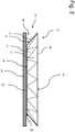
- the plurality of triangular beveled surfaces 7 arranged in the edge region 11 can also be clearly seen in this view.
- the bevel surfaces 7 completely surround a main surface 13 of the plate underside 4.
- Adjacent to the underside of the plate 4, the touch input device 1 has a touch sensor surface 5 which extends in the form of a plate along the entire underside 4 of the plate.
- a gap 14 is formed between the main surface 13 and the touch sensor surface 5, so that there is no direct contact between the touch sensor surface 5 and the cover plate 2.
- FIG. 3 is a schematic of a filler body 9 of the preferred embodiment of the touch input device 1 according to the invention Fig. 1 shown in a side view.
- the filler body 9 is formed from a preferably homogeneous filler material.
- the filler body has an annular edge 15 with a triangular cross-sectional area and a disk area 16. Between the edge 15 and the Disc area 16 has a recess 10 for receiving the cover plate 2.
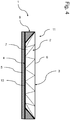
- Fig. 4 is schematically the touch input device 1 from Figure 1 shown in a side view.
- the filling body 9 is in the gap 14 (cf. Fig. 2 ) as well as in the free space 8 (cf. Fig. 2 ) arranged between the plate underside 4 and the touch sensor surface 5.
- the touch input device 1 use of the operating surface 6 extending over the entire top side 3 of the plate is possible due to the permittivity of the filler material, which corresponds or essentially corresponds to the permittivity of the cover plate material, without complex compensation by a computing unit.
Landscapes
- Engineering & Computer Science (AREA)
- General Engineering & Computer Science (AREA)
- Theoretical Computer Science (AREA)
- Human Computer Interaction (AREA)
- Physics & Mathematics (AREA)
- General Physics & Mathematics (AREA)
- Chemical & Material Sciences (AREA)
- Combustion & Propulsion (AREA)
- Transportation (AREA)
- Mechanical Engineering (AREA)
- Switches That Are Operated By Magnetic Or Electric Fields (AREA)
- Position Input By Displaying (AREA)
Description
- Die vorliegende Erfindung eine Touch-Eingabevorrichtung für ein Kraftfahrzeug zum Bedienen eines Systems, insbesondere eines elektronischen Systems, eines Kraftfahrzeugs. Ferner betrifft die Erfindung ein elektronisches System für ein Kraftfahrzeug sowie ein Kraftfahrzeug.
- Es ist eine Vielzahl unterschiedlicher Touch-Eingabevorrichtungen, wie z.B. Touchpads von Notebooks oder Touchscreens von Smartphones oder dergleichen, bekannt. Eine Touch-Eingabevorrichtung weist eine berührungs- bzw. druckempfindliche Bedienfläche auf und ist ausgebildet, eine Position auf der Bedienfläche, die von außen kontaktiert bzw. auf die von außen ein Druck ausgeübt wird, zu ermitteln. Somit ist beispielsweise eine Bewegungsbahn eines auf der Bedienfläche abgleitenden Fingers eines Bedieners bestimmbar. Moderne Touch-Eingabevorrichtungen sind ausgebildet, neben der Ermittlung der Position der Berührung bzw. des Druckes auch eine Stärke des Drucks zu ermitteln. Mittels derartiger Touch-Eingabevorrichtungen sind auch hochkomplexe Steuerbefehle an ein System, insbesondere einem elektronischen System eines Kraftfahrzeugs, wie z.B. einem Navigationssystem, einem Entertainmentsystem, einem Kommunikationssystem, einem Fahrzeugparameterüberwachungssystem oder dergleichen übertragbar.
- Herkömmliche Touch-Eingabevorrichtungen weisen eine Touchsensorfläche sowie eine die Touchsensorfläche schützende Deckplatte auf, wobei die Bedienfläche auf einer der Touchsensorfläche abgewandten Plattenoberseite der Deckplatte ausgebildet ist. Bekannte Touchsensorflächen weisen ein Elektrodengitter auf und sind zum Ermitteln einer elektrischen Kapazität zwischen den Elektroden ausgebildet. Externe Störfaktoren, wie z.B. ein Finger eines Bedieners der Touch-Eingabevorrichtung, der auf die Bedienfläche geführt wird, bewirken aufgrund einer von Luft stark abweichenden elektrischen Permittivität eine Veränderung der elektrischen Kapazität zwischen Elektroden. Diese Veränderung der elektrischen Kapazität ist von der Touch-Eingabevorrichtung ermittelbar und auf diese Weise die Position und ggf. die Höhe des auf die Bedienfläche ausgeübten Druck bestimmbar. Aus den Druckschriften
US 2007/0144795 A1 undUS 2009/0033636 A1 sind verschiedene Touch-Eingabevorrichtungen bekannt. - Um eine hohe Genauigkeit der Position zu ermöglichen, ist die Deckplatte möglichst flächig sowie spaltfrei an der Touchsensorfläche angeordnet. Ein Luftspalt in einem Bereich zwischen der Deckplatte und der Touchsensorfläche würde in diesem Bereich zu einer von den übrigen Bereichen abweichenden Veränderung der elektrischen Kapazität durch Einwirkung von außen führen. Dies macht eine sehr aufwendige Kompensation der von der Touchsensorfläche ermittelten Veränderung der elektrischen Kapazität durch eine Rechnereinheit erforderlich und kann insbesondere bei einer leistungsschwachen Rechnereinheit zu einer ungewollten Verzögerung einer Eingabe des Bedieners führen. Die Verwendung besonders leistungsstarker Recheneinheiten hat den Nachteil hoher Teilekosten sowie eines hohen Energieverbrauchs im Betrieb der Touch-Eingabevorrichtung.
- Es ist daher Aufgabe der vorliegenden Erfindung, die voranstehend beschriebenen Nachteile bei einer Touch-Eingabevorrichtung mit einer Abschrägfläche, einem elektronischen System für ein Kraftfahrzeug mit einer derartigen Touch-Eingabevorrichtung sowie einem Kraftfahrzeug mit einem derartigen System zu beheben oder zumindest teilweise zu beheben. Insbesondere ist es Aufgabe der vorliegenden Erfindung eine Touch-Eingabevorrichtung zum Bedienen eines Systems eines Kraftfahrzeugs, ein elektronisches System für ein Kraftfahrzeug sowie ein Kraftfahrzeug zu schaffen, die auf einer einfache und kostengünstige Art und Weise eine Verzögerung einer Eingabe eines Benutzers in Bereichen der Abschrägfläche vermeiden und eine geringere Kompensation der von der Touchsensorfläche ermittelten Veränderung der elektrischen Kapazität erfordern.
- Voranstehende Aufgabe wird durch eine Touch-Eingabevorrichtung mit den Merkmalen des Anspruchs 1, durch ein elektronisches System mit den Merkmalen des Anspruchs 11 sowie durch ein Kraftfahrzeug mit den Merkmalen des Anspruchs 12 gelöst. Weitere Merkmale und Details der Erfindung ergeben sich aus den Unteransprüchen, der Beschreibung und den Zeichnungen. Dabei gelten Merkmale und Details, die im Zusammenhang mit der Touch-Eingabevorrichtung beschrieben sind, selbstverständlich auch im Zusammenhang mit dem erfindungsgemäßen elektronischen System sowie dem erfindungsgemäßen Kraftfahrzeug und jeweils umgekehrt, so dass bezüglich der Offenbarung zu den einzelnen Erfindungsaspekten stets wechselseitig Bezug genommen wird beziehungsweise werden kann.
- Gemäß dem ersten Aspekt der Erfindung wird die Aufgabe durch eine Touch-Eingabevorrichtung zum Bedienen eines Systems eines Kraftfahrzeugs gelöst. Die Touch-Eingabevorrichtung weist eine Deckplatte aus einem Deckplattenmaterial und eine Touchsensorfläche auf. Die Deckplatte weist eine Plattenoberseite mit einer Bedienfläche und eine Plattenunterseite auf, wobei die Plattenunterseite der Deckplatte der Touchsensorfläche zugewandt ist. Erfindungsgemäß weist die Plattenunterseite mindestens eine Abschrägfläche auf, die schräg zur Touchsensorfläche angeordnet ist, wobei zwischen der Plattenunterseite und der Touchsensorfläche ein Freiraum ausgebildet ist. Die Bedienfläche überragt den Freiraum zumindest teilweise. In dem Freiraum ist ein Füllkörper aus mindestens einem Füllmaterial angeordnet, wobei das mindestens eine Füllmaterial eine Permittivität für elektrische Felder aufweist, die größer als eine Permittivität von Luft ist. Vorzugsweise ist die Permittivität des Füllmaterials näher an einer Permittivität des Deckplattenmaterials als an der Permittivität der Luft.
- Die Deckplatte weist ein Deckplattenmaterial auf und ist im Wesentlichen plattenförmig ausgebildet. Die Deckplatte weist eine Plattenoberseite und eine von der Plattenoberseite abgewandte Plattenunterseite auf, wobei vorzugsweise in einem Bereich die Plattenoberseite parallel zur Plattenunterseite angeordnet ist. Auf der Plattenoberseite ist eine Bedienfläche ausgebildet, über die Benutzereingaben an die Touch-Eingabevorrichtung übermittelbar sind. Vorzugsweise ist die Plattenoberseite vollständig oder zumindest im Wesentlichen vollständig als Bedienfläche ausgebildet.
- Erfindungsgemäß kann die Deckplatte zur Erfüllung einer Vielzahl unterschiedlicher Funktionen ausgebildet sein. Die Deckplatte deckt die Touchsensorfläche zum Bediener ab und schützt somit die Touchsensorfläche vor äußeren Einflüssen, wie z.B. Staub, Wasser oder dergleichen. Durch Ferner ist die Deckplatte ein optisches und/oder haptisches Gestaltungselement der Touch-Eingabevorrichtung. Durch eine Verblendung, Beschichtung, Beklebung oder dergleichen kann die Deckplatte eine Sicht auf die Touchsensorfläche vollständig oder zumindest teilweise verdecken. Eine möglichst glatte, insbesondere polierte, und/oder platte Oberfläche der Plattenoberseite ist besonders bevorzugt, um ein Abgleiten eines Fingers des Bedieners auf der Plattenoberseite zu verbessern. Die Plattenoberseite kann erfindungsgemäß auch eine Wölbung aufweisen bzw. gewölbt ausgebildet sein. Zusätzlich oder alternativ kann erfindungsgemäß vorgesehen sein, dass die Plattenoberseite lokale Erhebungen und/oder Vertiefungen und/oder Aufrauhungen aufweist, die auf Funktionen der Touch-Eingabevorrichtung hinweisen bzw. diese bezeichnen.
- Die Touchsensorfläche ist vorzugsweise als Touchsensorfläche einer herkömmlichen Touchsensorvorrichtung ausgebildet und weist vorzugsweise eine Vielzahl von Elektroden auf, die, insbesondere gleichmäßig bzw. im Wesentlichen gleichmäßig sowie abwechselnd, über die Touchsensorfläche verteilt sind. Die Touch-Eingabevorrichtung bzw. Touchsensorvorrichtung ist vorzugsweise zum Detektieren einer Veränderung einer elektrischen Kapazität zwischen den Elektroden ausgebildet.
- Erfindungsgemäß weist die Plattenunterseite mindestens eine Abschrägfläche auf. Unter einer Abschrägfläche wird im Sinne der Erfindung eine Fläche verstanden, die schräg zur Touchsensorfläche angeordnet ist. Die Abschrägfläche ist vorzugsweise schräg zu einer Hauptfläche der Plattenunterseite angeordnet, wobei die Hauptfläche als eine reale, platte Fläche oder als eine gemittelte Fläche aus mehreren schräg zueinander angeordneten Flächen der Plattenunterseite ausgebildet sein kann. Vorzugsweise ist die Abschrägfläche schräg zur Plattenoberseite angeordnet. Weiter bevorzugt ist die Hauptfläche parallel zur Plattenoberseite angeordnet. Die Abschrägfläche kann beispielsweise die Hauptfläche umgeben bzw. zumindest im Wesentlichen oder teilweise umgeben und ist vorzugsweise ringförmig ausgebildet. Alternativ kann die Hauptfläche von mehreren Abschrägflächen umgeben sein, die vorzugsweise ringförmig bzw. im Wesentlichen ringförmig miteinander angeordnet sind. Die Abschrägfläche kann mehrere Funktionen aufweisen, wie z.B. eine optische Verzierung der Touch-Eingabevorrichtung und/oder eine Kennzeichnung einer Funktion der Touch-Eingabevorrichtung, insbesondere eine pfeilartige Ausbildung. Es kann vorgesehen sein, dass die Abschrägfläche ausgebildet ist, eine besondere Brechung des Lichts zu bewirken, um beispielsweise Farb- bzw. Regenbogeneffekte zu erzeugen. Ferner kann erfindungsgemäß vorgesehen sein, dass die Touch-Eingabevorrichtung mindestens eine Leuchtvorrichtung aufweist, die zum Erzeugen eines Lichteffekts, insbesondere zur Kennzeichnung einer Funktion und/oder eines Zustands der Touch-Eingabevorrichtung, in Verbindung mit der mindestens einen Abschrägfläche ausgebildet ist.
- Durch die schräge Anordnung der Abschrägfläche zur Touchsensorfläche ist ein Freiraum zwischen der Abschrägfläche und der Touchsensorfläche ausgebildet. Die Bedienfläche überragt die Abschrägfläche. Um eine aufwendige Kompensation beim Benutzen der Bedienfläche in dem Bereich, der die Abschrägfläche überragt, zu vermeiden, ist in dem Freiraum ein Füllkörper aus mindestens einem Füllmaterial angeordnet. Der Füllkörper ist vorzugsweise flexibel ausgebildet, um eine Paarung zwischen Deckplatte und Füllkörper zu erleichtern bzw. zu verbessern. Ferner weist der Füllkörper vorzugsweise keine Kavitäten auf, um eine lokale Veränderung der Permittivität zu vermeiden. Es kann vorgesehen sein, dass der Füllkörper mittels eines Klebemittels oder mittels des Füllmaterials mit der Plattenunterseite und/oder Touchsensorfläche verklebt ist. Weiter kann vorgesehen sein, dass der Füllkörper unterschiedliche Dicken aufweist, insbesondere zum Ausfüllen von Zwischenräumen zwischen der Touchsensorfläche und der Deckplatte. Erfindungsgemäß weist das mindestens eine Füllmaterial eine Permittivität für elektrische Felder auf, die zumindest größer als eine Permittivität von Luft ist. Vorzugsweise entspricht die Permittivität des Füllmaterials einer Permittivität des Deckplattenmaterials zumindest im Wesentlichen. Ferner kann erfindungsgemäß vorgesehen sein, dass sich der Füllkörper auch in einem Bereich der Hauptfläche zwischen der Plattenunterseite und der Touchsensorfläche erstreckt.
- Das bedeutet, dass durch den Füllkörper eine Veränderung der Permittivität der Deckplatte im Bereich der Abschrägfläche kompensiert bzw. zumindest im Wesentlichen kompensiert wird, so dass keine aufwendige Kompensation mittels einer kostenintensiven Recheneinheit erforderlich ist. Dies hat den Vorteil, dass eine Eingabe durch einen Benutzer im Bereich der Abschrägfläche somit leicht möglich ist, ohne dass hierdurch eine übermäßige Eingabeverzögerung bewirkt wird. Ein weiterer Vorteil ist, dass eine aufwendige Recheneinheit nicht erforderlich ist und somit Herstellungskosten einsparbar sind. Die erfindungsgemäße Touch-Eingabevorrichtung ermöglicht somit eine Abschrägfläche im Bereich der Bedienfläche der Deckplatte ohne hierdurch entstehende Nachteile.
- Zudem weist der Füllkörper eine Ausnehmung auf, in der die Plattenunterseite aufgenommen ist. Dabei ist zumindest der Bereich der Plattenunterseite, der die mindestens eine Abschrägfläche aufweist und sich mit der Bedienfläche überschneidet, in der Ausnehmung angeordnet. Vorzugsweise ist auch die Hauptfläche der Plattenunterseite in der Ausnehmung angeordnet. Auf diese Weise ist die Deckplatte vorzugsweise formschlüssig von dem Füllkörper aufnehmbar, so dass bereits bei dem Zusammenbar der Touch-Eingabevorrichtung mit einfachen Mitteln sowie sicher die Deckplatte an dem Füllkörper bzw. der Füllkörper an der Deckplatte anordenbar ist. Es kann erfindungsgemäß vorgesehen sein, dass kein direkter Kontakt zwischen der Deckplatte und der Touchsensorfläche, sondern nur über den Füllkörper, besteht. Bei einem ringförmigen Füllkörper kann auch ein direkter Kontakt zwischen der Deckplatte und der Touchsensorfläche im Bereich der Hauptfläche bestehen. Ein ringförmiger Füllkörper weist vorzugsweise einen dreieckigen Querschnitt auf. Ein direkter Kontakt zwischen Deckplatte und der Touchsensorfläche im Bereich der Abschrägfläche ist erfindungsgemäß nicht vorgesehen sondern nur über den Füllkörper.
- Ferner ist die mindestens eine Abschrägfläche an einem Randbereich der Deckplatte angeordnet. Die Hauptfläche ist somit von der Abschrägfläche nach außen in zumindest eine Richtung begrenzt. Vorzugsweise umgibt die Abschrägfläche die Hauptfläche dabei im Wesentlichen oder komplett. Dabei ist die Abschrägfläche vorzugsweise derart ausgebildet, dass die Hauptfläche näher an der Touchsensorfläche angeordnet ist als die Abschrägfläche. Die Deckplatte weist somit eine Dicke auf, die sich in einem Randbereich durch die Abschrägfläche radial nach außen verjüngt.
- Die Plattenoberseite ist plan ausgebildet. Alternativ oder zusätzlich kann die Plattenoberseite zumindest teilweise auch konvex und/oder konkav ausgebildet sein. Eine derartig geformte Deckplatte hat den Vorteil, dass hiermit eine Vielzahl von Eingabebefehlen leicht möglich ist.
- Gemäß einer bevorzugten Weiterentwicklung der Erfindung kann bei einer Touch-Eingabevorrichtung vorgesehen sein, dass der Füllkörper die Plattenunterseite und die Touchsensorfläche flächig kontaktiert. Unter einem flächigen Kontaktieren wird im Sinne der Erfindung ein durchgängiges bzw. im Wesentlichen durchgängiges Kontaktieren verstanden, so dass keine bzw. im Wesentlichen keine Spalte zwischen Füllkörper, Plattenunterseite und Touchsensorfläche ausgebildet sind. Das Kontaktieren erfolgt somit über eine gemeinsame Kontaktfläche. Durch ein flächiges Kontaktieren wird der Freiraum durch den Füllkörper, zumindest im Bereich der Bedienfläche, komplett bzw. im Wesentlichen komplett ausgefüllt, so dass eine Permittivität der Paarung aus Deckplatte und Füllkörper zumindest über die Bedienfläche konstant bzw. im Wesentlichen konstant gehalten werden kann. Die Kontaktfläche kann beispielsweise kreisförmig oder ringförmig ausgebildet sein.
- Es ist erfindungsgemäß bevorzugt, dass der Füllkörper eine Füllkörperform aufweist, die komplementär zu einer Freiraumform des Freiraums ausgebildet ist. Hierdurch wird ein flächiges Kontaktieren von Füllkörper und Deckplatte verbessert. Eine komplementäre Form hat den Vorteil, dass ein möglichst großflächiges Kontaktieren von Deckplatte und Füllkörper möglich ist. Durch ein elastisches Füllkörpermaterial ist ein derartiges Kontaktieren weiter verbesserbar.
- Vorzugsweise ist der Füllkörper zumindest teilweise als Spritzgussteil oder 3D-Druckteil ausgebildet. Alternativ oder zusätzlich ist es bevorzugt, dass das mindestens eine Füllmaterial gießfähig ausgebildet ist. Demnach ist der Füllkörper beispielsweise vor dem Einsetzen in den Freiraum herstellbar oder alternativ als fließfähiges Füllmaterial in den Freiraum einbringbar, um im Freiraum auszuhärten. Ein derartiger Füllkörper ist leicht sowie mit einfachen Mitteln und kostengünstig herstellbar und optimal an eine Form des Freiraums anpassbar.
- Weiter bevorzugt ist das mindestens eine Füllmaterial ein Polyamid oder weist zumindest ein Polyamid auf. Polyamid ist gut sowie kostengünstig verfügbar und leicht verarbeitbar. Insbesondere für einen Spritzgießprozess ist Polyamid aufgrund einer leichten Aufschmelzbarkeit gut geeignet.
- Es kann erfindungsgemäß vorgesehen sein, dass das mindestens eine Füllmaterial aus einem Gießharz gebildet ist oder zumindest ein Gießharz und/oder einen Klebstoff aufweist. Ein derartiges Füllmaterial ist in fließfähiger Form zur Erzeugung des Füllkörpers in den Freiraum einbringbar und kann sich gut im Freiraum verteilen. Anschließend ist das Füllmaterial durch Abkühlung und/oder durch Zusatz eines Aushärtmittels zu dem Füllkörper aushärtbar. Auf derartigem Gießharz basierende Herstellungsverfahren zur Herstellung des Füllkörpers sind verhältnismäßig kostengünstig und leicht sowie mit einfachen Mitteln durchführbar.
- In einer vorteilhaften Ausgestaltung der Erfindung weist die Plattenunterseite eine Mehrzahl von Abschrägflächen auf, die in Form eines Facettenschliffs an der Plattenunterseite angeordnet sind. Vorzugsweise sind die Abschrägflächen dreieckig ausgebildet. Mittels einer derartigen Anordnung von Abschrägflächen ist eine Vielzahl unterschiedlicher optischer Effekte erzielbar. So kann beispielsweise eine pfeilartige Ausbildung der Abschrägflächen eine Bedienfunktion bzw. -richtung der Touch-Eingabevorrichtung indizieren.
- Vorzugsweise ist das Deckplattenmaterial Glas oder weist zumindest Glas auf. Dabei ist die Deckplatte vorzugsweise durchsichtig oder zumindest lichtdurchlässig. Es kann vorgesehen sein, dass ein die Touchsensorfläche und/oder den Füllkörper kontaktierender Bereich der Plattenunterseite eine Beschichtung aufweist. Diese Beschichtung ist vorzugsweise nicht durchsichtig und/oder lichtundurchlässig und/oder verspiegelt. Die Beschichtung ist vorzugsweise als Lack und/oder Folie ausgebildet und weiter bevorzugt mit der Deckplatte verklebt oder stoffschlüssig verbunden. Somit ist die Touchsensorfläche mit einfachen Mitteln sowie kostengünstig kaschierbar. Ein derartiges, Glas aufweisendes Deckplattenmaterial ist leicht sowie mit einfachen Mitteln und kostengünstig herstellbar und für spezielle Lichteffekte, insbesondere Lichtbrechungen, besonders geeignet.
- Es ist erfindungsgemäß bevorzugt, dass die Permittivität des mindestens einen Füllmaterials maximal um 30% von der Permittivität des Deckplattenmaterials abweicht. Weiter bevorzugt weicht die Permittivität maximal um 15% ab. Erfindungsgemäß ist es besonders bevorzugt, wenn die Permittivität des mindestens einen Füllmaterials maximal um 5% von der Permittivität des Deckplattenmaterials abweicht. Eine möglichst geringe Abweichung der Permittivität hat den Vorteil, dass bei einer Bedienung der Bedienfläche im Bereich der Abschrägfläche keine oder nur eine sehr geringe Kompensation der ermittelten Veränderung der elektrischen Kapazität erforderlich ist. Je mehr die Permittivität des mindestens einen Füllmaterials der Permittivität des Deckplattenmaterials entspricht, desto geringer ist die erforderliche Kompensation und somit der erforderliche Rechenaufwand. Somit sind Kosten für eine aufwendige Recheneinheit reduzierbar bzw. einsparbar.
- Es kann erfindungsgemäß vorgesehen sein, dass die Deckplatte eine Gravur und/oder einen Aufdruck aufweist. Die Gravur und/oder der Aufdruck können dabei in Abhängigkeit des Deckplattenmaterials auf der Plattenoberseite und/oder bei durchsichtigem Deckplattenmaterial auf der Plattenunterseite angeordnet sein. Dies hat den Vorteil, dass besondere Funktionen der Touch-Eingabevorrichtung für den Benutzer erkenntlich sind und eine Bedienung somit erleichtert wird.
Gemäß einem zweiten Aspekt der Erfindung wird die Aufgabe durch ein elektronisches System für ein Kraftfahrzeug gelöst. Das elektronische System weist mindestens eine Eingabevorrichtung auf, wobei die mindestens eine Eingabevorrichtung als erfindungsgemäße Touch-Eingabevorrichtung ausgebildet ist. Das elektronische System weist dieselben Vorteile auf, wie bereits voranstehend bezüglich der erfindungsgemäßen Touch-Eingabevorrichtung beschrieben sind. Demnach hat das elektronische System den Vorteil, dass die Deckplatte der Touch-Eingabevorrichtung des elektronischen Systems mindestens eine Abschrägfläche aufweist, wobei eine Eingabe durch einen Benutzer im Bereich der Abschrägfläche somit leicht möglich ist, ohne dass hierdurch eine übermäßige Eingabeverzögerung bewirkt wird. Ein weiterer Vorteil ist, dass das elektronische System keine aufwendige Recheneinheit benötigt und somit Herstellungskosten einsparbar sind. Das erfindungsgemäße elektronische System weist demnach auf vorteilhafte Weise eine Touch-Eingabevorrichtung mit einer Abschrägfläche im Bereich der Bedienfläche der Deckplatte auf, ohne dass hierdurch Nachteile bei der Bedienung entstehen. - Gemäß einem dritten Aspekt der Erfindung wird die Aufgabe durch ein Kraftfahrzeug mit mindestens einem erfindungsgemäßen elektronischen System gelöst. Das Kraftfahrzeug weist dieselben Vorteile auf, wie bereits voranstehend bezüglich der erfindungsgemäßen Touch-Eingabevorrichtung sowie des elektronischen Systems beschrieben sind. Demnach hat das Kraftfahrzeug den Vorteil, dass die Deckplatte der Touch-Eingabevorrichtung des elektronischen Systems des Kraftfahrzeugs mindestens eine Abschrägfläche aufweist, wobei eine Eingabe durch einen Benutzer im Bereich der Abschrägfläche leicht möglich ist, ohne dass hierdurch eine übermäßige Eingabeverzögerung bewirkt wird. Ein weiterer Vorteil ist, dass das elektronische System keine aufwendige Recheneinheit benötigt und somit Herstellungskosten einsparbar sind. Das erfindungsgemäße Kraftfahrzeug weist demnach auf vorteilhafte Weise ein elektronisches System mit einer Touch-Eingabevorrichtung mit einer Abschrägfläche im Bereich der Bedienfläche der Deckplatte auf, ohne dass hierdurch Nachteile bei der Bedienung entstehen.
- Eine erfindungsgemäße Touch-Eingabevorrichtung zum Bedienen eines Systems eines Kraftfahrzeugs wird nachfolgend anhand von Zeichnungen näher erläutert. Es zeigen jeweils schematisch:
-
Figur 1 in einer Draufsicht eine bevorzugte Ausführungsform einer erfindungsgemäßen Touch-Eingabevorrichtung, -
Figur 2 in einer Seitenansicht die Touch-Eingabevorrichtung ohne Füllkörper ausFigur 1 , -
Figur 3 in einer Seitenansicht den Füllkörper ausFigur 1 , und -
Figur 4 in einer Seitenansicht die Touch-Eingabevorrichtung ausFigur 1 . - Elemente mit gleicher Funktion und Wirkungsweise sind in den
Fig. 1 bis 4 jeweils mit denselben Bezugszeichen versehen. - In
Fig. 1 ist schematisch eine bevorzugte Ausführungsform einer erfindungsgemäßen Touch-Eingabevorrichtung 1 in einer Draufsicht dargestellt. Die Touch-Eingabevorrichtung 1 weist eine Deckplatte 2 mit einer kreisförmigen Plattenoberseite 3 auf. In einem zentralen Bereich weist die Plattenoberseite 3 mehrere Gravuren 12 auf, die beispielsweise unterschiedliche Funktionen bzw. Eingabeoptionen der Touch-Eingabevorrichtung 1 bezeichnen. In diesem Ausführungsbeispiel ist die Deckplatte 2 aus einem durchsichtigen Deckplattenwerkstoff, wie z.B. Glas, gebildet. Somit sind in einem Randbereich 11 auf einer Plattenunterseite 4 (vgl.Fig. 2 ) der Deckplatte 2 ausgebildete, dreieckige Abschrägflächen 7 sowie eine von den Abschrägflächen 7 umgebene Hauptfläche 13 der Plattenunterseite 4 erkennbar. Eine Bedienfläche 6 erstreckt sich über die komplette Plattenoberseite 3 und demnach über den Randbereich 11 und die Hauptfläche 13. - Wie aus
Fig. 2 besser ersichtlich, weist die Deckplatte 2 eine Plattenunterseite 4 auf, die sich entlang der kompletten Plattenoberseite 3 erstreckt. Die im Randbereich 11 angeordnete Mehrzahl dreieckiger Abschrägflächen 7 ist ebenfalls in dieser Ansicht gut erkennbar. Die Abschrägflächen 7 umgeben eine Hauptfläche 13 der Plattenunterseite 4 vollumfänglich. Der Plattenunterseite 4 benachbart weist die Touch-Eingabevorrichtung 1 eine Touchsensorfläche 5 auf, die sich entlang der kompletten Plattenunterseite 4 plattenförmig erstreckt. In diesem Ausführungsbeispiel ist zwischen der Hauptfläche 13 und der Touchsensorfläche 5 ein Spalt 14 ausgebildet, so dass kein direkter Kontakt zwischen der Touchsensorfläche 5 und der Deckplatte 2 besteht. - In
Fig. 3 ist schematisch ein Füllkörper 9 der bevorzugten Ausführungsform der erfindungsgemäßen Touch-Eingabevorrichtung 1 ausFig. 1 in einer Seitenansicht dargestellt. Der Füllkörper 9 ist aus einem vorzugsweise homogenen Füllmaterial gebildet. Der Füllkörper weist einen ringförmigen Rand 15 mit einer dreieckigen Querschnittsfläche sowie einen Scheibenbereich 16 auf. Zwischen dem Rand 15 und dem Scheibenbereich 16 ist eine Ausnehmung 10 zur Aufnahme der Deckplatte 2 ausgebildet. - In
Fig. 4 ist schematisch die Touch-Eingabevorrichtung 1 ausFigur 1 in einer Seitenansicht abgebildet. Der Füllkörper 9 ist in dem Spalt 14 (vgl.Fig. 2 )sowie in dem Freiraum 8 (vgl.Fig. 2 ) zwischen der Plattenunterseite 4 und der Touchsensorfläche 5 angeordnet. Bei der erfindungsgemäßen Touch-Eingabevorrichtung 1 ist eine Benutzung der sich über die komplette Plattenoberseite 3 erstreckenden Bedienfläche 6 aufgrund der Permittivität des Füllmaterials, die der Permittivität des Deckplattenmaterials entspricht bzw. im Wesentlichen entspricht, ohne eine aufwendige Kompensation durch eine Recheneinheit möglich. -
- 1
- Touch-Eingabevorrichtung
- 2
- Deckplatte
- 3
- Plattenoberseite
- 4
- Plattenunterseite
- 5
- Touchsensorfläche
- 6
- Bedienfläche
- 7
- Abschrägfläche
- 8
- Freiraum
- 9
- Füllkörper
- 10
- Ausnehmung
- 11
- Randbereich
- 12
- Gravur
- 13
- Hauptfläche
- 14
- Spalt
- 15
- Rand
- 16
- Scheibenbereich
Claims (12)
- Touch-Eingabevorrichtung (1) zum Bedienen eines Systems eines Kraftfahrzeugs, aufweisend eine Deckplatte (2) aus einem Deckplattenmaterial mit einer Plattenoberseite (3) und einer Plattenunterseite (4) und weiter aufweisend eine Touchsensorfläche (5), wobei die Plattenoberseite (3) eine Bedienfläche (6) aufweist, und wobei die Plattenunterseite (4) der Deckplatte (2) der Touchsensorfläche (5) zugewandt ist, wobei die Plattenunterseite (4) mindestens eine Abschrägfläche (7) aufweist, die schräg zur Touchsensorfläche (5) angeordnet ist, wobei zwischen der Plattenunterseite (4) und der Touchsensorfläche (5) ein Freiraum (8) ausgebildet ist, wobei die Bedienfläche (6) den Freiraum (8) zumindest teilweise überragt, wobei ein Füllkörper (9) aus mindestens einem Füllmaterial in dem Freiraum (8) angeordnet ist, und wobei das mindestens eine Füllmaterial eine Permittivität für elektrische Felder aufweist, die größer als eine Permittivität von Luft ist, wobei die mindestens eine Abschrägfläche (7) an einem Randbereich (11) der Deckplatte (2) angeordnet ist, dadurch gekennzeichnet, dass der Füllkörper (9) eine Ausnehmung (10) aufweist, in der die Plattenunterseite (4) aufgenommen ist, und wobei die Plattenoberseite (3) plan ausgebildet ist.
- Touch-Eingabevorrichtung (1) nach Anspruch 1, wobei der Füllkörper (9) die Plattenunterseite (4) und die Touchsensorfläche (5) flächig kontaktiert.
- Touch-Eingabevorrichtung (1) nach Anspruch 1 oder 2, wobei der Füllkörper (9) eine Füllkörperform aufweist, die komplementär zu einer Freiraumform des Freiraums (8) ausgebildet ist.
- Touch-Eingabevorrichtung (1) nach wenigstens einem der vorangegangenen Ansprüche, wobei der Füllkörper (9) zumindest teilweise als Spritzgussteil oder 3D-Druckteil ausgebildet ist.
- Touch-Eingabevorrichtung (1) nach wenigstens einem der vorangegangenen Ansprüche, wobei das mindestens eine Füllmaterial ein Polyamid ist oder zumindest ein Polyamid aufweist.
- Touch-Eingabevorrichtung (1) nach wenigstens einem der vorangegangenen Ansprüche, wobei das mindestens eine Füllmaterial aus einem Gießharz gebildet ist oder zumindest ein Gießharz und/oder einen Klebstoff aufweist.
- Touch-Eingabevorrichtung (1) nach wenigstens einem der vorangegangenen Ansprüche, wobei die Plattenunterseite (4) eine Mehrzahl von Abschrägflächen (7) aufweist, die in Form eines Facettenschliffs an der Plattenunterseite (4) angeordnet sind.
- Touch-Eingabevorrichtung (1) nach wenigstens einem der vorangegangenen Ansprüche, wobei das Deckplattenmaterial Glas ist oder zumindest Glas aufweist.
- Touch-Eingabevorrichtung (1) nach wenigstens einem der vorangegangenen Ansprüche, wobei die Permittivität des mindestens einen Füllmaterials maximal um 30% von der Permittivität des Deckplattenmaterials abweicht.
- Touch-Eingabevorrichtung (1) nach wenigstens einem der vorangegangenen Ansprüche, wobei die Deckplatte (2) eine Gravur (12) und/oder einen Aufdruck aufweist.
- Elektronisches System für ein Kraftfahrzeug, aufweisend mindestens eine Eingabevorrichtung, wobei die mindestens eine Eingabevorrichtung als Touch-Eingabevorrichtung (1) nach einem Ansprüche 1 bis 10 ausgebildet ist.
- Kraftfahrzeug mit mindestens einem elektronischen System, wobei das mindestens eine elektronische System nach Anspruch 11 ausgebildet ist.
Applications Claiming Priority (2)
| Application Number | Priority Date | Filing Date | Title |
|---|---|---|---|
| DE102016213868.5A DE102016213868A1 (de) | 2016-07-28 | 2016-07-28 | Touch-Eingabevorrichtung und elektronisches System für ein Kraftfahrzeug sowie Kraftfahrzeug |
| PCT/EP2017/066539 WO2018019520A1 (de) | 2016-07-28 | 2017-07-04 | Touch-eingabevorrichtung und elektronisches system für ein kraftfahrzeug sowie kraftfahrzeug |
Publications (2)
| Publication Number | Publication Date |
|---|---|
| EP3491497A1 EP3491497A1 (de) | 2019-06-05 |
| EP3491497B1 true EP3491497B1 (de) | 2020-11-25 |
Family
ID=59296834
Family Applications (1)
| Application Number | Title | Priority Date | Filing Date |
|---|---|---|---|
| EP17736919.6A Active EP3491497B1 (de) | 2016-07-28 | 2017-07-04 | Touch-eingabevorrichtung und elektronisches system für ein kraftfahrzeug sowie kraftfahrzeug |
Country Status (5)
| Country | Link |
|---|---|
| US (1) | US11126309B2 (de) |
| EP (1) | EP3491497B1 (de) |
| CN (1) | CN109074181B (de) |
| DE (1) | DE102016213868A1 (de) |
| WO (1) | WO2018019520A1 (de) |
Families Citing this family (1)
| Publication number | Priority date | Publication date | Assignee | Title |
|---|---|---|---|---|
| DE102018211019B4 (de) * | 2018-07-04 | 2025-05-15 | Bayerische Motoren Werke Aktiengesellschaft | Bedieneinheit eines Fahrzeugs |
Family Cites Families (9)
| Publication number | Priority date | Publication date | Assignee | Title |
|---|---|---|---|---|
| US7683891B2 (en) * | 2005-12-22 | 2010-03-23 | Synaptics Incorporated | Equalizing reference surface capacitance with uneven thickness |
| JP4554651B2 (ja) * | 2007-08-01 | 2010-09-29 | ホシデン株式会社 | タッチパネル入力装置 |
| US20100302200A1 (en) * | 2009-05-29 | 2010-12-02 | Delphi Technologies, Inc. | Capacitive touch panel having a non-planar touch surface |
| CN104717590B (zh) * | 2010-12-27 | 2020-09-15 | 株式会社精好 | 移动电话系统 |
| DE102011077899A1 (de) * | 2011-06-21 | 2012-12-27 | BSH Bosch und Siemens Hausgeräte GmbH | Kapazitive Bedieneinrichtung für ein Haushaltsgerät und Haushaltsgerät |
| CN103793689B (zh) * | 2014-01-27 | 2017-06-06 | 南昌欧菲光科技有限公司 | 指纹识别传感器封装结构、电子设备及指纹识别传感器的制备方法 |
| TWI529582B (zh) * | 2014-06-18 | 2016-04-11 | 宸鴻科技(廈門)有限公司 | 具有指紋識別功能的觸控面板 |
| KR101866740B1 (ko) * | 2014-11-13 | 2018-06-15 | 현대자동차주식회사 | 터치 입력장치 및 이를 포함하는 차량 |
| KR20170058742A (ko) * | 2015-11-19 | 2017-05-29 | 현대자동차주식회사 | 터치 입력장치, 이를 포함하는 차량, 및 그 제조방법 |
-
2016
- 2016-07-28 DE DE102016213868.5A patent/DE102016213868A1/de active Pending
-
2017
- 2017-07-04 WO PCT/EP2017/066539 patent/WO2018019520A1/de not_active Ceased
- 2017-07-04 CN CN201780025969.6A patent/CN109074181B/zh active Active
- 2017-07-04 EP EP17736919.6A patent/EP3491497B1/de active Active
-
2019
- 2019-01-28 US US16/259,204 patent/US11126309B2/en active Active
Non-Patent Citations (1)
| Title |
|---|
| None * |
Also Published As
| Publication number | Publication date |
|---|---|
| DE102016213868A1 (de) | 2018-02-01 |
| CN109074181A (zh) | 2018-12-21 |
| US11126309B2 (en) | 2021-09-21 |
| US20190155447A1 (en) | 2019-05-23 |
| CN109074181B (zh) | 2022-02-08 |
| WO2018019520A1 (de) | 2018-02-01 |
| EP3491497A1 (de) | 2019-06-05 |
Similar Documents
| Publication | Publication Date | Title |
|---|---|---|
| DE102012020609B4 (de) | Bedienelement für einen Kraftwagen sowie Verfahren zum Herstellen eines Bedienelements | |
| EP3554883B1 (de) | Formteil und verfahren zum herstellen eines formteils | |
| EP2598975B1 (de) | Verfahren zur herstellung eines kapazitiven berührungssensors sowie kapazitiver berührungssensor | |
| DE60310757T2 (de) | Verfahren zur herstellung von einer polarisierten linse | |
| CN106339662A (zh) | 指纹辨识模块 | |
| DE102015114812A1 (de) | Berührvorrichtung | |
| DE102013221064A1 (de) | Abdeckung für einen Radarsensor für Kraftfahrzeuge | |
| DE102016226214A1 (de) | Formwerkzeug und Verfahren zum Verformen und Hinterspritzen einer biegbaren Platte | |
| DE102015101013A1 (de) | Formteil, insbesondere als Formteil ausgebildetes Dekorteil und/oder Verkleidungsteil für einen Fahrzeuginnenraum, und Verfahren zum Herstellen eines Formteils | |
| JP2015108793A (ja) | カバーガラスおよびカバーガラス付き表示装置 | |
| EP3491497B1 (de) | Touch-eingabevorrichtung und elektronisches system für ein kraftfahrzeug sowie kraftfahrzeug | |
| DE102016111190A1 (de) | Touchpanel und Herstellungsverfahren davon | |
| DE102015011413A1 (de) | Bedieneinrichtung eines Kraftfahrzeugs mit einem beleuchtbaren Symbol | |
| WO2014012761A1 (de) | Dachdeckel für ein fahrzeug und dazugehöriges verfahren zur herstellung | |
| DE202011105529U1 (de) | Lichtleiterstruktur mit Tastenfeldstruktur | |
| DE102011105190A1 (de) | Kunststoffteil | |
| US9616603B2 (en) | Floating core for glass insert molding method and apparatuses therefrom | |
| US20160274698A1 (en) | Sensor panel and method of manufacturing sensor panel | |
| DE202016005090U1 (de) | Elektronische Vorrichtung und Komponentenmodul | |
| EP2755808B1 (de) | Beheizbare blockstempel-vorrichtung | |
| DE202019101016U1 (de) | Schutzglas für Displays | |
| DE102019104469A1 (de) | Schutzglas für Displays | |
| KR101954244B1 (ko) | 곡면 형상의 표면에 대한 밀착성이 우수한 보호 필름 및 이를 포함하는 디스플레이 장치 | |
| DE102019110319A1 (de) | Bedieneinrichtung und Verfahren zum Herstellen einer Bedieneinrichtung | |
| WO2019023724A1 (de) | Industriebedienpanel |
Legal Events
| Date | Code | Title | Description |
|---|---|---|---|
| STAA | Information on the status of an ep patent application or granted ep patent |
Free format text: STATUS: UNKNOWN |
|
| STAA | Information on the status of an ep patent application or granted ep patent |
Free format text: STATUS: THE INTERNATIONAL PUBLICATION HAS BEEN MADE |
|
| PUAI | Public reference made under article 153(3) epc to a published international application that has entered the european phase |
Free format text: ORIGINAL CODE: 0009012 |
|
| STAA | Information on the status of an ep patent application or granted ep patent |
Free format text: STATUS: REQUEST FOR EXAMINATION WAS MADE |
|
| 17P | Request for examination filed |
Effective date: 20180926 |
|
| AK | Designated contracting states |
Kind code of ref document: A1 Designated state(s): AL AT BE BG CH CY CZ DE DK EE ES FI FR GB GR HR HU IE IS IT LI LT LU LV MC MK MT NL NO PL PT RO RS SE SI SK SM TR |
|
| AX | Request for extension of the european patent |
Extension state: BA ME |
|
| DAV | Request for validation of the european patent (deleted) | ||
| DAX | Request for extension of the european patent (deleted) | ||
| RIC1 | Information provided on ipc code assigned before grant |
Ipc: B60K 35/00 20060101ALI20200616BHEP Ipc: B32B 3/00 20060101ALI20200616BHEP Ipc: B60K 37/06 20060101ALI20200616BHEP Ipc: G06F 3/0354 20130101AFI20200616BHEP Ipc: G06F 3/044 20060101ALI20200616BHEP |
|
| GRAP | Despatch of communication of intention to grant a patent |
Free format text: ORIGINAL CODE: EPIDOSNIGR1 |
|
| STAA | Information on the status of an ep patent application or granted ep patent |
Free format text: STATUS: GRANT OF PATENT IS INTENDED |
|
| INTG | Intention to grant announced |
Effective date: 20200818 |
|
| GRAS | Grant fee paid |
Free format text: ORIGINAL CODE: EPIDOSNIGR3 |
|
| GRAA | (expected) grant |
Free format text: ORIGINAL CODE: 0009210 |
|
| STAA | Information on the status of an ep patent application or granted ep patent |
Free format text: STATUS: THE PATENT HAS BEEN GRANTED |
|
| AK | Designated contracting states |
Kind code of ref document: B1 Designated state(s): AL AT BE BG CH CY CZ DE DK EE ES FI FR GB GR HR HU IE IS IT LI LT LU LV MC MK MT NL NO PL PT RO RS SE SI SK SM TR |
|
| REG | Reference to a national code |
Ref country code: GB Ref legal event code: FG4D Free format text: NOT ENGLISH |
|
| REG | Reference to a national code |
Ref country code: CH Ref legal event code: EP |
|
| REG | Reference to a national code |
Ref country code: AT Ref legal event code: REF Ref document number: 1339052 Country of ref document: AT Kind code of ref document: T Effective date: 20201215 |
|
| REG | Reference to a national code |
Ref country code: DE Ref legal event code: R096 Ref document number: 502017008370 Country of ref document: DE |
|
| REG | Reference to a national code |
Ref country code: IE Ref legal event code: FG4D Free format text: LANGUAGE OF EP DOCUMENT: GERMAN |
|
| REG | Reference to a national code |
Ref country code: NL Ref legal event code: MP Effective date: 20201125 |
|
| PG25 | Lapsed in a contracting state [announced via postgrant information from national office to epo] |
Ref country code: PT Free format text: LAPSE BECAUSE OF FAILURE TO SUBMIT A TRANSLATION OF THE DESCRIPTION OR TO PAY THE FEE WITHIN THE PRESCRIBED TIME-LIMIT Effective date: 20210325 Ref country code: RS Free format text: LAPSE BECAUSE OF FAILURE TO SUBMIT A TRANSLATION OF THE DESCRIPTION OR TO PAY THE FEE WITHIN THE PRESCRIBED TIME-LIMIT Effective date: 20201125 Ref country code: NO Free format text: LAPSE BECAUSE OF FAILURE TO SUBMIT A TRANSLATION OF THE DESCRIPTION OR TO PAY THE FEE WITHIN THE PRESCRIBED TIME-LIMIT Effective date: 20210225 Ref country code: FI Free format text: LAPSE BECAUSE OF FAILURE TO SUBMIT A TRANSLATION OF THE DESCRIPTION OR TO PAY THE FEE WITHIN THE PRESCRIBED TIME-LIMIT Effective date: 20201125 Ref country code: GR Free format text: LAPSE BECAUSE OF FAILURE TO SUBMIT A TRANSLATION OF THE DESCRIPTION OR TO PAY THE FEE WITHIN THE PRESCRIBED TIME-LIMIT Effective date: 20210226 |
|
| PG25 | Lapsed in a contracting state [announced via postgrant information from national office to epo] |
Ref country code: LV Free format text: LAPSE BECAUSE OF FAILURE TO SUBMIT A TRANSLATION OF THE DESCRIPTION OR TO PAY THE FEE WITHIN THE PRESCRIBED TIME-LIMIT Effective date: 20201125 Ref country code: IS Free format text: LAPSE BECAUSE OF FAILURE TO SUBMIT A TRANSLATION OF THE DESCRIPTION OR TO PAY THE FEE WITHIN THE PRESCRIBED TIME-LIMIT Effective date: 20210325 Ref country code: PL Free format text: LAPSE BECAUSE OF FAILURE TO SUBMIT A TRANSLATION OF THE DESCRIPTION OR TO PAY THE FEE WITHIN THE PRESCRIBED TIME-LIMIT Effective date: 20201125 Ref country code: SE Free format text: LAPSE BECAUSE OF FAILURE TO SUBMIT A TRANSLATION OF THE DESCRIPTION OR TO PAY THE FEE WITHIN THE PRESCRIBED TIME-LIMIT Effective date: 20201125 Ref country code: BG Free format text: LAPSE BECAUSE OF FAILURE TO SUBMIT A TRANSLATION OF THE DESCRIPTION OR TO PAY THE FEE WITHIN THE PRESCRIBED TIME-LIMIT Effective date: 20210225 |
|
| REG | Reference to a national code |
Ref country code: LT Ref legal event code: MG9D |
|
| PG25 | Lapsed in a contracting state [announced via postgrant information from national office to epo] |
Ref country code: HR Free format text: LAPSE BECAUSE OF FAILURE TO SUBMIT A TRANSLATION OF THE DESCRIPTION OR TO PAY THE FEE WITHIN THE PRESCRIBED TIME-LIMIT Effective date: 20201125 |
|
| PG25 | Lapsed in a contracting state [announced via postgrant information from national office to epo] |
Ref country code: SM Free format text: LAPSE BECAUSE OF FAILURE TO SUBMIT A TRANSLATION OF THE DESCRIPTION OR TO PAY THE FEE WITHIN THE PRESCRIBED TIME-LIMIT Effective date: 20201125 Ref country code: CZ Free format text: LAPSE BECAUSE OF FAILURE TO SUBMIT A TRANSLATION OF THE DESCRIPTION OR TO PAY THE FEE WITHIN THE PRESCRIBED TIME-LIMIT Effective date: 20201125 Ref country code: EE Free format text: LAPSE BECAUSE OF FAILURE TO SUBMIT A TRANSLATION OF THE DESCRIPTION OR TO PAY THE FEE WITHIN THE PRESCRIBED TIME-LIMIT Effective date: 20201125 Ref country code: LT Free format text: LAPSE BECAUSE OF FAILURE TO SUBMIT A TRANSLATION OF THE DESCRIPTION OR TO PAY THE FEE WITHIN THE PRESCRIBED TIME-LIMIT Effective date: 20201125 Ref country code: SK Free format text: LAPSE BECAUSE OF FAILURE TO SUBMIT A TRANSLATION OF THE DESCRIPTION OR TO PAY THE FEE WITHIN THE PRESCRIBED TIME-LIMIT Effective date: 20201125 Ref country code: RO Free format text: LAPSE BECAUSE OF FAILURE TO SUBMIT A TRANSLATION OF THE DESCRIPTION OR TO PAY THE FEE WITHIN THE PRESCRIBED TIME-LIMIT Effective date: 20201125 |
|
| REG | Reference to a national code |
Ref country code: DE Ref legal event code: R097 Ref document number: 502017008370 Country of ref document: DE |
|
| PG25 | Lapsed in a contracting state [announced via postgrant information from national office to epo] |
Ref country code: DK Free format text: LAPSE BECAUSE OF FAILURE TO SUBMIT A TRANSLATION OF THE DESCRIPTION OR TO PAY THE FEE WITHIN THE PRESCRIBED TIME-LIMIT Effective date: 20201125 |
|
| PLBE | No opposition filed within time limit |
Free format text: ORIGINAL CODE: 0009261 |
|
| STAA | Information on the status of an ep patent application or granted ep patent |
Free format text: STATUS: NO OPPOSITION FILED WITHIN TIME LIMIT |
|
| PG25 | Lapsed in a contracting state [announced via postgrant information from national office to epo] |
Ref country code: IT Free format text: LAPSE BECAUSE OF FAILURE TO SUBMIT A TRANSLATION OF THE DESCRIPTION OR TO PAY THE FEE WITHIN THE PRESCRIBED TIME-LIMIT Effective date: 20201125 Ref country code: AL Free format text: LAPSE BECAUSE OF FAILURE TO SUBMIT A TRANSLATION OF THE DESCRIPTION OR TO PAY THE FEE WITHIN THE PRESCRIBED TIME-LIMIT Effective date: 20201125 Ref country code: NL Free format text: LAPSE BECAUSE OF FAILURE TO SUBMIT A TRANSLATION OF THE DESCRIPTION OR TO PAY THE FEE WITHIN THE PRESCRIBED TIME-LIMIT Effective date: 20201125 |
|
| 26N | No opposition filed |
Effective date: 20210826 |
|
| PG25 | Lapsed in a contracting state [announced via postgrant information from national office to epo] |
Ref country code: SI Free format text: LAPSE BECAUSE OF FAILURE TO SUBMIT A TRANSLATION OF THE DESCRIPTION OR TO PAY THE FEE WITHIN THE PRESCRIBED TIME-LIMIT Effective date: 20201125 |
|
| PG25 | Lapsed in a contracting state [announced via postgrant information from national office to epo] |
Ref country code: ES Free format text: LAPSE BECAUSE OF FAILURE TO SUBMIT A TRANSLATION OF THE DESCRIPTION OR TO PAY THE FEE WITHIN THE PRESCRIBED TIME-LIMIT Effective date: 20201125 |
|
| REG | Reference to a national code |
Ref country code: CH Ref legal event code: PL |
|
| PG25 | Lapsed in a contracting state [announced via postgrant information from national office to epo] |
Ref country code: MC Free format text: LAPSE BECAUSE OF FAILURE TO SUBMIT A TRANSLATION OF THE DESCRIPTION OR TO PAY THE FEE WITHIN THE PRESCRIBED TIME-LIMIT Effective date: 20201125 |
|
| REG | Reference to a national code |
Ref country code: BE Ref legal event code: MM Effective date: 20210731 |
|
| PG25 | Lapsed in a contracting state [announced via postgrant information from national office to epo] |
Ref country code: LI Free format text: LAPSE BECAUSE OF NON-PAYMENT OF DUE FEES Effective date: 20210731 Ref country code: CH Free format text: LAPSE BECAUSE OF NON-PAYMENT OF DUE FEES Effective date: 20210731 |
|
| PG25 | Lapsed in a contracting state [announced via postgrant information from national office to epo] |
Ref country code: IS Free format text: LAPSE BECAUSE OF FAILURE TO SUBMIT A TRANSLATION OF THE DESCRIPTION OR TO PAY THE FEE WITHIN THE PRESCRIBED TIME-LIMIT Effective date: 20210325 Ref country code: LU Free format text: LAPSE BECAUSE OF NON-PAYMENT OF DUE FEES Effective date: 20210704 |
|
| PG25 | Lapsed in a contracting state [announced via postgrant information from national office to epo] |
Ref country code: IE Free format text: LAPSE BECAUSE OF NON-PAYMENT OF DUE FEES Effective date: 20210704 Ref country code: BE Free format text: LAPSE BECAUSE OF NON-PAYMENT OF DUE FEES Effective date: 20210731 |
|
| P01 | Opt-out of the competence of the unified patent court (upc) registered |
Effective date: 20230503 |
|
| PG25 | Lapsed in a contracting state [announced via postgrant information from national office to epo] |
Ref country code: CY Free format text: LAPSE BECAUSE OF FAILURE TO SUBMIT A TRANSLATION OF THE DESCRIPTION OR TO PAY THE FEE WITHIN THE PRESCRIBED TIME-LIMIT Effective date: 20201125 |
|
| PG25 | Lapsed in a contracting state [announced via postgrant information from national office to epo] |
Ref country code: HU Free format text: LAPSE BECAUSE OF FAILURE TO SUBMIT A TRANSLATION OF THE DESCRIPTION OR TO PAY THE FEE WITHIN THE PRESCRIBED TIME-LIMIT; INVALID AB INITIO Effective date: 20170704 |
|
| REG | Reference to a national code |
Ref country code: AT Ref legal event code: MM01 Ref document number: 1339052 Country of ref document: AT Kind code of ref document: T Effective date: 20220704 |
|
| PG25 | Lapsed in a contracting state [announced via postgrant information from national office to epo] |
Ref country code: AT Free format text: LAPSE BECAUSE OF NON-PAYMENT OF DUE FEES Effective date: 20220704 |
|
| PG25 | Lapsed in a contracting state [announced via postgrant information from national office to epo] |
Ref country code: MK Free format text: LAPSE BECAUSE OF FAILURE TO SUBMIT A TRANSLATION OF THE DESCRIPTION OR TO PAY THE FEE WITHIN THE PRESCRIBED TIME-LIMIT Effective date: 20201125 |
|
| PG25 | Lapsed in a contracting state [announced via postgrant information from national office to epo] |
Ref country code: TR Free format text: LAPSE BECAUSE OF FAILURE TO SUBMIT A TRANSLATION OF THE DESCRIPTION OR TO PAY THE FEE WITHIN THE PRESCRIBED TIME-LIMIT Effective date: 20201125 |
|
| PG25 | Lapsed in a contracting state [announced via postgrant information from national office to epo] |
Ref country code: MT Free format text: LAPSE BECAUSE OF FAILURE TO SUBMIT A TRANSLATION OF THE DESCRIPTION OR TO PAY THE FEE WITHIN THE PRESCRIBED TIME-LIMIT Effective date: 20201125 |
|
| PGFP | Annual fee paid to national office [announced via postgrant information from national office to epo] |
Ref country code: DE Payment date: 20250702 Year of fee payment: 9 |
|
| PGFP | Annual fee paid to national office [announced via postgrant information from national office to epo] |
Ref country code: GB Payment date: 20250724 Year of fee payment: 9 |
|
| PGFP | Annual fee paid to national office [announced via postgrant information from national office to epo] |
Ref country code: FR Payment date: 20250723 Year of fee payment: 9 |