EP3491228B1 - Panneau d'atténuation acoustique pour ensemble propulsif d'aéronef et ensemble propulsif comportant un tel panneau - Google Patents
Panneau d'atténuation acoustique pour ensemble propulsif d'aéronef et ensemble propulsif comportant un tel panneau Download PDFInfo
- Publication number
- EP3491228B1 EP3491228B1 EP17757802.8A EP17757802A EP3491228B1 EP 3491228 B1 EP3491228 B1 EP 3491228B1 EP 17757802 A EP17757802 A EP 17757802A EP 3491228 B1 EP3491228 B1 EP 3491228B1
- Authority
- EP
- European Patent Office
- Prior art keywords
- acoustic
- panel
- propulsion unit
- fan
- skin
- Prior art date
- Legal status (The legal status is an assumption and is not a legal conclusion. Google has not performed a legal analysis and makes no representation as to the accuracy of the status listed.)
- Active
Links
Images


Classifications
-
- B—PERFORMING OPERATIONS; TRANSPORTING
- B64—AIRCRAFT; AVIATION; COSMONAUTICS
- B64D—EQUIPMENT FOR FITTING IN OR TO AIRCRAFT; FLIGHT SUITS; PARACHUTES; ARRANGEMENT OR MOUNTING OF POWER PLANTS OR PROPULSION TRANSMISSIONS IN AIRCRAFT
- B64D33/00—Arrangement in aircraft of power plant parts or auxiliaries not otherwise provided for
- B64D33/02—Arrangement in aircraft of power plant parts or auxiliaries not otherwise provided for of combustion air intakes
-
- B—PERFORMING OPERATIONS; TRANSPORTING
- B64—AIRCRAFT; AVIATION; COSMONAUTICS
- B64D—EQUIPMENT FOR FITTING IN OR TO AIRCRAFT; FLIGHT SUITS; PARACHUTES; ARRANGEMENT OR MOUNTING OF POWER PLANTS OR PROPULSION TRANSMISSIONS IN AIRCRAFT
- B64D29/00—Power-plant nacelles, fairings or cowlings
-
- B—PERFORMING OPERATIONS; TRANSPORTING
- B64—AIRCRAFT; AVIATION; COSMONAUTICS
- B64D—EQUIPMENT FOR FITTING IN OR TO AIRCRAFT; FLIGHT SUITS; PARACHUTES; ARRANGEMENT OR MOUNTING OF POWER PLANTS OR PROPULSION TRANSMISSIONS IN AIRCRAFT
- B64D33/00—Arrangement in aircraft of power plant parts or auxiliaries not otherwise provided for
- B64D33/04—Arrangement in aircraft of power plant parts or auxiliaries not otherwise provided for of exhaust outlets or jet pipes
- B64D33/06—Silencing exhaust or propulsion jets
-
- F—MECHANICAL ENGINEERING; LIGHTING; HEATING; WEAPONS; BLASTING
- F02—COMBUSTION ENGINES; HOT-GAS OR COMBUSTION-PRODUCT ENGINE PLANTS
- F02C—GAS-TURBINE PLANTS; AIR INTAKES FOR JET-PROPULSION PLANTS; CONTROLLING FUEL SUPPLY IN AIR-BREATHING JET-PROPULSION PLANTS
- F02C7/00—Features, components parts, details or accessories, not provided for in, or of interest apart form groups F02C1/00 - F02C6/00; Air intakes for jet-propulsion plants
- F02C7/04—Air intakes for gas-turbine plants or jet-propulsion plants
- F02C7/045—Air intakes for gas-turbine plants or jet-propulsion plants having provisions for noise suppression
-
- F—MECHANICAL ENGINEERING; LIGHTING; HEATING; WEAPONS; BLASTING
- F02—COMBUSTION ENGINES; HOT-GAS OR COMBUSTION-PRODUCT ENGINE PLANTS
- F02C—GAS-TURBINE PLANTS; AIR INTAKES FOR JET-PROPULSION PLANTS; CONTROLLING FUEL SUPPLY IN AIR-BREATHING JET-PROPULSION PLANTS
- F02C7/00—Features, components parts, details or accessories, not provided for in, or of interest apart form groups F02C1/00 - F02C6/00; Air intakes for jet-propulsion plants
- F02C7/24—Heat or noise insulation
-
- F—MECHANICAL ENGINEERING; LIGHTING; HEATING; WEAPONS; BLASTING
- F02—COMBUSTION ENGINES; HOT-GAS OR COMBUSTION-PRODUCT ENGINE PLANTS
- F02K—JET-PROPULSION PLANTS
- F02K1/00—Plants characterised by the form or arrangement of the jet pipe or nozzle; Jet pipes or nozzles peculiar thereto
- F02K1/78—Other construction of jet pipes
- F02K1/82—Jet pipe walls, e.g. liners
- F02K1/827—Sound absorbing structures or liners
-
- G—PHYSICS
- G10—MUSICAL INSTRUMENTS; ACOUSTICS
- G10K—SOUND-PRODUCING DEVICES; METHODS OR DEVICES FOR PROTECTING AGAINST, OR FOR DAMPING, NOISE OR OTHER ACOUSTIC WAVES IN GENERAL; ACOUSTICS NOT OTHERWISE PROVIDED FOR
- G10K11/00—Methods or devices for transmitting, conducting or directing sound in general; Methods or devices for protecting against, or for damping, noise or other acoustic waves in general
- G10K11/16—Methods or devices for protecting against, or for damping, noise or other acoustic waves in general
- G10K11/172—Methods or devices for protecting against, or for damping, noise or other acoustic waves in general using resonance effects
-
- B—PERFORMING OPERATIONS; TRANSPORTING
- B64—AIRCRAFT; AVIATION; COSMONAUTICS
- B64D—EQUIPMENT FOR FITTING IN OR TO AIRCRAFT; FLIGHT SUITS; PARACHUTES; ARRANGEMENT OR MOUNTING OF POWER PLANTS OR PROPULSION TRANSMISSIONS IN AIRCRAFT
- B64D33/00—Arrangement in aircraft of power plant parts or auxiliaries not otherwise provided for
- B64D33/02—Arrangement in aircraft of power plant parts or auxiliaries not otherwise provided for of combustion air intakes
- B64D2033/0206—Arrangement in aircraft of power plant parts or auxiliaries not otherwise provided for of combustion air intakes comprising noise reduction means, e.g. acoustic liners
-
- B—PERFORMING OPERATIONS; TRANSPORTING
- B64—AIRCRAFT; AVIATION; COSMONAUTICS
- B64D—EQUIPMENT FOR FITTING IN OR TO AIRCRAFT; FLIGHT SUITS; PARACHUTES; ARRANGEMENT OR MOUNTING OF POWER PLANTS OR PROPULSION TRANSMISSIONS IN AIRCRAFT
- B64D33/00—Arrangement in aircraft of power plant parts or auxiliaries not otherwise provided for
- B64D33/02—Arrangement in aircraft of power plant parts or auxiliaries not otherwise provided for of combustion air intakes
- B64D2033/0266—Arrangement in aircraft of power plant parts or auxiliaries not otherwise provided for of combustion air intakes specially adapted for particular type of power plants
- B64D2033/0286—Arrangement in aircraft of power plant parts or auxiliaries not otherwise provided for of combustion air intakes specially adapted for particular type of power plants for turbofan engines
-
- F—MECHANICAL ENGINEERING; LIGHTING; HEATING; WEAPONS; BLASTING
- F05—INDEXING SCHEMES RELATING TO ENGINES OR PUMPS IN VARIOUS SUBCLASSES OF CLASSES F01-F04
- F05D—INDEXING SCHEME FOR ASPECTS RELATING TO NON-POSITIVE-DISPLACEMENT MACHINES OR ENGINES, GAS-TURBINES OR JET-PROPULSION PLANTS
- F05D2240/00—Components
- F05D2240/10—Stators
- F05D2240/14—Casings or housings protecting or supporting assemblies within
-
- F—MECHANICAL ENGINEERING; LIGHTING; HEATING; WEAPONS; BLASTING
- F05—INDEXING SCHEMES RELATING TO ENGINES OR PUMPS IN VARIOUS SUBCLASSES OF CLASSES F01-F04
- F05D—INDEXING SCHEME FOR ASPECTS RELATING TO NON-POSITIVE-DISPLACEMENT MACHINES OR ENGINES, GAS-TURBINES OR JET-PROPULSION PLANTS
- F05D2250/00—Geometry
- F05D2250/20—Three-dimensional
- F05D2250/28—Three-dimensional patterned
- F05D2250/283—Three-dimensional patterned honeycomb
-
- F—MECHANICAL ENGINEERING; LIGHTING; HEATING; WEAPONS; BLASTING
- F05—INDEXING SCHEMES RELATING TO ENGINES OR PUMPS IN VARIOUS SUBCLASSES OF CLASSES F01-F04
- F05D—INDEXING SCHEME FOR ASPECTS RELATING TO NON-POSITIVE-DISPLACEMENT MACHINES OR ENGINES, GAS-TURBINES OR JET-PROPULSION PLANTS
- F05D2260/00—Function
- F05D2260/96—Preventing, counteracting or reducing vibration or noise
-
- F—MECHANICAL ENGINEERING; LIGHTING; HEATING; WEAPONS; BLASTING
- F05—INDEXING SCHEMES RELATING TO ENGINES OR PUMPS IN VARIOUS SUBCLASSES OF CLASSES F01-F04
- F05D—INDEXING SCHEME FOR ASPECTS RELATING TO NON-POSITIVE-DISPLACEMENT MACHINES OR ENGINES, GAS-TURBINES OR JET-PROPULSION PLANTS
- F05D2260/00—Function
- F05D2260/96—Preventing, counteracting or reducing vibration or noise
- F05D2260/963—Preventing, counteracting or reducing vibration or noise by Helmholtz resonators
-
- F—MECHANICAL ENGINEERING; LIGHTING; HEATING; WEAPONS; BLASTING
- F05—INDEXING SCHEMES RELATING TO ENGINES OR PUMPS IN VARIOUS SUBCLASSES OF CLASSES F01-F04
- F05D—INDEXING SCHEME FOR ASPECTS RELATING TO NON-POSITIVE-DISPLACEMENT MACHINES OR ENGINES, GAS-TURBINES OR JET-PROPULSION PLANTS
- F05D2300/00—Materials; Properties thereof
- F05D2300/60—Properties or characteristics given to material by treatment or manufacturing
- F05D2300/603—Composites; e.g. fibre-reinforced
-
- G—PHYSICS
- G10—MUSICAL INSTRUMENTS; ACOUSTICS
- G10K—SOUND-PRODUCING DEVICES; METHODS OR DEVICES FOR PROTECTING AGAINST, OR FOR DAMPING, NOISE OR OTHER ACOUSTIC WAVES IN GENERAL; ACOUSTICS NOT OTHERWISE PROVIDED FOR
- G10K11/00—Methods or devices for transmitting, conducting or directing sound in general; Methods or devices for protecting against, or for damping, noise or other acoustic waves in general
- G10K11/16—Methods or devices for protecting against, or for damping, noise or other acoustic waves in general
- G10K11/161—Methods or devices for protecting against, or for damping, noise or other acoustic waves in general in systems with fluid flow
-
- G—PHYSICS
- G10—MUSICAL INSTRUMENTS; ACOUSTICS
- G10K—SOUND-PRODUCING DEVICES; METHODS OR DEVICES FOR PROTECTING AGAINST, OR FOR DAMPING, NOISE OR OTHER ACOUSTIC WAVES IN GENERAL; ACOUSTICS NOT OTHERWISE PROVIDED FOR
- G10K11/00—Methods or devices for transmitting, conducting or directing sound in general; Methods or devices for protecting against, or for damping, noise or other acoustic waves in general
- G10K11/16—Methods or devices for protecting against, or for damping, noise or other acoustic waves in general
- G10K11/162—Selection of materials
- G10K11/168—Plural layers of different materials, e.g. sandwiches
-
- Y—GENERAL TAGGING OF NEW TECHNOLOGICAL DEVELOPMENTS; GENERAL TAGGING OF CROSS-SECTIONAL TECHNOLOGIES SPANNING OVER SEVERAL SECTIONS OF THE IPC; TECHNICAL SUBJECTS COVERED BY FORMER USPC CROSS-REFERENCE ART COLLECTIONS [XRACs] AND DIGESTS
- Y02—TECHNOLOGIES OR APPLICATIONS FOR MITIGATION OR ADAPTATION AGAINST CLIMATE CHANGE
- Y02T—CLIMATE CHANGE MITIGATION TECHNOLOGIES RELATED TO TRANSPORTATION
- Y02T50/00—Aeronautics or air transport
- Y02T50/60—Efficient propulsion technologies, e.g. for aircraft
Definitions
- the present invention relates to the field of acoustic attenuation in nacelles and in aircraft turbojets, and more generally in aircraft propulsion assemblies.
- the noise emissions generated by the turbojets of an airplane are particularly intense at the time of take-off, when the airplane is generally near inhabited areas.
- These panels generally operate according to the principle of Helmholtz resonators, and for this purpose comprise a set of cavities sandwiched between a solid skin on the one hand, and a perforated skin on the other hand.
- the perforated skin is oriented towards the noise emitting area, so that the acoustic waves can penetrate through the openings of the perforated skin inside the cavities.
- the acoustic energy is dissipated by a viscous thermal effect in the holes of the perforated skin.
- the height of the cavities makes it possible to choose the target frequency band.
- the perforated skin of an acoustic attenuation panel is generally obtained by drilling an initially solid skin, by means of drills, the drilling being carried out in a direction substantially perpendicular to the skin.
- the drilling pattern (distance between the holes, diameter of the holes) is optimized so that the perforated skin presents the desired acoustic resistance (for example, an acoustic resistance close to that of the air upstream of the fan of the turbojet engine, and a acoustic resistance of the order of two to three times the acoustic resistance of the air downstream of the fan) in the presence of a grazing flow.
- a perforated skin is thus generally characterized by its rate of open area (commonly referred to as “POA”, for “ percentage of open area ”). This rate, expressed as a percentage, is representative of the area occupied by the acoustic openings relative to the total area of the acoustic skin. For a given hole diameter, the greater this rate, the greater the number of holes.
- the object of the present invention is to overcome the various drawbacks of the state of the art described above.
- an acoustic attenuation panel for a propulsion unit comprising a nacelle and a turbojet, the panel comprising a cellular core arranged between an internal skin and an external skin, called an acoustic skin, the acoustic skin comprising a plurality of acoustic openings, the acoustic openings being inclined at a non-zero angle of inclination with respect to the direction normal to the acoustic skin, upstream with respect to the direction of flow of the air flow or of gas to which the panel is intended to be subjected under normal operating conditions, that is to say upstream of the propulsion assembly when said panel is mounted in such an assembly.
- the acoustic resistance of the panel Thanks to the inclination of the acoustic openings upstream of the flow to which the acoustic attenuation panel is subjected in a propulsion unit in operation, the acoustic resistance of the panel.
- the angle of inclination, or drilling angle, of the acoustic openings is between 10 ° and 40 °.
- the internal and external skins are made of composite materials with an organic matrix.
- the acoustic openings are produced by mechanical drilling or by laser drilling.
- the invention also relates to an aircraft propulsion assembly, said propulsion assembly comprising at least one panel as defined above.
- the propulsion unit comprises a nacelle and an aircraft turbojet, the turbojet notably comprising a fan.
- the propulsion unit comprises a plurality of acoustic attenuation panels comprising different drilling angles.
- the drilling angle of the panels decreases from upstream to downstream of the nacelle when they are located upstream of the fan of the turbojet engine, the drilling angle of the panels being increasing if the panels are located downstream of the blower.
- the turbojet comprises a fan casing surrounding the fan, the internal surface of the fan casing comprising one or more acoustic attenuation panels in accordance with the invention.
- the turbojet comprises a rectifier located downstream of the fan, the rectifier comprising a plurality of vanes, the external surface of the rectifier vanes comprising one or more acoustic attenuation panels in accordance with the invention.
- the turbojet comprises, downstream of the fan, a casing delimiting the internal surface of a secondary stream and the external surface of a primary stream, one and / or the other of these surfaces comprising one or more several acoustic attenuation panels according to the invention.
- This propulsion unit comprises a conventional nacelle 1, fitted to a bypass turbojet 2.
- the nacelle 1 comprises an air inlet 3, located upstream of a fan 4 of the turbojet 2. Downstream of the fan 4, the nacelle defines a cold flow stream, or secondary stream 5, and a hot flow stream , or primary vein 6.
- the air inlet 3 comprises an acoustic attenuation coating 7, formed by the assembly of acoustic attenuation panels.
- the cold flow stream 5 is delimited by radially outer and inner walls, also at least partially coated with acoustic attenuation panels 8 and 9 respectively.
- the hot flow stream 6 is terminated by a primary nozzle and a gas ejection cone, at least partially coated with acoustic attenuation panels 10, 11.
- the locations of the acoustic attenuation panels 7 to 11 correspond to the walls of the nacelle at which the noise propagates.
- the presence of these acoustic attenuation panels thus makes it possible to significantly reduce the sound level emitted by the propulsion assembly of the aircraft, in particular during take-off or landing.
- the figure 2a shows a conventional acoustic attenuation panel 20, comprising a cellular core 22 sandwiched between a solid skin 24, called a support skin, and a perforated skin 26, called an acoustic skin.
- the cellular core comprises a plurality of cells, in the example of hexagonal section (thus forming a so-called “honeycomb” structure). These cells form the acoustic cavities of the acoustic attenuation panel 20.
- the cellular core is generally metallic, while the acoustic skin 26 and the support skin 24 are commonly made of a composite material, in particular based on carbon fibers.
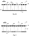
- the figure 2b schematically shows the acoustic attenuation panel 20 of the figure 2a seen in section.
- the arrow F indicates the direction of the flow of the air (or gas) flow to which the panel is subjected under normal operating conditions, that is to say when it is integrated into a turbojet engine nacelle, and that the turbojet is in operation, in particular in flight.
- the acoustic skin 26 comprises a plurality of acoustic openings 260, obtained by piercing the skin in a direction substantially perpendicular thereto, and materialized by the angle ⁇ , the value of which is 90 °.
- the figure 3 represents an acoustic attenuation panel 30 in accordance with the invention.
- arrow F also indicates the direction of the air flow to which the panel is subjected under normal operating conditions. In particular, the air flow goes from upstream to downstream of the propulsion unit in which the panel is integrated.
- the panel 30 comprises a solid support skin 34 and a perforated acoustic skin 36. Between the support skin 34 and the acoustic skin 36 is disposed a cellular core 32.
- the acoustic skin 36 comprises a plurality of acoustic openings 360.
- the acoustic openings 360 are inclined upstream with respect to the direction of circulation of the flow of air (or gas) materialized by the arrow F.
- the acoustic openings 360 are inclined. forward (or upstream) of the propulsion assembly when the panel is integrated into such an assembly.
- the acoustic openings 360 are obtained by drilling carried out in an oblique direction relative to the direction normal to the skin, materialized by the drilling angle ⁇ (or angle of inclination).
- the value of the drilling angle ⁇ is between 10 ° and 40 °.
- the forward inclination of the acoustic openings 360 has the effect of substantially reducing the acoustic resistance of the acoustic attenuation panel in the presence of a grazing flow, therefore when the propulsion assembly to which the panel is integrated. sound attenuation is in operation. Consequently, with equal acoustic resistance, it is possible to reduce the rate of open area.
- an acoustic skin drilled obliquely with a drilling angle ⁇ of 20 ° and an open area rate of 9% will have an acoustic behavior equivalent to an acoustic skin pierced perpendicularly (as in the example of figures 2a and 2b ) with an open area rate of 14%.
- the reduction in the rate of open area authorized by the invention therefore makes it possible to reduce the time and costs associated with drilling operations.
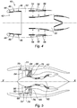
- FIG 4 it is also possible to jointly use acoustic attenuation panels in accordance with the invention, but having different drilling angle values ⁇ , and / or to provide, for the same acoustic attenuation panel, zones with openings of different inclinations.
- the figure 4 thus represents a propulsion unit comprising a turbojet 50 housed in a nacelle 40, the air inlet 42 of which is provided with an acoustic coating.
- This coating comprises acoustic attenuation panels distributed, from upstream to downstream of the nacelle 40, in several zones (in the example three zones) having a different acoustic piercing angle.
- a first zone 44 comprises acoustic attenuation panels having the highest drilling angle of the coating, for example 20 °.
- a second zone 46 located downstream of the first zone 44, comprises acoustic attenuation panels having a lower drilling angle than for the first zone 44, for example of 10 °.
- a third zone 48 located downstream of the second zone 46, comprises acoustic attenuation panels having a lower drilling angle than for the second zone, and in particular a zero drilling angle.
- the zones 44, 46, 48 are located upstream of the fan 52 of the turbojet 50 housed in the nacelle 40.
- provision will be made for the drilling angle to decrease. from upstream to downstream of the nacelle.
- a reverse progression will be provided: the drilling angle will increase from upstream to downstream of the propulsion assembly.
- the figure 4 thus shows a second acoustic coating disposed downstream of the fan 52.
- a first zone 54 comprises acoustic attenuation panels having the lowest piercing angle of this second coating, and in particular a zero piercing angle.
- a second zone 56 located downstream of the first zone 54, comprises acoustic attenuation panels having a drilling angle greater than for the first zone 54, for example of 10 °.
- a third zone 58 located downstream of the second zone 56, comprises acoustic attenuation panels having the highest drilling angle of the coating, for example a drilling angle of 20 °.
- the figure 5 shows an example of a propulsion assembly comprising acoustic attenuation panels in accordance with the invention arranged in certain parts of the turbojet.
- the propulsion unit of the figure 5 comprises a turbojet 60 of longitudinal axis XX, housed in a nacelle 62.
- the turbojet 60 comprises a fan 64 and, downstream thereof, a stator comprising blades 66.
- the fan 64 and the stator are surrounded by a casing 68 blower.
- Acoustic attenuation panels in accordance with the invention are arranged in particular on the internal surface of the fan casing 68, in the areas referenced 70, 72, 74, 76, these areas being respectively located downstream of the fan 64, facing each other.
- the turbojet 60 comprises, downstream of the fan 64, a casing 76 delimiting the internal surface 82 of the secondary stream 78 and the surface 84 of the primary duct 80, the zones 82 and 84 also comprising one or more acoustic attenuation panels in accordance with the invention.
- the flow has an angle of gyration ⁇ .
- angle ⁇ In order to better adapt the acoustic treatment in this area, as shown in the figure 6 , in addition to the inclination of the acoustic openings upstream of the propulsion unit of the drilling angle ⁇ , it is possible to introduce an inclination of angle ⁇ , to compensate for the gyration movement of the air flow, so that the axis of the acoustic openings is locally always oriented in the direction of the flow.
Landscapes
- Engineering & Computer Science (AREA)
- Chemical & Material Sciences (AREA)
- Combustion & Propulsion (AREA)
- Mechanical Engineering (AREA)
- General Engineering & Computer Science (AREA)
- Aviation & Aerospace Engineering (AREA)
- Physics & Mathematics (AREA)
- Acoustics & Sound (AREA)
- Multimedia (AREA)
- Structures Of Non-Positive Displacement Pumps (AREA)
Description
- La présente invention se rapporte au domaine de l'atténuation acoustique dans les nacelles et dans les turboréacteurs d'aéronefs, et plus généralement dans les ensembles propulsifs d'aéronefs.
- Les émissions sonores engendrées par les turboréacteurs d'un avion sont particulièrement intenses au moment du décollage, alors que l'avion se trouve en général à proximité de zones habitées.
- De nombreuses recherches portant sur la manière de réduire les émissions sonores engendrées par les turboréacteurs d'aéronefs ont été menées ces dernières années.
- Ces recherches ont notamment conduit à la mise en place de panneaux d'atténuation acoustique dans la nacelle entourant le turboréacteur ainsi que dans certaines parties (telles que le carter de soufflante) du turboréacteur lui-même, en particulier dans les zones où les émissions sonores sont les plus importantes.
- Ces panneaux fonctionnent en général selon le principe des résonateurs de Helmholtz, et comprennent à cet effet un ensemble de cavités prises en sandwich entre une peau pleine d'une part, et une peau perforée d'autre part.
- La peau perforée est orientée vers la zone d'émission de bruit, de sorte que les ondes acoustiques peuvent pénétrer par les ouvertures de la peau perforée à l'intérieur des cavités. L'énergie acoustique est dissipée par effet visquo-thermique dans les trous de la peau perforée. La hauteur des cavités permet de choisir la bande de fréquence cible.
- Outre leur fonction d'atténuation acoustique, ces panneaux assurent deux autres fonctions :
- une fonction aérodynamique : la peau perforée étant en contact avec les flux d'air et de gaz circulant à travers le turboréacteur et la nacelle, la peau perforée canalise le flux et doit perturber le moins possibles ces écoulements ;
- une fonction de reprise d'efforts : par l'intermédiaire du sandwich, le panneau d'atténuation acoustique est à même de reprendre certains des efforts subis par la nacelle.
- La peau perforée d'un panneau d'atténuation acoustique est généralement obtenue par perçage d'une peau initialement pleine, au moyen de forets, le perçage étant réalisé selon une direction sensiblement perpendiculaire à la peau. Le motif de perçage (distance entre les trous, diamètre des trous) est optimisé afin que la peau perforée présente la résistance acoustique souhaitée (par exemple, une résistance acoustique proche de celle de l'air en amont de la soufflante du turboréacteur, et une résistance acoustique de l'ordre de deux à trois fois la résistance acoustique de l'air en aval de la soufflante) en présence d'un écoulement rasant. Une peau perforée est ainsi généralement caractérisée par son taux de surface ouverte (couramment dénommé « POA », pour « percentage of open area »). Ce taux, exprimé en pourcentage, est représentatif de la surface occupée par les ouvertures acoustiques rapportée à la surface totale de la peau acoustique. Pour un diamètre de perçage donné, plus ce taux est grand, plus grand est le nombre de perçages.
- Or, les opérations de perçage sont complexes et coûteuses, et il existe un fort intérêt de limiter l'importance de ces opérations, notamment en diminuant autant que possible le taux de surface ouverte. En effet, un taux de surface ouverte de 14% peut représenter près de 55 000 trous par m2, et on comprend donc que réduire ce taux présente de grands avantages en termes de durée et de coût de fabrication.
- Le document
EP 0 824 066 A1 divulgue un panneau de l'art antérieur. - La présente invention a pour objectif de pallier les différents inconvénients de l'état de la technique exposés ci-dessus.
- Elle concerne à cet effet un panneau d'atténuation acoustique selon la revendication 1 pour un ensemble propulsif comportant une nacelle et un turboréacteur, le panneau comportant une âme alvéolaire disposée entre une peau interne et une peau externe, dite peau acoustique, la peau acoustique comportant une pluralité d'ouvertures acoustiques, les ouvertures acoustiques étant inclinées d'un angle d'inclinaison non nul par rapport à la direction normale à la peau acoustique, vers l'amont par rapport au sens d'écoulement du flux d'air ou de gaz auquel est destiné à être soumis le panneau en conditions normales de fonctionnement, c'est-à-dire vers l'amont de l'ensemble propulsif lorsque ledit panneau est monté dans un tel ensemble.
- Ainsi, grâce à l'inclinaison des ouvertures acoustiques vers l'amont du flux auquel est soumis le panneau d'atténuation acoustique dans un ensemble propulsif en fonctionnement, on réduit substantiellement la résistance acoustique du panneau. Ainsi, à résistance acoustique égale, il est possible de diminuer fortement (par exemple de 30%) le taux de surface ouverte.
- Dans l'invention, l'angle d'inclinaison, ou angle de perçage, des ouvertures acoustiques est compris entre 10° et 40°.
- Dans une réalisation, les peaux interne et externe sont réalisées en matériaux composite à matrice organique.
- Dans une réalisation, les ouvertures acoustiques sont réalisées par perçage mécanique ou par perçage laser.
- L'invention concerne également un ensemble propulsif d'aéronef, ledit ensemble propulsif comprenant au moins un panneau tel que défini ci-dessus.
- Dans une réalisation, l'ensemble propulsif comporte une nacelle et un turboréacteur d'aéronef, le turboréacteur comportant notamment une soufflante.
- Dans une réalisation, l'ensemble propulsif comporte une pluralité de panneaux d'atténuation acoustique comportant des angles de perçage différents.
- Dans une réalisation, l'angle de perçage des panneaux est décroissant de l'amont vers l'aval de la nacelle lorsque ceux-ci sont situés en amont de la soufflante du turboréacteur, l'angle de perçage des panneaux étant croissant si les panneaux sont situés en aval de la soufflante.
- Dans une réalisation, le turboréacteur comporte un carter de soufflante entourant la soufflante, la surface interne du carter de soufflante comportant un ou plusieurs panneaux d'atténuation acoustique conformes à l'invention.
- Dans une réalisation, le turboréacteur comporte un redresseur situé en aval de la soufflante, le redresseur comportant une pluralité d'aubes, la surface externe des aubes de redresseur comportant un ou plusieurs panneaux d'atténuation acoustique conforme à l'invention.
- Dans une réalisation, le turboréacteur comporte, en aval de la soufflante, un carter délimitant la surface interne d'une veine secondaire et la surface externe d'une veine primaire, l'une et/ou l'autre de ces surfaces comportant un ou plusieurs panneaux d'atténuation acoustique conformes à l'invention.
- D'autres caractéristiques et avantages de la présente invention apparaîtront à la lumière de la description qui suit, faite en référence aux dessins annexés, parmi lesquels :
- la
figure 1 est une vue schématique en coupe longitudinale d'un ensemble propulsif, l'ensemble propulsif comportant une nacelle entourant un turboréacteur d'aéronef à double flux ; - les
figures 2a et2b représentent un panneau d'atténuation acoustique de type connu ; - la
figure 3 représente un panneau d'atténuation acoustique conforme à l'invention ; - la
figure 4 représente un ensemble propulsif dont la nacelle est équipée de panneaux d'atténuation acoustique conformes à l'invention ; - la
figure 5 représente un ensemble propulsif dont le turboréacteur est équipé de panneaux d'atténuation acoustique conformes à l'invention ; - la
figure 6 représente un détail d'un panneau d'atténuation acoustique équipant le turboréacteur de lafigure 5 . - Sur la
figure 1 , on a représenté schématiquement un ensemble propulsif conventionnel. Cet ensemble propulsif comporte une nacelle 1 conventionnelle, équipant un turboréacteur 2 à double flux. La nacelle 1 comporte une entrée d'air 3, située en amont d'une soufflante 4 du turboréacteur 2. En aval de la soufflante 4, la nacelle définit une veine de flux froid, ou veine secondaire 5, et une veine de flux chaud, ou veine primaire 6. - Classiquement, l'entrée d'air 3 comporte un revêtement d'atténuation acoustique 7, formé par l'assemblage de panneaux d'atténuation acoustique.
- La veine de flux froid 5 est délimitée par des parois radialement externe et interne, également revêtues au moins partiellement de panneaux d'atténuation acoustique 8 et 9 respectivement.
- Enfin, la veine de flux chaud 6 est terminée par une tuyère primaire et un cône d'éjection des gaz, revêtus au moins partiellement de panneaux d'atténuation acoustique 10, 11.
- Les emplacements des panneaux d'atténuation acoustique 7 à 11 correspondent aux parois de la nacelle au niveau desquelles se propage le bruit. La présence de ces panneaux d'atténuation acoustique permet ainsi de diminuer sensiblement le niveau sonore émis par l'ensemble propulsif de l'aéronef, notamment lors du décollage ou de l'atterrissage.
- La
figure 2a représente un panneau d'atténuation acoustique 20 conventionnel, comportant une âme alvéolaire 22 prise en sandwich entre une peau pleine 24, dite peau support, et une peau perforée 26, dite peau acoustique. L'âme alvéolaire comporte une pluralité d'alvéoles, dans l'exemple de section hexagonale (formant ainsi une structure dite en « nid d'abeilles »). Ces alvéoles forment les cavités acoustiques du panneau d'atténuation acoustique 20. L'âme alvéolaire est en général métallique tandis que la peau acoustique 26 et la peau support 24 sont couramment réalisées dans un matériau composite, notamment à base de fibres de carbone. - La
figure 2b représente schématiquement le panneau d'atténuation acoustique 20 de lafigure 2a vu en coupe. Sur lafigure 2b , la flèche F indique le sens de l'écoulement du flux d'air (ou de gaz) auquel le panneau est soumis en conditions de fonctionnement normales, c'est-à-dire lorsqu'il est intégré à une nacelle de turboréacteur, et que le turboréacteur est en fonctionnement, notamment en vol. Comme mentionné plus haut, la peau acoustique 26 comporte une pluralité d'ouvertures acoustiques 260, obtenues par perçage de la peau selon une direction sensiblement perpendiculaire à celle-ci, et matérialisée par l'angle α, dont la valeur est de 90°. - La
figure 3 représente un panneau d'atténuation acoustique 30 conforme à l'invention. Sur lafigure 3 , la flèche F indique également le sens de l'écoulement du flux d'air auquel le panneau est soumis en conditions de fonctionnement normales. En particulier, le flux d'air se dirige de l'amont vers l'aval de l'ensemble propulsif dans lequel le panneau est intégré. Le panneau 30 comporte une peau support 34 pleine et une peau acoustique 36 perforée. Entre la peau support 34 et la peau acoustique 36 est disposée une âme alvéolaire 32. La peau acoustique 36 comporte une pluralité d'ouvertures acoustiques 360. - Conformément à l'invention, les ouvertures acoustiques 360 sont inclinées vers l'amont par rapport au sens de circulation du flux d'air (ou de gaz) matérialisé par la flèche F. En d'autres termes, les ouvertures acoustiques 360 sont inclinées vers l'avant (ou vers l'amont) de l'ensemble propulsif lorsque le panneau est intégré à un tel ensemble. Les ouvertures acoustiques 360 sont obtenues par un perçage effectué selon une direction oblique relativement à la direction normale à la peau, matérialisée par l'angle de perçage β (ou angle d'inclinaison). La valeur de l'angle de perçage β est comprise entre 10° et 40°. Comme mentionné plus haut, l'inclinaison vers l'avant des ouvertures acoustiques 360 a pour effet de diminuer substantiellement la résistance acoustique du panneau d'atténuation acoustique en présence d'un écoulement rasant, donc lorsque l'ensemble propulsif auquel est intégré le panneau d'atténuation acoustique est en fonctionnement. Conséquemment, à résistance acoustique égale, il est possible de diminuer le taux de surface ouverte. A titre d'exemple, une peau acoustique percée obliquement avec un angle de perçage β de 20° et un taux de surface ouverte de 9% (comme dans l'exemple de la
figure 3 ) aura un comportement acoustique équivalent à une peau acoustique percée perpendiculairement (comme dans l'exemple desfigures 2a et2b ) avec un taux de surface ouverte de 14%. - La diminution du taux de surface ouverte qu'autorise l'invention permet donc de diminuer le temps et les coûts liés aux opérations de perçage.
- Comme montré sur la
figure 4 , il est en outre possible d'utiliser conjointement des panneaux d'atténuation acoustique conformes à l'invention, mais présentant des valeurs d'angle de perçage β différentes, et/ou de prévoir, pour un même panneau d'atténuation acoustique, des zones comportant des ouvertures d'inclinaisons différentes. Lafigure 4 représente ainsi un ensemble propulsif comportant un turboréacteur 50 logé dans une nacelle 40, dont l'entrée d'air 42 est pourvue d'un revêtement acoustique. Ce revêtement comprend des panneaux d'atténuation acoustique répartis, de l'amont vers l'aval de la nacelle 40, en plusieurs zones (dans l'exemple trois zones) présentant un angle de perçage acoustique différent. Une première zone 44 comporte des panneaux d'atténuation acoustique présentant l'angle de perçage le plus élevé du revêtement, par exemple de 20°. Une deuxième zone 46, située en aval de la première zone 44, comporte des panneaux d'atténuation acoustique présentant un angle de perçage moins élevé que pour la première zone 44, par exemple de 10°. Enfin, une troisième zone 48, située en aval de la deuxième zone 46, comporte des panneaux d'atténuation acoustique présentant un angle de perçage moins élevé que pour la deuxième zone, et notamment un angle de perçage nul. En faisant varier ainsi l'angle de manière décroissante de l'amont vers l'aval, on réalise un traitement acoustique dont la résistance acoustique varie le long de l'axe longitudinal de l'ensemble propulsif, ce qui rend la résistance acoustique mieux adaptée à la vitesse d'écoulement et au niveau sonore local. Faire varier l'angle de perçage permet d'obtenir, avec un taux de surface ouverte constant, un comportement acoustique équivalent à un panneau d'atténuation acoustique conventionnel dont le taux de surface ouverte serait variable. - Dans l'exemple décrit ci-dessus, on notera que les zones 44, 46, 48 sont situées en amont de la soufflante 52 du turboréacteur 50 logé dans la nacelle 40. Dans ce cas, on prévoira que l'angle de perçage est décroissant de l'amont vers l'aval de la nacelle. En revanche, pour des zones situées en aval de la soufflante 52, on prévoira une progression inverse : l'angle de perçage augmentera de l'amont vers l'aval de l'ensemble propulsif. La
figure 4 montre ainsi un deuxième revêtement acoustique disposé en aval de la soufflante 52. Une première zone 54 comporte des panneaux d'atténuation acoustique présentant l'angle de perçage le moins élevé de ce deuxième revêtement, et notamment un angle de perçage nul. Une deuxième zone 56, située en aval de la première zone 54, comporte des panneaux d'atténuation acoustique présentant un angle de perçage plus élevé que pour la première zone 54, par exemple de 10°. Enfin, une troisième zone 58, située en aval de la deuxième zone 56, comporte des panneaux d'atténuation acoustique présentant l'angle de perçage le plus élevé du revêtement, par exemple un angle de perçage de 20°. - La
figure 5 montre un exemple d'ensemble propulsif comportant des panneaux d'atténuation acoustique conforme à l'invention disposés dans certaines parties du turboréacteur. Ainsi, l'ensemble propulsif de lafigure 5 comporte un turboréacteur 60 d'axe longitudinal XX, logé dans une nacelle 62. Le turboréacteur 60 comporte une soufflante 64 et, en aval de celle-ci, un redresseur comportant des aubes 66. La soufflante 64 et le redresseur sont entourés par un carter 68 de soufflante. Des panneaux d'atténuation acoustique conformes à l'invention sont disposés notamment sur la surface interne du carter 68 de soufflante, dans les zones référencées 70, 72, 74, 76, ces zones étant situées respectivement en aval de la soufflante 64, en regard des aubes de la soufflante 64, entre la soufflante 64 et le redresseur, et en regard des aubes 66 du redresseur. Les aubes 66 du redresseur sont également équipées de panneaux d'atténuation acoustique conformes à l'invention. Le turboréacteur 60 comporte, en aval de la soufflante 64, un carter 76 délimitant la surface interne 82 de la veine secondaire 78 et la surface externe 84 de la veine primaire 80, les zones 82 et 84 comportant également un ou plusieurs panneaux d'atténuation acoustique conformes à l'invention. - Dans la zone située entre la soufflante 64 et les aubes 66 du redresseur, l'écoulement possède un angle de giration γ. Afin de mieux adapter le traitement acoustique dans cette zone, comme représenté sur la
figure 6 , on pourra, en plus de l'inclinaison des ouvertures acoustiques vers l'amont de l'ensemble propulsif de l'angle de perçage β, introduire une inclinaison d'angle γ, pour compenser le mouvement de giration du flux d'air, de sorte que l'axe des ouvertures acoustiques soit localement toujours orienté dans la direction de l'écoulement. - Bien entendu, la présente invention n'est nullement limitée aux modes de réalisation décrits et représentés.
Claims (9)
- Panneau (30) d'atténuation acoustique pour un ensemble propulsif comportant une nacelle et un turboréacteur, le panneau (30) comportant une âme alvéolaire (32) disposée entre une peau interne (34) et une peau externe (36), dite peau acoustique, la peau acoustique comportant une pluralité d'ouvertures acoustiques (360), les ouvertures acoustiques (360) étant inclinées, d'un angle d'inclinaison (β) non nul par rapport à la direction normale à la peau acoustique, vers l'amont par rapport au sens d'écoulement du flux d'air ou de gaz auquel est destiné à être soumis le panneau (30) en conditions normales de fonctionnement, c'est-à-dire vers l'amont de l'ensemble propulsif lorsque ledit panneau est monté dans un tel ensemble, caractérisé en ce que l'angle d'inclinaison (β), ou angle de perçage (β), est compris entre 10° et 40°.
- Panneau (30) selon la revendication précédente, dans lequel les peaux interne (34) et externe (36) sont réalisées en matériaux composite à matrice organique.
- Panneau (30) selon la revendication 1 ou 2, dans lequel les ouvertures acoustiques (360) sont réalisées par perçage mécanique ou par perçage laser.
- Ensemble propulsif d'aéronef, comportant une nacelle et un turboréacteur d'aéronef, le turboréacteur comportant notamment une soufflante, l'ensemble propulsif étant caractérisé en ce qu'il comporte au moins un panneau (30) d'atténuation acoustique conforme à l'une des revendications précédentes.
- Ensemble propulsif d'aéronef selon la revendication précédente, comportant une pluralité de panneaux (30) d'atténuation acoustique comportant des angles de perçage (β) différents.
- Ensemble propulsif d'aéronef selon la revendication précédente, dans laquelle l'angle de perçage (β) des panneaux (30) est décroissant de l'amont vers l'aval de la nacelle lorsque ceux-ci sont situés en amont de la soufflante du turboréacteur, l'angle de perçage (β) des panneaux (30) étant croissant si les panneaux sont situés en aval de la soufflante.
- Ensemble propulsif d'aéronef selon l'une des revendications 4 à 6, dans lequel le turboréacteur comporte un carter de soufflante entourant la soufflante, caractérisé en ce que la surface interne du carter de soufflante comporte un ou plusieurs panneaux (30) d'atténuation acoustique.
- Ensemble propulsif d'aéronef selon l'une des revendications 4 à 6, dans lequel le turboréacteur comporte un redresseur situé en aval de la soufflante, le redresseur comportant une pluralité d'aubes, l'ensemble propulsif étant caractérisé en ce que la surface externe des aubes de redresseur comporte un ou plusieurs panneaux (30) d'atténuation acoustique.
- Ensemble propulsif d'aéronef selon l'une des revendications 4 à 8, dans lequel le turboréacteur comporte, en aval de la soufflante, un carter délimitant la surface interne d'une veine secondaire et la surface externe d'une veine primaire, l'une et/ou l'autre de ces surfaces comportant un panneau (30) d'atténuation acoustique.
Applications Claiming Priority (2)
| Application Number | Priority Date | Filing Date | Title |
|---|---|---|---|
| FR1657412A FR3054607B1 (fr) | 2016-07-29 | 2016-07-29 | Panneau d’attenuation acoustique pour ensemble propulsif d’aeronef et ensemble propulsif comportant un tel panneau |
| PCT/FR2017/052116 WO2018020174A1 (fr) | 2016-07-29 | 2017-07-27 | Panneau d'atténuation acoustique pour ensemble propulsif d'aéronef et ensemble propulsif comportant un tel panneau |
Publications (2)
| Publication Number | Publication Date |
|---|---|
| EP3491228A1 EP3491228A1 (fr) | 2019-06-05 |
| EP3491228B1 true EP3491228B1 (fr) | 2021-10-13 |
Family
ID=57121364
Family Applications (1)
| Application Number | Title | Priority Date | Filing Date |
|---|---|---|---|
| EP17757802.8A Active EP3491228B1 (fr) | 2016-07-29 | 2017-07-27 | Panneau d'atténuation acoustique pour ensemble propulsif d'aéronef et ensemble propulsif comportant un tel panneau |
Country Status (4)
| Country | Link |
|---|---|
| US (1) | US11220346B2 (fr) |
| EP (1) | EP3491228B1 (fr) |
| FR (1) | FR3054607B1 (fr) |
| WO (1) | WO2018020174A1 (fr) |
Cited By (1)
| Publication number | Priority date | Publication date | Assignee | Title |
|---|---|---|---|---|
| WO2025224400A1 (fr) * | 2024-04-26 | 2025-10-30 | Safran Nacelles | Procédé de fabrication d'une âme alvéolaire pour panneau d'atténuation acoustique |
Families Citing this family (6)
| Publication number | Priority date | Publication date | Assignee | Title |
|---|---|---|---|---|
| FR3101723B1 (fr) * | 2019-10-08 | 2022-07-22 | Safran Nacelles | Panneau d’atténuation acoustique pour onde basses fréquences |
| CN113898476B (zh) * | 2020-06-22 | 2022-11-08 | 中国航发商用航空发动机有限责任公司 | 声衬件、动力推进系统以及入口板组 |
| EP4334931A2 (fr) * | 2021-05-04 | 2024-03-13 | Safran Aircraft Engines | Meta-materiau acoustique et procede pour sa fabrication additive |
| FR3126340B1 (fr) * | 2021-08-30 | 2023-11-03 | Safran Nacelles | Panneau acoustique à cavités obliques |
| FR3129241A1 (fr) * | 2021-11-17 | 2023-05-19 | Airbus Operations | Peau poreuse pourvue d’une pluralité de bandes et panneau d’atténuation acoustique comprenant une telle peau poreuse. |
| EP4303124A1 (fr) * | 2022-07-07 | 2024-01-10 | Lilium eAircraft GmbH | Moteur de ventilateur entraîné électriquement comportant des aubes directrices dotées de revêtements acoustiques |
Family Cites Families (15)
| Publication number | Priority date | Publication date | Assignee | Title |
|---|---|---|---|---|
| CA1027002A (fr) * | 1974-08-30 | 1978-02-28 | Horst W.W. Hehmann | Suppresseur de bruit a traitement phase pour les gaines acoustiques |
| US4137992A (en) * | 1976-12-30 | 1979-02-06 | The Boeing Company | Turbojet engine nozzle for attenuating core and turbine noise |
| US4537277A (en) * | 1982-12-03 | 1985-08-27 | The Secretary Of State For Defence In Her Britannic Majesty's Government Of The United Kingdom Of Great Britain And Northern Ireland | Silencer for high velocity gas flow |
| FR2752392B1 (fr) * | 1996-08-14 | 1999-04-23 | Hispano Suiza Sa | Panneau sandwich en nid d'abeille ventile et procede de ventilation d'un tel panneau |
| GB0016149D0 (en) * | 2000-06-30 | 2000-08-23 | Short Brothers Plc | A noise attenuation panel |
| GB2391059B (en) * | 2000-06-30 | 2005-02-16 | Short Brothers Plc | A noise attenuation panel |
| US6439340B1 (en) * | 2000-11-17 | 2002-08-27 | Astech Manufacturing, Inc. | Acoustically treated structurally reinforced sound absorbing panel |
| US7267297B2 (en) * | 2004-09-02 | 2007-09-11 | The Boeing Company | Integrated axially varying engine muffler, and associated methods and systems |
| US20060169532A1 (en) * | 2005-02-03 | 2006-08-03 | Patrick William P | Acoustic liner with nonuniform impedance |
| US20060169533A1 (en) * | 2005-02-03 | 2006-08-03 | Patrick William P | Acoustic liner with a nonuniform depth backwall |
| FR2915522A1 (fr) * | 2007-04-30 | 2008-10-31 | Airbus France Sas | Panneau acoustique a caracteristique acoustique variable |
| US20100206664A1 (en) * | 2007-07-12 | 2010-08-19 | Rolls-Royce Plc | Acoustic panel |
| US7717229B2 (en) * | 2008-05-09 | 2010-05-18 | Siemens Energy, Inc. | Gas turbine exhaust sound suppressor and associated methods |
| FR2962586B1 (fr) * | 2010-07-09 | 2013-05-24 | Airbus Operations Sas | Panneau pour le traitement acoustique |
| FR3057028B1 (fr) * | 2016-09-30 | 2020-08-14 | Safran Aircraft Engines | Deflecteur de flux d'un systeme de vanne de decharge, systeme de vanne de decharge et turbomachine comprenant un tel systeme de vanne de decharge |
-
2016
- 2016-07-29 FR FR1657412A patent/FR3054607B1/fr not_active Expired - Fee Related
-
2017
- 2017-07-27 WO PCT/FR2017/052116 patent/WO2018020174A1/fr not_active Ceased
- 2017-07-27 EP EP17757802.8A patent/EP3491228B1/fr active Active
-
2019
- 2019-01-29 US US16/260,972 patent/US11220346B2/en active Active
Cited By (2)
| Publication number | Priority date | Publication date | Assignee | Title |
|---|---|---|---|---|
| WO2025224400A1 (fr) * | 2024-04-26 | 2025-10-30 | Safran Nacelles | Procédé de fabrication d'une âme alvéolaire pour panneau d'atténuation acoustique |
| FR3161597A1 (fr) * | 2024-04-26 | 2025-10-31 | Safran Nacelles | Procédé de fabrication d’une âme alvéolaire pour panneau d’atténuation acoustique |
Also Published As
| Publication number | Publication date |
|---|---|
| EP3491228A1 (fr) | 2019-06-05 |
| US11220346B2 (en) | 2022-01-11 |
| US20190161200A1 (en) | 2019-05-30 |
| FR3054607A1 (fr) | 2018-02-02 |
| FR3054607B1 (fr) | 2020-02-28 |
| WO2018020174A1 (fr) | 2018-02-01 |
Similar Documents
| Publication | Publication Date | Title |
|---|---|---|
| WO2018020174A1 (fr) | Panneau d'atténuation acoustique pour ensemble propulsif d'aéronef et ensemble propulsif comportant un tel panneau | |
| EP3237741B1 (fr) | Panneau d'atténuation acoustique pour nacelle de turboréacteur | |
| CA2850243C (fr) | Pale pour une helice de turbomachine, notamment a soufflante non carenee, helice et turbomachine correspondantes | |
| EP2763892B1 (fr) | Procédé de fabrication d'un panneau d'absorption acoustique | |
| FR2787513A1 (fr) | Dispositif d'echappement multicanal de turbomachine traite acoustiquement | |
| EP3489487A1 (fr) | Panneau d'atténuation acoustique pour aéronef | |
| FR2727725A1 (fr) | Structure aerodynamique, procede de reglage de couche limite groupe propulseur et aeronef le comportant | |
| EP2318683A2 (fr) | Panneau d'atténuation acoustique pour nacelle de moteur d'aéronef | |
| CA2761666A1 (fr) | Procede d'assemblage d'une protection thermique sur une structure interne fixe de nacelle de turboreacteur | |
| EP3921527A1 (fr) | Entree d'air d'une nacelle de turboreacteur d'aeronef comportant des ouvertures de ventilation d'un flux d'air chaud de degivrage | |
| EP4052250B1 (fr) | Panneau d'atténuation acoustique et ses procédés de fabrication | |
| WO2022117968A1 (fr) | Panneau multicellulaire d'attenuation acoustique a hauteur variable | |
| EP3552951B1 (fr) | Panneau d'atténuation acoustique pour aéronef présentant des propriétés d'absorption acoustique combinées | |
| EP3921528A1 (fr) | Entree d'air d'une nacelle de turboreacteur d'aeronef comportant des ouvertures de ventilation d'un flux d'air chaud de degivrage | |
| EP4367022A1 (fr) | Propulseur aeronautique | |
| EP2839458A1 (fr) | Panneau mince d'absorption d'ondes acoustiques émises par un turboréacteur de nacelle d'aéronef, et nacelle équipée d'un tel panneau | |
| FR2962586A1 (fr) | Panneau pour le traitement acoustique | |
| FR2979391A1 (fr) | Turbomachine comportant un element grillage circonferentiel entre deux helices contrarotatives non carenees | |
| WO2017109430A1 (fr) | Turbomachine à hélice à clipping inversé | |
| EP4066235B1 (fr) | Pastille resonante et cellule de traitement acoustique dotee d'une telle pastille | |
| WO2013121150A1 (fr) | Ensemble d'arriere-corps de moteur aeronautique a turbine a gaz | |
| FR3125089A1 (fr) | Propulseur aeronautique | |
| EP3921525B1 (fr) | Entree d'air d'une nacelle de turboreacteur d'aeronef comportant des ouvertures de ventilation d'un flux d'air chaud de degivrage | |
| FR3159200A1 (fr) | Tuyere d’ejection de flux d’air a section de sortie constante equipee d’un dispositif de reglage de veine et turbomachine equipee d’une telle tuyere. | |
| WO2022101579A1 (fr) | Revetement de traitement acoustique comprenant un metaporeux ordonne replie |
Legal Events
| Date | Code | Title | Description |
|---|---|---|---|
| STAA | Information on the status of an ep patent application or granted ep patent |
Free format text: STATUS: UNKNOWN |
|
| STAA | Information on the status of an ep patent application or granted ep patent |
Free format text: STATUS: THE INTERNATIONAL PUBLICATION HAS BEEN MADE |
|
| PUAI | Public reference made under article 153(3) epc to a published international application that has entered the european phase |
Free format text: ORIGINAL CODE: 0009012 |
|
| STAA | Information on the status of an ep patent application or granted ep patent |
Free format text: STATUS: REQUEST FOR EXAMINATION WAS MADE |
|
| 17P | Request for examination filed |
Effective date: 20190222 |
|
| AK | Designated contracting states |
Kind code of ref document: A1 Designated state(s): AL AT BE BG CH CY CZ DE DK EE ES FI FR GB GR HR HU IE IS IT LI LT LU LV MC MK MT NL NO PL PT RO RS SE SI SK SM TR |
|
| AX | Request for extension of the european patent |
Extension state: BA ME |
|
| DAV | Request for validation of the european patent (deleted) | ||
| DAX | Request for extension of the european patent (deleted) | ||
| GRAP | Despatch of communication of intention to grant a patent |
Free format text: ORIGINAL CODE: EPIDOSNIGR1 |
|
| STAA | Information on the status of an ep patent application or granted ep patent |
Free format text: STATUS: GRANT OF PATENT IS INTENDED |
|
| INTG | Intention to grant announced |
Effective date: 20210507 |
|
| GRAS | Grant fee paid |
Free format text: ORIGINAL CODE: EPIDOSNIGR3 |
|
| GRAA | (expected) grant |
Free format text: ORIGINAL CODE: 0009210 |
|
| STAA | Information on the status of an ep patent application or granted ep patent |
Free format text: STATUS: THE PATENT HAS BEEN GRANTED |
|
| AK | Designated contracting states |
Kind code of ref document: B1 Designated state(s): AL AT BE BG CH CY CZ DE DK EE ES FI FR GB GR HR HU IE IS IT LI LT LU LV MC MK MT NL NO PL PT RO RS SE SI SK SM TR |
|
| REG | Reference to a national code |
Ref country code: GB Ref legal event code: FG4D Free format text: NOT ENGLISH |
|
| REG | Reference to a national code |
Ref country code: CH Ref legal event code: EP |
|
| REG | Reference to a national code |
Ref country code: DE Ref legal event code: R096 Ref document number: 602017047588 Country of ref document: DE |
|
| REG | Reference to a national code |
Ref country code: IE Ref legal event code: FG4D Free format text: LANGUAGE OF EP DOCUMENT: FRENCH |
|
| REG | Reference to a national code |
Ref country code: AT Ref legal event code: REF Ref document number: 1438365 Country of ref document: AT Kind code of ref document: T Effective date: 20211115 |
|
| REG | Reference to a national code |
Ref country code: LT Ref legal event code: MG9D |
|
| REG | Reference to a national code |
Ref country code: NL Ref legal event code: MP Effective date: 20211013 |
|
| REG | Reference to a national code |
Ref country code: AT Ref legal event code: MK05 Ref document number: 1438365 Country of ref document: AT Kind code of ref document: T Effective date: 20211013 |
|
| PG25 | Lapsed in a contracting state [announced via postgrant information from national office to epo] |
Ref country code: RS Free format text: LAPSE BECAUSE OF FAILURE TO SUBMIT A TRANSLATION OF THE DESCRIPTION OR TO PAY THE FEE WITHIN THE PRESCRIBED TIME-LIMIT Effective date: 20211013 Ref country code: LT Free format text: LAPSE BECAUSE OF FAILURE TO SUBMIT A TRANSLATION OF THE DESCRIPTION OR TO PAY THE FEE WITHIN THE PRESCRIBED TIME-LIMIT Effective date: 20211013 Ref country code: FI Free format text: LAPSE BECAUSE OF FAILURE TO SUBMIT A TRANSLATION OF THE DESCRIPTION OR TO PAY THE FEE WITHIN THE PRESCRIBED TIME-LIMIT Effective date: 20211013 Ref country code: BG Free format text: LAPSE BECAUSE OF FAILURE TO SUBMIT A TRANSLATION OF THE DESCRIPTION OR TO PAY THE FEE WITHIN THE PRESCRIBED TIME-LIMIT Effective date: 20220113 Ref country code: AT Free format text: LAPSE BECAUSE OF FAILURE TO SUBMIT A TRANSLATION OF THE DESCRIPTION OR TO PAY THE FEE WITHIN THE PRESCRIBED TIME-LIMIT Effective date: 20211013 |
|
| PG25 | Lapsed in a contracting state [announced via postgrant information from national office to epo] |
Ref country code: IS Free format text: LAPSE BECAUSE OF FAILURE TO SUBMIT A TRANSLATION OF THE DESCRIPTION OR TO PAY THE FEE WITHIN THE PRESCRIBED TIME-LIMIT Effective date: 20220213 Ref country code: SE Free format text: LAPSE BECAUSE OF FAILURE TO SUBMIT A TRANSLATION OF THE DESCRIPTION OR TO PAY THE FEE WITHIN THE PRESCRIBED TIME-LIMIT Effective date: 20211013 Ref country code: PT Free format text: LAPSE BECAUSE OF FAILURE TO SUBMIT A TRANSLATION OF THE DESCRIPTION OR TO PAY THE FEE WITHIN THE PRESCRIBED TIME-LIMIT Effective date: 20220214 Ref country code: PL Free format text: LAPSE BECAUSE OF FAILURE TO SUBMIT A TRANSLATION OF THE DESCRIPTION OR TO PAY THE FEE WITHIN THE PRESCRIBED TIME-LIMIT Effective date: 20211013 Ref country code: NO Free format text: LAPSE BECAUSE OF FAILURE TO SUBMIT A TRANSLATION OF THE DESCRIPTION OR TO PAY THE FEE WITHIN THE PRESCRIBED TIME-LIMIT Effective date: 20220113 Ref country code: NL Free format text: LAPSE BECAUSE OF FAILURE TO SUBMIT A TRANSLATION OF THE DESCRIPTION OR TO PAY THE FEE WITHIN THE PRESCRIBED TIME-LIMIT Effective date: 20211013 Ref country code: LV Free format text: LAPSE BECAUSE OF FAILURE TO SUBMIT A TRANSLATION OF THE DESCRIPTION OR TO PAY THE FEE WITHIN THE PRESCRIBED TIME-LIMIT Effective date: 20211013 Ref country code: HR Free format text: LAPSE BECAUSE OF FAILURE TO SUBMIT A TRANSLATION OF THE DESCRIPTION OR TO PAY THE FEE WITHIN THE PRESCRIBED TIME-LIMIT Effective date: 20211013 Ref country code: GR Free format text: LAPSE BECAUSE OF FAILURE TO SUBMIT A TRANSLATION OF THE DESCRIPTION OR TO PAY THE FEE WITHIN THE PRESCRIBED TIME-LIMIT Effective date: 20220114 Ref country code: ES Free format text: LAPSE BECAUSE OF FAILURE TO SUBMIT A TRANSLATION OF THE DESCRIPTION OR TO PAY THE FEE WITHIN THE PRESCRIBED TIME-LIMIT Effective date: 20211013 |
|
| REG | Reference to a national code |
Ref country code: DE Ref legal event code: R097 Ref document number: 602017047588 Country of ref document: DE |
|
| PG25 | Lapsed in a contracting state [announced via postgrant information from national office to epo] |
Ref country code: SM Free format text: LAPSE BECAUSE OF FAILURE TO SUBMIT A TRANSLATION OF THE DESCRIPTION OR TO PAY THE FEE WITHIN THE PRESCRIBED TIME-LIMIT Effective date: 20211013 Ref country code: SK Free format text: LAPSE BECAUSE OF FAILURE TO SUBMIT A TRANSLATION OF THE DESCRIPTION OR TO PAY THE FEE WITHIN THE PRESCRIBED TIME-LIMIT Effective date: 20211013 Ref country code: RO Free format text: LAPSE BECAUSE OF FAILURE TO SUBMIT A TRANSLATION OF THE DESCRIPTION OR TO PAY THE FEE WITHIN THE PRESCRIBED TIME-LIMIT Effective date: 20211013 Ref country code: EE Free format text: LAPSE BECAUSE OF FAILURE TO SUBMIT A TRANSLATION OF THE DESCRIPTION OR TO PAY THE FEE WITHIN THE PRESCRIBED TIME-LIMIT Effective date: 20211013 Ref country code: DK Free format text: LAPSE BECAUSE OF FAILURE TO SUBMIT A TRANSLATION OF THE DESCRIPTION OR TO PAY THE FEE WITHIN THE PRESCRIBED TIME-LIMIT Effective date: 20211013 Ref country code: CZ Free format text: LAPSE BECAUSE OF FAILURE TO SUBMIT A TRANSLATION OF THE DESCRIPTION OR TO PAY THE FEE WITHIN THE PRESCRIBED TIME-LIMIT Effective date: 20211013 |
|
| PLBE | No opposition filed within time limit |
Free format text: ORIGINAL CODE: 0009261 |
|
| STAA | Information on the status of an ep patent application or granted ep patent |
Free format text: STATUS: NO OPPOSITION FILED WITHIN TIME LIMIT |
|
| 26N | No opposition filed |
Effective date: 20220714 |
|
| PG25 | Lapsed in a contracting state [announced via postgrant information from national office to epo] |
Ref country code: AL Free format text: LAPSE BECAUSE OF FAILURE TO SUBMIT A TRANSLATION OF THE DESCRIPTION OR TO PAY THE FEE WITHIN THE PRESCRIBED TIME-LIMIT Effective date: 20211013 |
|
| PG25 | Lapsed in a contracting state [announced via postgrant information from national office to epo] |
Ref country code: SI Free format text: LAPSE BECAUSE OF FAILURE TO SUBMIT A TRANSLATION OF THE DESCRIPTION OR TO PAY THE FEE WITHIN THE PRESCRIBED TIME-LIMIT Effective date: 20211013 |
|
| PG25 | Lapsed in a contracting state [announced via postgrant information from national office to epo] |
Ref country code: MC Free format text: LAPSE BECAUSE OF FAILURE TO SUBMIT A TRANSLATION OF THE DESCRIPTION OR TO PAY THE FEE WITHIN THE PRESCRIBED TIME-LIMIT Effective date: 20211013 |
|
| REG | Reference to a national code |
Ref country code: CH Ref legal event code: PL |
|
| REG | Reference to a national code |
Ref country code: BE Ref legal event code: MM Effective date: 20220731 |
|
| PG25 | Lapsed in a contracting state [announced via postgrant information from national office to epo] |
Ref country code: LU Free format text: LAPSE BECAUSE OF NON-PAYMENT OF DUE FEES Effective date: 20220727 Ref country code: LI Free format text: LAPSE BECAUSE OF NON-PAYMENT OF DUE FEES Effective date: 20220731 Ref country code: CH Free format text: LAPSE BECAUSE OF NON-PAYMENT OF DUE FEES Effective date: 20220731 |
|
| PG25 | Lapsed in a contracting state [announced via postgrant information from national office to epo] |
Ref country code: IT Free format text: LAPSE BECAUSE OF FAILURE TO SUBMIT A TRANSLATION OF THE DESCRIPTION OR TO PAY THE FEE WITHIN THE PRESCRIBED TIME-LIMIT Effective date: 20211013 Ref country code: BE Free format text: LAPSE BECAUSE OF NON-PAYMENT OF DUE FEES Effective date: 20220731 |
|
| PG25 | Lapsed in a contracting state [announced via postgrant information from national office to epo] |
Ref country code: IE Free format text: LAPSE BECAUSE OF NON-PAYMENT OF DUE FEES Effective date: 20220727 |
|
| PG25 | Lapsed in a contracting state [announced via postgrant information from national office to epo] |
Ref country code: HU Free format text: LAPSE BECAUSE OF FAILURE TO SUBMIT A TRANSLATION OF THE DESCRIPTION OR TO PAY THE FEE WITHIN THE PRESCRIBED TIME-LIMIT; INVALID AB INITIO Effective date: 20170727 |
|
| PG25 | Lapsed in a contracting state [announced via postgrant information from national office to epo] |
Ref country code: MK Free format text: LAPSE BECAUSE OF FAILURE TO SUBMIT A TRANSLATION OF THE DESCRIPTION OR TO PAY THE FEE WITHIN THE PRESCRIBED TIME-LIMIT Effective date: 20211013 Ref country code: CY Free format text: LAPSE BECAUSE OF FAILURE TO SUBMIT A TRANSLATION OF THE DESCRIPTION OR TO PAY THE FEE WITHIN THE PRESCRIBED TIME-LIMIT Effective date: 20211013 |
|
| PG25 | Lapsed in a contracting state [announced via postgrant information from national office to epo] |
Ref country code: TR Free format text: LAPSE BECAUSE OF FAILURE TO SUBMIT A TRANSLATION OF THE DESCRIPTION OR TO PAY THE FEE WITHIN THE PRESCRIBED TIME-LIMIT Effective date: 20211013 |
|
| PG25 | Lapsed in a contracting state [announced via postgrant information from national office to epo] |
Ref country code: MT Free format text: LAPSE BECAUSE OF FAILURE TO SUBMIT A TRANSLATION OF THE DESCRIPTION OR TO PAY THE FEE WITHIN THE PRESCRIBED TIME-LIMIT Effective date: 20211013 |
|
| PGFP | Annual fee paid to national office [announced via postgrant information from national office to epo] |
Ref country code: DE Payment date: 20250722 Year of fee payment: 9 |
|
| PGFP | Annual fee paid to national office [announced via postgrant information from national office to epo] |
Ref country code: GB Payment date: 20250724 Year of fee payment: 9 |
|
| PGFP | Annual fee paid to national office [announced via postgrant information from national office to epo] |
Ref country code: FR Payment date: 20250722 Year of fee payment: 9 |