EP3490732B1 - Machine for filling bottles and the like comprising handling device for washing and sanitising - Google Patents
Machine for filling bottles and the like comprising handling device for washing and sanitising Download PDFInfo
- Publication number
- EP3490732B1 EP3490732B1 EP17740418.3A EP17740418A EP3490732B1 EP 3490732 B1 EP3490732 B1 EP 3490732B1 EP 17740418 A EP17740418 A EP 17740418A EP 3490732 B1 EP3490732 B1 EP 3490732B1
- Authority
- EP
- European Patent Office
- Prior art keywords
- handling device
- machine
- conduit
- machine according
- washing
- Prior art date
- Legal status (The legal status is an assumption and is not a legal conclusion. Google has not performed a legal analysis and makes no representation as to the accuracy of the status listed.)
- Active
Links
Images

Classifications
-
- B—PERFORMING OPERATIONS; TRANSPORTING
- B25—HAND TOOLS; PORTABLE POWER-DRIVEN TOOLS; MANIPULATORS
- B25J—MANIPULATORS; CHAMBERS PROVIDED WITH MANIPULATION DEVICES
- B25J11/00—Manipulators not otherwise provided for
- B25J11/008—Manipulators for service tasks
- B25J11/0085—Cleaning
-
- B—PERFORMING OPERATIONS; TRANSPORTING
- B08—CLEANING
- B08B—CLEANING IN GENERAL; PREVENTION OF FOULING IN GENERAL
- B08B3/00—Cleaning by methods involving the use or presence of liquid or steam
- B08B3/02—Cleaning by the force of jets or sprays
- B08B3/024—Cleaning by means of spray elements moving over the surface to be cleaned
-
- B—PERFORMING OPERATIONS; TRANSPORTING
- B08—CLEANING
- B08B—CLEANING IN GENERAL; PREVENTION OF FOULING IN GENERAL
- B08B5/00—Cleaning by methods involving the use of air flow or gas flow
- B08B5/02—Cleaning by the force of jets, e.g. blowing-out cavities
-
- B—PERFORMING OPERATIONS; TRANSPORTING
- B08—CLEANING
- B08B—CLEANING IN GENERAL; PREVENTION OF FOULING IN GENERAL
- B08B9/00—Cleaning hollow articles by methods or apparatus specially adapted thereto
-
- B—PERFORMING OPERATIONS; TRANSPORTING
- B67—OPENING, CLOSING OR CLEANING BOTTLES, JARS OR SIMILAR CONTAINERS; LIQUID HANDLING
- B67C—CLEANING, FILLING WITH LIQUIDS OR SEMILIQUIDS, OR EMPTYING, OF BOTTLES, JARS, CANS, CASKS, BARRELS, OR SIMILAR CONTAINERS, NOT OTHERWISE PROVIDED FOR; FUNNELS
- B67C3/00—Bottling liquids or semiliquids; Filling jars or cans with liquids or semiliquids using bottling or like apparatus; Filling casks or barrels with liquids or semiliquids
- B67C3/001—Cleaning of filling devices
- B67C3/005—Cleaning outside parts of filling devices
-
- B—PERFORMING OPERATIONS; TRANSPORTING
- B05—SPRAYING OR ATOMISING IN GENERAL; APPLYING FLUENT MATERIALS TO SURFACES, IN GENERAL
- B05B—SPRAYING APPARATUS; ATOMISING APPARATUS; NOZZLES
- B05B13/00—Machines or plants for applying liquids or other fluent materials to surfaces of objects or other work by spraying, not covered by groups B05B1/00 - B05B11/00
- B05B13/02—Means for supporting work; Arrangement or mounting of spray heads; Adaptation or arrangement of means for feeding work
- B05B13/04—Means for supporting work; Arrangement or mounting of spray heads; Adaptation or arrangement of means for feeding work the spray heads being moved during spraying operation
- B05B13/0431—Means for supporting work; Arrangement or mounting of spray heads; Adaptation or arrangement of means for feeding work the spray heads being moved during spraying operation with spray heads moved by robots or articulated arms, e.g. for applying liquid or other fluent material to three-dimensional [3D] surfaces
Definitions
- This invention relates to a machine for filling bottles, cartridges, syringes and the like.
- products and substances in liquid and/or powder form can be properly packaged in special containers, often suitable for containing a single dose, in order to facilitate their administration to patients.
- Such products and substances are therefore packaged in specific bottles, vials, cartridges (such as, for example, carpules used in syringes intended for the administration of local anaesthetics), syringes (such as ready-to-use syringes used for many miscellaneous applications) and similar products.
- cartridges such as, for example, carpules used in syringes intended for the administration of local anaesthetics
- syringes such as ready-to-use syringes used for many miscellaneous applications
- the tubs, nests and containers are of a standard type, manufactured by their suppliers, generally differing from those used for filling and constituting the first dimensional and structural requirement necessary for filling and sealing machines.
- the handling of the nests is normally carried out by multi-axis handling devices, which take them from a conveyor belt and transfer them, from time to time, to a specific operating area (where the filling, weighing or sealing, etc. is to be performed).
- the multi-axis handling devices have multiple grooves, sites and undercuts where dust and residues that are difficult to remove can accumulate.
- JP 2012 116495 describes a filling device in which a robot is used to carry out washing procedures. This robot has a conduit placed at least partially inside the robot and the latter is equipped with a spray nozzle. This configuration of the known procedure makes it difficult to clean the washing conduit and also complicates the procedures for replacing the washing conduit. Further examples of these machines are known from EP2218521 A , DE102010045269A1 and EP0374686A1 .
- the main aim of this invention is to resolve the problems mentioned above, by proposing a machine for filling bottles, cartridges, syringes and the like, suitable for automatically performing cleaning and sanitising procedures, without the need for staff to intervene from the outside.
- one of the purposes of this invention is to propose a machine for filling bottles, cartridges, syringes and the like, that do not require any access to the operating chamber of instruments, tools and/or staff to carry out cleaning and sanitising procedures.
- Another purpose of this invention is to propose a machine for filling bottles, cartridges, syringes and the like that enables short-term cleaning procedures to be performed on a regular basis, without requiring long machine shut-down times.
- a further purpose of this invention is to create a relatively simple, practical, safe-to-use and cost-effective machine for filling bottles, cartridges, syringes and the like.
- the number 1 generally refers to a machine for filling bottles, cartridges, syringes and the like.
- the machine 1 can be suitable for carrying out all the procedures related to filling containers, such as bottles, cartridges, syringes, vials, carpules and the like.
- the machine 1 may also carry out just one of the procedures mentioned, as it may carry out other procedures, as required by the specific type of container that needs to be processed.
- the machine 1, according to this invention comprises a chamber with an inlet and outlet, through which the containers flow into the chamber; the chamber also comprises an intermediate operational area in which the containers are subjected to specific processing procedures, such as those listed above.
- the machine 1, according to this invention, comprises at least one handling device 2 with several degrees of freedom, automatically controlled and reprogrammable.
- the handling device 2 is preferably secured to a frame 3 of the machine 1.
- the machine 1 also comprises at least one conduit 4 for washing and sanitising fluids.
- the conduit 4 is entirely located outside of the handling device 2 and has a dispensing nozzle 5 directly attached to its free end.
- the dispensing nozzle 5 is configured to be joined to an adjustable end 6 of the handling device 2 for washing and sanitising the chamber and the containers contained therein.
- conduit 4 is not even partially integrated in the handling device 2, as the conduit 4 and the dispensing nozzle 5 are completely independent of the handling device.
- conduit 4 it is easy to change the conduit 4 and type of dispensing nozzle 5 when necessary. It is therefore sufficient to join the dispensing nozzle 5 to the adjustable end 6 of the handling device 2.
- the conduit 4 is also easy to wash and replace, as it does not pass inside the handling device 2.
- the at least one conduit 4 may include a flexible portion, protruding into the chamber.
- the dispensing nozzle 5 has shape and dimensions matching to those of clamping elements 7 arranged at the adjustable end 6 of said handling device 2. I this way the dispensing nozzle 5 can be removed from the clamping elements 7 when required.
- the flexible portion of the conduit 4 can be conveniently projected into the chamber through its upper wall (the ceiling of the chamber), from above the handling device 2.
- conduits 4 with a shorter flexible portion, thus reducing the overall costs and ensuring an optimal execution of washing and sanitising procedures.
- the conduit 4 can run along the outer surface of the handling device 2, ensuring that, in the articulated zone of the handling device 2, appropriate joining elements are provided.
- the conduit 4 can comprise an automatic valve units 8 for controlling the flow of washing and sanitising fluids.
- At least one handling device 2 and the valve units 8 are controlled by a control and management processor 9.
- the handling device 2 can be coupled to at least two dispensing nozzles 5 attached directly to a free end of a respective conduit 4.
- the washing and sanitising fluids can preferably be selected from water, water vapour, hydrogen peroxide, hydrogen peroxide vapours, solvents, solvent vapours, ozone-containing gas mixtures, liquid mixtures, gas mixtures and similar substances.
- the handling device 2 can preferably be an anthropomorphic robot.
- Anthropomorphic robots are highly versatile and allow for very simple change-over procedures, such as, for example, by merely reprogramming their work cycles.
- this invention resolves the problems outlined at the beginning, by providing a machine 1 for filling bottles, cartridges, syringes and the like, suitable for automatically performing cleaning and sanitising procedures, without the need for staff to intervene. Effectively, the machine 1 for filling bottles, cartridges, syringes and the like does not require any access to the chamber by instruments, tools and/or staff to carry out cleaning and sanitising procedures, as it can be automatically controlled.
- the machine 1, according to this invention allows for short-term cleaning procedures to be carried out, which can be performed on a regular basis, without requiring long machine shut-down times.
- This invention effectively provides a machine 1 for filling bottles, cartridges, syringes and the like, with a relatively simple, practical and cost-effective procedure: these features make the machine 1, according to this invention, a safe-to-use innovation.
Landscapes
- Engineering & Computer Science (AREA)
- Mechanical Engineering (AREA)
- Robotics (AREA)
- Filling Of Jars Or Cans And Processes For Cleaning And Sealing Jars (AREA)
- Basic Packing Technique (AREA)
- Cleaning In General (AREA)
Description
- This invention relates to a machine for filling bottles, cartridges, syringes and the like.
- In the pharmaceutical sector, products and substances in liquid and/or powder form can be properly packaged in special containers, often suitable for containing a single dose, in order to facilitate their administration to patients.
- Such products and substances are therefore packaged in specific bottles, vials, cartridges (such as, for example, carpules used in syringes intended for the administration of local anaesthetics), syringes (such as ready-to-use syringes used for many miscellaneous applications) and similar products.
- Known procedures for filling containers such as bottles, cartridges, syringes and the like require the provision of tubs containing suitable nests within which the containers are neatly arranged.
- The tubs, nests and containers are of a standard type, manufactured by their suppliers, generally differing from those used for filling and constituting the first dimensional and structural requirement necessary for filling and sealing machines.
- Known types of machines involving the picking of the nest, within which many empty, sterile containers are stored, from its tub and its transfer to an operating area where at least one single container is taken at a time, the container is filled with the specific substance required and its opening is sealed to isolate the contents from the outside environment.
- The handling of the nests is normally carried out by multi-axis handling devices, which take them from a conveyor belt and transfer them, from time to time, to a specific operating area (where the filling, weighing or sealing, etc. is to be performed).
- The multi-axis handling devices have multiple grooves, sites and undercuts where dust and residues that are difficult to remove can accumulate.
- It is, however, essential that all parts of the machine used for packaging drugs can be easily and fully subjected to cleaning and sanitising procedures.
- Known types of machines provide for the possibility for staff to access the inside of the machine, using appropriate protective sleeves, to perform cleaning procedures. The precision of such procedures is often insufficient and does not enable the complete removal of dust and residues, ensuring the proper sanitisation of the chamber of the machines, in which the container-filling procedures are carried out.
JP 2012 116495 EP2218521 A ,DE102010045269A1 andEP0374686A1 . - The main aim of this invention is to resolve the problems mentioned above, by proposing a machine for filling bottles, cartridges, syringes and the like, suitable for automatically performing cleaning and sanitising procedures, without the need for staff to intervene from the outside.
- Within the scope of this function, one of the purposes of this invention is to propose a machine for filling bottles, cartridges, syringes and the like, that do not require any access to the operating chamber of instruments, tools and/or staff to carry out cleaning and sanitising procedures.
- Another purpose of this invention is to propose a machine for filling bottles, cartridges, syringes and the like that enables short-term cleaning procedures to be performed on a regular basis, without requiring long machine shut-down times.
- A further purpose of this invention is to create a relatively simple, practical, safe-to-use and cost-effective machine for filling bottles, cartridges, syringes and the like.
- This aim and these purposes are achieved by a machine for filling bottles, cartridges, syringes and the like, generally defined as containers, in accordance with
claim 1. - Additional features and advantages of this invention will be further detailed in the description of a preferred, but not exclusive, form of execution of the machine for filling bottles, cartridges, syringes and the like according to the invention, illustrated in the accompanying drawings, by way of a non-limiting example, in which:
-
Figure 1 is a cross-sectional side view of a portion of the machine for filling bottles, cartridges, syringes and the like, according to the invention, in a first operational configuration; -
Figure 2 is a cross-sectional side view of the portion shown infigure 1 in a second operational configuration; -
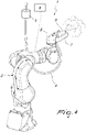
Figure 3 is a cross-section side view of the portion shown infigure 1 in a third operational configuration; -
Figure 4 is an axonometric view of a possible portion of the machine for filling bottles, cartridges, syringes and the like, according to the invention in a third operational configuration. - With specific reference to these figures, the
number 1 generally refers to a machine for filling bottles, cartridges, syringes and the like. Generally, themachine 1 can be suitable for carrying out all the procedures related to filling containers, such as bottles, cartridges, syringes, vials, carpules and the like. - These procedures may require cleaning each container, weighing (before and after filling), sealing (with specific caps or other means of closure) and the provision of fastening rings for the closure caps. It is already specified that the
machine 1 may also carry out just one of the procedures mentioned, as it may carry out other procedures, as required by the specific type of container that needs to be processed. Themachine 1, according to this invention, comprises a chamber with an inlet and outlet, through which the containers flow into the chamber; the chamber also comprises an intermediate operational area in which the containers are subjected to specific processing procedures, such as those listed above. - The
machine 1, according to this invention, comprises at least onehandling device 2 with several degrees of freedom, automatically controlled and reprogrammable. Thehandling device 2 is preferably secured to aframe 3 of themachine 1. - The
machine 1 also comprises at least oneconduit 4 for washing and sanitising fluids. - The
conduit 4 is entirely located outside of thehandling device 2 and has a dispensingnozzle 5 directly attached to its free end. - The technical advantages of this invention lie specifically in the fact that the dispensing
nozzle 5 is configured to be joined to anadjustable end 6 of thehandling device 2 for washing and sanitising the chamber and the containers contained therein. - In practice, the
conduit 4 is not even partially integrated in thehandling device 2, as theconduit 4 and the dispensingnozzle 5 are completely independent of the handling device. - Therefore, it is easy to change the
conduit 4 and type of dispensingnozzle 5 when necessary. It is therefore sufficient to join the dispensingnozzle 5 to theadjustable end 6 of thehandling device 2. Theconduit 4 is also easy to wash and replace, as it does not pass inside thehandling device 2. - With specific reference to a realistic and practical solution that can be applied, represented, by way of a non-limiting example, by the attached figures, the at least one
conduit 4 may include a flexible portion, protruding into the chamber. - According to the invention, the dispensing
nozzle 5 has shape and dimensions matching to those ofclamping elements 7 arranged at theadjustable end 6 of saidhandling device 2. I this way the dispensingnozzle 5 can be removed from theclamping elements 7 when required. - More specifically, it should be noted that the flexible portion of the
conduit 4 can be conveniently projected into the chamber through its upper wall (the ceiling of the chamber), from above thehandling device 2. - In this way, it will be possible to have
conduits 4 with a shorter flexible portion, thus reducing the overall costs and ensuring an optimal execution of washing and sanitising procedures. - According to an alternative solution, the
conduit 4 can run along the outer surface of thehandling device 2, ensuring that, in the articulated zone of thehandling device 2, appropriate joining elements are provided. - The
conduit 4 can comprise anautomatic valve units 8 for controlling the flow of washing and sanitising fluids. - In order to ensure the optimal operation of the
machine 1 according to the invention, at least onehandling device 2 and thevalve units 8 are controlled by a control andmanagement processor 9. - Optionally, the
handling device 2 can be coupled to at least two dispensingnozzles 5 attached directly to a free end of arespective conduit 4. In other words, there are a first conduit with a first dispensing nozzle and a second conduit with a second dispensing nozzle, both the first and the second dispensing nozzles are coupled to the sameadjustable end 6 of thehandling device 2. - In this way, it will also be possible to dispense the fluid into very wide, solid corner, so that the
handling device 2, by changing the direction of itsadjustable end 6, can easily supply a jet of liquid within the chamber. - By way of example, the washing and sanitising fluids can preferably be selected from water, water vapour, hydrogen peroxide, hydrogen peroxide vapours, solvents, solvent vapours, ozone-containing gas mixtures, liquid mixtures, gas mixtures and similar substances.
- In order to ensure that the
machine 1 can operate with any type of container, including containers received in a nest, it should be noted that thehandling device 2 can preferably be an anthropomorphic robot. - Anthropomorphic robots are highly versatile and allow for very simple change-over procedures, such as, for example, by merely reprogramming their work cycles.
- At the same time, it should be noted that some anthropomorphic robots are equipped with appropriate sensors that also enable self-learning, further simplifying the start-up and execution of the procedures required by the
machine 1 according to this invention. Advantageously, this invention resolves the problems outlined at the beginning, by providing amachine 1 for filling bottles, cartridges, syringes and the like, suitable for automatically performing cleaning and sanitising procedures, without the need for staff to intervene. Effectively, themachine 1 for filling bottles, cartridges, syringes and the like does not require any access to the chamber by instruments, tools and/or staff to carry out cleaning and sanitising procedures, as it can be automatically controlled. - Conveniently, the
machine 1, according to this invention, allows for short-term cleaning procedures to be carried out, which can be performed on a regular basis, without requiring long machine shut-down times. - This invention effectively provides a
machine 1 for filling bottles, cartridges, syringes and the like, with a relatively simple, practical and cost-effective procedure: these features make themachine 1, according to this invention, a safe-to-use innovation.
Claims (9)
- Machine for filling bottles, cartridges, syringes and the like, generally defined as containers, the machine comprising a chamber with an inlet and outlet for containers and at least one intermediate operating station in which the containers are subjected to specific processing, further comprising at least one handling device (2) with several degrees of freedom, automatically controlled and reprogrammable and at least one conduit (4) for washing and sanitising fluids, and a dispensing nozzle (5) attached directly to a free end of the conduit (4), said dispensing nozzle (5) being configured to be joined to an adjustable end (6) of the at least one handling device (2) for washing and sanitising said chamber and the containers contained therein; characterized in that
said at least one conduit (4) is entirely located outside of said handling device (2) and in that it has a flexible portion protruding inside said chamber, said dispensing nozzle (5) having shape and dimensions matching to those of clamping elements (7) arranged at the adjustable end (6) of said handling device (2), so that a removable coupling between said dispensing nozzle (5) and said clamping elements (7) is achieved. - Machine according to claim 1, wherein said flexible portion of the conduit (4) protrudes into said chamber from an upper wall of the chamber, from above the handling device (2).
- Machine according to any one of the preceding claims, wherein the at least one conduit (4) is stably coupled to the handling device (2), with said dispensing nozzle (5) joined to the adjustable end (6) of said handling device (2).
- Machine according to any one of the preceding claims, wherein at least one conduit (4) comprises an automatic valve unit (8) for controlling the flow of washing and sanitising fluids.
- Machine according to claim 4, wherein the at least one handling device (2) and said valve units (8) are controlled by a control and management processor (9).
- Machine according to any one of the preceding claims, wherein the least one handling device (2) is coupled to at least two dispensing nozzles (5) attached directly to a free end of a respective conduits (4).
- Machine according to any one of the preceding claims, wherein said washing and sanitising fluids are selected from water, water vapour, hydrogen peroxide, hydrogen peroxide vapours, solvents, solvent vapours, ozone-containing gas mixtures, liquid mixtures, gas mixtures and similar substances.
- Machine according to any one of the preceding claims, wherein the at least one handling device (2) is an anthropomorphic robot.
- Machine according to any one the preceding claims, wherein said handling device (6) is secured to a frame (3) of the machine (1).
Applications Claiming Priority (2)
| Application Number | Priority Date | Filing Date | Title |
|---|---|---|---|
| IT102016000078037A IT201600078037A1 (en) | 2016-07-26 | 2016-07-26 | MACHINE FOR FILLING BOTTLES, CARTRIDGES, SYRINGES AND THE LIKE |
| PCT/EP2017/068658 WO2018019775A1 (en) | 2016-07-26 | 2017-07-24 | Machine for filling bottles and the like comprising handling device for washing and sanitising |
Publications (2)
| Publication Number | Publication Date |
|---|---|
| EP3490732A1 EP3490732A1 (en) | 2019-06-05 |
| EP3490732B1 true EP3490732B1 (en) | 2022-08-31 |
Family
ID=57610161
Family Applications (1)
| Application Number | Title | Priority Date | Filing Date |
|---|---|---|---|
| EP17740418.3A Active EP3490732B1 (en) | 2016-07-26 | 2017-07-24 | Machine for filling bottles and the like comprising handling device for washing and sanitising |
Country Status (4)
| Country | Link |
|---|---|
| EP (1) | EP3490732B1 (en) |
| ES (1) | ES2929145T3 (en) |
| IT (1) | IT201600078037A1 (en) |
| WO (1) | WO2018019775A1 (en) |
Families Citing this family (2)
| Publication number | Priority date | Publication date | Assignee | Title |
|---|---|---|---|---|
| CN109866233B (en) * | 2019-03-06 | 2021-02-19 | 厦门驿创数字科技有限公司 | Archive management robot |
| WO2025259178A1 (en) * | 2024-06-14 | 2025-12-18 | Primech Ai Pte. Ltd. | A cleaning robot |
Citations (6)
| Publication number | Priority date | Publication date | Assignee | Title |
|---|---|---|---|---|
| EP0374586A1 (en) | 1988-12-21 | 1990-06-27 | Tetra Alfa Holdings S.A. | Washing and cleaning system on a packing machine |
| US5439649A (en) | 1993-09-29 | 1995-08-08 | Biogenex Laboratories | Automated staining apparatus |
| JP2008237112A (en) | 2007-03-27 | 2008-10-09 | Kawasaki Heavy Ind Ltd | Automatic cell culture device with drug spray gun |
| EP2218521A2 (en) | 2009-02-17 | 2010-08-18 | Jürgen Löhrke GmbH | Cleaning assembly |
| DE102010045269A1 (en) | 2010-09-14 | 2012-03-15 | Khs Gmbh | Washing and cleaning system for container treatment machines |
| JP2012116495A (en) | 2010-11-30 | 2012-06-21 | Kazuto Hanazono | Manufacturing device of medicinal product |
Family Cites Families (1)
| Publication number | Priority date | Publication date | Assignee | Title |
|---|---|---|---|---|
| DE202007006113U1 (en) * | 2007-04-26 | 2007-07-12 | Rst Regel- Und Steuerungsanlagen Gmbh | High pressure system for cleaning surfaces with high pressure fluid jet, comprises pressure conduit for adjusting volume flow rate in specified range, where pressure conduit with bent spiral section is arranged as metallic pressure pipe |
-
2016
- 2016-07-26 IT IT102016000078037A patent/IT201600078037A1/en unknown
-
2017
- 2017-07-24 WO PCT/EP2017/068658 patent/WO2018019775A1/en not_active Ceased
- 2017-07-24 ES ES17740418T patent/ES2929145T3/en active Active
- 2017-07-24 EP EP17740418.3A patent/EP3490732B1/en active Active
Patent Citations (6)
| Publication number | Priority date | Publication date | Assignee | Title |
|---|---|---|---|---|
| EP0374586A1 (en) | 1988-12-21 | 1990-06-27 | Tetra Alfa Holdings S.A. | Washing and cleaning system on a packing machine |
| US5439649A (en) | 1993-09-29 | 1995-08-08 | Biogenex Laboratories | Automated staining apparatus |
| JP2008237112A (en) | 2007-03-27 | 2008-10-09 | Kawasaki Heavy Ind Ltd | Automatic cell culture device with drug spray gun |
| EP2218521A2 (en) | 2009-02-17 | 2010-08-18 | Jürgen Löhrke GmbH | Cleaning assembly |
| DE102010045269A1 (en) | 2010-09-14 | 2012-03-15 | Khs Gmbh | Washing and cleaning system for container treatment machines |
| JP2012116495A (en) | 2010-11-30 | 2012-06-21 | Kazuto Hanazono | Manufacturing device of medicinal product |
Non-Patent Citations (3)
| Title |
|---|
| MERKMALSANALYSE ANSPRUCH 1 |
| PROSPEKT KAWASAKI ROBOTER MC/MS SERIE |
| SCREENSHOTS AUS YOUTUBE-VIDEO |
Also Published As
| Publication number | Publication date |
|---|---|
| WO2018019775A1 (en) | 2018-02-01 |
| CA3032009A1 (en) | 2018-02-01 |
| ES2929145T3 (en) | 2022-11-25 |
| IT201600078037A1 (en) | 2018-01-26 |
| EP3490732A1 (en) | 2019-06-05 |
Similar Documents
| Publication | Publication Date | Title |
|---|---|---|
| US8728249B2 (en) | Packing machine | |
| KR102615068B1 (en) | Apparatus and method for protecting and deprotecting fluid paths in controlled environment enclosures | |
| EP3033276B1 (en) | Method for filling pharmaceutical containers | |
| US12291364B2 (en) | Isolator system for filling a container with a liquid, transfer station for transferring a container and method therefor | |
| ES2785952T3 (en) | Opening set for a container | |
| CN100534891C (en) | Machine for aseptic treatment of containers in bottling plants | |
| US10858132B2 (en) | Disposable production line for filling and finishing a product | |
| KR102449042B1 (en) | Machines and processes for the preparation of intravenous pharmaceuticals | |
| EP3490732B1 (en) | Machine for filling bottles and the like comprising handling device for washing and sanitising | |
| US8613584B2 (en) | System and method for transferring and moving elements of an automatic packing machine | |
| JP2007276881A (en) | Disposable unit | |
| US12077330B2 (en) | Filling device for filling containers in a single-use isolator | |
| US11826308B2 (en) | Filling device for the dosed filling of a liquid or fine powdery product from a product storage container into product dose receiving containers provided in a disposable isolator so as to be protected against contamination | |
| CN108290649A (en) | The rotary filling device of aseptic filling for bag | |
| JP2012116495A (en) | Manufacturing device of medicinal product | |
| JP4329066B2 (en) | Sterility test sampling method and apparatus | |
| US9522818B2 (en) | Filling machine | |
| CA3032009C (en) | Machine for filling bottles and the like comprising handling device for washing and sanitising | |
| US20200338765A1 (en) | Disposable isolater and product conditioning installation comprising such a disposable installator | |
| US20150158057A1 (en) | Processing system for powders, and method for processing powders | |
| ES2989701T3 (en) | Apparatus for filling containers in a sterile environment | |
| IT201600078054A1 (en) | MACHINE FOR FILLING BOTTLES, CARTRIDGES, SYRINGES AND THE LIKE. | |
| JP7299490B2 (en) | Goods transport system | |
| KR20250069595A (en) | Method for sterilizing components of a machine that operates in a sterile closed environment and that is used for contact with products that are to be processed inside the closed environment | |
| IT202300022140A1 (en) | EQUIPMENT FOR FILLING A CONTAINER WITH A RESPECTIVE PRODUCT |
Legal Events
| Date | Code | Title | Description |
|---|---|---|---|
| STAA | Information on the status of an ep patent application or granted ep patent |
Free format text: STATUS: UNKNOWN |
|
| STAA | Information on the status of an ep patent application or granted ep patent |
Free format text: STATUS: THE INTERNATIONAL PUBLICATION HAS BEEN MADE |
|
| PUAI | Public reference made under article 153(3) epc to a published international application that has entered the european phase |
Free format text: ORIGINAL CODE: 0009012 |
|
| STAA | Information on the status of an ep patent application or granted ep patent |
Free format text: STATUS: REQUEST FOR EXAMINATION WAS MADE |
|
| 17P | Request for examination filed |
Effective date: 20190226 |
|
| AK | Designated contracting states |
Kind code of ref document: A1 Designated state(s): AL AT BE BG CH CY CZ DE DK EE ES FI FR GB GR HR HU IE IS IT LI LT LU LV MC MK MT NL NO PL PT RO RS SE SI SK SM TR |
|
| AX | Request for extension of the european patent |
Extension state: BA ME |
|
| DAV | Request for validation of the european patent (deleted) | ||
| DAX | Request for extension of the european patent (deleted) | ||
| GRAP | Despatch of communication of intention to grant a patent |
Free format text: ORIGINAL CODE: EPIDOSNIGR1 |
|
| STAA | Information on the status of an ep patent application or granted ep patent |
Free format text: STATUS: GRANT OF PATENT IS INTENDED |
|
| INTG | Intention to grant announced |
Effective date: 20220429 |
|
| GRAS | Grant fee paid |
Free format text: ORIGINAL CODE: EPIDOSNIGR3 |
|
| GRAA | (expected) grant |
Free format text: ORIGINAL CODE: 0009210 |
|
| STAA | Information on the status of an ep patent application or granted ep patent |
Free format text: STATUS: THE PATENT HAS BEEN GRANTED |
|
| AK | Designated contracting states |
Kind code of ref document: B1 Designated state(s): AL AT BE BG CH CY CZ DE DK EE ES FI FR GB GR HR HU IE IS IT LI LT LU LV MC MK MT NL NO PL PT RO RS SE SI SK SM TR |
|
| REG | Reference to a national code |
Ref country code: CH Ref legal event code: EP Ref country code: GB Ref legal event code: FG4D |
|
| REG | Reference to a national code |
Ref country code: AT Ref legal event code: REF Ref document number: 1514912 Country of ref document: AT Kind code of ref document: T Effective date: 20220915 Ref country code: DE Ref legal event code: R096 Ref document number: 602017061241 Country of ref document: DE |
|
| REG | Reference to a national code |
Ref country code: IE Ref legal event code: FG4D |
|
| REG | Reference to a national code |
Ref country code: ES Ref legal event code: FG2A Ref document number: 2929145 Country of ref document: ES Kind code of ref document: T3 Effective date: 20221125 |
|
| REG | Reference to a national code |
Ref country code: LT Ref legal event code: MG9D |
|
| REG | Reference to a national code |
Ref country code: NL Ref legal event code: MP Effective date: 20220831 |
|
| PG25 | Lapsed in a contracting state [announced via postgrant information from national office to epo] |
Ref country code: SE Free format text: LAPSE BECAUSE OF FAILURE TO SUBMIT A TRANSLATION OF THE DESCRIPTION OR TO PAY THE FEE WITHIN THE PRESCRIBED TIME-LIMIT Effective date: 20220831 Ref country code: RS Free format text: LAPSE BECAUSE OF FAILURE TO SUBMIT A TRANSLATION OF THE DESCRIPTION OR TO PAY THE FEE WITHIN THE PRESCRIBED TIME-LIMIT Effective date: 20220831 Ref country code: NO Free format text: LAPSE BECAUSE OF FAILURE TO SUBMIT A TRANSLATION OF THE DESCRIPTION OR TO PAY THE FEE WITHIN THE PRESCRIBED TIME-LIMIT Effective date: 20221130 Ref country code: LV Free format text: LAPSE BECAUSE OF FAILURE TO SUBMIT A TRANSLATION OF THE DESCRIPTION OR TO PAY THE FEE WITHIN THE PRESCRIBED TIME-LIMIT Effective date: 20220831 Ref country code: LT Free format text: LAPSE BECAUSE OF FAILURE TO SUBMIT A TRANSLATION OF THE DESCRIPTION OR TO PAY THE FEE WITHIN THE PRESCRIBED TIME-LIMIT Effective date: 20220831 Ref country code: FI Free format text: LAPSE BECAUSE OF FAILURE TO SUBMIT A TRANSLATION OF THE DESCRIPTION OR TO PAY THE FEE WITHIN THE PRESCRIBED TIME-LIMIT Effective date: 20220831 |
|
| REG | Reference to a national code |
Ref country code: AT Ref legal event code: MK05 Ref document number: 1514912 Country of ref document: AT Kind code of ref document: T Effective date: 20220831 |
|
| PG25 | Lapsed in a contracting state [announced via postgrant information from national office to epo] |
Ref country code: PL Free format text: LAPSE BECAUSE OF FAILURE TO SUBMIT A TRANSLATION OF THE DESCRIPTION OR TO PAY THE FEE WITHIN THE PRESCRIBED TIME-LIMIT Effective date: 20220831 Ref country code: IS Free format text: LAPSE BECAUSE OF FAILURE TO SUBMIT A TRANSLATION OF THE DESCRIPTION OR TO PAY THE FEE WITHIN THE PRESCRIBED TIME-LIMIT Effective date: 20221231 Ref country code: HR Free format text: LAPSE BECAUSE OF FAILURE TO SUBMIT A TRANSLATION OF THE DESCRIPTION OR TO PAY THE FEE WITHIN THE PRESCRIBED TIME-LIMIT Effective date: 20220831 Ref country code: GR Free format text: LAPSE BECAUSE OF FAILURE TO SUBMIT A TRANSLATION OF THE DESCRIPTION OR TO PAY THE FEE WITHIN THE PRESCRIBED TIME-LIMIT Effective date: 20221201 |
|
| PG25 | Lapsed in a contracting state [announced via postgrant information from national office to epo] |
Ref country code: SM Free format text: LAPSE BECAUSE OF FAILURE TO SUBMIT A TRANSLATION OF THE DESCRIPTION OR TO PAY THE FEE WITHIN THE PRESCRIBED TIME-LIMIT Effective date: 20220831 Ref country code: RO Free format text: LAPSE BECAUSE OF FAILURE TO SUBMIT A TRANSLATION OF THE DESCRIPTION OR TO PAY THE FEE WITHIN THE PRESCRIBED TIME-LIMIT Effective date: 20220831 Ref country code: PT Free format text: LAPSE BECAUSE OF FAILURE TO SUBMIT A TRANSLATION OF THE DESCRIPTION OR TO PAY THE FEE WITHIN THE PRESCRIBED TIME-LIMIT Effective date: 20230102 Ref country code: DK Free format text: LAPSE BECAUSE OF FAILURE TO SUBMIT A TRANSLATION OF THE DESCRIPTION OR TO PAY THE FEE WITHIN THE PRESCRIBED TIME-LIMIT Effective date: 20220831 Ref country code: CZ Free format text: LAPSE BECAUSE OF FAILURE TO SUBMIT A TRANSLATION OF THE DESCRIPTION OR TO PAY THE FEE WITHIN THE PRESCRIBED TIME-LIMIT Effective date: 20220831 Ref country code: AT Free format text: LAPSE BECAUSE OF FAILURE TO SUBMIT A TRANSLATION OF THE DESCRIPTION OR TO PAY THE FEE WITHIN THE PRESCRIBED TIME-LIMIT Effective date: 20220831 |
|
| REG | Reference to a national code |
Ref country code: DE Ref legal event code: R026 Ref document number: 602017061241 Country of ref document: DE |
|
| PG25 | Lapsed in a contracting state [announced via postgrant information from national office to epo] |
Ref country code: SK Free format text: LAPSE BECAUSE OF FAILURE TO SUBMIT A TRANSLATION OF THE DESCRIPTION OR TO PAY THE FEE WITHIN THE PRESCRIBED TIME-LIMIT Effective date: 20220831 Ref country code: EE Free format text: LAPSE BECAUSE OF FAILURE TO SUBMIT A TRANSLATION OF THE DESCRIPTION OR TO PAY THE FEE WITHIN THE PRESCRIBED TIME-LIMIT Effective date: 20220831 |
|
| PLBI | Opposition filed |
Free format text: ORIGINAL CODE: 0009260 |
|
| P01 | Opt-out of the competence of the unified patent court (upc) registered |
Effective date: 20230426 |
|
| PLAX | Notice of opposition and request to file observation + time limit sent |
Free format text: ORIGINAL CODE: EPIDOSNOBS2 |
|
| PG25 | Lapsed in a contracting state [announced via postgrant information from national office to epo] |
Ref country code: NL Free format text: LAPSE BECAUSE OF FAILURE TO SUBMIT A TRANSLATION OF THE DESCRIPTION OR TO PAY THE FEE WITHIN THE PRESCRIBED TIME-LIMIT Effective date: 20220831 Ref country code: AL Free format text: LAPSE BECAUSE OF FAILURE TO SUBMIT A TRANSLATION OF THE DESCRIPTION OR TO PAY THE FEE WITHIN THE PRESCRIBED TIME-LIMIT Effective date: 20220831 |
|
| 26 | Opposition filed |
Opponent name: GROSSE VON HIRSCHHAUSEN PATENTDIENST GMBH Effective date: 20230531 Opponent name: FOCKE & CO. (GMBH & CO. KG) Effective date: 20230525 |
|
| PG25 | Lapsed in a contracting state [announced via postgrant information from national office to epo] |
Ref country code: SI Free format text: LAPSE BECAUSE OF FAILURE TO SUBMIT A TRANSLATION OF THE DESCRIPTION OR TO PAY THE FEE WITHIN THE PRESCRIBED TIME-LIMIT Effective date: 20220831 |
|
| PLBB | Reply of patent proprietor to notice(s) of opposition received |
Free format text: ORIGINAL CODE: EPIDOSNOBS3 |
|
| PG25 | Lapsed in a contracting state [announced via postgrant information from national office to epo] |
Ref country code: MC Free format text: LAPSE BECAUSE OF FAILURE TO SUBMIT A TRANSLATION OF THE DESCRIPTION OR TO PAY THE FEE WITHIN THE PRESCRIBED TIME-LIMIT Effective date: 20220831 |
|
| PG25 | Lapsed in a contracting state [announced via postgrant information from national office to epo] |
Ref country code: MC Free format text: LAPSE BECAUSE OF FAILURE TO SUBMIT A TRANSLATION OF THE DESCRIPTION OR TO PAY THE FEE WITHIN THE PRESCRIBED TIME-LIMIT Effective date: 20220831 |
|
| REG | Reference to a national code |
Ref country code: BE Ref legal event code: MM Effective date: 20230731 |
|
| PG25 | Lapsed in a contracting state [announced via postgrant information from national office to epo] |
Ref country code: LU Free format text: LAPSE BECAUSE OF NON-PAYMENT OF DUE FEES Effective date: 20230724 |
|
| PG25 | Lapsed in a contracting state [announced via postgrant information from national office to epo] |
Ref country code: LU Free format text: LAPSE BECAUSE OF NON-PAYMENT OF DUE FEES Effective date: 20230724 |
|
| REG | Reference to a national code |
Ref country code: IE Ref legal event code: MM4A |
|
| PG25 | Lapsed in a contracting state [announced via postgrant information from national office to epo] |
Ref country code: BE Free format text: LAPSE BECAUSE OF NON-PAYMENT OF DUE FEES Effective date: 20230731 |
|
| PG25 | Lapsed in a contracting state [announced via postgrant information from national office to epo] |
Ref country code: IE Free format text: LAPSE BECAUSE OF NON-PAYMENT OF DUE FEES Effective date: 20230724 |
|
| PG25 | Lapsed in a contracting state [announced via postgrant information from national office to epo] |
Ref country code: IE Free format text: LAPSE BECAUSE OF NON-PAYMENT OF DUE FEES Effective date: 20230724 |
|
| PG25 | Lapsed in a contracting state [announced via postgrant information from national office to epo] |
Ref country code: BG Free format text: LAPSE BECAUSE OF FAILURE TO SUBMIT A TRANSLATION OF THE DESCRIPTION OR TO PAY THE FEE WITHIN THE PRESCRIBED TIME-LIMIT Effective date: 20220831 |
|
| PG25 | Lapsed in a contracting state [announced via postgrant information from national office to epo] |
Ref country code: BG Free format text: LAPSE BECAUSE OF FAILURE TO SUBMIT A TRANSLATION OF THE DESCRIPTION OR TO PAY THE FEE WITHIN THE PRESCRIBED TIME-LIMIT Effective date: 20220831 |
|
| APAH | Appeal reference modified |
Free format text: ORIGINAL CODE: EPIDOSCREFNO |
|
| APBP | Date of receipt of notice of appeal recorded |
Free format text: ORIGINAL CODE: EPIDOSNNOA2O |
|
| APBQ | Date of receipt of statement of grounds of appeal recorded |
Free format text: ORIGINAL CODE: EPIDOSNNOA3O |
|
| PG25 | Lapsed in a contracting state [announced via postgrant information from national office to epo] |
Ref country code: CY Free format text: LAPSE BECAUSE OF FAILURE TO SUBMIT A TRANSLATION OF THE DESCRIPTION OR TO PAY THE FEE WITHIN THE PRESCRIBED TIME-LIMIT; INVALID AB INITIO Effective date: 20170724 |
|
| PG25 | Lapsed in a contracting state [announced via postgrant information from national office to epo] |
Ref country code: HU Free format text: LAPSE BECAUSE OF FAILURE TO SUBMIT A TRANSLATION OF THE DESCRIPTION OR TO PAY THE FEE WITHIN THE PRESCRIBED TIME-LIMIT; INVALID AB INITIO Effective date: 20170724 |
|
| PGFP | Annual fee paid to national office [announced via postgrant information from national office to epo] |
Ref country code: ES Payment date: 20250827 Year of fee payment: 9 |
|
| PGFP | Annual fee paid to national office [announced via postgrant information from national office to epo] |
Ref country code: DE Payment date: 20250723 Year of fee payment: 9 |
|
| PGFP | Annual fee paid to national office [announced via postgrant information from national office to epo] |
Ref country code: IT Payment date: 20250722 Year of fee payment: 9 |
|
| PGFP | Annual fee paid to national office [announced via postgrant information from national office to epo] |
Ref country code: GB Payment date: 20250724 Year of fee payment: 9 |
|
| PGFP | Annual fee paid to national office [announced via postgrant information from national office to epo] |
Ref country code: FR Payment date: 20250717 Year of fee payment: 9 |
|
| PGFP | Annual fee paid to national office [announced via postgrant information from national office to epo] |
Ref country code: CH Payment date: 20250801 Year of fee payment: 9 |
|
| PG25 | Lapsed in a contracting state [announced via postgrant information from national office to epo] |
Ref country code: TR Free format text: LAPSE BECAUSE OF FAILURE TO SUBMIT A TRANSLATION OF THE DESCRIPTION OR TO PAY THE FEE WITHIN THE PRESCRIBED TIME-LIMIT Effective date: 20220831 |