EP3490627B1 - System for reducing gaseous microemboli using venous blood bypass with filter - Google Patents
System for reducing gaseous microemboli using venous blood bypass with filter Download PDFInfo
- Publication number
- EP3490627B1 EP3490627B1 EP17837451.8A EP17837451A EP3490627B1 EP 3490627 B1 EP3490627 B1 EP 3490627B1 EP 17837451 A EP17837451 A EP 17837451A EP 3490627 B1 EP3490627 B1 EP 3490627B1
- Authority
- EP
- European Patent Office
- Prior art keywords
- oxygenator
- fluid
- flow
- blood
- sweep gas
- Prior art date
- Legal status (The legal status is an assumption and is not a legal conclusion. Google has not performed a legal analysis and makes no representation as to the accuracy of the status listed.)
- Active
Links
- 210000004369 blood Anatomy 0.000 title claims description 88
- 239000008280 blood Substances 0.000 title claims description 88
- 239000012530 fluid Substances 0.000 claims description 137
- 239000000835 fiber Substances 0.000 claims description 20
- 239000011148 porous material Substances 0.000 claims description 14
- 230000017531 blood circulation Effects 0.000 claims description 11
- 239000000126 substance Substances 0.000 claims description 11
- 239000012528 membrane Substances 0.000 claims description 8
- 239000012982 microporous membrane Substances 0.000 claims description 7
- FAPWRFPIFSIZLT-UHFFFAOYSA-M Sodium chloride Chemical compound [Na+].[Cl-] FAPWRFPIFSIZLT-UHFFFAOYSA-M 0.000 claims description 6
- 239000010836 blood and blood product Substances 0.000 claims description 6
- 229940125691 blood product Drugs 0.000 claims description 6
- 230000001419 dependent effect Effects 0.000 claims description 6
- 239000011780 sodium chloride Substances 0.000 claims description 6
- 102000009027 Albumins Human genes 0.000 claims description 4
- 108010088751 Albumins Proteins 0.000 claims description 4
- 229920001612 Hydroxyethyl starch Polymers 0.000 claims description 4
- 239000002473 artificial blood Substances 0.000 claims description 4
- 239000003633 blood substitute Substances 0.000 claims description 4
- BPKIGYQJPYCAOW-FFJTTWKXSA-I calcium;potassium;disodium;(2s)-2-hydroxypropanoate;dichloride;dihydroxide;hydrate Chemical compound O.[OH-].[OH-].[Na+].[Na+].[Cl-].[Cl-].[K+].[Ca+2].C[C@H](O)C([O-])=O BPKIGYQJPYCAOW-FFJTTWKXSA-I 0.000 claims description 4
- 239000012141 concentrate Substances 0.000 claims description 4
- 229940027278 hetastarch Drugs 0.000 claims description 4
- 238000004891 communication Methods 0.000 claims description 3
- 238000009792 diffusion process Methods 0.000 claims description 3
- 239000012510 hollow fiber Substances 0.000 claims description 3
- 239000007789 gas Substances 0.000 description 125
- IJGRMHOSHXDMSA-UHFFFAOYSA-N Atomic nitrogen Chemical compound N#N IJGRMHOSHXDMSA-UHFFFAOYSA-N 0.000 description 30
- 238000000034 method Methods 0.000 description 30
- QVGXLLKOCUKJST-UHFFFAOYSA-N atomic oxygen Chemical compound [O] QVGXLLKOCUKJST-UHFFFAOYSA-N 0.000 description 29
- 239000001301 oxygen Substances 0.000 description 29
- 229910052760 oxygen Inorganic materials 0.000 description 29
- CURLTUGMZLYLDI-UHFFFAOYSA-N Carbon dioxide Chemical compound O=C=O CURLTUGMZLYLDI-UHFFFAOYSA-N 0.000 description 23
- 230000036961 partial effect Effects 0.000 description 17
- 229910052757 nitrogen Inorganic materials 0.000 description 15
- 229910002092 carbon dioxide Inorganic materials 0.000 description 14
- 102000029749 Microtubule Human genes 0.000 description 10
- 108091022875 Microtubule Proteins 0.000 description 10
- 210000004688 microtubule Anatomy 0.000 description 10
- 239000001569 carbon dioxide Substances 0.000 description 9
- 229940079593 drug Drugs 0.000 description 8
- 239000003814 drug Substances 0.000 description 8
- 239000000203 mixture Substances 0.000 description 7
- 239000002245 particle Substances 0.000 description 7
- 238000006213 oxygenation reaction Methods 0.000 description 6
- 230000009467 reduction Effects 0.000 description 6
- 238000013459 approach Methods 0.000 description 5
- 230000004087 circulation Effects 0.000 description 5
- 239000000463 material Substances 0.000 description 5
- 230000001706 oxygenating effect Effects 0.000 description 5
- 238000012545 processing Methods 0.000 description 5
- 239000003146 anticoagulant agent Substances 0.000 description 4
- 229940127219 anticoagulant drug Drugs 0.000 description 4
- -1 e.g. Substances 0.000 description 4
- 239000006260 foam Substances 0.000 description 4
- 238000005259 measurement Methods 0.000 description 4
- 229920000642 polymer Polymers 0.000 description 4
- XLYOFNOQVPJJNP-UHFFFAOYSA-N water Substances O XLYOFNOQVPJJNP-UHFFFAOYSA-N 0.000 description 4
- 206010002091 Anaesthesia Diseases 0.000 description 3
- 230000037005 anaesthesia Effects 0.000 description 3
- 230000015572 biosynthetic process Effects 0.000 description 3
- 230000002612 cardiopulmonary effect Effects 0.000 description 3
- 238000001914 filtration Methods 0.000 description 3
- 230000006870 function Effects 0.000 description 3
- 210000000056 organ Anatomy 0.000 description 3
- 239000000243 solution Substances 0.000 description 3
- 238000001356 surgical procedure Methods 0.000 description 3
- MYMOFIZGZYHOMD-UHFFFAOYSA-N Dioxygen Chemical compound O=O MYMOFIZGZYHOMD-UHFFFAOYSA-N 0.000 description 2
- 239000003570 air Substances 0.000 description 2
- 238000004458 analytical method Methods 0.000 description 2
- 230000036772 blood pressure Effects 0.000 description 2
- 230000000747 cardiac effect Effects 0.000 description 2
- 230000001413 cellular effect Effects 0.000 description 2
- 230000015271 coagulation Effects 0.000 description 2
- 238000005345 coagulation Methods 0.000 description 2
- 239000000084 colloidal system Substances 0.000 description 2
- 238000011973 continuous veno-venous hemofiltration Methods 0.000 description 2
- 230000000694 effects Effects 0.000 description 2
- 239000000499 gel Substances 0.000 description 2
- 238000005534 hematocrit Methods 0.000 description 2
- 230000000222 hyperoxic effect Effects 0.000 description 2
- 239000010410 layer Substances 0.000 description 2
- 230000000670 limiting effect Effects 0.000 description 2
- 230000007246 mechanism Effects 0.000 description 2
- 230000007107 neurocognitive deficit Effects 0.000 description 2
- 239000003921 oil Substances 0.000 description 2
- 230000001737 promoting effect Effects 0.000 description 2
- 230000002829 reductive effect Effects 0.000 description 2
- 238000005070 sampling Methods 0.000 description 2
- 230000002792 vascular Effects 0.000 description 2
- OKTJSMMVPCPJKN-UHFFFAOYSA-N Carbon Chemical compound [C] OKTJSMMVPCPJKN-UHFFFAOYSA-N 0.000 description 1
- 208000017667 Chronic Disease Diseases 0.000 description 1
- 206010053567 Coagulopathies Diseases 0.000 description 1
- 102000000429 Factor XII Human genes 0.000 description 1
- 108010080865 Factor XII Proteins 0.000 description 1
- 206010019280 Heart failures Diseases 0.000 description 1
- 102000001554 Hemoglobins Human genes 0.000 description 1
- 108010054147 Hemoglobins Proteins 0.000 description 1
- 206010061218 Inflammation Diseases 0.000 description 1
- 102000004895 Lipoproteins Human genes 0.000 description 1
- 108090001030 Lipoproteins Proteins 0.000 description 1
- 241000124008 Mammalia Species 0.000 description 1
- 241001465754 Metazoa Species 0.000 description 1
- 239000004743 Polypropylene Substances 0.000 description 1
- 208000035965 Postoperative Complications Diseases 0.000 description 1
- 208000001647 Renal Insufficiency Diseases 0.000 description 1
- 208000002847 Surgical Wound Diseases 0.000 description 1
- 230000004913 activation Effects 0.000 description 1
- 230000002411 adverse Effects 0.000 description 1
- 230000000740 bleeding effect Effects 0.000 description 1
- 210000004556 brain Anatomy 0.000 description 1
- 229910052799 carbon Inorganic materials 0.000 description 1
- 210000005242 cardiac chamber Anatomy 0.000 description 1
- 238000007675 cardiac surgery Methods 0.000 description 1
- 230000035602 clotting Effects 0.000 description 1
- 230000000295 complement effect Effects 0.000 description 1
- 239000000470 constituent Substances 0.000 description 1
- 230000006378 damage Effects 0.000 description 1
- 238000001514 detection method Methods 0.000 description 1
- 238000000502 dialysis Methods 0.000 description 1
- 230000010339 dilation Effects 0.000 description 1
- 238000010790 dilution Methods 0.000 description 1
- 239000012895 dilution Substances 0.000 description 1
- 238000004090 dissolution Methods 0.000 description 1
- 229920001971 elastomer Polymers 0.000 description 1
- 210000003038 endothelium Anatomy 0.000 description 1
- 238000011156 evaluation Methods 0.000 description 1
- 238000002618 extracorporeal membrane oxygenation Methods 0.000 description 1
- 238000000338 in vitro Methods 0.000 description 1
- 238000001727 in vivo Methods 0.000 description 1
- 230000004054 inflammatory process Effects 0.000 description 1
- 230000002401 inhibitory effect Effects 0.000 description 1
- 208000028867 ischemia Diseases 0.000 description 1
- 201000006370 kidney failure Diseases 0.000 description 1
- 210000000265 leukocyte Anatomy 0.000 description 1
- 150000002632 lipids Chemical class 0.000 description 1
- 239000007788 liquid Substances 0.000 description 1
- 210000004072 lung Anatomy 0.000 description 1
- 238000012423 maintenance Methods 0.000 description 1
- 238000013178 mathematical model Methods 0.000 description 1
- 238000002483 medication Methods 0.000 description 1
- 239000002184 metal Substances 0.000 description 1
- 238000012544 monitoring process Methods 0.000 description 1
- 238000007911 parenteral administration Methods 0.000 description 1
- 230000010412 perfusion Effects 0.000 description 1
- 230000035699 permeability Effects 0.000 description 1
- 239000004033 plastic Substances 0.000 description 1
- 229920000728 polyester Polymers 0.000 description 1
- 229920001155 polypropylene Polymers 0.000 description 1
- 230000002980 postoperative effect Effects 0.000 description 1
- 230000005180 public health Effects 0.000 description 1
- 230000002685 pulmonary effect Effects 0.000 description 1
- 230000009103 reabsorption Effects 0.000 description 1
- 230000007115 recruitment Effects 0.000 description 1
- 201000004193 respiratory failure Diseases 0.000 description 1
- 230000002441 reversible effect Effects 0.000 description 1
- 229920006395 saturated elastomer Polymers 0.000 description 1
- 239000002344 surface layer Substances 0.000 description 1
- 210000001519 tissue Anatomy 0.000 description 1
- 238000002054 transplantation Methods 0.000 description 1
- 238000009564 veno-arterial ECMO Methods 0.000 description 1
- 238000009565 veno-venous ECMO Methods 0.000 description 1
- 230000002861 ventricular Effects 0.000 description 1
- 239000001993 wax Substances 0.000 description 1
Images


Classifications
-
- A—HUMAN NECESSITIES
- A61—MEDICAL OR VETERINARY SCIENCE; HYGIENE
- A61M—DEVICES FOR INTRODUCING MEDIA INTO, OR ONTO, THE BODY; DEVICES FOR TRANSDUCING BODY MEDIA OR FOR TAKING MEDIA FROM THE BODY; DEVICES FOR PRODUCING OR ENDING SLEEP OR STUPOR
- A61M1/00—Suction or pumping devices for medical purposes; Devices for carrying-off, for treatment of, or for carrying-over, body-liquids; Drainage systems
- A61M1/36—Other treatment of blood in a by-pass of the natural circulatory system, e.g. temperature adaptation, irradiation ; Extra-corporeal blood circuits
- A61M1/3621—Extra-corporeal blood circuits
- A61M1/3627—Degassing devices; Buffer reservoirs; Drip chambers; Blood filters
-
- A—HUMAN NECESSITIES
- A61—MEDICAL OR VETERINARY SCIENCE; HYGIENE
- A61M—DEVICES FOR INTRODUCING MEDIA INTO, OR ONTO, THE BODY; DEVICES FOR TRANSDUCING BODY MEDIA OR FOR TAKING MEDIA FROM THE BODY; DEVICES FOR PRODUCING OR ENDING SLEEP OR STUPOR
- A61M1/00—Suction or pumping devices for medical purposes; Devices for carrying-off, for treatment of, or for carrying-over, body-liquids; Drainage systems
- A61M1/14—Dialysis systems; Artificial kidneys; Blood oxygenators ; Reciprocating systems for treatment of body fluids, e.g. single needle systems for hemofiltration or pheresis
- A61M1/16—Dialysis systems; Artificial kidneys; Blood oxygenators ; Reciprocating systems for treatment of body fluids, e.g. single needle systems for hemofiltration or pheresis with membranes
- A61M1/1698—Blood oxygenators with or without heat-exchangers
-
- A—HUMAN NECESSITIES
- A61—MEDICAL OR VETERINARY SCIENCE; HYGIENE
- A61M—DEVICES FOR INTRODUCING MEDIA INTO, OR ONTO, THE BODY; DEVICES FOR TRANSDUCING BODY MEDIA OR FOR TAKING MEDIA FROM THE BODY; DEVICES FOR PRODUCING OR ENDING SLEEP OR STUPOR
- A61M1/00—Suction or pumping devices for medical purposes; Devices for carrying-off, for treatment of, or for carrying-over, body-liquids; Drainage systems
- A61M1/36—Other treatment of blood in a by-pass of the natural circulatory system, e.g. temperature adaptation, irradiation ; Extra-corporeal blood circuits
- A61M1/3621—Extra-corporeal blood circuits
- A61M1/3623—Means for actively controlling temperature of blood
-
- A—HUMAN NECESSITIES
- A61—MEDICAL OR VETERINARY SCIENCE; HYGIENE
- A61M—DEVICES FOR INTRODUCING MEDIA INTO, OR ONTO, THE BODY; DEVICES FOR TRANSDUCING BODY MEDIA OR FOR TAKING MEDIA FROM THE BODY; DEVICES FOR PRODUCING OR ENDING SLEEP OR STUPOR
- A61M1/00—Suction or pumping devices for medical purposes; Devices for carrying-off, for treatment of, or for carrying-over, body-liquids; Drainage systems
- A61M1/36—Other treatment of blood in a by-pass of the natural circulatory system, e.g. temperature adaptation, irradiation ; Extra-corporeal blood circuits
- A61M1/3621—Extra-corporeal blood circuits
- A61M1/3666—Cardiac or cardiopulmonary bypass, e.g. heart-lung machines
-
- A—HUMAN NECESSITIES
- A61—MEDICAL OR VETERINARY SCIENCE; HYGIENE
- A61M—DEVICES FOR INTRODUCING MEDIA INTO, OR ONTO, THE BODY; DEVICES FOR TRANSDUCING BODY MEDIA OR FOR TAKING MEDIA FROM THE BODY; DEVICES FOR PRODUCING OR ENDING SLEEP OR STUPOR
- A61M2205/00—General characteristics of the apparatus
- A61M2205/33—Controlling, regulating or measuring
- A61M2205/3331—Pressure; Flow
- A61M2205/3334—Measuring or controlling the flow rate
-
- A—HUMAN NECESSITIES
- A61—MEDICAL OR VETERINARY SCIENCE; HYGIENE
- A61M—DEVICES FOR INTRODUCING MEDIA INTO, OR ONTO, THE BODY; DEVICES FOR TRANSDUCING BODY MEDIA OR FOR TAKING MEDIA FROM THE BODY; DEVICES FOR PRODUCING OR ENDING SLEEP OR STUPOR
- A61M2205/00—General characteristics of the apparatus
- A61M2205/75—General characteristics of the apparatus with filters
- A61M2205/7545—General characteristics of the apparatus with filters for solid matter, e.g. microaggregates
Definitions
- the disclosure relates to a system and method for cardiopulmonary bypass, and more particularly to a system and method to reduce gaseous microemboli (GME) using an oxygenator with venous bypass and a filter.
- GME gaseous microemboli
- Gas bubbles are easily formed in blood and are propelled into the circulation of a living being during extracorporeal circulation. Gas bubbles are formed from many sources, including cavitation, temperature gradients, and differences in the amount of gases dissolved between a subject's own and incoming blood, as well as inadvertent physical introduction of gas bubbles into blood by caregivers during surgical manipulation or parenteral administration of fluids.
- the extracorporeal circuit contains a gas-exchange device, for example an oxygenator, which is used for oxygenation and removal of carbon dioxide, for example.
- the close contact between blood and gas in the oxygenator poses significant risks for inadvertent entry of gas bubbles into the circulating blood.
- Heart-lung machines contain an air bubble sensor that warns the person controlling the heart-lung machine of the appearance of small bubbles, and immediately stops the main pump when larger bubbles appear.
- the bubble sensor can discern bubbles with a diameter of approximately 0.3 millimeters (mm) or larger, and stops the main pump when a bubble with a diameter of 3-5 mm is recognized.
- GME gaseous microemboli
- CPB cardiopulmonary bypass
- WO 03/066134 discloses a filter apparatus, which includes a blood processing unit 21 (e.g., filter, heat exchanger), a filter apparatus 30, a suction source 34, a gas removal element 40, and a blood processing component 31 ("conventional blood processing unit 31 may contain an extracorporeal blood oxygenation system having a blood reservoir, an oxygenator, a pump and a pump motor").
- the venous line 11 carries deoxygenated blood from patient P into the system.
- the flow of fluid through the apparatus is directed through the gas removal element 21 and/or gas removal element 40 and directly into the blood processing unit 31 (including the oxygenator), i.e., in series.
- the flow of fluid is not divided in two portions, one of which is diverted to the gas removal element, the other one being diverted to the blood processing unit.
- U.S. 2012/0277654 discloses a combination oxygenator and arterial filter device for treating blood in an extracorporeal circuit includes a housing, an oxygenator, and a depth filter.
- Fig. 2A is an example of the disclosed arterial filter device, and includes a blood entrance of inlet 70 for directing blood flow into the device, an oxygenator 34 including an internal core 38 and an oxygenator bundle 40, and the arterial depth filter 36 within a housing 32.
- blood enters the apparatus via the inlet 70, passes through the oxygenator 34 and then into the arterial depth filter 36.
- Blood flow through the oxygenator and filter occurs in series, and not in parallel. Blood flow is not divided in two portions, one of which is diverted to the oxygenator, the other one being diverted to the filter.
- U.S. 2013/0296633 discloses a system for oxygenating blood, in which a supply of blood is supplied to a first branch and a second branch.
- the first branch leads to an external blood oxygenator, which oxygenates the blood and returns the blood to the circulatory system.
- the second branch bypasses the oxygenator and connects to the circulatory system of the subject. While blood is supplied to the second branch, the oxygenator may be disconnected and blood prevented from entering the first branch.
- D3 does not disclose a filter in either the first or second branch or an output which combines the fluid from the first and second branches.
- GME gaseous microemboli
- CPB cardiopulmonary bypass
- a system for reducing gaseous microemboli comprising a fluid source 10; a flow diverter fluidly connected to the fluid source, an oxygenator fluidly connected to the flow diverter, wherein the oxygenator is configured to oxygenate the fluid from the fluid source; a bypass line or a non-gas exchange shunt channel through the oxygenator fluidly connected to the flow diverter; an inflow flow controller fluidly connected to the fluid source and to the flow diverter, wherein the inflow flow controller is between the fluid source and the flow diverter and is configured to control the flow rate of fluid from the fluid source to the flow diverter, wherein the flow diverter is configured to divert a portion of the fluid from the fluid source to the oxygenator and another portion of the fluid from the fluid source to the bypass line or to the non-gas exchange shunt channel through the oxygenator; a filter in fluid communication with the bypass line or the non-gas exchange shunt channel, wherein the filter removes gaseous microemboli from the fluid in the bypass line or the non-gas exchange s
- the inventor hereof has unexpectedly solved the practical problem of shunting of GME around an oxygenator, by using an arterial filter in the shunt limb, in an embodiment.
- This disclosure is directed to reduction of GME during CPB and other procedures including extracorporeal membrane oxygenation (ECMO), including veno-arterial ECMO and veno-venous ECMO, by the use of an oxygenator with venous blood bypass and a filter in the venous blood bypass.
- ECMO extracorporeal membrane oxygenation
- the systems and methods described can also be used for extracorporeal circulation systems including dialysis, continuous veno-venous hemofiltration (CVVH), and heart ventricular assist devices (VAD).
- Venous blood bypass takes a portion of the blood from the venous system or other source of non-oxygenated blood, bypasses the oxygenator, and introduces the bypassed venous blood into blood coming from the oxygenator.
- This mixture of oxygenated and non-oxygenated blood reduces the concentration of oxygen in the blood coming from the oxygenator, promoting removal of microbubbles from the blood.
- This approach allows the operation of the oxygenator using pure oxygen, nitrogen-free sweep gas, thereby avoiding both hyperoxemia that may be damaging to the patient and dissolved nitrogen that may oppose dissolution and removal of microbubbles
- the gas profile in the mixed arterial blood traveling to the patient is around 150-250 mmHg dissolved oxygen (around 100 mmHg is the normal value in a healthy human) plus around 40 mmHg dissolved CO 2 , for a sum of partial pressures of dissolved gases of 190-290 mmHg, which is hypobaric compared to the approximately 760 mmHg atmospheric pressure.
- emboli with diameter larger than a stated pore size of a filter for example, between 15 to 50 micrometers, for example, greater than 15 micrometers, greater than 20 micrometers, greater than 28 micrometers, greater than 32 micrometers, greater than 37 micrometers, or greater than 40 micrometers, for example, are removed, and particles having a diameter less than the stated pore size pass through.
- emboli having diameter larger than 50 micrometers, preferably larger than 40 micrometers, preferably larger than 28 micrometers are removed from the filtered circuit. Emboli in this size range are considered large enough to occlude capillaries but small enough to pass through an arterial filter.
- fluid and blood are used interchangeably, except as otherwise noted. It is to be understood that the systems and methods can be used for blood, or other fluids, such as a blood substitute, artificial blood, a blood product, such as plasma or albumin, platelets or plasma concentrates, crystalloids such as saline, lactated ringer's solution, normosol, plasmalyte, hetastarch, or other fluid, or a combination comprising at least one of the foregoing.
- a blood substitute such as a blood substitute, artificial blood, a blood product, such as plasma or albumin, platelets or plasma concentrates, crystalloids such as saline, lactated ringer's solution, normosol, plasmalyte, hetastarch, or other fluid, or a combination comprising at least one of the foregoing.
- a blood substitute such as plasma or albumin
- platelets or plasma concentrates such as crystalloids such as saline, lactated ringer's solution, normosol,
- the fluid source can be from a subject, such as an animal, for example a human, or other mammal.
- the fluid source can be from a subject using cannulae inserted into the subject's venous or arterial system or heart chambers or body cavities, a fluid reservoir, or from a source outside a subject.
- the subject can be a patient undergoing treatment or evaluation.
- the filter because it acts as a resistance to flow, can be used to adjust or control flow in the bypass line.
- a flow diverter is used to divert a portion of the blood and can be any suitable apparatus used to remove a portion of the fluid from the fluid source, such as a tubing tee, or a pump, or a separate non-gas-exchange shunt channel through an oxygenator.
- a separate non-gas-exchange shunt channel through an oxygenator can use 1) a filtered or non-filtered shunt channel within the oxygenator itself, the flow through which may or may not be regulatable or user-determined; or 2) a means of flowing sweep gas selectively to only a fraction of the sweep gas microtubules in the oxygenator fiber bundle, thereby allowing non-gas-exchange shunting to occur within the oxygenator without defeating the oxygenator's filtration role, for example.
- This approach can use a variable flap or device comprised of rubber, gel, polymer, foam, wax, plastic, metal, or other suitable material or reversible occlusion device to prevent gas flow through a portion of the fiber bundle near the sweep gas inlet or within the sweep gas inlet manifold, near the sweep gas outlet or within the sweep gas outlet manifold, or both, or anywhere along the sweep gas flow path.
- a variable flap or device comprised of rubber, gel, polymer, foam, wax, plastic, metal, or other suitable material or reversible occlusion device to prevent gas flow through a portion of the fiber bundle near the sweep gas inlet or within the sweep gas inlet manifold, near the sweep gas outlet or within the sweep gas outlet manifold, or both, or anywhere along the sweep gas flow path.
- There can be more than one occlusion device used in a device, and a user or controller may be able to engage them in a desired combination to produce the desired amount of non-gas-exchange shunting.
- the occlusion may also be performed using a fluid or other suitable substance instilled into the sweep gas inlet manifold, or sweep gas outlet manifold, or both, for example water, oil, polymer, foam, or wax, 2b)
- a fluid or other suitable substance such as water, saline, crystalloid, colloid, blood product, oil, gel, polymer, foam, or wax instilled permanently or reversibly into the sweep gas inlet manifold or the sealed or unsealed sweep gas outlet manifold, or both, in order to prevent flow through a fraction of the sweep gas microtubules of the fiber bundle.
- Extra ports in dependent or non-dependent portions of the sweep gas inlet manifold or the sweep gas outlet manifold, or both, may be required to allow instillation and removal of substances to regulate sweep gas flow in the fiber bundle.
- Positive pressure relief valves in the sweep gas inlet manifold or the sweep gas outlet manifold, or both, may be required to relieve positive pressures that may result from limitation of sweep gas flow to a fraction of the fiber bundle.
- a non-gas-exchange shunt channel through an oxygenator can also be performed by dividing the oxygenator into compartments or using multiple oxygenators, where each compartment or oxygenator receives blood flow but the user can decide whether and how much sweep gas to flow in some of the compartments or oxygenators to achieve the desired level of non-gas-exchange shunting.
- the same desirable effects on dissolved gases in blood and GME removal may be achieved in the absence of non-gas exchange shunting by directing blood and sweep gas flow to a minimum number of compartments or oxygenators necessary to achieve a user-defined oxygenation target but no more.
- the amount and flow characteristics of the fluid coming from the fluid source can be controlled by an inflow controller, such as a needle valve, a mass flow controller, pump, or partial occlusion clamp.
- the inflow controller can be controlled independently, or can be controlled by a controller configured to control other aspects of the system, as described further herein.
- the bypass line can be any suitable material, such as medical grade tubing, or other materials known to one of ordinary skill in the art without undue experimentation.
- the diameter, length, and composition of the bypass line is easily determined by one of ordinary skill in the art without undue experimentation.
- the flow of fluid in the bypass line can be further controlled, for example to achieve the desired characteristics of fluid in the outlet.
- a sensor can be used in any desirable or useful location in the system to determine the actual or approximate number and size of GME or other particles, concentration of anticoagulants, anesthesia, or other medication, concentration of gases, such as oxygen, nitrogen, carbon dioxide, oxygen saturation of blood hemoglobin, or flow rate, for example.
- Flow rate and oxygen saturation sensors are applied external to the tubing and are standard. Blood samples are removed frequently, and in some cases continuously, for more detailed blood gas and anticoagulant analysis.
- the composition or other characteristics of the fluid in the bypass line can be altered from the composition or other characteristics of the fluid in the fluid source.
- medication such as anticoagulants or other medication
- gases such as oxygen, nitrogen, carbon dioxide, or air, for example, can be added or removed to achieve the desired level of gases and other components.
- a sensor is introduced at a location in the bypass line before the filter, a location in the bypass line after the filter, or a combination comprising one or more of the foregoing, to achieve the desired level of oxygen and other substances in the fluid in the bypass line.
- a filter is inserted in the bypass line.
- the filter can be a so-called “arterial filter”, as known in the art, designed to remove bubbles (GME), lipids, and other debris having a diameter greater than a stated pore size, for example, greater than 15 micrometers, greater than 20 micrometers, greater than 28 micrometers, greater than 32 micrometers, greater than 37 micrometers, or greater than 40 micrometers, for example, and let particles having a diameter less than the stated pore size pass through.
- GME bubbles
- lipids lipids
- other debris having a diameter greater than a stated pore size, for example, greater than 15 micrometers, greater than 20 micrometers, greater than 28 micrometers, greater than 32 micrometers, greater than 37 micrometers, or greater than 40 micrometers, for example, and let particles having a diameter less than the stated pore size pass through.
- the filter pore size should be small enough to remove bubbles, but not so small as to prevent desired blood flows at reasonable pressures, known to one of ordinary skill in the art, or cause damage or filtering of cellular elements.
- the filter can also be a hemoconcentrator, bubble trap, or oxygenator, any of which may be operated under vacuum.
- the filter can be made from any suitable material, such as polyester.
- the oxygenator can be any of a number of devices, such as a membrane oxygenator, a diffusion membrane oxygenator, or a hollow fiber microporous membrane oxygenator.
- the oxygenator is a microporous membrane oxygenator with or preferably without a sealed housing.
- the oxygenator is a microporous membrane oxygenator without a sealed housing.
- the connections of the fluid to and from the oxygenator, to and from the bypass line, and other connections are those known by one of ordinary skill in the art without undue experimentation.
- the operation of the oxygenator is known by one of ordinary skill in the art without undue experimentation.
- a flow controller can be a needle valve, a mass flow controller, a pump, a clamp, or a partial occlusion clamp.
- An outlet is fluidly connected to the oxygenator and the bypass line.
- the outlet can be the point where the fluid from the bypass line and the oxygenator are combined.
- a sensor can be used to measure a desired characteristic of the fluid at the outlet, for example, the concentration of anticoagulants or other medication, concentration of gases, such as oxygen, nitrogen, carbon dioxide, air, or blood oxygen saturation.
- the fluid After the fluid is passed through the oxygenator and combined with the fluid from the venous bypass, the fluid can be stored, or reinfused into a subject or patient, for example.
- Parameters of the system can be controlled by a controller, configured to control the inflow flow controller, the bypass flow controller, the outflow flow controller, or a combination comprising at least one or more of the foregoing.
- a controller configured to control the inflow flow controller, the bypass flow controller, the outflow flow controller, or a combination comprising at least one or more of the foregoing.
- Each of the parameters of the system can also be controlled independently, such as by use of a manual valve.
- 0 to 50 percent of the total volume of the blood coming from the patient into the CPB system is diverted to the venous bypass. In an embodiment, 0 to 40 percent of the total volume of the blood coming from the patient into the CPB system is diverted to the venous bypass. In an embodiment, 0 to 30 percent of the total volume of the blood coming from the patient into the CPB system is diverted to the venous bypass. In an embodiment, 0 to 20 percent of the total volume of the blood coming from the patient into the CPB system is diverted to the venous bypass. In an embodiment, 0 to 10 percent of the total volume of the blood coming from the patient into the CPB system is diverted to the venous bypass.
- the partial pressure of oxygen at the outlet is 50 to 800 mmHg. In an embodiment, the partial pressure of oxygen at the outlet is 100 to 700 mmHg. In an embodiment, the partial pressure of oxygen at the outlet is 75 to 650 mmHg. In an embodiment, the partial pressure of nitrogen at the outlet is zero. In an embodiment, the partial pressure of nitrogen at the outlet is minimized. In an embodiment, the partial pressure of nitrogen at the outlet is a nonzero level up to about 600 mmHg.
- the desired parameters/composition of blood or fluid at the outlet depends on the goals of the surgical team and perfusionist for the patient. Frequently, the perfusionist will target an oxygen tension of 150-250 mmHg, a CO 2 tension of 40 mmHg, and an overall flow rate that is reasonably close to the patient's predicted normal cardiac output and which generates an adequate blood pressure in the patient's vascular system.
- the perfusionist may flow 5L/min of total flow, comprised of 1.5L/min of flow through the shunt limb and 3.5L/min of flow through the oxygenator. He or she may raise or lower the shunt fraction to adjust the pO 2 , raise or lower the sweep gas flow rate to adjust the pCO 2 , or raise or lower the flow rate to adjust the blood pressure.
- the filter acts to remove gaseous microemboli, as well as acts as a flow restrictor for the venous blood bypass, which can be used to control the oxygen level of the blood going back to the patient, for example.
- the method can be used in both normal baric and hypobaric conditions.
- the oxygenator is configured to have a subatmospheric pressure, and can have a pressure of 0.4 to 1 atmospheres absolute.
- the described shunt can be used together with operating an oxygenator at subatmospheric pressure.
- the system includes a vacuum regulator fluidly connected to the oxygenator, and configured to provide the subatmospheric pressure.
- the oxygenator is configured to have atmospheric pressure.
- the system can include one or more sensors configured to measure one or more of flow rate, fluid composition, oxygen saturation, carbon dioxide content, nitrogen content, temperature, hematocrit, or a combination comprising one or more of the foregoing, wherein the sensor is fluidly connected to the fluid source, the bypass line, the outlet, or a combination comprising one or more of the foregoing.
- sensors can be any of a number of common sensors, known to one of ordinary skill in the art.
- the controller comprises a processor and software instructions implemented by the processor.
- the fluid source can be a blender configured to combine one or more fluids.
- the system can be used for a number of different fluids, such as blood, a blood substitute, artificial blood, a blood product, such as plasma or albumin, platelets or plasma concentrates, crystalloids such as saline, lactated ringer's solution, normosol, plasmalyte, hetastarch, or other fluid, or a combination comprising one or more of the foregoing.
- fluids such as blood, a blood substitute, artificial blood, a blood product, such as plasma or albumin, platelets or plasma concentrates, crystalloids such as saline, lactated ringer's solution, normosol, plasmalyte, hetastarch, or other fluid, or a combination comprising one or more of the foregoing.
- a method for reducing gaseous microemboli including providing an oxygenator configured to oxygenate a fluid, the oxygenator having a venous inlet, an arterial outlet; a venous bypass line fluidly connected to the venous inlet and the arterial outlet, wherein the venous bypass line comprises a filter configured to remove gaseous microemboli greater than a stated pore size, typically 15 to 50 micrometers, or 28 to 40 micrometers, for example, and wherein the venous bypass line is configured to remove a portion of the fluid from the venous inlet; introducing a fluid to the oxygenator; oxygenating the fluid passing through the oxygenator, typically using pure oxygen sweep gas; combining the fluid from the venous bypass line and the arterial outlet, forming a combined fluid; wherein the concentration of oxygen in the combined fluid is 75 to 800 mmHg, preferably 100 to 700 mmHg, preferably 100 to 650 mmHg, preferably 150 to 250 mmHg.
- the oxygenator can be any suitable apparatus that can introduce oxygen to a fluid and remove carbon dioxide from a fluid.
- the method can further include introducing medication or gases into the fluid.
- the method can further include measuring the concentration of oxygen, nitrogen, carbon dioxide, anesthesia, medication, oxygen saturation, or other substances at any point including the blood and the gas at the sweep gas outlet.
- the measuring can be performed using any suitable measurement apparatus or sampling technique, such as the use of an inline dual-wavelength oximeter, or the use of a sampling technique where a portion of the fluid is removed for analysis.
- the method can further include monitoring or controlling the temperature of the fluid at any point.
- the system and method can also include a non-gas-exchange shunt channel through the oxygenator, instead of, or in addition to the shunt limb.
- a non-gas-exchange shunt channel through the oxygenator or the shunt limb is used.
- a non-gas-exchange shunt channel through the oxygenator is used.
- the non-gas-exchange shunt channel can be a filtered shunt flow channel within the oxygenator, wherein the flow rate through the filtered shunt flow channel is optionally regulatable.
- the oxygenator can be fluidly connected to a sweep gas reservoir or source via a sweep gas inlet and a sweep gas outlet, wherein the oxygenator comprises sweep gas microtubules in a fiber bundle, and the non-gas-exchange shunt channel comprises a means of flowing sweep gas selectively to a fraction of the sweep gas microtubules in the oxygenator fiber bundle, wherein non-gas-exchange shunting occurs within the oxygenator.
- the oxygenator is fluidly connected to a sweep gas reservoir via a sweep gas inlet and a sweep gas outlet, and the means of flowing sweep gas selectively to a fraction of the sweep gas microtubules in the oxygenator fiber bundle comprises a variable flow flap or occlusion device, wherein the variable flow flap or occlusion device prevents gas flow through a portion of the fiber bundle near the sweep gas inlet, near the sweep gas outlet, or both, or anywhere along the flow path of the fluid from the fluid source.
- the oxygenator comprises two or more compartments, wherein the flow of sweep gas in each compartment is independently adjustable.
- each oxygenator can be fluidly connected to a sweep gas reservoir via a sweep gas inlet and a sweep gas outlet, and each oxygenator can receive fluid from the fluid source, and the flow of sweep gas to each oxygenator is independently adjustable.
- the oxygenator comprises two or more compartments
- blood flow to each compartment is independently adjustable so that blood flow may be withheld from some compartments to use only as much oxygenating capacity as necessary to achieve the target level of dissolved oxygen and no more.
- blood flow to each oxygenator is independently adjustable so that blood flow may be withheld from some oxygenators to use only as much oxygenating capacity as necessary to achieve the target level of dissolved oxygen and no more.
- the partial pressure of nitrogen at the outlet is reduced or minimized compared with standard oxygenation strategies incorporating air.
- the system and method can be used with any CPB system or circuit, including the system described in WO2015/047927 .
- Figure 1 shows a schematic of an exemplary embodiment of a system using venous bypass with a filter to reduce GME.
- Fluid which can be gas, liquid, dissolved gas, or a combination comprising one or more of the foregoing
- optional inflow flow controller 20 which controls the flow rate, amount, and other characteristics of fluid from fluid source 10 into flow diverter 30.
- Optional inflow flow controller 20 can be a pump in a CPB circuit.
- the bypass and outflow flow controllers, elements 60 and 70, are also optional.
- Optional controller 90 can control inflow flow controller 20, bypass flow controller 60 and/or outflow flow controller 70.
- Flow diverter 30 can be any of a number of suitable embodiments, such as a tee for diverting a fluid stream into two or more paths, a valve, or other suitable device. Fluid from flow diverter 30 passes into oxygenator 40 and bypass line 100. The percentage of fluid from fluid source 10 that passes into oxygenator 40 and bypass line 100 can vary, depending on a number of factors, including the amount of a desired substance such as oxygen, or other substance in outlet 80, the desired fluid volume at outlet 80, or other factors.
- Oxygenator 40 can be any of a number of apparatus or systems useful for adding oxygen to a fluid and removing carbon dioxide.
- Bypass line 100 includes filter 50. Filter 50 can be a so-called "arterial filter", typically used in CPB to reduce the number and size of GME.
- Filter 50 can be a screen filter where a filter medium having a desired pore size, as described elsewhere herein, is used to remove particles larger than the pore size of the filter medium.
- Filter 50 can be a depth filter, where a filter has a thickness where larger particles are trapped in the surface layers, while smaller particles are trapped by succeeding layers.
- the desired pore size or filter thickness can be varied, to remove or reduce the number of particles having a selected size.
- a screen filter can be used where the filter medium has a pore size of 50 micrometers, 40 micrometers, 25 micrometers, 15 micrometers, or other size that removes GME, but does not filter white blood cells or other desired blood constituents, or does not restrict the flow so that the needed or desired flow rate cannot be achieved.
- the filter accommodates adequate flow rates.
- the volume, flow rate, or other parameters of fluid from filter 50 can be controlled by bypass flow controller 60.
- the volume, flow rate, or other parameters of fluid from oxygenator 40 can be controlled by outflow flow controller 70. Fluid from bypass line 100 and oxygenator 40 are combined at outlet 80.
- Parameters of the fluid such as concentration of oxygen, nitrogen, carbon dioxide, anesthesia, medication, or other substance can be measured and adjusted at any point, as described herein.
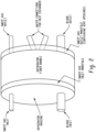
- FIG. 2 illustrates an exemplary oxygenator that can be used.
- the oxygenator is shown with a housing, a blood inlet and blood outlet, a sweep gas inlet and outlet, and a sweep gas inlet manifold and sweep gas outlet manifold (containing vent openings).
- the oxygenator is shown having a fiber bundle. Water connectors for heat exchange are also shown.
- the oxygenator can use any suitable membrane, such as polypropylene. Gas vents can be used to control the pressure of the oxygenator.
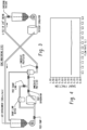
- Figure 3 shows a heart-lung machine circuit used for the data provided here.
- a CPB bypass circuit with Emboli Detection and Classification (EDAC) and venous air entrainment sites (500 mL/minute) is shown.
- FIG 4 shows experimental data showing that addition of a filter (Terumo AF125x) to the shunt limb ("shunt limb device" in Figure 3 , for example) effectively limits the shunt fraction to a safe level, and that this level is stable over a wide range of CPB flow rates.
- a filter Tuumo AF125x
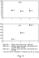
- Figure 5 provides experimental data showing that a filtered shunt in the heart-lung machine reduces dissolved O 2 in arterial blood to a safe, mildly hyperoxic, level like that targeted by perfusionists during CPB.
- the sweep gases were free of nitrogen, so the demonstrated levels of dissolved O 2 and CO 2 represent the only dissolved gases in the blood.
- Figure 5 provides data for three conditions, measurement of the pCO 2 and pO 2 in venous blood from the patient simulator (Condition 1); measurement of the pCO 2 and pO 2 in arterial blood from the heart-lung machine with the filtered shunt in place (Condition 2); and measurement of the pCO 2 and pO 2 in arterial blood from the heart-lung machine with no shunt (Condition 3).
- the Y-axes are partial pressures of dissolved CO 2 or Oz in mmHg.
- the X-axes are the conditions described above.
- Figure 6 provides experimental data showing reduction of GME before (upper graph titled “Pre Arterial Line Filter”) and after the arterial line filter (lower graph titled “Post Arterial Line Filter”) when using a filtered shunt compared to control (no shunt).
- the reduction of GME after the arterial line filter is measured downstream of the oxygenator/filtered shunt in question and on the way to the patient.
- control no shunt
- filtered filtered shunt
- y-axes are emboli per minute
- x-axes are emboli diameter in micrometers.
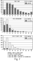
- Figure 7 provides experimental data showing GME at three locations in the CPB bypass circuit: post pump, post oxygenator, and at the end of the shunt limb (referred to as "Post Shunt Limb” in Figure 3 ).
- control non-filtered shunt
- filtered filtered shunt
- y-axes represent emboli per minute
- x-axes represent emboli diameter.
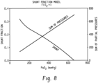
- Figure 8 shows a mathematical model of the sum of the partial pressures as a function of the shunt fraction.
- system for reducing gaseous microemboli comprising a fluid source; a flow diverter fluidly connected to the fluid source, wherein the flow diverter is configured to remove a portion of the fluid from the fluid source; an inflow flow controller fluidly connected to the fluid source, wherein the inflow flow controller is configured to control the flow rate of fluid from the fluid source to the flow diverter; a bypass line fluidly connected to the flow diverter; a bypass flow controller fluidly connected to the bypass line, wherein the bypass flow controller is configured to control the flow rate of fluid from the bypass line; a filter in fluid communication with the bypass line, wherein the filter removes gaseous microemboli having a diameter greater than a stated pore size, preferably 15 to 50 micrometers; an oxygenator fluidly connected to the fluid source, wherein the oxygenator is configured to oxygenate the fluid from the fluid source; an outflow flow controller fluidly connected to the oxygenator, wherein the outflow flow controller is configured to control the flow rate of fluid from the oxygenator; an outlet
- Also disclosed is a method for reducing gaseous microemboli comprising providing an oxygenator configured to oxygenate a fluid, the oxygenator having a venous inlet, an arterial outlet; a venous bypass line fluidly connected to the venous inlet and the arterial outlet, wherein the venous bypass line comprises a filter configured to remove gaseous microemboli having a diameter greater than a stated pore size, preferably 15 to 50 micrometers, and wherein the venous bypass line is configured to remove a portion of the fluid from the venous inlet; introducing a fluid to the oxygenator; oxygenating the fluid passing through the oxygenator; combining the fluid from the venous bypass line and the arterial outlet, forming a combined fluid; wherein the concentration of oxygen in the combined fluid is 100 to 700 mmHg, preferably 150 to 250 mmHg.
- Such method is not part of the subject matter for which protection is sought.
- the oxygenator is configured to have a subatmospheric pressure; and/or further comprising a vacuum regulator fluidly connected to the oxygenator, and configured to provide the subatmospheric pressure; and/or the oxygenator is configured to have atmospheric pressure; and/or further comprising a sensor configured to measure one or more of flow rate, fluid composition, blood oxygen saturation, oxygen tension, carbon tension fraction, nitrogen tension, hematocrit, or a combination comprising one or more of the foregoing, wherein the sensor is fluidly connected to the fluid source, the bypass line, the outlet, or a combination comprising one or more of the foregoing; and/or the controller comprises a processor and software instructions implemented by the processor; and/or the oxygenator is a membrane oxygenator, a diffusion membrane oxygenator, or a hollow fiber microporous membrane oxygenator; and/or the oxygenator is a microporous membrane oxygenator with a sealed housing; and/or the fluid is blood, a blood substitute, artificial blood, a blood product
Description
- The disclosure relates to a system and method for cardiopulmonary bypass, and more particularly to a system and method to reduce gaseous microemboli (GME) using an oxygenator with venous bypass and a filter. The disclosed methods do not fall under the claimed invention.
- There is a need to replace the function of the heart and lungs by artificial means, such as during heart operations. Also in more chronic disease states, for example during severe pulmonary, cardiac, or renal failure, maintenance of life can be upheld by different artificial means until an organ for transplantation becomes available. In many clinical situations there is a need for an extracorporeal circuit wherein an artificial organ is incorporated.
- Gas bubbles are easily formed in blood and are propelled into the circulation of a living being during extracorporeal circulation. Gas bubbles are formed from many sources, including cavitation, temperature gradients, and differences in the amount of gases dissolved between a subject's own and incoming blood, as well as inadvertent physical introduction of gas bubbles into blood by caregivers during surgical manipulation or parenteral administration of fluids. In the case of heart surgery, the extracorporeal circuit contains a gas-exchange device, for example an oxygenator, which is used for oxygenation and removal of carbon dioxide, for example. The close contact between blood and gas in the oxygenator poses significant risks for inadvertent entry of gas bubbles into the circulating blood.
- At present, to avoid bubble formation during heart surgery, membrane-type oxygenators are used instead of bubble-oxygenators, high temperature gradients are avoided, and use of suction in the operating field is controlled. Heart-lung machines contain an air bubble sensor that warns the person controlling the heart-lung machine of the appearance of small bubbles, and immediately stops the main pump when larger bubbles appear. Typically, the bubble sensor can discern bubbles with a diameter of approximately 0.3 millimeters (mm) or larger, and stops the main pump when a bubble with a diameter of 3-5 mm is recognized.
- Cardiac surgery is frequently complicated by postoperative neurocognitive deficits that degrade functional capacity and quality of life while increasing healthcare costs. Multifactorial contributors to this significant public health problem likely include gaseous microemboli (GME). The arterial circulation receives thousands of 10-40 micrometer (µm) diameter GME during cardiopulmonary bypass (CPB), despite the use of membrane oxygenation and arterial filtration. Vasooclusive GME cause tissue ischemia and denude endothelium in the brain and other end organs, leading to vascular dilation, increased permeability, activation of platelets and clotting cascades, and recruitment of complement and cellular mediators of inflammation.
- Current perfusion practice targets mildly hyperoxic blood gases during CPB, by lowering the partial pressure of oxygen in oxygenator sweep gas by dilution with air, thereby producing the needless side effect of dissolving nitrogen in blood. The blood, thus saturated with dissolved gas, is poorly able to dissolve gases that exist in bubble form as GME.
- Nonetheless, there remains a need to prevent or reduce the generation of gas bubbles, e.g., the formation of gas bubbles during heart surgery. In a blood bubble, in the liquid-gas interface, there is an approximately 40-100 Angstroms (Å) (4-10 nanometer) deep layer of lipoproteins that denaturate due to direct contact with the foreign material, e.g., gas. In turn, the Hageman factor is activated, which initiates coagulation and the concomitant adverse consumption of factors promoting coagulation, which are used to prevent bleeding from the surgical wound.
- Accordingly, a system and method capable of inhibiting the bubble formation in the blood, as well as reducing the number and size of bubbles during extracorporeal circulation, is needed.
-
WO 03/066134 filter apparatus 30, a suction source 34, agas removal element 40, and a blood processing component 31 ("conventional blood processing unit 31 may contain an extracorporeal blood oxygenation system having a blood reservoir, an oxygenator, a pump and a pump motor"). The venous line 11 carries deoxygenated blood from patient P into the system. The flow of fluid through the apparatus is directed through the gas removal element 21 and/orgas removal element 40 and directly into the blood processing unit 31 (including the oxygenator), i.e., in series. The flow of fluid is not divided in two portions, one of which is diverted to the gas removal element, the other one being diverted to the blood processing unit. -
U.S. 2012/0277654 discloses a combination oxygenator and arterial filter device for treating blood in an extracorporeal circuit includes a housing, an oxygenator, and a depth filter. Fig. 2A is an example of the disclosed arterial filter device, and includes a blood entrance ofinlet 70 for directing blood flow into the device, an oxygenator 34 including an internal core 38 and anoxygenator bundle 40, and the arterial depth filter 36 within a housing 32. As illustrated in Fig. 2A, blood enters the apparatus via theinlet 70, passes through the oxygenator 34 and then into the arterial depth filter 36. Blood flow through the oxygenator and filter occurs in series, and not in parallel. Blood flow is not divided in two portions, one of which is diverted to the oxygenator, the other one being diverted to the filter. -
U.S. 2013/0296633 discloses a system for oxygenating blood, in which a supply of blood is supplied to a first branch and a second branch. The first branch leads to an external blood oxygenator, which oxygenates the blood and returns the blood to the circulatory system. The second branch bypasses the oxygenator and connects to the circulatory system of the subject. While blood is supplied to the second branch, the oxygenator may be disconnected and blood prevented from entering the first branch. D3 does not disclose a filter in either the first or second branch or an output which combines the fluid from the first and second branches. - The invention is defined by the features of
independent claim 1. - The methods disclosed following do not fall under the claimed invention.
- Disclosed herein is a system and method for reducing gas bubbles, including gaseous microemboli (GME) during cardiopulmonary bypass (CPB). This approach reduces the number and size of GME, which can be useful in reducing postoperative complications, including neurocognitive deficits in CPB and other procedures. The system and method can be used for both in vitro and in vivo approaches. The system and method can be used in hypobaric and normobaric conditions.
- A system for reducing gaseous microemboli, the system comprising a
fluid source 10; a flow diverter fluidly connected to the fluid source, an oxygenator fluidly connected to the flow diverter, wherein the oxygenator is configured to oxygenate the fluid from the fluid source; a bypass line or a non-gas exchange shunt channel through the oxygenator fluidly connected to the flow diverter; an inflow flow controller fluidly connected to the fluid source and to the flow diverter, wherein the inflow flow controller is between the fluid source and the flow diverter and is configured to control the flow rate of fluid from the fluid source to the flow diverter, wherein the flow diverter is configured to divert a portion of the fluid from the fluid source to the oxygenator and another portion of the fluid from the fluid source to the bypass line or to the non-gas exchange shunt channel through the oxygenator; a filter in fluid communication with the bypass line or the non-gas exchange shunt channel, wherein the filter removes gaseous microemboli from the fluid in the bypass line or the non-gas exchange shunt channel, the gaseous microemboli having a diameter greater than a stated pore size; an outlet fluidly connected to the oxygenator and to the bypass line or the non-gas exchange shunt channel, and configured to combine the fluid from the bypass line and the oxygenator or from the non-gas exchange shunt channel and the oxygenator; and a controller configured to control the inflow flow controller, is provided. - The accompanying drawings incorporated in and forming a part of the specification embody several aspects of the present disclosure and, together with the description, serve to explain the principles of this disclosure. In the drawings:
-
Figure 1 is a schematic representation of an embodiment of a CPB system using a venous bypass with filter. -
Figure 2 is a schematic representation of an oxygenator that can be used. -
Figure 3 shows a heart-lung machine circuit used to obtain the data provided here. -
Figure 4 shows experimental data showing the fraction of total flow traveling through the shunt limb over a large range of total flow rates. -
Figure 5 shows experimental data showing the partial pressure of dissolved CO2 or O2 under three different conditions. -
Figure 6 shows experimental data showing reduction of GME at two locations in a CPB system. -
Figure 7 shows experimental data showing reduction of GME delivery through the shunt limb in the presence of an arterial filter at three locations in the CPB bypass circuit. -
Figure 8 shows the sum of the partial pressures as a function of the shunt fraction. - The following disclosure will detail particular exemplary embodiments, which provide methods and systems for reducing GME in a CPB system. The methods disclosed following do not fall under the claimed invention. An overview of the mechanism and methods used herein is provided.
- The inventor hereof has unexpectedly solved the practical problem of shunting of GME around an oxygenator, by using an arterial filter in the shunt limb, in an embodiment.
- This disclosure is directed to reduction of GME during CPB and other procedures including extracorporeal membrane oxygenation (ECMO), including veno-arterial ECMO and veno-venous ECMO, by the use of an oxygenator with venous blood bypass and a filter in the venous blood bypass. The systems and methods described can also be used for extracorporeal circulation systems including dialysis, continuous veno-venous hemofiltration (CVVH), and heart ventricular assist devices (VAD). Venous blood bypass takes a portion of the blood from the venous system or other source of non-oxygenated blood, bypasses the oxygenator, and introduces the bypassed venous blood into blood coming from the oxygenator. This mixture of oxygenated and non-oxygenated blood reduces the concentration of oxygen in the blood coming from the oxygenator, promoting removal of microbubbles from the blood. This approach allows the operation of the oxygenator using pure oxygen, nitrogen-free sweep gas, thereby avoiding both hyperoxemia that may be damaging to the patient and dissolved nitrogen that may oppose dissolution and removal of microbubbles
- Although Applicant is not bound by any theory presented here, it is believed the mechanism for reducing GME described here involves reducing the sum of partial pressures of dissolved gases in the arterial blood returning to the patient, thereby permitting reabsorption of gases from bubbles into the blood phase.
- In an embodiment, the gas profile in the mixed arterial blood traveling to the patient is around 150-250 mmHg dissolved oxygen (around 100 mmHg is the normal value in a healthy human) plus around 40 mmHg dissolved CO2, for a sum of partial pressures of dissolved gases of 190-290 mmHg, which is hypobaric compared to the approximately 760 mmHg atmospheric pressure.
- In an embodiment, all gas emboli, not matter how large or small, are removed in the filtered circuit. In an embodiment, emboli with diameter larger than a stated pore size of a filter, for example, between 15 to 50 micrometers, for example, greater than 15 micrometers, greater than 20 micrometers, greater than 28 micrometers, greater than 32 micrometers, greater than 37 micrometers, or greater than 40 micrometers, for example, are removed, and particles having a diameter less than the stated pore size pass through. In an embodiment, emboli having diameter larger than 50 micrometers, preferably larger than 40 micrometers, preferably larger than 28 micrometers are removed from the filtered circuit. Emboli in this size range are considered large enough to occlude capillaries but small enough to pass through an arterial filter.
- As used herein, "fluid" and "blood" are used interchangeably, except as otherwise noted. It is to be understood that the systems and methods can be used for blood, or other fluids, such as a blood substitute, artificial blood, a blood product, such as plasma or albumin, platelets or plasma concentrates, crystalloids such as saline, lactated ringer's solution, normosol, plasmalyte, hetastarch, or other fluid, or a combination comprising at least one of the foregoing.
- The fluid source can be from a subject, such as an animal, for example a human, or other mammal. The fluid source can be from a subject using cannulae inserted into the subject's venous or arterial system or heart chambers or body cavities, a fluid reservoir, or from a source outside a subject. The subject can be a patient undergoing treatment or evaluation.
- The filter, because it acts as a resistance to flow, can be used to adjust or control flow in the bypass line.
- A flow diverter is used to divert a portion of the blood and can be any suitable apparatus used to remove a portion of the fluid from the fluid source, such as a tubing tee, or a pump, or a separate non-gas-exchange shunt channel through an oxygenator.
- The use of a separate non-gas-exchange shunt channel through an oxygenator can use 1) a filtered or non-filtered shunt channel within the oxygenator itself, the flow through which may or may not be regulatable or user-determined; or 2) a means of flowing sweep gas selectively to only a fraction of the sweep gas microtubules in the oxygenator fiber bundle, thereby allowing non-gas-exchange shunting to occur within the oxygenator without defeating the oxygenator's filtration role, for example. 2a) This approach can use a variable flap or device comprised of rubber, gel, polymer, foam, wax, plastic, metal, or other suitable material or reversible occlusion device to prevent gas flow through a portion of the fiber bundle near the sweep gas inlet or within the sweep gas inlet manifold, near the sweep gas outlet or within the sweep gas outlet manifold, or both, or anywhere along the sweep gas flow path. There can be more than one occlusion device used in a device, and a user or controller may be able to engage them in a desired combination to produce the desired amount of non-gas-exchange shunting. The occlusion may also be performed using a fluid or other suitable substance instilled into the sweep gas inlet manifold, or sweep gas outlet manifold, or both, for example water, oil, polymer, foam, or wax, 2b) This approach may also use a fluid or other suitable substance such as water, saline, crystalloid, colloid, blood product, oil, gel, polymer, foam, or wax instilled permanently or reversibly into the sweep gas inlet manifold or the sealed or unsealed sweep gas outlet manifold, or both, in order to prevent flow through a fraction of the sweep gas microtubules of the fiber bundle. Extra ports in dependent or non-dependent portions of the sweep gas inlet manifold or the sweep gas outlet manifold, or both, may be required to allow instillation and removal of substances to regulate sweep gas flow in the fiber bundle. Positive pressure relief valves in the sweep gas inlet manifold or the sweep gas outlet manifold, or both, may be required to relieve positive pressures that may result from limitation of sweep gas flow to a fraction of the fiber bundle. 2c) A non-gas-exchange shunt channel through an oxygenator can also be performed by dividing the oxygenator into compartments or using multiple oxygenators, where each compartment or oxygenator receives blood flow but the user can decide whether and how much sweep gas to flow in some of the compartments or oxygenators to achieve the desired level of non-gas-exchange shunting.
- 3) In the case of an oxygenator employing multiple compartments or during the use of multiple oxygenators, the same desirable effects on dissolved gases in blood and GME removal may be achieved in the absence of non-gas exchange shunting by directing blood and sweep gas flow to a minimum number of compartments or oxygenators necessary to achieve a user-defined oxygenation target but no more. The amount and flow characteristics of the fluid coming from the fluid source, such as flow velocity, flow volume, or other characteristic into the flow diverter can be controlled by an inflow controller, such as a needle valve, a mass flow controller, pump, or partial occlusion clamp. The inflow controller can be controlled independently, or can be controlled by a controller configured to control other aspects of the system, as described further herein.
- The bypass line can be any suitable material, such as medical grade tubing, or other materials known to one of ordinary skill in the art without undue experimentation. The diameter, length, and composition of the bypass line is easily determined by one of ordinary skill in the art without undue experimentation.
- The flow of fluid in the bypass line can be further controlled, for example to achieve the desired characteristics of fluid in the outlet. A sensor can be used in any desirable or useful location in the system to determine the actual or approximate number and size of GME or other particles, concentration of anticoagulants, anesthesia, or other medication, concentration of gases, such as oxygen, nitrogen, carbon dioxide, oxygen saturation of blood hemoglobin, or flow rate, for example. Flow rate and oxygen saturation sensors are applied external to the tubing and are standard. Blood samples are removed frequently, and in some cases continuously, for more detailed blood gas and anticoagulant analysis. The composition or other characteristics of the fluid in the bypass line can be altered from the composition or other characteristics of the fluid in the fluid source. For example, medication, such as anticoagulants or other medication, or gases, such as oxygen, nitrogen, carbon dioxide, or air, for example, can be added or removed to achieve the desired level of gases and other components.
- In embodiments, a sensor is introduced at a location in the bypass line before the filter, a location in the bypass line after the filter, or a combination comprising one or more of the foregoing, to achieve the desired level of oxygen and other substances in the fluid in the bypass line.
- A filter is inserted in the bypass line. The filter can be a so-called "arterial filter", as known in the art, designed to remove bubbles (GME), lipids, and other debris having a diameter greater than a stated pore size, for example, greater than 15 micrometers, greater than 20 micrometers, greater than 28 micrometers, greater than 32 micrometers, greater than 37 micrometers, or greater than 40 micrometers, for example, and let particles having a diameter less than the stated pore size pass through.
- The filter pore size should be small enough to remove bubbles, but not so small as to prevent desired blood flows at reasonable pressures, known to one of ordinary skill in the art, or cause damage or filtering of cellular elements. The filter can also be a hemoconcentrator, bubble trap, or oxygenator, any of which may be operated under vacuum. The filter can be made from any suitable material, such as polyester.
- The oxygenator can be any of a number of devices, such as a membrane oxygenator, a diffusion membrane oxygenator, or a hollow fiber microporous membrane oxygenator. In an embodiment, the oxygenator is a microporous membrane oxygenator with or preferably without a sealed housing. In an embodiment, the oxygenator is a microporous membrane oxygenator without a sealed housing. The connections of the fluid to and from the oxygenator, to and from the bypass line, and other connections are those known by one of ordinary skill in the art without undue experimentation. The operation of the oxygenator is known by one of ordinary skill in the art without undue experimentation.
- The flow rate and volume, as well as other desired characteristics, of a fluid at any point in the system can be controlled by a flow controller, or other suitable device. A flow controller can be a needle valve, a mass flow controller, a pump, a clamp, or a partial occlusion clamp.
- An outlet is fluidly connected to the oxygenator and the bypass line. The outlet can be the point where the fluid from the bypass line and the oxygenator are combined. A sensor can be used to measure a desired characteristic of the fluid at the outlet, for example, the concentration of anticoagulants or other medication, concentration of gases, such as oxygen, nitrogen, carbon dioxide, air, or blood oxygen saturation.
- After the fluid is passed through the oxygenator and combined with the fluid from the venous bypass, the fluid can be stored, or reinfused into a subject or patient, for example.
- Parameters of the system can be controlled by a controller, configured to control the inflow flow controller, the bypass flow controller, the outflow flow controller, or a combination comprising at least one or more of the foregoing. Each of the parameters of the system can also be controlled independently, such as by use of a manual valve.
- In an embodiment, 0 to 50 percent of the total volume of the blood coming from the patient into the CPB system is diverted to the venous bypass. In an embodiment, 0 to 40 percent of the total volume of the blood coming from the patient into the CPB system is diverted to the venous bypass. In an embodiment, 0 to 30 percent of the total volume of the blood coming from the patient into the CPB system is diverted to the venous bypass. In an embodiment, 0 to 20 percent of the total volume of the blood coming from the patient into the CPB system is diverted to the venous bypass. In an embodiment, 0 to 10 percent of the total volume of the blood coming from the patient into the CPB system is diverted to the venous bypass. In an embodiment, 0 to 5 percent of the total volume of the blood coming from the patient into the CPB system is diverted to the venous bypass. The blood entering the venous bypass can be filtered, cooled, warmed, fortified with various medications or gases, or otherwise treated. In an embodiment, the partial pressure of oxygen at the outlet is 50 to 800 mmHg. In an embodiment, the partial pressure of oxygen at the outlet is 100 to 700 mmHg. In an embodiment, the partial pressure of oxygen at the outlet is 75 to 650 mmHg. In an embodiment, the partial pressure of nitrogen at the outlet is zero. In an embodiment, the partial pressure of nitrogen at the outlet is minimized. In an embodiment, the partial pressure of nitrogen at the outlet is a nonzero level up to about 600 mmHg.
- The desired parameters/composition of blood or fluid at the outlet (the point of mixing between blood from the oxygenator and blood from the shunt) depends on the goals of the surgical team and perfusionist for the patient. Frequently, the perfusionist will target an oxygen tension of 150-250 mmHg, a CO2 tension of 40 mmHg, and an overall flow rate that is reasonably close to the patient's predicted normal cardiac output and which generates an adequate blood pressure in the patient's vascular system. In a common scenario, the perfusionist may flow 5L/min of total flow, comprised of 1.5L/min of flow through the shunt limb and 3.5L/min of flow through the oxygenator. He or she may raise or lower the shunt fraction to adjust the pO2, raise or lower the sweep gas flow rate to adjust the pCO2, or raise or lower the flow rate to adjust the blood pressure.
- In an embodiment, the filter acts to remove gaseous microemboli, as well as acts as a flow restrictor for the venous blood bypass, which can be used to control the oxygen level of the blood going back to the patient, for example. The method can be used in both normal baric and hypobaric conditions. In an embodiment, the oxygenator is configured to have a subatmospheric pressure, and can have a pressure of 0.4 to 1 atmospheres absolute. The described shunt can be used together with operating an oxygenator at subatmospheric pressure. In an embodiment, the system includes a vacuum regulator fluidly connected to the oxygenator, and configured to provide the subatmospheric pressure. In an embodiment, the oxygenator is configured to have atmospheric pressure.
- The system can include one or more sensors configured to measure one or more of flow rate, fluid composition, oxygen saturation, carbon dioxide content, nitrogen content, temperature, hematocrit, or a combination comprising one or more of the foregoing, wherein the sensor is fluidly connected to the fluid source, the bypass line, the outlet, or a combination comprising one or more of the foregoing. These sensors can be any of a number of common sensors, known to one of ordinary skill in the art.
- In an embodiment, the controller comprises a processor and software instructions implemented by the processor.
- The fluid source can be a blender configured to combine one or more fluids.
- The system can be used for a number of different fluids, such as blood, a blood substitute, artificial blood, a blood product, such as plasma or albumin, platelets or plasma concentrates, crystalloids such as saline, lactated ringer's solution, normosol, plasmalyte, hetastarch, or other fluid, or a combination comprising one or more of the foregoing.
- Also provided is a method for reducing gaseous microemboli, the method including providing an oxygenator configured to oxygenate a fluid, the oxygenator having a venous inlet, an arterial outlet; a venous bypass line fluidly connected to the venous inlet and the arterial outlet, wherein the venous bypass line comprises a filter configured to remove gaseous microemboli greater than a stated pore size, typically 15 to 50 micrometers, or 28 to 40 micrometers, for example, and wherein the venous bypass line is configured to remove a portion of the fluid from the venous inlet; introducing a fluid to the oxygenator; oxygenating the fluid passing through the oxygenator, typically using pure oxygen sweep gas; combining the fluid from the venous bypass line and the arterial outlet, forming a combined fluid; wherein the concentration of oxygen in the combined fluid is 75 to 800 mmHg, preferably 100 to 700 mmHg, preferably 100 to 650 mmHg, preferably 150 to 250 mmHg. The oxygenator can be any suitable apparatus that can introduce oxygen to a fluid and remove carbon dioxide from a fluid. The method can further include introducing medication or gases into the fluid. The method can further include measuring the concentration of oxygen, nitrogen, carbon dioxide, anesthesia, medication, oxygen saturation, or other substances at any point including the blood and the gas at the sweep gas outlet. The measuring can be performed using any suitable measurement apparatus or sampling technique, such as the use of an inline dual-wavelength oximeter, or the use of a sampling technique where a portion of the fluid is removed for analysis. The method can further include monitoring or controlling the temperature of the fluid at any point.
- The system and method can also include a non-gas-exchange shunt channel through the oxygenator, instead of, or in addition to the shunt limb. In an embodiment, one of a non-gas-exchange shunt channel through the oxygenator or the shunt limb is used. In an embodiment, a non-gas-exchange shunt channel through the oxygenator is used. The non-gas-exchange shunt channel can be a filtered shunt flow channel within the oxygenator, wherein the flow rate through the filtered shunt flow channel is optionally regulatable. In an embodiment, the oxygenator can be fluidly connected to a sweep gas reservoir or source via a sweep gas inlet and a sweep gas outlet, wherein the oxygenator comprises sweep gas microtubules in a fiber bundle, and the non-gas-exchange shunt channel comprises a means of flowing sweep gas selectively to a fraction of the sweep gas microtubules in the oxygenator fiber bundle, wherein non-gas-exchange shunting occurs within the oxygenator. In an embodiment, the oxygenator is fluidly connected to a sweep gas reservoir via a sweep gas inlet and a sweep gas outlet, and the means of flowing sweep gas selectively to a fraction of the sweep gas microtubules in the oxygenator fiber bundle comprises a variable flow flap or occlusion device, wherein the variable flow flap or occlusion device prevents gas flow through a portion of the fiber bundle near the sweep gas inlet, near the sweep gas outlet, or both, or anywhere along the flow path of the fluid from the fluid source. In an embodiment, the oxygenator comprises two or more compartments, wherein the flow of sweep gas in each compartment is independently adjustable. In the embodiment where the system comprises more than one oxygenator, each oxygenator can be fluidly connected to a sweep gas reservoir via a sweep gas inlet and a sweep gas outlet, and each oxygenator can receive fluid from the fluid source, and the flow of sweep gas to each oxygenator is independently adjustable. In an embodiment where the oxygenator comprises two or more compartments, blood flow to each compartment is independently adjustable so that blood flow may be withheld from some compartments to use only as much oxygenating capacity as necessary to achieve the target level of dissolved oxygen and no more. In an embodiment where multiple oxygenators are used, blood flow to each oxygenator is independently adjustable so that blood flow may be withheld from some oxygenators to use only as much oxygenating capacity as necessary to achieve the target level of dissolved oxygen and no more. In an embodiment, the partial pressure of nitrogen at the outlet is reduced or minimized compared with standard oxygenation strategies incorporating air.
- The system and method can be used with any CPB system or circuit, including the system described in
WO2015/047927 . - The following examples are non-limiting. Reference is now made to the drawings, wherein like reference numerals are used to refer to like elements throughout the disclosure.
-
Figure 1 shows a schematic of an exemplary embodiment of a system using venous bypass with a filter to reduce GME. Fluid (which can be gas, liquid, dissolved gas, or a combination comprising one or more of the foregoing) fromfluid source 10 passes into optionalinflow flow controller 20 which controls the flow rate, amount, and other characteristics of fluid fromfluid source 10 intoflow diverter 30. Optionalinflow flow controller 20 can be a pump in a CPB circuit. The bypass and outflow flow controllers,elements Optional controller 90 can controlinflow flow controller 20,bypass flow controller 60 and/oroutflow flow controller 70.Flow diverter 30 can be any of a number of suitable embodiments, such as a tee for diverting a fluid stream into two or more paths, a valve, or other suitable device. Fluid fromflow diverter 30 passes intooxygenator 40 andbypass line 100. The percentage of fluid fromfluid source 10 that passes intooxygenator 40 andbypass line 100 can vary, depending on a number of factors, including the amount of a desired substance such as oxygen, or other substance inoutlet 80, the desired fluid volume atoutlet 80, or other factors.Oxygenator 40 can be any of a number of apparatus or systems useful for adding oxygen to a fluid and removing carbon dioxide.Bypass line 100 includesfilter 50.Filter 50 can be a so-called "arterial filter", typically used in CPB to reduce the number and size of GME.Filter 50 can be a screen filter where a filter medium having a desired pore size, as described elsewhere herein, is used to remove particles larger than the pore size of the filter medium.Filter 50 can be a depth filter, where a filter has a thickness where larger particles are trapped in the surface layers, while smaller particles are trapped by succeeding layers. The desired pore size or filter thickness can be varied, to remove or reduce the number of particles having a selected size. As an example, a screen filter can be used where the filter medium has a pore size of 50 micrometers, 40 micrometers, 25 micrometers, 15 micrometers, or other size that removes GME, but does not filter white blood cells or other desired blood constituents, or does not restrict the flow so that the needed or desired flow rate cannot be achieved. In an embodiment, the filter accommodates adequate flow rates. The volume, flow rate, or other parameters of fluid fromfilter 50 can be controlled bybypass flow controller 60. The volume, flow rate, or other parameters of fluid fromoxygenator 40 can be controlled byoutflow flow controller 70. Fluid frombypass line 100 andoxygenator 40 are combined atoutlet 80. - Parameters of the fluid, such as concentration of oxygen, nitrogen, carbon dioxide, anesthesia, medication, or other substance can be measured and adjusted at any point, as described herein.
-
Figure 2 illustrates an exemplary oxygenator that can be used. InFigure 2 , the oxygenator is shown with a housing, a blood inlet and blood outlet, a sweep gas inlet and outlet, and a sweep gas inlet manifold and sweep gas outlet manifold (containing vent openings). The oxygenator is shown having a fiber bundle. Water connectors for heat exchange are also shown. The oxygenator can use any suitable membrane, such as polypropylene. Gas vents can be used to control the pressure of the oxygenator. -
Figure 3 shows a heart-lung machine circuit used for the data provided here. InFigure 3 , a CPB bypass circuit with Emboli Detection and Classification (EDAC) and venous air entrainment sites (500 mL/minute) is shown. -
Figure 4 shows experimental data showing that addition of a filter (Terumo AF125x) to the shunt limb ("shunt limb device" inFigure 3 , for example) effectively limits the shunt fraction to a safe level, and that this level is stable over a wide range of CPB flow rates. -
Figure 5 provides experimental data showing that a filtered shunt in the heart-lung machine reduces dissolved O2 in arterial blood to a safe, mildly hyperoxic, level like that targeted by perfusionists during CPB. The sweep gases were free of nitrogen, so the demonstrated levels of dissolved O2 and CO2 represent the only dissolved gases in the blood.Figure 5 provides data for three conditions, measurement of the pCO2 and pO2 in venous blood from the patient simulator (Condition 1); measurement of the pCO2 and pO2 in arterial blood from the heart-lung machine with the filtered shunt in place (Condition 2); and measurement of the pCO2 and pO2 in arterial blood from the heart-lung machine with no shunt (Condition 3). InFigure 5 , the Y-axes are partial pressures of dissolved CO2 or Oz in mmHg. InFigure 5 , the X-axes are the conditions described above. -
Figure 6 provides experimental data showing reduction of GME before (upper graph titled "Pre Arterial Line Filter") and after the arterial line filter (lower graph titled "Post Arterial Line Filter") when using a filtered shunt compared to control (no shunt). The reduction of GME after the arterial line filter is measured downstream of the oxygenator/filtered shunt in question and on the way to the patient. InFigure 6 , control = no shunt; filtered = filtered shunt; y-axes are emboli per minute; and x-axes are emboli diameter in micrometers. -
Figure 7 provides experimental data showing GME at three locations in the CPB bypass circuit: post pump, post oxygenator, and at the end of the shunt limb (referred to as "Post Shunt Limb" inFigure 3 ). InFigure 7 , control = non-filtered shunt; filtered = filtered shunt; y-axes represent emboli per minute; and x-axes represent emboli diameter. -
Figure 8 shows a mathematical model of the sum of the partial pressures as a function of the shunt fraction. - The addition of a filter to the shunt limb reduces shunting of GME through the shunt limb, which is useful to the GME reduction strategy provided.
- Also disclosed is system for reducing gaseous microemboli, the system comprising a fluid source; a flow diverter fluidly connected to the fluid source, wherein the flow diverter is configured to remove a portion of the fluid from the fluid source; an inflow flow controller fluidly connected to the fluid source, wherein the inflow flow controller is configured to control the flow rate of fluid from the fluid source to the flow diverter; a bypass line fluidly connected to the flow diverter; a bypass flow controller fluidly connected to the bypass line, wherein the bypass flow controller is configured to control the flow rate of fluid from the bypass line; a filter in fluid communication with the bypass line, wherein the filter removes gaseous microemboli having a diameter greater than a stated pore size, preferably 15 to 50 micrometers; an oxygenator fluidly connected to the fluid source, wherein the oxygenator is configured to oxygenate the fluid from the fluid source; an outflow flow controller fluidly connected to the oxygenator, wherein the outflow flow controller is configured to control the flow rate of fluid from the oxygenator; an outlet fluidly connected to the oxygenator and the bypass line; a controller configured to control the inflow flow controller, the bypass flow controller, the outflow flow controller, or a combination comprising at least one or more of the foregoing.
- Also disclosed is a method for reducing gaseous microemboli, the method comprising providing an oxygenator configured to oxygenate a fluid, the oxygenator having a venous inlet, an arterial outlet; a venous bypass line fluidly connected to the venous inlet and the arterial outlet, wherein the venous bypass line comprises a filter configured to remove gaseous microemboli having a diameter greater than a stated pore size, preferably 15 to 50 micrometers, and wherein the venous bypass line is configured to remove a portion of the fluid from the venous inlet; introducing a fluid to the oxygenator; oxygenating the fluid passing through the oxygenator; combining the fluid from the venous bypass line and the arterial outlet, forming a combined fluid; wherein the concentration of oxygen in the combined fluid is 100 to 700 mmHg, preferably 150 to 250 mmHg. Such method is not part of the subject matter for which protection is sought.
- In any of the foregoing embodiments, the oxygenator is configured to have a subatmospheric pressure; and/or further comprising a vacuum regulator fluidly connected to the oxygenator, and configured to provide the subatmospheric pressure; and/or the oxygenator is configured to have atmospheric pressure; and/or further comprising a sensor configured to measure one or more of flow rate, fluid composition, blood oxygen saturation, oxygen tension, carbon tension fraction, nitrogen tension, hematocrit, or a combination comprising one or more of the foregoing, wherein the sensor is fluidly connected to the fluid source, the bypass line, the outlet, or a combination comprising one or more of the foregoing; and/or the controller comprises a processor and software instructions implemented by the processor; and/or the oxygenator is a membrane oxygenator, a diffusion membrane oxygenator, or a hollow fiber microporous membrane oxygenator; and/or the oxygenator is a microporous membrane oxygenator with a sealed housing; and/or the fluid is blood, a blood substitute, artificial blood, a blood product, such as plasma or albumin, platelets or plasma concentrates, crystalloids such as saline, lactated ringer's solution, normosol, plasmalyte, hetastarch, or a combination comprising at least one of the foregoing; and/or the fluid source is a blender configured to combine one or more fluids; and/or a blood flows within the system; and/or the concentration of oxygen at the outlet is 75 to 800 mmHg, preferably 100 to 700 mmHg, preferably 100 to 650 mmHg, preferably 150 to 250 mmHg; and/or further comprising a non-gas-exchange shunt channel through the oxygenator; and/or the non-gas-exchange shunt channel is a filtered shunt flow channel within the oxygenator, wherein the flow rate through the filtered shunt flow channel is optionally regulatable; and/or the oxygenator is fluidly connected to a sweep gas reservoir or source via a sweep gas inlet and a sweep gas outlet, and wherein the oxygenator comprises sweep gas microtubules in a fiber bundle, and the non-gas-exchange shunt channel comprises a means of flowing sweep gas selectively to a fraction of the sweep gas microtubules in the oxygenator fiber bundle, wherein non-gas-exchange shunting occurs within the oxygenator; and/or the oxygenator is fluidly connected to a sweep gas reservoir or source via a sweep gas inlet and a sweep gas outlet, and the means of flowing sweep gas selectively to a fraction of the sweep gas microtubules in the oxygenator fiber bundle comprises a variable flow flap or occlusion device, wherein the variable flow flap or occlusion device prevents gas flow through a portion of the fiber bundle near the sweep gas inlet, near the sweep gas outlet, or both, or anywhere along the flow path of the fluid from the fluid source; and/or the oxygenator is fluidly connected to a sweep gas reservoir or source via a sweep gas inlet and a sweep gas outlet, and the means of flowing sweep gas selectively to a fraction of the sweep gas microtubules in the oxygenator fiber bundle comprises a fluid or other suitable substance such as water, saline, crystalloid, colloid, blood product, oil, gel, polymer, foam, or wax instilled permanently or reversibly into the sweep gas inlet manifold or the sealed or unsealed sweep gas outlet manifold, or both, in order to prevent flow through a fraction of the sweep gas microtubules of the fiber bundle; and/or the oxygenator housing contains extra ports in dependent or non-dependent portions of the sweep gas inlet manifold or the sweep gas outlet manifold, or both, to allow instillation and removal of substances to regulate sweep gas flow in the fiber bundle; and/or the oxygenator housing contains positive pressure relief valves in the sweep gas inlet manifold or the sweep gas outlet manifold, or both, to relieve positive pressures that may result from limitation of sweep gas flow to a fraction of the fiber bundle; and/or the oxygenator comprises two or more compartments, wherein the flow of sweep gas in each compartment is independently adjustable; and/or the oxygenator comprises two or more compartments, wherein the flow of blood in each compartment is independently adjustable; and/or the system comprises more than one oxygenator, wherein each oxygenator is fluidly connected to a sweep gas reservoir via a sweep gas inlet and a sweep gas outlet, wherein each oxygenator receives fluid from the fluid source, and wherein the flow of sweep gas to each oxygenator is independently adjustable; and/or the system comprises more than one oxygenator, wherein each oxygenator is fluidly connected to a blood reservoir or source via a blood inlet and a blood outlet, wherein each oxygenator receives fluid from the fluid source, and wherein the flow of blood to each oxygenator is independently adjustable; and/or wherein the partial pressure of nitrogen at the outlet is reduced or minimized compared with standard oxygenation strategies incorporating air; and/or further comprising shunting a portion of the flow through a non-gas-exchange shunt channel which is a filtered shunt flow channel within the oxygenator; and/or the flow rate through the filtered shunt flow channel is optionally regulatable; and/or limiting the fluid flow passing through the oxygenator.
- The use of the terms "a" and "an" and "the" and similar referents in the context of describing the invention (especially in the context of the following claims) is to be construed to cover both the singular and the plural, unless otherwise indicated herein or clearly contradicted by context. The terms "comprising," "having," "including," and "containing" are to be construed as open-ended terms (i.e., meaning "including, but not limited to,") unless otherwise noted. Recitation of ranges of values herein are merely intended to serve as a shorthand method of referring individually to each separate value falling within the range, unless otherwise indicated herein, and each separate value is incorporated into the specification as if it were individually recited herein. All methods described herein can be performed in any suitable order unless otherwise indicated herein or otherwise clearly contradicted by context. The use of any and all examples, or exemplary language (e.g., "such as") provided herein, is intended merely to better illuminate the invention and does not pose a limitation on the scope of the invention unless otherwise claimed. No language in the specification should be construed as indicating any non-claimed element as essential to the practice of the invention.
Claims (16)
- A system for reducing gaseous microemboli, the system comprisinga fluid source (10);a flow diverter (30) fluidly connected to the fluid source (10),an oxygenator (40) fluidly connected to the flow diverter (30), wherein the oxygenator (40) is configured to oxygenate the fluid from the fluid source (10);a bypass line (100) or a non-gas exchange shunt channel through the oxygenator (40) fluidly connected to the flow diverter 30;an inflow flow controller (20) fluidly connected to the fluid source (10) and to the flow diverter (30), wherein the inflow flow controller (20) is between the fluid source (10) and the flow diverter (30) and is configured to control the flow rate of fluid from the fluid source (10) to the flow diverter (30), wherein the flow diverter (30) is configured to divert a portion of the fluid from the fluid source (10) to the oxygenator (40) and another portion of the fluid from the fluid source (10) to the bypass line (100) or to the non-gas exchange shunt channel through the oxygenator;a filter (50) in fluid communication with the bypass line (100) or the non-gas exchange shunt channel, wherein the filter (50) removes gaseous microemboli from the fluid in the bypass line or the non-gas exchange shunt channel, the gaseous microemboli having a diameter greater than a stated pore size;an outlet (80) fluidly connected to the oxygenator (40) and the bypass line (100) or the non-gas exchange shunt channel, and configured to combine the fluid from the bypass line (100) and the oxygenator (40) or from the non-gas exchange shunt channel and the oxygenator; anda controller (90) configured to control the inflow flow controller (20).
- The system of claim 1, further comprising a bypass flow controller (60) fluidly connected to the bypass line (100) or the non-gas exchange shunt channel, wherein the bypass flow controller (60) when present is configured to control the flow rate of fluid from the bypass line (100) or the non-gas exchange shunt channel, wherein the controller (90) is configured to control the bypass flow controller (60).
- The system of claim 1 or 2, further comprising an outflow flow controller (70) fluidly connected to the oxygenator (40), wherein the outflow flow controller (70) when present is configured to control the flow rate of fluid from the oxygenator (40), wherein the controller (90) is configured to control the outflow flow controller (70).
- The system of any one of claims 1 to 3, wherein the oxygenator (40) is configured to have a subatmospheric pressure.
- The system of claim 4, further comprising a vacuum regulator fluidly connected to the oxygenator (40), and configured to provide the subatmospheric pressure.
- The system of any one of claims 1 to 5, wherein the oxygenator (40) is a membrane oxygenator, a diffusion membrane oxygenator, a hollow fiber microporous membrane oxygenator, or a microporous membrane oxygenator with a sealed housing.
- The system of any one of claims 1 to 6, wherein the fluid is blood, a blood substitute, artificial blood, a blood product, such as plasma or albumin, platelets or plasma concentrates, crystalloids such as saline, lactated ringer's solution, normosol, plasmalyte, hetastarch, or a combination comprising at least one of the foregoing.
- The system of any one of claims 1 to 7, wherein blood flows within the system.
- The system of any one of claims 1 to 6, wherein the fluid from the flow diverter (30) passes into the oxygenator (40) and into the a non-gas-exchange shunt channel through the oxygenator.
- The system of claim 9 wherein the non-gas-exchange shunt channel is a filtered shunt flow channel within the oxygenator (40).
- The system of any one of claims 1 to 10, wherein the oxygenator (40) comprises a housing, a blood inlet and blood outlet, a sweep gas inlet and outlet, and a sweep gas inlet manifold and sweep gas outlet manifold, and wherein the oxygenator housing contains extra ports in dependent or non-dependent portions of the sweep gas inlet manifold or the sweep gas outlet manifold, or both, to allow instillation and removal of substances to regulate sweep gas flow in the fiber bundle.
- The system of claim 11, wherein the oxygenator housing contains positive pressure relief valves in the sweep gas inlet manifold or the sweep gas outlet manifold, or both, to relieve positive pressures that may result from limitation of sweep gas flow to a fraction of the fiber bundle.
- The system of any one of claims 1 to 12, wherein the oxygenator comprises two or more compartments, wherein the flow of sweep gas in each compartment is independently adjustable.
- The system of any one of claims 1 to 13, wherein the oxygenator comprises two or more compartments, wherein the flow of blood in each compartment is independently adjustable.
- The system of any one of claims 1 to 14, wherein the system comprises more than one oxygenator (40), wherein each oxygenator is fluidly connected to a sweep gas reservoir via a sweep gas inlet and a sweep gas outlet, wherein each oxygenator receives fluid from the fluid source (10), and wherein the flow of sweep gas to each oxygenator is independently adjustable.
- The system of any one of claims 1 to 15, wherein each oxygenator is fluidly connected to a blood reservoir or source via a blood inlet and a blood outlet, wherein each oxygenator receives fluid from the fluid source, and wherein the flow of blood to each oxygenator is independently adjustable.
Priority Applications (1)
| Application Number | Priority Date | Filing Date | Title |
|---|---|---|---|
| EP23205357.9A EP4285983A2 (en) | 2016-08-01 | 2017-07-31 | System for reducing gaseous microemboli using venous blood bypass with filter |
Applications Claiming Priority (2)
| Application Number | Priority Date | Filing Date | Title |
|---|---|---|---|
| US201662369262P | 2016-08-01 | 2016-08-01 | |
| PCT/US2017/044573 WO2018026672A1 (en) | 2016-08-01 | 2017-07-31 | System and method for reducing gaseous microemboli using venous blood bypass with filter |
Related Child Applications (1)
| Application Number | Title | Priority Date | Filing Date |
|---|---|---|---|
| EP23205357.9A Division EP4285983A2 (en) | 2016-08-01 | 2017-07-31 | System for reducing gaseous microemboli using venous blood bypass with filter |
Publications (4)
| Publication Number | Publication Date |
|---|---|
| EP3490627A1 EP3490627A1 (en) | 2019-06-05 |
| EP3490627A4 EP3490627A4 (en) | 2020-03-18 |
| EP3490627B1 true EP3490627B1 (en) | 2023-10-25 |
| EP3490627C0 EP3490627C0 (en) | 2023-10-25 |
Family
ID=61074215
Family Applications (2)
| Application Number | Title | Priority Date | Filing Date |
|---|---|---|---|
| EP23205357.9A Pending EP4285983A2 (en) | 2016-08-01 | 2017-07-31 | System for reducing gaseous microemboli using venous blood bypass with filter |
| EP17837451.8A Active EP3490627B1 (en) | 2016-08-01 | 2017-07-31 | System for reducing gaseous microemboli using venous blood bypass with filter |
Family Applications Before (1)
| Application Number | Title | Priority Date | Filing Date |
|---|---|---|---|
| EP23205357.9A Pending EP4285983A2 (en) | 2016-08-01 | 2017-07-31 | System for reducing gaseous microemboli using venous blood bypass with filter |
Country Status (5)
| Country | Link |
|---|---|
| US (2) | US11452804B2 (en) |
| EP (2) | EP4285983A2 (en) |
| JP (2) | JP7165122B2 (en) |
| ES (1) | ES2963184T3 (en) |
| WO (1) | WO2018026672A1 (en) |
Families Citing this family (3)
| Publication number | Priority date | Publication date | Assignee | Title |
|---|---|---|---|---|
| JP7288454B2 (en) * | 2018-03-02 | 2023-06-07 | スペクトラム メディカル リミテッド | oxygenation system |
| JP7402827B2 (en) * | 2018-06-11 | 2023-12-21 | エピセントアールエックス,インコーポレイテッド | Pharmaceutical injection devices, systems and methods |
| DE102018009062A1 (en) * | 2018-11-13 | 2020-05-14 | Moneera Bobaky | Device and method for extracorporeal blood oxygenation with the possibility of modifying the membrane surface as required. |
Family Cites Families (11)
| Publication number | Priority date | Publication date | Assignee | Title |
|---|---|---|---|---|
| US4572724A (en) * | 1984-04-12 | 1986-02-25 | Pall Corporation | Blood filter |
| US5762868A (en) | 1995-11-30 | 1998-06-09 | Minnesota Mining And Manufacturing Company | Blood oxygenator and heat exchanger |
| JP3256157B2 (en) * | 1996-01-25 | 2002-02-12 | 天野 繁久 | Heart-lung machine |
| US6730267B2 (en) * | 2001-02-09 | 2004-05-04 | Cardiovention, Inc. | Integrated blood handling system having active gas removal system and methods of use |
| WO2003066134A1 (en) * | 2002-02-05 | 2003-08-14 | Cardiovention, Inc. | Blood filter having a sensor for active gas removal and methods of use |
| DE102010004600A1 (en) * | 2010-01-13 | 2011-07-14 | Marseille, Oliver, Dr.-Ing., 52066 | Arrangement with a blood pump and a gas exchanger for extracorporeal membrane oxygenation |
| JP5809438B2 (en) | 2010-04-29 | 2015-11-10 | ソリン・グループ・イタリア・ソシエタ・ア・レスポンサビリタ・リミタータ | Oxygenator with integrated arterial filter |
| US8865067B2 (en) * | 2011-04-29 | 2014-10-21 | Medtronic, Inc. | Combination oxygenator and arterial filter device for treating blood in an extracorporeal blood circuit |
| KR20140147868A (en) | 2012-04-06 | 2014-12-30 | 하트웨어, 인코포레이티드 | Ambulatory lung assist device with implanted blood pump and oxygenator |
| WO2014162335A1 (en) | 2013-04-01 | 2014-10-09 | テルモ株式会社 | Circulation device and method for controlling same |
| EP3049126B1 (en) | 2013-09-24 | 2022-08-10 | Gipson, Keith | System for cardiopulmonary bypass using hypobaric oxygenation |
-
2017
- 2017-07-31 WO PCT/US2017/044573 patent/WO2018026672A1/en unknown
- 2017-07-31 ES ES17837451T patent/ES2963184T3/en active Active
- 2017-07-31 EP EP23205357.9A patent/EP4285983A2/en active Pending
- 2017-07-31 EP EP17837451.8A patent/EP3490627B1/en active Active
- 2017-07-31 JP JP2019506403A patent/JP7165122B2/en active Active
- 2017-07-31 US US16/322,513 patent/US11452804B2/en active Active
-
2022
- 2022-09-20 US US17/948,691 patent/US20230044772A1/en active Pending
- 2022-10-21 JP JP2022169180A patent/JP2023015107A/en active Pending
Also Published As
| Publication number | Publication date |
|---|---|
| EP4285983A2 (en) | 2023-12-06 |
| EP3490627A1 (en) | 2019-06-05 |
| US11452804B2 (en) | 2022-09-27 |
| US20200188571A1 (en) | 2020-06-18 |
| ES2963184T3 (en) | 2024-03-25 |
| JP2023015107A (en) | 2023-01-31 |
| JP7165122B2 (en) | 2022-11-02 |
| EP3490627A4 (en) | 2020-03-18 |
| US20230044772A1 (en) | 2023-02-09 |
| EP3490627C0 (en) | 2023-10-25 |
| JP2019523107A (en) | 2019-08-22 |
| WO2018026672A1 (en) | 2018-02-08 |
Similar Documents
| Publication | Publication Date | Title |
|---|---|---|
| US20230044772A1 (en) | System and method for reducing gaseous microemboli using venous blood bypass with filter | |
| US11738128B2 (en) | System and method for cardiopulmonary bypass using hypobaric oxygenation | |
| JP5543049B2 (en) | Method of operating blood purification apparatus and blood purification apparatus | |
| Draaisma et al. | Modified ultrafiltration after cardiopulmonary bypass in pediatric cardiac surgery | |
| Punjabi et al. | The science and practice of cardiopulmonary bypass: From cross circulation to ECMO and SIRS | |
| JP7132905B2 (en) | System for hypobaric oxygenation using membrane oxygenator | |
| Manrique et al. | The effects of cardiopulmonary bypass following pediatric cardiac surgery | |
| US20090018484A1 (en) | System device and method for oxygenation | |
| JP2003532448A (en) | Blood oxygenation device and method | |
| Pearson et al. | Gaseous microemboli during open heart surgery | |
| US11904083B2 (en) | Treatment aspects for reducing the carbon dioxide content in the blood | |
| Steidl | The adverse effects of the cardiopulmonary bypass machine | |
| EP3781228A1 (en) | Physiologic cardiovascular ph balanced counter current electrolyte transfer and fluid removal system | |
| Ronco et al. | A new blood module for continuous renal replacement therapies | |
| Hashmi et al. | Perfusion in Congenital Heart Surgery | |
| WO2021059573A1 (en) | Blood purification device | |
| Vandewiele et al. | Oxygenators for extracorporeal circulation: theory and practice fundamentals for clinicians | |
| Kawahito et al. | Preclinical evaluation of a new hollow fiber silicone membrane oxygenator for pediatric cardiopulmonary bypass: ex-vivo study | |
| JP2024056768A (en) | Systems and methods for low pressure oxygenation using a membrane oxygenator | |
| Dearing et al. | Clinical use of a new membrane oxygenator | |
| WO2005032621A1 (en) | Hameoperfusion apparatus for use during cardiac and/or vascular operative procedures | |
| SOON | The science and practice of cardiopulmonary bypass: From cross circulation to ECMO and SIRS | |
| El-Mahrouk et al. | A Superior Arterio-Venous Modified Ultrafiltration (Muf) Technique | |
| Hugosson et al. | Experimental brain perfusion | |
| PEARSON et al. | and PS WATERHOUSE |
Legal Events
| Date | Code | Title | Description |
|---|---|---|---|
| STAA | Information on the status of an ep patent application or granted ep patent |
Free format text: STATUS: THE INTERNATIONAL PUBLICATION HAS BEEN MADE |
|
| PUAI | Public reference made under article 153(3) epc to a published international application that has entered the european phase |
Free format text: ORIGINAL CODE: 0009012 |
|
| STAA | Information on the status of an ep patent application or granted ep patent |
Free format text: STATUS: REQUEST FOR EXAMINATION WAS MADE |
|
| 17P | Request for examination filed |
Effective date: 20190227 |
|
| AK | Designated contracting states |
Kind code of ref document: A1 Designated state(s): AL AT BE BG CH CY CZ DE DK EE ES FI FR GB GR HR HU IE IS IT LI LT LU LV MC MK MT NL NO PL PT RO RS SE SI SK SM TR |
|
| AX | Request for extension of the european patent |
Extension state: BA ME |
|
| DAV | Request for validation of the european patent (deleted) | ||
| DAX | Request for extension of the european patent (deleted) | ||
| A4 | Supplementary search report drawn up and despatched |
Effective date: 20200213 |
|
| RIC1 | Information provided on ipc code assigned before grant |
Ipc: A61M 37/00 20060101ALI20200207BHEP Ipc: A61M 1/16 20060101ALI20200207BHEP Ipc: A61M 1/00 20060101AFI20200207BHEP Ipc: A61M 1/36 20060101ALI20200207BHEP |
|
| STAA | Information on the status of an ep patent application or granted ep patent |
Free format text: STATUS: EXAMINATION IS IN PROGRESS |
|
| 17Q | First examination report despatched |
Effective date: 20201015 |
|
| STAA | Information on the status of an ep patent application or granted ep patent |
Free format text: STATUS: EXAMINATION IS IN PROGRESS |
|
| GRAP | Despatch of communication of intention to grant a patent |
Free format text: ORIGINAL CODE: EPIDOSNIGR1 |
|
| STAA | Information on the status of an ep patent application or granted ep patent |
Free format text: STATUS: GRANT OF PATENT IS INTENDED |
|
| INTG | Intention to grant announced |
Effective date: 20230510 |
|
| P01 | Opt-out of the competence of the unified patent court (upc) registered |
Effective date: 20230808 |
|
| GRAS | Grant fee paid |
Free format text: ORIGINAL CODE: EPIDOSNIGR3 |
|
| GRAA | (expected) grant |
Free format text: ORIGINAL CODE: 0009210 |
|
| STAA | Information on the status of an ep patent application or granted ep patent |
Free format text: STATUS: THE PATENT HAS BEEN GRANTED |
|
| AK | Designated contracting states |
Kind code of ref document: B1 Designated state(s): AL AT BE BG CH CY CZ DE DK EE ES FI FR GB GR HR HU IE IS IT LI LT LU LV MC MK MT NL NO PL PT RO RS SE SI SK SM TR |
|
| REG | Reference to a national code |
Ref country code: GB Ref legal event code: FG4D |
|
| REG | Reference to a national code |
Ref country code: CH Ref legal event code: EP |
|
| REG | Reference to a national code |
Ref country code: DE Ref legal event code: R096 Ref document number: 602017075789 Country of ref document: DE |
|
| REG | Reference to a national code |
Ref country code: IE Ref legal event code: FG4D |
|
| U01 | Request for unitary effect filed |
Effective date: 20231122 |
|
| U07 | Unitary effect registered |
Designated state(s): AT BE BG DE DK EE FI FR IT LT LU LV MT NL PT SE SI Effective date: 20231128 |
|
| P04 | Withdrawal of opt-out of the competence of the unified patent court (upc) registered |
Effective date: 20231124 |
|
| REG | Reference to a national code |
Ref country code: ES Ref legal event code: FG2A Ref document number: 2963184 Country of ref document: ES Kind code of ref document: T3 Effective date: 20240325 |
|
| PG25 | Lapsed in a contracting state [announced via postgrant information from national office to epo] |
Ref country code: GR Free format text: LAPSE BECAUSE OF FAILURE TO SUBMIT A TRANSLATION OF THE DESCRIPTION OR TO PAY THE FEE WITHIN THE PRESCRIBED TIME-LIMIT Effective date: 20240126 |
|
| PG25 | Lapsed in a contracting state [announced via postgrant information from national office to epo] |
Ref country code: IS Free format text: LAPSE BECAUSE OF FAILURE TO SUBMIT A TRANSLATION OF THE DESCRIPTION OR TO PAY THE FEE WITHIN THE PRESCRIBED TIME-LIMIT Effective date: 20240225 |