EP3490477B1 - Elektrochirurgische vorrichtung mit vakuumport mit mehreren schwenkverbindungen - Google Patents
Elektrochirurgische vorrichtung mit vakuumport mit mehreren schwenkverbindungen Download PDFInfo
- Publication number
- EP3490477B1 EP3490477B1 EP17837551.5A EP17837551A EP3490477B1 EP 3490477 B1 EP3490477 B1 EP 3490477B1 EP 17837551 A EP17837551 A EP 17837551A EP 3490477 B1 EP3490477 B1 EP 3490477B1
- Authority
- EP
- European Patent Office
- Prior art keywords
- swivel
- longitudinal axis
- operable
- electrosurgical device
- swivel element
- Prior art date
- Legal status (The legal status is an assumption and is not a legal conclusion. Google has not performed a legal analysis and makes no representation as to the accuracy of the status listed.)
- Active
Links
Images







Classifications
-
- A—HUMAN NECESSITIES
- A61—MEDICAL OR VETERINARY SCIENCE; HYGIENE
- A61B—DIAGNOSIS; SURGERY; IDENTIFICATION
- A61B18/00—Surgical instruments, devices or methods for transferring non-mechanical forms of energy to or from the body
- A61B18/04—Surgical instruments, devices or methods for transferring non-mechanical forms of energy to or from the body by heating
- A61B18/12—Surgical instruments, devices or methods for transferring non-mechanical forms of energy to or from the body by heating by passing a current through the tissue to be heated, e.g. high-frequency current
-
- A—HUMAN NECESSITIES
- A61—MEDICAL OR VETERINARY SCIENCE; HYGIENE
- A61B—DIAGNOSIS; SURGERY; IDENTIFICATION
- A61B18/00—Surgical instruments, devices or methods for transferring non-mechanical forms of energy to or from the body
- A61B18/04—Surgical instruments, devices or methods for transferring non-mechanical forms of energy to or from the body by heating
- A61B18/12—Surgical instruments, devices or methods for transferring non-mechanical forms of energy to or from the body by heating by passing a current through the tissue to be heated, e.g. high-frequency current
- A61B18/14—Probes or electrodes therefor
- A61B18/1402—Probes for open surgery
-
- A—HUMAN NECESSITIES
- A61—MEDICAL OR VETERINARY SCIENCE; HYGIENE
- A61B—DIAGNOSIS; SURGERY; IDENTIFICATION
- A61B18/00—Surgical instruments, devices or methods for transferring non-mechanical forms of energy to or from the body
- A61B2018/00053—Mechanical features of the instrument of device
- A61B2018/00172—Connectors and adapters therefor
-
- A—HUMAN NECESSITIES
- A61—MEDICAL OR VETERINARY SCIENCE; HYGIENE
- A61B—DIAGNOSIS; SURGERY; IDENTIFICATION
- A61B18/00—Surgical instruments, devices or methods for transferring non-mechanical forms of energy to or from the body
- A61B2018/00053—Mechanical features of the instrument of device
- A61B2018/00184—Moving parts
- A61B2018/00202—Moving parts rotating
-
- A—HUMAN NECESSITIES
- A61—MEDICAL OR VETERINARY SCIENCE; HYGIENE
- A61B—DIAGNOSIS; SURGERY; IDENTIFICATION
- A61B18/00—Surgical instruments, devices or methods for transferring non-mechanical forms of energy to or from the body
- A61B2018/00571—Surgical instruments, devices or methods for transferring non-mechanical forms of energy to or from the body for achieving a particular surgical effect
- A61B2018/00607—Coagulation and cutting with the same instrument
-
- A—HUMAN NECESSITIES
- A61—MEDICAL OR VETERINARY SCIENCE; HYGIENE
- A61B—DIAGNOSIS; SURGERY; IDENTIFICATION
- A61B18/00—Surgical instruments, devices or methods for transferring non-mechanical forms of energy to or from the body
- A61B2018/00571—Surgical instruments, devices or methods for transferring non-mechanical forms of energy to or from the body for achieving a particular surgical effect
- A61B2018/00625—Vaporization
-
- A—HUMAN NECESSITIES
- A61—MEDICAL OR VETERINARY SCIENCE; HYGIENE
- A61B—DIAGNOSIS; SURGERY; IDENTIFICATION
- A61B18/00—Surgical instruments, devices or methods for transferring non-mechanical forms of energy to or from the body
- A61B2018/00636—Sensing and controlling the application of energy
- A61B2018/00696—Controlled or regulated parameters
-
- A—HUMAN NECESSITIES
- A61—MEDICAL OR VETERINARY SCIENCE; HYGIENE
- A61B—DIAGNOSIS; SURGERY; IDENTIFICATION
- A61B18/00—Surgical instruments, devices or methods for transferring non-mechanical forms of energy to or from the body
- A61B18/04—Surgical instruments, devices or methods for transferring non-mechanical forms of energy to or from the body by heating
- A61B18/12—Surgical instruments, devices or methods for transferring non-mechanical forms of energy to or from the body by heating by passing a current through the tissue to be heated, e.g. high-frequency current
- A61B18/14—Probes or electrodes therefor
- A61B2018/1405—Electrodes having a specific shape
- A61B2018/1412—Blade
-
- A—HUMAN NECESSITIES
- A61—MEDICAL OR VETERINARY SCIENCE; HYGIENE
- A61B—DIAGNOSIS; SURGERY; IDENTIFICATION
- A61B2218/00—Details of surgical instruments, devices or methods for transferring non-mechanical forms of energy to or from the body
- A61B2218/001—Details of surgical instruments, devices or methods for transferring non-mechanical forms of energy to or from the body having means for irrigation and/or aspiration of substances to and/or from the surgical site
- A61B2218/007—Aspiration
- A61B2218/008—Aspiration for smoke evacuation
Definitions
- the present invention relates generally to smoke evacuation and more specifically to an electrosurgical device with smoke evacuation during medical procedures.
- US 2015/0257816 A1 discloses an electrosurgical pencil, which includes a main body portion having an open electrode end and an open exhaust end.
- the main body portion includes an internal longitudinal wall structure that forms an elongate airflow vent.
- the vent has a wider section adjacent to the exhaust end, the wider section including a rounded ball socket which receives a separate ball-swivel member.
- the ball-swivel member has a ball portion integrally connected to a tubular section.
- a straight internal passage extends the length of the ball-swivel member, and this passage has an inner end at which is always open to the airflow vent formed in the main body portion.
- a swivel device for connection to an ESU pencil is disclosed by US 2009/0018539 A1 .
- the swivel device includes a fixed member, a rotating member and a pivoting member.
- the rotating member is capable of rotating within the fixed member.
- the pivoting member is capable of pivoting within the rotating member.
- Surgical smoke and aerosol, or plume is created in connection with surgery.
- heat is created. This heat vaporizes the intracellular fluid, which increases the pressure inside the cell and eventually causes the cell membrane to burst.
- a plume of smoke containing water vapor is released into the atmosphere of the operating room or doctor's office.
- the heat created may char the protein and other organic matter within the cell, and may cause thermal necrosis in adjacent cells.
- the charring of cells may also release other harmful contaminants, such as carbonized cell fragments and gaseous hydrocarbons.
- a first exemplary embodiment of the present disclosure provides an apparatus for surgical procedures.
- the apparatus includes a body having a longitudinal axis, the body including a hollow passageway extending through the longitudinal axis from an inlet to a port.
- the apparatus further includes a swivel portion moveably coupled to the port, the swivel portion having a second hollow passageway fluidly coupled to the hollow passageway extending from the port to an outlet, wherein the swivel portion is operable to rotate around the longitudinal axis relative to the body, and wherein the swivel portion comprises a hollow socket and a hollow ball, the hollow ball operable to rotate within the socket relative to the socket.
- a second exemplary embodiment of the present disclosure provides electrosurgical device.
- the electrosurgical device includes a body having a longitudinal axis, the body comprising a hollow passageway extending through the longitudinal axis from an inlet at a distal end to a port at a proximal end, and an electrode extending from the distal end of the body adjacent to the inlet.
- the electrosurgical device further includes a swivel portion moveably coupled to the port, the swivel portion having a second hollow passageway fluidly coupled to the hollow passageway extending from the port to an outlet, wherein the swivel portion comprises a first swivel element operable to rotate around the longitudinal axis relative to the body, and wherein the swivel portion comprises a second swivel element operable to rotate relative to the first swivel element and the body.
- a third exemplary embodiment of the present disclosure provides a method.
- the method includes providing a body having a longitudinal axis, the body comprising a hollow passageway extending through the longitudinal axis from an inlet at a distal end to a port at a proximal end, and providing an electrode extending from the distal end of the body adjacent to the inlet.
- the method further includes providing a swivel portion moveably coupled to the port, the swivel portion having a second hollow passageway fluidly coupled to the hollow passageway extending from the port to an outlet, wherein the swivel portion comprises a first swivel element operable to rotate around the longitudinal axis relative to the body, and wherein the swivel portion comprises a second swivel element operable to rotate relative to the first swivel element and the body.
- the terms “horizontal”, “vertical”, “left”, “right”, “up” and “down”, as well as adjectival and adverbial derivatives thereof, simply refer to the orientation of the illustrated structure as the particular drawing figure faces the reader.
- the terms “inwardly” and “outwardly” generally refer to the orientation of a surface relative to its axis of elongation, or of rotation, as appropriate.
- an electrosurgical device which has a vacuum port, generally indicated at 20, which is particularly adapted for (but not limited to) suctioning smoke during electrosurgery.
- FIG. 1 Shown in FIG. 1 is the proximal end of an electrosurgical device 20 having a longitudinal axis 45.
- the electrosurgical device 20 includes a hollow body 22 enclosing a passageway 302 (shown in FIG. 3 ) extending through the longitudinal axis 45 from a distal end 1104 (shown in FIG. 11 ) holding an electrode 1100 to a proximal end 39 having a port 306.
- the proximal end 39 and port 306 of the body 22 is disposed adjacent to a swivel portion 42 having a barbed fitting 28 for attachment to a conduit such as a vacuum tube 202 or plastic hose leading to the vacuum power unit 204 (shown in FIG. 2 ).
- Port 306, passageway 302, outlet 104, and passageway 304 are fluidly connected.
- a conduit 202 (shown in FIG. 2 ) may extend from a vacuum power unit 204 to the barbed fitting 28 at the end of the electrosurgical device 20 operable for removing the surgical smoke through the body 22 and passageway 302 of the electrosurgical device 20 and through vacuum tube 202.
- the distal end 1104 of the electrosurgical device 20 (shown in FIG. 11 ) may be provided with an inlet 1102 to passageway 302. The smoke generated by the electrosurgical device 20 enters the inlet 1102 which is in fluid communication with a passageway 302 through the body 22 of the electrosurgical device 20.
- the passageway 302 is disposed in fluid communication with swivel portion 42 having a hollow passageway 304 and an outlet 104 of the electrosurgical device 22 where the barbed fitting 28 is located. Accordingly, smoke and debris from the procedure may be conveyed from the inlet 1102 through the electrosurgical device 20 and hollow passageway 304 of swivel portion 42 to the outlet 104 of the electrosurgical device 20 surrounded by the barbed fitting 28. From the outlet 104, the smoke and debris is conveyed through a conduit 202 toward the vacuum source 204.
- barbed fitting 28 does not have to be a barbed fitting 28, and that any male or female connection can be substituted. For example, a female connector may be used in place of barbed fitting 28 so as to keep the inner diameter of the fitting, and hence the passageway 304 (see FIG. 3 ), as large as possible.
- the electrosurgical device 20 may be provided with a cut button 33 and a coagulate button 36 that provide different levels of current to the electrode 1100 at the distal end 1104 of the electrosurgical device 20.
- the cut button 33 is operable to activate the electrode 1100 at a first power level
- coagulate button 36 is operable to activate the electrode 1100 at a second power level.
- the first power level in embodiments is different from the second power level.
- the proximal end 39 of the body 22 is disposed adjacent to a swivel portion 42.
- the swivel portion 42 is connected to the body 22 but is configured and arranged to rotate about the longitudinal axis 45 of the electrosurgical device 20.
- the rotatable connection between the swivel portion 42 and the body 22 is shown in FIG. 3 .
- the barbed fitting 28 may be pivotally attached to the swivel portion 42 such that the barbed fitting may rotate relative to the swivel portion 42 which in turn may rotate relative to the body 22. Accordingly, the system provides significant flexibility with regard to the positioning of the conduit 202 leading to the vacuum unit 204. As indicated by arrows 48 and 51, the barbed fitting 28 can be rotated upward or downward with respect to the orientation shown in FIG. 1 .
- the swivel portion 42 is configured and arranged to rotate freely in either direction about the longitudinal axis 45 of the electrosurgical device 20 in the direction of arrows 55 and 58.
- the swivel portion 42 has a ring portion 60 that rotates inside a slot 61 defined in the inner wall of the body 22.
- the engagement of the ring portion 60 with the slot 61 provides for rotation of the swivel portion 42 relative to the body 22 and also prevents the swivel portion 42 from disconnecting from the body 22.
- the barbed fitting 28 includes passageway 304 to provide an air pathway to the conduit 202 that is attached to the outlet 104.
- the barbed fitting 28 is connected to a ball 64 that fits inside a socket 67 formed in the end of the swivel portion 42. Accordingly, the barbed fitting 28 may be pivoted and rotated in many different directions in the ball and socket configuration.
- the barbed fitting 28 may be connected to the swivel portion 42 in the direction of the longitudinal axis 45 as shown in FIG. 4A .
- the swivel portion 42 may be angled along a side 402 as shown in FIG. 4B . Accordingly, the barbed fitting 28 is connected at an angle relative to the longitudinal axis 45 of the electrosurgical device 20.
- Embodiments of angled side 402 create an angle between 0 degrees to 90 degrees relative to the longitudinal axis 45.
- a swivel portion 70 may be angled at approximately ninety degrees.
- swivel portion 70 include being angled between 0 degrees to 90 degrees.
- the body 22 connects with a first end 72 of the swivel portion 70.
- the first end 72 rotates about the longitudinal axis 45 in the direction of arrow 66.
- the second end 78 of the swivel portion 70 may be disposed at an approximately ninety degree angle with respect to the first end 72.
- embodiments include the second end 78 of swivel portion 70 being disposed anywhere between approximately 0 degrees to 90 degrees.
- the hose connector 80 may also be angled at approximately ninety degrees between a first end 82 and a second end 84. Embodiments include the hose connector 80 being angled anywhere between approximately 0 degrees to 90 degrees. The first end 82 of the hose connector 80 is capable of rotating relative to the second end 78 of the swivel portion 70 in the direction of arrow 85.
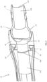
- FIG. 6 shown is a cross-sectional view of the swivel to body connection and swivel to hose connection are shown in detail.
- the body 22 may be formed with a projection 90 that fits into a slot 92 formed in the swivel portion 70. The engagement of the projection 90 with the slot 92 allows for rotation between the parts but maintains the coupling of the two parts.
- the hose connection 80 includes a projection 602 coupled to hose connection 80 that fits into a slot 604 formed in the swivel portion 70.
- Other mechanical means for joining the parts but allowing rotation of the swivel portion relative to the body will be evident to persons of ordinary skill in the art based on this disclosure.
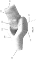
- a swivel portion 100 may be attached at an angle to a hose connector 105.
- the hose connector 105 is connected to the swivel portion 100 at an approximately forty-five degree angle.
- embodiments include the hose connector 105 being connected to the swivel portion 100 between approximately 0 degrees to 45 degrees.
- the angle allows the hose connection to be pointed straight back ( FIG. 7A ), collinear to the pen body 22, perpendicular to the pen body 22 ( FIG. 7B ), or any angle in between. While a forty-five degree angle is shown, the angle may increase or decrease to allow for a different range of movement.
- the hose connector 105 may rotate in the direction of arrows 110 and 120.
- a second pivot point 800 may be located between the body and the swivel portion.
- the swivel portion is connected to the body as disclosed in FIG. 3 discussed above and may rotate about the longitudinal axis of the body as illustrated by arrows 802, 804.
- FIG. 9 shown is a cross-sectional view of the embodiment shown in FIG. 8 depicting the swivel 100 to body 22 connection and the swivel 100 to hose 105 connection.
- the swivel 100 to body 22 connection is similar to the connection shown and described in FIG. 3 with a projection 904 extending into a corresponding slot 902 allowing for rotation of swivel 100 relative to body 22.
- Illustrated in FIG. 9 is the swivel 100 to hose 105 connection at a forty five degree angle.
- the connection between swivel 100 and hose 105 uses a projection 908 and a corresponding slot 906 that provides for rotation but does not allow the parts to separate.
- each of the swivel 100 to body 22 connection and the swivel 100 to hose 105 connection may be set at alternative angles.
- the swivel 100 to body 22 connection may be at a twenty degree angle while the swivel 100 to hose 105 connection may be at a ninety degree angle.
- a barbed fitting 28 is disposed on the outlet 104 of the hose 105 connection.
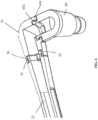
- another embodiment of the invention includes a swivel portion 200 having a pair of arms 210 and 215 that extend parallel to each other.
- a hose connection 220 is pivotally attached to the swivel portion 200 by means of a pivot pin 222 extending between the arms 210, 215.
- the hose connection 220 has an opening for receiving the pivot pin 222.
- the swivel portion 200 and the arms 210 and 215 are all hollow such that air from the passageway 302 passes through the body 22 and into the swivel portion 200. From the swivel portion 200, the air flows into the hose 220 connector through a hollow pivot pin 222. The air then exits through the center of the hose connector 220.
Landscapes
- Health & Medical Sciences (AREA)
- Surgery (AREA)
- Engineering & Computer Science (AREA)
- Life Sciences & Earth Sciences (AREA)
- Biomedical Technology (AREA)
- Otolaryngology (AREA)
- Nuclear Medicine, Radiotherapy & Molecular Imaging (AREA)
- Plasma & Fusion (AREA)
- Physics & Mathematics (AREA)
- Heart & Thoracic Surgery (AREA)
- Medical Informatics (AREA)
- Molecular Biology (AREA)
- Animal Behavior & Ethology (AREA)
- General Health & Medical Sciences (AREA)
- Public Health (AREA)
- Veterinary Medicine (AREA)
- Surgical Instruments (AREA)
Claims (6)
- Elektrochirurgische Vorrichtung (20), wobei die elektrochirurgische Vorrichtung (20) umfasst:einen Körper (22) mit einer Längsachse (45), wobei der Körper einen hohlen Durchgang (302) aufweist, der sich durch die Längsachse (45) von einem Einlass (1102) an einem distalen Ende (1104) zu einer Öffnung (306) an einem proximalen Ende (39) erstreckt;eine Elektrode (1100), die sich vom distalen Ende (1104) des Körpers (22) angrenzend an den Einlass (1102) erstreckt; undeinen Schwenkabschnitt (42, 64; 70, 80; 100, 105), der beweglich mit der Öffnung (306) gekoppelt ist, wobei der Schwenkabschnitt (42, 64; 70, 80; 100, 105) einen zweiten hohlen Durchgang (304) aufweist, der in Fluidverbindung mit dem hohlen Durchgang (302) steht, wobei sich der zweite hohle Durchgang (304) von der Öffnung (306) zu einem Auslass (104) erstreckt;wobei der Schwenkabschnitt (42, 64; 70, 80; 100, 105) ein erstes Schwenkelement (42; 70; 100) und ein zweites Schwenkelement (64; 80; 105) umfasst;wobei das erste Schwenkelement (42; 70; 100) so betrieben werden kann, dass es sich um die Längsachse (45) relativ zum Körper (22) dreht; undwobei das zweite Schwenkelement (64; 80; 105) so betätigt werden kann, dass es sich relativ zum ersten Schwenkelement (42; 70; 100) und dem Körper (22) dreht; undwobei das erste Schwenkelement (42; 70; 100) mit dem zweiten Schwenkelement (64; 80; 105) in einem Winkel zwischen 0 Grad und 45 Grad relativ zur Längsachse (45) verbunden ist;dadurch gekennzeichnet, dass das zweite Schwenkelement (64; 80; 105) so betätigt werden kann, dass es sich um eine Achse dreht, die in einem Winkel zwischen 45 Grad und 90 Grad relativ zur Längsachse (45) ausgerichtet ist.
- Elektrochirurgische Vorrichtung (20) nach Anspruch 1, wobei der Auslass (104) abnehmbar an ein Vakuumrohr (202) und ein Vakuum (204) angeschlossen werden kann; und
wobei der Körper (22) mit dem hohlen Durchgang (302) und der Schwenkabschnitt (42, 64; 70, 80; 100, 105) mit dem zweiten hohlen Durchgang (304) mit dem Vakuum (204) und dem Vakuumrohr (202) betreibbar sind, um chirurgischen Rauch aus einem durchströmten Hohlraum zu evakuieren. - Elektrochirurgische Vorrichtung (20) nach Anspruch 1, wobei die elektrochirurgische Vorrichtung (20) ferner einen ersten Knopf (33) und einen zweiten Knopf (36) an dem Körper (22) umfasst, die relativ zum Einlass (1102) beabstandet sind, wobei der erste und der zweite Knopf (33, 36) betätigt werden können, um einen Stromfluss zu der Elektrode (1100) zu steuern.
- Verfahren zur Bereitstellung einer elektrochirurgischen Vorrichtung (20) nach einem der Ansprüche 1 bis 3, wobei das Verfahren durch die folgenden Schritte gekennzeichnet ist:(a) Bereitstellen eines Körpers (22) mit einer Längsachse (45), wobei der Körper (22) einen hohlen Durchgang (302) aufweist, der sich durch die Längsachse (45) von einem Einlass (1102) an einem distalen Ende (1104) zu einer Öffnung (306) an einem proximalen Ende (39) erstreckt;(b) Bereitstellen einer Elektrode (1100), die sich von dem distalen Ende (1104) des Körpers (22) angrenzend an den Einlass (1102) erstreckt; und(c) Bereitstellen eines Schwenkabschnitts (100, 105), der beweglich mit der Öffnung (306) gekoppelt ist, wobei der Schwenkabschnitt (100, 105) einen zweiten hohlen Durchgang (304) aufweist, der in Fluidverbindung mit dem hohlen Durchgang (302) steht, wobei sich der zweite hohle Durchgang (304) von der Öffnung (306) zu einem Auslass (104) erstreckt;wobei der Schwenkabschnitt (100, 105) ein erstes Schwenkelement (100) und ein zweites Schwenkelement (105) umfasst;wobei das erste Schwenkelement (100) so betrieben werden kann, dass es sich um die Längsachse (45) relativ zum Körper (22) dreht;wobei das erste Schwenkelement (100) mit dem zweiten Schwenkelement (105) in einem Winkel zwischen 0 Grad und 45 Grad relativ zur Längsachse (45) verbunden ist;wobei das zweite Schwenkelement (105) relativ zu dem ersten Schwenkelement (100) und dem Körper (22) drehbar ist; unddadurch gekennzeichnet, dass das zweite Schwenkelement (105) so betätigt werden kann, dass es sich um eine Achse dreht, die in einem Winkel zwischen 45 Grad und 90 Grad relativ zur Längsachse (45) ausgerichtet ist.
- Verfahren nach Anspruch 4, wobei der Auslass (104) abnehmbar an ein Vakuumrohr (202) und ein Vakuum (204) angeschlossen werden kann.
- Verfahren nach Anspruch 4, wobei das elektrochirurgische Gerät (20) ferner einen ersten Knopf (33) und einen zweiten Knopf (36) an dem Körper (22) umfasst, die relativ zum Einlass (1102) beabstandet sind, wobei der erste und der zweite Knopf (33, 36) betätigt werden können, um einen Stromfluss zu der Elektrode (1100) zu steuern.
Applications Claiming Priority (2)
| Application Number | Priority Date | Filing Date | Title |
|---|---|---|---|
| US201662369625P | 2016-08-01 | 2016-08-01 | |
| PCT/US2017/044927 WO2018026832A1 (en) | 2016-08-01 | 2017-08-01 | Electrosurgical device with vacuum port having multiple swivel connections |
Publications (3)
| Publication Number | Publication Date |
|---|---|
| EP3490477A1 EP3490477A1 (de) | 2019-06-05 |
| EP3490477A4 EP3490477A4 (de) | 2020-05-06 |
| EP3490477B1 true EP3490477B1 (de) | 2025-04-23 |
Family
ID=61011789
Family Applications (1)
| Application Number | Title | Priority Date | Filing Date |
|---|---|---|---|
| EP17837551.5A Active EP3490477B1 (de) | 2016-08-01 | 2017-08-01 | Elektrochirurgische vorrichtung mit vakuumport mit mehreren schwenkverbindungen |
Country Status (5)
| Country | Link |
|---|---|
| US (2) | US11849993B2 (de) |
| EP (1) | EP3490477B1 (de) |
| AU (1) | AU2017305300B2 (de) |
| CA (2) | CA3032419C (de) |
| WO (1) | WO2018026832A1 (de) |
Families Citing this family (6)
| Publication number | Priority date | Publication date | Assignee | Title |
|---|---|---|---|---|
| US11617611B2 (en) * | 2016-06-17 | 2023-04-04 | Megadayne Medical Products, Inc. | Hand-held instrument with dual zone fluid removal |
| US20180333195A1 (en) * | 2017-05-18 | 2018-11-22 | Megadyne Medical Products, Inc. | Hand-held instrument with body-swivel |
| US11266384B2 (en) * | 2018-04-20 | 2022-03-08 | Johnson & Johnson Surgical Vision, Inc. | Ergonomic handpiece |
| US11547463B2 (en) * | 2018-09-21 | 2023-01-10 | Covidien Lp | Smoke evacuation electrosurgical pencil with adjustable electrode and vent tube |
| US11712281B2 (en) * | 2018-10-26 | 2023-08-01 | Buffalo Filter Llc | Filtering system, apparatus, and method |
| GB2621613B (en) * | 2022-08-16 | 2025-04-23 | Gyrus Medical Ltd | Surgical device |
Family Cites Families (12)
| Publication number | Priority date | Publication date | Assignee | Title |
|---|---|---|---|---|
| US4911159A (en) * | 1988-11-21 | 1990-03-27 | Johnson Jeffrey W | Electrosurgical instrument with electrical contacts between the probe and the probe holder |
| US5674219A (en) * | 1994-10-06 | 1997-10-07 | Donaldson Company, Inc. | Electrosurgical smoke evacuator |
| US6063081A (en) | 1995-02-22 | 2000-05-16 | Medtronic, Inc. | Fluid-assisted electrocautery device |
| CA2299752A1 (en) * | 2000-02-28 | 2001-08-28 | Cst Coldswitch Technologies Inc. | Electro-surgical pencil with smoke evacuation |
| US7241294B2 (en) | 2003-11-19 | 2007-07-10 | Sherwood Services Ag | Pistol grip electrosurgical pencil with manual aspirator/irrigator and methods of using the same |
| US9101386B2 (en) | 2004-10-15 | 2015-08-11 | Amendia, Inc. | Devices and methods for treating tissue |
| US8414576B2 (en) * | 2005-12-02 | 2013-04-09 | Ioan Cosmescu | Swivel device for electrosurgery pencil and surgical smoke evacuation |
| US9289261B2 (en) * | 2010-02-04 | 2016-03-22 | Buffalo Filter Llc | Electrosurgical device with vacuum port |
| US9636167B2 (en) | 2011-05-31 | 2017-05-02 | Covidien Lp | Surgical device with DC power connection |
| AU2012388657B2 (en) | 2012-08-28 | 2017-09-07 | Covidien Lp | Adjustable electrosurgical pencil |
| US10420603B2 (en) | 2014-12-23 | 2019-09-24 | Applied Medical Resources Corporation | Bipolar electrosurgical sealer and divider |
| CN114225125A (zh) * | 2015-07-13 | 2022-03-25 | 康曼德公司 | 使用正压气体的手术抽吸装置 |
-
2017
- 2017-08-01 EP EP17837551.5A patent/EP3490477B1/de active Active
- 2017-08-01 AU AU2017305300A patent/AU2017305300B2/en active Active
- 2017-08-01 US US15/665,859 patent/US11849993B2/en active Active
- 2017-08-01 CA CA3032419A patent/CA3032419C/en active Active
- 2017-08-01 CA CA3079331A patent/CA3079331C/en active Active
- 2017-08-01 WO PCT/US2017/044927 patent/WO2018026832A1/en not_active Ceased
-
2023
- 2023-12-01 US US18/526,635 patent/US20240099762A1/en active Pending
Also Published As
| Publication number | Publication date |
|---|---|
| CA3079331C (en) | 2022-11-15 |
| US20180028255A1 (en) | 2018-02-01 |
| CA3032419C (en) | 2021-11-30 |
| AU2017305300B2 (en) | 2020-05-21 |
| WO2018026832A1 (en) | 2018-02-08 |
| CA3079331A1 (en) | 2018-02-08 |
| AU2017305300A1 (en) | 2019-02-07 |
| EP3490477A4 (de) | 2020-05-06 |
| CA3032419A1 (en) | 2018-02-08 |
| US11849993B2 (en) | 2023-12-26 |
| EP3490477A1 (de) | 2019-06-05 |
| US20240099762A1 (en) | 2024-03-28 |
Similar Documents
| Publication | Publication Date | Title |
|---|---|---|
| US20240099762A1 (en) | Electrosurgical device with vacuum port having multiple swivel connections | |
| US12576433B2 (en) | Method and apparatus for attachment and evacuation | |
| EP2285303B1 (de) | Elektrochirurgischer Stift mit einer Schwenkvorrichtung | |
| AU2017249242B2 (en) | Electrosurgical device with vacuum port | |
| US20230082376A1 (en) | Directed gas flow accessory for providing gases to and venting gases from a patient | |
| ES2794835T3 (es) | Dispositivo electroquirúrgico con puerto de vacío | |
| US11607484B2 (en) | Variable suction control | |
| US12446952B2 (en) | Smoke evacuation pencil | |
| AU2019384814B2 (en) | Method and apparatus for flow | |
| CA3093039C (en) | Method and apparatus for fluid evacuation during surgical procedures |
Legal Events
| Date | Code | Title | Description |
|---|---|---|---|
| STAA | Information on the status of an ep patent application or granted ep patent |
Free format text: STATUS: THE INTERNATIONAL PUBLICATION HAS BEEN MADE |
|
| PUAI | Public reference made under article 153(3) epc to a published international application that has entered the european phase |
Free format text: ORIGINAL CODE: 0009012 |
|
| STAA | Information on the status of an ep patent application or granted ep patent |
Free format text: STATUS: REQUEST FOR EXAMINATION WAS MADE |
|
| 17P | Request for examination filed |
Effective date: 20190122 |
|
| AK | Designated contracting states |
Kind code of ref document: A1 Designated state(s): AL AT BE BG CH CY CZ DE DK EE ES FI FR GB GR HR HU IE IS IT LI LT LU LV MC MK MT NL NO PL PT RO RS SE SI SK SM TR |
|
| AX | Request for extension of the european patent |
Extension state: BA ME |
|
| DAV | Request for validation of the european patent (deleted) | ||
| DAX | Request for extension of the european patent (deleted) | ||
| RIC1 | Information provided on ipc code assigned before grant |
Ipc: A61B 18/14 20060101ALI20191220BHEP Ipc: A61B 18/20 20060101ALI20191220BHEP Ipc: A61B 18/00 20060101AFI20191220BHEP |
|
| A4 | Supplementary search report drawn up and despatched |
Effective date: 20200407 |
|
| RIC1 | Information provided on ipc code assigned before grant |
Ipc: A61B 18/20 20060101ALI20200401BHEP Ipc: A61B 18/14 20060101ALI20200401BHEP Ipc: A61B 18/00 20060101AFI20200401BHEP |
|
| STAA | Information on the status of an ep patent application or granted ep patent |
Free format text: STATUS: EXAMINATION IS IN PROGRESS |
|
| 17Q | First examination report despatched |
Effective date: 20220511 |
|
| P01 | Opt-out of the competence of the unified patent court (upc) registered |
Effective date: 20230529 |
|
| REG | Reference to a national code |
Ipc: A61B0018140000 Ref country code: DE Ref legal event code: R079 Ref document number: 602017089080 Country of ref document: DE Free format text: PREVIOUS MAIN CLASS: A61B0018000000 Ipc: A61B0018140000 |
|
| GRAP | Despatch of communication of intention to grant a patent |
Free format text: ORIGINAL CODE: EPIDOSNIGR1 |
|
| STAA | Information on the status of an ep patent application or granted ep patent |
Free format text: STATUS: GRANT OF PATENT IS INTENDED |
|
| RIC1 | Information provided on ipc code assigned before grant |
Ipc: A61B 18/14 20060101AFI20241119BHEP |
|
| INTG | Intention to grant announced |
Effective date: 20241128 |
|
| GRAJ | Information related to disapproval of communication of intention to grant by the applicant or resumption of examination proceedings by the epo deleted |
Free format text: ORIGINAL CODE: EPIDOSDIGR1 |
|
| STAA | Information on the status of an ep patent application or granted ep patent |
Free format text: STATUS: EXAMINATION IS IN PROGRESS |
|
| GRAP | Despatch of communication of intention to grant a patent |
Free format text: ORIGINAL CODE: EPIDOSNIGR1 |
|
| STAA | Information on the status of an ep patent application or granted ep patent |
Free format text: STATUS: GRANT OF PATENT IS INTENDED |
|
| GRAS | Grant fee paid |
Free format text: ORIGINAL CODE: EPIDOSNIGR3 |
|
| GRAA | (expected) grant |
Free format text: ORIGINAL CODE: 0009210 |
|
| STAA | Information on the status of an ep patent application or granted ep patent |
Free format text: STATUS: THE PATENT HAS BEEN GRANTED |
|
| INTC | Intention to grant announced (deleted) | ||
| INTG | Intention to grant announced |
Effective date: 20250318 |
|
| AK | Designated contracting states |
Kind code of ref document: B1 Designated state(s): AL AT BE BG CH CY CZ DE DK EE ES FI FR GB GR HR HU IE IS IT LI LT LU LV MC MK MT NL NO PL PT RO RS SE SI SK SM TR |
|
| REG | Reference to a national code |
Ref country code: GB Ref legal event code: FG4D |
|
| REG | Reference to a national code |
Ref country code: CH Ref legal event code: EP |
|
| REG | Reference to a national code |
Ref country code: DE Ref legal event code: R096 Ref document number: 602017089080 Country of ref document: DE |
|
| REG | Reference to a national code |
Ref country code: IE Ref legal event code: FG4D |
|
| REG | Reference to a national code |
Ref country code: NL Ref legal event code: MP Effective date: 20250423 |
|
| PG25 | Lapsed in a contracting state [announced via postgrant information from national office to epo] |
Ref country code: NL Free format text: LAPSE BECAUSE OF FAILURE TO SUBMIT A TRANSLATION OF THE DESCRIPTION OR TO PAY THE FEE WITHIN THE PRESCRIBED TIME-LIMIT Effective date: 20250423 |
|
| REG | Reference to a national code |
Ref country code: AT Ref legal event code: MK05 Ref document number: 1787039 Country of ref document: AT Kind code of ref document: T Effective date: 20250423 |
|
| PG25 | Lapsed in a contracting state [announced via postgrant information from national office to epo] |
Ref country code: PT Free format text: LAPSE BECAUSE OF FAILURE TO SUBMIT A TRANSLATION OF THE DESCRIPTION OR TO PAY THE FEE WITHIN THE PRESCRIBED TIME-LIMIT Effective date: 20250825 Ref country code: ES Free format text: LAPSE BECAUSE OF FAILURE TO SUBMIT A TRANSLATION OF THE DESCRIPTION OR TO PAY THE FEE WITHIN THE PRESCRIBED TIME-LIMIT Effective date: 20250423 Ref country code: FI Free format text: LAPSE BECAUSE OF FAILURE TO SUBMIT A TRANSLATION OF THE DESCRIPTION OR TO PAY THE FEE WITHIN THE PRESCRIBED TIME-LIMIT Effective date: 20250423 |
|
| PGFP | Annual fee paid to national office [announced via postgrant information from national office to epo] |
Ref country code: DE Payment date: 20250722 Year of fee payment: 9 |
|
| REG | Reference to a national code |
Ref country code: LT Ref legal event code: MG9D |
|
| PG25 | Lapsed in a contracting state [announced via postgrant information from national office to epo] |
Ref country code: GR Free format text: LAPSE BECAUSE OF FAILURE TO SUBMIT A TRANSLATION OF THE DESCRIPTION OR TO PAY THE FEE WITHIN THE PRESCRIBED TIME-LIMIT Effective date: 20250724 Ref country code: NO Free format text: LAPSE BECAUSE OF FAILURE TO SUBMIT A TRANSLATION OF THE DESCRIPTION OR TO PAY THE FEE WITHIN THE PRESCRIBED TIME-LIMIT Effective date: 20250723 |
|
| PG25 | Lapsed in a contracting state [announced via postgrant information from national office to epo] |
Ref country code: PL Free format text: LAPSE BECAUSE OF FAILURE TO SUBMIT A TRANSLATION OF THE DESCRIPTION OR TO PAY THE FEE WITHIN THE PRESCRIBED TIME-LIMIT Effective date: 20250423 |
|
| PGFP | Annual fee paid to national office [announced via postgrant information from national office to epo] |
Ref country code: IT Payment date: 20250728 Year of fee payment: 9 |
|
| PG25 | Lapsed in a contracting state [announced via postgrant information from national office to epo] |
Ref country code: BG Free format text: LAPSE BECAUSE OF FAILURE TO SUBMIT A TRANSLATION OF THE DESCRIPTION OR TO PAY THE FEE WITHIN THE PRESCRIBED TIME-LIMIT Effective date: 20250423 |
|
| PGFP | Annual fee paid to national office [announced via postgrant information from national office to epo] |
Ref country code: GB Payment date: 20250724 Year of fee payment: 9 |
|
| PG25 | Lapsed in a contracting state [announced via postgrant information from national office to epo] |
Ref country code: HR Free format text: LAPSE BECAUSE OF FAILURE TO SUBMIT A TRANSLATION OF THE DESCRIPTION OR TO PAY THE FEE WITHIN THE PRESCRIBED TIME-LIMIT Effective date: 20250423 |
|
| PG25 | Lapsed in a contracting state [announced via postgrant information from national office to epo] |
Ref country code: AT Free format text: LAPSE BECAUSE OF FAILURE TO SUBMIT A TRANSLATION OF THE DESCRIPTION OR TO PAY THE FEE WITHIN THE PRESCRIBED TIME-LIMIT Effective date: 20250423 |
|
| PGFP | Annual fee paid to national office [announced via postgrant information from national office to epo] |
Ref country code: FR Payment date: 20250808 Year of fee payment: 9 |
|
| PG25 | Lapsed in a contracting state [announced via postgrant information from national office to epo] |
Ref country code: RS Free format text: LAPSE BECAUSE OF FAILURE TO SUBMIT A TRANSLATION OF THE DESCRIPTION OR TO PAY THE FEE WITHIN THE PRESCRIBED TIME-LIMIT Effective date: 20250723 |
|
| PG25 | Lapsed in a contracting state [announced via postgrant information from national office to epo] |
Ref country code: IS Free format text: LAPSE BECAUSE OF FAILURE TO SUBMIT A TRANSLATION OF THE DESCRIPTION OR TO PAY THE FEE WITHIN THE PRESCRIBED TIME-LIMIT Effective date: 20250823 |
|
| PG25 | Lapsed in a contracting state [announced via postgrant information from national office to epo] |
Ref country code: LV Free format text: LAPSE BECAUSE OF FAILURE TO SUBMIT A TRANSLATION OF THE DESCRIPTION OR TO PAY THE FEE WITHIN THE PRESCRIBED TIME-LIMIT Effective date: 20250423 |
|
| PG25 | Lapsed in a contracting state [announced via postgrant information from national office to epo] |
Ref country code: SM Free format text: LAPSE BECAUSE OF FAILURE TO SUBMIT A TRANSLATION OF THE DESCRIPTION OR TO PAY THE FEE WITHIN THE PRESCRIBED TIME-LIMIT Effective date: 20250423 Ref country code: DK Free format text: LAPSE BECAUSE OF FAILURE TO SUBMIT A TRANSLATION OF THE DESCRIPTION OR TO PAY THE FEE WITHIN THE PRESCRIBED TIME-LIMIT Effective date: 20250423 |
|
| PG25 | Lapsed in a contracting state [announced via postgrant information from national office to epo] |
Ref country code: CZ Free format text: LAPSE BECAUSE OF FAILURE TO SUBMIT A TRANSLATION OF THE DESCRIPTION OR TO PAY THE FEE WITHIN THE PRESCRIBED TIME-LIMIT Effective date: 20250423 |
|
| PG25 | Lapsed in a contracting state [announced via postgrant information from national office to epo] |
Ref country code: EE Free format text: LAPSE BECAUSE OF FAILURE TO SUBMIT A TRANSLATION OF THE DESCRIPTION OR TO PAY THE FEE WITHIN THE PRESCRIBED TIME-LIMIT Effective date: 20250423 |
|
| REG | Reference to a national code |
Ref country code: DE Ref legal event code: R097 Ref document number: 602017089080 Country of ref document: DE |
|
| PG25 | Lapsed in a contracting state [announced via postgrant information from national office to epo] |
Ref country code: SK Free format text: LAPSE BECAUSE OF FAILURE TO SUBMIT A TRANSLATION OF THE DESCRIPTION OR TO PAY THE FEE WITHIN THE PRESCRIBED TIME-LIMIT Effective date: 20250423 Ref country code: RO Free format text: LAPSE BECAUSE OF FAILURE TO SUBMIT A TRANSLATION OF THE DESCRIPTION OR TO PAY THE FEE WITHIN THE PRESCRIBED TIME-LIMIT Effective date: 20250423 |
|
| PLBE | No opposition filed within time limit |
Free format text: ORIGINAL CODE: 0009261 |
|
| STAA | Information on the status of an ep patent application or granted ep patent |
Free format text: STATUS: NO OPPOSITION FILED WITHIN TIME LIMIT |
|
| REG | Reference to a national code |
Ref country code: CH Ref legal event code: L10 Free format text: ST27 STATUS EVENT CODE: U-0-0-L10-L00 (AS PROVIDED BY THE NATIONAL OFFICE) Effective date: 20260304 |
|
| REG | Reference to a national code |
Ref country code: CH Ref legal event code: H13 Free format text: ST27 STATUS EVENT CODE: U-0-0-H10-H13 (AS PROVIDED BY THE NATIONAL OFFICE) Effective date: 20260324 |
|
| PG25 | Lapsed in a contracting state [announced via postgrant information from national office to epo] |
Ref country code: MC Free format text: LAPSE BECAUSE OF FAILURE TO SUBMIT A TRANSLATION OF THE DESCRIPTION OR TO PAY THE FEE WITHIN THE PRESCRIBED TIME-LIMIT Effective date: 20250423 |
|
| 26N | No opposition filed |
Effective date: 20260126 |
|
| PG25 | Lapsed in a contracting state [announced via postgrant information from national office to epo] |
Ref country code: LU Free format text: LAPSE BECAUSE OF NON-PAYMENT OF DUE FEES Effective date: 20250801 |
|
| PG25 | Lapsed in a contracting state [announced via postgrant information from national office to epo] |
Ref country code: CH Free format text: LAPSE BECAUSE OF NON-PAYMENT OF DUE FEES Effective date: 20250831 |