EP3490391B1 - Aerosolerzeugungssystem mit einem beheizten gelbehälter - Google Patents
Aerosolerzeugungssystem mit einem beheizten gelbehälter Download PDFInfo
- Publication number
- EP3490391B1 EP3490391B1 EP17737555.7A EP17737555A EP3490391B1 EP 3490391 B1 EP3490391 B1 EP 3490391B1 EP 17737555 A EP17737555 A EP 17737555A EP 3490391 B1 EP3490391 B1 EP 3490391B1
- Authority
- EP
- European Patent Office
- Prior art keywords
- aerosol
- gel
- generating system
- heater
- cartridge
- Prior art date
- Legal status (The legal status is an assumption and is not a legal conclusion. Google has not performed a legal analysis and makes no representation as to the accuracy of the status listed.)
- Active
Links
- 239000000758 substrate Substances 0.000 claims description 56
- 239000000443 aerosol Substances 0.000 claims description 27
- SNICXCGAKADSCV-JTQLQIEISA-N (-)-Nicotine Chemical compound CN1CCC[C@H]1C1=CC=CN=C1 SNICXCGAKADSCV-JTQLQIEISA-N 0.000 claims description 18
- 229960002715 nicotine Drugs 0.000 claims description 18
- SNICXCGAKADSCV-UHFFFAOYSA-N nicotine Natural products CN1CCCC1C1=CC=CN=C1 SNICXCGAKADSCV-UHFFFAOYSA-N 0.000 claims description 18
- 239000007788 liquid Substances 0.000 claims description 17
- 239000007787 solid Substances 0.000 claims description 10
- 238000007789 sealing Methods 0.000 claims description 7
- 238000002844 melting Methods 0.000 claims description 6
- 230000008018 melting Effects 0.000 claims description 6
- 235000019505 tobacco product Nutrition 0.000 claims description 2
- 239000000499 gel Substances 0.000 description 77
- 238000010438 heat treatment Methods 0.000 description 46
- 239000000463 material Substances 0.000 description 34
- PEDCQBHIVMGVHV-UHFFFAOYSA-N Glycerine Chemical compound OCC(O)CO PEDCQBHIVMGVHV-UHFFFAOYSA-N 0.000 description 29
- 239000003570 air Substances 0.000 description 25
- 241000208125 Nicotiana Species 0.000 description 14
- 235000002637 Nicotiana tabacum Nutrition 0.000 description 14
- 235000011187 glycerol Nutrition 0.000 description 12
- 229920001817 Agar Polymers 0.000 description 11
- 239000008272 agar Substances 0.000 description 11
- 229910052751 metal Inorganic materials 0.000 description 11
- 239000002184 metal Substances 0.000 description 11
- 150000001875 compounds Chemical class 0.000 description 10
- 230000006698 induction Effects 0.000 description 10
- -1 polyethylene terephthalate Polymers 0.000 description 10
- 239000000203 mixture Substances 0.000 description 9
- XLYOFNOQVPJJNP-UHFFFAOYSA-N water Substances O XLYOFNOQVPJJNP-UHFFFAOYSA-N 0.000 description 9
- 230000004888 barrier function Effects 0.000 description 8
- 238000005485 electric heating Methods 0.000 description 8
- 239000000796 flavoring agent Substances 0.000 description 8
- 239000000919 ceramic Substances 0.000 description 7
- 239000011888 foil Substances 0.000 description 7
- 239000002775 capsule Substances 0.000 description 6
- PXHVJJICTQNCMI-UHFFFAOYSA-N Nickel Chemical compound [Ni] PXHVJJICTQNCMI-UHFFFAOYSA-N 0.000 description 5
- 239000004411 aluminium Substances 0.000 description 5
- 229910052782 aluminium Inorganic materials 0.000 description 5
- XAGFODPZIPBFFR-UHFFFAOYSA-N aluminium Chemical compound [Al] XAGFODPZIPBFFR-UHFFFAOYSA-N 0.000 description 5
- 235000019634 flavors Nutrition 0.000 description 5
- 239000012528 membrane Substances 0.000 description 5
- 230000004044 response Effects 0.000 description 5
- PUPZLCDOIYMWBV-UHFFFAOYSA-N (+/-)-1,3-Butanediol Chemical compound CC(O)CCO PUPZLCDOIYMWBV-UHFFFAOYSA-N 0.000 description 4
- XEEYBQQBJWHFJM-UHFFFAOYSA-N Iron Chemical compound [Fe] XEEYBQQBJWHFJM-UHFFFAOYSA-N 0.000 description 4
- 239000004696 Poly ether ether ketone Substances 0.000 description 4
- 230000004913 activation Effects 0.000 description 4
- 229910045601 alloy Inorganic materials 0.000 description 4
- 239000000956 alloy Substances 0.000 description 4
- 239000011324 bead Substances 0.000 description 4
- 239000004020 conductor Substances 0.000 description 4
- 230000005672 electromagnetic field Effects 0.000 description 4
- 238000001879 gelation Methods 0.000 description 4
- 239000003349 gelling agent Substances 0.000 description 4
- 238000011065 in-situ storage Methods 0.000 description 4
- 230000005291 magnetic effect Effects 0.000 description 4
- 150000002739 metals Chemical class 0.000 description 4
- 229920002530 polyetherether ketone Polymers 0.000 description 4
- 238000003860 storage Methods 0.000 description 4
- 230000032258 transport Effects 0.000 description 4
- 229920002148 Gellan gum Polymers 0.000 description 3
- 239000004642 Polyimide Substances 0.000 description 3
- DNIAPMSPPWPWGF-UHFFFAOYSA-N Propylene glycol Chemical compound CC(O)CO DNIAPMSPPWPWGF-UHFFFAOYSA-N 0.000 description 3
- 239000011248 coating agent Substances 0.000 description 3
- 238000000576 coating method Methods 0.000 description 3
- 239000002131 composite material Substances 0.000 description 3
- 239000000216 gellan gum Substances 0.000 description 3
- 235000010492 gellan gum Nutrition 0.000 description 3
- 239000012669 liquid formulation Substances 0.000 description 3
- 238000000034 method Methods 0.000 description 3
- 229920003223 poly(pyromellitimide-1,4-diphenyl ether) Polymers 0.000 description 3
- 229920001721 polyimide Polymers 0.000 description 3
- 239000010935 stainless steel Substances 0.000 description 3
- 229910001220 stainless steel Inorganic materials 0.000 description 3
- 150000005846 sugar alcohols Polymers 0.000 description 3
- 229920000936 Agarose Polymers 0.000 description 2
- OKTJSMMVPCPJKN-UHFFFAOYSA-N Carbon Chemical compound [C] OKTJSMMVPCPJKN-UHFFFAOYSA-N 0.000 description 2
- VYZAMTAEIAYCRO-UHFFFAOYSA-N Chromium Chemical compound [Cr] VYZAMTAEIAYCRO-UHFFFAOYSA-N 0.000 description 2
- 239000004812 Fluorinated ethylene propylene Substances 0.000 description 2
- 239000004698 Polyethylene Substances 0.000 description 2
- 239000002202 Polyethylene glycol Substances 0.000 description 2
- 239000004743 Polypropylene Substances 0.000 description 2
- 229910052581 Si3N4 Inorganic materials 0.000 description 2
- PNEYBMLMFCGWSK-UHFFFAOYSA-N aluminium oxide Inorganic materials [O-2].[O-2].[O-2].[Al+3].[Al+3] PNEYBMLMFCGWSK-UHFFFAOYSA-N 0.000 description 2
- 230000015572 biosynthetic process Effects 0.000 description 2
- GUTLYIVDDKVIGB-UHFFFAOYSA-N cobalt atom Chemical compound [Co] GUTLYIVDDKVIGB-UHFFFAOYSA-N 0.000 description 2
- 238000010276 construction Methods 0.000 description 2
- ZDJFDFNNEAPGOP-UHFFFAOYSA-N dimethyl tetradecanedioate Chemical compound COC(=O)CCCCCCCCCCCCC(=O)OC ZDJFDFNNEAPGOP-UHFFFAOYSA-N 0.000 description 2
- 238000001914 filtration Methods 0.000 description 2
- 239000011810 insulating material Substances 0.000 description 2
- 229910052742 iron Inorganic materials 0.000 description 2
- 229910001092 metal group alloy Inorganic materials 0.000 description 2
- 239000007769 metal material Substances 0.000 description 2
- 229910052759 nickel Inorganic materials 0.000 description 2
- 229920009441 perflouroethylene propylene Polymers 0.000 description 2
- 229920000573 polyethylene Polymers 0.000 description 2
- 229920001223 polyethylene glycol Polymers 0.000 description 2
- 229920000139 polyethylene terephthalate Polymers 0.000 description 2
- 239000005020 polyethylene terephthalate Substances 0.000 description 2
- 229920000642 polymer Polymers 0.000 description 2
- 229920001155 polypropylene Polymers 0.000 description 2
- 229920001343 polytetrafluoroethylene Polymers 0.000 description 2
- 239000004810 polytetrafluoroethylene Substances 0.000 description 2
- HQVNEWCFYHHQES-UHFFFAOYSA-N silicon nitride Chemical compound N12[Si]34N5[Si]62N3[Si]51N64 HQVNEWCFYHHQES-UHFFFAOYSA-N 0.000 description 2
- GUVRBAGPIYLISA-UHFFFAOYSA-N tantalum atom Chemical compound [Ta] GUVRBAGPIYLISA-UHFFFAOYSA-N 0.000 description 2
- 239000002470 thermal conductor Substances 0.000 description 2
- 239000010936 titanium Substances 0.000 description 2
- 229910052719 titanium Inorganic materials 0.000 description 2
- 230000007723 transport mechanism Effects 0.000 description 2
- ZIBGPFATKBEMQZ-UHFFFAOYSA-N triethylene glycol Chemical compound OCCOCCOCCO ZIBGPFATKBEMQZ-UHFFFAOYSA-N 0.000 description 2
- NOOLISFMXDJSKH-UTLUCORTSA-N (+)-Neomenthol Chemical compound CC(C)[C@@H]1CC[C@@H](C)C[C@@H]1O NOOLISFMXDJSKH-UTLUCORTSA-N 0.000 description 1
- IXPNQXFRVYWDDI-UHFFFAOYSA-N 1-methyl-2,4-dioxo-1,3-diazinane-5-carboximidamide Chemical compound CN1CC(C(N)=N)C(=O)NC1=O IXPNQXFRVYWDDI-UHFFFAOYSA-N 0.000 description 1
- 229910001369 Brass Inorganic materials 0.000 description 1
- 229910001006 Constantan Inorganic materials 0.000 description 1
- RYGMFSIKBFXOCR-UHFFFAOYSA-N Copper Chemical compound [Cu] RYGMFSIKBFXOCR-UHFFFAOYSA-N 0.000 description 1
- NOOLISFMXDJSKH-UHFFFAOYSA-N DL-menthol Natural products CC(C)C1CCC(C)CC1O NOOLISFMXDJSKH-UHFFFAOYSA-N 0.000 description 1
- 229910000640 Fe alloy Inorganic materials 0.000 description 1
- WHXSMMKQMYFTQS-UHFFFAOYSA-N Lithium Chemical compound [Li] WHXSMMKQMYFTQS-UHFFFAOYSA-N 0.000 description 1
- HBBGRARXTFLTSG-UHFFFAOYSA-N Lithium ion Chemical compound [Li+] HBBGRARXTFLTSG-UHFFFAOYSA-N 0.000 description 1
- ZOKXTWBITQBERF-UHFFFAOYSA-N Molybdenum Chemical compound [Mo] ZOKXTWBITQBERF-UHFFFAOYSA-N 0.000 description 1
- 239000004793 Polystyrene Substances 0.000 description 1
- BQCADISMDOOEFD-UHFFFAOYSA-N Silver Chemical compound [Ag] BQCADISMDOOEFD-UHFFFAOYSA-N 0.000 description 1
- 229910000831 Steel Inorganic materials 0.000 description 1
- ATJFFYVFTNAWJD-UHFFFAOYSA-N Tin Chemical compound [Sn] ATJFFYVFTNAWJD-UHFFFAOYSA-N 0.000 description 1
- RTAQQCXQSZGOHL-UHFFFAOYSA-N Titanium Chemical compound [Ti] RTAQQCXQSZGOHL-UHFFFAOYSA-N 0.000 description 1
- 102100029469 WD repeat and HMG-box DNA-binding protein 1 Human genes 0.000 description 1
- 101710097421 WD repeat and HMG-box DNA-binding protein 1 Proteins 0.000 description 1
- QCWXUUIWCKQGHC-UHFFFAOYSA-N Zirconium Chemical compound [Zr] QCWXUUIWCKQGHC-UHFFFAOYSA-N 0.000 description 1
- 239000002253 acid Substances 0.000 description 1
- 150000007513 acids Chemical class 0.000 description 1
- 230000003213 activating effect Effects 0.000 description 1
- 238000012387 aerosolization Methods 0.000 description 1
- 125000001931 aliphatic group Chemical group 0.000 description 1
- KCZFLPPCFOHPNI-UHFFFAOYSA-N alumane;iron Chemical compound [AlH3].[Fe] KCZFLPPCFOHPNI-UHFFFAOYSA-N 0.000 description 1
- 239000012080 ambient air Substances 0.000 description 1
- 239000012298 atmosphere Substances 0.000 description 1
- 230000009286 beneficial effect Effects 0.000 description 1
- YXTPWUNVHCYOSP-UHFFFAOYSA-N bis($l^{2}-silanylidene)molybdenum Chemical compound [Si]=[Mo]=[Si] YXTPWUNVHCYOSP-UHFFFAOYSA-N 0.000 description 1
- 238000000071 blow moulding Methods 0.000 description 1
- 239000010951 brass Substances 0.000 description 1
- OJIJEKBXJYRIBZ-UHFFFAOYSA-N cadmium nickel Chemical compound [Ni].[Cd] OJIJEKBXJYRIBZ-UHFFFAOYSA-N 0.000 description 1
- 239000003990 capacitor Substances 0.000 description 1
- 229910052799 carbon Inorganic materials 0.000 description 1
- 230000015556 catabolic process Effects 0.000 description 1
- 229910010293 ceramic material Inorganic materials 0.000 description 1
- 229910052804 chromium Inorganic materials 0.000 description 1
- 239000011651 chromium Substances 0.000 description 1
- 235000019504 cigarettes Nutrition 0.000 description 1
- 229910017052 cobalt Inorganic materials 0.000 description 1
- 239000010941 cobalt Substances 0.000 description 1
- CKFRRHLHAJZIIN-UHFFFAOYSA-N cobalt lithium Chemical compound [Li].[Co] CKFRRHLHAJZIIN-UHFFFAOYSA-N 0.000 description 1
- 238000001816 cooling Methods 0.000 description 1
- 229910052802 copper Inorganic materials 0.000 description 1
- 239000010949 copper Substances 0.000 description 1
- 229910052593 corundum Inorganic materials 0.000 description 1
- 238000006731 degradation reaction Methods 0.000 description 1
- IZMOTZDBVPMOFE-UHFFFAOYSA-N dimethyl dodecanedioate Chemical compound COC(=O)CCCCCCCCCCC(=O)OC IZMOTZDBVPMOFE-UHFFFAOYSA-N 0.000 description 1
- 239000013013 elastic material Substances 0.000 description 1
- 238000005265 energy consumption Methods 0.000 description 1
- 239000003822 epoxy resin Substances 0.000 description 1
- 150000002148 esters Chemical class 0.000 description 1
- HQQADJVZYDDRJT-UHFFFAOYSA-N ethene;prop-1-ene Chemical group C=C.CC=C HQQADJVZYDDRJT-UHFFFAOYSA-N 0.000 description 1
- 238000001125 extrusion Methods 0.000 description 1
- 239000003302 ferromagnetic material Substances 0.000 description 1
- 239000012530 fluid Substances 0.000 description 1
- 239000012634 fragment Substances 0.000 description 1
- 239000011521 glass Substances 0.000 description 1
- PCHJSUWPFVWCPO-UHFFFAOYSA-N gold Chemical compound [Au] PCHJSUWPFVWCPO-UHFFFAOYSA-N 0.000 description 1
- 229910052737 gold Inorganic materials 0.000 description 1
- 239000010931 gold Substances 0.000 description 1
- 239000008187 granular material Substances 0.000 description 1
- 239000010439 graphite Substances 0.000 description 1
- 229910002804 graphite Inorganic materials 0.000 description 1
- VBJZVLUMGGDVMO-UHFFFAOYSA-N hafnium atom Chemical compound [Hf] VBJZVLUMGGDVMO-UHFFFAOYSA-N 0.000 description 1
- LNEPOXFFQSENCJ-UHFFFAOYSA-N haloperidol Chemical compound C1CC(O)(C=2C=CC(Cl)=CC=2)CCN1CCCC(=O)C1=CC=C(F)C=C1 LNEPOXFFQSENCJ-UHFFFAOYSA-N 0.000 description 1
- 238000001746 injection moulding Methods 0.000 description 1
- DALUDRGQOYMVLD-UHFFFAOYSA-N iron manganese Chemical compound [Mn].[Fe] DALUDRGQOYMVLD-UHFFFAOYSA-N 0.000 description 1
- 229910052744 lithium Inorganic materials 0.000 description 1
- 229910001416 lithium ion Inorganic materials 0.000 description 1
- GELKBWJHTRAYNV-UHFFFAOYSA-K lithium iron phosphate Chemical compound [Li+].[Fe+2].[O-]P([O-])([O-])=O GELKBWJHTRAYNV-UHFFFAOYSA-K 0.000 description 1
- 210000004072 lung Anatomy 0.000 description 1
- 238000012423 maintenance Methods 0.000 description 1
- 230000014759 maintenance of location Effects 0.000 description 1
- 229940041616 menthol Drugs 0.000 description 1
- 229910052987 metal hydride Inorganic materials 0.000 description 1
- 239000010445 mica Substances 0.000 description 1
- 229910052618 mica group Inorganic materials 0.000 description 1
- 238000002156 mixing Methods 0.000 description 1
- 239000003607 modifier Substances 0.000 description 1
- 229910021343 molybdenum disilicide Inorganic materials 0.000 description 1
- 229910000623 nickel–chromium alloy Inorganic materials 0.000 description 1
- GUCVJGMIXFAOAE-UHFFFAOYSA-N niobium atom Chemical compound [Nb] GUCVJGMIXFAOAE-UHFFFAOYSA-N 0.000 description 1
- 230000037361 pathway Effects 0.000 description 1
- 239000008188 pellet Substances 0.000 description 1
- 230000000149 penetrating effect Effects 0.000 description 1
- BASFCYQUMIYNBI-UHFFFAOYSA-N platinum Chemical group [Pt] BASFCYQUMIYNBI-UHFFFAOYSA-N 0.000 description 1
- 229920000647 polyepoxide Polymers 0.000 description 1
- 229920005749 polyurethane resin Polymers 0.000 description 1
- 239000000843 powder Substances 0.000 description 1
- 229920005989 resin Polymers 0.000 description 1
- 239000011347 resin Substances 0.000 description 1
- 239000004065 semiconductor Substances 0.000 description 1
- 229910010271 silicon carbide Inorganic materials 0.000 description 1
- 229920002379 silicone rubber Polymers 0.000 description 1
- 229910052709 silver Inorganic materials 0.000 description 1
- 239000004332 silver Substances 0.000 description 1
- 239000000661 sodium alginate Substances 0.000 description 1
- 235000010413 sodium alginate Nutrition 0.000 description 1
- 229940005550 sodium alginate Drugs 0.000 description 1
- 125000006850 spacer group Chemical group 0.000 description 1
- 239000010959 steel Substances 0.000 description 1
- 229910000601 superalloy Inorganic materials 0.000 description 1
- 229910052715 tantalum Inorganic materials 0.000 description 1
- 231100000331 toxic Toxicity 0.000 description 1
- 230000002588 toxic effect Effects 0.000 description 1
- 230000007704 transition Effects 0.000 description 1
- ILJSQTXMGCGYMG-UHFFFAOYSA-N triacetic acid Chemical compound CC(=O)CC(=O)CC(O)=O ILJSQTXMGCGYMG-UHFFFAOYSA-N 0.000 description 1
- WFKWXMTUELFFGS-UHFFFAOYSA-N tungsten Chemical compound [W] WFKWXMTUELFFGS-UHFFFAOYSA-N 0.000 description 1
- 125000000391 vinyl group Chemical group [H]C([*])=C([H])[H] 0.000 description 1
- 229920002554 vinyl polymer Polymers 0.000 description 1
- 229910001845 yogo sapphire Inorganic materials 0.000 description 1
- 229910052726 zirconium Inorganic materials 0.000 description 1
Images


Classifications
-
- A—HUMAN NECESSITIES
- A24—TOBACCO; CIGARS; CIGARETTES; SIMULATED SMOKING DEVICES; SMOKERS' REQUISITES
- A24F—SMOKERS' REQUISITES; MATCH BOXES; SIMULATED SMOKING DEVICES
- A24F47/00—Smokers' requisites not otherwise provided for
-
- A—HUMAN NECESSITIES
- A24—TOBACCO; CIGARS; CIGARETTES; SIMULATED SMOKING DEVICES; SMOKERS' REQUISITES
- A24F—SMOKERS' REQUISITES; MATCH BOXES; SIMULATED SMOKING DEVICES
- A24F40/00—Electrically operated smoking devices; Component parts thereof; Manufacture thereof; Maintenance or testing thereof; Charging means specially adapted therefor
- A24F40/40—Constructional details, e.g. connection of cartridges and battery parts
- A24F40/46—Shape or structure of electric heating means
-
- A—HUMAN NECESSITIES
- A24—TOBACCO; CIGARS; CIGARETTES; SIMULATED SMOKING DEVICES; SMOKERS' REQUISITES
- A24F—SMOKERS' REQUISITES; MATCH BOXES; SIMULATED SMOKING DEVICES
- A24F40/00—Electrically operated smoking devices; Component parts thereof; Manufacture thereof; Maintenance or testing thereof; Charging means specially adapted therefor
- A24F40/40—Constructional details, e.g. connection of cartridges and battery parts
- A24F40/42—Cartridges or containers for inhalable precursors
-
- A—HUMAN NECESSITIES
- A61—MEDICAL OR VETERINARY SCIENCE; HYGIENE
- A61M—DEVICES FOR INTRODUCING MEDIA INTO, OR ONTO, THE BODY; DEVICES FOR TRANSDUCING BODY MEDIA OR FOR TAKING MEDIA FROM THE BODY; DEVICES FOR PRODUCING OR ENDING SLEEP OR STUPOR
- A61M11/00—Sprayers or atomisers specially adapted for therapeutic purposes
- A61M11/04—Sprayers or atomisers specially adapted for therapeutic purposes operated by the vapour pressure of the liquid to be sprayed or atomised
- A61M11/041—Sprayers or atomisers specially adapted for therapeutic purposes operated by the vapour pressure of the liquid to be sprayed or atomised using heaters
- A61M11/042—Sprayers or atomisers specially adapted for therapeutic purposes operated by the vapour pressure of the liquid to be sprayed or atomised using heaters electrical
-
- A—HUMAN NECESSITIES
- A61—MEDICAL OR VETERINARY SCIENCE; HYGIENE
- A61M—DEVICES FOR INTRODUCING MEDIA INTO, OR ONTO, THE BODY; DEVICES FOR TRANSDUCING BODY MEDIA OR FOR TAKING MEDIA FROM THE BODY; DEVICES FOR PRODUCING OR ENDING SLEEP OR STUPOR
- A61M15/00—Inhalators
- A61M15/0028—Inhalators using prepacked dosages, one for each application, e.g. capsules to be perforated or broken-up
- A61M15/003—Inhalators using prepacked dosages, one for each application, e.g. capsules to be perforated or broken-up using capsules, e.g. to be perforated or broken-up
- A61M15/0033—Details of the piercing or cutting means
- A61M15/0035—Piercing means
- A61M15/0036—Piercing means hollow piercing means
-
- A—HUMAN NECESSITIES
- A61—MEDICAL OR VETERINARY SCIENCE; HYGIENE
- A61M—DEVICES FOR INTRODUCING MEDIA INTO, OR ONTO, THE BODY; DEVICES FOR TRANSDUCING BODY MEDIA OR FOR TAKING MEDIA FROM THE BODY; DEVICES FOR PRODUCING OR ENDING SLEEP OR STUPOR
- A61M15/00—Inhalators
- A61M15/06—Inhaling appliances shaped like cigars, cigarettes or pipes
-
- A—HUMAN NECESSITIES
- A24—TOBACCO; CIGARS; CIGARETTES; SIMULATED SMOKING DEVICES; SMOKERS' REQUISITES
- A24F—SMOKERS' REQUISITES; MATCH BOXES; SIMULATED SMOKING DEVICES
- A24F40/00—Electrically operated smoking devices; Component parts thereof; Manufacture thereof; Maintenance or testing thereof; Charging means specially adapted therefor
- A24F40/20—Devices using solid inhalable precursors
-
- A—HUMAN NECESSITIES
- A61—MEDICAL OR VETERINARY SCIENCE; HYGIENE
- A61M—DEVICES FOR INTRODUCING MEDIA INTO, OR ONTO, THE BODY; DEVICES FOR TRANSDUCING BODY MEDIA OR FOR TAKING MEDIA FROM THE BODY; DEVICES FOR PRODUCING OR ENDING SLEEP OR STUPOR
- A61M16/00—Devices for influencing the respiratory system of patients by gas treatment, e.g. mouth-to-mouth respiration; Tracheal tubes
- A61M16/0003—Accessories therefor, e.g. sensors, vibrators, negative pressure
- A61M2016/0015—Accessories therefor, e.g. sensors, vibrators, negative pressure inhalation detectors
- A61M2016/0018—Accessories therefor, e.g. sensors, vibrators, negative pressure inhalation detectors electrical
- A61M2016/0024—Accessories therefor, e.g. sensors, vibrators, negative pressure inhalation detectors electrical with an on-off output signal, e.g. from a switch
-
- A—HUMAN NECESSITIES
- A61—MEDICAL OR VETERINARY SCIENCE; HYGIENE
- A61M—DEVICES FOR INTRODUCING MEDIA INTO, OR ONTO, THE BODY; DEVICES FOR TRANSDUCING BODY MEDIA OR FOR TAKING MEDIA FROM THE BODY; DEVICES FOR PRODUCING OR ENDING SLEEP OR STUPOR
- A61M2205/00—General characteristics of the apparatus
- A61M2205/33—Controlling, regulating or measuring
- A61M2205/3368—Temperature
-
- A—HUMAN NECESSITIES
- A61—MEDICAL OR VETERINARY SCIENCE; HYGIENE
- A61M—DEVICES FOR INTRODUCING MEDIA INTO, OR ONTO, THE BODY; DEVICES FOR TRANSDUCING BODY MEDIA OR FOR TAKING MEDIA FROM THE BODY; DEVICES FOR PRODUCING OR ENDING SLEEP OR STUPOR
- A61M2205/00—General characteristics of the apparatus
- A61M2205/82—Internal energy supply devices
- A61M2205/8206—Internal energy supply devices battery-operated
Definitions
- the present invention relates to an aerosol-generating system that heats an aerosol-forming substrate to generate an aerosol.
- the invention relates to an aerosol generating system that heats a gel to form an aerosol.
- Aerosol-generating systems such as e-cigarettes, that operate by heating a liquid formulation to generate an aerosol for inhalation by users are widely used.
- WO 2013/128176 discloses an aerosol delivery device comprising a plurality of vapour-generating units, each unit comprising a dose of a composition to be vaporised and a heat source; a housing defining an airway; and a mouthpiece.
- WO 2016/005601 A1 discloses an electrically operated aerosol-generating system comprising an aerosol-generating device, a removable aerosol-forming cartridge and a removable heater.
- the aerosol-forming cartridge comprises at least one aerosol-forming substrate, and the heater comprises at least one electric heater element and first electrical contacts connected to the at least one electric heater element.
- the aerosol-generating device comprises a main body defining a main cavity and at least one opening for receiving the aerosol-forming cartridge and the heater within the main cavity.
- the aerosol-generating device also comprises an electric power supply.
- WO 2015/101479 A1 discloses a capsule for an aerosol-generating device, comprising: a shell comprising a base and at least one side wall extending from the base, the shell containing an aerosol-forming substrate; and a lid sealed on the at least one side wall for forming a sealed capsule, wherein, the base comprises a recess extending into said shell along the longitudinal axis for receiving a heater of an aerosol-generating device. Also disclosed is an aerosol-generating device for such a cartridge.
- WO 2016/096927 A1 discloses a sachet of aerosol-forming substrate for use in an electrically heated aerosol-generating device.
- the sachet comprises: a porous container; and an aerosol-forming substrate.
- EP 3 794 999 A1 discloses an apparatus for heating smokable material to volatilise at least one component of the smokable material, the apparatus comprising: an interface for cooperating with an article comprising smokable material, a magnetic field generator for generating a varying magnetic field for penetrating the article when the interface is cooperating with the article, and a device for puncturing the article. Also disclosed is a cartridge for use with such apparatus.
- the device portion typically contains a power supply and control electronics and the cartridge contains a liquid reservoir holding the liquid formulation, a heater for vapourising the liquid formulation, and a wick that transports the liquid from the liquid reservoir to the heater. While this type of system has become popular, it does have disadvantages.
- One disadvantage is the potential for leakage of the liquid from the liquid reservoir both during transport and storage, and when the cartridge is connected to the device portion.
- the use of a wick to transport the liquid from the reservoir to the heater may add complexity to the system.
- an aerosol-generating system comprising:
- an aerosol-forming substrate is a material or mixture of materials capable of releasing volatile compounds that can form an aerosol.
- the provision of the aerosol-forming substrate in the form of a gel may be advantageous for storage and transport, or during use.
- the risk of leakage from the device may be reduced.
- Replenishing of the device with aerosol forming substrate when depleted or exhausted may also be improved, for example by reducing the risk of leakage or spillage.
- “Blind” in this context means closed at one end. Preferably, there is only one aperture for entry to and exit from the cavity.
- the heating of the gel without requiring the gel to contact the heater is advantageous because it reduces the possibility of unwanted material building up on the heater. If the heater is separate to the gel, the heater can remain clean and so less maintenance may be required and the performance of the system may be more reliable and consistent.
- the substrate container may contain other materials in addition to the gel.
- the gel is solid at room temperature.
- Solid in this context means that the gel has a stable size and shape and does not flow.
- Room temperature in this context means 25 degrees Celsius.
- the gel comprises an aerosol-former.
- aerosol-former refers to any suitable known compound or mixture of compounds that, in use, facilitates formation of a dense and stable aerosol.
- An aerosol-former is substantially resistant to thermal degradation at the operating temperature of the cartridge.
- Suitable aerosol-formers are well known in the art and include, but are not limited to: polyhydric alcohols, such as triethylene glycol, 1,3-butanediol and glycerine; esters of polyhydric alcohols, such as glycerol mono-, di- or triacetate; and aliphatic esters of mono-, di- or polycarboxylic acids, such as dimethyl dodecanedioate and dimethyl tetradecanedioate.
- Preferred aerosol formers are polyhydric alcohols or mixtures thereof, such as triethylene glycol, 1,3-butanediol and, most preferred, glycerine or polyethylene glycol.
- the gel comprises a thermoreversible gel. This means that the gel will become fluid when heated to a melting temperature and will set into a gel again at a gelation temperature.
- the gelation temperature is preferably at or above room temperature and atmospheric pressure. Atmospheric pressure means a pressure of 1 atmosphere.
- the melting temperature is preferably higher than the gelation temperature. Preferably the melting temperature of the gel is above 50 degrees Celsius, or 60 degrees Celsius or 70 degrees Celsius and more preferably above 80 degrees Celsius. The melting temperature in this context means the temperature at which the gel is no longer solid and begins to flow.
- the gel may comprise a gelling agent.
- the gel comprises agar or agarose or sodium alginate.
- the gel may comprise Gellan gum.
- the gel may comprise a mixture of materials.
- the gel may comprise water.
- the gel may be provided as a single block or may be provided as a plurality of gel elements, for example beads or capsules.
- the use of beads or capsules may allow for simple refilling of the first (or second) chamber by the end user.
- the use of capsules or beads may also allow a user to see when a cartridge has already been used because gel will not form the same capsules or beads on gelation after heating and subsequent cooling.
- the gel may comprise nicotine or a tobacco product or another target compound for delivery to a user.
- the resulting aerosol is to contain nicotine, it is advantageous for the nicotine to be contained in the gel or in another solid form in the substrate container rather than in a liquid.
- the nicotine can be included in the gel with an aerosol-former. Nicotine is irritating to the skin and can be toxic. Preventing any possible leakage of nicotine by locking the nicotine into a gel at room temperature is therefore desirable.
- Flavour compounds may be contained in the second chamber in a gel.
- flavour compound may be provided in another form.
- the second chamber may contain a solid tobacco material that releases flavour compounds when heated.
- the second chamber may contain, for example, one or more of: powder, granules, pellets, shreds, spaghettis, strips or sheets containing one or more of: herb leaf, tobacco leaf, fragments of tobacco ribs, reconstituted tobacco, homogenised tobacco, extruded tobacco and expanded tobacco.
- the solid tobacco material in the second chamber may be in loose form.
- the tobacco may be contained in a gel or liquid.
- the second chamber may contain additional tobacco or non-tobacco volatile flavour compounds, to be released upon heating.
- the gel When agar is used as the gelling agent, the gel preferably comprises between 0.5 and 5% by weight (and more preferably between 0.8 and1% by weight) agar.
- the gel may further comprise between 0.1 and 2% by weight nicotine.
- the gel may further comprise between 30% and 90% by weight (and more preferably between 70 and 90% by weight) glycerin.
- a remainder of the gel may comprise water and any flavourings.
- the gel preferably comprises between 0.5 and 5% by weight Gellan gum.
- the gel may further comprise between 0.1 and 2% by weight nicotine.
- the gel may further comprise between 30% and 99.4% by weight gylcerin.
- a remainder of the gel may comprise water and any flavourings.
- the gel comprises 2% by weight nicotine, 70% by weight glycerol, 27% by weight water and 1% by weight agar. In another embodiment, the gel comprises 65% by weight glycerol, 20% by weight water, 14.3% by weight tobacco and 0.7% by weight agar
- the system does not comprise a transport mechanism for transporting the gel to the electrical heater.
- the contents of the substrate container are advantageously heated in situ to generate a desired aerosol.
- in situ means in the same position within substrate container that the contents are held prior to use. There is no requirement for a capillary wick or pump.
- the system does not comprise an additional non-volatile structure within the substrate container for holding or retaining a liquid or gel in proximity to the heater.
- the system comprises a device and a separate consumable portion wherein the consumable portion is configured to connect to or be received in the device, and wherein the device comprises the electrical power supply and the consumable portion comprises the substrate container.
- the consumable portion may be conveniently referred to as a cartridge.
- the cartridge can be easily disposed of and replaced when the gel has been consumed.
- the device advantageously comprises at least a portion of the electrical heater. By providing the heater in the device, the cartridge can be made simple and inexpensive.
- the electrical heater may be configured to heat the cartridge to generate a vapour within the cartridge from the gel.
- the device comprises a device housing having a cavity for receiving the cartridge.
- the cavity of the device may be substantially cylindrical.
- the cavity has a diameter substantially equal to or slightly greater than the diameter of the cartridge.
- the aerosol-generating device may comprise a device body and may further comprise a mouthpiece separate to the device body.
- the mouthpiece may be configured for engagement with the device body.
- the device body is configured to receive the consumable portion in a cavity of the device body.
- At least one wall of the substrate container is in thermal contact with the heater.
- the at least one wall of the substrate container may be positioned between the heater and the aerosol-forming substrate.
- the at least one wall of the substrate container may advantageously be in direct contact with the heater.
- the gel within the substrate container can then be heated by conduction through the external wall.
- the substrate container comprises at least one liquid impermeable and vapour impermeable external wall defining a blind cavity.
- the cartridge may have any suitable shape.
- the cartridge is substantially cylindrical.
- cylinder and “cylindrical” refer to a substantially right circular cylinder with a pair of opposed substantially planar end faces.
- the cartridge may have any suitable size.
- the cartridge may have a length of, for example, between about 5 mm and about 30 mm. In certain embodiments the cartridge may have a length of about 12 mm.
- the cartridge may have a diameter of, for example, between about 4 mm and about 10 mm. In certain embodiments the cartridge may have a diameter of about 7 mm.
- the substrate container or cartridge may comprise a housing.
- the housing of the cartridge may be formed from one or more materials. Suitable materials include, but are not limited to, metal, aluminium, polymer, polyether ether ketone (PEEK), polyimides, such as Kapton ® , polyethylene terephthalate (PET), polyethylene (PE), polypropylene (PP), polystyrene (PS), fluorinated ethylene propylene (FEP), polytetrafluoroethylene (PTFE), epoxy resins, polyurethane resins and vinyl resins.
- PEEK polyether ether ketone
- polyimides such as Kapton ® , polyethylene terephthalate (PET), polyethylene (PE), polypropylene (PP), polystyrene (PS), fluorinated ethylene propylene (FEP), polytetrafluoroethylene (PTFE), epoxy resins, polyurethane resins and vinyl resins.
- the housing of the cartridge may be formed from one or more thermally conductive materials.
- the interior of the cartridge may be coated or treated to comprise one or more thermally conductive materials.
- Use of one or more thermally conductive materials to form the cartridge or coat the interior of the cartridge can advantageously increase heat transfer from the heater to the gel.
- Suitable thermally conductive materials include, but are not limited to, metals such as, for example, aluminium, chromium, copper, gold, iron, nickel and silver, alloys, such as brass and steel and ceramics, or combinations thereof.
- at least one wall of the housing has a thermal conductivity greater than 10 Watts per metre per Kelvin at room temperature.
- the housing comprises a least one wall formed from aluminium.
- the housing of the cartridge may comprise a susceptor, for example a susceptor layer.
- the susceptor layer may for example form a wall of the housing or may be a coating applied to the interior or exterior of the housing.
- a susceptor may be located within a chamber in the cartridge.
- the gel may comprise a susceptor material.
- Cartridges for use in aerosol-generating systems according to the present invention may be formed by any suitable method. Suitable methods include, but are not limited to, deep drawing, injection moulding, blistering, blow forming and extrusion.
- the cartridge may comprise a mouthpiece configured to allow a user to puff on the mouthpiece to draw aerosol into their mouth or lungs.
- the mouthpiece may comprise a filter.
- the filter may have a low particulate filtration efficiency or very low particulate filtration efficiency.
- the mouthpiece may comprise a hollow tube.
- the mouthpiece may comprise an airflow modifier, for example a restrictor.
- the cartridge may be provided within a mouthpiece tube.
- the mouthpiece tube may comprise an aerosol-forming chamber.
- the mouthpiece tube may comprise an airflow restrictor.
- the mouthpiece tube may comprise a filter.
- the mouthpiece tube may comprise a cardboard housing.
- the mouthpiece tube may comprise one or more vapour impermeable elements within the cardboard tube.
- the mouthpiece tube may have a diameter similar to a conventional cigarette, for example around 7mm.
- the mouthpiece tube may have a mouth end configured to be placed in a user's mouth for inhalation of aerosol therethrough.
- the cartridge may be held in the mouthpiece tube, for example at an opposite end to the mouth end.
- An open end of the substrate container may be sealed by one or more frangible barriers.
- the one or more frangible barriers may be formed from any suitable material.
- the one or more frangible barriers may be formed from a foil or film, for example comprising a metal.
- the device body preferably further comprises a piercing member configured to rupture the one or more frangible barriers.
- the substrate container may be sealed by one or more removable barriers.
- the substrate container may be sealed by one or more peel-off seals.
- the one or more removable barriers may be formed from any suitable material.
- the one or more removable barriers may be formed from a foil or film. for example comprising a metal.
- An open end of the substrate container may be sealed by a vapour permeable element, for example a membrane or mesh configured to allow the escape of vapour from the substrate container through the membrane or mesh.
- a vapour permeable element for example a membrane or mesh configured to allow the escape of vapour from the substrate container through the membrane or mesh.
- the substrate container may be sealed by a pressure activated valve that allows for the release of vapour through the valve when a pressure difference across the valve exceeds a threshold pressure difference.
- the substrate container may comprise a first chamber, containing the gel and a second chamber separate to the first chamber.
- the second chamber may contain the same gel as the first chamber or may contain a different gel or different material to the first chamber.
- the first and second chambers may be fixed together permanently or they may be separable from one another.
- the first and second chambers may be provided separately and fixed together by a user using a suitable mechanical interlock, such as a snap fitting or a screw fitting. Alternatively, the first and second chambers may remain separate during use.
- first and second chambers By providing the first and second chambers separately, a "mix and match" type set of choices may be made available to a user.
- the contents of the first chamber may provide a particular dosage of a target compound for delivery to a user, such as nicotine, and may provide a particular density of aerosol, and a range of options may be made available to the user.
- the contents of the second chamber may primarily provide flavour compounds, and a range of options for the second chamber may be available to the user.
- the user can choose one chamber from the range of first chambers and one chamber from the range of second chambers and may fit them together to form a complete cartridge.
- the first and second chambers may be of the same size and shape as one another or they may have a different size or shape to one another.
- the size and shape of the first and second chamber may be chosen to suit their contents, and to provide for a particular heating rate in use.
- the first and second chambers may advantageously contain different compositions. Both the first and second chambers may contain a gel.
- neither the first chamber nor the second chamber contains a liquid at room temperature.
- neither the first chamber nor the second chamber comprises a liquid retention material or a wicking material.
- the first and second chambers may be positioned side by side or one within the other or may be arranged in series such that an air flow can pass first through one chamber and then through the other.
- the cartridge may comprise a slot between the first and second chambers.
- the slot may be configured to receive a heating element.
- the heating element may be received in the slot for example when the cartridge is installed in an aerosol-forming device.
- the provision of a slot into which a heating element is received may provide for efficient heating by facilitating that heat energy from the heating element is passed directly to the interior of the substrate container rather than for example heating other elements of the system or the ambient air.
- the slot is a blind slot. Blind in this context means closed at one end. The provision of a blind slot allows the heating element to be shielded from the vapour or aerosol generated by the system and can help to prevent the build-up of condensates on the heater.
- the slot may be provided between the first the second chambers.
- the slot may be provided within a wall separating the first and second chambers.
- the electrical heater may comprise a resistive heater.
- the electrical heater may comprise one or more heating elements.
- the electric heating element may comprise one or more external heating elements, one or more internal heating elements, or one or more external heating elements and one or more internal heating elements.
- external means outside of the cavity and internal means inside of the cavity of the device.
- the one or more external heating elements may comprise an array of external heating elements arranged around the inner surface of the cavity.
- the external heating elements extend along the longitudinal direction of the cavity. With this arrangement, the heating elements may extend along the same direction in which the cartridge is inserted into and removed from the cavity. This may reduce interference between the heating elements and the cartridge.
- the external heating elements extend along the length direction of the cavity and are spaced apart in the circumferential direction.
- the heating element comprises one or more internal heating elements
- the one or more internal heating elements may comprise any suitable number of heating elements.
- the heating element may comprise a single internal heating element. The single internal heating element may extend along the longitudinal direction of the cavity.
- the electric heating element may comprise an electrically resistive material.
- Suitable electrically resistive materials include but are not limited to: semiconductors such as doped ceramics, electrically "conductive" ceramics (such as, for example, molybdenum disilicide), carbon, graphite, metals, metal alloys and composite materials made of a ceramic material and a metallic material.
- Such composite materials may comprise doped or undoped ceramics.
- suitable doped ceramics include doped silicon carbides.
- suitable metals include titanium, zirconium, tantalum and metals from the platinum group.
- suitable metal alloys include stainless steel, Constantan, nickel-, cobalt-, chromium-, aluminium- titanium- zirconium-, hafnium-, niobium-, molybdenum-, tantalum-, tungsten-, tin-, gallium-, manganese- and iron-containing alloys, and super-alloys based on nickel, iron, cobalt, stainless steel, Timetal ® , iron-aluminium based alloys and iron-manganese-aluminium based alloys. Timetal ® is a registered trade mark of Titanium Metals Corporation, 1999 Broadway Suite 4300, Denver Colorado.
- the electrically resistive material may optionally be embedded in, encapsulated or coated with an insulating material or vice-versa, depending on the kinetics of energy transfer and the external physicochemical properties required.
- the heating element may comprise a metallic etched foil insulated between two layers of an inert material.
- the inert material may comprise Kapton ® , all-polyimide or mica foil.
- Kapton ® is a registered trade mark of E.I. du Pont de Nemours and Company, 1007 Market Street, Wilmington, Delaware 19898, United States of America.
- a flexible heating element of this type may be conformed to the shape of the cavity and may extend around the periphery of the cavity.
- the electric heating element may be formed using a metal having a defined relationship between temperature and resistivity.
- the metal may be formed as a track between two layers of suitable insulating materials.
- An electric heating element formed in this manner may be used both as a heater and a temperature sensor.
- the aerosol-generating device body preferably comprises an inductor arranged to generate a fluctuating electromagnetic field within the cavity and an electrical power supply connected to the inductor.
- the inductor may comprise one or more coils that generate a fluctuating electromagnetic field.
- the coil or coils may surround the cavity.
- the device body is capable of generating a fluctuating electromagnetic field of between 1 and 30 MHz, for example, between 2 and 10 MHz, for example between 5 and 7 MHz.
- the device body is capable of generating a fluctuating electromagnetic field having a field strength (H-field) of between 1 and 5 kA/m, for example between 2 and 3 kA/m, for example about 2.5 kA/m.
- H-field field strength
- the aerosol-generating system according to the present invention may comprise a single heater.
- the single heater may be configured as an external heater that in use is positioned externally to the cavity.
- the single heater may be configured as an internal heater that in use is positioned internally to the cavity and received in a slot in the cartridge.
- the single heater is configured as an internal heater.
- the aerosol-generating device may advantageously comprise guide means to facilitate proper alignment of the internal heater with the cartridge.
- the single heater is an electric heating element comprising an electrically resistive material.
- the electric heating element may comprise a non-elastic material, for example a ceramic sintered material, such as glass, alumina (Al 2 O 3 ) and silicon nitride (Si 3 N 4 ), or printed circuit board or silicon rubber.
- the electric heating element may comprise an elastic, metallic material, for example an iron alloy or a nickel-chromium alloy.
- the single heater may have any shape suitable to heat the cartridge.
- the electrical heater may be positioned between first and second chambers of the cartridge when the cartridge is connected to or received in the device body. Preferably, the heater does not project from the aerosol-generating device.
- the electrical heater surrounds the substrate container.
- the electrical heater comprises one or more electrically resistive tracks on a flexible insulating substrate.
- the aerosol-generating system of the present invention may further comprise one or more temperature sensors configured to sense the temperature of at least one of the electrical heating elements.
- the system may comprise a controller and the controller may be configured to control a supply of power to the electrical heater based on the sensed temperature.
- the controller is configured to supply power to the heater continuously after activation of the system rather than in response to detected user puffs.
- the controller may be configured to supply power to the heater in response to user puffs.
- the system may comprise electronic circuitry to control the supply of power to the electric heater.
- the electronic circuitry may be a simple switch.
- the electronic circuitry may comprise one or more microprocessors or microcontrollers.
- the electronic circuitry may be programmable.
- the electrical power supply may be a DC voltage source.
- the power supply is a battery.
- the power supply may be a Nickel-metal hydride battery, a Nickel cadmium battery, or a Lithium based battery, for example a Lithium-Cobalt, a Lithium-Iron-Phosphate or a Lithium-Polymer battery.
- the power supply may alternatively be another form of charge storage device such as a capacitor.
- the power supply may require recharging and may have a capacity that allows for the storage of enough energy for use of the aerosol-generating device with one or more aerosol-generating articles.
- the aerosol-generating system is configured to generate an aerosol for inhalation by a user.
- the aerosol-generating system may be a handheld system and may comprise a mouthpiece on which a user sucks or draws in use.
- the system does not comprise a transport mechanism for transporting the aerosol-former to the heater.
- the contents of the cartridge are advantageously heated in situ to generate a desired aerosol.
- in situ means in the same position within the first and second chambers that the contents are held prior to use. There is no requirement for a capillary wick or pump.
- the aerosol-generating device is a portable or handheld aerosol-generating device that is comfortable for a user to hold between the fingers of a single hand.
- the aerosol-generating device may be substantially cylindrical in shape.
- the aerosol-generating device may have a length of between approximately 70 millimetres and approximately 120 millimetres.
- a cartridge for an aerosol-generating system comprising an electrical heater, the cartridge comprising: a substrate container comprising a blind cavity containing an aerosol-forming substrate in the form of a gel that is solid at room temperature, wherein the cartridge is configured to removably connect to or be received in a body of the aerosol-generating system.
- the substrate container may comprise at least one liquid and vapour impermeable external wall defining the blind cavity.
- the blind cavity may be sealed by a frangible, removable or vapour-permeable sealing element.
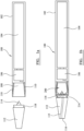
- FIG 1a is a schematic illustration of an aerosol-generating device in accordance with a first embodiment of the invention.
- Figure 1a shows a cross-sectional view of an aerosol-generating device 100 for use with a container 200 as shown in Figure 2 .
- the aerosol-generating device comprises an outer housing 102, containing a power supply 104 such as a rechargeable battery and control circuitry 106.
- the housing 102 further comprises a cavity 108 configured to receive a container 200.
- a heater 110 extends around the periphery of the cavity 108.
- the control circuitry is connected to the heater 110.
- the heater is formed from one or more metal heating tracks sandwiched between two layers of flexible, thermal stable substrate material, such as polyimide.
- the aerosol-generating device 100 further comprises a mouthpiece 112 attachable to a proximal end of the aerosol-generating device housing 102 by a push fitting or screw fitting.
- the mouthpiece comprises a piercing portion 114, air inlets 118 and an air outlet 116.
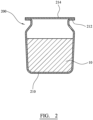
- a container or cartridge 200 that the user places in the cavity 108 of the device is shown in Figure 2 .
- the container has a housing 210 formed from aluminium, which is a good thermal conductor.
- the housing of the container is in the form of a cup, that defines a blind cavity.
- the housing 210 may be manufactured using suitable known techniques, such as deep drawing.
- the container contains a gel 10.
- the gel comprises 2% by weight nicotine, 70% by weight glycerol, 27% by weight water and 1% by weight agar.
- the gel comprises 65% by weight glycerol, 20% by weight water, 14.3% by weight solid powdered tobacco and 0.7% by weight agar.
- the gel is sealed in the cavity of the container by a frangible sealing foil 214.
- the sealing foil is welded, heat sealed or adhered to a lip 212 of the housing 210. This type of container can be made very inexpensively.
- Figure 1b shows a cross-sectional view of the aerosol-generating device 100 with a container 200 received in the cavity 108 of the housing.
- a user inserts the container 200 into the cavity 108 of the aerosol-generating device 100, and then attaches the mouthpiece 112 to the housing 102.
- the piercing portion 114 pierces the sealing foil 214 of the container, and forms an airflow pathway 115 from the air inlets 118, through the container to the air outlet.
- the user presses a button (not shown) to activate the device.
- the heater is supplied with power by the control electronics 106 from the power supply 104. The heater then directly heats the external wall of the cartridge.
- the user When the temperature of the container 200 reaches the operating temperature of about 250 degrees Celsius, the user is informed by means of an indicator (not shown) that the user may then draw on the mouthpiece at outlet 116.
- air enters the air inlets 118 When the user draws on the mouthpiece, air enters the air inlets 118, proceeds through the mouthpiece and into the container 200, entrains vapourised gel, and then exits to the user's mouth through the air outlet 116 in the mouthpiece.
- the heater may operate for a fixed time period after activation, say 6 minutes, or may operate until a user switches the system off.
- the cartridge When the gel in the cartridge has become exhausted, the cartridge can be removed by the user and replaced by a new cartridge.
- Figure 3 is a schematic illustration of an aerosol-generating system in accordance with a second embodiment of the invention.
- the embodiment of Figure 3 is operated by using induction heating rather than by using resistive heating.
- the device comprises an inductor coil 310 surrounding the cavity and a susceptor is provided in the cavity in this example as part of the cartridge.
- the aerosol-generating device comprises an outer housing 302, containing a power supply 304 such as a rechargeable battery and control circuitry 306.
- the housing 302 further comprises a cavity 308 configured to receive a container 250.
- An induction coil is positioned around the periphery of the cavity 308.
- the control circuitry is connected to the induction coil 310.
- the control circuitry includes components to generate an AC signal which is provided to the induction coil 224.
- the aerosol-generating device 100 further comprises a mouthpiece 312 attachable to a proximal end of the aerosol-generating device housing 302 by a push fitting or screw fitting.
- the mouthpiece comprises a piercing portion 314, and air inlets 318 and an air outlet 316 in the same manner as the embodiment of Figure 1 .
- the cartridge 250 of Figure 3 is similar to the cartridge shown in Figure 2 .
- the composition of the gel may be the same as in the embodiment of Figure 1 .
- the housing of the cartridge comprises a susceptor material that heats up in the alternating magnetic field.
- the susceptor may be provided as a coating on the inside or outside of the housing or may be within housing itself.
- the susceptor material in this example is stainless steel, which is provided as part of the cartridge rather than part of the device body, but it is possible for the susceptor material to be provided as part of the device body or both in the cartridge and the device body.
- the entire cartridge may be formed from a susceptor material, or a susceptor material may be provided as a coating or layer on one of more surfaces of the cartridge. It is also possible to provide susceptor material within the first and second chambers, suspended in the gel or other material contained there.
- the system is configured to operate in a continuous heating mode as in the embodiment of Figure 1 .
- the device supplies an AC signal to the induction coil in order to generate an alternating magnetic field in the cavity. This induces current flow in the susceptor resulting in a heating of the susceptor. If a ferromagnetic material is used as the susceptor, hysteresis losses may also contribute to the heating.
- the induction coil may be described as an induction heater in this context.
- a temperature sensor may be provided within the cavity 308 and a feedback control loop used. Again the induction heater may operate for a fixed time period after activation, say 6 minutes, or may operate until a user switches the system off.
- FIG. 4 is a schematic illustration of an aerosol-generating system in accordance with a third embodiment of the invention.
- the system comprises an aerosol-generating device 410 and a replaceable cartridge 420.
- the aerosol-generating device comprises a device body 412 and a mouthpiece portion 414.
- the device body 412 comprises a power supply, which is a lithium ion battery 416 and electronic control circuitry 418.
- the device body also includes heater 422, which is in the form a blade that projects into a cavity 424 in the housing of the device body.
- the heater is an electric heater comprising an electrically resistive track on a ceramic substrate material.
- the control circuitry is configured to control the supply of power from the battery 416 to the electric heater 422.
- the mouthpiece portion 414 engages the device body using a simple push fitting, although any type of connection, such as a snap fitting or screw fitting may be used.
- the mouthpiece portion in this embodiment is simply a tapered hollow tube, without any filter elements, and is shown in more detail in Figure 5 . However, it is possible to include one or more filter elements in the mouthpiece portion.
- the mouthpiece portion comprises air inlet holes 442 and encloses an aerosol-forming chamber 440 (shown in Figure 4 ) in which vapour can condense in an airflow prior to entering a user's mouth.
- the cartridge 420 comprises a housing defining a blind chamber.
- the chamber 430 is open at a mouthpiece end.
- a membrane 437 (shown in Figure 4 ) seals the open end of the chamber.
- a removable seal may be provided over the membrane that a user peels off before use.
- a blind slot 434 is provided that extends into the chamber for the heater 422 to be received in.
- the blind slot 434 is surrounded by a slot wall 439 and is closed at the mouthpiece end so that the heater does not contact the contents the contents of the chamber.
- the chamber 430 holds a gel, containing nicotine and aerosol-former, as described with reference to the embodiment of Figure 2 .
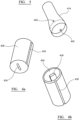
- Figure 6a is a bottom perspective view of the cartridge housing.
- Figure 6b is a perspective view of the cartridge housing.
- the cartridge 420 has a housing having a generally cylindrical shape.
- the slot wall 439 extends into the chamber.
- the blind slot 434 is within the slot wall.
- a channel 438 is provided in a wall of the cartridge housing to engage a corresponding rib in the cavity 424. This ensures that the cartridge can only be inserted into the cavity 424 in one orientation, in which the heater blade is received in the slot 434.
- the gel in the first chamber 430 comprises one or two aerosol formers such as glycerine, propylene glycol and polyethylene glycol.
- the relative concentration of the aerosol formers can be adapted to the particular requirements of the system.
- the gel in the first chamber 430 comprises (by weight): 2% nicotine, 70% glycerin, 27% water, 1 % agar.
- the gelling agent is preferably agar. It has the property of melting at temperatures above 85°C and turning back to gel at around 40°C. This property makes it suitable for hot environments. The gel will not melt at 50°C, which is useful if the system is left in a hot automobile in the sun, for example. A phase transition to liquid at around 85°C means that the gel only needs to be heated to a relatively low-temperature to induce aerosolization, allowing low energy consumption. It may be beneficial to use only agarose, which is one of the components of agar, instead of agar.
- the amount of gel provided in the cartridge can also be chosen to suit particular needs.
- the cartridge may contain enough gel to provide a single dose or usage session for a user or may contain sufficient gel for several or many doses or usage sessions.
- the system is configured to operate in a continuous heating mode.
- the heater 422 heats the cartridge throughout an operating session rather than in response to sensed user puffs.
- the user turns the system on using a simple switch (not shown) and the heater heats the cartridge.
- a temperature sensor may be included in the system so that a user can be provided with an indication of when an operating temperature has been reached, at which aerosol is generated.
- the gel becomes liquid upon heating above 85°C. Aerosol containing nicotine and glycerin is generated at temperatures between 180°C to 250°C.
- the heater operates at approximately 250°C.
- the heater may operate for a fixed time period after activation, say 6 minutes, or may operate until a user switches the system off. The operating time may depend on the amount of gel contained within the cartridge.
- the cartridge housing is formed of aluminium, which is a good thermal conductor.
- the heater is never in contact with the gel or any generated vapour or aerosol. It is held in the blind slot 434 and so is isolated from the generated aerosol. This ensures that there is no build-up of condensates on the heater, which might lead to the generation of undesirable compounds in operation.
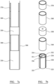
- FIGs 7a and b are schematic illustrations of a cartridge in accordance with a fourth embodiment of the invention.
- the cartridge 330 is held within a mouthpiece tube 300.
- a flow restrictor 350 and lining tubes 340, 360, 370 are also held within the mouthpiece tube.
- the components held within the mouthpiece tube 330 are shown in an exploded view in Figure 7b .
- the cartridge 330 is similar to the cartridge shown in Figures 6a and 6b .
- the cartridge 330 has a generally cylindrical shape.
- the cartridge 330 comprises a housing defining two blind chambers.
- the first and second chambers are of equal size and shape and are separated by a dividing wall 336.
- the two chambers 331, 332 are open at a mouthpiece end.
- a blind slot is provided in the dividing wall 336 between the two chambers for the heater to be received in.
- the blind slot is closed at the mouthpiece end.
- the first chamber 331 holds a first gel, containing nicotine and aerosol-former
- the second chamber 332 holds a second gel, containing shredded tobacco leaves.
- the cartridge 330 has no membrane or sealing element but includes airflow channels 335 formed in the walls of the cartridge and air inlets 334 at the top of the airflow channels to allow air into the open ends of the first and second chambers.
- the mouthpiece tube is formed from cardboard and has a diameter of 6.6mm and a length of 45 mm.
- Lining tubes 340 are formed from polyetheretherketone (PEEK) and are provided to prevent the cardboard mouthpiece tube from absorbing moisture from within the mouthpiece tube.
- the lining tubes can be made very thin, in this embodiment having a thickness of 0.3mm.
- a restrictor 350 is provided to restrict the airflow to ensure mixing of air with vapour from the cartridge and ensure the generation of an aerosol within the space following the restrictor, in lining tube 360.
- Figure 7 illustrates the airflow within the mouthpiece tube of Figure 6a during operation.
- the mouthpiece tube is shown within the cavity 24 of a device 12 of the type shown in Figure 1 .
- the device of Figure 7 does not have a mouthpiece.
- Figure 7 illustrates only the end of the device that receives the mouthpiece tube.
- the battery and control circuitry is not shown.
- the device includes device air inlets 355 that allow air into an internal air flow passage 365 formed in the device around the periphery of the cavity 24.
- a spacer element 352 is positioned in a base of the cavity to allow air to flow from the internal airflow passage 365 into the cavity 24 and then into the airflow channels 335 in the cartridge 330 and through the air inlets 334 into the interior of the mouthpiece tube.
- the cartridge shown in Figures 7a and 7b may be heated by heater of the type shown in Figure 4 or of the type shown in Figures 1 or 3 .
- the system is configured to operate in a continuous heating mode. This means that the heater heats the cartridge throughout an operating session rather than in response to sensed user puffs.
- the user turns the system on using a simple switch (not shown) and the heater heats the cartridge.
- the gels in the first and second chambers become liquid upon heating and vapour containing nicotine and glycerin is generated at temperatures between 180°C to 250°C.
- the user When the system is at the operating temperature, the user sucks on a mouth end of the mouthpiece tube to draw air through the mouthpiece tube. Air is drawn into a distal end of the mouthpiece tube, opposite the mouthpiece end from the internal passage 365. The air travels up the airflow channels 335 and through air inlets 334 into space 345. The air mixes in space 345 with vapour from the first and second chambers. The mixed air and vapour then passes through the restrictor 350, after which it cools to continue to form an aerosol before being drawn into a user's mouth. After operation, the mouthpiece tube, including the cartridge, can be withdrawn from the device and disposed of. Mouthpiece tubes of this type may be sold in packs to provide for multiple operations of the system.
- the embodiments described have each been described as configured to operate a continuous heating scheme, in which the heater is activated for a predetermined time period during which a user may take several puffs.
- the systems described may be configured to operate in different ways. For example, power may be provided to the heater or induction coil for only the duration of each user puff, based on signals from an airflow sensor within the system. Alternatively, or in addition, power to the heater or induction coil may be switched on and off in response to user actuation of a button or switch.
Claims (12)
- Aerosolerzeugungssystem, aufweisend:einen Vorrichtungskörper, umfassend eine elektrische Energieversorgung (104) und eine elektrische Heizvorrichtung (110), wobei die elektrische Heizvorrichtung mit der elektrischen Energieversorgung verbunden ist; undeinen Verbrauchsartikelabschnitt (200), umfassend einen Substratbehälter, umfassend einen Blindhohlraum, der ein aerosolbildendes Substrat in Form eines Gels (10) enthält, das bei Raumtemperatur fest ist, wobei das Gel einen Aerosolbildner umfasst;wobei der Verbrauchsartikelabschnitt für das Verbinden mit oder das Aufnehmen in den Vorrichtungskörper ausgelegt ist, wobei der Vorrichtungskörper ein Vorrichtungsgehäuse (102) mit einem Hohlraum (108) zum Aufnehmen desVerbrauchsartikelabschnitts umfasst, wobei der Hohlraum einen Durchmesser aufweist, der im Wesentlichen gleich oder geringfügig größer ist als der Durchmesser des Verbrauchsartikelabschnitts;wobei sich die elektrische Heizvorrichtung außerhalb des Substratbehälters befindet und zum Erwärmen des Substratbehälters ohne Kontaktieren des aerosolbildenden Substrats zum Erzeugen eines Dampfes aus dem aerosolbildenden Substrat ausgelegt ist; undwobei das Gel (10) ein thermoreversibles Gel ist.
- Aerosolerzeugungssystem nach Anspruch 1, wobei die elektrische Heizvorrichtung (110) zum Erwärmen des aerosolbildenden Substrats in dem Blindhohlraum ausgelegt ist.
- Aerosolerzeugungssystem nach Anspruch 1 oder 2, ferner umfassend ein von dem Verbrauchsartikelabschnitt getrenntes Mundstück (112).
- Aerosolerzeugungssystem nach einem beliebigen vorhergehenden Anspruch, wobei wenigstens eine Wand des Substratbehälters in thermischem Kontakt mit der Heizvorrichtung (110) steht.
- Aerosolerzeugungssystem nach einem beliebigen vorhergehenden Anspruch, wobei der Substratbehälter wenigstens eine flüssigkeits- und dampfundurchlässige Außenwand aufweist, die den Blindhohlraum definiert.
- Aerosolerzeugungssystem nach einem beliebigen vorhergehenden Anspruch, wobei das Aerosolerzeugungssystem ein handgehaltenes Aerosolerzeugungssystem ist, das zum Erzeugen von Aerosol zur Inhalation durch einen Benutzer ausgelegt ist.
- Aerosolerzeugungssystem nach einem beliebigen vorhergehenden Anspruch, wobei die elektrische Heizvorrichtung eine Widerstandsheizung umfasst.
- Aerosolerzeugungssystem nach einem beliebigen vorhergehenden Anspruch, wobei die elektrische Heizvorrichtung (110) den Substratbehälter umgibt.
- Aerosolerzeugungssystem nach einem beliebigen vorhergehenden Anspruch, wobei die elektrische Heizvorrichtung eine oder mehrere elektrische Widerstandsbahnen auf einem flexiblen isolierenden Substrat umfasst.
- Aerosolerzeugungssystem nach einem beliebigen vorhergehenden Anspruch, wobei der Blindhohlraum durch ein zerbrechliches, entfernbares oder dampfdurchlässiges Dichtungselement abgedichtet ist.
- Aerosolerzeugungssystem nach einem beliebigen vorhergehenden Anspruch, wobei das Gel eine Schmelztemperatur von wenigstens 60 Grad Celsius aufweist.
- Aerosolerzeugungssystem nach einem beliebigen vorhergehenden Anspruch, wobei das Gel (10) Nikotin oder ein Tabakprodukt umfasst.
Applications Claiming Priority (2)
| Application Number | Priority Date | Filing Date | Title |
|---|---|---|---|
| EP16181949 | 2016-07-29 | ||
| PCT/EP2017/066998 WO2018019543A1 (en) | 2016-07-29 | 2017-07-06 | Aerosol-generating system comprising a heated gel container |
Publications (3)
| Publication Number | Publication Date |
|---|---|
| EP3490391A1 EP3490391A1 (de) | 2019-06-05 |
| EP3490391C0 EP3490391C0 (de) | 2023-10-25 |
| EP3490391B1 true EP3490391B1 (de) | 2023-10-25 |
Family
ID=56557576
Family Applications (1)
| Application Number | Title | Priority Date | Filing Date |
|---|---|---|---|
| EP17737555.7A Active EP3490391B1 (de) | 2016-07-29 | 2017-07-06 | Aerosolerzeugungssystem mit einem beheizten gelbehälter |
Country Status (11)
| Country | Link |
|---|---|
| US (1) | US20240033448A1 (de) |
| EP (1) | EP3490391B1 (de) |
| JP (2) | JP2019526233A (de) |
| KR (2) | KR102656761B1 (de) |
| CN (1) | CN109475189A (de) |
| CA (1) | CA3031241A1 (de) |
| IL (1) | IL263434B (de) |
| MX (1) | MX2019000959A (de) |
| RU (1) | RU2761036C2 (de) |
| TW (1) | TW201808122A (de) |
| WO (1) | WO2018019543A1 (de) |
Families Citing this family (34)
| Publication number | Priority date | Publication date | Assignee | Title |
|---|---|---|---|---|
| US11785677B2 (en) * | 2017-06-08 | 2023-10-10 | Altria Client Services Llc | Cartridge having a susceptor material |
| WO2019021119A1 (en) * | 2017-07-25 | 2019-01-31 | Philip Morris Products S.A. | HEAT TRANSFER ADAPTER FOR AEROSOL GENERATION DEVICE |
| US11425930B2 (en) | 2017-12-28 | 2022-08-30 | Altria Client Services Llc | Cartridge for use with aerosol generating device |
| EP3735842A4 (de) * | 2018-01-03 | 2021-10-06 | KT&G Corporation | Aerosolerzeugender artiekl und vorrichtung |
| GB201800500D0 (en) * | 2018-01-11 | 2018-02-28 | Project Paradise Ltd | A mouthpiece assmebly for an inhalation device including a replaceable substrate component,and a replaceable substrate component therefor |
| GB201805256D0 (en) * | 2018-03-29 | 2018-05-16 | Nicoventures Trading Ltd | Aerosol provision system |
| US20210015746A1 (en) * | 2018-04-06 | 2021-01-21 | Philip Morris Products S.A. | Nicotine gel |
| KR20210018424A (ko) * | 2018-06-07 | 2021-02-17 | 필립모리스 프로덕츠 에스.에이. | 에어로졸 형성 기재를 가열하기 위한 전기 가열 조립체 |
| US20210219615A1 (en) * | 2018-06-20 | 2021-07-22 | Jt International S.A. | Aerosol Generating Device With Removable Chamber |
| US20210282457A1 (en) * | 2018-07-26 | 2021-09-16 | Jt International S.A. | Aerosol Generating Articles |
| GB201812507D0 (en) * | 2018-07-31 | 2018-09-12 | Nicoventures Holdings Ltd | aerosol generation |
| GB201812510D0 (en) * | 2018-07-31 | 2018-09-12 | Nicoventures Holdings Ltd | Aerosol generation |
| CN110859321A (zh) * | 2018-08-08 | 2020-03-06 | 北京航天雷特机电工程有限公司 | 一种烟弹及电子烟 |
| CN110859322A (zh) * | 2018-08-08 | 2020-03-06 | 北京航天雷特机电工程有限公司 | 一种烟弹及电子烟 |
| KR20210047302A (ko) * | 2018-08-30 | 2021-04-29 | 필립모리스 프로덕츠 에스.에이. | 흡수성 캐리어를 갖는 에어로졸 발생 물품 |
| EA039855B1 (ru) * | 2018-10-03 | 2022-03-21 | ДжейТи ИНТЕРНЕШНЛ СА | Устройство, генерирующее аэрозоль, со съемной камерой |
| CN111053277A (zh) * | 2018-10-15 | 2020-04-24 | 上海新型烟草制品研究院有限公司 | 一种加热不燃烧气溶胶生成制品 |
| GB201901201D0 (en) * | 2019-01-29 | 2019-03-20 | British American Tobacco Investments Ltd | Equipment and methods for there automated assembly of inhalation devices and components thereof |
| EP3711601A1 (de) * | 2019-03-21 | 2020-09-23 | Nerudia Limited | Aerosolerzeugungsvorrichtung und aerosolabgabesystem |
| EP4360473A2 (de) | 2019-04-08 | 2024-05-01 | Philip Morris Products S.A. | Aerosolerzeugungsfolie |
| KR20210149110A (ko) | 2019-04-08 | 2021-12-08 | 필립모리스 프로덕츠 에스.에이. | 에어로졸 발생 막을 포함하는 에어로졸 발생 물품 |
| CN113766837B (zh) * | 2019-04-08 | 2023-04-18 | 菲利普莫里斯生产公司 | 制造气溶胶生成膜的方法 |
| MX2021012089A (es) | 2019-04-08 | 2021-11-03 | Philip Morris Products Sa | Sustrato generador de aerosol que comprende una pelicula generadora de aerosol. |
| KR102655495B1 (ko) | 2019-06-05 | 2024-04-09 | 필립모리스 프로덕츠 에스.에이. | 액체 담배 추출물, 이를 제조하는 방법 및 이를 포함하는 에어로졸 발생 물품 |
| US20220264933A1 (en) * | 2019-06-05 | 2022-08-25 | Philip Morris Products S.A. | Nicotine composition, method for making and aerosol generating articles comprising such |
| KR102272407B1 (ko) | 2019-07-24 | 2021-07-02 | 주식회사 케이티앤지 | 마우스피스 교체식 에어로졸 생성장치 |
| KR102255923B1 (ko) * | 2019-08-09 | 2021-05-25 | 주식회사 케이티앤지 | 청소 장치 및 이를 포함하는 에어로졸 생성 시스템 |
| CN115038346A (zh) | 2019-11-04 | 2022-09-09 | 菲利普莫里斯生产公司 | 用于气溶胶生成制品或系统中的气溶胶生成元件 |
| AU2020379107A1 (en) | 2019-11-04 | 2022-05-26 | Philip Morris Products S.A. | Modified aerosol-generating element for use in an aerosol-generating article or system |
| EP4111886A4 (de) * | 2020-02-27 | 2023-11-22 | Japan Tobacco Inc. | Rauchsystem, vorrichtung und verbrauchsartikel |
| JPWO2022123650A1 (de) * | 2020-12-08 | 2022-06-16 | ||
| WO2023104702A1 (en) | 2021-12-06 | 2023-06-15 | Philip Morris Products S.A. | Aerosol-generating article with novel aerosol-generating substrate |
| WO2023104704A1 (en) | 2021-12-06 | 2023-06-15 | Philip Morris Products S.A. | Aerosol-generating article with novel aerosol-generating substrate |
| CN117918581A (zh) * | 2022-10-15 | 2024-04-26 | 深圳市合元科技有限公司 | 加热组件及气溶胶生成装置 |
Citations (2)
| Publication number | Priority date | Publication date | Assignee | Title |
|---|---|---|---|---|
| WO2016096927A1 (en) * | 2014-12-16 | 2016-06-23 | Philip Morris Products S.A. | Tobacco sachet for use in a tobacco vaporiser |
| EP3794999A1 (de) * | 2015-08-31 | 2021-03-24 | British American Tobacco (Investments) Limited | Vorrichtung zur erwärmung von rauchbarem material |
Family Cites Families (12)
| Publication number | Priority date | Publication date | Assignee | Title |
|---|---|---|---|---|
| UA107103C2 (uk) * | 2010-02-18 | 2014-11-25 | Джатін Васант Тхаккар | Нікотиновмісні м'які желатинові пастилки |
| GB201004861D0 (en) * | 2010-03-23 | 2010-05-05 | Kind Consumer Ltd | A simulated cigarette |
| RU107026U1 (ru) * | 2010-11-26 | 2011-08-10 | Евгений Иванович Евсюков | Устройство для ингаляций (варианты) |
| IL291500B2 (en) * | 2011-08-16 | 2024-03-01 | Juul Labs Inc | Low temperature electronic evaporation device and methods |
| EP2625974A1 (de) * | 2012-02-13 | 2013-08-14 | Philip Morris Products S.A. | Aerosolerzeugender Artikel mit einer geschmackserzeugenden Komponente |
| WO2013128176A1 (en) * | 2012-02-28 | 2013-09-06 | British American Tobacco (Investments) Limited | Delivery devices and units therefor |
| US8881737B2 (en) | 2012-09-04 | 2014-11-11 | R.J. Reynolds Tobacco Company | Electronic smoking article comprising one or more microheaters |
| US10653180B2 (en) * | 2013-06-14 | 2020-05-19 | Juul Labs, Inc. | Multiple heating elements with separate vaporizable materials in an electric vaporization device |
| UA118770C2 (uk) * | 2013-12-31 | 2019-03-11 | Філіп Морріс Продактс С.А. | Пристрій, що генерує аерозоль, і капсула для використання в пристрої, що генерує аерозоль |
| MX2016014141A (es) * | 2014-04-30 | 2017-02-09 | Philip Morris Products Sa | Un contenedor que tiene un calentador para un dispositivo generador de aerosol y un dispositivo generador de aerosol. |
| MX2017000492A (es) * | 2014-07-11 | 2017-08-14 | Philip Morris Products Sa | Sistema generador de aerosol que comprende un calentador desmontable. |
| EP3212017B1 (de) * | 2014-10-29 | 2021-06-16 | Altria Client Services LLC | Ethanolfreie gelformulierungskartusche für e-dampfvorrichtung |
-
2017
- 2017-07-06 CA CA3031241A patent/CA3031241A1/en active Pending
- 2017-07-06 KR KR1020197002363A patent/KR102656761B1/ko active IP Right Grant
- 2017-07-06 JP JP2019502564A patent/JP2019526233A/ja active Pending
- 2017-07-06 WO PCT/EP2017/066998 patent/WO2018019543A1/en unknown
- 2017-07-06 MX MX2019000959A patent/MX2019000959A/es unknown
- 2017-07-06 CN CN201780042829.XA patent/CN109475189A/zh active Pending
- 2017-07-06 RU RU2019105591A patent/RU2761036C2/ru active
- 2017-07-06 KR KR1020247011501A patent/KR20240052071A/ko active Search and Examination
- 2017-07-06 EP EP17737555.7A patent/EP3490391B1/de active Active
- 2017-07-27 TW TW106125209A patent/TW201808122A/zh unknown
-
2018
- 2018-12-03 IL IL263434A patent/IL263434B/en unknown
-
2022
- 2022-11-25 JP JP2022188549A patent/JP2023014170A/ja active Pending
-
2023
- 2023-10-16 US US18/487,423 patent/US20240033448A1/en active Pending
Patent Citations (2)
| Publication number | Priority date | Publication date | Assignee | Title |
|---|---|---|---|---|
| WO2016096927A1 (en) * | 2014-12-16 | 2016-06-23 | Philip Morris Products S.A. | Tobacco sachet for use in a tobacco vaporiser |
| EP3794999A1 (de) * | 2015-08-31 | 2021-03-24 | British American Tobacco (Investments) Limited | Vorrichtung zur erwärmung von rauchbarem material |
Also Published As
| Publication number | Publication date |
|---|---|
| EP3490391C0 (de) | 2023-10-25 |
| CN109475189A (zh) | 2019-03-15 |
| JP2019526233A (ja) | 2019-09-19 |
| CA3031241A1 (en) | 2018-02-01 |
| JP2023014170A (ja) | 2023-01-26 |
| RU2019105591A3 (de) | 2020-11-19 |
| KR20190035706A (ko) | 2019-04-03 |
| EP3490391A1 (de) | 2019-06-05 |
| US20240033448A1 (en) | 2024-02-01 |
| MX2019000959A (es) | 2019-08-01 |
| KR20240052071A (ko) | 2024-04-22 |
| IL263434B (en) | 2022-01-01 |
| KR102656761B1 (ko) | 2024-04-12 |
| RU2019105591A (ru) | 2020-08-28 |
| IL263434A (en) | 2019-01-31 |
| RU2761036C2 (ru) | 2021-12-02 |
| TW201808122A (zh) | 2018-03-16 |
| WO2018019543A1 (en) | 2018-02-01 |
Similar Documents
| Publication | Publication Date | Title |
|---|---|---|
| EP3490391B1 (de) | Aerosolerzeugungssystem mit einem beheizten gelbehälter | |
| EP3490392B1 (de) | Aerosolerzeugungssystem mit gelhaltiger kartusche und vorrichtung zur erwärmung der kartusche | |
| EP3490390B1 (de) | Aerosolerzeugungssystem mit einer kartusche mit einem gel | |
| US11839706B2 (en) | Aerosol-generating system including a heated gel container | |
| US11792894B2 (en) | Aerosol-generating system including a cartridge containing a gel | |
| EP3113637B1 (de) | Aerosolerzeugungssystem zur ausgabe von nikotinsalzteilchen | |
| EP3890528B1 (de) | Aerosolerzeugungssystem |
Legal Events
| Date | Code | Title | Description |
|---|---|---|---|
| STAA | Information on the status of an ep patent application or granted ep patent |
Free format text: STATUS: UNKNOWN |
|
| STAA | Information on the status of an ep patent application or granted ep patent |
Free format text: STATUS: THE INTERNATIONAL PUBLICATION HAS BEEN MADE |
|
| PUAI | Public reference made under article 153(3) epc to a published international application that has entered the european phase |
Free format text: ORIGINAL CODE: 0009012 |
|
| STAA | Information on the status of an ep patent application or granted ep patent |
Free format text: STATUS: REQUEST FOR EXAMINATION WAS MADE |
|
| 17P | Request for examination filed |
Effective date: 20190214 |
|
| AK | Designated contracting states |
Kind code of ref document: A1 Designated state(s): AL AT BE BG CH CY CZ DE DK EE ES FI FR GB GR HR HU IE IS IT LI LT LU LV MC MK MT NL NO PL PT RO RS SE SI SK SM TR |
|
| AX | Request for extension of the european patent |
Extension state: BA ME |
|
| DAV | Request for validation of the european patent (deleted) | ||
| DAX | Request for extension of the european patent (deleted) | ||
| STAA | Information on the status of an ep patent application or granted ep patent |
Free format text: STATUS: EXAMINATION IS IN PROGRESS |
|
| 17Q | First examination report despatched |
Effective date: 20220302 |
|
| REG | Reference to a national code |
Ref document number: 602017075663 Country of ref document: DE Ref country code: DE Ref legal event code: R079 Free format text: PREVIOUS MAIN CLASS: A24F0047000000 Ipc: A24F0040420000 |
|
| GRAP | Despatch of communication of intention to grant a patent |
Free format text: ORIGINAL CODE: EPIDOSNIGR1 |
|
| STAA | Information on the status of an ep patent application or granted ep patent |
Free format text: STATUS: GRANT OF PATENT IS INTENDED |
|
| RIC1 | Information provided on ipc code assigned before grant |
Ipc: A24F 40/20 20200101ALN20230427BHEP Ipc: A24F 40/46 20200101ALI20230427BHEP Ipc: A24F 40/42 20200101AFI20230427BHEP |
|
| INTG | Intention to grant announced |
Effective date: 20230519 |
|
| GRAS | Grant fee paid |
Free format text: ORIGINAL CODE: EPIDOSNIGR3 |
|
| GRAA | (expected) grant |
Free format text: ORIGINAL CODE: 0009210 |
|
| STAA | Information on the status of an ep patent application or granted ep patent |
Free format text: STATUS: THE PATENT HAS BEEN GRANTED |
|
| AK | Designated contracting states |
Kind code of ref document: B1 Designated state(s): AL AT BE BG CH CY CZ DE DK EE ES FI FR GB GR HR HU IE IS IT LI LT LU LV MC MK MT NL NO PL PT RO RS SE SI SK SM TR |
|
| REG | Reference to a national code |
Ref country code: GB Ref legal event code: FG4D |
|
| REG | Reference to a national code |
Ref country code: CH Ref legal event code: EP |
|
| REG | Reference to a national code |
Ref country code: DE Ref legal event code: R096 Ref document number: 602017075663 Country of ref document: DE |
|
| REG | Reference to a national code |
Ref country code: IE Ref legal event code: FG4D |
|
| U01 | Request for unitary effect filed |
Effective date: 20231025 |
|
| U07 | Unitary effect registered |
Designated state(s): AT BE BG DE DK EE FI FR IT LT LU LV MT NL PT SE SI Effective date: 20231031 |
|
| PG25 | Lapsed in a contracting state [announced via postgrant information from national office to epo] |
Ref country code: GR Free format text: LAPSE BECAUSE OF FAILURE TO SUBMIT A TRANSLATION OF THE DESCRIPTION OR TO PAY THE FEE WITHIN THE PRESCRIBED TIME-LIMIT Effective date: 20240126 |
|
| PG25 | Lapsed in a contracting state [announced via postgrant information from national office to epo] |
Ref country code: IS Free format text: LAPSE BECAUSE OF FAILURE TO SUBMIT A TRANSLATION OF THE DESCRIPTION OR TO PAY THE FEE WITHIN THE PRESCRIBED TIME-LIMIT Effective date: 20240225 |
|
| PG25 | Lapsed in a contracting state [announced via postgrant information from national office to epo] |
Ref country code: ES Free format text: LAPSE BECAUSE OF FAILURE TO SUBMIT A TRANSLATION OF THE DESCRIPTION OR TO PAY THE FEE WITHIN THE PRESCRIBED TIME-LIMIT Effective date: 20231025 |
|
| PG25 | Lapsed in a contracting state [announced via postgrant information from national office to epo] |
Ref country code: IS Free format text: LAPSE BECAUSE OF FAILURE TO SUBMIT A TRANSLATION OF THE DESCRIPTION OR TO PAY THE FEE WITHIN THE PRESCRIBED TIME-LIMIT Effective date: 20240225 Ref country code: GR Free format text: LAPSE BECAUSE OF FAILURE TO SUBMIT A TRANSLATION OF THE DESCRIPTION OR TO PAY THE FEE WITHIN THE PRESCRIBED TIME-LIMIT Effective date: 20240126 Ref country code: ES Free format text: LAPSE BECAUSE OF FAILURE TO SUBMIT A TRANSLATION OF THE DESCRIPTION OR TO PAY THE FEE WITHIN THE PRESCRIBED TIME-LIMIT Effective date: 20231025 |