EP3490312B1 - Resource allocation in a communication system - Google Patents
Resource allocation in a communication system Download PDFInfo
- Publication number
- EP3490312B1 EP3490312B1 EP19152129.3A EP19152129A EP3490312B1 EP 3490312 B1 EP3490312 B1 EP 3490312B1 EP 19152129 A EP19152129 A EP 19152129A EP 3490312 B1 EP3490312 B1 EP 3490312B1
- Authority
- EP
- European Patent Office
- Prior art keywords
- base station
- resource allocation
- power
- mobile device
- power control
- Prior art date
- Legal status (The legal status is an assumption and is not a legal conclusion. Google has not performed a legal analysis and makes no representation as to the accuracy of the status listed.)
- Active
Links
- 238000013468 resource allocation Methods 0.000 title claims description 51
- 238000004891 communication Methods 0.000 title claims description 27
- 238000000034 method Methods 0.000 claims description 41
- 230000002085 persistent effect Effects 0.000 claims description 29
- 230000004044 response Effects 0.000 claims description 16
- 230000005540 biological transmission Effects 0.000 description 33
- 230000008569 process Effects 0.000 description 31
- 238000012937 correction Methods 0.000 description 15
- 238000010586 diagram Methods 0.000 description 6
- 230000007774 longterm Effects 0.000 description 5
- 238000005259 measurement Methods 0.000 description 4
- 238000012546 transfer Methods 0.000 description 4
- 238000004364 calculation method Methods 0.000 description 3
- 230000001360 synchronised effect Effects 0.000 description 3
- 230000008901 benefit Effects 0.000 description 2
- 230000008859 change Effects 0.000 description 2
- 238000005562 fading Methods 0.000 description 2
- 238000012986 modification Methods 0.000 description 2
- 230000004048 modification Effects 0.000 description 2
- 238000012913 prioritisation Methods 0.000 description 2
- 238000001228 spectrum Methods 0.000 description 2
- 238000012935 Averaging Methods 0.000 description 1
- 108700026140 MAC combination Proteins 0.000 description 1
- 101100172132 Mus musculus Eif3a gene Proteins 0.000 description 1
- 230000003044 adaptive effect Effects 0.000 description 1
- 230000001419 dependent effect Effects 0.000 description 1
- 238000005516 engineering process Methods 0.000 description 1
- 239000000835 fiber Substances 0.000 description 1
- 238000013467 fragmentation Methods 0.000 description 1
- 238000006062 fragmentation reaction Methods 0.000 description 1
- 230000007246 mechanism Effects 0.000 description 1
- 230000000737 periodic effect Effects 0.000 description 1
- 230000009467 reduction Effects 0.000 description 1
- 230000002123 temporal effect Effects 0.000 description 1
Images

Classifications
-
- H—ELECTRICITY
- H04—ELECTRIC COMMUNICATION TECHNIQUE
- H04W—WIRELESS COMMUNICATION NETWORKS
- H04W52/00—Power management, e.g. TPC [Transmission Power Control], power saving or power classes
- H04W52/04—TPC
- H04W52/18—TPC being performed according to specific parameters
- H04W52/24—TPC being performed according to specific parameters using SIR [Signal to Interference Ratio] or other wireless path parameters
-
- H—ELECTRICITY
- H04—ELECTRIC COMMUNICATION TECHNIQUE
- H04W—WIRELESS COMMUNICATION NETWORKS
- H04W52/00—Power management, e.g. TPC [Transmission Power Control], power saving or power classes
- H04W52/04—TPC
- H04W52/18—TPC being performed according to specific parameters
-
- H—ELECTRICITY
- H04—ELECTRIC COMMUNICATION TECHNIQUE
- H04W—WIRELESS COMMUNICATION NETWORKS
- H04W52/00—Power management, e.g. TPC [Transmission Power Control], power saving or power classes
- H04W52/04—TPC
-
- H—ELECTRICITY
- H04—ELECTRIC COMMUNICATION TECHNIQUE
- H04W—WIRELESS COMMUNICATION NETWORKS
- H04W52/00—Power management, e.g. TPC [Transmission Power Control], power saving or power classes
- H04W52/04—TPC
- H04W52/06—TPC algorithms
- H04W52/14—Separate analysis of uplink or downlink
-
- H—ELECTRICITY
- H04—ELECTRIC COMMUNICATION TECHNIQUE
- H04W—WIRELESS COMMUNICATION NETWORKS
- H04W52/00—Power management, e.g. TPC [Transmission Power Control], power saving or power classes
- H04W52/04—TPC
- H04W52/18—TPC being performed according to specific parameters
- H04W52/22—TPC being performed according to specific parameters taking into account previous information or commands
-
- H—ELECTRICITY
- H04—ELECTRIC COMMUNICATION TECHNIQUE
- H04W—WIRELESS COMMUNICATION NETWORKS
- H04W52/00—Power management, e.g. TPC [Transmission Power Control], power saving or power classes
- H04W52/04—TPC
- H04W52/18—TPC being performed according to specific parameters
- H04W52/24—TPC being performed according to specific parameters using SIR [Signal to Interference Ratio] or other wireless path parameters
- H04W52/241—TPC being performed according to specific parameters using SIR [Signal to Interference Ratio] or other wireless path parameters taking into account channel quality metrics, e.g. SIR, SNR, CIR, Eb/lo
-
- H—ELECTRICITY
- H04—ELECTRIC COMMUNICATION TECHNIQUE
- H04W—WIRELESS COMMUNICATION NETWORKS
- H04W52/00—Power management, e.g. TPC [Transmission Power Control], power saving or power classes
- H04W52/04—TPC
- H04W52/18—TPC being performed according to specific parameters
- H04W52/26—TPC being performed according to specific parameters using transmission rate or quality of service QoS [Quality of Service]
- H04W52/262—TPC being performed according to specific parameters using transmission rate or quality of service QoS [Quality of Service] taking into account adaptive modulation and coding [AMC] scheme
-
- H—ELECTRICITY
- H04—ELECTRIC COMMUNICATION TECHNIQUE
- H04W—WIRELESS COMMUNICATION NETWORKS
- H04W52/00—Power management, e.g. TPC [Transmission Power Control], power saving or power classes
- H04W52/04—TPC
- H04W52/30—TPC using constraints in the total amount of available transmission power
- H04W52/36—TPC using constraints in the total amount of available transmission power with a discrete range or set of values, e.g. step size, ramping or offsets
- H04W52/365—Power headroom reporting
-
- H—ELECTRICITY
- H04—ELECTRIC COMMUNICATION TECHNIQUE
- H04W—WIRELESS COMMUNICATION NETWORKS
- H04W52/00—Power management, e.g. TPC [Transmission Power Control], power saving or power classes
- H04W52/04—TPC
- H04W52/54—Signalisation aspects of the TPC commands, e.g. frame structure
-
- H—ELECTRICITY
- H04—ELECTRIC COMMUNICATION TECHNIQUE
- H04W—WIRELESS COMMUNICATION NETWORKS
- H04W72/00—Local resource management
- H04W72/20—Control channels or signalling for resource management
-
- H—ELECTRICITY
- H04—ELECTRIC COMMUNICATION TECHNIQUE
- H04W—WIRELESS COMMUNICATION NETWORKS
- H04W72/00—Local resource management
- H04W72/20—Control channels or signalling for resource management
- H04W72/23—Control channels or signalling for resource management in the downlink direction of a wireless link, i.e. towards a terminal
-
- H—ELECTRICITY
- H04—ELECTRIC COMMUNICATION TECHNIQUE
- H04W—WIRELESS COMMUNICATION NETWORKS
- H04W52/00—Power management, e.g. TPC [Transmission Power Control], power saving or power classes
- H04W52/04—TPC
- H04W52/06—TPC algorithms
- H04W52/14—Separate analysis of uplink or downlink
- H04W52/146—Uplink power control
-
- H—ELECTRICITY
- H04—ELECTRIC COMMUNICATION TECHNIQUE
- H04W—WIRELESS COMMUNICATION NETWORKS
- H04W52/00—Power management, e.g. TPC [Transmission Power Control], power saving or power classes
- H04W52/04—TPC
- H04W52/18—TPC being performed according to specific parameters
- H04W52/24—TPC being performed according to specific parameters using SIR [Signal to Interference Ratio] or other wireless path parameters
- H04W52/247—TPC being performed according to specific parameters using SIR [Signal to Interference Ratio] or other wireless path parameters where the output power of a terminal is based on a path parameter sent by another terminal
Definitions
- This disclosure relates generally to communication systems and equipment, and more specifically to techniques and apparatus for allocating communication system resources to mobile devices in the communication system.
- Many wireless communication systems use base stations to communicate with one or more mobile devices (i.e., user equipment or "UE") within a cell served by the base station.
- Data sent from the base station to the user equipment is transmitted through a wireless channel referred to as a downlink channel, and data transmitted from the user equipment to the base station is transmitted through a wireless channel referred to as an uplink channel.
- the wireless communication system has limited resources that can be allocated to the mobile devices and normally attempts to do the allocation in order to maximize the use of the bandwidth available in the uplink and downlink channels.
- a frequency, or set of frequencies is a resource that can be allocated to the mobile device to use for wireless transmission or reception.
- a time for transmission, or a transmission "time slot,” is also a resource that can be allocated to the mobile device to use for wireless transmission or reception.
- transmit power is a resource that can be allocated to the mobile device to use for wireless transmission.
- the proper allocation of transmit power is needed so that the base station receives relatively even power levels across the spectrum used by the mobile devices. Proper transmit power allocation also helps to avoid interference with transmissions from other mobile devices, whether those other mobile devices are in the same cell or an adjacent cell.
- Power received at the base station can be affected by the distance between the mobile device and the base station, and other types of pathloss between the mobile and base.
- Distance-dependent path loss reduces the power of the receive signal because of the distance the signal travels.
- power can be reduced through shadowing, which occurs when an object comes between the mobile device and base station. For example, if a person with a mobile device walks down a street and a building comes between the mobile device and that base station, pathloss increases due to shadowing.
- US 2004/203807 A1 discloses a communication system including a base station and a plurality of remote stations wirelessly communicating with the base station.
- the base station determines a respective RF quality for each remote station.
- the base station determines whether admission of the given remote station would exceed an RF power budget threshold. If the RF power budget threshold would not be exceeded, the RF quality is compared to a first quality threshold to determine whether to allocate the requested RF resource to the given remote station. Otherwise, the RF quality is compared to a second quality threshold more stringent than the first quality threshold to determine whether to allocate the RF resource to the given remote station.
- the base station may further determine whether to allocate requested RF resources on the basis of a priority of the requested resources.
- US 2003/103521 A1 discloses a media access control (MAC) protocol that is intended for use over noisy shared media channels.
- the MAC protocol provides layer 2 functionality over a network using a shared medium including a backoff mechanism for CSMA/CA channel access, link addressing that reduces the overhead of long MAC addresses, a flooding scheme having controlled exposure for broadcast transmissions, multicast transmissions using selective ACKs, implementation of traffic prioritization using an adaptive backoff scheme, a second layer repeater establishment process and multi-packet transport for short packets and fragmentation for long packet transport.
- FIG. 1 is a high-level diagram of portions of a communication system 100 in accordance with one or more embodiments.
- Communication system 100 can be a wireless communication system or other similar communication system that uses power control techniques and algorithms to control a transmit power of one or more devices transmitting data.
- FIG. 1 includes base stations 102 and 104 and mobile devices 106 and 108, which mobile devices can also be referred to as mobile stations, subscriber units, mobile terminals, or user equipment (UE).
- Base station 102 generally communicates wirelessly with mobile devices in cell 110, while base station 104 generally communicates wirelessly with mobile devices in cell 112.
- Base station controller 114 (which in some embodiments can be referred to as an eNode-B or an evolved node-B) is coupled to base station 102, and perhaps other base stations 116, in order to control the operation of base station 102 and other base stations. In various embodiments, base station controller 114 can perform packet scheduling functions, connection mobility control, load balancing, inter Radio-Access-Technology handover, and the like. Similarly, base station controller 118 is coupled to base station 104, and perhaps other base stations 120, for the purpose of controlling base station 104. The base station controllers can be coupled to base stations via a communication link that can be wireless, wireline, fiber optic, or the like. The base station controller can be co-located with a base station.
- Communications system 100 can be implemented according to the specification for the long-term evolution (LTE) project within the Third Generation Partnership Project (3GPP) wireless system, which is essentially a wireless packet data system that can transmit voice (e.g., VoIP) and other data.
- LTE long-term evolution
- 3GPP Third Generation Partnership Project
- Mobile device 106 can communicate with base station 102 via wireless communication link 122.
- Mobile device 108 can communicate with base station 104 via wireless communication link 124.
- interference 126 from mobile device 108 can interfere with transmissions from mobile device 106 in wireless communications link 122, particularly when mobile device 106 and mobile device 108 have been assigned the same transmission frequency.
- the base station (e.g., base stations 102 and 104) can simultaneously receive uplink transmissions from a plurality of mobile devices, such as mobile device 106 and others not shown.
- the base station is adapted to receive the wireless uplink transmissions with receive signal strengths that are substantially the same.
- an uplink transmit power control algorithm can be used to control the transmit power of each mobile device.
- the base station can broadcast a cell-wide power control parameter to all mobile devices in the cell served by the base station.
- Base station 102 can broadcast, to all mobile devices (e.g., mobile device 106) served by base station 102, a cell-wide target for received power (i.e., a power control parameter) that is related to the signal to interference-plus-noise ratio (SINR) received at the base station.
- a cell-wide target for received power i.e., a power control parameter
- SINR signal to interference-plus-noise ratio
- the cell-wide power control parameter can be a fractional power control exponent.
- Equation 1 Equation 1 above, with 0 ⁇ ⁇ ⁇ 1, mobile devices at the center of the cell have lower thresholds than those at the edges of the cell, resulting in less interference in the network.
- FIG. 2 there is depicted a "bounce diagram" illustrating messages communicated between various components of communication system 100. As depicted, messages are communicated between mobile device 202, serving base station 204, and base station controller 206.
- Base station controller 206 can be implemented with base station controller 114, as shown in FIG. 1 . Although base station 204 and base station controller 206 are shown separately, they may or may not be physically co-located, depending upon the system.
- the mobile device Before a mobile device has been synchronized (e.g., when the mobile device is in the idle mode), the mobile device can initiate communication with the serving base station by sending an asynchronous RACH 208 (i.e., an asynchronous random access channel message).
- the random access channel is typically shared by all mobile devices in a cell served by the base station.
- Asynchronous RACH 208 preamble can tell base station 204 that mobile device 202 has a message for the base station.
- a request for service on the random access channel can be referred to as a "RACH request.”
- Asynchronous RACH 208 is initially transmitted at a relatively low power to avoid excessive interference. Therefore, asynchronous RACH 208 may not be received by base station 204. If asynchronous RACH 208 is not received by base station 204, there will be no response by base station 204, and mobile device 202 will resend asynchronous RACH 210 at an incrementally higher power level so that the asynchronous RACH is eventually received by base station 204,
- RACH response 212 can include a message from base station 204 that acknowledges mobile device 202 and further instructs mobile device 202 with regard to signal timing, transmit power, and a time and frequency to use for a next uplink transmission.
- RACH response 212 can contain instructions to mobile device 202 to adjust the timing of its transmission by + 1.04 ⁇ S, to adjust transmit power by -2 dB, and to send a synch RACH (i.e., a synchronous RACH message) at a particular start frequency, with a particular number of frequencies, and within a particular time interval.
- a synch RACH i.e., a synchronous RACH message
- mobile device 202 can respond with a synch RACH message 214 that indicates that the mobile device is requesting a service from the base station. Additionally, mobile device 202 can use a part or segment of the message to indicate that it has a resource utilization limitation, if such a resource utilization limitation exceeds a limitation threshold for reporting to the base station.
- the mobile device resource utilization limitation can be a limit to the number of resource blocks that can be used during an uplink transmission relative to a current power level and current modulation and encoding scheme (MCS).
- the mobile device resource utilization limitation can be an amount of remaining power (e.g., a power headroom) that can be used for uplink transmission.
- synch RACH message 214 can indicate that the mobile device has a file to be transferred (i.e., requesting file transfer services), and that the mobile device is power limited to 4 resource blocks (i.e., the mobile device resource utilization limitation indicates that the mobile device should not be assigned more than 4 resource blocks, taking into consideration the current transmit power, the maximum transmit power of the mobile device, and the current modulation and coding scheme).
- the resource utilization limitation must exceed a limitation threshold before the limit is reported to the base station.
- This limitation threshold for reporting should be set at a point where device resource utilization limitations are reported when there is a likelihood that an uplink scheduler will schedule an uplink transmission that exceeds the capacity of the mobile device.
- the base station (or other uplink traffic scheduling entity) can use this information to intelligently schedule uplink traffic in a way that does not exceed the transmit power capabilities of the mobile device. For example, if base station 204 decides to allocate a number of resource blocks greater than the number of blocks that the mobile device has indicated as a limit, the base station can scale back the modulation and coding scheme so that the mobile device can transmit a requested power on all the assigned resource blocks.
- FIG. 3 shows an example of the format of the message.
- message 300 can include header 302, a service request 304, a service request parameter 306, an optional mobile device resource utilization limitation 308, and an error control field 310.
- Header 300 can be used to indicate the type of message.
- Service request 304 can be a field for indicating a request for a service from the base station serving the mobile device. Such a request for service can include a request to transfer a file, a request to place a voice call, a request for email delivery, a request for downloading music or video clips, or the like.
- Service request parameter 306 can contain information related to the service request, such as a file size for the file transfer, or other similar information needed to complete the service request.
- the mobile device resource utilization limitation 308 portion of synch RACH message 214 can include a power limited flag 312 that indicates whether it is possible for the mobile device to be scheduled for an uplink communication in a manner that exceeds its power capability. For example, if the flag is set it can indicate that the mobile device is currently operating at a power that is close to its maximum power, which implies that the base station could schedule an uplink transmission for the mobile device that would exceed its power transmission capacity.
- base station 204 can either limit the maximum number of resource blocks to 2, or base station 204 can schedule 4 resource blocks and assume that mobile device 202 will scale the transmit power by 2 (i.e., reduce the power by 1 ⁇ 2) and use all 4 resource blocks. Note that base station 204 can schedule a number of resource blocks exceeding the number of resource blocks reported in the mobile device resource utilization limitation 308, because the mobile device can be a better candidate for scheduling than other mobile devices.
- mobile device resource utilization limitation field 308 can include a field to indicate resource block capacity 314.
- Resource block capacity field 314 can indicate a maximum number of resource blocks the mobile device can use, or the field can indicate a number of additional blocks that can be used by the mobile device.
- Present transmit power field 316 can be used to indicate the present transmit power of the mobile device. If mobile device sends the present transmit power to the base station, the base station can calculate the maximum number of resource blocks that can be used by the mobile device, or the number of additional blocks that can be used by the mobile device. Examples not falling in the scope of the invention of mobile device resource limit field 308 can include power limited flag 312 and either resource block capacity 314 or present transmit power 316, or both.
- Mobile device resource utilization limitation field 308 can also indicate other limitations of the mobile device. For example, many mobile devices can transmit using one of many different levels of modulation and coding schemes (MCS). If a mobile device does not have all the levels, or if some levels are unavailable because of low battery (or other similarly limiting condition), or because the mobile device is not a full-featured device that implements all the MCS levels, then mobile device resource utilization limitation field 308 can inform the scheduler of these limitations so that a mobile device is not scheduled to perform an uplink transmission that it cannot accomplish.
- MCS modulation and coding schemes
- the message is forwarded to base station controller 206 as shown at 216.
- Base station controller 206 can respond with downlink control message 218 sent to serving base station 204, and forwarded to mobile device 202 as shown at 220, wherein the downlink control message instructs mobile device 202 to sound out the channel at a particular time and frequency.
- Mobile device 202 can respond by sending an unlink channel sounding message 222, where the mobile device transmits known codes or data (e.g., a known data sequence) on a set of subcarriers which are more or less evenly distributed across the channel bandwidth.
- the known codes can be pilot sequences embedded in the uplink data channel.
- Channel sounding is a process for characterizing a channel between the base station and the mobile device. The channel can be characterized by calculating the channel impulse response.
- base station 204 After uplink channel sounding message 222 has been received by base station 204, base station 204 prepares a carrier to interference-plus-noise ratio (CINR) and power control (PC) report 224, which is then forwarded to base station controller 206.
- CINR is a measurement of signal effectiveness, expressed in decibels (dBs).
- the carrier is the desired signal, and the interference can include noise, co-channel interference, or other channel interference, or all of these. In order for the signal receiver to decode the signal, the signal must fall into an acceptable CINR range.
- Co-channel interference is more of a problem when frequencies are reused at short distances.
- base station 204 can infer the CINR from long term tracking of the channel through the reference symbols of the data channel.
- base station controller 206 can prepare and send to base station 204 a grant for a resource allocation 226. Grant for resource allocation 226 is then forwarded to mobile device 202 as shown at 228.
- the grant for resource allocation 226 can either be a grant for a dynamic resource allocation or a grant for a persistent resource allocation.
- a grant for a dynamic resource allocation is a relatively short term grant that includes a one-time power control instruction for use during the duration of the dynamic resource allocation grant.
- a grant for a persistent resource allocation is a longer term grant that includes a power control instruction for initial use during the dynamic resource allocation grant, and subsequent power control instructions received periodically during the duration of the persistent resource allocation grant.
- FIG. 4 is a bounce diagram that depicts messages sent between mobile device 202, serving base station 204, and base station controller 206, resulting in a grant of a persistent resource allocation in accordance with one or more embodiments.
- Messages and data communication 208 through 224 are similar to those discussed above with reference to FIG. 2 .
- synch RACH 214 can include a request for a base station service that is best suited for a persistent resource allocation grant.
- synch RACH 214 can include a request for a voice call.
- Persistent resource allocation grant 402 is sent from base station controller 206 to base station 204, and then forwarded to mobile device 202 as shown at 404.
- Persistent resource allocation grant 402 can contain a power control instruction for initial use during the persistent resource allocation grant. Subsequent power control instructions can be sent from base station controller 206, to base station 204, and to mobile device 202. For example, after a period of time decrement power instruction 406 follows persistent resource allocation grant 402. Decrement power instruction 406 is forwarded to mobile device 202 as shown at 408 to instruct mobile device 202 to reduce its power by a predetermined incremental amount. Following power control instruction 406 are additional periodic power control instructions 410 and 414, which are forwarded to mobile device 202 has shown at 412 and 416, respectively, for the duration of the persistent resource allocation grant.
- mobile device 202 operates in a mode wherein additional power control instructions are not expected from base station 204.
- mobile device 202 operates in a mode wherein additional power control instructions are expected from base station 204 for the duration of the persistent resource allocation.
- FIG. 5 shows a high-level flowchart of processes that can be executed by mobile device 106 in FIG. 1 , or other systems with appropriate functionality, in accordance with one more embodiments.
- the process begins at 502, and thereafter continues at 504 wherein the process sends an asynchronous RACH to the base station.
- the asynchronous RACH message (such as asynchronous RACH message 208, 210 in FIG. 2 .) can be sent from an idle mobile device (e.g. mobile device 106) to the base station (e.g. base station 102) to alert the base station that the mobile device has a message for the base station.
- the process receives a RACH response from the base station, as illustrated at 506.
- the RACH response acknowledges the transmission from the mobile device, and can further instruct the mobile device to adjust its transmission timing and its transmit power, and to respond with a synchronous RACH at a particular time slot and on a particular frequency (e.g., a set of frequencies or resource block).
- the mobile device After receiving the RACH response, the mobile device determines a mobile device power limitation, as depicted at 508. In one embodiment, this step can be implemented by determining the power headroom of the mobile device, wherein the power headroom is the difference between the power the mobile device was instructed to use in the RACH response and the maximum power of the mobile device.
- the process determines a mobile device resource utilization limitation based on the power limitation, as illustrated at 510.
- This step can be implemented by determining a maximum number of resource blocks that can be used by the mobile device in an uplink transmission based on the power headroom. For example, in one embodiment, if the mobile device has currently been instructed to transmit at 21 dBm, and the maximum power for the mobile device is 24 dBm, which makes the power headroom 3 dB, and the maximum number of resource blocks that can be used by the mobile device would be 2, since adding a second resource block requires twice the power, which is an additional 3 dB increase in power.
- the process determines whether the mobile device resource utilization limitation exceeds a reporting threshold, as depicted at 512.
- the reporting threshold can be set to a level that prevents mobile devices that are not limited by their power headroom from reporting the mobile device power limitation. Mobile devices that are not limited by their power headroom can save the bandwidth needed to report the resource utilization limitation because the scheduler in the base station (or base station controller) does not need to be concerned with limiting scheduled resources to a mobile device that is not limited by power headroom. Conversely, if a mobile device is limited by its power headroom, the scheduler needs to know, preferably in advance of scheduling, so that it will not schedule a resource allocation that will exceed the mobile device's transmit power capability.
- the process passes to 514 wherein the process sends a synch RACH (such as sync RACH 214 shown in FIG. 4 ) to the base station, where in the synch RACH includes a resource allocation request and the resource utilization limitation.
- the resource allocation request can include a request for a file transfer, a request for a voice call, a request for a video or music file, or the like.
- the resource utilization limitation can include a maximum number of resource blocks, a maximum level of modulation and coding, or other similar resource limits that depend upon the mobile device transmit power. Note that the resource utilization limitation parameter can be transmitted on a dedicated message, and does not have to be piggy-backed on the sync RACH message.
- the process passes to 516 wherein the mobile device sends a synch RACH to the base station that includes a resource allocation request, but no resource utilization limitation.
- the process can receive a channel sounding command, as illustrated at 518.
- the process sends a channel sounding data sequence, as depicted 520.
- the channel sounding data sequence is a known data sequence, which is transmitted at a known transmit power on preselected frequencies across the bandwidth of the communication system.
- Channel sounding gives the base station and/or the base station controller data that represents the quality of the channel on the various frequencies across the spectrum. This information is useful in scheduling uplink transmissions from the mobile devices because the scheduler prefers to grant resources to mobile devices that are presently capable of using those resources with desirable channel conditions.
- base station 204 can infer the CINR from long term tracking of the channel through the reference symbols of the data channel.
- the process After sending the channel sounding sequence, the process receives a dynamic or a persistent resource allocation grant, and determines whether the grant was dynamic or persistent at 522. If the grant was dynamic, the process receives instructions for a dynamic uplink transmission, including a power control instruction for use during the duration of the dynamic resource grant, as depicted at 524. The process then transmits on the uplink according to the dynamic resource allocation grant as shown at 526, and uses the power control instruction to set the transmit power for the duration of the grant. At the end of data transmission according to the dynamic resource allocation grant, the process ends as depicted at 536.
- the process receives instructions for a persistent uplink transmission, including an initial power control instruction to begin the persistent resource grant transmission, as illustrated at 528.
- the process then transmits on the uplink according to the persistent resource allocation grant, and uses the initial power control instruction to start the persistent grant transmission, as shown at 530.
- the process receives an additional power control instruction, as depicted at 532.
- the process determines whether the persistent grant has expired, as illustrated at 534. If the persistent grant has not expired, the process continues to send more data at 530, and periodically receives updated power control instructions at 532.
- the process of transmitting on the allocated uplink resource according to the persistent resource grant ends, as shown at 536.
- FIG. 6 shows a high-level flowchart of processes that can be executed by mobile device 106 in FIG. 1 , or other systems with appropriate functionality, in accordance with one or more examples not falling in the scope of the invention.
- the process begins at 602, and thereafter continues at 604 wherein the process receives a cell-wide power control parameter.
- the cell-wide power control parameter is a parameter that is sent to all mobile devices in the cell by the serving base station.
- the parameter can be sent by a broadcast channel.
- the cell-wide power control parameter is a cell target signal to interference-plus-noise ratio (SINK) received at the base station (e.g., base station 102).
- SINK cell target signal to interference-plus-noise ratio
- the cell-wide power control parameter can be a fractional power control exponent, which is shown as symbol " ⁇ " in Equation 1 above.
- an implicit mobile-specific power control parameter is a parameter related to uplink power control that is specific to the mobile device (i.e., a parameter that is not broadcast) and that is implied by other messages or commands sent to the mobile device, or measurements made by the mobile device, which makes the implicit parameter one that does not require additional message traffic from the base station.
- the implicit mobile-specific power control parameter can be a modulation and coding level previously used by the mobile device.
- the modulation and coding level is sent to the mobile device by the base station, and it implicitly indicates the uplink channel characteristics between the mobile device and the base station.
- the modulation and coding level previously used by the mobile device can be an average modulation and coding level averaged over a time window.
- the implicit mobile-specific power control parameter can be a downlink SINR level (or an averaged downlink SINR level) measured by the mobile device.
- TDD time domain duplex
- FDD frequency domain duplex
- the uplink and downlink channel fast fading components may be uncorrelated even though the pathloss and shadowing components are identical. Averaging the downlink SINR over time and frequency will average out the fading components and provide a good implicit estimate of the uplink channel characteristics.
- the mobile device can also receive a mobile-specific power control parameter, in addition to the cell-wide power control parameter and the implicit mobile-specific power control parameter.
- the mobile-specific power control parameter can be received in a message from the base station that is directed specifically to the mobile device.
- the implicit mobile-specific power control parameter can be a correlation between the mobile-specific power control parameter and a modulation and coding level assigned by the serving base station.
- the implicit mobile-specific power control parameter can vary between the case where the mobile-specific power control parameter correlates directly with the modulation and coding scheme and in the case where the mobile-specific power control parameter correlates in directly with the modulation and decoding scheme.
- a direct correlation between the power control parameter and the modulation and coding scheme is where the mobile device receives a relatively high power in combination with a relatively high modulation and coding level (i.e., a modulation and coding level that requires a higher power), and similarly the case where the mobile device receives a relatively low power in combination with a relatively low modulation and coding level.
- An example of an indirect correlation between the power control parameter and the modulation and coding scheme is where the mobile device receives a relatively high power in combination with a relatively low modulation and coding scheme, and vice versa.
- this implicit mobile-specific correlation factor varies between expected power levels and modulation and coding schemes, and unexpected combinations of power level and modulation and coding schemes.
- the process calculates the mobile device uplink transmit power using the cell-wide power control parameter and the implicit mobile-specific power control parameter, as depicted at 608.
- the implicit mobile-specific power control parameter is used to adjust a transmitter power indicated by the cell-wide power control parameter, or to adjust a transmit power indicated by the cell-wide power control parameter in combination with a mobile-specific power control parameter.
- this adjustment can be a percentage of the transmit power indicated by calculations using cell-wide parameters, or by calculations using cell-wide parameters in combination with mobile-specific parameters.
- the base station broadcasts a cell-wide target SINR that maps to an average MCS level of 16 QAM (i.e., 16 point constellation, quadrature amplitude modulation) (SINR 16 ) with coding rate 1 ⁇ 2.
- the mobile device will first calculate its transmit power to ensure that its signal is received at the base station with the cell-wide target S1NR 16 . Then, the mobile device can autonomously calculate a correction factor based upon an implicit mobile-specific power control parameter, such as a history of uplink MCS allocated to the mobile device.
- a correction factor of SINR 16 - SINR 4 can be autonomously applied by the mobile device to bring it in line with the expected received SINR 16 , at the base station.
- the difference between the target SINR and the implied SINR determines the addition (if the measured MCS implies a lower SINR at the base station) or subtraction (if the measured MCS implies a higher SINR at the base station) of an autonomous correction factor.
- the difference i.e., the correction factor
- the correction factor can be applied directly to the transmit power at one time.
- the correction factor can be incrementally applied over a period, either by applying a number of fixed incremental corrections (e.g., change by 1 dB), or by applying a percentage of the correction factor over a fixed number of corrections (e.g., change by 20% of the correction factor over 5 changes).
- the correction factor can be periodically recalculated, even before a previous correction factor is completely applied.
- the mobile device can make continuous measurements on the downlink SINR levels and average the measurements over time and frequency to estimate a long term downlink received SINR.
- This estimated long term SINR can then be compared to the uplink SINR the mobile device expects based on the autonomously corrected transmit power as calculated in the example above.
- a delta correction factor can be calculated and applied based on the difference, and the delta correction factor can then be used in the calculation of the autonomous correction factor to increase its accuracy.
- the delta correction factor can be used to compensate for inaccuracies in transmit power, which are due to a difference in a set transmit power and an actual transmit power in the mobile device.
- the mobile device After calculating the mobile device uplink transmit power, the mobile device transmits data using the transmit power, as illustrated at 610.
- the data is transmitted on the time and frequency indicated by a resource allocation grant. After transmitting the data using the calculated transmit power, the process ends at 612.
- the mobile device has several options: (1) the mobile device can transmit using a lower power; (2) the mobile device can transmit using a lower MCS level; (3) the mobile device can transmit on a reduced number of resource blocks; (4) the mobile device can repeat the request for resource allocation (e.g., repeat the synch RACH message 214), wherein the repeated request includes an indication of the resource utilization limitation (e.g., 308), which limitation caused the previous grant to exceed the mobile device power limitation.
- the resource utilization limitation e.g., 308
Description
- This disclosure relates generally to communication systems and equipment, and more specifically to techniques and apparatus for allocating communication system resources to mobile devices in the communication system.
- Many wireless communication systems use base stations to communicate with one or more mobile devices (i.e., user equipment or "UE") within a cell served by the base station. Data sent from the base station to the user equipment is transmitted through a wireless channel referred to as a downlink channel, and data transmitted from the user equipment to the base station is transmitted through a wireless channel referred to as an uplink channel.
- The wireless communication system has limited resources that can be allocated to the mobile devices and normally attempts to do the allocation in order to maximize the use of the bandwidth available in the uplink and downlink channels. For example, a frequency, or set of frequencies, is a resource that can be allocated to the mobile device to use for wireless transmission or reception. A time for transmission, or a transmission "time slot," is also a resource that can be allocated to the mobile device to use for wireless transmission or reception.
- With regard to transmitting on the uplink channel, transmit power is a resource that can be allocated to the mobile device to use for wireless transmission. The proper allocation of transmit power is needed so that the base station receives relatively even power levels across the spectrum used by the mobile devices. Proper transmit power allocation also helps to avoid interference with transmissions from other mobile devices, whether those other mobile devices are in the same cell or an adjacent cell.
- Power received at the base station can be affected by the distance between the mobile device and the base station, and other types of pathloss between the mobile and base. Distance-dependent path loss reduces the power of the receive signal because of the distance the signal travels. In addition, power can be reduced through shadowing, which occurs when an object comes between the mobile device and base station. For example, if a person with a mobile device walks down a street and a building comes between the mobile device and that base station, pathloss increases due to shadowing.
-
US 2004/203807 A1 discloses a communication system including a base station and a plurality of remote stations wirelessly communicating with the base station. The base station determines a respective RF quality for each remote station. In response to a request for RF resources from a given remote station, the base station determines whether admission of the given remote station would exceed an RF power budget threshold. If the RF power budget threshold would not be exceeded, the RF quality is compared to a first quality threshold to determine whether to allocate the requested RF resource to the given remote station. Otherwise, the RF quality is compared to a second quality threshold more stringent than the first quality threshold to determine whether to allocate the RF resource to the given remote station. The base station may further determine whether to allocate requested RF resources on the basis of a priority of the requested resources. -
US 2003/103521 A1 discloses a media access control (MAC) protocol that is intended for use over noisy shared media channels. The MAC protocol provides layer 2 functionality over a network using a shared medium including a backoff mechanism for CSMA/CA channel access, link addressing that reduces the overhead of long MAC addresses, a flooding scheme having controlled exposure for broadcast transmissions, multicast transmissions using selective ACKs, implementation of traffic prioritization using an adaptive backoff scheme, a second layer repeater establishment process and multi-packet transport for short packets and fragmentation for long packet transport. - The present invention is illustrated by way of example and is not limited by the accompanying figures, in which like references indicate similar elements. Elements in the figures are illustrated for simplicity and clarity and have not necessarily been drawn to scale.
-
FIG. 1 is a high-level block diagram of a wireless communication system in accordance with one or more embodiments; -
FIG. 2 is a high-level bounce diagram depicting messages sent between various components of wireless communication system ofFIG. 1 in accordance with one or more examples not falling in the scope of the invention; -
FIG. 3 is a representation of a message format in accordance with one or more examples not falling in the scope of the invention; -
FIG. 4 is a high-level bounce diagram depicting messages sent between various components of wireless communication system ofFIG. 1 in accordance with one or more examples not falling in the scope of the invention; -
FIG. 5 is a high-level flowchart depicting a process that can be executed by a mobile device in accordance with one or more embodiments; and -
FIG. 6 is a high-level flowchart depicting a process that can be executed by a mobile device in accordance with one or more examples not falling in the scope of the invention. -
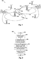
FIG. 1 is a high-level diagram of portions of acommunication system 100 in accordance with one or more embodiments.Communication system 100 can be a wireless communication system or other similar communication system that uses power control techniques and algorithms to control a transmit power of one or more devices transmitting data. As illustrated,FIG. 1 includesbase stations mobile devices Base station 102 generally communicates wirelessly with mobile devices incell 110, whilebase station 104 generally communicates wirelessly with mobile devices incell 112. Base station controller 114 (which in some embodiments can be referred to as an eNode-B or an evolved node-B) is coupled tobase station 102, and perhapsother base stations 116, in order to control the operation ofbase station 102 and other base stations. In various embodiments,base station controller 114 can perform packet scheduling functions, connection mobility control, load balancing, inter Radio-Access-Technology handover, and the like. Similarly,base station controller 118 is coupled tobase station 104, and perhapsother base stations 120, for the purpose of controllingbase station 104. The base station controllers can be coupled to base stations via a communication link that can be wireless, wireline, fiber optic, or the like. The base station controller can be co-located with a base station. -
Communications system 100 can be implemented according to the specification for the long-term evolution (LTE) project within the Third Generation Partnership Project (3GPP) wireless system, which is essentially a wireless packet data system that can transmit voice (e.g., VoIP) and other data. -
Mobile device 106 can communicate withbase station 102 viawireless communication link 122.Mobile device 108 can communicate withbase station 104 viawireless communication link 124. Whenmobile device 106 is near the edge of itsserving cell 110, and also near anothermobile device 108, which is near the edge of itsserving cell 112,interference 126 frommobile device 108 can interfere with transmissions frommobile device 106 inwireless communications link 122, particularly whenmobile device 106 andmobile device 108 have been assigned the same transmission frequency. - In each
cell base stations 102 and 104) can simultaneously receive uplink transmissions from a plurality of mobile devices, such asmobile device 106 and others not shown. In some embodiments, the base station is adapted to receive the wireless uplink transmissions with receive signal strengths that are substantially the same. To make the receive signal strengths substantially the same, an uplink transmit power control algorithm can be used to control the transmit power of each mobile device. In one embodiment, the base station can broadcast a cell-wide power control parameter to all mobile devices in the cell served by the base station.Base station 102 can broadcast, to all mobile devices (e.g., mobile device 106) served bybase station 102, a cell-wide target for received power (i.e., a power control parameter) that is related to the signal to interference-plus-noise ratio (SINR) received at the base station. - The cell-wide power control parameter can be a fractional power control exponent. The fractional power control exponent can be represented as the symbol "α" in Equation 1, below:
mobile_station_poweri = Pmax X min( 1, max(Rmin, (PLi / PLxile)□) (Eqn. 1) where mobile_station_poweri is the power calculated by the ith mobile in the cell, PLxile is the x-percentile of the path-loss from all mobiles in the cell to the base station, Rmin is the minimum power reduction ratio, and PLi is the path loss from the mobile device (or UE) in question to the base station. Using equation 1 above, with 0 < □ < 1, mobile devices at the center of the cell have lower thresholds than those at the edges of the cell, resulting in less interference in the network. - Referring now to
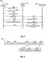
FIG. 2 , there is depicted a "bounce diagram" illustrating messages communicated between various components ofcommunication system 100. As depicted, messages are communicated betweenmobile device 202, servingbase station 204, andbase station controller 206.Base station controller 206 can be implemented withbase station controller 114, as shown inFIG. 1 . Althoughbase station 204 andbase station controller 206 are shown separately, they may or may not be physically co-located, depending upon the system. - Before a mobile device has been synchronized (e.g., when the mobile device is in the idle mode), the mobile device can initiate communication with the serving base station by sending an asynchronous RACH 208 (i.e., an asynchronous random access channel message). The random access channel is typically shared by all mobile devices in a cell served by the base station. Asynchronous RACH 208 preamble can tell
base station 204 thatmobile device 202 has a message for the base station. A request for service on the random access channel can be referred to as a "RACH request." - Asynchronous RACH 208 is initially transmitted at a relatively low power to avoid excessive interference. Therefore,
asynchronous RACH 208 may not be received bybase station 204. Ifasynchronous RACH 208 is not received bybase station 204, there will be no response bybase station 204, andmobile device 202 will resendasynchronous RACH 210 at an incrementally higher power level so that the asynchronous RACH is eventually received bybase station 204, - Upon reception of
asynchronous RACH 210,base station 204 can respond by sendingRACH response 212.RACH response 212 can include a message frombase station 204 that acknowledgesmobile device 202 and further instructsmobile device 202 with regard to signal timing, transmit power, and a time and frequency to use for a next uplink transmission. As an example,RACH response 212 can contain instructions tomobile device 202 to adjust the timing of its transmission by + 1.04 µS, to adjust transmit power by -2 dB, and to send a synch RACH (i.e., a synchronous RACH message) at a particular start frequency, with a particular number of frequencies, and within a particular time interval. - After receiving
RACH response 212,mobile device 202 can respond with asynch RACH message 214 that indicates that the mobile device is requesting a service from the base station. Additionally,mobile device 202 can use a part or segment of the message to indicate that it has a resource utilization limitation, if such a resource utilization limitation exceeds a limitation threshold for reporting to the base station. - The mobile device resource utilization limitation can be a limit to the number of resource blocks that can be used during an uplink transmission relative to a current power level and current modulation and encoding scheme (MCS). In another embodiment, the mobile device resource utilization limitation can be an amount of remaining power (e.g., a power headroom) that can be used for uplink transmission. Thus,
synch RACH message 214 can indicate that the mobile device has a file to be transferred (i.e., requesting file transfer services), and that the mobile device is power limited to 4 resource blocks (i.e., the mobile device resource utilization limitation indicates that the mobile device should not be assigned more than 4 resource blocks, taking into consideration the current transmit power, the maximum transmit power of the mobile device, and the current modulation and coding scheme). - Note that the resource utilization limitation must exceed a limitation threshold before the limit is reported to the base station. This limitation threshold for reporting should be set at a point where device resource utilization limitations are reported when there is a likelihood that an uplink scheduler will schedule an uplink transmission that exceeds the capacity of the mobile device. When the mobile device sends a mobile device resource utilization limitation message, the base station (or other uplink traffic scheduling entity) can use this information to intelligently schedule uplink traffic in a way that does not exceed the transmit power capabilities of the mobile device. For example, if
base station 204 decides to allocate a number of resource blocks greater than the number of blocks that the mobile device has indicated as a limit, the base station can scale back the modulation and coding scheme so that the mobile device can transmit a requested power on all the assigned resource blocks. - With regard to the format of the
synch RACH message 214,FIG. 3 shows an example of the format of the message. As illustrated,message 300 can includeheader 302, aservice request 304, aservice request parameter 306, an optional mobile deviceresource utilization limitation 308, and anerror control field 310.Header 300 can be used to indicate the type of message.Service request 304 can be a field for indicating a request for a service from the base station serving the mobile device. Such a request for service can include a request to transfer a file, a request to place a voice call, a request for email delivery, a request for downloading music or video clips, or the like.Service request parameter 306 can contain information related to the service request, such as a file size for the file transfer, or other similar information needed to complete the service request. - If the threshold for reporting the mobile device utilization limitation has been exceeded, the mobile device
resource utilization limitation 308 portion ofsynch RACH message 214 can include a powerlimited flag 312 that indicates whether it is possible for the mobile device to be scheduled for an uplink communication in a manner that exceeds its power capability. For example, if the flag is set it can indicate that the mobile device is currently operating at a power that is close to its maximum power, which implies that the base station could schedule an uplink transmission for the mobile device that would exceed its power transmission capacity. If the current power of a transmission is 21 dB, and the maximum power transmission is 24 dB, there is a chance that the base station would schedule the mobile device for uplink transmission using four resource blocks, which would require an additional 6 dB of power when only 3 dB of additional power is available before the mobile device reaches maximum power. In this ease wherebase station 204 would like to schedule 4 resource blocks formobile device 202,base station 204 can either limit the maximum number of resource blocks to 2, orbase station 204 can schedule 4 resource blocks and assume thatmobile device 202 will scale the transmit power by 2 (i.e., reduce the power by ½) and use all 4 resource blocks. Note thatbase station 204 can schedule a number of resource blocks exceeding the number of resource blocks reported in the mobile deviceresource utilization limitation 308, because the mobile device can be a better candidate for scheduling than other mobile devices. - In addition to the power
limited flag 312, mobile device resourceutilization limitation field 308 can include a field to indicateresource block capacity 314. Resourceblock capacity field 314 can indicate a maximum number of resource blocks the mobile device can use, or the field can indicate a number of additional blocks that can be used by the mobile device. Present transmitpower field 316 can be used to indicate the present transmit power of the mobile device. If mobile device sends the present transmit power to the base station, the base station can calculate the maximum number of resource blocks that can be used by the mobile device, or the number of additional blocks that can be used by the mobile device. Examples not falling in the scope of the invention of mobile deviceresource limit field 308 can include powerlimited flag 312 and eitherresource block capacity 314 or present transmitpower 316, or both. - Mobile device resource
utilization limitation field 308 can also indicate other limitations of the mobile device. For example, many mobile devices can transmit using one of many different levels of modulation and coding schemes (MCS). If a mobile device does not have all the levels, or if some levels are unavailable because of low battery (or other similarly limiting condition), or because the mobile device is not a full-featured device that implements all the MCS levels, then mobile device resourceutilization limitation field 308 can inform the scheduler of these limitations so that a mobile device is not scheduled to perform an uplink transmission that it cannot accomplish. - In
FIG. 2 , after the mobile device sendssynch RACH message 214 to servingbase station 204, the message is forwarded tobase station controller 206 as shown at 216.Base station controller 206 can respond withdownlink control message 218 sent to servingbase station 204, and forwarded tomobile device 202 as shown at 220, wherein the downlink control message instructsmobile device 202 to sound out the channel at a particular time and frequency.Mobile device 202 can respond by sending an unlinkchannel sounding message 222, where the mobile device transmits known codes or data (e.g., a known data sequence) on a set of subcarriers which are more or less evenly distributed across the channel bandwidth. In some embodiments, the known codes can be pilot sequences embedded in the uplink data channel. Channel sounding is a process for characterizing a channel between the base station and the mobile device. The channel can be characterized by calculating the channel impulse response. - After uplink
channel sounding message 222 has been received bybase station 204,base station 204 prepares a carrier to interference-plus-noise ratio (CINR) and power control (PC)report 224, which is then forwarded tobase station controller 206. CINR is a measurement of signal effectiveness, expressed in decibels (dBs). The carrier is the desired signal, and the interference can include noise, co-channel interference, or other channel interference, or all of these. In order for the signal receiver to decode the signal, the signal must fall into an acceptable CINR range. Co-channel interference is more of a problem when frequencies are reused at short distances. In embodiments where channel sounding is not used in the system,base station 204 can infer the CINR from long term tracking of the channel through the reference symbols of the data channel. - After receiving any mobile device resource utilization limitation, and any mobile-specific power control parameters, such as the data resulting from a channel sounding,
base station controller 206 can prepare and send to base station 204 a grant for aresource allocation 226. Grant forresource allocation 226 is then forwarded tomobile device 202 as shown at 228. - The grant for
resource allocation 226 can either be a grant for a dynamic resource allocation or a grant for a persistent resource allocation. A grant for a dynamic resource allocation is a relatively short term grant that includes a one-time power control instruction for use during the duration of the dynamic resource allocation grant. A grant for a persistent resource allocation is a longer term grant that includes a power control instruction for initial use during the dynamic resource allocation grant, and subsequent power control instructions received periodically during the duration of the persistent resource allocation grant. -
FIG. 4 . is a bounce diagram that depicts messages sent betweenmobile device 202, servingbase station 204, andbase station controller 206, resulting in a grant of a persistent resource allocation in accordance with one or more embodiments. Messages anddata communication 208 through 224 are similar to those discussed above with reference toFIG. 2 . In this example,synch RACH 214 can include a request for a base station service that is best suited for a persistent resource allocation grant. For example,synch RACH 214 can include a request for a voice call. Persistentresource allocation grant 402 is sent frombase station controller 206 tobase station 204, and then forwarded tomobile device 202 as shown at 404. Persistentresource allocation grant 402 can contain a power control instruction for initial use during the persistent resource allocation grant. Subsequent power control instructions can be sent frombase station controller 206, tobase station 204, and tomobile device 202. For example, after a period of timedecrement power instruction 406 follows persistentresource allocation grant 402.Decrement power instruction 406 is forwarded tomobile device 202 as shown at 408 to instructmobile device 202 to reduce its power by a predetermined incremental amount. Followingpower control instruction 406 are additional periodicpower control instructions mobile device 202 has shown at 412 and 416, respectively, for the duration of the persistent resource allocation grant. - Thus, following a dynamic
resource allocation grant 226,mobile device 202 operates in a mode wherein additional power control instructions are not expected frombase station 204. Following a persistentresource allocation grant 402,mobile device 202 operates in a mode wherein additional power control instructions are expected frombase station 204 for the duration of the persistent resource allocation. -
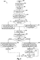
FIG. 5 shows a high-level flowchart of processes that can be executed bymobile device 106 inFIG. 1 , or other systems with appropriate functionality, in accordance with one more embodiments. As shown, the process begins at 502, and thereafter continues at 504 wherein the process sends an asynchronous RACH to the base station. The asynchronous RACH message (such asasynchronous RACH message FIG. 2 .) can be sent from an idle mobile device (e.g. mobile device 106) to the base station (e.g. base station 102) to alert the base station that the mobile device has a message for the base station. - Next, the process receives a RACH response from the base station, as illustrated at 506. The RACH response acknowledges the transmission from the mobile device, and can further instruct the mobile device to adjust its transmission timing and its transmit power, and to respond with a synchronous RACH at a particular time slot and on a particular frequency (e.g., a set of frequencies or resource block).
- After receiving the RACH response, the mobile device determines a mobile device power limitation, as depicted at 508. In one embodiment, this step can be implemented by determining the power headroom of the mobile device, wherein the power headroom is the difference between the power the mobile device was instructed to use in the RACH response and the maximum power of the mobile device.
- Once the mobile device power limitation has been determined, the process determines a mobile device resource utilization limitation based on the power limitation, as illustrated at 510. This step can be implemented by determining a maximum number of resource blocks that can be used by the mobile device in an uplink transmission based on the power headroom. For example, in one embodiment, if the mobile device has currently been instructed to transmit at 21 dBm, and the maximum power for the mobile device is 24 dBm, which makes the power headroom 3 dB, and the maximum number of resource blocks that can be used by the mobile device would be 2, since adding a second resource block requires twice the power, which is an additional 3 dB increase in power.
- Next, the process determines whether the mobile device resource utilization limitation exceeds a reporting threshold, as depicted at 512. The reporting threshold can be set to a level that prevents mobile devices that are not limited by their power headroom from reporting the mobile device power limitation. Mobile devices that are not limited by their power headroom can save the bandwidth needed to report the resource utilization limitation because the scheduler in the base station (or base station controller) does not need to be concerned with limiting scheduled resources to a mobile device that is not limited by power headroom. Conversely, if a mobile device is limited by its power headroom, the scheduler needs to know, preferably in advance of scheduling, so that it will not schedule a resource allocation that will exceed the mobile device's transmit power capability.
- If the resource utilization limitation exceeds the reporting threshold, the process passes to 514 wherein the process sends a synch RACH (such as
sync RACH 214 shown inFIG. 4 ) to the base station, where in the synch RACH includes a resource allocation request and the resource utilization limitation. The resource allocation request can include a request for a file transfer, a request for a voice call, a request for a video or music file, or the like. The resource utilization limitation can include a maximum number of resource blocks, a maximum level of modulation and coding, or other similar resource limits that depend upon the mobile device transmit power. Note that the resource utilization limitation parameter can be transmitted on a dedicated message, and does not have to be piggy-backed on the sync RACH message. - If the resource utilization limitation does not exceed the reporting threshold, the process passes to 516 wherein the mobile device sends a synch RACH to the base station that includes a resource allocation request, but no resource utilization limitation.
- After the synch RACH message is sent to the base station, the process can receive a channel sounding command, as illustrated at 518. In response to the channel sounding command, the process sends a channel sounding data sequence, as depicted 520. The channel sounding data sequence is a known data sequence, which is transmitted at a known transmit power on preselected frequencies across the bandwidth of the communication system. Channel sounding gives the base station and/or the base station controller data that represents the quality of the channel on the various frequencies across the spectrum. This information is useful in scheduling uplink transmissions from the mobile devices because the scheduler prefers to grant resources to mobile devices that are presently capable of using those resources with desirable channel conditions. In embodiments where channel sounding is not used in the system,
base station 204 can infer the CINR from long term tracking of the channel through the reference symbols of the data channel. - After sending the channel sounding sequence, the process receives a dynamic or a persistent resource allocation grant, and determines whether the grant was dynamic or persistent at 522. If the grant was dynamic, the process receives instructions for a dynamic uplink transmission, including a power control instruction for use during the duration of the dynamic resource grant, as depicted at 524. The process then transmits on the uplink according to the dynamic resource allocation grant as shown at 526, and uses the power control instruction to set the transmit power for the duration of the grant. At the end of data transmission according to the dynamic resource allocation grant, the process ends as depicted at 536.
- Alternatively, if the grant was persistent, the process receives instructions for a persistent uplink transmission, including an initial power control instruction to begin the persistent resource grant transmission, as illustrated at 528. The process then transmits on the uplink according to the persistent resource allocation grant, and uses the initial power control instruction to start the persistent grant transmission, as shown at 530. After a period of time, the process receives an additional power control instruction, as depicted at 532.
- Next, the process determines whether the persistent grant has expired, as illustrated at 534. If the persistent grant has not expired, the process continues to send more data at 530, and periodically receives updated power control instructions at 532.
- If the persistent grant has expired, the process of transmitting on the allocated uplink resource according to the persistent resource grant ends, as shown at 536.
-
FIG. 6 shows a high-level flowchart of processes that can be executed bymobile device 106 inFIG. 1 , or other systems with appropriate functionality, in accordance with one or more examples not falling in the scope of the invention. As illustrated, the process begins at 602, and thereafter continues at 604 wherein the process receives a cell-wide power control parameter. The cell-wide power control parameter is a parameter that is sent to all mobile devices in the cell by the serving base station. The parameter can be sent by a broadcast channel. In one example not falling in the scope of the invention, the cell-wide power control parameter is a cell target signal to interference-plus-noise ratio (SINK) received at the base station (e.g., base station 102). In another example not falling in the scope of the invention, the cell-wide power control parameter can be a fractional power control exponent, which is shown as symbol "α" in Equation 1 above. - After receiving the cell-wide power control parameter, the process determines an implicit mobile-specific power control parameter that is related to a target receive power at a serving base station, as illustrated at 606. An implicit mobile-specific power control parameter is a parameter related to uplink power control that is specific to the mobile device (i.e., a parameter that is not broadcast) and that is implied by other messages or commands sent to the mobile device, or measurements made by the mobile device, which makes the implicit parameter one that does not require additional message traffic from the base station. In one example not falling in the scope of the invention, the implicit mobile-specific power control parameter can be a modulation and coding level previously used by the mobile device. The modulation and coding level is sent to the mobile device by the base station, and it implicitly indicates the uplink channel characteristics between the mobile device and the base station. In one example not falling in the scope of the invention, the modulation and coding level previously used by the mobile device can be an average modulation and coding level averaged over a time window.
- In another example not falling in the scope of the invention, the implicit mobile-specific power control parameter can be a downlink SINR level (or an averaged downlink SINR level) measured by the mobile device. In a time domain duplex (TDD) communication system, by the reciprocity principle, the downlink SINR implicitly indicates the uplink channel characteristics. In a frequency domain duplex (FDD) communication system, the uplink and downlink channel fast fading components may be uncorrelated even though the pathloss and shadowing components are identical. Averaging the downlink SINR over time and frequency will average out the fading components and provide a good implicit estimate of the uplink channel characteristics.
- In some examples not falling in the scope of the invention, the mobile device can also receive a mobile-specific power control parameter, in addition to the cell-wide power control parameter and the implicit mobile-specific power control parameter. The mobile-specific power control parameter can be received in a message from the base station that is directed specifically to the mobile device. In the ease where the mobile device receives a cell-wide power control parameter and a mobile-specific powerful parameter, the implicit mobile-specific power control parameter can be a correlation between the mobile-specific power control parameter and a modulation and coding level assigned by the serving base station. Thus, the implicit mobile-specific power control parameter can vary between the case where the mobile-specific power control parameter correlates directly with the modulation and coding scheme and in the case where the mobile-specific power control parameter correlates in directly with the modulation and decoding scheme. As an example, a direct correlation between the power control parameter and the modulation and coding scheme is where the mobile device receives a relatively high power in combination with a relatively high modulation and coding level (i.e., a modulation and coding level that requires a higher power), and similarly the case where the mobile device receives a relatively low power in combination with a relatively low modulation and coding level. An example of an indirect correlation between the power control parameter and the modulation and coding scheme is where the mobile device receives a relatively high power in combination with a relatively low modulation and coding scheme, and vice versa. Thus, this implicit mobile-specific correlation factor varies between expected power levels
and modulation and coding schemes, and unexpected combinations of power level and modulation and coding schemes. - Next, the process calculates the mobile device uplink transmit power using the cell-wide power control parameter and the implicit mobile-specific power control parameter, as depicted at 608. In this step, the implicit mobile-specific power control parameter is used to adjust a transmitter power indicated by the cell-wide power control parameter, or to adjust a transmit power indicated by the cell-wide power control parameter in combination with a mobile-specific power control parameter. In one example not falling in the scope of the invention, this adjustment can be a percentage of the transmit power indicated by calculations using cell-wide parameters, or by calculations using cell-wide parameters in combination with mobile-specific parameters.
- As an example, assume that the base station broadcasts a cell-wide target SINR that maps to an average MCS level of 16 QAM (i.e., 16 point constellation, quadrature amplitude modulation) (SINR16) with coding rate ½. The mobile device will first calculate its transmit power to ensure that its signal is received at the base station with the cell-wide target S1NR16. Then, the mobile device can autonomously calculate a correction factor based upon an implicit mobile-specific power control parameter, such as a history of uplink MCS allocated to the mobile device. If the mobile device observes that its average MCS level allocated over time and frequency is 4 QAM rate ½, which maps to an average SINR received at the base station of SINR4, a correction factor of SINR16 - SINR4 can be autonomously applied by the mobile device to bring it in line with the expected received SINR16, at the base station. Thus, the difference between the target SINR and the implied SINR determines the addition (if the measured MCS implies a lower SINR at the base station) or subtraction (if the measured MCS implies a higher SINR at the base station) of an autonomous correction factor.
- In one example not falling in the scope of the invention, the difference (i.e., the correction factor) can be applied directly to the transmit power at one time. In another example not falling in the scope of the invention the correction factor can be incrementally applied over a period, either by applying a number of fixed incremental corrections (e.g., change by 1 dB), or by applying a percentage of the correction factor over a fixed number of corrections (e.g., change by 20% of the correction factor over 5 changes). The correction factor can be periodically recalculated, even before a previous correction factor is completely applied.
- Furthermore, the mobile device can make continuous measurements on the downlink SINR levels and average the measurements over time and frequency to estimate a long term downlink received SINR. This estimated long term SINR can then be compared to the uplink SINR the mobile device expects based on the autonomously corrected transmit power as calculated in the example above. A delta correction factor can be calculated and applied based on the difference, and the delta correction factor can then be used in the calculation of the autonomous correction factor to increase its accuracy. The delta correction factor can be used to compensate for inaccuracies in transmit power, which are due to a difference in a set transmit power and an actual transmit power in the mobile device.
- After calculating the mobile device uplink transmit power, the mobile device transmits data using the transmit power, as illustrated at 610. The data is transmitted on the time and frequency indicated by a resource allocation grant. After transmitting the data using the calculated transmit power, the process ends at 612.
- If the mobile device has been granted a resource allocation that cannot be fulfilled in the transmission at 612 because of power limitations in the mobile device (e.g., a combination of transmit power and MCS cannot be achieved because the combination exceeds the maximum power of the mobile device), the mobile device has several options: (1) the mobile device can transmit using a lower power; (2) the mobile device can transmit using a lower MCS level; (3) the mobile device can transmit on a reduced number of resource blocks; (4) the mobile device can repeat the request for resource allocation (e.g., repeat the synch RACH message 214), wherein the repeated request includes an indication of the resource utilization limitation (e.g., 308), which limitation caused the previous grant to exceed the mobile device power limitation.
- Although the invention is described herein with reference to specific embodiments, various modifications and changes can be made without departing from the scope of the present invention as set forth in the claims below. For example, while the techniques and apparatus for controlling a transmit power in a mobile device may vary widely, one or more embodiments can be used in a system operating according to the 3GPP LTE standard. Accordingly, the specification and figures are to be regarded in an illustrative rather than a restrictive sense, and all such modifications are intended to be included within the scope of the present invention. Any benefits, advantages, or solutions to problems that are described herein with regard to specific embodiments are not intended to be construed as a critical, required, or essential feature or element of any or all the claims. The intended limitations are defined by the claims.
- Unless stated otherwise, terms such as "first" and "second" are used to arbitrarily distinguish between the elements such terms describe. Thus, these terms are not necessarily intended to indicate temporal or other prioritization of such elements.
Claims (13)
- A method for wireless communication power control comprising:receiving a resource allocation request, where the resource allocation request is based on a power limitation of a wireless device (106);at a first time, sending a dynamic power control instruction for execution by the wireless device (106) during a duration of a dynamic resource allocation grant sent from a base station (102); andat a second time, sending an initial power control instruction for initial execution by the wireless device (106) during a duration of a persistent resource allocation grant sent from the base station (102), and sending subsequent power control instructions for subsequent execution by the wireless device (106) during the duration of the persistent resource allocation grant.
- The method of claim 1, wherein the sending subsequent power control instructions comprises sending adjustment instructions, wherein the adjustment instructions include one or more of an instruction to increment power and an instruction to decrement power.
- The method of claim 1, further comprising:sending a channel sounding request; andreceiving a channel sounding message in response to the channel sounding request.
- The method of claim 3, wherein the resource allocation of at least one of the dynamic resource allocation grant and persistent resource allocation grant is based on data resulting from the channel sounding message and the resource allocation request.
- The method of claim 1, wherein the resource allocation request is received in response to a resource utilization limitation of the mobile device (106) exceeding a reporting threshold, wherein the resource utilization limitation is based on the power limitation.
- The method of claim 5, wherein resource utilization limitation is a power headroom.
- The method of claim 1, further comprising reducing a transmit power for the wireless device (106) when an allocated number of resource blocks exceeds the maximum number of resource blocks for the wireless device (106), wherein the maximum number of resource blocks corresponds to a maximum power of the wireless device.
- A base station (102), comprising:a receiver configured to receive a resource allocation request based on a power limitation of a wireless device (106);a transmitter configured to:at a first time, send a dynamic power control instruction for execution by the wireless device (106) during a duration of a dynamic resource allocation grant sent from the base station (102); andat a second time, sending an initial power control instruction for initial execution by the wireless device (106) during a duration of a persistent resource allocation grant sent from the base station (102), and sending subsequent power control instructions for subsequent execution by the wireless device (106) during the duration of the persistent resource allocation grant.
- The base station of claim 8, wherein, in sending subsequent power control instructions, the transmitter is configured to send adjustment instructions, wherein the adjustment instructions include one or more of an instruction to increment power and an instruction to decrement power.
- The base station of claim 8, wherein:the transmitter is further configured to send a channel sounding request; andthe receiver is further configured to receive a channel sounding message in response to the channel sounding request.
- The base station of claim 10, wherein the resource allocation of at least one of the dynamic resource allocation grant and persistent resource allocation grant is based on data resulting from the channel sounding message and the resource allocation request.
- The base station of claim 8, wherein, the receiver is configured to receive the resource allocation request in response to a resource utilization limitation of the mobile device (106) exceeding a reporting threshold, wherein the resource utilization limitation is based on the power limitation.
- The base station of claim 12, wherein the resource utilization limitation is a power headroom.
Priority Applications (1)
| Application Number | Priority Date | Filing Date | Title |
|---|---|---|---|
| PL19152129T PL3490312T3 (en) | 2007-03-19 | 2008-02-25 | Resource allocation in a communication system |
Applications Claiming Priority (4)
| Application Number | Priority Date | Filing Date | Title |
|---|---|---|---|
| US11/725,423 US9295003B2 (en) | 2007-03-19 | 2007-03-19 | Resource allocation in a communication system |
| PCT/US2008/054823 WO2008115660A1 (en) | 2007-03-19 | 2008-02-25 | Resource allocation in a communication system |
| EP13185604.9A EP2680629B1 (en) | 2007-03-19 | 2008-02-25 | Resource allocation in a communication system |
| EP08730594.2A EP2137994B1 (en) | 2007-03-19 | 2008-02-25 | Resource allocation in a communication system |
Related Parent Applications (3)
| Application Number | Title | Priority Date | Filing Date |
|---|---|---|---|
| EP08730594.2A Division EP2137994B1 (en) | 2007-03-19 | 2008-02-25 | Resource allocation in a communication system |
| EP13185604.9A Division EP2680629B1 (en) | 2007-03-19 | 2008-02-25 | Resource allocation in a communication system |
| EP13185604.9A Division-Into EP2680629B1 (en) | 2007-03-19 | 2008-02-25 | Resource allocation in a communication system |
Publications (2)
| Publication Number | Publication Date |
|---|---|
| EP3490312A1 EP3490312A1 (en) | 2019-05-29 |
| EP3490312B1 true EP3490312B1 (en) | 2022-01-12 |
Family
ID=39766322
Family Applications (3)
| Application Number | Title | Priority Date | Filing Date |
|---|---|---|---|
| EP13185604.9A Active EP2680629B1 (en) | 2007-03-19 | 2008-02-25 | Resource allocation in a communication system |
| EP08730594.2A Active EP2137994B1 (en) | 2007-03-19 | 2008-02-25 | Resource allocation in a communication system |
| EP19152129.3A Active EP3490312B1 (en) | 2007-03-19 | 2008-02-25 | Resource allocation in a communication system |
Family Applications Before (2)
| Application Number | Title | Priority Date | Filing Date |
|---|---|---|---|
| EP13185604.9A Active EP2680629B1 (en) | 2007-03-19 | 2008-02-25 | Resource allocation in a communication system |
| EP08730594.2A Active EP2137994B1 (en) | 2007-03-19 | 2008-02-25 | Resource allocation in a communication system |
Country Status (7)
| Country | Link |
|---|---|
| US (5) | US9295003B2 (en) |
| EP (3) | EP2680629B1 (en) |
| JP (4) | JP5351776B2 (en) |
| KR (7) | KR101637150B1 (en) |
| CN (2) | CN102711231A (en) |
| PL (1) | PL3490312T3 (en) |
| WO (1) | WO2008115660A1 (en) |
Families Citing this family (78)
| Publication number | Priority date | Publication date | Assignee | Title |
|---|---|---|---|---|
| KR100853699B1 (en) * | 2006-12-01 | 2008-08-25 | 한국전자통신연구원 | Method of controllong call setup in wireless communication system |
| US7881721B2 (en) * | 2007-04-30 | 2011-02-01 | Freescale Semiconductor, Inc. | Channel sounding techniques for a wireless communication system |
| JP5118894B2 (en) * | 2007-06-05 | 2013-01-16 | 株式会社Kddi研究所 | Wireless base station |
| EP2171871B1 (en) * | 2007-06-20 | 2019-04-17 | Cellular Communications Equipment Llc | Power headroom reporting method |
| JP5080645B2 (en) | 2007-07-04 | 2012-11-21 | テレフオンアクチーボラゲット エル エム エリクソン(パブル) | User terminal power shortage display |
| US8169992B2 (en) | 2007-08-08 | 2012-05-01 | Telefonaktiebolaget Lm Ericsson (Publ) | Uplink scrambling during random access |
| MX2010002747A (en) * | 2007-09-11 | 2011-02-25 | Wi Lan Inc | Error correction for a persistent resource allocation. |
| US8300716B1 (en) | 2007-12-26 | 2012-10-30 | Marvell International Ltd. | Link adaptation for OFDM systems |
| US8199719B2 (en) | 2008-03-13 | 2012-06-12 | Apple Inc. | Methods and apparatus for performing handover between a long term evolution (LTE) network and another type of radio access network |
| WO2009129613A1 (en) | 2008-04-21 | 2009-10-29 | Nortel Networks Limited | Method and system for providing an uplink structure and minimizing pilot signal overhead in a wireless communication network |
| WO2009153808A2 (en) * | 2008-06-17 | 2009-12-23 | Centre Of Excellence In Wireless Technology | Methods and systems for interference mitigation |
| KR101313703B1 (en) | 2008-06-20 | 2013-10-01 | 닛본 덴끼 가부시끼가이샤 | Resource allocation method, identification method, base station, and mobile station |
| EP3567790B1 (en) * | 2008-06-20 | 2023-09-06 | NEC Corporation | Resource allocation method and apparatus |
| US8046022B2 (en) * | 2008-07-08 | 2011-10-25 | Wi-Lan, Inc. | Signal transmission parameter control using channel sounding |
| KR20100048844A (en) * | 2008-10-31 | 2010-05-11 | 삼성전자주식회사 | Apparatus and method for uplink power control in wireless communiation system |
| TWI542241B (en) | 2008-12-03 | 2016-07-11 | 內數位專利控股公司 | Method and apparatus for reporting power headroom |
| KR101697596B1 (en) | 2009-01-29 | 2017-01-18 | 엘지전자 주식회사 | Method and apparatus of controlling transmission power |
| US8572271B2 (en) * | 2009-01-29 | 2013-10-29 | Qualcomm Incorporated | Multimedia management system for seamless multimedia content mobility |
| EP2415314A1 (en) * | 2009-04-03 | 2012-02-08 | Telefonaktiebolaget LM Ericsson (publ) | Uplink link adaption at the user equipment |
| KR101083482B1 (en) | 2009-04-16 | 2011-11-16 | 주식회사 세아네트웍스 | Apparatus and Method for Reporting Transmission Power, and Apparatus and Method for Determining Transmission Power |
| US8824424B2 (en) * | 2009-04-21 | 2014-09-02 | Blackberry Limited | System and method for adjusting monitoring of timeslots during data transmission |
| JP5023170B2 (en) * | 2009-04-27 | 2012-09-12 | 株式会社エヌ・ティ・ティ・ドコモ | User apparatus, base station apparatus, and communication control method |
| WO2010127725A1 (en) * | 2009-05-07 | 2010-11-11 | Telefonaktiebolaget Lm Ericsson (Publ) | Managing a power consumption of a mobile communication device |
| US9634806B2 (en) * | 2009-06-11 | 2017-04-25 | Qualcomm Incorporated | Data prioritization for a power-limited UE in a wireless communication system |
| KR101517170B1 (en) | 2009-09-29 | 2015-05-04 | 삼성전자주식회사 | Apparatus and method for reducing power comsumption in multi antenna system |
| MX2012003894A (en) | 2009-10-01 | 2012-07-25 | Interdigital Patent Holdings | Power control methods and apparatus. |
| US8768397B2 (en) | 2009-10-02 | 2014-07-01 | Sharp Kabushiki Kaisha | Transmission power control on a wireless communication device for a plurality of regulated bands or component carriers |
| US9059749B2 (en) | 2009-10-02 | 2015-06-16 | Sharp Kabushiki Kaisha | Antenna port mode and transmission mode transitions |
| EP2491740A1 (en) * | 2009-10-23 | 2012-08-29 | Telefonaktiebolaget L M Ericsson (PUBL) | Arrangements and methods in communication nodes |
| EP2494824A1 (en) * | 2009-10-29 | 2012-09-05 | Nokia Siemens Networks Oy | Method and device for adjusting an uplink transmission power of a mobile terminal |
| CN101711058B (en) * | 2009-12-15 | 2012-12-05 | 中兴通讯股份有限公司 | Resource allocation method and resource allocation system |
| US8488562B2 (en) * | 2009-12-18 | 2013-07-16 | Qualcomm Incorporated | Transmission power control in multi-hop networks |
| US8437794B2 (en) * | 2010-01-28 | 2013-05-07 | Alcatel Lucent | Methods of determining uplink target signal-to-interfence-and-noise ratios and systems thereof |
| US20120300616A1 (en) * | 2010-02-02 | 2012-11-29 | Nokia Corporation | Methods and Apparatuses for Resource Mapping for Multiple Transport Blocks Over Wireless Backhaul Link |
| JP4913222B2 (en) | 2010-02-12 | 2012-04-11 | シャープ株式会社 | Wireless communication system, mobile station apparatus, wireless communication method, and integrated circuit |
| EP2364051B1 (en) * | 2010-03-03 | 2017-05-03 | BlackBerry Limited | Method and apparatus to indicate space requirements for communicating capabilities of a device |
| EP2367393B8 (en) * | 2010-03-12 | 2015-12-30 | BlackBerry Limited | Communication Station and Method for Transmitting Additional Information on an Enhanced Random Access Channel |
| EP3007500B1 (en) * | 2010-03-12 | 2022-05-04 | BlackBerry Limited | Communication station and method for transmitting on a random access channel |
| EP3755075A3 (en) | 2010-03-12 | 2021-03-31 | BlackBerry Limited | Timing advance enhancements for cellular communications |
| EP2367394B1 (en) | 2010-03-12 | 2015-11-25 | BlackBerry Limited | Base station and method for receiving transmissions on an enhanced random access channel |
| CN105007148B (en) | 2010-04-01 | 2018-07-20 | Lg电子株式会社 | The method and apparatus of report/reception power climbing space value in wireless access system |
| KR101725553B1 (en) | 2010-04-01 | 2017-04-27 | 엘지전자 주식회사 | Method of performing communication in wireless communication system and apparatus thereof |
| KR20110119578A (en) * | 2010-04-27 | 2011-11-02 | 엘지에릭슨 주식회사 | Small base station and uplink power control method thereof |
| US8644997B2 (en) * | 2010-05-10 | 2014-02-04 | Hamilton Sundstrand Corporation | Load sharing architecture for redundant channel controllers |
| EP2606686B1 (en) * | 2010-08-16 | 2019-03-13 | Telefonaktiebolaget LM Ericsson (publ) | Method and apparatuses for power control using variable step size |
| KR101691038B1 (en) * | 2010-12-10 | 2016-12-30 | 삼성전자주식회사 | Apparatus and method for managing resource of base station in wireless communication system |
| US20130046889A1 (en) * | 2011-08-15 | 2013-02-21 | Alcatel-Lucent Usa Inc. | Methods and apparatuses for scheduling users in wireless networks |
| CN103891166A (en) | 2011-09-30 | 2014-06-25 | 交互数字专利控股公司 | Multipoint transmission in wireless communication |
| US9112267B2 (en) * | 2011-10-11 | 2015-08-18 | Alcatel Lucent | Method of accessing a wireless network and a wireless device |
| CN103052074A (en) * | 2011-10-12 | 2013-04-17 | 中兴通讯股份有限公司 | Method and device for reducing uplink co-channel interference |
| US9332505B2 (en) * | 2011-11-11 | 2016-05-03 | Telefonaktiebolaget L M Ericsson (Publ) | Methods and apparatus for performing measurements in adaptive downlink power transmission |
| CN103167622B (en) * | 2011-12-15 | 2016-04-06 | 展讯通信(上海)有限公司 | Scheduling authorization method and device, the network equipment |
| US10039116B1 (en) | 2012-04-02 | 2018-07-31 | Sprint Communications Company L.P. | Long term evolution scheduler to mitigate interference |
| US9553680B1 (en) | 2012-04-02 | 2017-01-24 | Sprint Communications Company L.P. | Uplink interference mitigation |
| US9300431B2 (en) * | 2012-06-04 | 2016-03-29 | Alcatel Lucent | Apparatus, method and computer readable medium for payload segmentation of wireless packet data transmissions |
| EP2870712B1 (en) * | 2012-07-03 | 2018-09-05 | Telefonaktiebolaget LM Ericsson (publ) | Method and access point for assigning sounding resources |
| CN103874181B (en) * | 2012-12-10 | 2017-05-31 | 中国移动通信集团设计院有限公司 | A kind of is the method and apparatus of terminal distribution down channel |
| EP2982194A1 (en) | 2013-04-03 | 2016-02-10 | Interdigital Patent Holdings, Inc. | Method and apparatus for controlling uplink transmission power based on accumulated transmit power control commands and corresponding uplink subframe sets |
| US20150038140A1 (en) * | 2013-07-31 | 2015-02-05 | Qualcomm Incorporated | Predictive mobility in cellular networks |
| US9807699B2 (en) * | 2013-09-13 | 2017-10-31 | Interdigital Patent Holdings, Inc. | Clear channel assessment (CCA) threshold adaptation method |
| US9585106B2 (en) * | 2014-03-27 | 2017-02-28 | Taiwan Semiconductor Manufacturing Company, Ltd. | Network-assisted channel selection and power control for mobile devices |
| EP3136797B1 (en) * | 2014-04-20 | 2019-07-10 | LG Electronics Inc. | Method for determining transmission power for direct communication between terminals in wireless communication system, and apparatus for same |
| KR102301828B1 (en) | 2014-05-02 | 2021-09-14 | 삼성전자 주식회사 | Method and apparatus for real time transmission power control in wireless communication system |
| US9871578B2 (en) * | 2014-07-30 | 2018-01-16 | Hughes Network Systems, Llc | Clear sky determination in uplink power control using dual time constants |
| US9854527B2 (en) * | 2014-08-28 | 2017-12-26 | Apple Inc. | User equipment transmit duty cycle control |
| JP6459100B2 (en) * | 2015-01-26 | 2019-01-30 | 華為技術有限公司Huawei Technologies Co.,Ltd. | Method and apparatus for selecting a control channel |
| US11252190B1 (en) * | 2015-04-23 | 2022-02-15 | Amazon Technologies, Inc. | Limited access policy bypass |
| CN108574955B (en) * | 2017-03-07 | 2023-04-14 | 中兴通讯股份有限公司 | Method and device for measurement optimization in mobility scene based on UE trigger |
| CN110651521B (en) * | 2017-05-18 | 2023-08-11 | Lg电子株式会社 | Method for allocating resources for signals by terminal in wireless communication system and apparatus therefor |
| KR102098030B1 (en) * | 2017-12-11 | 2020-04-07 | 주식회사 딕스젠 | Composition for Tuberculosis Diagnosis and Diagnostic Method for Tuberculosis based on Optical Properties |
| US10616136B2 (en) * | 2018-04-19 | 2020-04-07 | Microsoft Technology Licensing, Llc | Utilization based dynamic resource allocation |
| US10432798B1 (en) | 2018-05-25 | 2019-10-01 | At&T Intellectual Property I, L.P. | System, method, and apparatus for service grouping of users to different speed tiers for wireless communication |
| US10419943B1 (en) | 2018-06-15 | 2019-09-17 | At&T Intellectual Property I, L.P. | Overlay of millimeter wave (mmWave) on citizens broadband radio service (CBRS) for next generation fixed wireless (NGFW) deployment |
| US10798537B2 (en) * | 2018-07-09 | 2020-10-06 | At&T Intellectual Property I, L.P. | Next generation fixed wireless qualification tool for speed-tier based subscription |
| US11265876B2 (en) * | 2018-08-10 | 2022-03-01 | Qualcomm Incorproated | Uplink power modification and communication scheme change requests |
| KR102562310B1 (en) | 2018-09-27 | 2023-08-01 | 삼성전자주식회사 | Wireless communication apparatus adaptively changing capability and method of operation thereof |
| CN112020140B (en) * | 2019-05-29 | 2023-05-09 | 中国移动通信有限公司研究院 | Resource allocation method and device and communication equipment |
| CN111342881B (en) * | 2020-02-05 | 2021-06-29 | 北京邮电大学 | Method and system for carrying out relay auxiliary transmission based on unmanned aerial vehicle |
Family Cites Families (65)
| Publication number | Priority date | Publication date | Assignee | Title |
|---|---|---|---|---|
| JPH07212404A (en) | 1994-01-26 | 1995-08-11 | Furukawa Electric Co Ltd:The | Inter-network data repeater |
| FI103555B1 (en) * | 1996-06-17 | 1999-07-15 | Nokia Mobile Phones Ltd | Transmission power control in wireless packet data transmission |
| US5982760A (en) | 1997-06-20 | 1999-11-09 | Qualcomm Inc. | Method and apparatus for power adaptation control in closed-loop communications |
| US6154450A (en) | 1997-08-22 | 2000-11-28 | Telefonaktiebolaget Lm Ericsson | Signaling method for CDMA quality based power control |
| US6285665B1 (en) | 1997-10-14 | 2001-09-04 | Lucent Technologies Inc. | Method for establishment of the power level for uplink data transmission in a multiple access system for communications networks |
| GB9724046D0 (en) | 1997-11-14 | 1998-01-14 | Northern Telecom Ltd | Up link power for fixed wireless access |
| JP3058270B2 (en) * | 1998-04-22 | 2000-07-04 | 日本電気株式会社 | CDMA communication method, spread spectrum communication system, base station, and terminal device |
| US6256483B1 (en) * | 1998-10-28 | 2001-07-03 | Tachyon, Inc. | Method and apparatus for calibration of a wireless transmitter |
| US6628956B2 (en) | 1999-03-15 | 2003-09-30 | Telefonaktiebolaget Lm Ericsson (Publ) | Adaptive power control in a radio communications systems |
| EP1054518B1 (en) | 1999-05-21 | 2004-04-28 | Alcatel Alsthom Compagnie Generale D'electricite | A method for improving performances of a mobile radiocommunication system using power control |
| KR100605978B1 (en) | 1999-05-29 | 2006-07-28 | 삼성전자주식회사 | Transceiver apparatus and method for continuous outer loop power control in dtx mode of cdma mobile communication system |
| US6519705B1 (en) | 1999-12-15 | 2003-02-11 | At&T Corp. | Method and system for power control in wireless networks using interference prediction with an error margin |
| US20020091991A1 (en) * | 2000-05-11 | 2002-07-11 | Castro Juan Carlos | Unified real-time microprocessor computer |
| US7023824B2 (en) * | 2001-02-27 | 2006-04-04 | Telefonaktiebolaget L M Ericsson (Publ) | Method, apparatus, and system for optimizing transmission power and bit rate in multi-transmission scheme communication systems |
| US6836666B2 (en) | 2001-05-08 | 2004-12-28 | Lucent Technologies Inc. | Method to control uplink transmissions in a wireless communication system |
| US6587697B2 (en) | 2001-05-14 | 2003-07-01 | Interdigital Technology Corporation | Common control channel uplink power control for adaptive modulation and coding techniques |
| US7584418B2 (en) * | 2001-05-31 | 2009-09-01 | Oracle International Corporation | Methods, systems, and articles of manufacture for prefabricating an information page |
| US7570656B2 (en) * | 2001-06-18 | 2009-08-04 | Yitran Communications Ltd. | Channel access method for powerline carrier based media access control protocol |
| KR100747524B1 (en) * | 2001-07-07 | 2007-08-08 | 엘지전자 주식회사 | Method for controlling signal power in variable data rate mode |
| US7096034B2 (en) * | 2001-10-01 | 2006-08-22 | Microsoft Corporation | System and method for reducing power consumption for wireless communications by mobile devices |
| US6952591B2 (en) | 2001-11-20 | 2005-10-04 | Lucent Technologies Inc. | Uplink power control algorithm |
| KR100911138B1 (en) * | 2002-04-25 | 2009-08-06 | 삼성전자주식회사 | Power controllable wireless mobile communication system of adaptive modulation and coding scheme and its method therefor |
| US6944461B2 (en) * | 2002-06-03 | 2005-09-13 | Lucent Technologies Inc. | Communication system and method for quality-based call admission control and scheduling |
| US8095620B2 (en) * | 2002-06-13 | 2012-01-10 | Elbit Systems Land and C41-Tadiran Ltd. | System and method for dynamic allocation of a resource |
| US6850771B2 (en) | 2002-06-24 | 2005-02-01 | Qualcomm Incorporated | Uplink power control |
| EP1437912B1 (en) * | 2003-01-04 | 2010-09-08 | Samsung Electronics Co., Ltd. | Method for determining data rate of user equipment supporting EUDCH service |
| US8165148B2 (en) * | 2003-01-13 | 2012-04-24 | Qualcomm Incorporated | System and method for rate assignment |
| US20040179469A1 (en) * | 2003-03-13 | 2004-09-16 | Attar Rashid Ahmed | Method and system for a data transmission in a communication system |
| US7746816B2 (en) * | 2003-03-13 | 2010-06-29 | Qualcomm Incorporated | Method and system for a power control in a communication system |
| US20070050777A1 (en) * | 2003-06-09 | 2007-03-01 | Hutchinson Thomas W | Duration of alerts and scanning of large data stores |
| US6970437B2 (en) * | 2003-07-15 | 2005-11-29 | Qualcomm Incorporated | Reverse link differentiated services for a multiflow communications system using autonomous allocation |
| US20050078651A1 (en) * | 2003-08-16 | 2005-04-14 | Samsung Electronics Co., Ltd. | Method and apparatus for assigning scheduling for uplink packet transmission in a mobile communication system |
| KR101000391B1 (en) * | 2003-09-01 | 2010-12-13 | 엘지전자 주식회사 | method of controlling data rate over reverse link |
| US7984108B2 (en) * | 2003-10-08 | 2011-07-19 | Unisys Corporation | Computer system para-virtualization using a hypervisor that is implemented in a partition of the host system |
| CN100353806C (en) * | 2004-04-01 | 2007-12-05 | 大唐移动通信设备有限公司 | Relay switch-over method in TD-SCDMA mobile communication system |
| WO2006010958A2 (en) * | 2004-07-30 | 2006-02-02 | Andrew Richardson | Power control in a local network node (lnn) |
| WO2006020568A1 (en) * | 2004-08-11 | 2006-02-23 | Interdigital Technology Corporation | Channel sounding for improved system performance |
| KR100725773B1 (en) * | 2004-08-20 | 2007-06-08 | 삼성전자주식회사 | Apparatus and method for adaptively changing the uplink power control scheme depending on the status of mobile station in a wireless mobile communication system using time division duplexing scheme |
| CN100382455C (en) * | 2004-10-15 | 2008-04-16 | 中兴通讯股份有限公司 | Method for controlling up going admission based on actual measured quantity in CDMA system |
| DE602006000276T2 (en) * | 2005-02-09 | 2008-11-06 | Ntt Docomo, Inc. | A radio resource allocation method for the uplink, radio base station, and radio network control unit |
| US20060203724A1 (en) | 2005-03-08 | 2006-09-14 | Donna Ghosh | Multi-carrier, multi-flow, reverse link medium access control for a communication system |
| US7499462B2 (en) * | 2005-03-15 | 2009-03-03 | Radiospire Networks, Inc. | System, method and apparatus for wireless delivery of content from a generalized content source to a generalized content sink |
| DE602005011101D1 (en) * | 2005-04-01 | 2009-01-02 | Panasonic Corp | Scheduling of terminals in a radio communication system |
| US20060268764A1 (en) * | 2005-05-26 | 2006-11-30 | Harris John M | Method, apparatus and system for use in allocating reverse channel resources |
| US8744465B2 (en) * | 2005-06-16 | 2014-06-03 | Qualcomm Incorporated | Resource allocation method in a communication system |
| EP1746776A3 (en) | 2005-07-19 | 2011-06-15 | Samsung Electronics Co., Ltd. | System and method for scheduling uplink in a communication system |
| US8023955B2 (en) * | 2005-08-22 | 2011-09-20 | Sony Corporation | Uplink resource allocation to control intercell interference in a wireless communication system |
| JPWO2007043455A1 (en) * | 2005-10-07 | 2009-04-16 | 日本電気株式会社 | Signal transmission method, radio communication system, communication station, mobile station, and base station |
| US7532492B2 (en) * | 2005-12-20 | 2009-05-12 | Tektronix, Inc. | Host controlled voltage input system for an accessory device |
| US7650137B2 (en) * | 2005-12-23 | 2010-01-19 | Apple Inc. | Account information display for portable communication device |
| EP2262341B1 (en) * | 2006-03-07 | 2016-11-02 | Panasonic Corporation | Overhead reduction of uplink control signaling in a mobile communication system |
| WO2008007437A1 (en) * | 2006-07-14 | 2008-01-17 | Fujitsu Limited | Mobile communication system and base station |
| US8112534B2 (en) * | 2006-07-26 | 2012-02-07 | Dell Products L.P. | Apparatus and method for remote power control |
| US20080096524A1 (en) * | 2006-10-20 | 2008-04-24 | Lucent Technologies Inc. | Method for providing a multi-member mobile telecommunications service plan |
| MX2009004498A (en) | 2006-10-31 | 2009-05-13 | Qualcomm Inc | Apparatus and method of random access for wireless communication. |
| WO2008055247A1 (en) * | 2006-11-01 | 2008-05-08 | Qualcomm Incorporated | Inter-cell power control for interference management |
| JPWO2008056774A1 (en) | 2006-11-10 | 2010-02-25 | パナソニック株式会社 | Wireless communication mobile station apparatus and MCS selection method |
| US7715865B2 (en) * | 2006-12-21 | 2010-05-11 | Sony Ericsson Mobile Communications Ab | Compressed mode for reducing power consumption |
| US7940721B2 (en) * | 2006-12-22 | 2011-05-10 | Alcatel-Lucent Usa Inc. | Power overload control method useful with enhanced dedicated channel traffic |
| US8437792B2 (en) | 2007-02-14 | 2013-05-07 | Qualcomm Incorporated | Uplink power control for LTE |
| US20100115528A1 (en) * | 2008-10-30 | 2010-05-06 | Nokia Corporation | Software Defined Radio |
| US8310929B1 (en) * | 2009-06-04 | 2012-11-13 | Sprint Spectrum L.P. | Method and system for controlling data rates based on backhaul capacity |
| EP2908585B1 (en) * | 2009-06-19 | 2017-06-07 | Interdigital Patent Holdings, Inc. | Signaling uplink control information in lte-a |
| US20110004500A1 (en) * | 2009-07-06 | 2011-01-06 | Microsoft Corporation | Allocating a resource based on quality-of-service considerations |
| US20110075596A1 (en) * | 2009-09-25 | 2011-03-31 | Nokia Corporation | Resource Overbooking |
-
2007
- 2007-03-19 US US11/725,423 patent/US9295003B2/en active Active
-
2008
- 2008-02-25 KR KR1020167005823A patent/KR101637150B1/en active IP Right Grant
- 2008-02-25 EP EP13185604.9A patent/EP2680629B1/en active Active
- 2008-02-25 KR KR1020147018142A patent/KR101604560B1/en active IP Right Grant
- 2008-02-25 WO PCT/US2008/054823 patent/WO2008115660A1/en active Application Filing
- 2008-02-25 KR KR1020097020506A patent/KR101689402B1/en active IP Right Grant
- 2008-02-25 EP EP08730594.2A patent/EP2137994B1/en active Active
- 2008-02-25 JP JP2009554619A patent/JP5351776B2/en active Active
- 2008-02-25 KR KR1020167016588A patent/KR101689510B1/en active IP Right Grant
- 2008-02-25 KR KR1020147018139A patent/KR101520592B1/en active IP Right Grant
- 2008-02-25 EP EP19152129.3A patent/EP3490312B1/en active Active
- 2008-02-25 PL PL19152129T patent/PL3490312T3/en unknown
- 2008-02-25 KR KR1020147018141A patent/KR101540898B1/en active IP Right Grant
- 2008-02-25 CN CN2012101885785A patent/CN102711231A/en active Pending
- 2008-02-25 KR KR1020147035672A patent/KR20150011392A/en not_active Application Discontinuation
- 2008-02-25 CN CN2008800089376A patent/CN101637056B/en active Active
-
2012
- 2012-01-16 US US13/351,163 patent/US20120184315A1/en not_active Abandoned
-
2013
- 2013-07-17 US US13/944,122 patent/US9992747B2/en active Active
- 2013-07-17 US US13/944,137 patent/US10701640B2/en active Active
- 2013-08-23 JP JP2013173756A patent/JP5830066B2/en active Active
-
2015
- 2015-05-11 JP JP2015096885A patent/JP5970107B2/en active Active
-
2016
- 2016-07-08 JP JP2016136231A patent/JP6227063B2/en active Active
-
2019
- 2019-05-28 US US16/423,425 patent/US11115936B2/en active Active
Non-Patent Citations (1)
| Title |
|---|
| None * |
Also Published As
Similar Documents
| Publication | Publication Date | Title |
|---|---|---|
| US11115936B2 (en) | Apparatus and methods for communication resource allocation | |
| AU2005273089B2 (en) | Apparatus and method for adaptively changing uplink power control scheme according to mobile status in a TDD mobile communication system | |
| JP5422567B2 (en) | Uplink power control in power limited terminals | |
| US20090175187A1 (en) | Method and Arrangement for Triggering Power Headroom Report Transmissions in a Telecommunications System | |
| WO2019192538A1 (en) | Power headroom report method, tpc command sending method and apparatus, base station, and terminal | |
| JP2008193439A (en) | Base station device, user device and method used in mobile communication system | |
| EP2260668A1 (en) | Interference reduction in a communication network by scheduling and link adaptation |
Legal Events
| Date | Code | Title | Description |
|---|---|---|---|
| PUAI | Public reference made under article 153(3) epc to a published international application that has entered the european phase |
Free format text: ORIGINAL CODE: 0009012 |
|
| STAA | Information on the status of an ep patent application or granted ep patent |
Free format text: STATUS: REQUEST FOR EXAMINATION WAS MADE |
|
| 17P | Request for examination filed |
Effective date: 20190116 |
|
| AC | Divisional application: reference to earlier application |
Ref document number: 2137994 Country of ref document: EP Kind code of ref document: P Ref document number: 2680629 Country of ref document: EP Kind code of ref document: P |
|
| AK | Designated contracting states |
Kind code of ref document: A1 Designated state(s): AT BE BG CH CY CZ DE DK EE ES FI FR GB GR HR HU IE IS IT LI LT LU LV MC MT NL NO PL PT RO SE SI SK TR |
|
| RIN1 | Information on inventor provided before grant (corrected) |
Inventor name: OTERI, OGHENEKOME F. Inventor name: MCCOY, JAMES |
|
| STAA | Information on the status of an ep patent application or granted ep patent |
Free format text: STATUS: EXAMINATION IS IN PROGRESS |
|
| 17Q | First examination report despatched |
Effective date: 20200210 |
|
| STAA | Information on the status of an ep patent application or granted ep patent |
Free format text: STATUS: EXAMINATION IS IN PROGRESS |
|
| GRAP | Despatch of communication of intention to grant a patent |
Free format text: ORIGINAL CODE: EPIDOSNIGR1 |
|
| STAA | Information on the status of an ep patent application or granted ep patent |
Free format text: STATUS: GRANT OF PATENT IS INTENDED |
|
| INTG | Intention to grant announced |
Effective date: 20211015 |
|
| GRAS | Grant fee paid |
Free format text: ORIGINAL CODE: EPIDOSNIGR3 |
|
| GRAA | (expected) grant |
Free format text: ORIGINAL CODE: 0009210 |
|
| STAA | Information on the status of an ep patent application or granted ep patent |
Free format text: STATUS: THE PATENT HAS BEEN GRANTED |
|
| AC | Divisional application: reference to earlier application |
Ref document number: 2137994 Country of ref document: EP Kind code of ref document: P Ref document number: 2680629 Country of ref document: EP Kind code of ref document: P |
|
| AK | Designated contracting states |
Kind code of ref document: B1 Designated state(s): AT BE BG CH CY CZ DE DK EE ES FI FR GB GR HR HU IE IS IT LI LT LU LV MC MT NL NO PL PT RO SE SI SK TR |
|
| REG | Reference to a national code |
Ref country code: GB Ref legal event code: FG4D |
|
| REG | Reference to a national code |
Ref country code: CH Ref legal event code: EP |
|
| REG | Reference to a national code |
Ref country code: DE Ref legal event code: R096 Ref document number: 602008064373 Country of ref document: DE |
|
| REG | Reference to a national code |
Ref country code: IE Ref legal event code: FG4D |
|
| REG | Reference to a national code |
Ref country code: AT Ref legal event code: REF Ref document number: 1463188 Country of ref document: AT Kind code of ref document: T Effective date: 20220215 |
|
| REG | Reference to a national code |
Ref country code: FI Ref legal event code: FGE |
|
| REG | Reference to a national code |
Ref country code: SE Ref legal event code: TRGR |
|
| REG | Reference to a national code |
Ref country code: LT Ref legal event code: MG9D |
|
| REG | Reference to a national code |
Ref country code: NL Ref legal event code: MP Effective date: 20220112 |
|
| REG | Reference to a national code |
Ref country code: AT Ref legal event code: MK05 Ref document number: 1463188 Country of ref document: AT Kind code of ref document: T Effective date: 20220112 |
|
| PG25 | Lapsed in a contracting state [announced via postgrant information from national office to epo] |
Ref country code: NL Free format text: LAPSE BECAUSE OF FAILURE TO SUBMIT A TRANSLATION OF THE DESCRIPTION OR TO PAY THE FEE WITHIN THE PRESCRIBED TIME-LIMIT Effective date: 20220112 |
|
| PG25 | Lapsed in a contracting state [announced via postgrant information from national office to epo] |
Ref country code: PT Free format text: LAPSE BECAUSE OF FAILURE TO SUBMIT A TRANSLATION OF THE DESCRIPTION OR TO PAY THE FEE WITHIN THE PRESCRIBED TIME-LIMIT Effective date: 20220512 Ref country code: NO Free format text: LAPSE BECAUSE OF FAILURE TO SUBMIT A TRANSLATION OF THE DESCRIPTION OR TO PAY THE FEE WITHIN THE PRESCRIBED TIME-LIMIT Effective date: 20220412 Ref country code: LT Free format text: LAPSE BECAUSE OF FAILURE TO SUBMIT A TRANSLATION OF THE DESCRIPTION OR TO PAY THE FEE WITHIN THE PRESCRIBED TIME-LIMIT Effective date: 20220112 Ref country code: HR Free format text: LAPSE BECAUSE OF FAILURE TO SUBMIT A TRANSLATION OF THE DESCRIPTION OR TO PAY THE FEE WITHIN THE PRESCRIBED TIME-LIMIT Effective date: 20220112 Ref country code: ES Free format text: LAPSE BECAUSE OF FAILURE TO SUBMIT A TRANSLATION OF THE DESCRIPTION OR TO PAY THE FEE WITHIN THE PRESCRIBED TIME-LIMIT Effective date: 20220112 Ref country code: BG Free format text: LAPSE BECAUSE OF FAILURE TO SUBMIT A TRANSLATION OF THE DESCRIPTION OR TO PAY THE FEE WITHIN THE PRESCRIBED TIME-LIMIT Effective date: 20220412 |
|
| PG25 | Lapsed in a contracting state [announced via postgrant information from national office to epo] |
Ref country code: LV Free format text: LAPSE BECAUSE OF FAILURE TO SUBMIT A TRANSLATION OF THE DESCRIPTION OR TO PAY THE FEE WITHIN THE PRESCRIBED TIME-LIMIT Effective date: 20220112 Ref country code: GR Free format text: LAPSE BECAUSE OF FAILURE TO SUBMIT A TRANSLATION OF THE DESCRIPTION OR TO PAY THE FEE WITHIN THE PRESCRIBED TIME-LIMIT Effective date: 20220413 Ref country code: AT Free format text: LAPSE BECAUSE OF FAILURE TO SUBMIT A TRANSLATION OF THE DESCRIPTION OR TO PAY THE FEE WITHIN THE PRESCRIBED TIME-LIMIT Effective date: 20220112 |
|
| PG25 | Lapsed in a contracting state [announced via postgrant information from national office to epo] |
Ref country code: IS Free format text: LAPSE BECAUSE OF FAILURE TO SUBMIT A TRANSLATION OF THE DESCRIPTION OR TO PAY THE FEE WITHIN THE PRESCRIBED TIME-LIMIT Effective date: 20220512 |
|
| REG | Reference to a national code |
Ref country code: DE Ref legal event code: R097 Ref document number: 602008064373 Country of ref document: DE |
|
| REG | Reference to a national code |
Ref country code: CH Ref legal event code: PL |
|
| REG | Reference to a national code |
Ref country code: BE Ref legal event code: MM Effective date: 20220228 |
|
| PG25 | Lapsed in a contracting state [announced via postgrant information from national office to epo] |
Ref country code: SK Free format text: LAPSE BECAUSE OF FAILURE TO SUBMIT A TRANSLATION OF THE DESCRIPTION OR TO PAY THE FEE WITHIN THE PRESCRIBED TIME-LIMIT Effective date: 20220112 Ref country code: RO Free format text: LAPSE BECAUSE OF FAILURE TO SUBMIT A TRANSLATION OF THE DESCRIPTION OR TO PAY THE FEE WITHIN THE PRESCRIBED TIME-LIMIT Effective date: 20220112 Ref country code: MC Free format text: LAPSE BECAUSE OF FAILURE TO SUBMIT A TRANSLATION OF THE DESCRIPTION OR TO PAY THE FEE WITHIN THE PRESCRIBED TIME-LIMIT Effective date: 20220112 Ref country code: LU Free format text: LAPSE BECAUSE OF NON-PAYMENT OF DUE FEES Effective date: 20220225 Ref country code: EE Free format text: LAPSE BECAUSE OF FAILURE TO SUBMIT A TRANSLATION OF THE DESCRIPTION OR TO PAY THE FEE WITHIN THE PRESCRIBED TIME-LIMIT Effective date: 20220112 Ref country code: DK Free format text: LAPSE BECAUSE OF FAILURE TO SUBMIT A TRANSLATION OF THE DESCRIPTION OR TO PAY THE FEE WITHIN THE PRESCRIBED TIME-LIMIT Effective date: 20220112 Ref country code: CZ Free format text: LAPSE BECAUSE OF FAILURE TO SUBMIT A TRANSLATION OF THE DESCRIPTION OR TO PAY THE FEE WITHIN THE PRESCRIBED TIME-LIMIT Effective date: 20220112 |
|
| PLBE | No opposition filed within time limit |
Free format text: ORIGINAL CODE: 0009261 |
|
| STAA | Information on the status of an ep patent application or granted ep patent |
Free format text: STATUS: NO OPPOSITION FILED WITHIN TIME LIMIT |
|
| 26N | No opposition filed |
Effective date: 20221013 |
|
| PG25 | Lapsed in a contracting state [announced via postgrant information from national office to epo] |
Ref country code: LI Free format text: LAPSE BECAUSE OF NON-PAYMENT OF DUE FEES Effective date: 20220228 Ref country code: IE Free format text: LAPSE BECAUSE OF NON-PAYMENT OF DUE FEES Effective date: 20220225 Ref country code: FR Free format text: LAPSE BECAUSE OF NON-PAYMENT OF DUE FEES Effective date: 20220312 Ref country code: CH Free format text: LAPSE BECAUSE OF NON-PAYMENT OF DUE FEES Effective date: 20220228 |
|
| PGFP | Annual fee paid to national office [announced via postgrant information from national office to epo] |
Ref country code: SE Payment date: 20221212 Year of fee payment: 16 |
|
| PG25 | Lapsed in a contracting state [announced via postgrant information from national office to epo] |
Ref country code: SI Free format text: LAPSE BECAUSE OF FAILURE TO SUBMIT A TRANSLATION OF THE DESCRIPTION OR TO PAY THE FEE WITHIN THE PRESCRIBED TIME-LIMIT Effective date: 20220112 Ref country code: BE Free format text: LAPSE BECAUSE OF NON-PAYMENT OF DUE FEES Effective date: 20220228 |
|
| PGFP | Annual fee paid to national office [announced via postgrant information from national office to epo] |
Ref country code: PL Payment date: 20221214 Year of fee payment: 16 |
|
| PGFP | Annual fee paid to national office [announced via postgrant information from national office to epo] |
Ref country code: GB Payment date: 20230105 Year of fee payment: 16 Ref country code: DE Payment date: 20221230 Year of fee payment: 16 |
|
| P01 | Opt-out of the competence of the unified patent court (upc) registered |
Effective date: 20230526 |
|
| PG25 | Lapsed in a contracting state [announced via postgrant information from national office to epo] |
Ref country code: IT Free format text: LAPSE BECAUSE OF FAILURE TO SUBMIT A TRANSLATION OF THE DESCRIPTION OR TO PAY THE FEE WITHIN THE PRESCRIBED TIME-LIMIT Effective date: 20220112 |
|
| PGFP | Annual fee paid to national office [announced via postgrant information from national office to epo] |
Ref country code: FI Payment date: 20231219 Year of fee payment: 17 |
|
| PGFP | Annual fee paid to national office [announced via postgrant information from national office to epo] |
Ref country code: PL Payment date: 20231219 Year of fee payment: 17 |
|
| PG25 | Lapsed in a contracting state [announced via postgrant information from national office to epo] |
Ref country code: HU Free format text: LAPSE BECAUSE OF FAILURE TO SUBMIT A TRANSLATION OF THE DESCRIPTION OR TO PAY THE FEE WITHIN THE PRESCRIBED TIME-LIMIT; INVALID AB INITIO Effective date: 20080225 |