EP3490108A1 - Electrical machine - Google Patents
Electrical machine Download PDFInfo
- Publication number
- EP3490108A1 EP3490108A1 EP18204315.8A EP18204315A EP3490108A1 EP 3490108 A1 EP3490108 A1 EP 3490108A1 EP 18204315 A EP18204315 A EP 18204315A EP 3490108 A1 EP3490108 A1 EP 3490108A1
- Authority
- EP
- European Patent Office
- Prior art keywords
- permanent magnets
- electrical machine
- tip surface
- side flank
- pole
- Prior art date
- Legal status (The legal status is an assumption and is not a legal conclusion. Google has not performed a legal analysis and makes no representation as to the accuracy of the status listed.)
- Granted
Links
Images



Classifications
-
- H—ELECTRICITY
- H02—GENERATION; CONVERSION OR DISTRIBUTION OF ELECTRIC POWER
- H02K—DYNAMO-ELECTRIC MACHINES
- H02K1/00—Details of the magnetic circuit
- H02K1/06—Details of the magnetic circuit characterised by the shape, form or construction
- H02K1/22—Rotating parts of the magnetic circuit
- H02K1/223—Rotor cores with windings and permanent magnets
-
- H—ELECTRICITY
- H02—GENERATION; CONVERSION OR DISTRIBUTION OF ELECTRIC POWER
- H02K—DYNAMO-ELECTRIC MACHINES
- H02K23/00—DC commutator motors or generators having mechanical commutator; Universal AC/DC commutator motors
- H02K23/02—DC commutator motors or generators having mechanical commutator; Universal AC/DC commutator motors characterised by arrangement for exciting
- H02K23/22—DC commutator motors or generators having mechanical commutator; Universal AC/DC commutator motors characterised by arrangement for exciting having compensating or damping windings
-
- H—ELECTRICITY
- H02—GENERATION; CONVERSION OR DISTRIBUTION OF ELECTRIC POWER
- H02K—DYNAMO-ELECTRIC MACHINES
- H02K1/00—Details of the magnetic circuit
- H02K1/06—Details of the magnetic circuit characterised by the shape, form or construction
- H02K1/12—Stationary parts of the magnetic circuit
- H02K1/16—Stator cores with slots for windings
- H02K1/165—Shape, form or location of the slots
-
- H—ELECTRICITY
- H02—GENERATION; CONVERSION OR DISTRIBUTION OF ELECTRIC POWER
- H02K—DYNAMO-ELECTRIC MACHINES
- H02K1/00—Details of the magnetic circuit
- H02K1/06—Details of the magnetic circuit characterised by the shape, form or construction
- H02K1/22—Rotating parts of the magnetic circuit
- H02K1/27—Rotor cores with permanent magnets
- H02K1/2706—Inner rotors
- H02K1/272—Inner rotors the magnetisation axis of the magnets being perpendicular to the rotor axis
- H02K1/274—Inner rotors the magnetisation axis of the magnets being perpendicular to the rotor axis the rotor consisting of two or more circumferentially positioned magnets
- H02K1/2753—Inner rotors the magnetisation axis of the magnets being perpendicular to the rotor axis the rotor consisting of two or more circumferentially positioned magnets the rotor consisting of magnets or groups of magnets arranged with alternating polarity
- H02K1/278—Surface mounted magnets; Inset magnets
-
- H—ELECTRICITY
- H02—GENERATION; CONVERSION OR DISTRIBUTION OF ELECTRIC POWER
- H02K—DYNAMO-ELECTRIC MACHINES
- H02K3/00—Details of windings
- H02K3/04—Windings characterised by the conductor shape, form or construction, e.g. with bar conductors
- H02K3/12—Windings characterised by the conductor shape, form or construction, e.g. with bar conductors arranged in slots
- H02K3/16—Windings characterised by the conductor shape, form or construction, e.g. with bar conductors arranged in slots for auxiliary purposes, e.g. damping or commutating
-
- H—ELECTRICITY
- H02—GENERATION; CONVERSION OR DISTRIBUTION OF ELECTRIC POWER
- H02K—DYNAMO-ELECTRIC MACHINES
- H02K9/00—Arrangements for cooling or ventilating
- H02K9/10—Arrangements for cooling or ventilating by gaseous cooling medium flowing in closed circuit, a part of which is external to the machine casing
-
- H—ELECTRICITY
- H02—GENERATION; CONVERSION OR DISTRIBUTION OF ELECTRIC POWER
- H02K—DYNAMO-ELECTRIC MACHINES
- H02K9/00—Arrangements for cooling or ventilating
- H02K9/14—Arrangements for cooling or ventilating wherein gaseous cooling medium circulates between the machine casing and a surrounding mantle
- H02K9/16—Arrangements for cooling or ventilating wherein gaseous cooling medium circulates between the machine casing and a surrounding mantle wherein the cooling medium circulates through ducts or tubes within the casing
-
- H—ELECTRICITY
- H02—GENERATION; CONVERSION OR DISTRIBUTION OF ELECTRIC POWER
- H02K—DYNAMO-ELECTRIC MACHINES
- H02K2201/00—Specific aspects not provided for in the other groups of this subclass relating to the magnetic circuits
- H02K2201/03—Machines characterised by aspects of the air-gap between rotor and stator
Definitions
- the present disclosure relates to an electrical machine having means for compensating for armature magnetic reaction.
- armature reaction mitigation schemes can be employed.
- One such scheme is to mount permanent magnets to tip surfaces of rotor poles as proposed in US 2012/0248921 .
- this approach has a disadvantage in that if the magnets are not located at the correct positions and/or are too powerful, the line voltage total harmonic distortion (THD) will be worsened instead of being improved.
- TDD line voltage total harmonic distortion
- the present disclosure provides a synchronous electrical machine including:
- the rows of permanent magnets can be retrofitted into an existing machine, e.g. as an upgrade.
- the present disclosure provides gas-turbine engine including the electrical machine according to the first aspect.
- the present disclosure provides a marine propulsion unit including the electrical machine according to the first aspect.
- the marine propulsion unit can be an outboard drive unit.
- the electrical machine may be used as a power plant generator, a micro-grid generator, or a hydro-power generator (e.g. as part of a water turbine).
- the permanent magnets may occupy at least 80% of the total area of the tip surface, and preferably occupy at least 90% or at least 95% of the total area of the tip surface. More preferably, the permanent magnets may extend substantially continuously across the tip surface from one of the side flanks to the other side flank, although 100% occupation of the total area of the tip surface by the permanent magnets may be difficult to achieve e.g. if some of the tip surface is needed to accommodate fixing means, damping means etc. for the permanent magnets.
- the radial thickness of the air gap may decrease smoothly with progressive distance across the tip surface from said one of the side flanks to said other side flank. This variation in air gap thickness can also help to compensate for armature magnetic reaction, although generally it is a weaker form of compensation than that provided by the permanent magnets.
- the electrical machine may be configured as a synchronous motor in which the stator and field windings are both energised to produce respective magnetic fields which interact to drive rotation of the rotor.
- the radially thinnest part of the permanent magnets is typically at the side flank forming the leading edge and the radially thickest part of the permanent magnets is typically at the side flank forming the trailing edge.
- the motor has a variable air gap, the radially thickest part of the air gap is typically at the side flank forming the leading edge and the radially thinnest part of the air gap is typically at the side flank forming the trailing edge.
- the electrical machine may be configured as a synchronous generator in which rotation of the rotor combined with a magnetic field produced by synchronised energisation of the field windings induces a voltage in the stator.
- the radially thickest part of the permanent magnets is typically at the side flank forming the leading edge and the radially thinnest part of the permanent magnets is typically at the side flank forming the trailing edge.
- the motor has a variable air gap
- the radially thinnest part of the air gap is typically at the side flank forming the leading edge and the radially thickest part of the air gap is typically at the side flank forming the trailing edge.
- the electrical machine can operate at some times as a motor and at other times as a generator.
- having the radial thickness of the permanent magnets increase from one of the side flanks to the other side flank has an effect of giving the machine a preferred direction of rotation for that application.
- the electrical machine may further have a damper winding carried by the rotor.
- the damper winding can help to prevent an uncontrolled magnetic field produced by the stator windings from penetrating the permanent magnets.
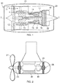
- a ducted fan gas turbine engine is generally indicated at 10 and has a principal and rotational axis X-X.
- the engine comprises, in axial flow series, an air intake 11, a propulsive fan 12, an intermediate pressure compressor 13, a high-pressure compressor 14, combustion equipment 15, a high-pressure turbine 16, an intermediate pressure turbine 17, a low-pressure turbine 18 and a core engine exhaust nozzle 19.
- a nacelle 21 generally surrounds the engine 10 and defines the intake 11, a bypass duct 22 and a bypass exhaust nozzle 23.
- air entering the intake 11 is accelerated by the fan 12 to produce two air flows: a first air flow A into the intermediate-pressure compressor 13 and a second airflow B which passes through the bypass duct 22 to provide propulsive thrust.
- the intermediate-pressure compressor 13 compresses the air flow A directed into it before delivering that air to the high-pressure compressor 14 where further compression takes place.
- the compressed air exhausted from the high-pressure compressor 14 is directed into the combustion equipment 15 where it is mixed with fuel and the mixture combusted.
- the resultant hot combustion products then expand through, and thereby drive the high, intermediate and low-pressure turbines 16, 17, 18 before being exhausted through the nozzle 19 to provide additional propulsive thrust.
- the high, intermediate and low-pressure turbines respectively drive the high and intermediate-pressure compressors 14, 13 and the fan 12 by suitable interconnecting shafts.
- gas turbine engines to which the present disclosure may be applied may have alternative configurations.
- such engines may have an alternative number of interconnecting shafts (e.g. two) and/or an alternative number of compressors and/or turbines.
- the engine may comprise a gearbox provided in the drive train from a turbine to a compressor and/or fan.
- the gas turbine engine has at least one synchronous electrical machine according to the present disclosure.
- the electrical machine includes a stator having a circumferential row of teeth carrying stator windings, and a coaxial rotor having a circumferential row of poles carrying field windings.
- the electrical machine may operate as a generator powered by one of the above-mentioned interconnecting shafts, or as a starter motor.
- the electrical machine may be used in other applications, such as a motor in a marine propulsion system.
- Figure 2 shows schematically an outboard marine propulsion unit having a synchronous motor including a stator 30 and a rotor 40.
- the unit also has a brushless exciter 24, a shaft 25 for the rotor mounted on bearings 26, and a propeller 27 which turns with the rotor.
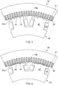
- FIG 3 shows the FE geometry on a transverse cross-section through a first synchronous motor (Motor 1) having a stator 30 with teeth 31 and stator windings 32, and a rotor 40 with poles 41 and field windings 42.
- Each pole has a pair of side flanks 43a, 43b and a tip surface 44 which extends continuously therebetween to form an air gap to the teeth of the stator.
- Recesses 45 in the tip surface correspond to the positions of damper bars in the motors discussed below in respect of Figures 4 and 5 .
- the thickness of the air gap of each pole increases smoothly and symmetrically towards both side flanks 43a, 43b, giving the motor similar performance characteristics in both rotation directions such that either one of the side flanks can be the leading edge or the trailing edge.
- Figure 4 shows the FE geometry on a transverse cross-section through a second synchronous motor (Motor 2) which is identical to Motor 1 except that the tip surface 44 now carries a row of permanent magnets 46 which extends across the tip surface from one of the side flanks 43a to the other side flank 43b.
- a row of damper bars 47 which are part of a damper winding (ammortisseur) of the motor, also extend across the tip surface.
- the damper winding which includes end plates at the opposing axial end faces of the rotor 40 to which the damper bars are connected, is used in a conventional manner to smooth and accelerate starting, and to compensate for transient effects and unbalanced conditions.
- the damper winding can also protect the permanent magnets 46 during a short circuit event.
- stator currents can rise rapidly at the beginning of a short circuit.
- high frequency currents will induce currents in the damper bars, and a flux-screen can thus be formed which helps to prevent the stator magnetic field from penetrating the magnets 46, forcing it through leakage paths in the vicinity of the air gap.
- the magnets 46 of each pole 41 are of uniform thickness across the entire tip surface 44, and the thickness of the air gap again increases smoothly and symmetrically towards both side flanks. Thus like Motor 1, Motor 2 has similar performance characteristics in both rotation directions.
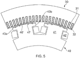
- Figure 5 shows the FE geometry on a transverse cross-section through a third synchronous motor (Motor 3) which is similar to Motor 2 except that the magnets 46' and the air gap are modified such that the rotor 40 now has a preferred rotation direction (anticlockwise as drawn in Figure 5 for motoring action).
- Motor 3 synchronous motor
- the magnets of each pole 41 now increase smoothly in radial thickness with progressive distance across the tip surface 44 from the leading edge side flank 43a to the trailing edge side flank 43b.
- the radial thickness of the air gap increases smoothly with progressive distance across the tip surface from the trailing side flank to the leading edge side flank.
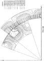
- Figure 6A shows a FE flux prediction for Motor 1
- Figure 6B shows a FE flux prediction for Motor 2
- Figure 6C shows a FE flux prediction for Motor 3, all at unity power factor when the cross-magnetizing effect on the air gap flux is at its strongest.
- the flux predictions show that the smoothly increasing magnet thickness of Motor 3 can compensate for armature reaction that otherwise produces a net loss of flux due to partial-magnetization of the leading edge of a pole and partial-demagnetization of the trailing edge.
- Figure 7A shows plots of FE-modelled air gap flux density waveforms for Motors 1 to 3 at no-load operation
- Figure 7B shows plots of FE-modelled air gap flux density waveforms for Motors 1 to 3 at full-load operation, all at unity power factor.
- Motor 1 has the most sinusoidal air gap flux waveform
- Motor 3 has the least sinusoidal air gap flux waveform due to its asymmetrical permanent magnet distribution on its rotor.
- the air gap flux waveforms are distorted due to the effect of armature reaction.
- the trailing edge (ringed in Figure 7B ) of Motor 3 has a higher flux density compared to Motors 1 and 2 due to the increased permanent magnet thickness at the trailing edge, and now Motor 3 has the most sinusoidal air gap flux waveform. Moreover, the gradual and smooth variation in magnet thickness allows the total pole flux waveform to be improved, and helps to smooth our distortions and prevent abrupt changes to the magnetic flux, particularly at the trailing edge.
- the armature reaction compensation provided by Motor 3 improves the line-line back electromotive force (EMF) harmonics at full load operation, as shown by Table 1 which provides the FE predicted back-EMF THDs of Motors 1 to 3 for the no-load and full-load operating conditions.
- Table 1 Motor 1 Motor 2 Motor 3 No-load back-EMF THD (%) 0.73912 0.95599 1.01244 Full-load back-EMF THD (%) 0.91306 0.82570 0.81209
- the magnets may be mounted inside armoured enclosures that can be made of high strength material such as nickel or titanium alloy. Such enclosures may employ modular designs which allows quick replacement of damaged magnets. They may also contain other elements, such as sensors and/or damper bars.
- Various fixing systems can be used to fix the magnets to the rotor, such as matching bolt holes in the magnets and rotor for installation of tie-rods, or dove tails or fir tree extensions to the magnets and correspondingly shaped recesses in the rotor.
- over-coating techniques such as cold spray coating, can be used to adhere the magnets to the rotor.
- the Motor 3 shown in Figure 5 can also be used as a generator, but in this case the preferred rotation direction is clockwise as drawn in Figure 5 .
Landscapes
- Engineering & Computer Science (AREA)
- Power Engineering (AREA)
- Permanent Magnet Type Synchronous Machine (AREA)
- Iron Core Of Rotating Electric Machines (AREA)
- Permanent Field Magnets Of Synchronous Machinery (AREA)
Abstract
Description
- The present disclosure relates to an electrical machine having means for compensating for armature magnetic reaction.
- Most synchronous motors are designed to operate at unity power factor. At unity power factor, the cross-magnetizing effect (armature magnetic reaction) on the air gap flux is at its strongest, with the leading edge of the pole being partly-magnetized and the trailing edge partly-demagnetized. Due to this effect, the machine incurs a net loss of flux.
- Similar problems can be encountered with synchronous generators.
- For electrical machines that rotate in a preferred direction, armature reaction mitigation schemes can be employed. One such scheme is to mount permanent magnets to tip surfaces of rotor poles as proposed in
US 2012/0248921 . However, this approach has a disadvantage in that if the magnets are not located at the correct positions and/or are too powerful, the line voltage total harmonic distortion (THD) will be worsened instead of being improved. - It would be desirable to provide more optimal armature reaction compensation.
- Accordingly, in a first aspect, the present disclosure provides a synchronous electrical machine including:
- a stator having a circumferential row of teeth carrying stator windings;
- a coaxial rotor having a circumferential row of poles carrying field windings;
- wherein each pole has first and second side flanks and a tip surface which extends continuously therebetween to form an air gap to the teeth of the stator, on a transverse cross-section through the machine, one of the side flanks forming a leading edge of the pole, and the other side flank forming an opposite, trailing edge of the pole;
- wherein each pole carries a row of permanent magnets which extends across the tip surface from one of the side flanks to the other side flank, the permanent magnets compensating for armature magnetic reaction; and
- wherein the radial thickness of the permanent magnets increases smoothly with progressive distance across the tip surface from one of the side flanks to the other side flank.
- By smoothly increasing the radial thickness of the permanent magnets in this way, armature reaction compensation can be provided which mitigates the level of distortion of the air gap flux waveform to create a more sinusoidal air gap flux on loaded operation, thereby reducing line voltage THD and increasing operational efficiency. However, the smooth increase in thickness makes the approach much less dependent on correct magnet location and power selection. These benefits are particularly apparent when the machine is operated at unity power factor.
- Advantageously, the rows of permanent magnets, or indeed the rotor as a whole, can be retrofitted into an existing machine, e.g. as an upgrade.
- In a second aspect, the present disclosure provides gas-turbine engine including the electrical machine according to the first aspect.
- In a third aspect, the present disclosure provides a marine propulsion unit including the electrical machine according to the first aspect. The marine propulsion unit can be an outboard drive unit.
- However, other unidirectional rotational motoring/generating applications are also possible. For example, the electrical machine may be used as a power plant generator, a micro-grid generator, or a hydro-power generator (e.g. as part of a water turbine).
- Optional features of the present disclosure will now be set out. These are applicable singly or in any combination with any aspect of the present disclosure.
- The permanent magnets may occupy at least 80% of the total area of the tip surface, and preferably occupy at least 90% or at least 95% of the total area of the tip surface. More preferably, the permanent magnets may extend substantially continuously across the tip surface from one of the side flanks to the other side flank, although 100% occupation of the total area of the tip surface by the permanent magnets may be difficult to achieve e.g. if some of the tip surface is needed to accommodate fixing means, damping means etc. for the permanent magnets.
- The radial thickness of the air gap may decrease smoothly with progressive distance across the tip surface from said one of the side flanks to said other side flank. This variation in air gap thickness can also help to compensate for armature magnetic reaction, although generally it is a weaker form of compensation than that provided by the permanent magnets.
- For example, the electrical machine may be configured as a synchronous motor in which the stator and field windings are both energised to produce respective magnetic fields which interact to drive rotation of the rotor. In this case, the radially thinnest part of the permanent magnets is typically at the side flank forming the leading edge and the radially thickest part of the permanent magnets is typically at the side flank forming the trailing edge. Moreover, if the motor has a variable air gap, the radially thickest part of the air gap is typically at the side flank forming the leading edge and the radially thinnest part of the air gap is typically at the side flank forming the trailing edge.
- As another example, the electrical machine may be configured as a synchronous generator in which rotation of the rotor combined with a magnetic field produced by synchronised energisation of the field windings induces a voltage in the stator. In this case, the radially thickest part of the permanent magnets is typically at the side flank forming the leading edge and the radially thinnest part of the permanent magnets is typically at the side flank forming the trailing edge. Moreover, if the motor has a variable air gap, the radially thinnest part of the air gap is typically at the side flank forming the leading edge and the radially thickest part of the air gap is typically at the side flank forming the trailing edge.
- These two examples are not mutually exclusive, i.e. the electrical machine can operate at some times as a motor and at other times as a generator. However, for a given application (i.e. motor or generator), having the radial thickness of the permanent magnets increase from one of the side flanks to the other side flank has an effect of giving the machine a preferred direction of rotation for that application.
- The electrical machine may further have a damper winding carried by the rotor. In case of a short-circuit in the stator windings, the damper winding can help to prevent an uncontrolled magnetic field produced by the stator windings from penetrating the permanent magnets.
- Embodiments of the present disclosure will now be described by way of example with reference to the accompanying drawings in which:
-
Figure 1 shows a longitudinal cross-section through a ducted fan gas turbine engine; -
Figure 2 shows schematically an outboard marine propulsion unit; -
Figure 3 shows a finite element (FE) geometry on a transverse cross-section through a first synchronous motor (Motor 1); -
Figure 4 shows the FE geometry on a transverse cross-section through a second synchronous motor (Motor 2); -
Figure 5 shows the FE geometry on a transverse cross-section through a third synchronous motor (Motor 3); -
Figure 6A shows a FE flux prediction forMotor 1,Figure 6B shows a FE flux prediction forMotor 2, andFigure 6C shows a FE flux prediction forMotor 3; and -
Figure 7A shows plots of FE-modelled air gap flux density waveforms forMotors 1 to 3 at no-load operation, andFigure 7B shows plots of FE-modelled air gap flux density waveforms for Motors 1 to 3 at full-load operation. - With reference to
Figure 1 , a ducted fan gas turbine engine is generally indicated at 10 and has a principal and rotational axis X-X. The engine comprises, in axial flow series, anair intake 11, apropulsive fan 12, anintermediate pressure compressor 13, a high-pressure compressor 14,combustion equipment 15, a high-pressure turbine 16, anintermediate pressure turbine 17, a low-pressure turbine 18 and a coreengine exhaust nozzle 19. Anacelle 21 generally surrounds theengine 10 and defines theintake 11, abypass duct 22 and abypass exhaust nozzle 23. - During operation, air entering the
intake 11 is accelerated by thefan 12 to produce two air flows: a first air flow A into the intermediate-pressure compressor 13 and a second airflow B which passes through thebypass duct 22 to provide propulsive thrust. The intermediate-pressure compressor 13 compresses the air flow A directed into it before delivering that air to the high-pressure compressor 14 where further compression takes place. - The compressed air exhausted from the high-
pressure compressor 14 is directed into thecombustion equipment 15 where it is mixed with fuel and the mixture combusted. The resultant hot combustion products then expand through, and thereby drive the high, intermediate and low-pressure turbines nozzle 19 to provide additional propulsive thrust. The high, intermediate and low-pressure turbines respectively drive the high and intermediate-pressure compressors fan 12 by suitable interconnecting shafts. - Other gas turbine engines to which the present disclosure may be applied may have alternative configurations. By way of example such engines may have an alternative number of interconnecting shafts (e.g. two) and/or an alternative number of compressors and/or turbines. Further the engine may comprise a gearbox provided in the drive train from a turbine to a compressor and/or fan.
- The gas turbine engine has at least one synchronous electrical machine according to the present disclosure. The electrical machine includes a stator having a circumferential row of teeth carrying stator windings, and a coaxial rotor having a circumferential row of poles carrying field windings. The electrical machine may operate as a generator powered by one of the above-mentioned interconnecting shafts, or as a starter motor. However, the electrical machine may be used in other applications, such as a motor in a marine propulsion system. For example,
Figure 2 shows schematically an outboard marine propulsion unit having a synchronous motor including astator 30 and arotor 40. The unit also has abrushless exciter 24, ashaft 25 for the rotor mounted onbearings 26, and apropeller 27 which turns with the rotor. - Finite element (FE) analyses were performed to demonstrate the improvement in armature magnetic reaction compensation that can be achieved by the electrical machine.
- Thus
Figure 3 shows the FE geometry on a transverse cross-section through a first synchronous motor (Motor 1) having astator 30 withteeth 31 andstator windings 32, and arotor 40 withpoles 41 andfield windings 42. Each pole has a pair ofside flanks tip surface 44 which extends continuously therebetween to form an air gap to the teeth of the stator.Recesses 45 in the tip surface correspond to the positions of damper bars in the motors discussed below in respect ofFigures 4 and5 . The thickness of the air gap of each pole increases smoothly and symmetrically towards bothside flanks -
Figure 4 then shows the FE geometry on a transverse cross-section through a second synchronous motor (Motor 2) which is identical toMotor 1 except that thetip surface 44 now carries a row ofpermanent magnets 46 which extends across the tip surface from one of the side flanks 43a to theother side flank 43b. A row of damper bars 47, which are part of a damper winding (ammortisseur) of the motor, also extend across the tip surface. The damper winding, which includes end plates at the opposing axial end faces of therotor 40 to which the damper bars are connected, is used in a conventional manner to smooth and accelerate starting, and to compensate for transient effects and unbalanced conditions. However, the damper winding can also protect thepermanent magnets 46 during a short circuit event. In particular, stator currents can rise rapidly at the beginning of a short circuit. However, high frequency currents will induce currents in the damper bars, and a flux-screen can thus be formed which helps to prevent the stator magnetic field from penetrating themagnets 46, forcing it through leakage paths in the vicinity of the air gap. - The
magnets 46 of eachpole 41 are of uniform thickness across theentire tip surface 44, and the thickness of the air gap again increases smoothly and symmetrically towards both side flanks. Thus likeMotor 1,Motor 2 has similar performance characteristics in both rotation directions. - Finally,
Figure 5 shows the FE geometry on a transverse cross-section through a third synchronous motor (Motor 3) which is similar toMotor 2 except that the magnets 46' and the air gap are modified such that therotor 40 now has a preferred rotation direction (anticlockwise as drawn inFigure 5 for motoring action). This allows improvements in armature magnetic reaction compensation to be obtained. In particular, the magnets of eachpole 41 now increase smoothly in radial thickness with progressive distance across thetip surface 44 from the leadingedge side flank 43a to the trailingedge side flank 43b. In addition, the radial thickness of the air gap increases smoothly with progressive distance across the tip surface from the trailing side flank to the leading edge side flank. -
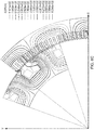
Figure 6A shows a FE flux prediction forMotor 1,Figure 6B shows a FE flux prediction forMotor 2, andFigure 6C shows a FE flux prediction forMotor 3, all at unity power factor when the cross-magnetizing effect on the air gap flux is at its strongest. The flux predictions show that the smoothly increasing magnet thickness ofMotor 3 can compensate for armature reaction that otherwise produces a net loss of flux due to partial-magnetization of the leading edge of a pole and partial-demagnetization of the trailing edge. - The compensation is illustrated by
Figure 7A , which shows plots of FE-modelled air gap flux density waveforms forMotors 1 to 3 at no-load operation, andFigure 7B which shows plots of FE-modelled air gap flux density waveforms forMotors 1 to 3 at full-load operation, all at unity power factor. At no-load (Figure 7A )Motor 1 has the most sinusoidal air gap flux waveform, whereasMotor 3 has the least sinusoidal air gap flux waveform due to its asymmetrical permanent magnet distribution on its rotor. However, at full-load the air gap flux waveforms are distorted due to the effect of armature reaction. The trailing edge (ringed inFigure 7B ) ofMotor 3 has a higher flux density compared toMotors - In addition, the armature reaction compensation provided by
Motor 3 improves the line-line back electromotive force (EMF) harmonics at full load operation, as shown by Table 1 which provides the FE predicted back-EMF THDs ofMotors 1 to 3 for the no-load and full-load operating conditions.Table 1 Motor 1Motor 2Motor 3No-load back-EMF THD (%) 0.73912 0.95599 1.01244 Full-load back-EMF THD (%) 0.91306 0.82570 0.81209 - To prevent damage to the permanent magnets due to centrifugal stress and physical impact, the magnets may be mounted inside armoured enclosures that can be made of high strength material such as nickel or titanium alloy. Such enclosures may employ modular designs which allows quick replacement of damaged magnets. They may also contain other elements, such as sensors and/or damper bars. Various fixing systems can be used to fix the magnets to the rotor, such as matching bolt holes in the magnets and rotor for installation of tie-rods, or dove tails or fir tree extensions to the magnets and correspondingly shaped recesses in the rotor. Additionally or alternatively, over-coating techniques, such as cold spray coating, can be used to adhere the magnets to the rotor.
- Although described above in respect of a motoring action, the
Motor 3 shown inFigure 5 can also be used as a generator, but in this case the preferred rotation direction is clockwise as drawn inFigure 5 . - While the invention has been described in conjunction with the exemplary embodiments described above, many equivalent modifications and variations will be apparent to those skilled in the art when given this disclosure. Accordingly, the exemplary embodiments of the invention set forth above are considered to be illustrative and not limiting. Various changes to the described embodiments may be made without departing from the scope of the invention.
Claims (8)
- A synchronous electrical machine including:a stator (30) having a circumferential row of teeth (31) carrying stator windings (32);a coaxial rotor (40) having a circumferential row of poles (41) carrying field windings (42);wherein each pole has first and second side flanks (43a, 43b) and a tip surface (44) which extends continuously therebetween to form an air gap to the teeth of the stator, on a transverse cross-section through the machine, one of the side flanks forming a leading edge of the pole, and the other side flank forming an opposite, trailing edge of the pole;wherein each pole carries a row of permanent magnets (46') which extends across the tip surface from one of the side flanks to the other side flank, the permanent magnets compensating for armature magnetic reaction; andwherein the radial thickness of the permanent magnets increases smoothly with progressive distance across the tip surface from one of the side flanks to the other side flank.
- An electrical machine according to claim 1, wherein the permanent magnets occupy at least 80% of the total area of the tip surface.
- An electrical machine according to claim 1 or 2, wherein the radial thickness of the air gap decreases smoothly with progressive distance across the tip surface from said one of the side flanks to said other side flank.
- An electrical machine according to any one of the previous claims which is configured as a synchronous motor in which the stator and field windings are both energised to produce respective magnetic fields which interact to drive rotation of the rotor;
wherein the radially thinnest part of the permanent magnets is at the side flank forming the leading edge and the radially thickest part of the permanent magnets is at the side flank forming the trailing edge. - An electrical machine according to any one of the previous claims which is configured as a synchronous generator in which rotation of the rotor combined with a magnetic field produced by synchronised energisation of the field windings induces a voltage in the stator windings;
wherein the radially thickest part of the permanent magnets is at the side flank forming the leading edge and the radially thinnest part of the permanent magnets is at the side flank forming the trailing edge. - An electrical machine according to any one of the previous claims further having a damper winding carried by the rotor.
- A gas-turbine engine (10) including the electrical machine according to any one of the previous claims.
- A marine propulsion unit including the electrical machine according to any one of claims 1 to 6.
Applications Claiming Priority (1)
| Application Number | Priority Date | Filing Date | Title |
|---|---|---|---|
| GBGB1719429.1A GB201719429D0 (en) | 2017-11-23 | 2017-11-23 | Electrical machine |
Publications (2)
| Publication Number | Publication Date |
|---|---|
| EP3490108A1 true EP3490108A1 (en) | 2019-05-29 |
| EP3490108B1 EP3490108B1 (en) | 2020-01-01 |
Family
ID=60950526
Family Applications (1)
| Application Number | Title | Priority Date | Filing Date |
|---|---|---|---|
| EP18204315.8A Active EP3490108B1 (en) | 2017-11-23 | 2018-11-05 | Electrical machine |
Country Status (3)
| Country | Link |
|---|---|
| US (1) | US10770958B2 (en) |
| EP (1) | EP3490108B1 (en) |
| GB (1) | GB201719429D0 (en) |
Citations (5)
| Publication number | Priority date | Publication date | Assignee | Title |
|---|---|---|---|---|
| US4573003A (en) * | 1983-09-30 | 1986-02-25 | Wisconsin Alumni Research Foundation | AC Machine optimized for converter operation |
| JPS61116954A (en) * | 1984-11-09 | 1986-06-04 | Sawafuji Electric Co Ltd | Generator |
| CN101719707A (en) * | 2010-01-14 | 2010-06-02 | 刘志新 | Hybrid excitation synchronous generator with low cogging effect |
| US20120248921A1 (en) * | 2009-04-29 | 2012-10-04 | Jean-Claude Mipo | Rotary electric machine with armature magnetic reaction compensation |
| CN205212670U (en) * | 2015-12-22 | 2016-05-04 | 珠海格力节能环保制冷技术研究中心有限公司 | Table pastes formula inner rotor PMSM |
Family Cites Families (1)
| Publication number | Priority date | Publication date | Assignee | Title |
|---|---|---|---|---|
| JPS63242157A (en) | 1987-03-27 | 1988-10-07 | Shinko Electric Co Ltd | Permanent magnet rotor for synchronous motor |
-
2017
- 2017-11-23 GB GBGB1719429.1A patent/GB201719429D0/en not_active Ceased
-
2018
- 2018-10-24 US US16/169,117 patent/US10770958B2/en active Active
- 2018-11-05 EP EP18204315.8A patent/EP3490108B1/en active Active
Patent Citations (5)
| Publication number | Priority date | Publication date | Assignee | Title |
|---|---|---|---|---|
| US4573003A (en) * | 1983-09-30 | 1986-02-25 | Wisconsin Alumni Research Foundation | AC Machine optimized for converter operation |
| JPS61116954A (en) * | 1984-11-09 | 1986-06-04 | Sawafuji Electric Co Ltd | Generator |
| US20120248921A1 (en) * | 2009-04-29 | 2012-10-04 | Jean-Claude Mipo | Rotary electric machine with armature magnetic reaction compensation |
| CN101719707A (en) * | 2010-01-14 | 2010-06-02 | 刘志新 | Hybrid excitation synchronous generator with low cogging effect |
| CN205212670U (en) * | 2015-12-22 | 2016-05-04 | 珠海格力节能环保制冷技术研究中心有限公司 | Table pastes formula inner rotor PMSM |
Also Published As
| Publication number | Publication date |
|---|---|
| GB201719429D0 (en) | 2018-01-10 |
| EP3490108B1 (en) | 2020-01-01 |
| US10770958B2 (en) | 2020-09-08 |
| US20190157956A1 (en) | 2019-05-23 |
Similar Documents
| Publication | Publication Date | Title |
|---|---|---|
| US11387724B2 (en) | Dual-rotor electric machine | |
| EP3680488B1 (en) | Electric machine having permanent magnets embedded in blades | |
| US8745990B2 (en) | Gas turbine engine with integrated electric starter/generator | |
| US9190892B2 (en) | Electro-magnetic coupling system | |
| US7750521B2 (en) | Double-sided starter/generator for aircrafts | |
| US11362550B2 (en) | Electrical machine with hybrid tooth design | |
| US7619332B2 (en) | Permanent magnet type electric rotating machine and wind turbine electric power generation system | |
| US9293952B2 (en) | Wound field flux switching machine with sinusoidal back electromotive force | |
| US9438091B2 (en) | Permanent magnet machine with two stators | |
| EP3457545B1 (en) | Segmented electrical machine | |
| US20190097479A1 (en) | Permanent magnet electrical machine | |
| US11777370B2 (en) | Turbogenerator for hybrid electric aeronautical propulsion | |
| EP3490108B1 (en) | Electrical machine | |
| CN114765392A (en) | Electric machine with a receiving belt | |
| CN108288879B (en) | Stator support for an electric machine | |
| EP3648306A1 (en) | Electrical machine having a segmented stator or rotor | |
| US20230361636A1 (en) | Electric machine having asymmetric magnet arrangement | |
| GB2626771A (en) | Electric machine assembly | |
| Cavagnino et al. | Eddy current losses reduction in fractional slot concentrated winding PM generators for more electric engine application | |
| Xu et al. | Research on high-speed permanent magnet generator for a miniature turbojet |
Legal Events
| Date | Code | Title | Description |
|---|---|---|---|
| PUAI | Public reference made under article 153(3) epc to a published international application that has entered the european phase |
Free format text: ORIGINAL CODE: 0009012 |
|
| STAA | Information on the status of an ep patent application or granted ep patent |
Free format text: STATUS: THE APPLICATION HAS BEEN PUBLISHED |
|
| AK | Designated contracting states |
Kind code of ref document: A1 Designated state(s): AL AT BE BG CH CY CZ DE DK EE ES FI FR GB GR HR HU IE IS IT LI LT LU LV MC MK MT NL NO PL PT RO RS SE SI SK SM TR |
|
| AX | Request for extension of the european patent |
Extension state: BA ME |
|
| STAA | Information on the status of an ep patent application or granted ep patent |
Free format text: STATUS: REQUEST FOR EXAMINATION WAS MADE |
|
| 17P | Request for examination filed |
Effective date: 20190903 |
|
| RBV | Designated contracting states (corrected) |
Designated state(s): AL AT BE BG CH CY CZ DE DK EE ES FI FR GB GR HR HU IE IS IT LI LT LU LV MC MK MT NL NO PL PT RO RS SE SI SK SM TR |
|
| GRAP | Despatch of communication of intention to grant a patent |
Free format text: ORIGINAL CODE: EPIDOSNIGR1 |
|
| STAA | Information on the status of an ep patent application or granted ep patent |
Free format text: STATUS: GRANT OF PATENT IS INTENDED |
|
| GRAS | Grant fee paid |
Free format text: ORIGINAL CODE: EPIDOSNIGR3 |
|
| GRAA | (expected) grant |
Free format text: ORIGINAL CODE: 0009210 |
|
| STAA | Information on the status of an ep patent application or granted ep patent |
Free format text: STATUS: THE PATENT HAS BEEN GRANTED |
|
| INTG | Intention to grant announced |
Effective date: 20191111 |
|
| AK | Designated contracting states |
Kind code of ref document: B1 Designated state(s): AL AT BE BG CH CY CZ DE DK EE ES FI FR GB GR HR HU IE IS IT LI LT LU LV MC MK MT NL NO PL PT RO RS SE SI SK SM TR |
|
| REG | Reference to a national code |
Ref country code: GB Ref legal event code: FG4D |
|
| REG | Reference to a national code |
Ref country code: CH Ref legal event code: EP Ref country code: AT Ref legal event code: REF Ref document number: 1221022 Country of ref document: AT Kind code of ref document: T Effective date: 20200115 |
|
| REG | Reference to a national code |
Ref country code: IE Ref legal event code: FG4D |
|
| REG | Reference to a national code |
Ref country code: DE Ref legal event code: R096 Ref document number: 602018001896 Country of ref document: DE |
|
| RAP2 | Party data changed (patent owner data changed or rights of a patent transferred) |
Owner name: ROLLS-ROYCE PLC |
|
| REG | Reference to a national code |
Ref country code: NL Ref legal event code: MP Effective date: 20200101 |
|
| REG | Reference to a national code |
Ref country code: LT Ref legal event code: MG4D |
|
| PG25 | Lapsed in a contracting state [announced via postgrant information from national office to epo] |
Ref country code: LT Free format text: LAPSE BECAUSE OF FAILURE TO SUBMIT A TRANSLATION OF THE DESCRIPTION OR TO PAY THE FEE WITHIN THE PRESCRIBED TIME-LIMIT Effective date: 20200101 Ref country code: RS Free format text: LAPSE BECAUSE OF FAILURE TO SUBMIT A TRANSLATION OF THE DESCRIPTION OR TO PAY THE FEE WITHIN THE PRESCRIBED TIME-LIMIT Effective date: 20200101 Ref country code: NO Free format text: LAPSE BECAUSE OF FAILURE TO SUBMIT A TRANSLATION OF THE DESCRIPTION OR TO PAY THE FEE WITHIN THE PRESCRIBED TIME-LIMIT Effective date: 20200401 Ref country code: NL Free format text: LAPSE BECAUSE OF FAILURE TO SUBMIT A TRANSLATION OF THE DESCRIPTION OR TO PAY THE FEE WITHIN THE PRESCRIBED TIME-LIMIT Effective date: 20200101 Ref country code: CZ Free format text: LAPSE BECAUSE OF FAILURE TO SUBMIT A TRANSLATION OF THE DESCRIPTION OR TO PAY THE FEE WITHIN THE PRESCRIBED TIME-LIMIT Effective date: 20200101 Ref country code: PT Free format text: LAPSE BECAUSE OF FAILURE TO SUBMIT A TRANSLATION OF THE DESCRIPTION OR TO PAY THE FEE WITHIN THE PRESCRIBED TIME-LIMIT Effective date: 20200527 Ref country code: FI Free format text: LAPSE BECAUSE OF FAILURE TO SUBMIT A TRANSLATION OF THE DESCRIPTION OR TO PAY THE FEE WITHIN THE PRESCRIBED TIME-LIMIT Effective date: 20200101 |
|
| PG25 | Lapsed in a contracting state [announced via postgrant information from national office to epo] |
Ref country code: SE Free format text: LAPSE BECAUSE OF FAILURE TO SUBMIT A TRANSLATION OF THE DESCRIPTION OR TO PAY THE FEE WITHIN THE PRESCRIBED TIME-LIMIT Effective date: 20200101 Ref country code: IS Free format text: LAPSE BECAUSE OF FAILURE TO SUBMIT A TRANSLATION OF THE DESCRIPTION OR TO PAY THE FEE WITHIN THE PRESCRIBED TIME-LIMIT Effective date: 20200501 Ref country code: LV Free format text: LAPSE BECAUSE OF FAILURE TO SUBMIT A TRANSLATION OF THE DESCRIPTION OR TO PAY THE FEE WITHIN THE PRESCRIBED TIME-LIMIT Effective date: 20200101 Ref country code: BG Free format text: LAPSE BECAUSE OF FAILURE TO SUBMIT A TRANSLATION OF THE DESCRIPTION OR TO PAY THE FEE WITHIN THE PRESCRIBED TIME-LIMIT Effective date: 20200401 Ref country code: HR Free format text: LAPSE BECAUSE OF FAILURE TO SUBMIT A TRANSLATION OF THE DESCRIPTION OR TO PAY THE FEE WITHIN THE PRESCRIBED TIME-LIMIT Effective date: 20200101 Ref country code: GR Free format text: LAPSE BECAUSE OF FAILURE TO SUBMIT A TRANSLATION OF THE DESCRIPTION OR TO PAY THE FEE WITHIN THE PRESCRIBED TIME-LIMIT Effective date: 20200402 |
|
| REG | Reference to a national code |
Ref country code: DE Ref legal event code: R097 Ref document number: 602018001896 Country of ref document: DE |
|
| PG25 | Lapsed in a contracting state [announced via postgrant information from national office to epo] |
Ref country code: EE Free format text: LAPSE BECAUSE OF FAILURE TO SUBMIT A TRANSLATION OF THE DESCRIPTION OR TO PAY THE FEE WITHIN THE PRESCRIBED TIME-LIMIT Effective date: 20200101 Ref country code: SM Free format text: LAPSE BECAUSE OF FAILURE TO SUBMIT A TRANSLATION OF THE DESCRIPTION OR TO PAY THE FEE WITHIN THE PRESCRIBED TIME-LIMIT Effective date: 20200101 Ref country code: DK Free format text: LAPSE BECAUSE OF FAILURE TO SUBMIT A TRANSLATION OF THE DESCRIPTION OR TO PAY THE FEE WITHIN THE PRESCRIBED TIME-LIMIT Effective date: 20200101 Ref country code: RO Free format text: LAPSE BECAUSE OF FAILURE TO SUBMIT A TRANSLATION OF THE DESCRIPTION OR TO PAY THE FEE WITHIN THE PRESCRIBED TIME-LIMIT Effective date: 20200101 Ref country code: SK Free format text: LAPSE BECAUSE OF FAILURE TO SUBMIT A TRANSLATION OF THE DESCRIPTION OR TO PAY THE FEE WITHIN THE PRESCRIBED TIME-LIMIT Effective date: 20200101 Ref country code: ES Free format text: LAPSE BECAUSE OF FAILURE TO SUBMIT A TRANSLATION OF THE DESCRIPTION OR TO PAY THE FEE WITHIN THE PRESCRIBED TIME-LIMIT Effective date: 20200101 |
|
| PLBE | No opposition filed within time limit |
Free format text: ORIGINAL CODE: 0009261 |
|
| STAA | Information on the status of an ep patent application or granted ep patent |
Free format text: STATUS: NO OPPOSITION FILED WITHIN TIME LIMIT |
|
| REG | Reference to a national code |
Ref country code: AT Ref legal event code: MK05 Ref document number: 1221022 Country of ref document: AT Kind code of ref document: T Effective date: 20200101 |
|
| 26N | No opposition filed |
Effective date: 20201002 |
|
| PG25 | Lapsed in a contracting state [announced via postgrant information from national office to epo] |
Ref country code: IT Free format text: LAPSE BECAUSE OF FAILURE TO SUBMIT A TRANSLATION OF THE DESCRIPTION OR TO PAY THE FEE WITHIN THE PRESCRIBED TIME-LIMIT Effective date: 20200101 Ref country code: AT Free format text: LAPSE BECAUSE OF FAILURE TO SUBMIT A TRANSLATION OF THE DESCRIPTION OR TO PAY THE FEE WITHIN THE PRESCRIBED TIME-LIMIT Effective date: 20200101 |
|
| PG25 | Lapsed in a contracting state [announced via postgrant information from national office to epo] |
Ref country code: PL Free format text: LAPSE BECAUSE OF FAILURE TO SUBMIT A TRANSLATION OF THE DESCRIPTION OR TO PAY THE FEE WITHIN THE PRESCRIBED TIME-LIMIT Effective date: 20200101 |
|
| PG25 | Lapsed in a contracting state [announced via postgrant information from national office to epo] |
Ref country code: MC Free format text: LAPSE BECAUSE OF FAILURE TO SUBMIT A TRANSLATION OF THE DESCRIPTION OR TO PAY THE FEE WITHIN THE PRESCRIBED TIME-LIMIT Effective date: 20200101 |
|
| PG25 | Lapsed in a contracting state [announced via postgrant information from national office to epo] |
Ref country code: LU Free format text: LAPSE BECAUSE OF NON-PAYMENT OF DUE FEES Effective date: 20201105 |
|
| REG | Reference to a national code |
Ref country code: BE Ref legal event code: MM Effective date: 20201130 |
|
| PG25 | Lapsed in a contracting state [announced via postgrant information from national office to epo] |
Ref country code: IE Free format text: LAPSE BECAUSE OF NON-PAYMENT OF DUE FEES Effective date: 20201105 |
|
| PG25 | Lapsed in a contracting state [announced via postgrant information from national office to epo] |
Ref country code: TR Free format text: LAPSE BECAUSE OF FAILURE TO SUBMIT A TRANSLATION OF THE DESCRIPTION OR TO PAY THE FEE WITHIN THE PRESCRIBED TIME-LIMIT Effective date: 20200101 Ref country code: MT Free format text: LAPSE BECAUSE OF FAILURE TO SUBMIT A TRANSLATION OF THE DESCRIPTION OR TO PAY THE FEE WITHIN THE PRESCRIBED TIME-LIMIT Effective date: 20200101 Ref country code: CY Free format text: LAPSE BECAUSE OF FAILURE TO SUBMIT A TRANSLATION OF THE DESCRIPTION OR TO PAY THE FEE WITHIN THE PRESCRIBED TIME-LIMIT Effective date: 20200101 |
|
| PG25 | Lapsed in a contracting state [announced via postgrant information from national office to epo] |
Ref country code: MK Free format text: LAPSE BECAUSE OF FAILURE TO SUBMIT A TRANSLATION OF THE DESCRIPTION OR TO PAY THE FEE WITHIN THE PRESCRIBED TIME-LIMIT Effective date: 20200101 Ref country code: AL Free format text: LAPSE BECAUSE OF FAILURE TO SUBMIT A TRANSLATION OF THE DESCRIPTION OR TO PAY THE FEE WITHIN THE PRESCRIBED TIME-LIMIT Effective date: 20200101 |
|
| REG | Reference to a national code |
Ref country code: CH Ref legal event code: PL |
|
| PG25 | Lapsed in a contracting state [announced via postgrant information from national office to epo] |
Ref country code: BE Free format text: LAPSE BECAUSE OF NON-PAYMENT OF DUE FEES Effective date: 20201130 |
|
| P01 | Opt-out of the competence of the unified patent court (upc) registered |
Effective date: 20230528 |
|
| PG25 | Lapsed in a contracting state [announced via postgrant information from national office to epo] |
Ref country code: LI Free format text: LAPSE BECAUSE OF NON-PAYMENT OF DUE FEES Effective date: 20220701 Ref country code: CH Free format text: LAPSE BECAUSE OF NON-PAYMENT OF DUE FEES Effective date: 20220701 |
|
| PG25 | Lapsed in a contracting state [announced via postgrant information from national office to epo] |
Ref country code: SI Free format text: LAPSE BECAUSE OF FAILURE TO SUBMIT A TRANSLATION OF THE DESCRIPTION OR TO PAY THE FEE WITHIN THE PRESCRIBED TIME-LIMIT Effective date: 20200101 |
|
| PGFP | Annual fee paid to national office [announced via postgrant information from national office to epo] |
Ref country code: DE Payment date: 20251126 Year of fee payment: 8 |
|
| PGFP | Annual fee paid to national office [announced via postgrant information from national office to epo] |
Ref country code: GB Payment date: 20251125 Year of fee payment: 8 |
|
| PGFP | Annual fee paid to national office [announced via postgrant information from national office to epo] |
Ref country code: FR Payment date: 20251124 Year of fee payment: 8 |