EP3490047B1 - Flow battery - Google Patents
Flow battery Download PDFInfo
- Publication number
- EP3490047B1 EP3490047B1 EP17830769.0A EP17830769A EP3490047B1 EP 3490047 B1 EP3490047 B1 EP 3490047B1 EP 17830769 A EP17830769 A EP 17830769A EP 3490047 B1 EP3490047 B1 EP 3490047B1
- Authority
- EP
- European Patent Office
- Prior art keywords
- electrode
- active material
- mediator
- liquid
- flow battery
- Prior art date
- Legal status (The legal status is an assumption and is not a legal conclusion. Google has not performed a legal analysis and makes no representation as to the accuracy of the status listed.)
- Active
Links
Images






Classifications
-
- H—ELECTRICITY
- H01—ELECTRIC ELEMENTS
- H01M—PROCESSES OR MEANS, e.g. BATTERIES, FOR THE DIRECT CONVERSION OF CHEMICAL ENERGY INTO ELECTRICAL ENERGY
- H01M8/00—Fuel cells; Manufacture thereof
- H01M8/18—Regenerative fuel cells, e.g. redox flow batteries or secondary fuel cells
- H01M8/184—Regeneration by electrochemical means
- H01M8/188—Regeneration by electrochemical means by recharging of redox couples containing fluids; Redox flow type batteries
-
- H—ELECTRICITY
- H01—ELECTRIC ELEMENTS
- H01M—PROCESSES OR MEANS, e.g. BATTERIES, FOR THE DIRECT CONVERSION OF CHEMICAL ENERGY INTO ELECTRICAL ENERGY
- H01M4/00—Electrodes
- H01M4/02—Electrodes composed of, or comprising, active material
- H01M4/36—Selection of substances as active materials, active masses, active liquids
- H01M4/38—Selection of substances as active materials, active masses, active liquids of elements or alloys
- H01M4/381—Alkaline or alkaline earth metals elements
- H01M4/382—Lithium
-
- H—ELECTRICITY
- H01—ELECTRIC ELEMENTS
- H01M—PROCESSES OR MEANS, e.g. BATTERIES, FOR THE DIRECT CONVERSION OF CHEMICAL ENERGY INTO ELECTRICAL ENERGY
- H01M8/00—Fuel cells; Manufacture thereof
- H01M8/02—Details
- H01M8/0202—Collectors; Separators, e.g. bipolar separators; Interconnectors
- H01M8/023—Porous and characterised by the material
-
- H—ELECTRICITY
- H01—ELECTRIC ELEMENTS
- H01M—PROCESSES OR MEANS, e.g. BATTERIES, FOR THE DIRECT CONVERSION OF CHEMICAL ENERGY INTO ELECTRICAL ENERGY
- H01M8/00—Fuel cells; Manufacture thereof
- H01M8/04—Auxiliary arrangements, e.g. for control of pressure or for circulation of fluids
- H01M8/04082—Arrangements for control of reactant parameters, e.g. pressure or concentration
- H01M8/04186—Arrangements for control of reactant parameters, e.g. pressure or concentration of liquid-charged or electrolyte-charged reactants
-
- H—ELECTRICITY
- H01—ELECTRIC ELEMENTS
- H01M—PROCESSES OR MEANS, e.g. BATTERIES, FOR THE DIRECT CONVERSION OF CHEMICAL ENERGY INTO ELECTRICAL ENERGY
- H01M8/00—Fuel cells; Manufacture thereof
- H01M8/04—Auxiliary arrangements, e.g. for control of pressure or for circulation of fluids
- H01M8/04276—Arrangements for managing the electrolyte stream, e.g. heat exchange
- H01M8/04283—Supply means of electrolyte to or in matrix-fuel cells
-
- H—ELECTRICITY
- H01—ELECTRIC ELEMENTS
- H01M—PROCESSES OR MEANS, e.g. BATTERIES, FOR THE DIRECT CONVERSION OF CHEMICAL ENERGY INTO ELECTRICAL ENERGY
- H01M8/00—Fuel cells; Manufacture thereof
- H01M8/20—Indirect fuel cells, e.g. fuel cells with redox couple being irreversible
-
- H—ELECTRICITY
- H01—ELECTRIC ELEMENTS
- H01M—PROCESSES OR MEANS, e.g. BATTERIES, FOR THE DIRECT CONVERSION OF CHEMICAL ENERGY INTO ELECTRICAL ENERGY
- H01M8/00—Fuel cells; Manufacture thereof
- H01M8/22—Fuel cells in which the fuel is based on materials comprising carbon or oxygen or hydrogen and other elements; Fuel cells in which the fuel is based on materials comprising only elements other than carbon, oxygen or hydrogen
- H01M8/225—Fuel cells in which the fuel is based on materials comprising particulate active material in the form of a suspension, a dispersion, a fluidised bed or a paste
-
- H—ELECTRICITY
- H01—ELECTRIC ELEMENTS
- H01M—PROCESSES OR MEANS, e.g. BATTERIES, FOR THE DIRECT CONVERSION OF CHEMICAL ENERGY INTO ELECTRICAL ENERGY
- H01M2300/00—Electrolytes
- H01M2300/0017—Non-aqueous electrolytes
- H01M2300/0025—Organic electrolyte
-
- H—ELECTRICITY
- H01—ELECTRIC ELEMENTS
- H01M—PROCESSES OR MEANS, e.g. BATTERIES, FOR THE DIRECT CONVERSION OF CHEMICAL ENERGY INTO ELECTRICAL ENERGY
- H01M2300/00—Electrolytes
- H01M2300/0017—Non-aqueous electrolytes
- H01M2300/0065—Solid electrolytes
- H01M2300/0068—Solid electrolytes inorganic
- H01M2300/0071—Oxides
-
- Y—GENERAL TAGGING OF NEW TECHNOLOGICAL DEVELOPMENTS; GENERAL TAGGING OF CROSS-SECTIONAL TECHNOLOGIES SPANNING OVER SEVERAL SECTIONS OF THE IPC; TECHNICAL SUBJECTS COVERED BY FORMER USPC CROSS-REFERENCE ART COLLECTIONS [XRACs] AND DIGESTS
- Y02—TECHNOLOGIES OR APPLICATIONS FOR MITIGATION OR ADAPTATION AGAINST CLIMATE CHANGE
- Y02E—REDUCTION OF GREENHOUSE GAS [GHG] EMISSIONS, RELATED TO ENERGY GENERATION, TRANSMISSION OR DISTRIBUTION
- Y02E60/00—Enabling technologies; Technologies with a potential or indirect contribution to GHG emissions mitigation
- Y02E60/30—Hydrogen technology
- Y02E60/50—Fuel cells
Definitions
- the present disclosure relates to a flow battery.
- PTL 1 discloses a redox flow battery that uses a negative electrode slurry solution containing a non-aqueous solvent and metal particles serving as solid negative electrode active material particles.
- US 2015/0255803 A1 discloses polyarene mediators for a mediated redox flow battery.
- a mediated redox flow battery includes a series of secondary organic molecules that form highly reduced anionic radicals as reaction mediator pairs for the reduction and oxidation of primary high capacity redox species ex situ from the electrochemical cell stack. Arenes are reduced to stable anionic radicals that in turn reduce a primary anode to the charged state. The primary anode is then discharged using a second lower potential (more positive) arene. Compatible separators and solvents are also disclosed in US 2015/0255803 A1 .
- Redox flow devices are described in US 201110189520 A1 including a positive electrode current collector, a negative electrode current collector, and an ion-permeable membrane separating said positive and negative current collectors, positioned and arranged to define a positive electroactive zone and a negative electroactive zone; wherein at least one of said positive and negative electroactive zone comprises a flowable semi-solid composition comprising ion storage compound particles capable of taking up or releasing said ions during operation of the cell, and wherein the ion storage compound particles have a polydisperse size distribution in which the finest particles present in at least 5 vol % of the total volume, is at least a factor of 5 smaller than the largest particles present in at least 5 vol % of the total volume.
- a flow battery includes: a case; a separator for separating the inside of the case into a positive electrode chamber and a negative electrode chamber; a positive electrode collector arranged in the positive electrode chamber; and a negative electrode collector arranged in the negative electrode chamber.
- a positive electrode side circulation path is arranged between the positive electrode chamber and a positive electrode reservoir container, and a positive electrode side circulation pump is attached to the middle of the positive electrode side circulation path.
- a negative electrode side circulation path is arranged between the negative electrode chamber and the negative electrode reservoir container, and a negative electrode side circulation pump is attached to the middle of the negative electrode side circulation path.
- positive electrode mediator contained electrolyte is allowed to circulate by the negative electrode side circulation pump so as to be brought into contact with the positive electrode collector, and negative electrode mediator contained electrolyte is allowed to circulate by a negative electrode side circulation pump so as to be brought into contact with the negative electrode collector, and charge and discharge is performed.
- a flow battery according to the present invention is defined in claim 1. Preferred embodiments are defined in the dependent claims.
- the present disclosure can provide a high-energy density flow battery.
- Embodiments of the present disclosure will next be described with reference to the drawings.
- Embodiments 1 and 2 are not covered by the claims, but are provided for being useful for understanding the invention.
- Fig. 1 is a block diagram showing a general structure of a flow battery 1000 in embodiment 1.
- the flow battery 1000 in embodiment 1 includes a first liquid 110, a first electrode 210, and a first active material 310.
- the first liquid 110 contains dissolved therein a charge mediator 111 and a discharge mediator 112.
- the first electrode 210 is immersed in the first liquid 110.
- the first active material 310 is immersed in the first liquid 110.
- the equilibrium potential of the charge mediator 111 is lower than the equilibrium potential of the first active material 310.
- the equilibrium potential of the discharge mediator 112 is higher than the equilibrium potential of the first active material 310.
- the flow battery configured as above can have both a high energy density and a long cycle life.
- the active material is used, the active material itself is not circulated. Therefore, for example, a high-capacity powdery active material for charge and discharge reactions can be used as the first active material 310. This allows a high energy density and a high capacity to be achieved.
- the flow battery provided can have a long cycle life.
- the first active material 310 used is an active material having a relatively low equilibrium potential (vs. Li/Li + ) (e.g., graphite)
- a material having a relatively low equilibrium potential (vs. Li/Li + ) e.g., a condensed aromatic compound
- the flow battery negative electrode provided can have a lower potential. Therefore, the flow battery provided can have a high battery voltage (discharge voltage).
- lithium may be dissolved in the first liquid 110.
- the first active material 310 may be a material having the property of occluding and releasing lithium.
- the charge mediator 111 may be reduced on the first electrode 210. Then the charge mediator 111 reduced on the first electrode 210 may be oxidized by the first active material 310, and the first active material 310 may occlude lithium.
- the first active material 310 containing lithium occluded therein may reduce the discharge mediator 112 and may release the lithium, and the discharge mediator 112 reduced by the first active material 310 may be oxidized on the first electrode 210.
- the first active material 310 used may be, for example, an active material having the property of reversibly occluding and releasing lithium (e.g., lithium ions).
- the material design of the first active material 310 is facilitated.
- a higher capacity can be achieved.
- the discharge mediator 112 may be reduced on the first electrode 210 during charging.
- the charge mediator 111 may be oxidized on the first electrode 210.
- the discharge mediator 112 when the discharge mediator 112 is reduced on the first electrode 210 during charging, the amount of the discharge mediator 112 to be oxidized on the first electrode 210 during discharging can be increased.
- the charge mediator 111 is discharged on the first electrode 210 during discharging, the amount of the charge mediator 111 to be reduced on the first electrode 210 during charging can be increased. This allows the charge-discharge capacity to increase.
- the charge mediator 111 and the discharge mediator 112 are oxidized or reduced on the first electrode 210.
- the discharge mediator 112 undergoes a reduction reaction with the first active material 310, or the charge mediator 111 undergoes an oxidation reaction with the first active material 310.
- the charge mediator 111 and the discharge mediator 112 may be condensed aromatic compounds.
- the first liquid 110 containing these condensed aromatic compounds dissolved therein has the property of causing lithium to release solvated electrons and dissolve as cations.
- the charge mediator 111 and discharge mediator 112 provided can be electrochemically base.
- a solution e.g., an ether solution
- a condensed aromatic compound has the ability to dissolve lithium (e.g., lithium metal). Lithium easily releases electrons to form cations. Therefore, lithium donates electrons to the condensed aromatic compound in the solution and dissolves in the solution as cations.
- the condensed aromatic compound that has accepted the electrons solvates the electrons.
- the condensed aromatic compound solvating the electrons behaves as anions. Therefore, the condensed aromatic compound-containing solution itself has ion conductivity.
- Li cations and electrons are present in equivalent amounts. Therefore, the condensed aromatic compound-containing solution itself can have strong reducing properties (in other words, can be electrochemically base).
- the potential measured is considerably low.
- the potential observed depends on the degree of solvation of electrons by the condensed aromatic compound (i.e., the type of condensed aromatic compound).
- Examples of the condensed aromatic compound that exhibits a low potential include phenanthrene, biphenyl, O-terphenyl, triphenylene, anthracene, acenaphthene, acenaphthylene, fluoranthene, 1,10-phenanthroline, 2,2'-bipyridyl, benzophenone, trans-stilbene, 4,4'-bipyridyl, 3,3'-bipyridyl, 2,4'-bipyridyl, 2,3'-bipyridyl, cis-stilbene, acetophenone, propiophenone, butyrophenone, valerophenone, ethylenediamine, benzil, and tetraphenylcyclopentadienone.
- the charge mediator 111 may be at least one selected from the group consisting of phenanthrene, biphenyl, O-terphenyl, triphenylene, anthracene, acenaphthene, acenaphthylene, and fluoranthene.
- the charge mediator 111 provided can be electrochemically base. More specifically, the charge mediator provided can have a lower potential (vs. Li/Li + ) than a specific first active material 310 (e.g., graphite).
- a specific first active material 310 e.g., graphite
- the discharge mediator 112 may be at least one selected from the group consisting of 1,10-phenanthroline, 2,2'-bipyridyl, benzophenone, trans-stilbene, 4,4'-bipyridyl, 3,3'-bipyridyl, 2,4'-bipyridyl, 2,3'-bipyridyl, cis-stilbene, acetophenone, propiophenone, butyrophenone, valerophenone, ethylenediamine, benzil, and tetraphenylcyclopentadienone.
- the discharge mediator 112 provided can be electrochemically noble. More specifically, the discharge mediator 112 provided can have a higher potential (vs. Li/Li + ) than a specific first active material 310 (e.g., graphite).
- a specific first active material 310 e.g., graphite
- the discharge mediator 112 may be at least one selected from the group consisting of 2,2'-bipyridyl, trans-stilbene, 2,4'-bipyridyl, 2,3'-bipyridyl, cis-stilbene, propiophenone, butyrophenone, valerophenone, ethylenediamine, benzil, and tetraphenylcyclopentadienone.
- the discharge mediator 112 provided can be electrochemically noble. More specifically, the discharge mediator 112 provided cab have a higher potential (vs. Li/Li + ) than a specific first active material 310 (e.g., graphite). Moreover, the discharge mediator 112 can have a relatively low equilibrium potential (vs. Li/Li + ). In this case, the flow battery negative electrode provided can have a lower potential. Therefore, the flow battery provided can have a high battery voltage (discharge voltage).
- the first liquid 110 may be an ether solution.
- the first liquid 110 provided may be an electrolyte solution containing the charge mediator 111 and the discharge mediator 112.
- the solvent for the charge mediator 111 and the discharge mediator 112 is the ether solution with no electronic conductivity, the ether solution itself can have the properties of an electrolyte solution.
- the ether used may be tetrahydrofuran (THF), 2-methyltetrahydrofuran (2MeTHF), dimethoxyethane (DME), 1 ,3-dioxane (1,3DO), 4-methyl-1,3-dioxane (4Me1,3DO), etc.
- the first active material 310 may contain graphite.
- the first active material 310 can have a relatively low equilibrium potential (vs. Li/Li + ). Therefore, a material having a relatively low equilibrium potential (vs. Li/Li + ) (e.g., a condensed aromatic compound) can be used as the discharge mediator 112.
- the flow battery negative electrode provided can have a lower potential. Therefore, the flow battery provided can have a high battery voltage (discharge voltage).
- the composition of graphite containing lithium occluded therein (i.e., a graphite intercalation compound generated during discharging) and used as the first active material 310 may be at least one of C 24 Li, C 18 Li, C 12 Li, and C 6 Li.
- the first active material 310 used is graphite (C 6 Li)
- the graphite reacts with lithium and is fully reduced (i.e., the graphite occludes lithium to form C 6 Li), and the charging is completed.
- the potential of C 6 Li is about 0.15 V vs. Li/Li + . Therefore, a mediator-type negative electrode can be formed by using as the charge mediator a condensed aromatic compound having a lower potential than C 6 Li and using as the discharge mediator a condensed aromatic compound having a higher potential than C 6 Li.
- Figs. 2 , 8 , and 10 are tables showing the results of measurement of the potentials of condensed aromatic compounds usable as the charge mediator 111.
- Figs. 3 , 9, and 11 are tables showing the results of measurement of the potentials of condensed aromatic compounds usable as the discharge mediator 112.
- a 2 ⁇ 2 cm copper foil was wrapped with a polypropylene-made porous separator, and the entire separator was wrapped with a large amount of lithium metal foil.
- a tab was attached to each of the copper foil and the lithium metal.
- a laminate exterior package was attached to the above product.
- 2MeTHF containing dissolved therein a condensed aromatic compound at a molar concentration (M) shown in one of Figs. 2, 3 , 8 , 9, 10, and 11 was poured into the laminate exterior package, and the laminate exterior package was hermetically heat-sealed.
- a potential measurement cell was thereby prepared for each condensed aromatic compound.
- Figs. 2, 3 , 8 , 9, 10, and 11 show the potentials (V vs. Li/Li + ) measured with respect to lithium metal using these potential measurement cells.
- the ether used was 2MeTHF, but other ethers can also be used.
- Li metal was dissolved in a 2MeTHF solution containing dissolved therein a charge mediator at a concentration of 0.1M.
- Graphite was immersed in this solution for 4 days.
- a change in color indicating the change from graphite (black) to C 6 Li (gold) was observed.
- C 6 Li was immersed in a 2MeTHF solution containing dissolved therein a discharge mediator at a concentration of 0.1M for 4 days.
- a change in color indicating the change from C 6 Li (gold) to graphite (black) was observed.
- Figs. 2 and 3 show changes when C 6 Li and lithium metal were immersed in 2MeTHF containing a condensed aromatic compound dissolved therein.
- each charge mediator 111 has no ability to dissolve Li contained in C 6 Li.
- each discharge mediator 112 has the ability to dissolve Li contained in C 6 Li.
- the difference in ability can be explained by the difference between the potential of each lithium metal solution and the potential of C 6 Li. Specifically, a mediator having a higher potential than C 6 Li (about 0.15 V vs. Li/Li + ) has the ability to dissolve Li contained in C 6 Li. A mediator having a lower potential than C 6 Li (about 0.15 V vs. Li/Li + ) has no ability to dissolve Li contained in C 6 Li.
- a condensed aromatic compound having a potential lower than C 6 Li can be used as the charge mediator 111.
- a condensed aromatic compound having a potential higher than C 6 Li can be used as the discharge mediator 112.
- the charge mediator 111 used may be phenanthrene, triphenylene, or biphenyl.
- the discharge mediator 112 used may be trans-stilbene, butyrophenone, valerophenone, or ethylenediamine. This can further improve the charge-discharge energy efficiency.
- the ether used may be an ether that is not co-intercalated with Li ions into graphite.
- the ether is not co-intercalated into graphite, and a further increase in capacity density can be achieved.
- the first active material 310 used may be a powdery active material.
- the first active material 310 used may be a powdery active material.
- the first active material 310 used may be a pellet-like active material (prepared, for example, by forming a powder into pellets).
- the production can be simplified, and the production cost can be reduced.
- the first active material 310 used may be an active material pelleted using a commonly known binder (such as polyvinylidene fluoride, polypropylene, polyethylene, or polyimide).
- a commonly known binder such as polyvinylidene fluoride, polypropylene, polyethylene, or polyimide.
- the first active material 310 may be a material that does not dissolve (i.e., is insoluble) in the first liquid 110.
- the charge mediator 111 and the discharge mediator 112 are circulated together with the first liquid 110, but the first active material 310 is not circulated.
- the first electrode 210 may be a negative electrode, and a second electrode 220 may be a positive electrode.
- the first electrode 210 can serve as a positive electrode.
- the first electrode 210 may be a positive electrode
- the second electrode 220 may be a negative electrode.
- the first electrode 210 may have a surface serving as a reaction field for the charge mediator 111 and the discharge mediator 112.
- a material stable in the first liquid 110 may be used for the first electrode 210.
- the material used for the first electrode 210 may be stable during an electrode reaction, which is an electrochemical reaction.
- a metal such as stainless steel, iron, copper, or nickel
- carbon, etc. may be used for the first electrode 210.
- the first electrode 210 may have a structure with an increased surface area (e.g., a mesh, a nonwoven fabric, a surface roughened plate, or a sintered porous body). In this case, the first electrode 210 has a large specific surface area. This can facilitate the progress of the oxidation or reduction reaction of each of the charge mediator 111 and the discharge mediator 112.
- the second electrode 220 may have a structure including a current collector and an active material disposed on the current collector.
- a high-capacity active material can be used.
- a compound having the property of reversibly occluding and releasing lithium ions may be used as the active material for the second electrode 220.
- the second electrode 220 may be lithium metal.
- lithium metal is used for the second electrode 220, dissolution and precipitation of the metal serving as the positive electrode can be easily controlled, and a high capacity can be achieved.
- the flow battery 1000 in embodiment 1 may further include a separator 400.
- the separator 400 separates the first electrode 210 and the first liquid 110 from the second electrode 220.
- the separator 400 may be a microporous membrane (porous body) used for known secondary batteries.
- the separator 400 may be a porous membrane such as glass paper, which is a nonwoven fabric including glass fibers woven thereinto.
- the separator 400 may be a separation membrane having ion conductivity (lithium ion conductivity).
- the separator 400 may be an ion exchange resin membrane (such as a cation exchange membrane or an anion exchange membrane), a solid electrolyte membrane, etc.
- the flow battery 1000 in embodiment 1 may further include a first circulator 510.
- the first circulator 510 circulates the first liquid 110 between the first electrode 210 and the first active material 310.
- the charge mediator 111 and the discharge mediator 112 can be circulated together with the first liquid 110 between the first electrode 210 and the first active material 310. This allows the oxidation and reduction reactions of the materials to proceed more efficiently.
- the first circulator 510 may include, for example, a pipe, a tank, a pump, a valve, etc.
- One specific example of the first circulator 510 is a structure described later in embodiment 2.
- the first electrode 210 is a negative electrode and is made of stainless steel.
- the first liquid 110 is an ether solution containing dissolved therein the charge mediator 111 and the discharge mediator 112.
- the charge mediator 111 is one condensed aromatic compound (hereinafter denoted by ChMd).
- the discharge mediator 112 is one condensed aromatic compound (hereinafter denoted by DchMd).
- the first active material 310 is graphite (C 6 Li).
- the second electrode 220 is a positive electrode and includes a current collector (stainless steel) and lithium iron phosphate (LiFePO 4 ) used as an active material disposed on the current collector.
- a current collector stainless steel
- lithium iron phosphate LiFePO 4
- a voltage is applied between the first electrode 210 and the second electrode 220 to perform charging.
- the oxidation reaction of a positive electrode active material occurs when a voltage is applied. Specifically, lithium ions are released from the positive electrode active material. Electrons are thereby emitted from the second electrode 220 to the outside of the flow battery.
- Li + Li +
- the charge mediator 111 reduced on the first electrode 210 is transferred (supplied) through the first circulator 510 to a position in which the first active material 310 is disposed.
- the charge mediator 111 reduced on the first electrode 210 is oxidized by the first active material 310.
- the first active material 310 is reduced by the charge mediator 111.
- the first active material 310 thereby occludes lithium and forms C 6 Li.
- the charge mediator 111 oxidized by the first active material 310 is transferred (supplied) through the first circulator 510 to a position in which the first electrode 210 is disposed.
- the charge mediator 111 is unchanged in the overall reaction including circulation.
- the first active material 310 located in the position spaced apart from the first electrode 210 is brought to a charged state.
- the above charge reaction may proceed until one of a fully charged state of the first active material 310 and a fully charged state of the active material on the positive electrode side is reached.
- the first active material 310 and the positive electrode active material are in their charged states.
- Part of the lithium ions (Li + ) may be supplied from the first liquid 110 through the separator 400.
- the oxidation reactions of the charge mediator 111 and the discharge mediator 112 occur on the first electrode 210 serving as the negative electrode. Electrons are thereby emitted from the first electrode 210 to the outside of the flow battery.
- the discharge mediator 112 oxidized on the first electrode 210 is transferred (supplied) through the first circulator 510 to the position in which the first active material 310 is disposed.
- the discharge mediator 112 oxidized on the first electrode 210 is reduced by the first active material 310.
- the first active material 310 is oxidized by the discharge mediator 112.
- the first active material 310 thereby releases lithium.
- the discharge mediator 112 reduced by the first active material 310 is transferred (supplied) through the first circulator 510 to the position in which the first electrode 210 is disposed.
- the discharge mediator 112 is unchanged in the overall reaction including circulation.
- the first active material 310 located in the position spaced apart from the first electrode 210 is brought to a discharged state.
- the above discharge reaction may proceed until one of a fully discharged state of the first active material 310 and a fully discharged state of the active material on the positive electrode side is reached.
- Embodiment 2 will be described. However, the description will be omitted as appropriate when it overlaps with that of embodiment 1 above.
- Fig. 4 is a schematic diagram showing a general structure of a flow battery 2000 in embodiment 2.
- the flow battery 2000 in embodiment 2 includes, in addition to the structure of the flow battery 1000 in embodiment 1, the following structure.
- the first circulator 510 includes a first container 511.
- the first active material 310 and the first liquid 110 are contained in the first container 511.
- the first circulator 510 circulates the first liquid 110 between the first electrode 210 and the first container 511.
- the first active material 310 comes into contact with the first liquid 110. This causes at least one of the oxidation reaction of the charge mediator 111 by the first active material 310 and the reduction reaction of the discharge mediator 112 by the first active material 310 to proceed.
- the first liquid 110 and the first active material 310 can come into contact with each other in the first container 511.
- the area of contact between the first liquid 110 and the first active material 310 can be increased.
- the time of contact between the first liquid 110 and the first active material 310 can be increased. This allows the oxidation reaction of the charge mediator 111 by the first active material 310 and the reduction reaction of the discharge mediator 112 by the first active material 310 to proceed more efficiently.
- the first container 511 may be, for example, a tank.
- the first liquid 110 containing dissolved therein the charge mediator 111 and the discharge mediator 112 may be accommodated, for example, in spaces in the first active material 310 placed in the first container 511.
- the flow battery 2000 in embodiment 2 may further include an electrochemical reaction section 600, a positive electrode terminal 221, and a negative electrode terminal 211.
- the electrochemical reaction section 600 is separated by the separator 400 into a negative electrode chamber 610 and a positive electrode chamber 620.
- An electrode serving as the negative electrode (the first electrode 210 in the example shown in Fig. 4 ) is disposed in the negative electrode chamber 610.
- the negative electrode terminal 211 is connected to the electrode serving as the negative electrode.
- An electrode serving as the positive electrode (the second electrode 220 in the example shown in Fig. 4 ) is disposed in the positive electrode chamber 620.
- the positive electrode terminal 221 is connected to the electrode serving as the positive electrode.
- the negative electrode terminal 211 and the positive electrode terminal 221 are connected to, for example, a charge-discharge device.
- the charge-discharge device applies a voltage between the negative electrode terminal 211 and the positive electrode terminal 221 or collects electric power through the negative electrode terminal 211 and the positive electrode terminal 221.
- the first circulator 510 may include a pipe 514, a pipe 513, and a pump 515.
- One end of the pipe 514 is connected to the negative electrode chamber 610 or the positive electrode chamber 620, whichever includes the first electrode 210 disposed therein (the negative electrode chamber 610 in the example shown in Fig. 4 ).
- the other end of the pipe 514 is connected to an inlet of the first liquid 110 that is disposed in the first container 511.
- One end of the pipe 513 is connected to an outlet of the first liquid 110 that is disposed in the first container 511.
- the other end of the pipe 513 is connected to the negative electrode chamber 610 or the positive electrode chamber 620, whichever includes the first electrode 210 disposed therein (the negative electrode chamber 610 in the example shown in Fig. 4 ).
- the pump 515 is disposed, for example, in the pipe 514. Alternatively, the pump 515 may be disposed in the pipe 513.
- the first circulator 510 may include a first passage prevention member 512.
- the first passage prevention member 512 prevents passage of the first active material 310.
- the first passage prevention member 512 is disposed in a channel through which the first liquid 110 flows from the first container 511 to the first electrode 210 (the pipe 513 in the example shown in Fig. 4 ).
- the above structure can prevent the first active material 310 from flowing out of the first container 511 (e.g., flowing into the first electrode 210 side). Specifically, the first active material 310 stays in the first container 511. Therefore, the flow battery provided can have a structure in which the first active material 310 itself is not circulated. This can prevent clogging of a component (e.g., a pipe) of the first circulator 510 with the first active material 310. Moreover, the occurrence of resistance loss caused by the first active material 310 flowing into the first electrode 210 side can be prevented.
- a component e.g., a pipe
- the first passage prevention member 512 may be disposed, for example, at the joint between the first container 511 and the pipe 513.
- the first passage prevention member 512 may be, for example, a filter that can filter out the first active material 310.
- the filter may be a member having pores smaller than the minimum diameter of the particles of the first active material 310.
- a material unreactive with the first active material 310, the first liquid 110, etc. can be used as the material of the filter.
- the filter may be formed of, for example, glass fiber filter paper, polypropylene nonwoven fabric, polyethylene nonwoven fabric, or a metal mesh unreactive with lithium metal.
- the first liquid 110 contained in the first container 511 passes through the first passage prevention member 512 and the pipe 513 and is then supplied to the negative electrode chamber 610.
- the charge mediator 111 and the discharge mediator 112 dissolved in the first liquid 110 are thereby oxidized or reduced on the first electrode 210.
- the first liquid 110 containing dissolved therein the charge mediator 111 and the discharge mediator 112 that have been oxidized or reduced passes through the pipe 514 and the pump 515 and is supplied to the first container 511.
- the first liquid 110 containing dissolved therein the charge mediator 111 and the discharge mediator 112 undergoes at least one of the oxidation reaction of the charge mediator 111 by the first active material 310 and the reduction reaction of the discharge mediator 112 by the first active material 310.
- the pump 515 may be used to control the circulation of the first liquid 110.
- the pump 515 may be used appropriately to start the supply of the first liquid 110, stop the supply, or control the amount of the supply.
- means e.g., a valve
- the pump 515 may be used to control the circulation of the first liquid 110.
- the first electrode 210 is shown as the negative electrode
- the second electrode 220 is shown as the positive electrode.
- the first electrode 210 can serve as a positive electrode.
- the first electrode 210 may be a positive electrode
- the second electrode 220 may be a negative electrode.
- Electrolyte solutions (solvents) used in the negative electrode chamber 610 and the positive electrode chamber 620 separated by the separator 400 may have different compositions.
- the electrolyte solutions (solvents) used in the positive electrode chamber 620 and the negative electrode chamber 610 may have the same composition.
- Embodiment 3 will be described. However, the description will be omitted as appropriate when it overlaps with that of embodiment 1 or 2 above.
- electrolyte solutions circulate on both the first electrode side and the second electrode side.
- Fig. 5 is a block diagram showing a general structure of a flow battery 3000 in embodiment 3.
- the flow battery 3000 in embodiment 3 includes, in addition to the structure of the flow battery 1000 in embodiment 1, the following structure.
- the flow battery 3000 in embodiment 3 further includes a second liquid 120, the second electrode 220, and a second active material 320.
- the second liquid 120 contains a second electrode-side mediator 121 dissolved therein.
- the second electrode 220 is a counter electrode of the first electrode 210.
- the second electrode 220 is immersed in the second liquid 120.
- the second active material 320 is immersed in the second liquid 120.
- the second electrode-side mediator 121 is oxidized and reduced on the second electrode 220.
- the second electrode-side mediator 121 is oxidized and reduced by the second active material 320.
- the flow battery configured as above can have both a higher energy density and a longer cycle life.
- the active materials are used, these active materials themselves are not circulated. Therefore, for example, a high-capacity powdery active material for charge and discharge reactions can be used as the second active material 320. This allows a higher energy density and a higher capacity to be achieved.
- the battery capacity is determined by "positive electrode capacity density ⁇ negative electrode capacity density / (positive electrode capacity density + negative electrode capacity density)." Therefore, when a mediator-type flow battery structure is used for each of the first electrode 210 side and the second electrode 220 side, the capacity densities can be significantly improved.
- the second liquid 120 containing the second electrode-side mediator 121 dissolved therein can be circulated without circulation of the powdery active material itself. This can prevent the occurrence of, for example, clogging of pipes with the powdery active material. Therefore, the flow battery provided can have a longer cycle life.
- the second active material 320 used is an active material having a relatively high equilibrium potential (vs. Li/Li + ) (e.g., lithium iron phosphate)
- a material having a relatively high equilibrium potential (vs. Li/Li + ) e.g., tetrathiafulvalene
- the flow battery positive electrode provided can have a higher potential. Therefore, the flow battery provided can have a higher battery voltage (discharge voltage).
- lithium may be dissolved in the second liquid 120.
- the second active material 320 may be a material having the property of occluding and releasing lithium.
- the second electrode-side mediator 121 may be oxidized on the second electrode 220. Then the second electrode-side mediator 121 oxidized on the second electrode 220 may be reduced by the second active material 320, and the second active material 320 may release lithium.
- the second electrode-side mediator 121 may be reduced on the second electrode 220. Then the second electrode-side mediator 121 reduced on the second electrode 220 may be oxidized by the second active material 320, and the second active material 320 may occlude lithium.
- the second active material 320 used may be, for example, an active material having the property of reversibly occluding and releasing lithium (e.g., lithium ions).
- the material design of the second active material 320 is facilitated.
- a higher capacity can be achieved.
- the second electrode-side mediator 121 is oxidized or reduced on the second electrode 220.
- the second electrode-side mediator 121 is oxidized or reduced by the second active material 320.
- the redox potential range of the second electrode-side mediator 121 and the redox potential range of the second active material 320 may overlap each other.
- the second active material 320 can oxidize and reduce the second electrode-side mediator 121.
- the upper limit of the redox potential range of the second electrode-side mediator 121 may be higher than the upper limit of the redox potential range of the second active material 320.
- the lower limit of the redox potential range of the second electrode-side mediator 121 may be lower than the lower limit of the redox potential range of the second active material 320.
- the capacity of the second active material 320 can be sufficiently utilized (e.g., up to nearly 100%). Therefore, the flow battery provided can have a higher capacity.
- One redox species having a plurality of redox potentials may be used as the second electrode-side mediator 121.
- a mixture of a plurality of redox species each having a constant redox potential may be used as the second electrode-side mediator 121.
- the second electrode-side mediator 121 may be an organic compound having oxidizing and reducing properties.
- the solubility of the second electrode-side mediator 121 in the second liquid 120 e.g., a nonaqueous solvent
- the second liquid 120 e.g., a nonaqueous solvent
- the second electrode-side mediator 121 may be an organic compound having multiple redox potentials (e.g., two or more redox potentials).
- organic compounds capable of multi-stage redox include organic compounds having ⁇ conjugated electron clouds such as tetrathiafulvalene derivatives, quinone derivatives, and TCNQ.
- the second electrode-side mediator 121 may be tetrathiafulvalene.
- the second electrode-side mediator 121 provided can have relatively high two redox potentials (a lower limit of about 3.4 V and an upper limit of about 3.7 V versus the lithium reference potential).
- the flow battery positive electrode provided can thereby have a higher potential. Therefore, the flow battery provided can have a high battery voltage (discharge voltage).
- the second active material 320 may be a material having the property of reversibly occluding and releasing lithium ions.
- the second active material 320 used may be a commonly known active material for secondary batteries (such as a transition metal oxide, a fluoride, polyanions, fluorinated polyanions, or a transition metal sulfide).
- the second active material 320 may contain lithium iron phosphate.
- the second active material 320 can have a relatively high equilibrium potential (vs. Li/Li + ). Therefore, a material having a relatively high equilibrium potential (vs. Li/Li + ) (e.g., tetrathiafulvalene) can be used as the second electrode-side mediator 121.
- the flow battery positive electrode provided can thereby have a higher potential. Therefore, the flow battery provided can have a high battery voltage (discharge voltage).
- a compound containing iron, manganese, or lithium such as LiFePO 4 or LiMnO 2
- a vanadium-containing compound such as V 2 O 5
- LiFePO 4 for example, is used as the second active material 320
- tetrathiafulvalene may be used as the second electrode-side mediator 121.
- the second electrode-side mediator 121 may be a quinone derivative.
- the quinone derivative may have multiple redox potentials of, for example, 1 V to 3 V with respect to lithium.
- a material having a redox potential of 1 V to 3 V with respect to lithium may be used as the second active material 320.
- the material having a redox potential of 1 V to 3 V with respect to lithium include compounds containing titanium, niobium, or lithium (such as Li 4 Ti 5 O 12 and LiNbO 3 ).
- the second electrode-side mediator 121 may be metal-containing ions.
- the metal-containing ions include vanadium ions, manganese ions, and molybdenum ions that have multiple redox potentials.
- vanadium ions have a variety of reaction stages (divalence and trivalence, trivalence and tetravalence, and tetravalence and pentavalence).
- the second active material 320 used may be a powdery active material.
- the second active material 320 used may be a pellet-like active material (prepared, for example, by forming a powder into pellets).
- the production can be simplified, and the production cost can be reduced.
- the second active material 320 used may be an active material pelleted using a commonly known binder (such as polyvinylidene fluoride, polypropylene, polyethylene, or polyimide).
- a commonly known binder such as polyvinylidene fluoride, polypropylene, polyethylene, or polyimide.
- the second active material 320 used may be an active material in the form of a film fixed to a metal foil.
- the second active material 320 used may be an active material mixed with a commonly known conductive assistant (such as carbon black or polyaniline) or an ion conductor (such as polymethyl methacrylate or polyethylene oxide).
- a commonly known conductive assistant such as carbon black or polyaniline
- an ion conductor such as polymethyl methacrylate or polyethylene oxide
- the second active material 320 may be a material that does not dissolve (i.e., is insoluble) in the second liquid 120.
- the second electrode-side mediator 121 is circulated together with the second liquid 120, but the second active material 320 is not circulated.
- the second liquid 120 may be, for example, a commonly known nonaqueous electrolyte solution for secondary batteries.
- the nonaqueous electrolyte solution is composed, for example, of a commonly known electrolyte salt (such as an electrolyte salt of a lithium ion and an anion) and a nonaqueous solvent containing the electrolyte salt dissolved therein.
- the nonaqueous solvent used may be a commonly known nonaqueous solvent for secondary batteries.
- the nonaqueous solvent used may be a cyclic or chain carbonate, a cyclic or chain ester, a cyclic or chain ether, a nitrile, a cyclic or chain sulfone, or a cyclic or chain sulfoxide.
- first liquid 110 and the second liquid 120 may be used.
- the first electrode 210 may be a negative electrode
- the second electrode 220 may be a positive electrode
- the first electrode 210 can server as a positive electrode.
- the first electrode 210 may be a positive electrode
- the second electrode 220 may be a negative electrode.
- the second electrode 220 may have a surface serving as a reaction field for the second electrode-side mediator 121.
- a material stable in the solvent for the second liquid 120 and the supporting electrolyte therefor may be used for the second electrode 220.
- the material used for the second electrode 220 may be stable during an electrode reaction, which is an electrochemical reaction.
- a metal such as stainless steel, iron, copper, or nickel
- carbon, etc. may be used for the second electrode 220.
- the second electrode 220 may have a structure with an increased surface area (e.g., a mesh, a nonwoven fabric, a surface roughened plate, or a sintered porous body). In this case, the second electrode 220 has a large specific surface area. This can facilitate the progress of the oxidation or reduction reaction of the second electrode-side mediator 121.
- first electrode 210 and the second electrode 220 may be used for the first electrode 210 and the second electrode 220, or the same electrode material may be used.
- the flow battery 3000 in embodiment 3 may further include the separator 400.
- the separator 400 separates the first electrode 210 and the first liquid 110 from the second electrode 220 and the second liquid 120.
- the separator 400 used may have the structure shown in embodiment 1 above.
- the flow battery 3000 in embodiment 3 may further include a second circulator 520.
- the second circulator 520 circulates the second liquid 120 between the second electrode 220 and the second active material 320.
- the second electrode-side mediator 121 can be circulated together with the second liquid 120 between the second electrode 220 and the second active material 320. This allows the oxidation and reduction reactions of materials to proceed more efficiently.
- the second circulator 520 may include, for example, a pipe, a tank, a pump, a valve, etc.
- One specific example of the second circulator 520 is a structure described later in embodiment 4.
- the first electrode 210 is a negative electrode and is made of stainless steel.
- the first liquid 110 is an ether solution containing dissolved therein the charge mediator 111 and the discharge mediator 112.
- the charge mediator 111 is one condensed aromatic compound (hereinafter denoted by ChMd).
- the discharge mediator 112 is one condensed aromatic compound (hereinafter denoted by DchMd).
- the first active material 310 is graphite (C 6 Li).
- the second electrode 220 is a positive electrode and is made of stainless steel.
- the second liquid 120 is an ether solution containing the second electrode-side mediator 121 dissolved therein.
- the second electrode-side mediator 121 is tetrathiafulvalene (hereinafter denoted by TTF).
- the second active material 320 is lithium iron phosphate (LiFePO 4 ).
- the separator 400 is a lithium ion conductive solid electrolyte membrane.
- a voltage is applied between the first electrode 210 and the second electrode 220 to perform charging.
- the oxidation reaction of the second electrode-side mediator 121 occurs when a voltage is applied. Specifically, the second electrode-side mediator 121 is oxidized on the surface of the second electrode 220. Electrons are thereby emitted from the second electrode 220 to the outside of the flow battery.
- the second electrode-side mediator 121 oxidized on the second electrode 220 is transferred (supplied) through the second circulator 520 to a position in which the second active material 320 is disposed.
- the second electrode-side mediator 121 oxidized on the second electrode 220 is reduced by the second active material 320.
- the second active material 320 is oxidized by the second electrode-side mediator 121.
- the second active material 320 thereby releases lithium.
- the second electrode-side mediator 121 reduced by the second active material 320 is transferred (supplied) through the second circulator 520 to a position in which the second electrode 220 is disposed.
- the second electrode-side mediator 121 is oxidized on the surface of the second electrode 220.
- Part of the lithium ions (Li + ) generated may be transferred to the first liquid 110 through the separator 400.
- the second electrode-side mediator 121 is unchanged in the overall reaction including circulation.
- the second active material 320 located in the position spaced apart from the second electrode 220 is brought to a charged state.
- TTF 2+ serves as a charge mediator.
- TTF 2+ is present in the second liquid 120, and the second active material 320 is in the form of FePO 4 .
- the charge potential is determined by the potential for oxidation to TTF 2+ .
- the charge mediator 111 reduced on the first electrode 210 is transferred (supplied) through the first circulator 510 to a position in which the first active material 310 is disposed.
- the charge mediator 111 reduced on the first electrode 210 is oxidized by the first active material 310.
- the first active material 310 is reduced by the charge mediator 111.
- the first active material 310 thereby occludes lithium and forms C 6 Li.
- the charge mediator 111 oxidized by the first active material 310 is transferred (supplied) through the first circulator 510 to a position in which the first electrode 210 is disposed.
- the charge mediator 111 is unchanged in the overall reaction including circulation.
- the first active material 310 located in the position spaced apart from the first electrode 210 is brought to a charged state.
- the above charge reaction may proceed until one of a fully charged state of the first active material 310 and a fully charged state of the second active material 320 is reached.
- the first active material 310 and the second active material 320 are in their charged states.
- the second electrode 220 serving as the positive electrode.
- the reduction reaction of the second electrode-side mediator 121 occurs on the second electrode 220. Specifically, the second electrode-side mediator 121 is reduced on the surface of the second electrode 220.
- the second electrode-side mediator 121 reduced on the second electrode 220 is transferred (supplied) through the second circulator 520 to the position in which the second active material 320 is disposed.
- the second electrode-side mediator 121 reduced on the second electrode 220 is oxidized by the second active material 320.
- the second active material 320 is reduced by the second electrode-side mediator 121.
- the second active material 320 thereby occludes lithium.
- the second electrode-side mediator 121 oxidized by the second active material 320 is transferred (supplied) through the second circulator 520 to the position in which the second electrode 220 is disposed.
- the second electrode-side mediator 121 is reduced on the surface of the second electrode 220.
- Part of the lithium ions (Li + ) may be supplied from the first liquid 110 through the separator 400.
- the second electrode-side mediator 121 is unchanged in the overall reaction including circulation.
- the second active material 320 located in the position spaced apart from the second electrode 220 is brought to a discharged state.
- TTF serves as a discharge mediator.
- TTF is present in the second liquid 120, and the second active material 320 is in the form of LiFePO 4 .
- the discharge potential is determined by the potential for reduction to TTF.
- the oxidation reactions of the charge mediator 111 and the discharge mediator 112 occur on the first electrode 210 serving as the negative electrode. Electrons are thereby emitted from the first electrode 210 to the outside of the flow battery.
- the discharge mediator 112 oxidized on the first electrode 210 is transferred (supplied) through the first circulator 510 to the position in which the first active material 310 is disposed.
- the discharge mediator 112 oxidized on the first electrode 210 is reduced by the first active material 310.
- the first active material 310 is oxidized by the discharge mediator 112.
- the first active material 310 thereby releases lithium.
- the discharge mediator 112 reduced by the first active material 310 is transferred (supplied) through the first circulator 510 to the position in which the first electrode 210 is disposed.
- the discharge mediator 112 is unchanged in the overall reaction including circulation.
- the first active material 310 located in the position spaced apart from the first electrode 210 is brought to a discharged state.
- the above discharge reaction may proceed until one of a fully discharged state of the first active material 310 and a fully discharged state of the second active material 320 is reached.
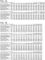
- Figs. 6 , 12, 13, 14 , and 15 are tables showing the results of estimation of the energy densities of the flow batteries 3000 in embodiment 3. These tables show the potential (V vs. Li/Li + ) of each mediator, the charge and discharge voltages (V) of each flow battery, the theoretical capacity density (Ah/L) of the flow battery, the theoretical energy density (Wh/L) of the flow battery, the volume filling factor of a power generation element, and the energy density (Wh/L) of the flow battery.
- Figs. 6 and 12 show the results of estimation of the energy densities of flow batteries 3000 in embodiment 3 under the conditions described above in the operation example when the charge mediator 111 is biphenyl or phenanthrene and the discharge mediator 112 is 2,2'-bipyridyl or trans-stilbene.
- the estimated energy density of the flow battery is 570 Wh/L.
- the estimated energy density of the flow battery is 589 Wh/L.
- the theoretical energy density of a conventional flow battery is about 38 Wh/L. As can be seen from these results, the theoretical energy density of the flow battery of the present disclosure is significantly higher than that of the conventional flow battery.
- Embodiment 4 will be described. However, the description will be omitted as appropriate when it overlaps with that of any of embodiments 1 to 3 above.
- Fig. 7 is a schematic illustration showing a general structure of a flow battery 4000 in embodiment 4.
- the flow battery 4000 in embodiment 4 includes, in addition to the structure of the flow battery 3000 in embodiment 3, the following structure.
- the flow battery 4000 in embodiment 4 includes the structure of the first circulator 510 shown in embodiment 2 above.
- the flow battery 4000 in embodiment 4 further includes the electrochemical reaction section 600, the positive electrode terminal 221, and the negative electrode terminal 211 shown in embodiment 2 above.
- the second circulator 520 includes a second container 521.
- the second active material 320 and the second liquid 120 are contained in the second container 521.
- the second circulator 520 circulates the second liquid 120 between the second electrode 220 and the second container 521.
- the second active material 320 comes into contact with the second liquid 120. This allows the second electrode-side mediator 121 to be oxidized and reduced by the second active material 320.
- the second liquid 120 and the second active material 320 can come into contact with each other in the second container 521.
- the area of contact between the second liquid 120 and the second active material 320 can be increased.
- the time of contact between the second liquid 120 and the second active material 320 can be increased. This allows the oxidation and reduction reactions of the second electrode-side mediator 121 by the second active material 320 to proceed more efficiently.
- the second container 521 may be, for example, a tank.
- the second liquid 120 containing the second electrode-side mediator 121 dissolved therein may be accommodated, for example, in spaces in the second active material 320 placed in the second container 521.
- the second circulator 520 may include a pipe 523, a pipe 524, and a pump 525.
- One end of the pipe 524 is connected to the positive electrode chamber 620 or the negative electrode chamber 610, whichever includes the second electrode 220 disposed therein (the positive electrode chamber 620 in the example shown in Fig. 7 ).
- the other end of the pipe 524 is connected to an inlet of the second liquid 120 that is disposed in the second container 521.
- One end of the pipe 523 is connected to an outlet of the second liquid 120 that is disposed in the second container 521.
- the other end of the pipe 523 is connected to the positive electrode chamber 620 or the negative electrode chamber 610, whichever includes the second electrode 220 disposed therein (the positive electrode chamber 620 in the example shown in Fig. 7 ).
- the pump 525 is disposed, for example, in the pipe 524. Alternatively, the pump 525 may be disposed in the pipe 523.
- the second circulator 520 may include a second passage prevention member 522.
- the second passage prevention member 522 prevents passage of the second active material 320.
- the second passage prevention member 522 is disposed in a channel through which the second liquid 120 flows from the second container 521 to the second electrode 220 (the pipe 523 in the example shown in Fig. 7 ).
- the above structure can prevent the second active material 320 from flowing out of the second container 521 (e.g., flowing into the second electrode 220 side). Specifically, the second active material 320 stays in the second container 521. Therefore, the flow battery provided can have a structure in which the second active material 320 itself is not circulated. This can prevent clogging of a component (e.g., a pipe) of the second circulator 520 with the second active material 320. Moreover, the occurrence of resistance loss caused by the second active material 320 flowing into the second electrode 220 side can be prevented.
- a component e.g., a pipe
- the second passage prevention member 522 may be disposed, for example, at the joint between the second container 521 and the pipe 523.
- the second passage prevention member 522 may be, for example, a filter that can filter out the second active material 320.
- the filter may be a member having pores smaller than the minimum diameter of the particles of the second active material 320.
- a material unreactive with the second active material 320, the second liquid 120, etc. can be used as the material of the filter.
- the filter may be, for example, glass fiber filter paper, polypropylene nonwoven fabric, polyethylene nonwoven fabric, or a metal mesh unreactive with lithium metal.
- the second liquid 120 contained in the second container 521 passes through the second passage prevention member 522 and the pipe 523 and is then supplied to the positive electrode chamber 620.
- the second electrode-side mediator 121 dissolved in the second liquid 120 is thereby oxidized or reduced on the second electrode 220.
- the second liquid 120 containing the oxidized or reduced second electrode-side mediator 121 dissolved therein passes through the pipe 524 and the pump 525 and is supplied to the second container 521.
- the second electrode-side mediator 121 dissolved in the second liquid 120 is oxidized or reduced by the second active material 320.
- the pump 525 may be used to control the circulation of the second liquid 120.
- the pump 525 may be used appropriately to start the supply of the second liquid 120, stop the supply, or control the amount of the supply.
- means e.g., a valve
- the pump 525 may be used to control the circulation of the second liquid 120.
- the first electrode 210 is shown as the negative electrode
- the second electrode 220 is shown as the positive electrode.
- the first electrode 210 can serve as a positive electrode.
- the first electrode 210 may be a positive electrode
- the second electrode 220 may be a negative electrode.
- Embodiment 5 will be described. However, the description will be omitted as appropriate when it overlaps with that of any of embodiments 1 to 4 above.
- a flow battery in embodiment 5 includes, in addition to the structures of the flow batteries in embodiments 1 to 4, the following structure.
- the first active material 310 contains zinc.
- the flow battery provided can have a higher capacity than the flow batteries using graphite as the first active material 310.
- the first active material 310 can have a relatively low equilibrium potential (vs. Li/Li + ). Therefore, a material having a relatively low equilibrium potential (vs. Li/Li + ) (e.g., a condensed aromatic compound) can be used as the discharge mediator 112.
- the flow battery negative electrode provided can have a lower potential. Therefore, the flow battery provided can have a high battery voltage (discharge voltage).
- the composition of lithium-occluding zinc (i.e., a LiZn alloy formed during charging) used as the first active material 310 may be at least one of LiZn, Li 2 Zn 3 , LiZn 2 , Li 2 Zn 5 , and LiZn 4 .
- a mediator-type negative electrode can be formed by using as the charge mediator a condensed aromatic compound having a lower potential than the LiZn alloy and using as the discharge mediator a condensed aromatic compound having a higher potential than the LiZn alloy.
- the charge mediator 111 may be at least one selected from the group consisting of phenanthrene, biphenyl, O-terphenyl, triphenylene, anthracene, acenaphthene, acenaphthylene, fluoranthene, and benzil.
- the charge mediator 111 provided can be electrochemically base. More specifically, the charge mediator provided can have a lower potential (vs. Li/Li + ) than the LiZn alloy.
- the discharge mediator 112 may be at least one selected from the group consisting of 1,10-phenanthroline, 2,2'-bipyridyl, benzophenone, trans-stilbene, 4,4'-bipyridyl, 3,3'-bipyridyl, 2,4'-bipyridyl, 2,3'-bipyridyl, cis-stilbene, acetophenone, propiophenone, butyrophenone, valerophenone, ethylenediamine, and tetraphenylcyclopentadienone.
- the discharge mediator 112 provided can be electrochemically noble. More specifically, the discharge mediator 112 provided can have a higher potential (vs. Li/Li + ) than the LiZn alloy.
- the discharge mediator 112 may be at least one selected from the group consisting of 2,2'-bipyridyl, trans-stilbene, 2,4'-bipyridyl, 2,3'-bipyridyl, cis-stilbene, propiophenone, butyrophenone, valerophenone, ethylenediamine, and tetraphenylcyclopentadienone.
- the discharge mediator 112 provided can be electrochemically noble. More specifically, the discharge mediator 112 provided can have a higher potential (vs. Li/Li + ) than the LiZn alloy. Moreover, the discharge mediator 112 can have a relatively low equilibrium potential (vs. Li/Li + ). In this case, the flow battery negative electrode provided can have a lower potential. Therefore, the flow battery provided can have a high battery voltage (discharge voltage).
- the first active material 310 is zinc (LiZn).
- Processes other than the following processes may be the same as those in the charge and discharge processes described in embodiment 1 or 3 above.
- the charge mediator 111 reduced on the first electrode 210 is oxidized by the first active material 310.
- the first active material 310 is reduced by the charge mediator 111.
- zinc serving as the first active material 310 reacts with lithium to form LiZn.
- the discharge mediator 112 oxidized on the first electrode 210 is reduced by the first active material 310.
- the first active material 310 is oxidized by the discharge mediator 112.
- the first active material 310 releases lithium.
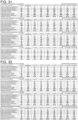
- Figs. 16 and 17 are tables showing the results of estimation of the energy densities of the flow batteries in embodiment 5. These tables show the potential (V vs. Li/Li + ) of each mediator, the charge and discharge voltages (V) of each flow battery, the theoretical capacity density (Ah/L) of the flow battery, the theoretical energy density (Wh/L) of the flow battery, the volume filling factor of a power generation element, and the energy density (Wh/L) of the flow battery.
- Embodiment 6 will be described. However, the description will be omitted as appropriate when it overlaps with that of any of embodiments 1 to 4 above.
- a flow battery in embodiment 6 includes, in addition to the structures of the flow batteries in embodiments 1 to 4, the following structure.
- the first active material 310 contains tin.
- the flow battery provided can have a higher capacity than the flow batteries using graphite as the first active material 310.
- the first active material 310 can have a relatively low equilibrium potential (vs. Li/Li + ). Therefore, a material having a relatively low equilibrium potential (vs. Li/Li + ) (e.g., a condensed aromatic compound) can be used as the discharge mediator 112.
- the flow battery negative electrode provided can have a lower potential. Therefore, the flow battery provided can have a high battery voltage (discharge voltage).
- the composition of lithium-occluding tin (i.e., a LiSn alloy formed during charging) used as the first active material 310 may be at least one of LiSn, Li 2 Sn 5 , Li 5 Sn 2 , Li 7 Sn 2 , Li 7 Sn 3 , Li 13 Sn 5 , and Li 22 Sn 5 .
- a mediator-type negative electrode can be formed by using as the charge mediator a condensed aromatic compound having a lower potential than the LiSn alloy and using as the discharge mediator a condensed aromatic compound having a higher potential than the LiSn alloy.
- the charge mediator 111 may be at least one selected from the group consisting of phenanthrene, biphenyl, O-terphenyl, triphenylene, anthracene, acenaphthene, acenaphthylene, fluoranthene, 2,2'-bipyridyl, trans-stilbene, cis-stilbene, propiophenone, butyrophenone, valerophenone, ethylenediamine, benzil, and tetraphenylcyclopentadienone.
- the charge mediator 111 provided can be electrochemically base. More specifically, the charge mediator provided can have a lower potential (vs. Li/Li + ) than the LiSn alloy.
- the discharge mediator 112 may be at least one selected from the group consisting of 1,10-phenanthroline, benzophenone, 4,4'-bipyridyl, 3,3'-bipyridyl, 2,4'-bipyridyl, 2,3'-bipyridyl, and acetophenone.
- the discharge mediator 112 provided can be electrochemically noble. More specifically, the discharge mediator 112 provided can have a higher potential (vs. Li/Li + ) than the LiSn alloy.
- the discharge mediator 112 may be at least one selected from the group consisting of benzophenone, 2,4'-bipyridyl, and 2,3'-bipyridyl.
- the discharge mediator 112 provided can be electrochemically noble. More specifically, the discharge mediator 112 provided can have a higher potential (vs. Li/Li + ) than the LiSn alloy. Moreover, the discharge mediator 112 can have a relatively low equilibrium potential (vs. Li/Li + ). In this case, the flow battery negative electrode provided can have a lower potential. Therefore, the flow battery provided can have a high battery voltage (discharge voltage).
- the first active material 310 is tin (LiSn).
- Processes other than the following processes may be the same as those in the charge and discharge processes described in embodiment 1 or 3 above.
- the charge mediator 111 reduced on the first electrode 210 is oxidized by the first active material 310.
- the first active material 310 is reduced by the charge mediator 111.
- tin serving as the first active material 310 reacts with lithium to form LiSn.
- the discharge mediator 112 oxidized on the first electrode 210 is reduced by the first active material 310.
- the first active material 310 is oxidized by the discharge mediator 112.
- the first active material 310 releases lithium.
- Figs. 18 , 19 , 20 , and 21 are tables showing the results of estimation of the energy densities of the flow batteries in embodiment 6. These tables show the potential (V vs. Li/Li + ) of each mediator, the charge and discharge voltages (V) of each flow battery, the theoretical capacity density (Ah/L) of the flow battery, the theoretical energy density (Wh/L) of the flow battery, the volume filling factor of a power generation element, and the energy density (Wh/L) of the flow battery.
- Embodiment 7 will be described. However, the description will be omitted as appropriate when it overlaps with that of any of embodiments 1 to 5 above.
- a flow battery in embodiment 7 includes, in addition to the structures of the flow batteries in embodiments 1 to 4, the following structure.
- the first active material 310 contains germanium.
- the flow battery provided can have a higher capacity than the flow batteries using graphite as the first active material 310.
- the first active material 310 can have a relatively low equilibrium potential (vs. Li/Li + ). Therefore, a material having a relatively low equilibrium potential (vs. Li/Li + ) (e.g., a condensed aromatic compound) can be used as the discharge mediator 112.
- the flow battery negative electrode provided can have a lower potential. Therefore, the flow battery provided can have a high battery voltage (discharge voltage).
- the composition of lithium-occluding germanium (i.e., a LiGe alloy formed during charging) used as the first active material 310 may be at least one of GeLi 3 and Ge 5 Li 22 .
- a mediator-type negative electrode can be formed by using as the charge mediator a condensed aromatic compound having a lower potential than the LiGe alloy and using as the discharge mediator a condensed aromatic compound having a higher potential than the LiGe alloy.
- the charge mediator 111 may be at least one selected from the group consisting of phenanthrene, biphenyl, O-terphenyl, triphenylene, anthracene, acenaphthene, acenaphthylene, fluoranthene, 2,2'-bipyridyl, trans-stilbene, cis-stilbene, propiophenone, butyrophenone, valerophenone, ethylenediamine, benzil, and tetraphenylcyclopentadienone.
- the charge mediator 111 provided can be electrochemically base. More specifically, the charge mediator provided can have a lower potential (vs. Li/Li + ) than the LiGe alloy.
- the discharge mediator 112 may be at least one selected from the group consisting of 1,10-phenanthroline, benzophenone, 4,4'-bipyridyl, 3,3'-bipyridyl, 2,4'-bipyridyl, 2,3'-bipyridyl, and acetophenone.
- the discharge mediator 112 provided can be electrochemically noble. More specifically, the discharge mediator 112 provided can have a higher potential (vs. Li/Li + ) than the LiGe alloy.
- the discharge mediator 112 may be at least one selected from the group consisting of benzophenone, 2,4'-bipyridyl, and 2,3'-bipyridyl.
- the discharge mediator 112 provided can be electrochemically noble. More specifically, the discharge mediator 112 provided can have a higher potential (vs. Li/Li + ) than the LiGe alloy. Moreover, the discharge mediator 112 can have a relatively low equilibrium potential (vs. Li/Li + ). In this case, the flow battery negative electrode provided can have a lower potential. Therefore, the flow battery provided can have a high battery voltage (discharge voltage).
- the first active material 310 is germanium (GeLi 3 ).
- Processes other than the following processes may be the same as those in the charge and discharge processes described in embodiment 1 or 3 above.
- the charge mediator 111 reduced on the first electrode 210 is oxidized by the first active material 310.
- the first active material 310 is reduced by the charge mediator 111.
- germanium serving as the first active material 310 reacts with lithium to form GeLi 3 .
- the discharge mediator 112 oxidized on the first electrode 210 is reduced by the first active material 310.
- the first active material 310 is oxidized by the discharge mediator 112.
- the first active material 310 releases lithium.
- Figs. 22 , 23 , 24 , and 25 are tables showing the results of estimation of the energy densities of the flow batteries in embodiment 7. These tables show the potential (V vs. Li/Li + ) of each mediator, the charge and discharge voltages (V) of each flow battery, the theoretical capacity density (Ah/L) of the flow battery, the theoretical energy density (Wh/L) of the flow battery, the volume filling factor of a power generation element, and the energy density (Wh/L) of the flow battery.
- Embodiment 8 will be described. However, the description will be omitted as appropriate when it overlaps with that of any of embodiments 1 to 4 above.
- a flow battery in embodiment 8 includes, in addition to the structures of the flow batteries in embodiments 1 to 4, the following structure.
- the first active material 310 contains aluminum.
- the flow battery provided can have a higher capacity than the flow batteries using graphite as the first active material 310.
- the first active material 310 can have a relatively low equilibrium potential (vs. Li/Li + ). Therefore, a material having a relatively low equilibrium potential (vs. Li/Li + ) (e.g., a condensed aromatic compound) can be used as the discharge mediator 112.
- the flow battery negative electrode provided can have a lower potential. Therefore, the flow battery provided can have a high battery voltage (discharge voltage).
- the composition of lithium-occluding aluminum (i.e., a LiAl alloy formed during charging) used as the first active material 310 may be LiAl.
- a mediator-type negative electrode can be formed by using as the charge mediator a condensed aromatic compound having a lower potential than the LiAl alloy and using as the discharge mediator a condensed aromatic compound having a higher potential than the LiAl alloy.
- the charge mediator 111 may be at least one selected from the group consisting of phenanthrene, biphenyl, O-terphenyl, triphenylene, anthracene, acenaphthene, acenaphthylene, fluoranthene, trans-stilbene, butyrophenone, valerophenone, ethylenediamine, benzil, and tetraphenylcyclopentadienone.
- the charge mediator 111 provided can be electrochemically base. More specifically, the charge mediator provided can have a lower potential (vs. Li/Li + ) than the LiAl alloy.
- the discharge mediator 112 may be at least one selected from the group consisting of 1,10-phenanthroline, 2,2'-bipyridyl, benzophenone, 4,4'-bipyridyl, 3,3'-bipyridyl, 2,4'-bipyridyl, 2,3'-bipyridyl, cis-stilbene, acetophenone, and propiophenone.
- the discharge mediator 112 provided can be electrochemically noble. More specifically, the discharge mediator 112 provided can have a higher potential (vs. Li/Li + ) than the LiAl alloy.
- the discharge mediator 112 may be at least one selected from the group consisting of 2,2'-bipyridyl, benzophenone, 2,4'-bipyridyl, 2,3'-bipyridyl, cis-stilbene, and propiophenone.
- the discharge mediator 112 provided can be electrochemically noble. More specifically, the discharge mediator 112 provided can have a higher potential (vs. Li/Li + ) than the LiAl alloy. Moreover, the discharge mediator 112 can have a relatively low equilibrium potential (vs. Li/Li + ). In this case, the flow battery negative electrode provided can have a lower potential. Therefore, the flow battery provided can have a high battery voltage (discharge voltage).
- the first active material 310 is aluminum (LiAl).
- Processes other than the following processes may be the same as those in the charge and discharge processes described in embodiment 1 or 3 above.
- the charge mediator 111 reduced on the first electrode 210 is oxidized by the first active material 310.
- the first active material 310 is reduced by the charge mediator 111.
- aluminum serving as the first active material 310 reacts with lithium to form LiAl.
- the discharge mediator 112 oxidized on the first electrode 210 is reduced by the first active material 310.
- the first active material 310 is oxidized by the discharge mediator 112.
- the first active material 310 releases lithium.
- Figs. 26 , 27 , 28 , and 29 are tables showing the results of estimation of the energy densities of the flow batteries in embodiment 8. These tables show the potential (V vs. Li/Li + ) of each mediator, the charge and discharge voltages (V) of each flow battery, the theoretical capacity density (Ah/L) of the flow battery, the theoretical energy density (Wh/L) of the flow battery, the volume filling factor of a power generation element, and the energy density (Wh/L) of the flow battery.
- Embodiment 9 will be described. However, the description will be omitted as appropriate when it overlaps with that of any of embodiments 1 to 5 above.
- a flow battery in embodiment 9 includes, in addition to the structures of the flow batteries in embodiments 1 to 4, the following structure.
- the first active material 310 contains silicon.
- the flow battery provided can have a higher capacity than the flow batteries using graphite as the first active material 310.
- the first active material 310 can have a relatively low equilibrium potential (vs. Li/Li + ). Therefore, a material having a relatively low equilibrium potential (vs. Li/Li + ) (e.g., a condensed aromatic compound) can be used as the discharge mediator 112.
- the flow battery negative electrode provided can have a lower potential. Therefore, the flow battery provided can have a high battery voltage (discharge voltage).
- the composition of lithium-occluding silicon (i.e., a LiSi alloy formed during charging) used as the first active material 310 may be at least one of Li 7 Si 3 , Li 12 Si 7 , Li 13 Si 4 , and Li 22 Si 5 .
- a mediator-type negative electrode can be formed by using as the charge mediator a condensed aromatic compound having a lower potential than the LiSi alloy and using as the discharge mediator a condensed aromatic compound having a higher potential than the LiSi alloy.
- the charge mediator 111 may be at least one selected from the group consisting of phenanthrene, biphenyl, O-terphenyl, triphenylene, anthracene, acenaphthene, acenaphthylene, fluoranthene, trans-stilbene, butyrophenone, valerophenone, ethylenediamine, benzil, and tetraphenylcyclopentadienone.
- the charge mediator 111 provided can be electrochemically base. More specifically, the charge mediator provided can have a lower potential (vs. Li/Li + ) than the LiSi alloy.
- the discharge mediator 112 may be at least one selected from the group consisting of 1,10-phenanthroline, 2,2'-bipyridyl, benzophenone, 4,4'-bipyridyl, 3,3'-bipyridyl, 2,4'-bipyridyl, 2,3'-bipyridyl, cis-stilbene, acetophenone, and propiophenone.
- the discharge mediator 112 provided can be electrochemically noble. More specifically, the discharge mediator 112 provided can have a higher potential (vs. Li/Li + ) than the LiSi alloy.
- the discharge mediator 112 may be at least one selected from the group consisting of 2,2'-bipyridyl, benzophenone, 2,4'-bipyridyl, 2,3'-bipyridyl, cis-stilbene, and propiophenone.
- the discharge mediator 112 provided can be electrochemically noble. More specifically, the discharge mediator 112 provided can have a higher potential (vs. Li/Li + ) than the LiSi alloy. Moreover, the discharge mediator 112 can have a relatively low equilibrium potential (vs. Li/Li + ). In this case, the flow battery negative electrode provided can have a lower potential. Therefore, the flow battery provided can have a high battery voltage (discharge voltage).
- the first active material 310 is silicon (Li 7 Si 3 ).
- Processes other than the following processes may be the same as those in the charge and discharge processes described in embodiment 1 or 3 above.
- the charge mediator 111 reduced on the first electrode 210 is oxidized by the first active material 310.
- the first active material 310 is reduced by the charge mediator 111.
- silicon serving as the first active material 310 reacts with lithium to form Li 7 Si 3 .
- the discharge mediator 112 oxidized on the first electrode 210 is reduced by the first active material 310.
- the first active material 310 is oxidized by the discharge mediator 112.
- the first active material 310 releases lithium.
- Figs. 30 , 31 , 32 , and 33 are tables showing the results of estimation of the energy densities of the flow batteries in embodiment 9. These tables show the potential (V vs. Li/Li + ) of each mediator, the charge and discharge voltages (V) of each flow battery, the theoretical capacity density (Ah/L) of the flow battery, the theoretical energy density (Wh/L) of the flow battery, the volume filling factor of a power generation element, and the energy density (Wh/L) of the flow battery.
- each flow battery in embodiment 9 is significantly higher than that of the conventional flow battery.
- Embodiment 10 will be described. However, the description will be omitted as appropriate when it overlaps with that of any of embodiments 1 to 4 above.
- a flow battery in embodiment 10 includes, in addition to the structure of the above-described flow battery 1000 in embodiment 1, the following structure.
- the flow battery in embodiment 10 includes the first liquid 110, the first electrode 210, the first active material 310, a second liquid 120, the second electrode 220, and an electrolyte salt.
- the first liquid 110 includes dissolved therein the charge mediator 111 and the discharge mediator 112.
- the first electrode 210 is immersed in the first liquid 110.
- the first active material 310 is immersed in the first liquid 110.
- the second electrode 220 is a counter electrode of the first electrode 210.
- the second electrode 220 is immersed in the second liquid 120.
- the equilibrium potential of the charge mediator 111 is lower than the equilibrium potential of the first active material 310.
- the equilibrium potential of the discharge mediator 112 is higher than the equilibrium potential of the first active material 310.
- the electrolyte salt is dissolved in at least one of the first liquid 110 and the second liquid 120.
- the concentration of the electrolyte salt in the first liquid 110 is equal to or lower than the concentration of the charge mediator 111 in the first liquid 110.
- the flow battery provided can have a high energy density.
- the concentration of the electrolyte salt in the first liquid 110 is set to be equal to or lower than the concentration of the charge mediator 111
- the equilibrium potential of the charge mediator 111 can be easily maintained.
- a significant increase in the equilibrium potential of the charge mediator 111 an increase caused by the electrolyte salt
- the charge mediator 111 can reduce the first active material 310. This allows the flow battery provided to utilize the capacity of the first active material 310. Therefore, the flow battery provided can have a high energy density.
- the electrolyte salt is dissolved in at least one liquid of the first liquid 110 and the second liquid 120. This can increase the ion conductivity of the at least one liquid.
- the concentration of the electrolyte salt in the first liquid 110 may be lower than the concentration of the charge mediator 111 in the first liquid 110.
- the equilibrium potential of the charge mediator 111 can be easily maintained. In other words, a significant increase in the equilibrium potential of the charge mediator 111 (an increase caused by the electrolyte salt) can be further prevented. Therefore, the flow battery provided can have a higher energy density.
- the concentration of the electrolyte salt in the first liquid 110 may be equal to or lower than the concentration of the discharge mediator 112 in the first liquid 110.
- the flow battery provided can have a higher battery voltage (discharge voltage) and a higher energy density.
- the concentration of the electrolyte salt in the first liquid 110 is set to be equal to or lower than the concentration of the discharge mediator 112, the equilibrium potential of the discharge mediator 112 can be easily maintained. In other words, a significant increase in the equilibrium potential of the discharge mediator 112 (an increase caused by the electrolyte salt) can be prevented.
- the flow battery negative electrode provided can have a lower potential. Therefore, the flow battery provided can have a higher battery voltage (discharge voltage).
- the concentration of the electrolyte salt in the first liquid 110 may be lower than the concentration of the discharge mediator 112 in the first liquid 110.
- the equilibrium potential of the discharge mediator 112 can be easily maintained. In other words, a significant increase in the equilibrium potential of the discharge mediator 112 (an increase caused by the electrolyte salt) can be further prevented.
- the flow battery negative electrode provided can have a lower potential. Therefore, the flow battery provided can have a higher battery voltage (discharge voltage).
- the flow battery in embodiment 10 may further include the separator 400.
- the separator 400 separates the first electrode 210 and the first liquid 110 from the second electrode 220 and the second liquid 120.
- the concentration of the electrolyte salt in the first liquid 110 may be lower than the concentration of the electrolyte salt in the second liquid 120.
- the flow battery provided can have a high battery voltage (discharge voltage). Moreover, the flow battery provided can have a high energy density.
- the electrolyte salt may be dissolved in the second liquid 120.
- the electrolyte salt may not be dissolved in the first liquid 110.
- the concentration of the electrolyte salt in the first liquid 110 may be 0M.
- the equilibrium potentials of the charge mediator 111 and the discharge mediator 112 can be easily maintained (changes in the equilibrium potentials can be further reduced). Therefore, the flow battery provided can have a higher battery voltage (discharge voltage). Moreover, the flow battery provided can have a higher energy density.
- the first electrode 210 may be a negative electrode
- the second electrode 220 may be a positive electrode
- the electrolyte salt may be a lithium salt.
- the lithium salt used may be LiBF 4 , LiSbF 6 , LiAsF 6 , LiCF 3 SO 3 , LiN(SO 2 CF 3 ) 2 , LiN(SO 2 C 2 F 5 ) 2 , LiN(SO 2 CF 3 )(SO 2 C 4 F 9 ), LiC(SO 2 CF 3 ) 3 , or LiN(SO 2 F) 2 .
- the lithium salt used may be one selected from these lithium salts. Alternatively, a mixture of two or more selected from these lithium salts may be used.
- the electrolyte salt may be at least one selected from the group consisting of LiBF 4 , LiN(SO 2 CF 3 ) 2 , LiN(SO 2 F) 2 , and LiCF 3 SO 3 .
- Figs. 34, 35, 36, and 37 are tables showing the results of measurement of the potentials of biphenyl solutions.
- Each sample was prepared by dissolving biphenyl, i.e., a condensed aromatic compound, and an electrolyte salt in a 2-methyltetrahydrofuran (2MeTHF) solution at molar concentrations (M) shown in one of the tables.
- 2MeTHF 2-methyltetrahydrofuran
- LiBF 4 was used as the electrolyte salt.
- LiN(SO 2 CF 3 ) 2 was uses as the electrolyte salt.
- LiN(SO 2 F) 2 was used as the electrolyte salt.
- LiCF 3 SO 3 was used as the electrolyte salt.
- Potential measurement cells containing respective samples poured therein were produced, and the potential of each cell was measured. The potentials (V vs. Li/Li + ) measured with respect to lithium metal are shown in the tables.
- the concentration of the electrolyte salt is equal to or lower than the concentration of biphenyl
- a significant increase in the equilibrium potential of biphenyl is prevented.
- the concentration of the electrolyte salt is equal to or lower than the concentration of biphenyl
- the equilibrium potential of biphenyl can be maintained at 0.2 V vs. Li/Li + or lower.
- Fig. 38 is a table showing the results of measurement of the potentials of trans-stilbene solutions.
- Each sample was prepared by dissolving trans-stilbene, i.e., a condensed aromatic compound, and LiBF 4 , i.e., an electrolyte salt, in a 2-methyltetrahydrofuran (2MeTHF) solution at molar concentrations shown in Fig. 38 .
- Trans-stilbene i.e., a condensed aromatic compound
- LiBF 4 i.e., an electrolyte salt
- 2MeTHF 2-methyltetrahydrofuran
- the concentration of the electrolyte salt is equal to or lower than the concentration of trans-stilbene, a significant increase in the equilibrium potential of trans-stilbene is prevented.
- the concentration of electrolyte salt is equal to or lower than the concentration of trans-stilbene, the equilibrium potential of trans-stilbene can be maintained within the range of 0.2 to 0.6 V vs. Li/Li + .
- Fig. 39 is a table showing the results of estimation of the energy densities of the flow batteries in embodiment 10.
- Fig. 39 shows the results of estimation of the energy densities under the conditions described above in the operation example of the charge and discharge processes of the flow battery 3000 in embodiment 3 when the charge mediator 111 of the negative electrode is biphenyl and the discharge mediator 112 of the negative electrode is trans-stilbene.
- the concentration of biphenyl in the first liquid 110 is 0.1M.
- the concentration of trans-stilbene in the first liquid 110 is 0.1M.
- “Computational example A” in Fig. 39 is a computational example under the condition that the electrolyte salt is not dissolved in the first liquid 110. Under the condition in “computational example A,” an increase in the potential of the charge mediator of the negative electrode and an increase in the potential of the discharge mediator of the negative electrode (increases caused by the electrolyte salt) do not occur. Therefore, the discharge voltage of the flow battery is high (3.1 V). The estimated energy density of the flow battery is 589 Wh/L.
- “Computational example B” in Fig. 39 is a computational example under the condition that LiBF 4 , i.e., the electrolyte salt, is dissolved in the first liquid 110 at a concentration of "0.05M.” Under the condition in “computational example B,” although the potential of the charge mediator of the negative electrode and the potential of the discharge mediator of the negative electrode are increased slightly (increases caused by the electrolyte salt), the potentials are not increased significantly. Therefore, the discharge voltage of the flow battery is high (3.07 V). The estimated energy density of the flow battery is 584 Wh/L. Since the electrolyte salt is dissolved in the first liquid 110, the ion conductivity of the first liquid 110 is improved.
- “Computational example C” in Fig. 39 is a computational example under the condition that LiBF 4 , i.e., the electrolyte salt, is dissolved in the first liquid 110 at a concentration of "0.1M.”
- the discharge voltage of the flow battery is high (2.98 V).
- the estimated energy density of the flow battery is 567 Wh/L. Since the electrolyte salt is dissolved in the first liquid 110, the ion conductivity of the first liquid 110 is improved.
- “Computational example D” in Fig. 39 is a computational example under the condition that LiBF 4 , i.e., the electrolyte salt, is dissolved in the first liquid 110 at a concentration of "1M.”
- the potential of the discharge mediator (trans-stilbene) is significantly increased to 1.3 V vs. Li/Li + because of the electrolyte salt. Therefore, the discharge voltage of the flow battery is decreased to 2.1 V.
- the potential of the charge mediator (biphenyl) of the negative electrode is significantly increased to 1.2 V vs. Li/Li + because of the electrolyte salt. Therefore, the equilibrium potential of the charge mediator of the negative electrode is higher than the equilibrium potential (0.15 V vs.
- the first active material 310 graphite: C 6 Li.
- the charge mediator is reduced by the first electrode 210, the first active material 310 is not reduced by the charge mediator (C 6 Li is not formed). Therefore, the capacity of the first active material 310 cannot be utilized. In this case, only the mediators dissolved in the first liquid 110 contribute to the battery capacity. This may be the cause of the significant reduction in battery capacity and energy density.
- Embodiment 11 will be described. However, the description will be omitted as appropriate when it overlaps with that of any of embodiments 1 to 4 above.
- a flow battery in embodiment 11 includes, in addition to the structure of the above-described flow battery 1000 in embodiment 1, the following structure.
- the flow battery in embodiment 11 includes the first liquid 110, the first electrode 210, and the first active material 310.
- the first liquid 110 contains dissolved therein the charge mediator 111, the discharge mediator 112, and an electrolyte salt.
- the first electrode 210 is immersed in the first liquid 110.
- the first active material 310 is immersed in the first liquid 110.
- the equilibrium potential of the charge mediator 111 is lower than the equilibrium potential of the first active material 310.
- the equilibrium potential of the discharge mediator 112 is higher than the equilibrium potential of the first active material 310.
- the electrolyte salt dissolved in the first liquid 110 is LiPF 6 .
- the flow battery provided can have a high energy density.
- the electrolyte salt in the first liquid 110 is LiPF 6
- the equilibrium potential of the charge mediator 111 can be maintained even when the concentration of the electrolyte salt is set arbitrarily relative to the concentration of the charge mediator 111.
- the ion conductivity can be improved by the addition of a sufficient amount of LiPF 6 .
- This can increase the ion conductivity while the equilibrium potential of the charge mediator 111 is prevented from exceeding the equilibrium potential of the first active material 310.
- the flow battery provided can utilize the capacity of the first active material 310. Therefore, the flow battery provided can have a high energy density.
- the flow battery provided can have a higher battery voltage (discharge voltage) and a higher energy density.
- the electrolyte salt in the first liquid 110 is LiPF 6
- the equilibrium potential of the discharge mediator 112 can be maintained.
- the ion conductivity can be improved by the addition of a sufficient amount of LiPF 6 . Therefore, the flow battery negative electrode provided can have a lower potential while the ion conductivity is increased.
- the flow battery provided can thereby have a higher battery voltage (discharge voltage).
- the flow battery in embodiment 11 may further include a second liquid 120 and the second electrode 220.
- the second electrode 220 is a counter electrode of the first electrode 210.
- the second electrode 220 is immersed in the second liquid 120.
- LiPF 6 i.e., the electrolyte salt
- the second liquid 120 LiPF 6 , i.e., the electrolyte salt
- LiPF 6 i.e., the electrolyte salt
- the electrolyte salt is dissolved in at least one of the first liquid 110 and the second liquid 120, and the ion conductivity of the liquid can thereby be increased.
- the flow battery in embodiment 11 may further include the separator 400.
- the separator 400 separates the first electrode 210 and the first liquid 110 from the second electrode 220 and the second liquid 120.
- the equilibrium potentials of the charge mediator 111 and the discharge mediator 112 can be easily maintained (changes in the equilibrium potentials can be further reduced). Therefore, the flow battery provided can have a higher battery voltage (discharge voltage). Moreover, the flow battery provided can have a higher energy density.
- the first electrode 210 may be a negative electrode
- the second electrode 220 may be a positive electrode
- Fig. 40 is a table showing the results of measurement of the potentials of biphenyl solutions.
- Each sample was prepared by dissolving biphenyl, i.e., a condensed aromatic compound, and LiPF 6 , i.e., an electrolyte salt, in a 2-methyltetrahydrofuran (2MeTHF) solution at molar concentrations (M) shown in Fig. 40 .
- 2MeTHF 2-methyltetrahydrofuran
- Potential measurement cells containing respective samples poured therein were produced, and the potential of each cell was measured.
- Fig. 40 shows the potentials (V vs. Li/Li + ) measured with respect to lithium metal. As shown in Fig.
- the equilibrium potential of biphenyl with respect to the potential of lithium metal can be maintained at 0.2 V vs. Li/Li + or lower.
- Fig. 41 is a table showing the results of measurement of the potentials of trans-stilbene solutions.
- Each sample was prepared by dissolving trans-stilbene, i.e., a condensed aromatic compound, and LiPF 6 , i.e., an electrolyte salt, in a 2-methyltetrahydrofuran (2MeTHF) solution at molar concentrations (M) shown in Fig. 41 .
- Trans-stilbene i.e., a condensed aromatic compound
- LiPF 6 i.e., an electrolyte salt
- 2MeTHF 2-methyltetrahydrofuran
- Fig. 42 is a table showing the results of estimation of the energy densities of the flow batteries in embodiment 11.
- Fig. 42 shows the results of estimation of the energy densities under the conditions described above in the operation example of the charge and discharge processes of the flow battery 3000 in embodiment 3 when the charge mediator 111 of the negative electrode is biphenyl and the discharge mediator 112 of the negative electrode is trans-stilbene.
- the concentration of biphenyl in the first liquid 110 is 0.1M.
- the concentration of trans-stilbene in the first liquid 110 is 0.1M.
- “Computational example E” in Fig. 42 is a computational example under the condition that the electrolyte salt is not dissolved in the first liquid 110. Under the condition in “computational example E,” an increase in the potential of the charge mediator of the negative electrode and an increase in the potential of the discharge mediator of the negative electrode (increases caused by the electrolyte salt) do not occur. Therefore, the discharge voltage of the flow battery is high (3.1 V). The estimated energy density of the flow battery is 589 Wh/L.
- “Computational example F” in Fig. 42 is a computational example under the condition that LiPF 6 , i.e., the electrolyte salt, is dissolved in the first liquid 110 at a concentration of "1M.” Under the condition in “computational example F,” the charge mediator of the negative electrode is increased slightly, and the potential of the discharge mediator of the negative electrode is decreased slightly, so the potentials are not changed significantly. Therefore, the discharge voltage of the flow battery is high (3.11 V). The estimated energy density of the flow battery is 591 Wh/L. Since the electrolyte salt is dissolved in the first liquid 110, the ion conductivity of the first liquid 110 is improved.
- “Computational example G” in Fig. 42 is a computational example under the condition that LiPF 6 , i.e., the electrolyte salt, is dissolved in the first liquid 110 at a concentration of "0.1M.” Under the condition in “computational example G,” the charge mediator of the negative electrode is increased slightly, and the potential of the discharge mediator of the negative electrode is decreased slightly, so the potentials are not changed significantly. Therefore, the discharge voltage of the flow battery is high (3.15 V). The estimated energy density of the flow battery is 599 Wh/L. Since the electrolyte salt is dissolved in the first liquid 110, the ion conductivity of the first liquid 110 is improved.
- Embodiment 12 will be described. However, the description will be omitted as appropriate when it overlaps with that of any of embodiments 1 to 4 above.
- a flow battery in embodiment 12 includes, in addition to the structure of the flow battery in any of embodiments 1 to 4 above, the following structure.
- the first liquid 110 is prepared by dissolving a condensed aromatic compound in at least one selected from the group consisting of tetrahydrofuran, 2 methyl-tetrahydrofuran, 1,2 dimethoxyethane, 2,5-dimethyltetrahydrofuran, diethoxyethane, dibutoxyethane, diethylene glycol dimethyl ether, triethylene glycol dimethyl ether, tetraethylene glycol dimethyl ether, 3 methylsulfolane, and tetrahydrofurfurylamine.
- a condensed aromatic compound in at least one selected from the group consisting of tetrahydrofuran, 2 methyl-tetrahydrofuran, 1,2 dimethoxyethane, 2,5-dimethyltetrahydrofuran, diethoxyethane, dibutoxyethane, diethylene glycol dimethyl ether, triethylene glycol dimethyl ether, tetraethylene glycol dimethyl ether, 3 methylsulf
- the first liquid 110 provided can have the function of stabilizing solvated electrons released from lithium and paired with the condensed aromatic compound and can dissolve lithium (e.g., lithium metal).
- Fig. 43 is a table showing samples of the first liquid.
- Biphenyl used as the condensed aromatic compound was dissolved in the samples (solvents) shown in Fig. 43 at a concentration of 0.1M to prepare solutions, and lithium metal pieces were added to the prepared solutions. Each solution was left to stand, and dissolution of lithium metal was visually checked.
- lithium metal gives solvated electrons to a colorless solution and dissolves as lithium ions, the solution is colored.
- the occurrence of dissolution of lithium metal can be determined by disappearance of the lithium metal.
- a graphite electrode formed into a strip shape (prepared by applying graphite powder to a Cu foil and then rolling the foil) was immersed in one of the solutions containing lithium metal dissolved therein for 4 days. Then the graphite electrode was removed from the solution, and a change in color of the graphite electrode and its surface state were observed.
- Fig. 44 is a table showing other samples of the first liquid.
- Each sample shown in Fig. 44 was prepared by mixing a solvent X and a solvent Y shown in Fig. 44 at a volume mixing ratio shown in Fig. 44 .
- the flow battery of the present disclosure can be preferably used as an electricity storage device.
Landscapes
- Chemical & Material Sciences (AREA)
- Engineering & Computer Science (AREA)
- General Chemical & Material Sciences (AREA)
- Electrochemistry (AREA)
- Chemical Kinetics & Catalysis (AREA)
- Sustainable Development (AREA)
- Sustainable Energy (AREA)
- Life Sciences & Earth Sciences (AREA)
- Manufacturing & Machinery (AREA)
- Dispersion Chemistry (AREA)
- Materials Engineering (AREA)
- Fuel Cell (AREA)
- Hybrid Cells (AREA)
- Secondary Cells (AREA)
- Battery Electrode And Active Subsutance (AREA)
Description
- The present disclosure relates to a flow battery.
-
PTL 1 discloses a redox flow battery that uses a negative electrode slurry solution containing a non-aqueous solvent and metal particles serving as solid negative electrode active material particles. - PTL 1:
Japanese Patent No. 5417441 -
US 2015/0255803 A1 discloses polyarene mediators for a mediated redox flow battery. In a general, according toUS 2015/0255803 A1 , a mediated redox flow battery includes a series of secondary organic molecules that form highly reduced anionic radicals as reaction mediator pairs for the reduction and oxidation of primary high capacity redox species ex situ from the electrochemical cell stack. Arenes are reduced to stable anionic radicals that in turn reduce a primary anode to the charged state. The primary anode is then discharged using a second lower potential (more positive) arene. Compatible separators and solvents are also disclosed inUS 2015/0255803 A1 . - Redox flow devices are described in
US 201110189520 A1 - In order to further increase charge and discharge capacities in an aqueous solution system, according to
JP 2016-085955 A - There is a need in the related art to provide a high-energy density flow battery.
- A flow battery according to the present invention is defined in
claim 1. Preferred embodiments are defined in the dependent claims. - The present disclosure can provide a high-energy density flow battery.
-
- [
Fig. 1] Fig. 1 is a block diagram showing a general structure of aflow battery 1000 inembodiment 1. - [
Fig. 2] Fig. 2 is a table showing the results of measurement of the potentials of condensed aromatic compounds usable as acharge mediator 111. - [
Fig. 3] Fig. 3 is a table showing the results of measurement of the potentials of condensed aromatic compounds usable as adischarge mediator 112. - [
Fig. 4] Fig. 4 is a schematic illustration showing a general structure of aflow battery 2000 inembodiment 2. - [
Fig. 5] Fig. 5 is a bock diagram showing a general structure of aflow battery 3000 inembodiment 3. - [
Fig. 6] Fig. 6 is a table showing the results of estimation of the energy densities offlow batteries 3000 inembodiment 3. - [
Fig. 7] Fig. 7 is a schematic illustration showing a general structure of aflow battery 4000 inembodiment 4. - [
Fig. 8] Fig. 8 is a table showing the results of measurement of the potentials of condensed aromatic compounds usable as thecharge mediator 111. - [
Fig. 9] Fig. 9 is a table showing the results of measurement of the potentials of condensed aromatic compounds usable as thedischarge mediator 112. - [
Fig. 10] Fig. 10 is a table showing the results of measurement of the potentials of condensed aromatic compounds usable as thecharge mediator 111. - [
Fig. 11] Fig. 11 is a table showing the results of measurement of the potentials of condensed aromatic compounds usable as thedischarge mediator 112. - [
Fig. 12] Fig. 12 is a table showing the results of estimation of the energy densities offlow batteries 3000 inembodiment 3. - [
Fig. 13] Fig. 13 is a table showing the results of estimation of the energy densities offlow batteries 3000 inembodiment 3. - [
Fig. 14] Fig. 14 is a table showing the results of estimation of the energy densities offlow batteries 3000 inembodiment 3. - [
Fig. 15] Fig. 15 is a table showing the results of estimation of the energy densities offlow batteries 3000 inembodiment 3. - [
Fig. 16] Fig. 16 is a table showing the results of estimation of the energy densities of flow batteries inembodiment 5. - [
Fig. 17] Fig. 17 is a table showing the results of estimation of the energy densities of flow batteries inembodiment 5. - [
Fig. 18] Fig. 18 is a table showing the results of estimation of the energy densities of flow batteries in embodiment 6. - [
Fig. 19] Fig. 19 is a table showing the results of estimation of the energy densities of flow batteries in embodiment 6. - [
Fig. 20] Fig. 20 is a table showing the results of estimation of the energy densities of flow batteries in embodiment 6. - [
Fig. 21] Fig. 21 is a table showing the results of estimation of the energy densities of flow batteries in embodiment 6. - [
Fig. 22] Fig. 22 is a table showing the results of estimation of the energy densities of flow batteries inembodiment 7. - [
Fig. 23] Fig. 23 is a table showing the results of estimation of the energy densities of flow batteries inembodiment 7. - [
Fig. 24] Fig. 24 is a table showing the results of estimation of the energy densities of flow batteries inembodiment 7. - [
Fig. 25] Fig. 25 is a table showing the results of estimation of the energy densities of flow batteries inembodiment 7. - [
Fig. 26] Fig. 26 is a table showing the results of estimation of the energy densities of flow batteries inembodiment 8. - [
Fig. 27] Fig. 27 is a table showing the results of estimation of the energy densities of flow batteries inembodiment 8. - [
Fig. 28] Fig. 28 is a table showing the results of estimation of the energy densities of flow batteries inembodiment 8. - [
Fig. 29] Fig. 29 is a table showing the results of estimation of the energy densities of flow batteries inembodiment 8. - [
Fig. 30] Fig. 30 is a table showing the results of estimation of the energy densities of flow batteries inembodiment 9. - [
Fig. 31] Fig. 31 is a table showing the results of estimation of the energy densities of flow batteries inembodiment 9. - [
Fig. 32] Fig. 32 is a table showing the results of estimation of the energy densities of flow batteries inembodiment 9. - [
Fig. 33] Fig. 33 is a table showing the results of estimation of the energy densities of flow batteries inembodiment 9. - [
Fig. 34] Fig. 34 is a table showing the results of measurement of the potentials of biphenyl solutions. - [
Fig. 35] Fig. 35 is a table showing the results of measurement of the potentials of biphenyl solutions. - [
Fig. 36] Fig. 36 is a table showing the results of measurement of the potentials of biphenyl solutions. - [
Fig. 37] Fig. 37 is a table showing the results of measurement of the potentials of biphenyl solutions. - [
Fig. 38] Fig. 38 is a table showing the results of measurement of the potentials of trans-stilbene solutions. - [
Fig. 39] Fig. 39 is a table showing the results of estimation of the energy densities of flow batteries in embodiment 10. - [
Fig. 40] Fig. 40 is a table showing the results of measurement of the potentials of biphenyl solutions. - [
Fig. 41] Fig. 41 is a table showing the results of measurement of the potentials of trans-stilbene solutions. - [
Fig. 42] Fig. 42 is a table showing the results of estimation of the energy densities of flow batteries inembodiment 11. - [
Fig. 43] Fig. 43 is a table showing samples of a first liquid. - [
Fig. 44] Fig. 44 is a table showing other samples of the first liquid. Description of Embodiments - Embodiments of the present disclosure will next be described with reference to the drawings. Embodiments 1 and 2, as such, are not covered by the claims, but are provided for being useful for understanding the invention.
-
Fig. 1 is a block diagram showing a general structure of aflow battery 1000 inembodiment 1. - The
flow battery 1000 inembodiment 1 includes afirst liquid 110, afirst electrode 210, and a firstactive material 310. - The
first liquid 110 contains dissolved therein acharge mediator 111 and adischarge mediator 112. - The
first electrode 210 is immersed in thefirst liquid 110. - The first
active material 310 is immersed in thefirst liquid 110. - The equilibrium potential of the
charge mediator 111 is lower than the equilibrium potential of the firstactive material 310. - The equilibrium potential of the
discharge mediator 112 is higher than the equilibrium potential of the firstactive material 310. - The flow battery configured as above can have both a high energy density and a long cycle life.
- Specifically, in the flow battery configured as above, although the active material is used, the active material itself is not circulated. Therefore, for example, a high-capacity powdery active material for charge and discharge reactions can be used as the first
active material 310. This allows a high energy density and a high capacity to be achieved. - In the above structure, only the
first liquid 110 containing dissolved therein thecharge mediator 111 and thedischarge mediator 112 can be circulated without circulation of the powdery active material itself. This can prevent the occurrence of, for example, clogging of pipes with the powdery active material. Therefore, the flow battery provided can have a long cycle life. - In the above structure, when the first
active material 310 used is an active material having a relatively low equilibrium potential (vs. Li/Li+) (e.g., graphite), a material having a relatively low equilibrium potential (vs. Li/Li+) (e.g., a condensed aromatic compound) can be used as thedischarge mediator 112. In this case, the flow battery negative electrode provided can have a lower potential. Therefore, the flow battery provided can have a high battery voltage (discharge voltage). - In the
flow battery 1000 inembodiment 1, lithium may be dissolved in thefirst liquid 110. - The first
active material 310 may be a material having the property of occluding and releasing lithium. - During charging of the flow battery 1000 (i.e., in a state in which electrons are supplied to the
first electrode 210 from the outside of the flow battery 1000), thecharge mediator 111 may be reduced on thefirst electrode 210. Then thecharge mediator 111 reduced on thefirst electrode 210 may be oxidized by the firstactive material 310, and the firstactive material 310 may occlude lithium. - During discharging of the flow battery 1000 (i.e., in a state in which electrons are emitted from the
first electrode 210 to the outside of the flow battery 1000), the firstactive material 310 containing lithium occluded therein may reduce thedischarge mediator 112 and may release the lithium, and thedischarge mediator 112 reduced by the firstactive material 310 may be oxidized on thefirst electrode 210. - In the above structure, the first
active material 310 used may be, for example, an active material having the property of reversibly occluding and releasing lithium (e.g., lithium ions). In this case, the material design of the firstactive material 310 is facilitated. Moreover, a higher capacity can be achieved. - In the
flow battery 1000 inembodiment 1, thedischarge mediator 112 may be reduced on thefirst electrode 210 during charging. - During discharging, the
charge mediator 111 may be oxidized on thefirst electrode 210. - With the above structure, a higher energy density and a higher capacity can be achieved. Specifically, when the
discharge mediator 112 is reduced on thefirst electrode 210 during charging, the amount of thedischarge mediator 112 to be oxidized on thefirst electrode 210 during discharging can be increased. When thecharge mediator 111 is discharged on thefirst electrode 210 during discharging, the amount of thecharge mediator 111 to be reduced on thefirst electrode 210 during charging can be increased. This allows the charge-discharge capacity to increase. - For example, when the
first liquid 110 comes into contact with thefirst electrode 210, thecharge mediator 111 and thedischarge mediator 112 are oxidized or reduced on thefirst electrode 210. - For example, when the
first liquid 110 comes into contact with the firstactive material 310, thedischarge mediator 112 undergoes a reduction reaction with the firstactive material 310, or thecharge mediator 111 undergoes an oxidation reaction with the firstactive material 310. - In the
flow battery 1000 inembodiment 1, thecharge mediator 111 and thedischarge mediator 112 may be condensed aromatic compounds. - The
first liquid 110 containing these condensed aromatic compounds dissolved therein has the property of causing lithium to release solvated electrons and dissolve as cations. - In the above structure, the
charge mediator 111 anddischarge mediator 112 provided can be electrochemically base. A solution (e.g., an ether solution) containing a condensed aromatic compound has the ability to dissolve lithium (e.g., lithium metal). Lithium easily releases electrons to form cations. Therefore, lithium donates electrons to the condensed aromatic compound in the solution and dissolves in the solution as cations. In this case, the condensed aromatic compound that has accepted the electrons solvates the electrons. The condensed aromatic compound solvating the electrons behaves as anions. Therefore, the condensed aromatic compound-containing solution itself has ion conductivity. In the condensed aromatic compound-containing solution, Li cations and electrons are present in equivalent amounts. Therefore, the condensed aromatic compound-containing solution itself can have strong reducing properties (in other words, can be electrochemically base). - For example, when an electrode that does not react with lithium is immersed in the
first liquid 110 containing a condensed aromatic compound dissolved therein and then the potential with respect to lithium metal is measured, the potential measured is considerably low. The potential observed depends on the degree of solvation of electrons by the condensed aromatic compound (i.e., the type of condensed aromatic compound). Examples of the condensed aromatic compound that exhibits a low potential include phenanthrene, biphenyl, O-terphenyl, triphenylene, anthracene, acenaphthene, acenaphthylene, fluoranthene, 1,10-phenanthroline, 2,2'-bipyridyl, benzophenone, trans-stilbene, 4,4'-bipyridyl, 3,3'-bipyridyl, 2,4'-bipyridyl, 2,3'-bipyridyl, cis-stilbene, acetophenone, propiophenone, butyrophenone, valerophenone, ethylenediamine, benzil, and tetraphenylcyclopentadienone. - In the
flow battery 1000 inembodiment 1, thecharge mediator 111 may be at least one selected from the group consisting of phenanthrene, biphenyl, O-terphenyl, triphenylene, anthracene, acenaphthene, acenaphthylene, and fluoranthene. - In the above structure, the
charge mediator 111 provided can be electrochemically base. More specifically, the charge mediator provided can have a lower potential (vs. Li/Li+) than a specific first active material 310 (e.g., graphite). - In the
flow battery 1000 inembodiment 1, thedischarge mediator 112 may be at least one selected from the group consisting of 1,10-phenanthroline, 2,2'-bipyridyl, benzophenone, trans-stilbene, 4,4'-bipyridyl, 3,3'-bipyridyl, 2,4'-bipyridyl, 2,3'-bipyridyl, cis-stilbene, acetophenone, propiophenone, butyrophenone, valerophenone, ethylenediamine, benzil, and tetraphenylcyclopentadienone. - In the above structure, the
discharge mediator 112 provided can be electrochemically noble. More specifically, thedischarge mediator 112 provided can have a higher potential (vs. Li/Li+) than a specific first active material 310 (e.g., graphite). - In the
flow battery 1000 inembodiment 1, thedischarge mediator 112 may be at least one selected from the group consisting of 2,2'-bipyridyl, trans-stilbene, 2,4'-bipyridyl, 2,3'-bipyridyl, cis-stilbene, propiophenone, butyrophenone, valerophenone, ethylenediamine, benzil, and tetraphenylcyclopentadienone. - In the above structure, the
discharge mediator 112 provided can be electrochemically noble. More specifically, thedischarge mediator 112 provided cab have a higher potential (vs. Li/Li+) than a specific first active material 310 (e.g., graphite). Moreover, thedischarge mediator 112 can have a relatively low equilibrium potential (vs. Li/Li+). In this case, the flow battery negative electrode provided can have a lower potential. Therefore, the flow battery provided can have a high battery voltage (discharge voltage). - In the
flow battery 1000 inembodiment 1, thefirst liquid 110 may be an ether solution. - In the above structure, the
first liquid 110 provided may be an electrolyte solution containing thecharge mediator 111 and thedischarge mediator 112. Specifically, since the solvent for thecharge mediator 111 and thedischarge mediator 112 is the ether solution with no electronic conductivity, the ether solution itself can have the properties of an electrolyte solution. - The ether used may be tetrahydrofuran (THF), 2-methyltetrahydrofuran (2MeTHF), dimethoxyethane (DME), 1 ,3-dioxane (1,3DO), 4-methyl-1,3-dioxane (4Me1,3DO), etc.
- In the
flow battery 1000 inembodiment 1, the firstactive material 310 may contain graphite. - With the above structure, the first
active material 310 can have a relatively low equilibrium potential (vs. Li/Li+). Therefore, a material having a relatively low equilibrium potential (vs. Li/Li+) (e.g., a condensed aromatic compound) can be used as thedischarge mediator 112. In this case, the flow battery negative electrode provided can have a lower potential. Therefore, the flow battery provided can have a high battery voltage (discharge voltage). - In
embodiment 1, the composition of graphite containing lithium occluded therein (i.e., a graphite intercalation compound generated during discharging) and used as the firstactive material 310 may be at least one of C24Li, C18Li, C12Li, and C6Li. - When the first
active material 310 used is graphite (C6Li), the graphite reacts with lithium and is fully reduced (i.e., the graphite occludes lithium to form C6Li), and the charging is completed. In this case, the potential of C6Li is about 0.15 V vs. Li/Li+. Therefore, a mediator-type negative electrode can be formed by using as the charge mediator a condensed aromatic compound having a lower potential than C6Li and using as the discharge mediator a condensed aromatic compound having a higher potential than C6Li. -
Figs. 2 ,8 , and10 are tables showing the results of measurement of the potentials of condensed aromatic compounds usable as thecharge mediator 111. -
Figs. 3 ,9, and 11 are tables showing the results of measurement of the potentials of condensed aromatic compounds usable as thedischarge mediator 112. - A 2×2 cm copper foil was wrapped with a polypropylene-made porous separator, and the entire separator was wrapped with a large amount of lithium metal foil. A tab was attached to each of the copper foil and the lithium metal. Then a laminate exterior package was attached to the above product. 2MeTHF containing dissolved therein a condensed aromatic compound at a molar concentration (M) shown in one of
Figs. 2, 3 ,8 ,9, 10, and 11 was poured into the laminate exterior package, and the laminate exterior package was hermetically heat-sealed. A potential measurement cell was thereby prepared for each condensed aromatic compound.Figs. 2, 3 ,8 ,9, 10, and 11 show the potentials (V vs. Li/Li+) measured with respect to lithium metal using these potential measurement cells. In this measurement, the ether used was 2MeTHF, but other ethers can also be used. - Li metal was dissolved in a 2MeTHF solution containing dissolved therein a charge mediator at a concentration of 0.1M. Graphite was immersed in this solution for 4 days. A change in color indicating the change from graphite (black) to C6Li (gold) was observed. C6Li was immersed in a 2MeTHF solution containing dissolved therein a discharge mediator at a concentration of 0.1M for 4 days. A change in color indicating the change from C6Li (gold) to graphite (black) was observed.
-
Figs. 2 and 3 show changes when C6Li and lithium metal were immersed in 2MeTHF containing a condensed aromatic compound dissolved therein. - As shown in
Figs. 2 and 3 , all the solutions were colored, and lithium metal was found to dissolve in each of thecharge mediators 111 and thedischarge mediators 112. - As shown in
Fig. 2 , eachcharge mediator 111 has no ability to dissolve Li contained in C6Li. - As shown in
Fig. 3 , eachdischarge mediator 112 has the ability to dissolve Li contained in C6Li. - The difference in ability can be explained by the difference between the potential of each lithium metal solution and the potential of C6Li. Specifically, a mediator having a higher potential than C6Li (about 0.15 V vs. Li/Li+) has the ability to dissolve Li contained in C6Li. A mediator having a lower potential than C6Li (about 0.15 V vs. Li/Li+) has no ability to dissolve Li contained in C6Li.
- Therefore, a condensed aromatic compound having a potential lower than C6Li can be used as the
charge mediator 111. A condensed aromatic compound having a potential higher than C6Li can be used as thedischarge mediator 112. - The smaller the difference in potential between the condensed aromatic compound used and the first
active material 310, the higher the charge-discharge energy efficiency. Therefore, when graphite (C6Li) is used as the firstactive material 310, thecharge mediator 111 used may be phenanthrene, triphenylene, or biphenyl. Thedischarge mediator 112 used may be trans-stilbene, butyrophenone, valerophenone, or ethylenediamine. This can further improve the charge-discharge energy efficiency. - The ether used may be an ether that is not co-intercalated with Li ions into graphite. In this case, the ether is not co-intercalated into graphite, and a further increase in capacity density can be achieved.
- The first
active material 310 used may be a powdery active material. By charging a tank with the firstactive material 310 in unprocessed powder form, production can be simplified, and the production cost can be reduced. - Alternatively, the first
active material 310 used may be a pellet-like active material (prepared, for example, by forming a powder into pellets). By charging the tank with the firstactive material 310 in pellet form, the production can be simplified, and the production cost can be reduced. - Alternatively, the first
active material 310 used may be an active material pelleted using a commonly known binder (such as polyvinylidene fluoride, polypropylene, polyethylene, or polyimide). - The first
active material 310 may be a material that does not dissolve (i.e., is insoluble) in thefirst liquid 110. In the flow battery provided in this case, thecharge mediator 111 and thedischarge mediator 112 are circulated together with thefirst liquid 110, but the firstactive material 310 is not circulated. - In the
flow battery 1000 inembodiment 1, thefirst electrode 210 may be a negative electrode, and asecond electrode 220 may be a positive electrode. - When an electrode with a low relative potential is used as the
second electrode 220, thefirst electrode 210 can serve as a positive electrode. - Specifically, the
first electrode 210 may be a positive electrode, and thesecond electrode 220 may be a negative electrode. - The
first electrode 210 may have a surface serving as a reaction field for thecharge mediator 111 and thedischarge mediator 112. - In this case, a material stable in the
first liquid 110 may be used for thefirst electrode 210. The material used for thefirst electrode 210 may be stable during an electrode reaction, which is an electrochemical reaction. For example, a metal (such as stainless steel, iron, copper, or nickel), carbon, etc. may be used for thefirst electrode 210. - The
first electrode 210 may have a structure with an increased surface area (e.g., a mesh, a nonwoven fabric, a surface roughened plate, or a sintered porous body). In this case, thefirst electrode 210 has a large specific surface area. This can facilitate the progress of the oxidation or reduction reaction of each of thecharge mediator 111 and thedischarge mediator 112. - The
second electrode 220 may have a structure including a current collector and an active material disposed on the current collector. In this case, for example, a high-capacity active material can be used. A compound having the property of reversibly occluding and releasing lithium ions may be used as the active material for thesecond electrode 220. - Alternatively, the
second electrode 220 may be lithium metal. When lithium metal is used for thesecond electrode 220, dissolution and precipitation of the metal serving as the positive electrode can be easily controlled, and a high capacity can be achieved. - The
flow battery 1000 inembodiment 1 may further include aseparator 400. - The
separator 400 separates thefirst electrode 210 and the first liquid 110 from thesecond electrode 220. - The
separator 400 may be a microporous membrane (porous body) used for known secondary batteries. - Alternatively, the
separator 400 may be a porous membrane such as glass paper, which is a nonwoven fabric including glass fibers woven thereinto. - Alternatively, the
separator 400 may be a separation membrane having ion conductivity (lithium ion conductivity). For example, theseparator 400 may be an ion exchange resin membrane (such as a cation exchange membrane or an anion exchange membrane), a solid electrolyte membrane, etc. - The
flow battery 1000 inembodiment 1 may further include afirst circulator 510. - The
first circulator 510 circulates thefirst liquid 110 between thefirst electrode 210 and the firstactive material 310. - With the above structure, the
charge mediator 111 and thedischarge mediator 112 can be circulated together with thefirst liquid 110 between thefirst electrode 210 and the firstactive material 310. This allows the oxidation and reduction reactions of the materials to proceed more efficiently. - The
first circulator 510 may include, for example, a pipe, a tank, a pump, a valve, etc. - One specific example of the
first circulator 510 is a structure described later inembodiment 2. - Charge and discharge processes of the
flow battery 1000 inembodiment 1 will next be described. - The charge and discharge processes will be specifically described while the following operation example is shown.
- Specifically, in this operation example, the
first electrode 210 is a negative electrode and is made of stainless steel. - In this operation example, the
first liquid 110 is an ether solution containing dissolved therein thecharge mediator 111 and thedischarge mediator 112. - In this operation example, the
charge mediator 111 is one condensed aromatic compound (hereinafter denoted by ChMd). - In this operation example, the
discharge mediator 112 is one condensed aromatic compound (hereinafter denoted by DchMd). - In this operation example, the first
active material 310 is graphite (C6Li). - In this operation example, the
second electrode 220 is a positive electrode and includes a current collector (stainless steel) and lithium iron phosphate (LiFePO4) used as an active material disposed on the current collector. - First, the charge reaction will be described.
- A voltage is applied between the
first electrode 210 and thesecond electrode 220 to perform charging. - On the
second electrode 220 serving as the positive electrode, the oxidation reaction of a positive electrode active material occurs when a voltage is applied. Specifically, lithium ions are released from the positive electrode active material. Electrons are thereby emitted from thesecond electrode 220 to the outside of the flow battery. - For example, in this operation example, the following reaction occurs.
LiFePO4 → FePO4 + Li+ + e-
- Part of the lithium ions (Li+) generated can migrate to the
first liquid 110 through theseparator 400. - When a voltage is applied, electrons are supplied from the outside of the flow battery to the
first electrode 210 serving as the negative electrode. The reduction reactions of thecharge mediator 111 and thedischarge mediator 112 thereby occur on thefirst electrode 210. - For example, in this operation example, the following reactions occur.
ChMd + Li+ + e- → ChMd·Li
DchMd + Li+ + e- → DchMd·Li
- The
charge mediator 111 reduced on thefirst electrode 210 is transferred (supplied) through thefirst circulator 510 to a position in which the firstactive material 310 is disposed. - In this case, the
charge mediator 111 reduced on thefirst electrode 210 is oxidized by the firstactive material 310. In other words, the firstactive material 310 is reduced by thecharge mediator 111. The firstactive material 310 thereby occludes lithium and forms C6Li. - For example, in this operation example, the following reaction occurs.
6C + ChMd·Li → C6Li + ChMd
- The
charge mediator 111 oxidized by the firstactive material 310 is transferred (supplied) through thefirst circulator 510 to a position in which thefirst electrode 210 is disposed. - As described above, the
charge mediator 111 is unchanged in the overall reaction including circulation. - However, the first
active material 310 located in the position spaced apart from thefirst electrode 210 is brought to a charged state. - The above charge reaction may proceed until one of a fully charged state of the first
active material 310 and a fully charged state of the active material on the positive electrode side is reached. - Next, a discharge reaction from full charge will be described.
- In the full charge, the first
active material 310 and the positive electrode active material are in their charged states. - During the discharge reaction, electric power is outputted through the
first electrode 210 and thesecond electrode 220. - During discharging of the battery, electrons are supplied from the outside of the flow battery to the
second electrode 220 serving as the positive electrode. The reduction reaction of the active material thereby occurs on thesecond electrode 220. - For example, in this operation example, the following reaction occurs.
FePO4 + Li+ + e- → LiFePO4
- Part of the lithium ions (Li+) may be supplied from the
first liquid 110 through theseparator 400. - During discharging of the battery, the oxidation reactions of the
charge mediator 111 and thedischarge mediator 112 occur on thefirst electrode 210 serving as the negative electrode. Electrons are thereby emitted from thefirst electrode 210 to the outside of the flow battery. - For example, in this operation example, the following reactions occur.
DchMd·Li → DchMd + Li+ + e-
ChMd·Li → ChMd + Li+ + e-
- The
discharge mediator 112 oxidized on thefirst electrode 210 is transferred (supplied) through thefirst circulator 510 to the position in which the firstactive material 310 is disposed. - In this case, the
discharge mediator 112 oxidized on thefirst electrode 210 is reduced by the firstactive material 310. In other words, the firstactive material 310 is oxidized by thedischarge mediator 112. The firstactive material 310 thereby releases lithium. - For example, in this operation example, the following reaction occurs.
C6Li + DchMd → 6C + DchMd·Li
- The
discharge mediator 112 reduced by the firstactive material 310 is transferred (supplied) through thefirst circulator 510 to the position in which thefirst electrode 210 is disposed. - As described above, the
discharge mediator 112 is unchanged in the overall reaction including circulation. - However, the first
active material 310 located in the position spaced apart from thefirst electrode 210 is brought to a discharged state. - The above discharge reaction may proceed until one of a fully discharged state of the first
active material 310 and a fully discharged state of the active material on the positive electrode side is reached. -
Embodiment 2 will be described. However, the description will be omitted as appropriate when it overlaps with that ofembodiment 1 above. -
Fig. 4 is a schematic diagram showing a general structure of aflow battery 2000 inembodiment 2. - The
flow battery 2000 inembodiment 2 includes, in addition to the structure of theflow battery 1000 inembodiment 1, the following structure. - Specifically, in the
flow battery 2000 inembodiment 2, thefirst circulator 510 includes afirst container 511. - The first
active material 310 and thefirst liquid 110 are contained in thefirst container 511. - The
first circulator 510 circulates thefirst liquid 110 between thefirst electrode 210 and thefirst container 511. - In the
first container 511, the firstactive material 310 comes into contact with thefirst liquid 110. This causes at least one of the oxidation reaction of thecharge mediator 111 by the firstactive material 310 and the reduction reaction of thedischarge mediator 112 by the firstactive material 310 to proceed. - In the above structure, the
first liquid 110 and the firstactive material 310 can come into contact with each other in thefirst container 511. In this case, for example, the area of contact between thefirst liquid 110 and the firstactive material 310 can be increased. Moreover, the time of contact between thefirst liquid 110 and the firstactive material 310 can be increased. This allows the oxidation reaction of thecharge mediator 111 by the firstactive material 310 and the reduction reaction of thedischarge mediator 112 by the firstactive material 310 to proceed more efficiently. - In
embodiment 2, thefirst container 511 may be, for example, a tank. - In the
first container 511, thefirst liquid 110 containing dissolved therein thecharge mediator 111 and thedischarge mediator 112 may be accommodated, for example, in spaces in the firstactive material 310 placed in thefirst container 511. - As shown in
Fig. 4 , theflow battery 2000 inembodiment 2 may further include anelectrochemical reaction section 600, apositive electrode terminal 221, and anegative electrode terminal 211. - The
electrochemical reaction section 600 is separated by theseparator 400 into anegative electrode chamber 610 and apositive electrode chamber 620. - An electrode serving as the negative electrode (the
first electrode 210 in the example shown inFig. 4 ) is disposed in thenegative electrode chamber 610. - The
negative electrode terminal 211 is connected to the electrode serving as the negative electrode. - An electrode serving as the positive electrode (the
second electrode 220 in the example shown inFig. 4 ) is disposed in thepositive electrode chamber 620. - The
positive electrode terminal 221 is connected to the electrode serving as the positive electrode. - The
negative electrode terminal 211 and thepositive electrode terminal 221 are connected to, for example, a charge-discharge device. The charge-discharge device applies a voltage between thenegative electrode terminal 211 and thepositive electrode terminal 221 or collects electric power through thenegative electrode terminal 211 and thepositive electrode terminal 221. - As shown in
Fig. 4 , in theflow battery 2000 inembodiment 2, thefirst circulator 510 may include apipe 514, apipe 513, and apump 515. - One end of the
pipe 514 is connected to thenegative electrode chamber 610 or thepositive electrode chamber 620, whichever includes thefirst electrode 210 disposed therein (thenegative electrode chamber 610 in the example shown inFig. 4 ). - The other end of the
pipe 514 is connected to an inlet of thefirst liquid 110 that is disposed in thefirst container 511. - One end of the
pipe 513 is connected to an outlet of thefirst liquid 110 that is disposed in thefirst container 511. - The other end of the
pipe 513 is connected to thenegative electrode chamber 610 or thepositive electrode chamber 620, whichever includes thefirst electrode 210 disposed therein (thenegative electrode chamber 610 in the example shown inFig. 4 ). - The
pump 515 is disposed, for example, in thepipe 514. Alternatively, thepump 515 may be disposed in thepipe 513. - In the
flow battery 2000 inembodiment 2, thefirst circulator 510 may include a firstpassage prevention member 512. - The first
passage prevention member 512 prevents passage of the firstactive material 310. - The first
passage prevention member 512 is disposed in a channel through which thefirst liquid 110 flows from thefirst container 511 to the first electrode 210 (thepipe 513 in the example shown inFig. 4 ). - The above structure can prevent the first
active material 310 from flowing out of the first container 511 (e.g., flowing into thefirst electrode 210 side). Specifically, the firstactive material 310 stays in thefirst container 511. Therefore, the flow battery provided can have a structure in which the firstactive material 310 itself is not circulated. This can prevent clogging of a component (e.g., a pipe) of thefirst circulator 510 with the firstactive material 310. Moreover, the occurrence of resistance loss caused by the firstactive material 310 flowing into thefirst electrode 210 side can be prevented. - The first
passage prevention member 512 may be disposed, for example, at the joint between thefirst container 511 and thepipe 513. - The first
passage prevention member 512 may be, for example, a filter that can filter out the firstactive material 310. In this case, the filter may be a member having pores smaller than the minimum diameter of the particles of the firstactive material 310. A material unreactive with the firstactive material 310, thefirst liquid 110, etc. can be used as the material of the filter. The filter may be formed of, for example, glass fiber filter paper, polypropylene nonwoven fabric, polyethylene nonwoven fabric, or a metal mesh unreactive with lithium metal. - With the above structure, even when the first
active material 310 flows together with thefirst liquid 110 within thefirst container 511, the firstactive material 310 is prevented from flowing out of thefirst container 511. - In the example shown in
Fig. 4 , thefirst liquid 110 contained in thefirst container 511 passes through the firstpassage prevention member 512 and thepipe 513 and is then supplied to thenegative electrode chamber 610. - The
charge mediator 111 and thedischarge mediator 112 dissolved in thefirst liquid 110 are thereby oxidized or reduced on thefirst electrode 210. - Then the
first liquid 110 containing dissolved therein thecharge mediator 111 and thedischarge mediator 112 that have been oxidized or reduced passes through thepipe 514 and thepump 515 and is supplied to thefirst container 511. - Then the
first liquid 110 containing dissolved therein thecharge mediator 111 and thedischarge mediator 112 undergoes at least one of the oxidation reaction of thecharge mediator 111 by the firstactive material 310 and the reduction reaction of thedischarge mediator 112 by the firstactive material 310. - For example, the
pump 515 may be used to control the circulation of thefirst liquid 110. Specifically, thepump 515 may be used appropriately to start the supply of thefirst liquid 110, stop the supply, or control the amount of the supply. - Alternatively, means (e.g., a valve) different from the
pump 515 may be used to control the circulation of thefirst liquid 110. - In the example in
Fig. 4 , thefirst electrode 210 is shown as the negative electrode, and thesecond electrode 220 is shown as the positive electrode. - When an electrode with a low relative potential is used as the
second electrode 220, thefirst electrode 210 can serve as a positive electrode. - Specifically, the
first electrode 210 may be a positive electrode, and thesecond electrode 220 may be a negative electrode. - Electrolyte solutions (solvents) used in the
negative electrode chamber 610 and thepositive electrode chamber 620 separated by theseparator 400 may have different compositions. - Alternatively, the electrolyte solutions (solvents) used in the
positive electrode chamber 620 and thenegative electrode chamber 610 may have the same composition. -
Embodiment 3 will be described. However, the description will be omitted as appropriate when it overlaps with that ofembodiment - In a structure shown in
embodiment 3, electrolyte solutions circulate on both the first electrode side and the second electrode side. -
Fig. 5 is a block diagram showing a general structure of aflow battery 3000 inembodiment 3. - The
flow battery 3000 inembodiment 3 includes, in addition to the structure of theflow battery 1000 inembodiment 1, the following structure. - Specifically, the
flow battery 3000 inembodiment 3 further includes asecond liquid 120, thesecond electrode 220, and a secondactive material 320. - The
second liquid 120 contains a second electrode-side mediator 121 dissolved therein. - The
second electrode 220 is a counter electrode of thefirst electrode 210. Thesecond electrode 220 is immersed in thesecond liquid 120. - The second
active material 320 is immersed in thesecond liquid 120. - The second electrode-
side mediator 121 is oxidized and reduced on thesecond electrode 220. - The second electrode-
side mediator 121 is oxidized and reduced by the secondactive material 320. - The flow battery configured as above can have both a higher energy density and a longer cycle life.
- Specifically, in the flow battery configured as above, although the active materials are used, these active materials themselves are not circulated. Therefore, for example, a high-capacity powdery active material for charge and discharge reactions can be used as the second
active material 320. This allows a higher energy density and a higher capacity to be achieved. The battery capacity is determined by "positive electrode capacity density × negative electrode capacity density / (positive electrode capacity density + negative electrode capacity density)." Therefore, when a mediator-type flow battery structure is used for each of thefirst electrode 210 side and thesecond electrode 220 side, the capacity densities can be significantly improved. - In the above structure, only the
second liquid 120 containing the second electrode-side mediator 121 dissolved therein can be circulated without circulation of the powdery active material itself. This can prevent the occurrence of, for example, clogging of pipes with the powdery active material. Therefore, the flow battery provided can have a longer cycle life. - In the above structure, when the second
active material 320 used is an active material having a relatively high equilibrium potential (vs. Li/Li+) (e.g., lithium iron phosphate), a material having a relatively high equilibrium potential (vs. Li/Li+) (e.g., tetrathiafulvalene) can be used as the second electrode-side mediator 121. In this case, the flow battery positive electrode provided can have a higher potential. Therefore, the flow battery provided can have a higher battery voltage (discharge voltage). - In the
flow battery 3000 inembodiment 3, lithium may be dissolved in thesecond liquid 120. - The second
active material 320 may be a material having the property of occluding and releasing lithium. - During charging of the flow battery 3000 (i.e., in a state in which electrons are supplied to the
first electrode 210 from the outside of theflow battery 3000 and electrons are emitted from thesecond electrode 220 to the flow battery 3000), the second electrode-side mediator 121 may be oxidized on thesecond electrode 220. Then the second electrode-side mediator 121 oxidized on thesecond electrode 220 may be reduced by the secondactive material 320, and the secondactive material 320 may release lithium. - During discharging of the flow battery 3000 (i.e., in a state in which electrons are emitted from the
first electrode 210 to theflow battery 3000 and electrons are supplied from the outside of theflow battery 3000 to the second electrode 220), the second electrode-side mediator 121 may be reduced on thesecond electrode 220. Then the second electrode-side mediator 121 reduced on thesecond electrode 220 may be oxidized by the secondactive material 320, and the secondactive material 320 may occlude lithium. - In the above structure, the second
active material 320 used may be, for example, an active material having the property of reversibly occluding and releasing lithium (e.g., lithium ions). In this case, the material design of the secondactive material 320 is facilitated. Moreover, a higher capacity can be achieved. - For example, when the
second liquid 120 comes into contact with thesecond electrode 220, the second electrode-side mediator 121 is oxidized or reduced on thesecond electrode 220. - For example, when the
second liquid 120 comes into contact with the secondactive material 320, the second electrode-side mediator 121 is oxidized or reduced by the secondactive material 320. - In the
flow battery 3000 inembodiment 3, the redox potential range of the second electrode-side mediator 121 and the redox potential range of the secondactive material 320 may overlap each other. - In the above structure, the second
active material 320 can oxidize and reduce the second electrode-side mediator 121. - In the
flow battery 3000 inembodiment 3, the upper limit of the redox potential range of the second electrode-side mediator 121 may be higher than the upper limit of the redox potential range of the secondactive material 320. - In this case, the lower limit of the redox potential range of the second electrode-
side mediator 121 may be lower than the lower limit of the redox potential range of the secondactive material 320. - With the above structure, the capacity of the second
active material 320 can be sufficiently utilized (e.g., up to nearly 100%). Therefore, the flow battery provided can have a higher capacity. - One redox species having a plurality of redox potentials may be used as the second electrode-
side mediator 121. - Alternatively, a mixture of a plurality of redox species each having a constant redox potential may be used as the second electrode-
side mediator 121. - In the
flow battery 3000 inembodiment 3, the second electrode-side mediator 121 may be an organic compound having oxidizing and reducing properties. - With the above structure, the solubility of the second electrode-
side mediator 121 in the second liquid 120 (e.g., a nonaqueous solvent) can be increased. - In the
flow battery 3000 inembodiment 3, the second electrode-side mediator 121 may be an organic compound having multiple redox potentials (e.g., two or more redox potentials). - Examples of such an organic compound capable of multi-stage redox include organic compounds having π conjugated electron clouds such as tetrathiafulvalene derivatives, quinone derivatives, and TCNQ.
- In the
flow battery 3000 inembodiment 3, the second electrode-side mediator 121 may be tetrathiafulvalene. - With the above structure, the second electrode-
side mediator 121 provided can have relatively high two redox potentials (a lower limit of about 3.4 V and an upper limit of about 3.7 V versus the lithium reference potential). The flow battery positive electrode provided can thereby have a higher potential. Therefore, the flow battery provided can have a high battery voltage (discharge voltage). - In the
flow battery 3000 inembodiment 3, the secondactive material 320 may be a material having the property of reversibly occluding and releasing lithium ions. For example, the secondactive material 320 used may be a commonly known active material for secondary batteries (such as a transition metal oxide, a fluoride, polyanions, fluorinated polyanions, or a transition metal sulfide). - In the
flow battery 3000 inembodiment 3, the secondactive material 320 may contain lithium iron phosphate. - In the above structure, the second
active material 320 can have a relatively high equilibrium potential (vs. Li/Li+). Therefore, a material having a relatively high equilibrium potential (vs. Li/Li+) (e.g., tetrathiafulvalene) can be used as the second electrode-side mediator 121. The flow battery positive electrode provided can thereby have a higher potential. Therefore, the flow battery provided can have a high battery voltage (discharge voltage). - A compound containing iron, manganese, or lithium (such as LiFePO4 or LiMnO2) and a vanadium-containing compound (such as V2O5) have a redox potential of 3.2 V to 3.7 V with respect to lithium. Therefore, when LiFePO4, for example, is used as the second
active material 320, tetrathiafulvalene may be used as the second electrode-side mediator 121. - In the
flow battery 3000 inembodiment 3, the second electrode-side mediator 121 may be a quinone derivative. The quinone derivative may have multiple redox potentials of, for example, 1 V to 3 V with respect to lithium. In this case, a material having a redox potential of 1 V to 3 V with respect to lithium may be used as the secondactive material 320. Examples of the material having a redox potential of 1 V to 3 V with respect to lithium include compounds containing titanium, niobium, or lithium (such as Li4Ti5O12 and LiNbO3). - In the
flow battery 3000 inembodiment 3, the second electrode-side mediator 121 may be metal-containing ions. Examples of the metal-containing ions include vanadium ions, manganese ions, and molybdenum ions that have multiple redox potentials. For example, vanadium ions have a variety of reaction stages (divalence and trivalence, trivalence and tetravalence, and tetravalence and pentavalence). - The second
active material 320 used may be a powdery active material. By charging a tank with the secondactive material 320 in unprocessed powder form, production can be simplified, and the production cost can be reduced. - Alternatively, the second
active material 320 used may be a pellet-like active material (prepared, for example, by forming a powder into pellets). By charging the tank with the secondactive material 320 in pellet form, the production can be simplified, and the production cost can be reduced. - Alternatively, the second
active material 320 used may be an active material pelleted using a commonly known binder (such as polyvinylidene fluoride, polypropylene, polyethylene, or polyimide). - The second
active material 320 used may be an active material in the form of a film fixed to a metal foil. - Alternatively, the second
active material 320 used may be an active material mixed with a commonly known conductive assistant (such as carbon black or polyaniline) or an ion conductor (such as polymethyl methacrylate or polyethylene oxide). - The second
active material 320 may be a material that does not dissolve (i.e., is insoluble) in thesecond liquid 120. In the flow battery provided in this case, the second electrode-side mediator 121 is circulated together with thesecond liquid 120, but the secondactive material 320 is not circulated. - The
second liquid 120 may be, for example, a commonly known nonaqueous electrolyte solution for secondary batteries. In this case, the nonaqueous electrolyte solution is composed, for example, of a commonly known electrolyte salt (such as an electrolyte salt of a lithium ion and an anion) and a nonaqueous solvent containing the electrolyte salt dissolved therein. - The nonaqueous solvent used may be a commonly known nonaqueous solvent for secondary batteries. Specifically, the nonaqueous solvent used may be a cyclic or chain carbonate, a cyclic or chain ester, a cyclic or chain ether, a nitrile, a cyclic or chain sulfone, or a cyclic or chain sulfoxide.
- Different solvents may be used for the
first liquid 110 and thesecond liquid 120, or the same solvent may be used. - In the
flow battery 3000 inembodiment 3, thefirst electrode 210 may be a negative electrode, and thesecond electrode 220 may be a positive electrode. - When an electrode with a low-relative potential is used as the
second electrode 220, thefirst electrode 210 can server as a positive electrode. - Specifically, the
first electrode 210 may be a positive electrode, and thesecond electrode 220 may be a negative electrode. - The
second electrode 220 may have a surface serving as a reaction field for the second electrode-side mediator 121. - In this case, a material stable in the solvent for the
second liquid 120 and the supporting electrolyte therefor may be used for thesecond electrode 220. The material used for thesecond electrode 220 may be stable during an electrode reaction, which is an electrochemical reaction. For example, a metal (such as stainless steel, iron, copper, or nickel), carbon, etc. may be used for thesecond electrode 220. - The
second electrode 220 may have a structure with an increased surface area (e.g., a mesh, a nonwoven fabric, a surface roughened plate, or a sintered porous body). In this case, thesecond electrode 220 has a large specific surface area. This can facilitate the progress of the oxidation or reduction reaction of the second electrode-side mediator 121. - Different electrode materials may be used for the
first electrode 210 and thesecond electrode 220, or the same electrode material may be used. - The
flow battery 3000 inembodiment 3 may further include theseparator 400. - The
separator 400 separates thefirst electrode 210 and the first liquid 110 from thesecond electrode 220 and thesecond liquid 120. - The
separator 400 used may have the structure shown inembodiment 1 above. - The
flow battery 3000 inembodiment 3 may further include asecond circulator 520. - The
second circulator 520 circulates thesecond liquid 120 between thesecond electrode 220 and the secondactive material 320. - With the above structure, the second electrode-
side mediator 121 can be circulated together with thesecond liquid 120 between thesecond electrode 220 and the secondactive material 320. This allows the oxidation and reduction reactions of materials to proceed more efficiently. - The
second circulator 520 may include, for example, a pipe, a tank, a pump, a valve, etc. - One specific example of the
second circulator 520 is a structure described later inembodiment 4. - Charge and discharge processes of the
flow battery 3000 inembodiment 3 will be described below. - The charge and discharge processes will be specifically described while the following operation example is shown.
- Specifically, in this operation example, the
first electrode 210 is a negative electrode and is made of stainless steel. - In this operation example, the
first liquid 110 is an ether solution containing dissolved therein thecharge mediator 111 and thedischarge mediator 112. - In this operation example, the
charge mediator 111 is one condensed aromatic compound (hereinafter denoted by ChMd). - In this operation example, the
discharge mediator 112 is one condensed aromatic compound (hereinafter denoted by DchMd). - In this operation example, the first
active material 310 is graphite (C6Li). - In this operation example, the
second electrode 220 is a positive electrode and is made of stainless steel. - In this operation example, the
second liquid 120 is an ether solution containing the second electrode-side mediator 121 dissolved therein. - In this operation example, the second electrode-
side mediator 121 is tetrathiafulvalene (hereinafter denoted by TTF). - In this operation example, the second
active material 320 is lithium iron phosphate (LiFePO4). - In this operation example, the
separator 400 is a lithium ion conductive solid electrolyte membrane. - First, the charge reaction will be described.
- A voltage is applied between the
first electrode 210 and thesecond electrode 220 to perform charging. - On the
second electrode 220 serving as the positive electrode, the oxidation reaction of the second electrode-side mediator 121 occurs when a voltage is applied. Specifically, the second electrode-side mediator 121 is oxidized on the surface of thesecond electrode 220. Electrons are thereby emitted from thesecond electrode 220 to the outside of the flow battery. - For example, in this operation example, the following reactions occur.
TTF → TTF+ + e-
TTF+ → TTF2+ +e-
- The second electrode-
side mediator 121 oxidized on thesecond electrode 220 is transferred (supplied) through thesecond circulator 520 to a position in which the secondactive material 320 is disposed. - In this case, the second electrode-
side mediator 121 oxidized on thesecond electrode 220 is reduced by the secondactive material 320. Specifically, the secondactive material 320 is oxidized by the second electrode-side mediator 121. The secondactive material 320 thereby releases lithium. - For example, in this operation example, the following reaction occurs.
LiFePO4 + TTF2+ → FePO4 + Li+ + TTF+
- The second electrode-
side mediator 121 reduced by the secondactive material 320 is transferred (supplied) through thesecond circulator 520 to a position in which thesecond electrode 220 is disposed. - In this case, the second electrode-
side mediator 121 is oxidized on the surface of thesecond electrode 220. - For example, in this operation example, the following reaction occurs.
TTF+ → TTF2+ + e-
- Part of the lithium ions (Li+) generated may be transferred to the
first liquid 110 through theseparator 400. - As described above, the second electrode-
side mediator 121 is unchanged in the overall reaction including circulation. - However, the second
active material 320 located in the position spaced apart from thesecond electrode 220 is brought to a charged state. - As described above, on the
second electrode 220 side, TTF2+ serves as a charge mediator. - In a fully charged state, TTF2+ is present in the
second liquid 120, and the secondactive material 320 is in the form of FePO4. In this case, the charge potential is determined by the potential for oxidation to TTF2+. - When a voltage is applied, electrons are supplied from the outside of the flow battery to the
first electrode 210 serving as the negative electrode. The reduction reactions of thecharge mediator 111 and thedischarge mediator 112 thereby occur on thefirst electrode 210. - For example, in this operation example, the following reactions occur.
ChMd + Li+ + e- → ChMd·Li
DchMd + Li+ + e- → DchMd·Li
- The
charge mediator 111 reduced on thefirst electrode 210 is transferred (supplied) through thefirst circulator 510 to a position in which the firstactive material 310 is disposed. - In this case, the
charge mediator 111 reduced on thefirst electrode 210 is oxidized by the firstactive material 310. In other words, the firstactive material 310 is reduced by thecharge mediator 111. The firstactive material 310 thereby occludes lithium and forms C6Li. - For example, in this operation example, the following reaction occurs.
6C + ChMd·Li → C6Li + ChMd
- The
charge mediator 111 oxidized by the firstactive material 310 is transferred (supplied) through thefirst circulator 510 to a position in which thefirst electrode 210 is disposed. - As described above, the
charge mediator 111 is unchanged in the overall reaction including circulation. - However, the first
active material 310 located in the position spaced apart from thefirst electrode 210 is brought to a charged state. - The above charge reaction may proceed until one of a fully charged state of the first
active material 310 and a fully charged state of the secondactive material 320 is reached. - Next, a discharge reaction from full charge will be described.
- In the full charge, the first
active material 310 and the secondactive material 320 are in their charged states. - During the discharge reaction, electric power is outputted through the
first electrode 210 and thesecond electrode 220. - During discharging of the battery, electrons are supplied from the outside of the flow battery to the
second electrode 220 serving as the positive electrode. The reduction reaction of the second electrode-side mediator 121 occurs on thesecond electrode 220. Specifically, the second electrode-side mediator 121 is reduced on the surface of thesecond electrode 220. - For example, in this operation example, the following reactions occur.
TTF2+ + e- → TTF+
TTF+ + e- → TTF
- The second electrode-
side mediator 121 reduced on thesecond electrode 220 is transferred (supplied) through thesecond circulator 520 to the position in which the secondactive material 320 is disposed. - In this case, the second electrode-
side mediator 121 reduced on thesecond electrode 220 is oxidized by the secondactive material 320. In other words, the secondactive material 320 is reduced by the second electrode-side mediator 121. The secondactive material 320 thereby occludes lithium. - For example, in this operation example, the following reaction occurs.
FePO4 + Li+ + TTF → LiFePO4 + TTF+
- The second electrode-
side mediator 121 oxidized by the secondactive material 320 is transferred (supplied) through thesecond circulator 520 to the position in which thesecond electrode 220 is disposed. - In this case, the second electrode-
side mediator 121 is reduced on the surface of thesecond electrode 220. - For example, in this operation example, the following reaction occurs.
TTF+ + e- → TTF
- Part of the lithium ions (Li+) may be supplied from the
first liquid 110 through theseparator 400. - As described above, the second electrode-
side mediator 121 is unchanged in the overall reaction including circulation. - However, the second
active material 320 located in the position spaced apart from thesecond electrode 220 is brought to a discharged state. - As described above, on the
second electrode 220 side, TTF serves as a discharge mediator. - In a fully discharged state, TTF is present in the
second liquid 120, and the secondactive material 320 is in the form of LiFePO4. In this case, the discharge potential is determined by the potential for reduction to TTF. - During discharging of the battery, the oxidation reactions of the
charge mediator 111 and thedischarge mediator 112 occur on thefirst electrode 210 serving as the negative electrode. Electrons are thereby emitted from thefirst electrode 210 to the outside of the flow battery. - For example, in this operation example, the following reactions occur.
DchMd·Li → DchMd + Li+ + e-
ChMd·Li → ChMd + Li+ + e-
- The
discharge mediator 112 oxidized on thefirst electrode 210 is transferred (supplied) through thefirst circulator 510 to the position in which the firstactive material 310 is disposed. - In this case, the
discharge mediator 112 oxidized on thefirst electrode 210 is reduced by the firstactive material 310. In other words, the firstactive material 310 is oxidized by thedischarge mediator 112. The firstactive material 310 thereby releases lithium. - For example, in this operation example, the following reaction occurs.
C6Li + DchMd → 6C + DchMd·Li
- The
discharge mediator 112 reduced by the firstactive material 310 is transferred (supplied) through thefirst circulator 510 to the position in which thefirst electrode 210 is disposed. - As described above, the
discharge mediator 112 is unchanged in the overall reaction including circulation. - However, the first
active material 310 located in the position spaced apart from thefirst electrode 210 is brought to a discharged state. - The above discharge reaction may proceed until one of a fully discharged state of the first
active material 310 and a fully discharged state of the secondactive material 320 is reached. - The results of estimation of the energy densities of
flow batteries 3000 inembodiment 3 will be described below. -
Figs. 6 ,12, 13, 14 , and15 are tables showing the results of estimation of the energy densities of theflow batteries 3000 inembodiment 3. These tables show the potential (V vs. Li/Li+) of each mediator, the charge and discharge voltages (V) of each flow battery, the theoretical capacity density (Ah/L) of the flow battery, the theoretical energy density (Wh/L) of the flow battery, the volume filling factor of a power generation element, and the energy density (Wh/L) of the flow battery. -
Figs. 6 and12 show the results of estimation of the energy densities offlow batteries 3000 inembodiment 3 under the conditions described above in the operation example when thecharge mediator 111 is biphenyl or phenanthrene and thedischarge mediator 112 is 2,2'-bipyridyl or trans-stilbene. - When the
charge mediator 111 is biphenyl or phenanthrene and thedischarge mediator 112 is 2,2'-bipyridyl, the estimated energy density of the flow battery is 570 Wh/L. - When the
charge mediator 111 is biphenyl or phenanthrene and thedischarge mediator 112 is trans-stilbene, the estimated energy density of the flow battery is 589 Wh/L. - The theoretical energy density of a conventional flow battery (vanadium is used) is about 38 Wh/L. As can be seen from these results, the theoretical energy density of the flow battery of the present disclosure is significantly higher than that of the conventional flow battery.
-
Embodiment 4 will be described. However, the description will be omitted as appropriate when it overlaps with that of any ofembodiments 1 to 3 above. -
Fig. 7 is a schematic illustration showing a general structure of aflow battery 4000 inembodiment 4. - The
flow battery 4000 inembodiment 4 includes, in addition to the structure of theflow battery 3000 inembodiment 3, the following structure. - The
flow battery 4000 inembodiment 4 includes the structure of thefirst circulator 510 shown inembodiment 2 above. - The
flow battery 4000 inembodiment 4 further includes theelectrochemical reaction section 600, thepositive electrode terminal 221, and thenegative electrode terminal 211 shown inembodiment 2 above. - In the
flow battery 4000 inembodiment 4, thesecond circulator 520 includes asecond container 521. - The second
active material 320 and thesecond liquid 120 are contained in thesecond container 521. - The
second circulator 520 circulates thesecond liquid 120 between thesecond electrode 220 and thesecond container 521. - In the
second container 521, the secondactive material 320 comes into contact with thesecond liquid 120. This allows the second electrode-side mediator 121 to be oxidized and reduced by the secondactive material 320. - In the above structure, the
second liquid 120 and the secondactive material 320 can come into contact with each other in thesecond container 521. In this case, for example, the area of contact between thesecond liquid 120 and the secondactive material 320 can be increased. Moreover, the time of contact between thesecond liquid 120 and the secondactive material 320 can be increased. This allows the oxidation and reduction reactions of the second electrode-side mediator 121 by the secondactive material 320 to proceed more efficiently. - In
embodiment 4, thesecond container 521 may be, for example, a tank. - In the
second container 521, thesecond liquid 120 containing the second electrode-side mediator 121 dissolved therein may be accommodated, for example, in spaces in the secondactive material 320 placed in thesecond container 521. - As shown in
Fig. 7 , in theflow battery 4000 inembodiment 4, thesecond circulator 520 may include apipe 523, apipe 524, and apump 525. - One end of the
pipe 524 is connected to thepositive electrode chamber 620 or thenegative electrode chamber 610, whichever includes thesecond electrode 220 disposed therein (thepositive electrode chamber 620 in the example shown inFig. 7 ). - The other end of the
pipe 524 is connected to an inlet of thesecond liquid 120 that is disposed in thesecond container 521. - One end of the
pipe 523 is connected to an outlet of thesecond liquid 120 that is disposed in thesecond container 521. - The other end of the
pipe 523 is connected to thepositive electrode chamber 620 or thenegative electrode chamber 610, whichever includes thesecond electrode 220 disposed therein (thepositive electrode chamber 620 in the example shown inFig. 7 ). - The
pump 525 is disposed, for example, in thepipe 524. Alternatively, thepump 525 may be disposed in thepipe 523. - In the
flow battery 4000 inembodiment 4, thesecond circulator 520 may include a secondpassage prevention member 522. - The second
passage prevention member 522 prevents passage of the secondactive material 320. - The second
passage prevention member 522 is disposed in a channel through which thesecond liquid 120 flows from thesecond container 521 to the second electrode 220 (thepipe 523 in the example shown inFig. 7 ). - The above structure can prevent the second
active material 320 from flowing out of the second container 521 (e.g., flowing into thesecond electrode 220 side). Specifically, the secondactive material 320 stays in thesecond container 521. Therefore, the flow battery provided can have a structure in which the secondactive material 320 itself is not circulated. This can prevent clogging of a component (e.g., a pipe) of thesecond circulator 520 with the secondactive material 320. Moreover, the occurrence of resistance loss caused by the secondactive material 320 flowing into thesecond electrode 220 side can be prevented. - The second
passage prevention member 522 may be disposed, for example, at the joint between thesecond container 521 and thepipe 523. - The second
passage prevention member 522 may be, for example, a filter that can filter out the secondactive material 320. In this case, the filter may be a member having pores smaller than the minimum diameter of the particles of the secondactive material 320. A material unreactive with the secondactive material 320, thesecond liquid 120, etc. can be used as the material of the filter. The filter may be, for example, glass fiber filter paper, polypropylene nonwoven fabric, polyethylene nonwoven fabric, or a metal mesh unreactive with lithium metal. - With the above structure, even when the second
active material 320 flows together with thesecond liquid 120 within thesecond container 521, the secondactive material 320 is prevented from flowing out of thesecond container 521. - In the example shown in
Fig. 7 , thesecond liquid 120 contained in thesecond container 521 passes through the secondpassage prevention member 522 and thepipe 523 and is then supplied to thepositive electrode chamber 620. - The second electrode-
side mediator 121 dissolved in thesecond liquid 120 is thereby oxidized or reduced on thesecond electrode 220. - Then the
second liquid 120 containing the oxidized or reduced second electrode-side mediator 121 dissolved therein passes through thepipe 524 and thepump 525 and is supplied to thesecond container 521. - Then the second electrode-
side mediator 121 dissolved in thesecond liquid 120 is oxidized or reduced by the secondactive material 320. - For example, the
pump 525 may be used to control the circulation of thesecond liquid 120. Specifically, thepump 525 may be used appropriately to start the supply of thesecond liquid 120, stop the supply, or control the amount of the supply. - Alternatively, means (e.g., a valve) different from the
pump 525 may be used to control the circulation of thesecond liquid 120. - In the example in
Fig. 7 , thefirst electrode 210 is shown as the negative electrode, and thesecond electrode 220 is shown as the positive electrode. - When an electrode with a low relative potential is used as the
second electrode 220, thefirst electrode 210 can serve as a positive electrode. - Specifically, the
first electrode 210 may be a positive electrode, and thesecond electrode 220 may be a negative electrode. -
Embodiment 5 will be described. However, the description will be omitted as appropriate when it overlaps with that of any ofembodiments 1 to 4 above. - A flow battery in
embodiment 5 includes, in addition to the structures of the flow batteries inembodiments 1 to 4, the following structure. - Specifically, in the flow battery in
embodiment 5, the firstactive material 310 contains zinc. - With the above structure, the flow battery provided can have a higher capacity than the flow batteries using graphite as the first
active material 310. - In the above structure, the first
active material 310 can have a relatively low equilibrium potential (vs. Li/Li+). Therefore, a material having a relatively low equilibrium potential (vs. Li/Li+) (e.g., a condensed aromatic compound) can be used as thedischarge mediator 112. In this case, the flow battery negative electrode provided can have a lower potential. Therefore, the flow battery provided can have a high battery voltage (discharge voltage). - In
embodiment 5, the composition of lithium-occluding zinc (i.e., a LiZn alloy formed during charging) used as the firstactive material 310 may be at least one of LiZn, Li2Zn3, LiZn2, Li2Zn5, and LiZn4. - When zinc is used as the first
active material 310, the zinc reacts with lithium and is fully reduced (i.e., the zinc reacts with lithium to form a LiZn alloy), and the charging is completed. In this case, the potential of the LiZn alloy is about 0.2 V vs. Li/Li+. Therefore, a mediator-type negative electrode can be formed by using as the charge mediator a condensed aromatic compound having a lower potential than the LiZn alloy and using as the discharge mediator a condensed aromatic compound having a higher potential than the LiZn alloy. - In
embodiment 5, thecharge mediator 111 may be at least one selected from the group consisting of phenanthrene, biphenyl, O-terphenyl, triphenylene, anthracene, acenaphthene, acenaphthylene, fluoranthene, and benzil. - In the above structure, the
charge mediator 111 provided can be electrochemically base. More specifically, the charge mediator provided can have a lower potential (vs. Li/Li+) than the LiZn alloy. - In
embodiment 5, thedischarge mediator 112 may be at least one selected from the group consisting of 1,10-phenanthroline, 2,2'-bipyridyl, benzophenone, trans-stilbene, 4,4'-bipyridyl, 3,3'-bipyridyl, 2,4'-bipyridyl, 2,3'-bipyridyl, cis-stilbene, acetophenone, propiophenone, butyrophenone, valerophenone, ethylenediamine, and tetraphenylcyclopentadienone. - In the above structure, the
discharge mediator 112 provided can be electrochemically noble. More specifically, thedischarge mediator 112 provided can have a higher potential (vs. Li/Li+) than the LiZn alloy. - In
embodiment 5, thedischarge mediator 112 may be at least one selected from the group consisting of 2,2'-bipyridyl, trans-stilbene, 2,4'-bipyridyl, 2,3'-bipyridyl, cis-stilbene, propiophenone, butyrophenone, valerophenone, ethylenediamine, and tetraphenylcyclopentadienone. - In the above structure, the
discharge mediator 112 provided can be electrochemically noble. More specifically, thedischarge mediator 112 provided can have a higher potential (vs. Li/Li+) than the LiZn alloy. Moreover, thedischarge mediator 112 can have a relatively low equilibrium potential (vs. Li/Li+). In this case, the flow battery negative electrode provided can have a lower potential. Therefore, the flow battery provided can have a high battery voltage (discharge voltage). - Charge and discharge processes of the flow battery in
embodiment 5 will next be described. - In this operation example, the first
active material 310 is zinc (LiZn). - Processes other than the following processes may be the same as those in the charge and discharge processes described in
embodiment - The
charge mediator 111 reduced on thefirst electrode 210 is oxidized by the firstactive material 310. In other words, the firstactive material 310 is reduced by thecharge mediator 111. In this case, zinc serving as the firstactive material 310 reacts with lithium to form LiZn. - For example, in this operation example, the following reaction occurs.
Zn + ChMd·Li → LiZn + ChMd
- The
discharge mediator 112 oxidized on thefirst electrode 210 is reduced by the firstactive material 310. In other words, the firstactive material 310 is oxidized by thedischarge mediator 112. In this case, the firstactive material 310 releases lithium. - For example, in this operation example, the following reaction occurs.
LiZn + DchMd → Zn + DchMd·Li
- The results of estimation of the energy densities of flow batteries in
embodiment 5 will be described below. -
Figs. 16 and17 are tables showing the results of estimation of the energy densities of the flow batteries inembodiment 5. These tables show the potential (V vs. Li/Li+) of each mediator, the charge and discharge voltages (V) of each flow battery, the theoretical capacity density (Ah/L) of the flow battery, the theoretical energy density (Wh/L) of the flow battery, the volume filling factor of a power generation element, and the energy density (Wh/L) of the flow battery. - As can be seen from
Figs. 16 and17 , the theoretical energy density of each flow battery inembodiment 5 is significantly higher than that of the conventional flow battery. - Embodiment 6 will be described. However, the description will be omitted as appropriate when it overlaps with that of any of
embodiments 1 to 4 above. - A flow battery in embodiment 6 includes, in addition to the structures of the flow batteries in
embodiments 1 to 4, the following structure. - Specifically, in the flow battery in embodiment 6, the first
active material 310 contains tin. - With the above structure, the flow battery provided can have a higher capacity than the flow batteries using graphite as the first
active material 310. - In the above structure, the first
active material 310 can have a relatively low equilibrium potential (vs. Li/Li+). Therefore, a material having a relatively low equilibrium potential (vs. Li/Li+) (e.g., a condensed aromatic compound) can be used as thedischarge mediator 112. In this case, the flow battery negative electrode provided can have a lower potential. Therefore, the flow battery provided can have a high battery voltage (discharge voltage). - In embodiment 6, the composition of lithium-occluding tin (i.e., a LiSn alloy formed during charging) used as the first
active material 310 may be at least one of LiSn, Li2Sn5, Li5Sn2, Li7Sn2, Li7Sn3, Li13Sn5, and Li22Sn5. - When tin is used as the first
active material 310, the tin reacts with lithium and is fully reduced (i.e., the tin reacts with lithium to form a LiSn alloy), and the charging is completed. In this case, the potential of the LiSn alloy is about 0.5 V vs. Li/Li+. Therefore, a mediator-type negative electrode can be formed by using as the charge mediator a condensed aromatic compound having a lower potential than the LiSn alloy and using as the discharge mediator a condensed aromatic compound having a higher potential than the LiSn alloy. - In embodiment 6, the
charge mediator 111 may be at least one selected from the group consisting of phenanthrene, biphenyl, O-terphenyl, triphenylene, anthracene, acenaphthene, acenaphthylene, fluoranthene, 2,2'-bipyridyl, trans-stilbene, cis-stilbene, propiophenone, butyrophenone, valerophenone, ethylenediamine, benzil, and tetraphenylcyclopentadienone. - In the above structure, the
charge mediator 111 provided can be electrochemically base. More specifically, the charge mediator provided can have a lower potential (vs. Li/Li+) than the LiSn alloy. - In embodiment 6, the
discharge mediator 112 may be at least one selected from the group consisting of 1,10-phenanthroline, benzophenone, 4,4'-bipyridyl, 3,3'-bipyridyl, 2,4'-bipyridyl, 2,3'-bipyridyl, and acetophenone. - In the above structure, the
discharge mediator 112 provided can be electrochemically noble. More specifically, thedischarge mediator 112 provided can have a higher potential (vs. Li/Li+) than the LiSn alloy. - In embodiment 6, the
discharge mediator 112 may be at least one selected from the group consisting of benzophenone, 2,4'-bipyridyl, and 2,3'-bipyridyl. - In the above structure, the
discharge mediator 112 provided can be electrochemically noble. More specifically, thedischarge mediator 112 provided can have a higher potential (vs. Li/Li+) than the LiSn alloy. Moreover, thedischarge mediator 112 can have a relatively low equilibrium potential (vs. Li/Li+). In this case, the flow battery negative electrode provided can have a lower potential. Therefore, the flow battery provided can have a high battery voltage (discharge voltage). - Charge and discharge processes of the flow battery in embodiment 6 will next be described.
- In this operation example, the first
active material 310 is tin (LiSn). - Processes other than the following processes may be the same as those in the charge and discharge processes described in
embodiment - The
charge mediator 111 reduced on thefirst electrode 210 is oxidized by the firstactive material 310. In other words, the firstactive material 310 is reduced by thecharge mediator 111. In this case, tin serving as the firstactive material 310 reacts with lithium to form LiSn. - For example, in this operation example, the following reaction occurs.
Sn + ChMd·Li → LiSn + ChMd
- The
discharge mediator 112 oxidized on thefirst electrode 210 is reduced by the firstactive material 310. In other words, the firstactive material 310 is oxidized by thedischarge mediator 112. In this case, the firstactive material 310 releases lithium. - For example, in this operation example, the following reaction occurs.
LiSn + DchMd → Sn + DchMd·Li
- The results of estimation of the energy densities of flow batteries in embodiment 6 will be described below.
-
Figs. 18 ,19 ,20 , and21 are tables showing the results of estimation of the energy densities of the flow batteries in embodiment 6. These tables show the potential (V vs. Li/Li+) of each mediator, the charge and discharge voltages (V) of each flow battery, the theoretical capacity density (Ah/L) of the flow battery, the theoretical energy density (Wh/L) of the flow battery, the volume filling factor of a power generation element, and the energy density (Wh/L) of the flow battery. - As can be seen from
Figs. 18 ,19 ,20 , and21 , the theoretical energy density of each flow battery in embodiment 6 is significantly higher than that of the conventional flow battery. -
Embodiment 7 will be described. However, the description will be omitted as appropriate when it overlaps with that of any ofembodiments 1 to 5 above. - A flow battery in
embodiment 7 includes, in addition to the structures of the flow batteries inembodiments 1 to 4, the following structure. - Specifically, in the flow battery in
embodiment 7, the firstactive material 310 contains germanium. - With the above structure, the flow battery provided can have a higher capacity than the flow batteries using graphite as the first
active material 310. - In the above structure, the first
active material 310 can have a relatively low equilibrium potential (vs. Li/Li+). Therefore, a material having a relatively low equilibrium potential (vs. Li/Li+) (e.g., a condensed aromatic compound) can be used as thedischarge mediator 112. In this case, the flow battery negative electrode provided can have a lower potential. Therefore, the flow battery provided can have a high battery voltage (discharge voltage). - In
embodiment 7, the composition of lithium-occluding germanium (i.e., a LiGe alloy formed during charging) used as the firstactive material 310 may be at least one of GeLi3 and Ge5Li22. - When germanium is used as the first
active material 310, the germanium reacts with lithium and is fully reduced (i.e., the germanium reacts with lithium to form a LiGe alloy), and the charging is completed. In this case, the potential of the LiGe alloy is about 0.5 V vs. Li/Li+. Therefore, a mediator-type negative electrode can be formed by using as the charge mediator a condensed aromatic compound having a lower potential than the LiGe alloy and using as the discharge mediator a condensed aromatic compound having a higher potential than the LiGe alloy. - In
embodiment 7, thecharge mediator 111 may be at least one selected from the group consisting of phenanthrene, biphenyl, O-terphenyl, triphenylene, anthracene, acenaphthene, acenaphthylene, fluoranthene, 2,2'-bipyridyl, trans-stilbene, cis-stilbene, propiophenone, butyrophenone, valerophenone, ethylenediamine, benzil, and tetraphenylcyclopentadienone. - In the above structure, the
charge mediator 111 provided can be electrochemically base. More specifically, the charge mediator provided can have a lower potential (vs. Li/Li+) than the LiGe alloy. - In
embodiment 7, thedischarge mediator 112 may be at least one selected from the group consisting of 1,10-phenanthroline, benzophenone, 4,4'-bipyridyl, 3,3'-bipyridyl, 2,4'-bipyridyl, 2,3'-bipyridyl, and acetophenone. - In the above structure, the
discharge mediator 112 provided can be electrochemically noble. More specifically, thedischarge mediator 112 provided can have a higher potential (vs. Li/Li+) than the LiGe alloy. - In
embodiment 7, thedischarge mediator 112 may be at least one selected from the group consisting of benzophenone, 2,4'-bipyridyl, and 2,3'-bipyridyl. - In the above structure, the
discharge mediator 112 provided can be electrochemically noble. More specifically, thedischarge mediator 112 provided can have a higher potential (vs. Li/Li+) than the LiGe alloy. Moreover, thedischarge mediator 112 can have a relatively low equilibrium potential (vs. Li/Li+). In this case, the flow battery negative electrode provided can have a lower potential. Therefore, the flow battery provided can have a high battery voltage (discharge voltage). - Charge and discharge processes of the flow battery in
embodiment 7 will next be described. - In this operation example, the first
active material 310 is germanium (GeLi3). - Processes other than the following processes may be the same as those in the charge and discharge processes described in
embodiment - The
charge mediator 111 reduced on thefirst electrode 210 is oxidized by the firstactive material 310. In other words, the firstactive material 310 is reduced by thecharge mediator 111. In this case, germanium serving as the firstactive material 310 reacts with lithium to form GeLi3. - For example, in this operation example, the following reaction occurs.
Ge + 3ChMd·Li → GeLi3 + 3ChMd
- The
discharge mediator 112 oxidized on thefirst electrode 210 is reduced by the firstactive material 310. In other words, the firstactive material 310 is oxidized by thedischarge mediator 112. In this case, the firstactive material 310 releases lithium. - For example, in this operation example, the following reaction occurs.
GeLi3 + 3DchMd → Ge + 3DchMd·Li
- The results of estimation of the energy densities of flow batteries in
embodiment 7 will be described below. -
Figs. 22 ,23 ,24 , and25 are tables showing the results of estimation of the energy densities of the flow batteries inembodiment 7. These tables show the potential (V vs. Li/Li+) of each mediator, the charge and discharge voltages (V) of each flow battery, the theoretical capacity density (Ah/L) of the flow battery, the theoretical energy density (Wh/L) of the flow battery, the volume filling factor of a power generation element, and the energy density (Wh/L) of the flow battery. - As can be seen from
Figs. 22 ,23 ,24 , and25 , the theoretical energy density of each flow battery inembodiment 7 is significantly higher than that of the conventional flow battery. -
Embodiment 8 will be described. However, the description will be omitted as appropriate when it overlaps with that of any ofembodiments 1 to 4 above. - A flow battery in
embodiment 8 includes, in addition to the structures of the flow batteries inembodiments 1 to 4, the following structure. - Specifically, in the flow battery in
embodiment 8, the firstactive material 310 contains aluminum. - With the above structure, the flow battery provided can have a higher capacity than the flow batteries using graphite as the first
active material 310. - In the above structure, the first
active material 310 can have a relatively low equilibrium potential (vs. Li/Li+). Therefore, a material having a relatively low equilibrium potential (vs. Li/Li+) (e.g., a condensed aromatic compound) can be used as thedischarge mediator 112. In this case, the flow battery negative electrode provided can have a lower potential. Therefore, the flow battery provided can have a high battery voltage (discharge voltage). - In
embodiment 8, the composition of lithium-occluding aluminum (i.e., a LiAl alloy formed during charging) used as the firstactive material 310 may be LiAl. - When aluminum is used as the first
active material 310, the aluminum reacts with lithium and is fully reduced (i.e., the aluminum reacts with lithium to form a LiAl alloy), and the charging is completed. In this case, the potential of the LiAl alloy is about 0.4 V vs. Li/Li+. Therefore, a mediator-type negative electrode can be formed by using as the charge mediator a condensed aromatic compound having a lower potential than the LiAl alloy and using as the discharge mediator a condensed aromatic compound having a higher potential than the LiAl alloy. - In
embodiment 8, thecharge mediator 111 may be at least one selected from the group consisting of phenanthrene, biphenyl, O-terphenyl, triphenylene, anthracene, acenaphthene, acenaphthylene, fluoranthene, trans-stilbene, butyrophenone, valerophenone, ethylenediamine, benzil, and tetraphenylcyclopentadienone. - In the above structure, the
charge mediator 111 provided can be electrochemically base. More specifically, the charge mediator provided can have a lower potential (vs. Li/Li+) than the LiAl alloy. - In
embodiment 8, thedischarge mediator 112 may be at least one selected from the group consisting of 1,10-phenanthroline, 2,2'-bipyridyl, benzophenone, 4,4'-bipyridyl, 3,3'-bipyridyl, 2,4'-bipyridyl, 2,3'-bipyridyl, cis-stilbene, acetophenone, and propiophenone. - In the above structure, the
discharge mediator 112 provided can be electrochemically noble. More specifically, thedischarge mediator 112 provided can have a higher potential (vs. Li/Li+) than the LiAl alloy. - In
embodiment 8, thedischarge mediator 112 may be at least one selected from the group consisting of 2,2'-bipyridyl, benzophenone, 2,4'-bipyridyl, 2,3'-bipyridyl, cis-stilbene, and propiophenone. - In the above structure, the
discharge mediator 112 provided can be electrochemically noble. More specifically, thedischarge mediator 112 provided can have a higher potential (vs. Li/Li+) than the LiAl alloy. Moreover, thedischarge mediator 112 can have a relatively low equilibrium potential (vs. Li/Li+). In this case, the flow battery negative electrode provided can have a lower potential. Therefore, the flow battery provided can have a high battery voltage (discharge voltage). - Charge and discharge processes of the flow battery in
embodiment 8 will next be described. - In this operation example, the first
active material 310 is aluminum (LiAl). - Processes other than the following processes may be the same as those in the charge and discharge processes described in
embodiment - The
charge mediator 111 reduced on thefirst electrode 210 is oxidized by the firstactive material 310. In other words, the firstactive material 310 is reduced by thecharge mediator 111. In this case, aluminum serving as the firstactive material 310 reacts with lithium to form LiAl. - For example, in this operation example, the following reaction occurs.
Al + ChMd·Li → LiAl + ChMd
- The
discharge mediator 112 oxidized on thefirst electrode 210 is reduced by the firstactive material 310. In other words, the firstactive material 310 is oxidized by thedischarge mediator 112. In this case, the firstactive material 310 releases lithium. - For example, in this operation example, the following reaction occurs.
LiAl + DchMd → Al + DchMd·Li
- The results of estimation of the energy densities of flow batteries in
embodiment 8 will be described below. -
Figs. 26 ,27 ,28 , and29 are tables showing the results of estimation of the energy densities of the flow batteries inembodiment 8. These tables show the potential (V vs. Li/Li+) of each mediator, the charge and discharge voltages (V) of each flow battery, the theoretical capacity density (Ah/L) of the flow battery, the theoretical energy density (Wh/L) of the flow battery, the volume filling factor of a power generation element, and the energy density (Wh/L) of the flow battery. - As can be seen from
Figs. 26 ,27 ,28 , and29 , the theoretical energy density of each flow battery inembodiment 8 is significantly higher than that of the conventional flow battery. -
Embodiment 9 will be described. However, the description will be omitted as appropriate when it overlaps with that of any ofembodiments 1 to 5 above. - A flow battery in
embodiment 9 includes, in addition to the structures of the flow batteries inembodiments 1 to 4, the following structure. - Specifically, in the flow battery in
embodiment 9, the firstactive material 310 contains silicon. - With the above structure, the flow battery provided can have a higher capacity than the flow batteries using graphite as the first
active material 310. - In the above structure, the first
active material 310 can have a relatively low equilibrium potential (vs. Li/Li+). Therefore, a material having a relatively low equilibrium potential (vs. Li/Li+) (e.g., a condensed aromatic compound) can be used as thedischarge mediator 112. In this case, the flow battery negative electrode provided can have a lower potential. Therefore, the flow battery provided can have a high battery voltage (discharge voltage). - In
embodiment 9, the composition of lithium-occluding silicon (i.e., a LiSi alloy formed during charging) used as the firstactive material 310 may be at least one of Li7Si3, Li12Si7, Li13Si4, and Li22Si5. - When silicon is used as the first
active material 310, the silicon reacts with lithium and is fully reduced (i.e., the silicon reacts with lithium to form a LiSi alloy), and the charging is completed. In this case, the potential of the LiSi alloy is about 0.4 V vs. Li/Li+. Therefore, a mediator-type negative electrode can be formed by using as the charge mediator a condensed aromatic compound having a lower potential than the LiSi alloy and using as the discharge mediator a condensed aromatic compound having a higher potential than the LiSi alloy. - In
embodiment 9, thecharge mediator 111 may be at least one selected from the group consisting of phenanthrene, biphenyl, O-terphenyl, triphenylene, anthracene, acenaphthene, acenaphthylene, fluoranthene, trans-stilbene, butyrophenone, valerophenone, ethylenediamine, benzil, and tetraphenylcyclopentadienone. - In the above structure, the
charge mediator 111 provided can be electrochemically base. More specifically, the charge mediator provided can have a lower potential (vs. Li/Li+) than the LiSi alloy. - In
embodiment 9, thedischarge mediator 112 may be at least one selected from the group consisting of 1,10-phenanthroline, 2,2'-bipyridyl, benzophenone, 4,4'-bipyridyl, 3,3'-bipyridyl, 2,4'-bipyridyl, 2,3'-bipyridyl, cis-stilbene, acetophenone, and propiophenone. - In the above structure, the
discharge mediator 112 provided can be electrochemically noble. More specifically, thedischarge mediator 112 provided can have a higher potential (vs. Li/Li+) than the LiSi alloy. - In
embodiment 9, thedischarge mediator 112 may be at least one selected from the group consisting of 2,2'-bipyridyl, benzophenone, 2,4'-bipyridyl, 2,3'-bipyridyl, cis-stilbene, and propiophenone. - In the above structure, the
discharge mediator 112 provided can be electrochemically noble. More specifically, thedischarge mediator 112 provided can have a higher potential (vs. Li/Li+) than the LiSi alloy. Moreover, thedischarge mediator 112 can have a relatively low equilibrium potential (vs. Li/Li+). In this case, the flow battery negative electrode provided can have a lower potential. Therefore, the flow battery provided can have a high battery voltage (discharge voltage). - Charge and discharge processes of the flow battery in
embodiment 9 will next be described. - In this operation example, the first
active material 310 is silicon (Li7Si3). - Processes other than the following processes may be the same as those in the charge and discharge processes described in
embodiment - The
charge mediator 111 reduced on thefirst electrode 210 is oxidized by the firstactive material 310. In other words, the firstactive material 310 is reduced by thecharge mediator 111. In this case, silicon serving as the firstactive material 310 reacts with lithium to form Li7Si3. - For example, in this operation example, the following reaction occurs.
3Si + 7ChMd·Li → Li7Si3 + 7ChMd
- The
discharge mediator 112 oxidized on thefirst electrode 210 is reduced by the firstactive material 310. In other words, the firstactive material 310 is oxidized by thedischarge mediator 112. In this case, the firstactive material 310 releases lithium. - For example, in this operation example, the following reaction occurs.
Li7Si3 + 7DchMd → 3Si + 7DchMd·Li
- The results of estimation of the energy densities of flow batteries in
embodiment 9 will be described below. -
Figs. 30 ,31 ,32 , and33 are tables showing the results of estimation of the energy densities of the flow batteries inembodiment 9. These tables show the potential (V vs. Li/Li+) of each mediator, the charge and discharge voltages (V) of each flow battery, the theoretical capacity density (Ah/L) of the flow battery, the theoretical energy density (Wh/L) of the flow battery, the volume filling factor of a power generation element, and the energy density (Wh/L) of the flow battery. - As can be seen from
Figs. 30 ,31 ,32 , and33 , the theoretical energy density of each flow battery inembodiment 9 is significantly higher than that of the conventional flow battery. - Embodiment 10 will be described. However, the description will be omitted as appropriate when it overlaps with that of any of
embodiments 1 to 4 above. - A flow battery in embodiment 10 includes, in addition to the structure of the above-described
flow battery 1000 inembodiment 1, the following structure. - Specifically, the flow battery in embodiment 10 includes the
first liquid 110, thefirst electrode 210, the firstactive material 310, asecond liquid 120, thesecond electrode 220, and an electrolyte salt. - The
first liquid 110 includes dissolved therein thecharge mediator 111 and thedischarge mediator 112. - The
first electrode 210 is immersed in thefirst liquid 110. - The first
active material 310 is immersed in thefirst liquid 110. - The
second electrode 220 is a counter electrode of thefirst electrode 210. Thesecond electrode 220 is immersed in thesecond liquid 120. - The equilibrium potential of the
charge mediator 111 is lower than the equilibrium potential of the firstactive material 310. - The equilibrium potential of the
discharge mediator 112 is higher than the equilibrium potential of the firstactive material 310. - The electrolyte salt is dissolved in at least one of the
first liquid 110 and thesecond liquid 120. - The concentration of the electrolyte salt in the
first liquid 110 is equal to or lower than the concentration of thecharge mediator 111 in thefirst liquid 110. - With the above structure, the flow battery provided can have a high energy density. Specifically, when the concentration of the electrolyte salt in the
first liquid 110 is set to be equal to or lower than the concentration of thecharge mediator 111, the equilibrium potential of thecharge mediator 111 can be easily maintained. In other words, a significant increase in the equilibrium potential of the charge mediator 111 (an increase caused by the electrolyte salt) can be prevented. This can prevent the equilibrium potential of thecharge mediator 111 from exceeding the equilibrium potential of the firstactive material 310. Therefore, thecharge mediator 111 can reduce the firstactive material 310. This allows the flow battery provided to utilize the capacity of the firstactive material 310. Therefore, the flow battery provided can have a high energy density. - In the above structure, the electrolyte salt is dissolved in at least one liquid of the
first liquid 110 and thesecond liquid 120. This can increase the ion conductivity of the at least one liquid. - In embodiment 10, the concentration of the electrolyte salt in the
first liquid 110 may be lower than the concentration of thecharge mediator 111 in thefirst liquid 110. - In the above structure, the equilibrium potential of the
charge mediator 111 can be easily maintained. In other words, a significant increase in the equilibrium potential of the charge mediator 111 (an increase caused by the electrolyte salt) can be further prevented. Therefore, the flow battery provided can have a higher energy density. - In embodiment 10, the concentration of the electrolyte salt in the
first liquid 110 may be equal to or lower than the concentration of thedischarge mediator 112 in thefirst liquid 110. - In the above structure, the flow battery provided can have a higher battery voltage (discharge voltage) and a higher energy density. Specifically, when the concentration of the electrolyte salt in the
first liquid 110 is set to be equal to or lower than the concentration of thedischarge mediator 112, the equilibrium potential of thedischarge mediator 112 can be easily maintained. In other words, a significant increase in the equilibrium potential of the discharge mediator 112 (an increase caused by the electrolyte salt) can be prevented. In this case, the flow battery negative electrode provided can have a lower potential. Therefore, the flow battery provided can have a higher battery voltage (discharge voltage). - In embodiment 10, the concentration of the electrolyte salt in the
first liquid 110 may be lower than the concentration of thedischarge mediator 112 in thefirst liquid 110. - In the above structure, the equilibrium potential of the
discharge mediator 112 can be easily maintained. In other words, a significant increase in the equilibrium potential of the discharge mediator 112 (an increase caused by the electrolyte salt) can be further prevented. In this case, the flow battery negative electrode provided can have a lower potential. Therefore, the flow battery provided can have a higher battery voltage (discharge voltage). - The flow battery in embodiment 10 may further include the
separator 400. - The
separator 400 separates thefirst electrode 210 and the first liquid 110 from thesecond electrode 220 and thesecond liquid 120. - In this case, the concentration of the electrolyte salt in the
first liquid 110 may be lower than the concentration of the electrolyte salt in thesecond liquid 120. - In the above structure, the equilibrium potentials of the
charge mediator 111 and thedischarge mediator 112 can be easily maintained (changes in the equilibrium potentials can be further reduced). Therefore, the flow battery provided can have a high battery voltage (discharge voltage). Moreover, the flow battery provided can have a high energy density. - In embodiment 10, the electrolyte salt may be dissolved in the
second liquid 120. In this case, the electrolyte salt may not be dissolved in thefirst liquid 110. Specifically, the concentration of the electrolyte salt in thefirst liquid 110 may be 0M. - In the above structure, the equilibrium potentials of the
charge mediator 111 and thedischarge mediator 112 can be easily maintained (changes in the equilibrium potentials can be further reduced). Therefore, the flow battery provided can have a higher battery voltage (discharge voltage). Moreover, the flow battery provided can have a higher energy density. - In embodiment 10, the
first electrode 210 may be a negative electrode, and thesecond electrode 220 may be a positive electrode. - In embodiment 10, the electrolyte salt may be a lithium salt. The lithium salt used may be LiBF4, LiSbF6, LiAsF6, LiCF3SO3, LiN(SO2CF3)2, LiN(SO2C2F5)2, LiN(SO2CF3)(SO2C4F9), LiC(SO2CF3)3, or LiN(SO2F)2. The lithium salt used may be one selected from these lithium salts. Alternatively, a mixture of two or more selected from these lithium salts may be used.
- In embodiment 10, the electrolyte salt may be at least one selected from the group consisting of LiBF4, LiN(SO2CF3)2, LiN(SO2F)2, and LiCF3SO3.
-
Figs. 34, 35, 36, and 37 are tables showing the results of measurement of the potentials of biphenyl solutions. - Each sample was prepared by dissolving biphenyl, i.e., a condensed aromatic compound, and an electrolyte salt in a 2-methyltetrahydrofuran (2MeTHF) solution at molar concentrations (M) shown in one of the tables. In samples shown in
Fig. 34 , LiBF4 was used as the electrolyte salt. In samples shown inFig. 35 , LiN(SO2CF3)2 was uses as the electrolyte salt. In samples shown inFig. 36 , LiN(SO2F)2 was used as the electrolyte salt. In samples shown inFig. 37 , LiCF3SO3 was used as the electrolyte salt. Potential measurement cells containing respective samples poured therein were produced, and the potential of each cell was measured. The potentials (V vs. Li/Li+) measured with respect to lithium metal are shown in the tables. - As can be seen from
Figs. 34 to 37 , when the concentration of the electrolyte salt is higher than the concentration of biphenyl, the equilibrium potential of biphenyl with respect to the potential of lithium metal increases as the concentration of the electrolyte salt increases. - However, when the concentration of the electrolyte salt is equal to or lower than the concentration of biphenyl, a significant increase in the equilibrium potential of biphenyl is prevented. For example, when the concentration of the electrolyte salt is equal to or lower than the concentration of biphenyl, the equilibrium potential of biphenyl can be maintained at 0.2 V vs. Li/Li+ or lower.
-
Fig. 38 is a table showing the results of measurement of the potentials of trans-stilbene solutions. - Each sample was prepared by dissolving trans-stilbene, i.e., a condensed aromatic compound, and LiBF4, i.e., an electrolyte salt, in a 2-methyltetrahydrofuran (2MeTHF) solution at molar concentrations shown in
Fig. 38 . Potential measurement cells containing respective samples poured therein were produced, and the potential of each cell was measured.Fig. 38 shows potentials (V vs. Li/Li+) measured with respect to lithium metal. - As can be seen from
Fig. 38 , when the concentration of the electrolyte salt is higher than the concentration of trans-stilbene, the equilibrium potential of trans-stilbene with respect to the potential of lithium metal increases as the concentration of the electrolyte salt increases. - However, when the concentration of the electrolyte salt is equal to or lower than the concentration of trans-stilbene, a significant increase in the equilibrium potential of trans-stilbene is prevented. For example, when the concentration of electrolyte salt is equal to or lower than the concentration of trans-stilbene, the equilibrium potential of trans-stilbene can be maintained within the range of 0.2 to 0.6 V vs. Li/Li+.
- The results of estimation of the energy densities of flow batteries in embodiment 10 will be described below.
-
Fig. 39 is a table showing the results of estimation of the energy densities of the flow batteries in embodiment 10. -
Fig. 39 shows the results of estimation of the energy densities under the conditions described above in the operation example of the charge and discharge processes of theflow battery 3000 inembodiment 3 when thecharge mediator 111 of the negative electrode is biphenyl and thedischarge mediator 112 of the negative electrode is trans-stilbene. - In the computational examples shown in
Fig. 39 , the concentration of biphenyl in thefirst liquid 110 is 0.1M. The concentration of trans-stilbene in thefirst liquid 110 is 0.1M. - "Computational example A" in
Fig. 39 is a computational example under the condition that the electrolyte salt is not dissolved in thefirst liquid 110. Under the condition in "computational example A," an increase in the potential of the charge mediator of the negative electrode and an increase in the potential of the discharge mediator of the negative electrode (increases caused by the electrolyte salt) do not occur. Therefore, the discharge voltage of the flow battery is high (3.1 V). The estimated energy density of the flow battery is 589 Wh/L. - "Computational example B" in
Fig. 39 is a computational example under the condition that LiBF4, i.e., the electrolyte salt, is dissolved in thefirst liquid 110 at a concentration of "0.05M." Under the condition in "computational example B," although the potential of the charge mediator of the negative electrode and the potential of the discharge mediator of the negative electrode are increased slightly (increases caused by the electrolyte salt), the potentials are not increased significantly. Therefore, the discharge voltage of the flow battery is high (3.07 V). The estimated energy density of the flow battery is 584 Wh/L. Since the electrolyte salt is dissolved in thefirst liquid 110, the ion conductivity of thefirst liquid 110 is improved. - "Computational example C" in
Fig. 39 is a computational example under the condition that LiBF4, i.e., the electrolyte salt, is dissolved in thefirst liquid 110 at a concentration of "0.1M." Under the condition in "computational example C," although the potential of the charge mediator of the negative electrode and the potential of the discharge mediator of the negative electrode are increased slightly (increases caused by the electrolyte salt), the increases in potentials are not significant. Therefore, the discharge voltage of the flow battery is high (2.98 V). The estimated energy density of the flow battery is 567 Wh/L. Since the electrolyte salt is dissolved in thefirst liquid 110, the ion conductivity of thefirst liquid 110 is improved. - "Computational example D" in
Fig. 39 is a computational example under the condition that LiBF4, i.e., the electrolyte salt, is dissolved in thefirst liquid 110 at a concentration of "1M." Under the condition in "computational example D," the potential of the discharge mediator (trans-stilbene) is significantly increased to 1.3 V vs. Li/Li+ because of the electrolyte salt. Therefore, the discharge voltage of the flow battery is decreased to 2.1 V. Moreover, the potential of the charge mediator (biphenyl) of the negative electrode is significantly increased to 1.2 V vs. Li/Li+ because of the electrolyte salt. Therefore, the equilibrium potential of the charge mediator of the negative electrode is higher than the equilibrium potential (0.15 V vs. Li/Li+) of the first active material 310 (graphite: C6Li). In the charge process, although the charge mediator is reduced by thefirst electrode 210, the firstactive material 310 is not reduced by the charge mediator (C6Li is not formed). Therefore, the capacity of the firstactive material 310 cannot be utilized. In this case, only the mediators dissolved in thefirst liquid 110 contribute to the battery capacity. This may be the cause of the significant reduction in battery capacity and energy density. -
Embodiment 11 will be described. However, the description will be omitted as appropriate when it overlaps with that of any ofembodiments 1 to 4 above. - A flow battery in
embodiment 11 includes, in addition to the structure of the above-describedflow battery 1000 inembodiment 1, the following structure. - Specifically, the flow battery in
embodiment 11 includes thefirst liquid 110, thefirst electrode 210, and the firstactive material 310. - The
first liquid 110 contains dissolved therein thecharge mediator 111, thedischarge mediator 112, and an electrolyte salt. - The
first electrode 210 is immersed in thefirst liquid 110. - The first
active material 310 is immersed in thefirst liquid 110. - The equilibrium potential of the
charge mediator 111 is lower than the equilibrium potential of the firstactive material 310. - The equilibrium potential of the
discharge mediator 112 is higher than the equilibrium potential of the firstactive material 310. - The electrolyte salt dissolved in the
first liquid 110 is LiPF6. - With the above structure, the flow battery provided can have a high energy density. Specifically, when the electrolyte salt in the
first liquid 110 is LiPF6, the equilibrium potential of thecharge mediator 111 can be maintained even when the concentration of the electrolyte salt is set arbitrarily relative to the concentration of thecharge mediator 111. In other words, while a significant increase in the equilibrium potential of the charge mediator 111 (an increase caused by the electrolyte salt) is prevented, the ion conductivity can be improved by the addition of a sufficient amount of LiPF6. This can increase the ion conductivity while the equilibrium potential of thecharge mediator 111 is prevented from exceeding the equilibrium potential of the firstactive material 310. This allows the firstactive material 310 to be reduced by thecharge mediator 111. In this case, the flow battery provided can utilize the capacity of the firstactive material 310. Therefore, the flow battery provided can have a high energy density. - With the above structure, the flow battery provided can have a higher battery voltage (discharge voltage) and a higher energy density. Specifically, when the electrolyte salt in the
first liquid 110 is LiPF6, the equilibrium potential of thedischarge mediator 112 can be maintained. In other words, while a significant increase in the equilibrium potential of the discharge mediator 112 (an increase caused by the electrolyte salt) is prevented, the ion conductivity can be improved by the addition of a sufficient amount of LiPF6. Therefore, the flow battery negative electrode provided can have a lower potential while the ion conductivity is increased. The flow battery provided can thereby have a higher battery voltage (discharge voltage). - The flow battery in
embodiment 11 may further include asecond liquid 120 and thesecond electrode 220. - The
second electrode 220 is a counter electrode of thefirst electrode 210. Thesecond electrode 220 is immersed in thesecond liquid 120. - In this case, LiPF6, i.e., the electrolyte salt, may be dissolved in the
second liquid 120. - In the above structure, LiPF6, i.e., the electrolyte salt, is dissolved in at least one of the
first liquid 110 and thesecond liquid 120, and the ion conductivity of the liquid can thereby be increased. - The flow battery in
embodiment 11 may further include theseparator 400. Theseparator 400 separates thefirst electrode 210 and the first liquid 110 from thesecond electrode 220 and thesecond liquid 120. - In the above structure, the equilibrium potentials of the
charge mediator 111 and thedischarge mediator 112 can be easily maintained (changes in the equilibrium potentials can be further reduced). Therefore, the flow battery provided can have a higher battery voltage (discharge voltage). Moreover, the flow battery provided can have a higher energy density. - In
embodiment 11, thefirst electrode 210 may be a negative electrode, and thesecond electrode 220 may be a positive electrode. -
Fig. 40 is a table showing the results of measurement of the potentials of biphenyl solutions. - Each sample was prepared by dissolving biphenyl, i.e., a condensed aromatic compound, and LiPF6, i.e., an electrolyte salt, in a 2-methyltetrahydrofuran (2MeTHF) solution at molar concentrations (M) shown in
Fig. 40 . Potential measurement cells containing respective samples poured therein were produced, and the potential of each cell was measured.Fig. 40 shows the potentials (V vs. Li/Li+) measured with respect to lithium metal. As shown inFig. 40 , even when the concentration of the electrolyte salt LiPF6 is higher (and also lower) than the concentration of biphenyl, the equilibrium potential of biphenyl with respect to the potential of lithium metal can be maintained at 0.2 V vs. Li/Li+ or lower. -
Fig. 41 is a table showing the results of measurement of the potentials of trans-stilbene solutions. - Each sample was prepared by dissolving trans-stilbene, i.e., a condensed aromatic compound, and LiPF6, i.e., an electrolyte salt, in a 2-methyltetrahydrofuran (2MeTHF) solution at molar concentrations (M) shown in
Fig. 41 . Potential measurement cells containing respective samples poured therein were produced, and the potential of each cell was measured.Fig. 41 shows the potentials (V vs. Li/Li+) measured with respect to lithium metal. As shown inFig. 41 , even when the concentration of the electrolyte salt LiPF6 is higher (and also lower) than the concentration of trans-stilbene, the equilibrium potential of trans-stilbene with respect to the potential of lithium metal can be maintained at around 0.3 V vs. Li/Li+. - The results of estimation of the energy densities of flow batteries in
embodiment 11 will be described below. -
Fig. 42 is a table showing the results of estimation of the energy densities of the flow batteries inembodiment 11. -
Fig. 42 shows the results of estimation of the energy densities under the conditions described above in the operation example of the charge and discharge processes of theflow battery 3000 inembodiment 3 when thecharge mediator 111 of the negative electrode is biphenyl and thedischarge mediator 112 of the negative electrode is trans-stilbene. - In the computational examples shown in
Fig. 42 , the concentration of biphenyl in thefirst liquid 110 is 0.1M. The concentration of trans-stilbene in thefirst liquid 110 is 0.1M. - "Computational example E" in
Fig. 42 is a computational example under the condition that the electrolyte salt is not dissolved in thefirst liquid 110. Under the condition in "computational example E," an increase in the potential of the charge mediator of the negative electrode and an increase in the potential of the discharge mediator of the negative electrode (increases caused by the electrolyte salt) do not occur. Therefore, the discharge voltage of the flow battery is high (3.1 V). The estimated energy density of the flow battery is 589 Wh/L. - "Computational example F" in
Fig. 42 is a computational example under the condition that LiPF6, i.e., the electrolyte salt, is dissolved in thefirst liquid 110 at a concentration of "1M." Under the condition in "computational example F," the charge mediator of the negative electrode is increased slightly, and the potential of the discharge mediator of the negative electrode is decreased slightly, so the potentials are not changed significantly. Therefore, the discharge voltage of the flow battery is high (3.11 V). The estimated energy density of the flow battery is 591 Wh/L. Since the electrolyte salt is dissolved in thefirst liquid 110, the ion conductivity of thefirst liquid 110 is improved. - "Computational example G" in
Fig. 42 is a computational example under the condition that LiPF6, i.e., the electrolyte salt, is dissolved in thefirst liquid 110 at a concentration of "0.1M." Under the condition in "computational example G," the charge mediator of the negative electrode is increased slightly, and the potential of the discharge mediator of the negative electrode is decreased slightly, so the potentials are not changed significantly. Therefore, the discharge voltage of the flow battery is high (3.15 V). The estimated energy density of the flow battery is 599 Wh/L. Since the electrolyte salt is dissolved in thefirst liquid 110, the ion conductivity of thefirst liquid 110 is improved. - Embodiment 12 will be described. However, the description will be omitted as appropriate when it overlaps with that of any of
embodiments 1 to 4 above. - A flow battery in embodiment 12 includes, in addition to the structure of the flow battery in any of
embodiments 1 to 4 above, the following structure. - Specifically, in the flow battery in embodiment 12, the
first liquid 110 is prepared by dissolving a condensed aromatic compound in at least one selected from the group consisting of tetrahydrofuran, 2 methyl-tetrahydrofuran, 1,2 dimethoxyethane, 2,5-dimethyltetrahydrofuran, diethoxyethane, dibutoxyethane, diethylene glycol dimethyl ether, triethylene glycol dimethyl ether, tetraethylene glycol dimethyl ether, 3 methylsulfolane, and tetrahydrofurfurylamine. - In the above structure, the
first liquid 110 provided can have the function of stabilizing solvated electrons released from lithium and paired with the condensed aromatic compound and can dissolve lithium (e.g., lithium metal). -
Fig. 43 is a table showing samples of the first liquid. - Biphenyl used as the condensed aromatic compound was dissolved in the samples (solvents) shown in
Fig. 43 at a concentration of 0.1M to prepare solutions, and lithium metal pieces were added to the prepared solutions. Each solution was left to stand, and dissolution of lithium metal was visually checked. - When lithium metal gives solvated electrons to a colorless solution and dissolves as lithium ions, the solution is colored. The occurrence of dissolution of lithium metal can be determined by disappearance of the lithium metal.
- In
Fig. 43 , "O (yes)" denotes a sample with dissolution of lithium metal. InFig. 43 , "× (no)" denotes a sample with no dissolution of lithium metal. - A graphite electrode formed into a strip shape (prepared by applying graphite powder to a Cu foil and then rolling the foil) was immersed in one of the solutions containing lithium metal dissolved therein for 4 days. Then the graphite electrode was removed from the solution, and a change in color of the graphite electrode and its surface state were observed.
- When graphite is reduced in a solution containing lithium metal dissolved therein and lithium is intercalated into the graphite electrode, the color of the graphite electrode or its surface state is changed. This allows to check whether the solution has the ability to reduce graphite.
- In
Fig. 43 , "O (yes)" denotes a sample with intercalation of lithium into graphite. InFig. 43 , "× (no)" denotes a sample with no intercalation of lithium into graphite. - In the sample using 2 methyl-tetrahydrofuran (2MeTHF) among the samples shown in
Fig. 43 , the entire surface of the graphite turned gold. When 2,5 dimeltetrahydrofuran or DBE was used, part of graphite turned gold. This gold color is the color of C6Li, and the color change indicates the formation of C6Li. - When other solutions containing lithium dissolved therein were used, the change in color (to, for example, red, blue, brown, etc.) and the change in surface shape evidencing intercalation of lithium between graphite layers were found in most of the solutions.
-
Fig. 44 is a table showing other samples of the first liquid. - Each sample shown in
Fig. 44 was prepared by mixing a solvent X and a solvent Y shown inFig. 44 at a volume mixing ratio shown inFig. 44 . - For each of the samples shown in
Fig. 44 , the same experiments as those for the samples shown inFig. 43 were performed to check dissolution of lithium metal and intercalation of lithium into graphite. - As shown in
Fig. 43 , when dibutoxymethane, anisole, or phenetole was used alone, the solvent did not exhibit the ability to dissolve lithium metal. However, as shown inFig. 44 , mixtures of dibutoxyethane with dibutoxymethane, anisole, and phenetole exhibited the ability to dissolve lithium metal. - It was found that when a solvent having the ability to dissolve lithium metal coexists, the ability to dissolve lithium metal can be imparted to a solvent having no ability to dissolve lithium metal, as described above.
- The structures described in
embodiments 1 to 12 above may be appropriately combined. - The flow battery of the present disclosure can be preferably used as an electricity storage device.
-
- 110
- first liquid
- 111
- charge mediator
- 112
- discharge mediator
- 120
- second liquid
- 121
- second electrode-side mediator
- 210
- first electrode
- 220
- second electrode
- 310
- first active material
- 320
- second active material
- 400
- separator
- 510
- first circulator
- 511
- first container
- 512
- first passage prevention member
- 520
- second circulator
- 521
- second container
- 522
- second passage prevention member
- 600
- electrochemical reaction section
- 610
- negative electrode chamber
- 620
- positive electrode chamber
- 1000,
- 2000, 3000, 4000 flow battery
Claims (28)
- A flow battery (3000, 4000) comprising:a first liquid (110) containing dissolved therein a charge mediator (111) and a discharge mediator (112);a first electrode (210) immersed in the first liquid (110); anda first active material (310) immersed in the first liquid (110),wherein the equilibrium potential of the charge mediator (111) is lower than the equilibrium potential of the first active material (310), andwherein the equilibrium potential of the discharge mediator (112) is higher than the equilibrium potential of the first active material (310),wherein the flow battery (3000, 4000) further comprises:a second liquid (120);a second electrode (220) that serves as a counter electrode of the first electrode (210) and is immersed in the second liquid (120); andan electrolyte salt,wherein the electrolyte salt is dissolved in at least one of the first liquid (110) and the second liquid (120), andwherein the concentration of the electrolyte salt in the first liquid (110) is equal to or lower than the concentration of the charge mediator (111) in the first liquid (110).
- The flow battery (3000, 4000) according to claim 1,wherein lithium is dissolved in the first liquid (110),wherein the first active material (310) is a material having the property of occluding and releasing the lithium,wherein, during charging, the charge mediator (111) is reduced on the first electrode (210), and the charge mediator (111) reduced on the first electrode (210) is oxidized by the first active material (310) while the first active material (310) occludes the lithium, andwherein, during discharging, the first active material (310) containing the lithium occluded therein reduces the discharge mediator (112) and releases the lithium, and the discharge mediator (112) reduced by the first active material (310) is oxidized on the first electrode (210).
- The flow battery (3000, 4000) according to claim 2,wherein, during the charging, the discharge mediator (112) is reduced on the first electrode (210), andwherein, during the discharging, the charge mediator (111) is oxidized on the first electrode (210).
- The flow battery (3000, 4000) according to any of claims 1 to 3,wherein the charge mediator (111) is a condensed aromatic compound, and the discharge mediator (112) is a condensed aromatic compound, andwherein the first liquid (110) containing the condensed aromatic compounds dissolved therein has the property of causing the lithium to release solvated electrons and dissolve as cations.
- The flow battery (3000, 4000) according to claim 4,wherein the first active material (310) contains graphite, andwherein the charge mediator (111) is at least one selected from the group consisting of phenanthrene, biphenyl, O-terphenyl, triphenylene, anthracene, acenaphthene, acenaphthylene, and fluoranthene.
- The flow battery (3000, 4000) according to claim 4 or 5,wherein the first active material (310) contains graphite, andwherein the discharge mediator (112) is at least one selected from the group consisting of 2,2'-bipyridyl, trans-stilbene, 2,4'-bipyridyl, 2,3'-bipyridyl, cis-stilbene, propiophenone, butyrophenone, valerophenone, ethylenediamine, benzil, and tetraphenylcyclopentadienone.
- The flow battery (3000, 4000) according to claim 4,wherein the first active material (310) contains zinc, andwherein the charge mediator (111) is at least one selected from the group consisting of phenanthrene, biphenyl, O-terphenyl, triphenylene, anthracene, acenaphthene, acenaphthylene, fluoranthene, and benzil.
- The flow battery (3000, 4000) according to claim 4 or 7,wherein the first active material (310) contains zinc, andwherein the discharge mediator (112) is at least one selected from the group consisting of 2,2'-bipyridyl, trans-stilbene, 2,4'-bipyridyl, 2,3'-bipyridyl, cis-stilbene, propiophenone, butyrophenone, valerophenone, ethylenediamine, and tetraphenylcyclopentadienone.
- The flow battery (3000, 4000) according to claim 4,wherein the first active material (310) contains tin or germanium, andwherein the charge mediator (111) is at least one selected from the group consisting of phenanthrene, biphenyl, O-terphenyl, triphenylene, anthracene, acenaphthene, acenaphthylene, fluoranthene, 2,2'-bipyridyl, trans-stilbene, cis-stilbene, propiophenone, butyrophenone, valerophenone, ethylenediamine, benzil, and tetraphenylcyclopentadienone.
- The flow battery (3000, 4000) according to claim 4 or 9,wherein the first active material (310) contains tin or germanium, andwherein the discharge mediator (112) is at least one selected from the group consisting of benzophenone, 2,4'-bipyridyl, and 2,3'-bipyridyl.
- The flow battery (3000, 4000) according to claim 4,wherein the first active material (310) contains aluminum or silicon, andwherein the charge mediator (111) is at least one selected from the group consisting of phenanthrene, biphenyl, O-terphenyl, triphenylene, anthracene, acenaphthene, acenaphthylene, fluoranthene, trans-stilbene, butyrophenone, valerophenone, ethylenediamine, benzil, and tetraphenylcyclopentadienone.
- The flow battery (3000, 4000) according to claim 4 or 11,wherein the first active material (310) contains aluminum or silicon, andwherein the discharge mediator (112) is at least one selected from the group consisting of 2,2'-bipyridyl, benzophenone, 2,4'-bipyridyl, 2,3'-bipyridyl, cis-stilbene, and propiophenone.
- The flow battery (3000, 4000) according to claim 1,
wherein the concentration of the electrolyte salt in the first liquid (110) is equal to or lower than the concentration of the discharge mediator (112) in the first liquid (110). - The flow battery (3000, 4000) according to claim 1 or 13, further comprisinga separator (400) that separates the first electrode (210) and the first liquid (110) from the second electrode (220) and the second liquid (120),wherein the concentration of the electrolyte salt in the first liquid (110) is lower than the concentration of the electrolyte salt in the second liquid (120).
- The flow battery (3000, 4000) according to claim 14,
wherein the electrolyte salt is dissolved in the second liquid (120) and is not dissolved in the first liquid (110). - The flow battery (3000, 4000) according to any of claims 1 or 13 to 15,
wherein the electrolyte salt is at least one selected from the group consisting of LiBF4, LiN(SO2CF3)2, LiN(SO2F)2, and LiCF3SO3. - The flow battery (3000, 4000) according to any of claims 1 to 12,wherein an electrolyte salt is dissolved in the first liquid (110), andwherein the electrolyte salt is LiPF6.
- The flow battery (3000, 4000) according to any of claims 1 to 17,
wherein the first liquid (110) contains at least one selected from the group consisting of tetrahydrofuran, 2 methyl-tetrahydrofuran, 1,2 dimethoxyethane, 2,5-dimethyltetrahydrofuran, diethoxyethane, dibutoxyethane, diethylene glycol dimethyl ether, triethylene glycol dimethyl ether, tetraethylene glycol dimethyl ether, 3 methylsulfolane, and tetrahydrofurfurylamine. - The flow battery (3000, 4000) according to any of claims 1 to 18, further comprising a first circulator (510),
wherein the first circulator (510) circulates the first liquid (110) between the first electrode (210) and the first active material (310). - The flow battery (3000, 4000) according to claim 19,wherein the first circulator (510) includes a first container (511),wherein the first active material (310) and the first liquid (110) are contained in the first container (511),wherein the first circulator (510) circulates the first liquid (110) between the first electrode (210) and the first container (511), andwherein the first active material (310) comes into contact with the first liquid (110) within the first container (511) to thereby cause at least one of an oxidation reaction of the charge mediator (111) by the first active material (310) and a reduction reaction of the discharge mediator (112) by the first active material (310) to proceed.
- The flow battery (3000, 4000) according to claim 20,wherein the first circulator (510) includes a first passage prevention member (512) that prevents passage of the first active material (310), andwherein the first passage prevention member (512) is disposed in a channel through which the first liquid (110) flows from the first container (511) to the first electrode (210).
- The flow battery (3000, 4000) according to any of claims 1 to 21, further comprising:a second liquid (120) containing a second electrode (220)-side mediator dissolved therein;a second electrode (220) that serves as a counter electrode of the first electrode (210) and is immersed in the second liquid (120);a second active material immersed in the second liquid (120); anda separator (400) that separates the first electrode (210) and the first liquid (110) from the second electrode (220) and the second liquid (120),wherein the second electrode (220)-side mediator is oxidized and reduced on the second electrode (220), andwherein the second electrode (220)-side mediator is oxidized and reduced by the second active material.
- The flow battery (3000, 4000) according claim 22,wherein lithium is dissolved in the second liquid (120),wherein the second active material is a material having the property of occluding and releasing the lithium,wherein, during charging, the second electrode (220)-side mediator is oxidized on the second electrode (220), and the second electrode (220)-side mediator oxidized on the second electrode (220) is reduced by the second active material while the second active material releases the lithium, andwherein, during discharging, the second electrode (220)-side mediator is reduced on the second electrode (220), and the second electrode (220)-side mediator reduced on the second electrode (220) is oxidized by the second active material while the second active material occludes the lithium.
- The flow battery (3000, 4000) according to claim 22 or 23,
wherein the second electrode (220)-side mediator is tetrathiafulvalene. - The flow battery (3000, 4000) according to any of claims 22 to 24,
wherein the second active material contains lithium iron phosphate. - The flow battery (3000, 4000) according to any of claims 22 to 25, further comprisinga second circulator (520),wherein the second circulator (520) circulates the second liquid (120) between the second electrode (220) and the second active material.
- The flow battery (3000, 4000) according to claim 26,wherein the second circulator (520) includes a second container (521),wherein the second active material and the second liquid (120) are contained in the second container (521),wherein the second circulator (520) circulates the second liquid (120) between the second electrode (220) and the second container (521), andwherein the second active material comes into contact with the second liquid (120) within the second container (521), and the second electrode (220)-side mediator is thereby oxidized and reduced by the second active material.
- The flow battery (3000, 4000) according to claim 27,wherein the second circulator (520) includes a second passage prevention member that prevents passage of the second active material, andwherein the second passage prevention member is disposed in a channel through which the second liquid (120) flows from the second container (521) to the second electrode (220).
Applications Claiming Priority (10)
| Application Number | Priority Date | Filing Date | Title |
|---|---|---|---|
| JP2016141440 | 2016-07-19 | ||
| JP2016174222 | 2016-09-07 | ||
| JP2016223179 | 2016-11-16 | ||
| JP2016223180 | 2016-11-16 | ||
| JP2016223178 | 2016-11-16 | ||
| JP2016223177 | 2016-11-16 | ||
| JP2016242811 | 2016-12-15 | ||
| JP2017046870 | 2017-03-13 | ||
| JP2017046869 | 2017-03-13 | ||
| PCT/JP2017/022310 WO2018016249A1 (en) | 2016-07-19 | 2017-06-16 | Flow battery |
Publications (3)
| Publication Number | Publication Date |
|---|---|
| EP3490047A1 EP3490047A1 (en) | 2019-05-29 |
| EP3490047A4 EP3490047A4 (en) | 2019-10-02 |
| EP3490047B1 true EP3490047B1 (en) | 2023-06-07 |
Family
ID=60992121
Family Applications (1)
| Application Number | Title | Priority Date | Filing Date |
|---|---|---|---|
| EP17830769.0A Active EP3490047B1 (en) | 2016-07-19 | 2017-06-16 | Flow battery |
Country Status (5)
| Country | Link |
|---|---|
| US (1) | US11374249B2 (en) |
| EP (1) | EP3490047B1 (en) |
| JP (1) | JP7022952B2 (en) |
| CN (1) | CN108475804B (en) |
| WO (1) | WO2018016249A1 (en) |
Families Citing this family (11)
| Publication number | Priority date | Publication date | Assignee | Title |
|---|---|---|---|---|
| JP6846690B2 (en) * | 2018-04-06 | 2021-03-24 | パナソニックIpマネジメント株式会社 | Flow battery |
| EP3799178A4 (en) * | 2018-05-21 | 2021-08-18 | Panasonic Intellectual Property Management Co., Ltd. | FLOW BATTERY |
| JP2019212616A (en) * | 2018-05-30 | 2019-12-12 | パナソニックIpマネジメント株式会社 | Flow battery |
| WO2019230279A1 (en) | 2018-05-30 | 2019-12-05 | パナソニックIpマネジメント株式会社 | Lithium secondary battery |
| WO2019230347A1 (en) | 2018-05-30 | 2019-12-05 | パナソニックIpマネジメント株式会社 | Flow battery |
| JP7236696B2 (en) * | 2018-06-12 | 2023-03-10 | パナソニックIpマネジメント株式会社 | fuel cell system |
| JP7304562B2 (en) * | 2018-12-28 | 2023-07-07 | パナソニックIpマネジメント株式会社 | redox flow battery |
| JP7249847B2 (en) * | 2019-03-28 | 2023-03-31 | 三菱重工業株式会社 | redox flow battery |
| JP7008193B2 (en) * | 2019-05-20 | 2022-01-25 | パナソニックIpマネジメント株式会社 | Flow battery |
| WO2020261793A1 (en) * | 2019-06-27 | 2020-12-30 | パナソニックIpマネジメント株式会社 | Redox flow battery |
| CN116207442A (en) * | 2023-03-16 | 2023-06-02 | 上海轩邑新能源发展有限公司 | Core-shell material, composite diaphragm, preparation method of composite diaphragm and lithium ion battery |
Family Cites Families (23)
| Publication number | Priority date | Publication date | Assignee | Title |
|---|---|---|---|---|
| US3540933A (en) * | 1967-07-11 | 1970-11-17 | Jan Boeke | Redox fuel cell |
| DE2532512A1 (en) * | 1975-07-21 | 1977-02-10 | Basf Ag | ACCUMULATOR |
| JPS5913153B2 (en) * | 1980-06-17 | 1984-03-28 | 工業技術院長 | redox battery |
| JPH0628167B2 (en) * | 1987-07-06 | 1994-04-13 | 三井造船株式会社 | Secondary battery rebalancing method |
| US10297827B2 (en) * | 2004-01-06 | 2019-05-21 | Sion Power Corporation | Electrochemical cell, components thereof, and methods of making and using same |
| US20080145721A1 (en) * | 2006-12-14 | 2008-06-19 | General Electric Company | Fuel cell apparatus and associated method |
| GB0801198D0 (en) * | 2008-01-23 | 2008-02-27 | Acal Energy Ltd | Fuel cells |
| US8722226B2 (en) * | 2008-06-12 | 2014-05-13 | 24M Technologies, Inc. | High energy density redox flow device |
| US20120135278A1 (en) * | 2009-06-09 | 2012-05-31 | Tomohisa Yoshie | Redox flow battery |
| WO2013012391A1 (en) * | 2011-07-21 | 2013-01-24 | National University Of Singapore | A redox flow battery system |
| JP2013037856A (en) * | 2011-08-05 | 2013-02-21 | Sumitomo Electric Ind Ltd | Redox flow cell |
| CN102983369B (en) * | 2011-09-06 | 2015-04-01 | 中国科学院物理研究所 | Alkali metal flow battery, and preparation method and application thereof |
| CN102646835B (en) * | 2012-04-24 | 2014-12-10 | 中南大学 | Oxidizability and reducibility conducting polymer flow anode used for flow battery |
| CN104716372A (en) * | 2013-12-13 | 2015-06-17 | 中国人民解放军63971部队 | Aqueous lithium ion flow battery |
| US9859583B2 (en) * | 2014-03-04 | 2018-01-02 | National Technology & Engineering Solutions Of Sandia, Llc | Polyarene mediators for mediated redox flow battery |
| US10079401B2 (en) * | 2014-03-24 | 2018-09-18 | Cornell University | Symmetric redox flow battery containing organic redox active molecule |
| US9548509B2 (en) * | 2014-03-25 | 2017-01-17 | Sandia Corporation | Polyoxometalate active charge-transfer material for mediated redox flow battery |
| JP5850094B2 (en) * | 2014-06-24 | 2016-02-03 | トヨタ自動車株式会社 | Redox fuel cell |
| WO2016025467A1 (en) * | 2014-08-11 | 2016-02-18 | The Regents Of The University Of California | Redox mediators for metal-sulfur batteries |
| CN104241670B (en) * | 2014-09-30 | 2016-06-01 | 北京化工大学 | A kind of perchloric acid system sedimentation type is plumbous flow battery entirely |
| JP6094558B2 (en) * | 2014-10-29 | 2017-03-15 | 株式会社豊田中央研究所 | Flow battery |
| US10886516B2 (en) * | 2015-09-15 | 2021-01-05 | Ohio State Innovation Foundation | Active membrane with controlled ion-transport |
| WO2017151647A1 (en) * | 2016-02-29 | 2017-09-08 | Alliance For Sustainable Energy, Llc | Materials for flow battery energy storage and methods of using |
-
2017
- 2017-06-16 CN CN201780005840.9A patent/CN108475804B/en not_active Expired - Fee Related
- 2017-06-16 JP JP2018528454A patent/JP7022952B2/en not_active Expired - Fee Related
- 2017-06-16 WO PCT/JP2017/022310 patent/WO2018016249A1/en not_active Ceased
- 2017-06-16 EP EP17830769.0A patent/EP3490047B1/en active Active
-
2018
- 2018-10-23 US US16/167,532 patent/US11374249B2/en active Active
Also Published As
| Publication number | Publication date |
|---|---|
| WO2018016249A1 (en) | 2018-01-25 |
| EP3490047A4 (en) | 2019-10-02 |
| US20190058208A1 (en) | 2019-02-21 |
| EP3490047A1 (en) | 2019-05-29 |
| CN108475804B (en) | 2022-07-22 |
| JPWO2018016249A1 (en) | 2019-05-09 |
| CN108475804A (en) | 2018-08-31 |
| JP7022952B2 (en) | 2022-02-21 |
| US11374249B2 (en) | 2022-06-28 |
Similar Documents
| Publication | Publication Date | Title |
|---|---|---|
| EP3490047B1 (en) | Flow battery | |
| EP3316375B1 (en) | Redox flow cell | |
| US11018364B2 (en) | Flow battery | |
| CN111727525B (en) | Lithium secondary battery | |
| CN107895808A (en) | Flow battery | |
| US10547077B2 (en) | Flow battery | |
| CN108232267A (en) | Flow battery | |
| WO2019244540A1 (en) | Lithium secondary battery | |
| US11322769B2 (en) | Flow battery | |
| CN110959215A (en) | Flow battery | |
| US20210367256A1 (en) | Flow battery | |
| US20210273252A1 (en) | Flow battery | |
| JP7122698B2 (en) | flow battery | |
| EP3806214A1 (en) | Flow battery | |
| US20210280890A1 (en) | Redox flow battery | |
| CN108232266A (en) | Flow battery | |
| JP2019003875A (en) | Flow battery | |
| EP3780208A1 (en) | Flow battery | |
| JP2023089322A (en) | redox flow battery | |
| JP2023089321A (en) | redox flow battery |
Legal Events
| Date | Code | Title | Description |
|---|---|---|---|
| STAA | Information on the status of an ep patent application or granted ep patent |
Free format text: STATUS: THE INTERNATIONAL PUBLICATION HAS BEEN MADE |
|
| PUAI | Public reference made under article 153(3) epc to a published international application that has entered the european phase |
Free format text: ORIGINAL CODE: 0009012 |
|
| STAA | Information on the status of an ep patent application or granted ep patent |
Free format text: STATUS: REQUEST FOR EXAMINATION WAS MADE |
|
| 17P | Request for examination filed |
Effective date: 20181106 |
|
| AK | Designated contracting states |
Kind code of ref document: A1 Designated state(s): AL AT BE BG CH CY CZ DE DK EE ES FI FR GB GR HR HU IE IS IT LI LT LU LV MC MK MT NL NO PL PT RO RS SE SI SK SM TR |
|
| AX | Request for extension of the european patent |
Extension state: BA ME |
|
| A4 | Supplementary search report drawn up and despatched |
Effective date: 20190902 |
|
| RIC1 | Information provided on ipc code assigned before grant |
Ipc: H01M 8/22 20060101ALI20190827BHEP Ipc: H01M 8/04186 20160101ALI20190827BHEP Ipc: H01M 8/04 20160101ALI20190827BHEP Ipc: H01M 8/18 20060101AFI20190827BHEP |
|
| DAV | Request for validation of the european patent (deleted) | ||
| DAX | Request for extension of the european patent (deleted) | ||
| GRAP | Despatch of communication of intention to grant a patent |
Free format text: ORIGINAL CODE: EPIDOSNIGR1 |
|
| STAA | Information on the status of an ep patent application or granted ep patent |
Free format text: STATUS: GRANT OF PATENT IS INTENDED |
|
| INTG | Intention to grant announced |
Effective date: 20230109 |
|
| GRAS | Grant fee paid |
Free format text: ORIGINAL CODE: EPIDOSNIGR3 |
|
| GRAA | (expected) grant |
Free format text: ORIGINAL CODE: 0009210 |
|
| STAA | Information on the status of an ep patent application or granted ep patent |
Free format text: STATUS: THE PATENT HAS BEEN GRANTED |
|
| AK | Designated contracting states |
Kind code of ref document: B1 Designated state(s): AL AT BE BG CH CY CZ DE DK EE ES FI FR GB GR HR HU IE IS IT LI LT LU LV MC MK MT NL NO PL PT RO RS SE SI SK SM TR |
|
| REG | Reference to a national code |
Ref country code: GB Ref legal event code: FG4D |
|
| REG | Reference to a national code |
Ref country code: CH Ref legal event code: EP Ref country code: AT Ref legal event code: REF Ref document number: 1577629 Country of ref document: AT Kind code of ref document: T Effective date: 20230615 Ref country code: DE Ref legal event code: R096 Ref document number: 602017069870 Country of ref document: DE |
|
| PGFP | Annual fee paid to national office [announced via postgrant information from national office to epo] |
Ref country code: DE Payment date: 20230620 Year of fee payment: 7 |
|
| REG | Reference to a national code |
Ref country code: LT Ref legal event code: MG9D |
|
| REG | Reference to a national code |
Ref country code: NL Ref legal event code: MP Effective date: 20230607 |
|
| PG25 | Lapsed in a contracting state [announced via postgrant information from national office to epo] |
Ref country code: SE Free format text: LAPSE BECAUSE OF FAILURE TO SUBMIT A TRANSLATION OF THE DESCRIPTION OR TO PAY THE FEE WITHIN THE PRESCRIBED TIME-LIMIT Effective date: 20230607 Ref country code: NO Free format text: LAPSE BECAUSE OF FAILURE TO SUBMIT A TRANSLATION OF THE DESCRIPTION OR TO PAY THE FEE WITHIN THE PRESCRIBED TIME-LIMIT Effective date: 20230907 Ref country code: ES Free format text: LAPSE BECAUSE OF FAILURE TO SUBMIT A TRANSLATION OF THE DESCRIPTION OR TO PAY THE FEE WITHIN THE PRESCRIBED TIME-LIMIT Effective date: 20230607 |
|
| REG | Reference to a national code |
Ref country code: AT Ref legal event code: MK05 Ref document number: 1577629 Country of ref document: AT Kind code of ref document: T Effective date: 20230607 |
|
| PG25 | Lapsed in a contracting state [announced via postgrant information from national office to epo] |
Ref country code: RS Free format text: LAPSE BECAUSE OF FAILURE TO SUBMIT A TRANSLATION OF THE DESCRIPTION OR TO PAY THE FEE WITHIN THE PRESCRIBED TIME-LIMIT Effective date: 20230607 Ref country code: NL Free format text: LAPSE BECAUSE OF FAILURE TO SUBMIT A TRANSLATION OF THE DESCRIPTION OR TO PAY THE FEE WITHIN THE PRESCRIBED TIME-LIMIT Effective date: 20230607 Ref country code: LV Free format text: LAPSE BECAUSE OF FAILURE TO SUBMIT A TRANSLATION OF THE DESCRIPTION OR TO PAY THE FEE WITHIN THE PRESCRIBED TIME-LIMIT Effective date: 20230607 Ref country code: LT Free format text: LAPSE BECAUSE OF FAILURE TO SUBMIT A TRANSLATION OF THE DESCRIPTION OR TO PAY THE FEE WITHIN THE PRESCRIBED TIME-LIMIT Effective date: 20230607 Ref country code: HR Free format text: LAPSE BECAUSE OF FAILURE TO SUBMIT A TRANSLATION OF THE DESCRIPTION OR TO PAY THE FEE WITHIN THE PRESCRIBED TIME-LIMIT Effective date: 20230607 Ref country code: GR Free format text: LAPSE BECAUSE OF FAILURE TO SUBMIT A TRANSLATION OF THE DESCRIPTION OR TO PAY THE FEE WITHIN THE PRESCRIBED TIME-LIMIT Effective date: 20230908 |
|
| PG25 | Lapsed in a contracting state [announced via postgrant information from national office to epo] |
Ref country code: FI Free format text: LAPSE BECAUSE OF FAILURE TO SUBMIT A TRANSLATION OF THE DESCRIPTION OR TO PAY THE FEE WITHIN THE PRESCRIBED TIME-LIMIT Effective date: 20230607 |
|
| PG25 | Lapsed in a contracting state [announced via postgrant information from national office to epo] |
Ref country code: SK Free format text: LAPSE BECAUSE OF FAILURE TO SUBMIT A TRANSLATION OF THE DESCRIPTION OR TO PAY THE FEE WITHIN THE PRESCRIBED TIME-LIMIT Effective date: 20230607 |
|
| PG25 | Lapsed in a contracting state [announced via postgrant information from national office to epo] |
Ref country code: IS Free format text: LAPSE BECAUSE OF FAILURE TO SUBMIT A TRANSLATION OF THE DESCRIPTION OR TO PAY THE FEE WITHIN THE PRESCRIBED TIME-LIMIT Effective date: 20231007 |
|
| PG25 | Lapsed in a contracting state [announced via postgrant information from national office to epo] |
Ref country code: SM Free format text: LAPSE BECAUSE OF FAILURE TO SUBMIT A TRANSLATION OF THE DESCRIPTION OR TO PAY THE FEE WITHIN THE PRESCRIBED TIME-LIMIT Effective date: 20230607 Ref country code: SK Free format text: LAPSE BECAUSE OF FAILURE TO SUBMIT A TRANSLATION OF THE DESCRIPTION OR TO PAY THE FEE WITHIN THE PRESCRIBED TIME-LIMIT Effective date: 20230607 Ref country code: RO Free format text: LAPSE BECAUSE OF FAILURE TO SUBMIT A TRANSLATION OF THE DESCRIPTION OR TO PAY THE FEE WITHIN THE PRESCRIBED TIME-LIMIT Effective date: 20230607 Ref country code: PT Free format text: LAPSE BECAUSE OF FAILURE TO SUBMIT A TRANSLATION OF THE DESCRIPTION OR TO PAY THE FEE WITHIN THE PRESCRIBED TIME-LIMIT Effective date: 20231009 Ref country code: IS Free format text: LAPSE BECAUSE OF FAILURE TO SUBMIT A TRANSLATION OF THE DESCRIPTION OR TO PAY THE FEE WITHIN THE PRESCRIBED TIME-LIMIT Effective date: 20231007 Ref country code: EE Free format text: LAPSE BECAUSE OF FAILURE TO SUBMIT A TRANSLATION OF THE DESCRIPTION OR TO PAY THE FEE WITHIN THE PRESCRIBED TIME-LIMIT Effective date: 20230607 Ref country code: CZ Free format text: LAPSE BECAUSE OF FAILURE TO SUBMIT A TRANSLATION OF THE DESCRIPTION OR TO PAY THE FEE WITHIN THE PRESCRIBED TIME-LIMIT Effective date: 20230607 Ref country code: AT Free format text: LAPSE BECAUSE OF FAILURE TO SUBMIT A TRANSLATION OF THE DESCRIPTION OR TO PAY THE FEE WITHIN THE PRESCRIBED TIME-LIMIT Effective date: 20230607 |
|
| REG | Reference to a national code |
Ref country code: CH Ref legal event code: PL |
|
| REG | Reference to a national code |
Ref country code: BE Ref legal event code: MM Effective date: 20230630 |
|
| PG25 | Lapsed in a contracting state [announced via postgrant information from national office to epo] |
Ref country code: PL Free format text: LAPSE BECAUSE OF FAILURE TO SUBMIT A TRANSLATION OF THE DESCRIPTION OR TO PAY THE FEE WITHIN THE PRESCRIBED TIME-LIMIT Effective date: 20230607 |
|
| PG25 | Lapsed in a contracting state [announced via postgrant information from national office to epo] |
Ref country code: LU Free format text: LAPSE BECAUSE OF NON-PAYMENT OF DUE FEES Effective date: 20230616 |
|
| REG | Reference to a national code |
Ref country code: DE Ref legal event code: R097 Ref document number: 602017069870 Country of ref document: DE |
|
| PG25 | Lapsed in a contracting state [announced via postgrant information from national office to epo] |
Ref country code: MC Free format text: LAPSE BECAUSE OF FAILURE TO SUBMIT A TRANSLATION OF THE DESCRIPTION OR TO PAY THE FEE WITHIN THE PRESCRIBED TIME-LIMIT Effective date: 20230607 |
|
| REG | Reference to a national code |
Ref country code: IE Ref legal event code: MM4A |
|
| PG25 | Lapsed in a contracting state [announced via postgrant information from national office to epo] |
Ref country code: MC Free format text: LAPSE BECAUSE OF FAILURE TO SUBMIT A TRANSLATION OF THE DESCRIPTION OR TO PAY THE FEE WITHIN THE PRESCRIBED TIME-LIMIT Effective date: 20230607 Ref country code: LU Free format text: LAPSE BECAUSE OF NON-PAYMENT OF DUE FEES Effective date: 20230616 |
|
| PLBE | No opposition filed within time limit |
Free format text: ORIGINAL CODE: 0009261 |
|
| STAA | Information on the status of an ep patent application or granted ep patent |
Free format text: STATUS: NO OPPOSITION FILED WITHIN TIME LIMIT |
|
| PG25 | Lapsed in a contracting state [announced via postgrant information from national office to epo] |
Ref country code: IE Free format text: LAPSE BECAUSE OF NON-PAYMENT OF DUE FEES Effective date: 20230616 |
|
| PG25 | Lapsed in a contracting state [announced via postgrant information from national office to epo] |
Ref country code: IE Free format text: LAPSE BECAUSE OF NON-PAYMENT OF DUE FEES Effective date: 20230616 Ref country code: DK Free format text: LAPSE BECAUSE OF FAILURE TO SUBMIT A TRANSLATION OF THE DESCRIPTION OR TO PAY THE FEE WITHIN THE PRESCRIBED TIME-LIMIT Effective date: 20230607 Ref country code: CH Free format text: LAPSE BECAUSE OF NON-PAYMENT OF DUE FEES Effective date: 20230630 |
|
| PG25 | Lapsed in a contracting state [announced via postgrant information from national office to epo] |
Ref country code: SI Free format text: LAPSE BECAUSE OF FAILURE TO SUBMIT A TRANSLATION OF THE DESCRIPTION OR TO PAY THE FEE WITHIN THE PRESCRIBED TIME-LIMIT Effective date: 20230607 |
|
| 26N | No opposition filed |
Effective date: 20240308 |
|
| GBPC | Gb: european patent ceased through non-payment of renewal fee |
Effective date: 20230907 |
|
| PG25 | Lapsed in a contracting state [announced via postgrant information from national office to epo] |
Ref country code: SI Free format text: LAPSE BECAUSE OF FAILURE TO SUBMIT A TRANSLATION OF THE DESCRIPTION OR TO PAY THE FEE WITHIN THE PRESCRIBED TIME-LIMIT Effective date: 20230607 Ref country code: IT Free format text: LAPSE BECAUSE OF FAILURE TO SUBMIT A TRANSLATION OF THE DESCRIPTION OR TO PAY THE FEE WITHIN THE PRESCRIBED TIME-LIMIT Effective date: 20230607 Ref country code: BE Free format text: LAPSE BECAUSE OF NON-PAYMENT OF DUE FEES Effective date: 20230630 |
|
| PG25 | Lapsed in a contracting state [announced via postgrant information from national office to epo] |
Ref country code: GB Free format text: LAPSE BECAUSE OF NON-PAYMENT OF DUE FEES Effective date: 20230907 |
|
| PG25 | Lapsed in a contracting state [announced via postgrant information from national office to epo] |
Ref country code: GB Free format text: LAPSE BECAUSE OF NON-PAYMENT OF DUE FEES Effective date: 20230907 Ref country code: FR Free format text: LAPSE BECAUSE OF NON-PAYMENT OF DUE FEES Effective date: 20230807 |
|
| PG25 | Lapsed in a contracting state [announced via postgrant information from national office to epo] |
Ref country code: BG Free format text: LAPSE BECAUSE OF FAILURE TO SUBMIT A TRANSLATION OF THE DESCRIPTION OR TO PAY THE FEE WITHIN THE PRESCRIBED TIME-LIMIT Effective date: 20230607 |
|
| PG25 | Lapsed in a contracting state [announced via postgrant information from national office to epo] |
Ref country code: BG Free format text: LAPSE BECAUSE OF FAILURE TO SUBMIT A TRANSLATION OF THE DESCRIPTION OR TO PAY THE FEE WITHIN THE PRESCRIBED TIME-LIMIT Effective date: 20230607 |
|
| REG | Reference to a national code |
Ref country code: DE Ref legal event code: R119 Ref document number: 602017069870 Country of ref document: DE |
|
| PG25 | Lapsed in a contracting state [announced via postgrant information from national office to epo] |
Ref country code: DE Free format text: LAPSE BECAUSE OF NON-PAYMENT OF DUE FEES Effective date: 20250101 |
|
| PG25 | Lapsed in a contracting state [announced via postgrant information from national office to epo] |
Ref country code: CY Free format text: LAPSE BECAUSE OF FAILURE TO SUBMIT A TRANSLATION OF THE DESCRIPTION OR TO PAY THE FEE WITHIN THE PRESCRIBED TIME-LIMIT; INVALID AB INITIO Effective date: 20170616 |
|
| PG25 | Lapsed in a contracting state [announced via postgrant information from national office to epo] |
Ref country code: HU Free format text: LAPSE BECAUSE OF FAILURE TO SUBMIT A TRANSLATION OF THE DESCRIPTION OR TO PAY THE FEE WITHIN THE PRESCRIBED TIME-LIMIT; INVALID AB INITIO Effective date: 20170616 |
|
| PG25 | Lapsed in a contracting state [announced via postgrant information from national office to epo] |
Ref country code: TR Free format text: LAPSE BECAUSE OF FAILURE TO SUBMIT A TRANSLATION OF THE DESCRIPTION OR TO PAY THE FEE WITHIN THE PRESCRIBED TIME-LIMIT Effective date: 20230607 |