EP3489729A1 - Few mode optical fiber - Google Patents
Few mode optical fiber Download PDFInfo
- Publication number
- EP3489729A1 EP3489729A1 EP18207625.7A EP18207625A EP3489729A1 EP 3489729 A1 EP3489729 A1 EP 3489729A1 EP 18207625 A EP18207625 A EP 18207625A EP 3489729 A1 EP3489729 A1 EP 3489729A1
- Authority
- EP
- European Patent Office
- Prior art keywords
- annular region
- optical fiber
- mode
- radius
- range
- Prior art date
- Legal status (The legal status is an assumption and is not a legal conclusion. Google has not performed a legal analysis and makes no representation as to the accuracy of the status listed.)
- Granted
Links
Images


Classifications
-
- G—PHYSICS
- G02—OPTICS
- G02B—OPTICAL ELEMENTS, SYSTEMS OR APPARATUS
- G02B6/00—Light guides; Structural details of arrangements comprising light guides and other optical elements, e.g. couplings
- G02B6/02—Optical fibres with cladding with or without a coating
- G02B6/028—Optical fibres with cladding with or without a coating with core or cladding having graded refractive index
- G02B6/0288—Multimode fibre, e.g. graded index core for compensating modal dispersion
-
- G—PHYSICS
- G02—OPTICS
- G02B—OPTICAL ELEMENTS, SYSTEMS OR APPARATUS
- G02B6/00—Light guides; Structural details of arrangements comprising light guides and other optical elements, e.g. couplings
- G02B6/02—Optical fibres with cladding with or without a coating
- G02B6/02004—Optical fibres with cladding with or without a coating characterised by the core effective area or mode field radius
- G02B6/02009—Large effective area or mode field radius, e.g. to reduce nonlinear effects in single mode fibres
- G02B6/02023—Based on higher order modes, i.e. propagating modes other than the LP01 or HE11 fundamental mode
-
- G—PHYSICS
- G02—OPTICS
- G02B—OPTICAL ELEMENTS, SYSTEMS OR APPARATUS
- G02B6/00—Light guides; Structural details of arrangements comprising light guides and other optical elements, e.g. couplings
- G02B6/02—Optical fibres with cladding with or without a coating
- G02B6/02042—Multicore optical fibres
-
- G—PHYSICS
- G02—OPTICS
- G02B—OPTICAL ELEMENTS, SYSTEMS OR APPARATUS
- G02B6/00—Light guides; Structural details of arrangements comprising light guides and other optical elements, e.g. couplings
- G02B6/02—Optical fibres with cladding with or without a coating
- G02B6/02214—Optical fibres with cladding with or without a coating tailored to obtain the desired dispersion, e.g. dispersion shifted, dispersion flattened
- G02B6/02219—Characterised by the wavelength dispersion properties in the silica low loss window around 1550 nm, i.e. S, C, L and U bands from 1460-1675 nm
- G02B6/02252—Negative dispersion fibres at 1550 nm
- G02B6/02261—Dispersion compensating fibres, i.e. for compensating positive dispersion of other fibres
-
- G—PHYSICS
- G02—OPTICS
- G02B—OPTICAL ELEMENTS, SYSTEMS OR APPARATUS
- G02B6/00—Light guides; Structural details of arrangements comprising light guides and other optical elements, e.g. couplings
- G02B6/02—Optical fibres with cladding with or without a coating
- G02B6/028—Optical fibres with cladding with or without a coating with core or cladding having graded refractive index
- G02B6/0281—Graded index region forming part of the central core segment, e.g. alpha profile, triangular, trapezoidal core
-
- G—PHYSICS
- G02—OPTICS
- G02B—OPTICAL ELEMENTS, SYSTEMS OR APPARATUS
- G02B6/00—Light guides; Structural details of arrangements comprising light guides and other optical elements, e.g. couplings
- G02B6/02—Optical fibres with cladding with or without a coating
- G02B6/036—Optical fibres with cladding with or without a coating core or cladding comprising multiple layers
- G02B6/03616—Optical fibres characterised both by the number of different refractive index layers around the central core segment, i.e. around the innermost high index core layer, and their relative refractive index difference
- G02B6/03661—Optical fibres characterised both by the number of different refractive index layers around the central core segment, i.e. around the innermost high index core layer, and their relative refractive index difference having 4 layers only
- G02B6/03683—Optical fibres characterised both by the number of different refractive index layers around the central core segment, i.e. around the innermost high index core layer, and their relative refractive index difference having 4 layers only arranged - - + +
-
- G—PHYSICS
- G02—OPTICS
- G02B—OPTICAL ELEMENTS, SYSTEMS OR APPARATUS
- G02B6/00—Light guides; Structural details of arrangements comprising light guides and other optical elements, e.g. couplings
- G02B6/02—Optical fibres with cladding with or without a coating
- G02B6/036—Optical fibres with cladding with or without a coating core or cladding comprising multiple layers
- G02B6/03616—Optical fibres characterised both by the number of different refractive index layers around the central core segment, i.e. around the innermost high index core layer, and their relative refractive index difference
- G02B6/03688—Optical fibres characterised both by the number of different refractive index layers around the central core segment, i.e. around the innermost high index core layer, and their relative refractive index difference having 5 or more layers
-
- H—ELECTRICITY
- H04—ELECTRIC COMMUNICATION TECHNIQUE
- H04J—MULTIPLEX COMMUNICATION
- H04J14/00—Optical multiplex systems
- H04J14/04—Mode multiplex systems
-
- G—PHYSICS
- G02—OPTICS
- G02B—OPTICAL ELEMENTS, SYSTEMS OR APPARATUS
- G02B6/00—Light guides; Structural details of arrangements comprising light guides and other optical elements, e.g. couplings
- G02B6/02—Optical fibres with cladding with or without a coating
- G02B6/02004—Optical fibres with cladding with or without a coating characterised by the core effective area or mode field radius
- G02B6/02009—Large effective area or mode field radius, e.g. to reduce nonlinear effects in single mode fibres
- G02B6/02014—Effective area greater than 60 square microns in the C band, i.e. 1530-1565 nm
- G02B6/02019—Effective area greater than 90 square microns in the C band, i.e. 1530-1565 nm
-
- G—PHYSICS
- G02—OPTICS
- G02B—OPTICAL ELEMENTS, SYSTEMS OR APPARATUS
- G02B6/00—Light guides; Structural details of arrangements comprising light guides and other optical elements, e.g. couplings
- G02B6/02—Optical fibres with cladding with or without a coating
- G02B6/036—Optical fibres with cladding with or without a coating core or cladding comprising multiple layers
- G02B6/03605—Highest refractive index not on central axis
Definitions
- the present disclosure relates to the field of optical fiber transmission. More particularly, the present disclosure relates to dispersion controlled few mode optical fiber with minimal spatial overlap between Lp01 and Lp11 guiding modes.
- the few mode optical fiber as described herein is suitable for space division multiplexing (SDM) applications.
- optical fibers have secured a very important role in communication networks throughout the world.
- the present day coherent communication systems use the dense wavelength division multiplexing techniques to transfer the data.
- coherent modulation techniques such as OOK or QPSK with single mode fibers have been used to increase the data rate capacity of the communication system by taking almost all the freedoms available in modulation schemes.
- the telecommunication industry is continuously striving for the designs to meet the exponential increase in the data rate capacity demand.
- the ongoing research suggests that the few mode fiber which can allow the light to travel more than one mode with spatial division multiplexing scheme scan be a potential solution to increase the data rate by allowing the signal to transmit in more than one mode.
- the performance of these optical fibers is determined based on dispersion, intermodal crosstalk occurring due to spatial overlap between guiding modes and bending losses over a broad range of wavelength.
- the dispersion, spatial overlap and bending losses are optimized based on a refractive index profile.
- the refractive index profile defines the properties of a core section and a cladding section.
- the refractive index profile illustrates a relationship between the refractive index of the optical fiber with a radius of the optical fiber. Further, this profile is determined based on a concentration of dopants and materials used during manufacturing.
- the dispersion, spatial overlap between modes and bending losses are controlled by varying the thickness of each region of the optical fiber.
- a few mode optical fiber comprising: a core region defined by a region around a central longitudinal axis of the few mode optical fiber, the core region comprising: a first annular region, wherein the first annular region is between the central longitudinal axis and a first radius r 1 , wherein the first annular region has a first refractive index delta-1; a second annular region, wherein the second annular region is between the first radius r 1 and a second radius r 2 , wherein the second annular region has a second refractive index delta-2; a third annular region, wherein the third annular region is between the second radius r 2 and a third radius r 3 , wherein the third annular region has a third refractive index delta-3; a fourth annular region, wherein the fourth annular region is between the third radius r 3 and a fourth radius r 4 , wherein the fourth annular region has a fourth refractive index ⁇ 4 , wherein the fourth radius
- a few mode optical fiber comprising: a core region defined by a region around a central longitudinal axis of the few mode optical fiber, the core region comprising: a plurality of annular regions, wherein the plurality of annular regions comprising: a fourth annular region, wherein the fourth annular region is between a third radius r 3 and a fourth radius r 4 , wherein the fourth annular region has a fourth refractive index ⁇ 4 , wherein the fourth radius r 4 is in a range of 8.3 microns to 9.9 microns and the fourth refractive index delta-4 is approximately zero; a fifth annular region, wherein the fifth annular region is between the fourth radius r 4 and a fifth radius r 5 , wherein the fifth annular region has a fifth refractive index delta-5, wherein the fifth radius r 5 is in a range of 10.9 microns to 12.6 microns and the fifth refractive index delta-5 is in a range of 0.41 to 0.62
- the first radius r 1 may be in a range of 3.8 microns to 4.2 microns.
- the first refractive index delta-1 may be in a range of 0.42 to 0.70.
- the second radius r 2 may be in a range of 4.8 microns to 5.2 microns.
- the second refractive index delta-2 may be approximately zero.
- the third radius r 3 may be in a range of 8.2 microns to 8.7 microns.
- the third refractive index delta-3 may be in a range of 0.4 to 0.58.
- the first annular region may have an alpha profile.
- the alpha profile may be defined by a peak shaping parameter alpha.
- the peak shaping parameter alpha may be in a range of 2.7 to 10.
- the few mode optical fiber may have a mode field diameter in a range of 7.4 ⁇ m to 8.2 ⁇ m for Lp01 mode at a wavelength of 1550 nm.
- the few mode optical fiber may have an effective area in a range of 43 ⁇ m 2 to 55 ⁇ m 2 for Lp01 mode at a wavelength of 1550 nm.
- the few mode optical fiber may have an effective area in a range of 368 ⁇ m 2 to 570 ⁇ m 2 for Lp11 mode at a wavelength of 1550 nm.
- the few mode optical fiber may have a theoretical cut-off wavelength in a range of 2281 nm to 2810 nm for Lp11 mode.
- the few mode optical fiber may have a theoretical cut-off wavelength in a range of 1950 nm to 2500 nm for Lp02 mode.
- the few mode optical fiber may have a differential group delay between Lp01 mode and Lp11 mode of less than 0.2 ps/km at a wavelength of 1550 nm.
- the few mode optical fiber may have a dispersion in a range of 4 Ps/nm/km to 16 Ps/nm/km for Lp01 mode at a wavelength of 1460 nm.
- the few mode optical fiber may have a dispersion in a range of -0.3 ps/nm/km to 6 Ps/nm/km for Lp11 mode at a wavelength of 1460 nm.
- the few mode optical fiber may have a dispersion in a range of 4.1 Ps/nm/km to 21 Ps/nm/km for Lp01 mode at a wavelength of 1530 nm.
- the few mode optical fiber may have a dispersion in a range of 4.5 Ps/nm/km to 11 Ps/nm/km for Lp11 mode at a wavelength of 1530 nm.
- the few mode optical fiber may have a dispersion in a range of 4 Ps/nm/km to 22 Ps/nm/km for Lp01 mode at a wavelength of 1550 nm.
- the few mode optical fiber may have a dispersion in a range of 5.8 Ps/nm/km to 12 Ps/nm/km for Lp11 mode at a wavelength of 1550 nm.
- the few mode optical fiber may have a dispersion in a range of 4.5 Ps/nm/km to 23 Ps/nm/km for Lp01 mode at a wavelength of 1565 nm.
- the few mode optical fiber may have a dispersion in a range of 6.8 Ps/nm/km to 13 Ps/nm/km for Lp11 mode at a wavelength of 1565 nm.
- the few mode optical fiber may have a dispersion in a range of 3.9 Ps/nm/km to 26 Ps/nm/km for Lp01 mode at a wavelength of 1625 nm.
- the few mode optical fiber may have a dispersion in a range of 10 Ps/nm/km to 17 Ps/nm/km for Lp11 mode at a wavelength of 1625 nm.
- the few mode optical fiber may have a macrobending loss of less than 2.1 dB/turn for 16 mm bending radius at a wavelength of 1625 nm for Lp11 mode.
- the plurality of annular regions may further comprise the following features.
- the first annular region may be between the central longitudinal axis and a first radius r 1 .
- the first annular region may have a first refractive index delta-1.
- the second annular region may be between the first radius r 1 and a second radius r 2 .
- the second annular region may have a second refractive index delta-2.
- a third annular region The third annular region may be between the second radius r 2 and a third radius r 3 .
- the third annular region may have a third refractive index delta-3.
- a few mode optical fiber includes a core region.
- a core region defined by a region around a central longitudinal axis of the few mode optical fiber.
- the core region has a first annular region.
- the first annular region is between the central longitudinal axis and a first radius r 1 from the central longitudinal axis of the few mode optical fiber.
- the core region has a second annular region.
- the second annular region is between the first radius r 1 and a second radius r 2 from the central longitudinal axis of the few mode optical fiber.
- the core has a third annular region.
- the third annular region is between the second radius r 2 to a third radius r 3 from the central longitudinal axis of the few mode optical fiber.
- the core has a fourth annular region.
- the fourth annular region is between the third radius r 3 and a fourth radius r 4 from the central longitudinal axis of the few mode optical fiber.
- the core has a fifth annular region.
- the fifth annular region is between the fourth radius r 4 and a fifth radius r 5 from the central longitudinal axis of the few mode optical fiber.
- the first annular region, the second annular region, the third annular region, the fourth annular region and the fifth annular region are concentrically arranged.
- the few mode optical fiber includes a cladding.
- the cladding is a sixth annular region.
- the sixth annular region is between a fifth radius r 5 and a sixth radius r 6 from the central longitudinal axis of the few mode optical fiber.
- the sixth annular region has a sixth refractive index delta-6.
- the first annular region has a first refractive index delta-1.
- the second annular region has a second refractive index delta-2.
- the third annular region has a third refractive index delta-3.
- the fourth annular region has a fourth refractive index delta-4.
- the fifth annular region has a fifth refractive index delta-5.
- the first annular region, the second annular region, the third region, the fourth region, the fifth region and the sixth annular region are concentrically arranged about the central longitudinal axis.
- the fourth radius r 4 is in the range of 8.3 microns to 9.9 microns.
- the fourth refractive index delta-4 is zero.
- the fifth radius r 5 is in the range of 10.9 microns to 12.6 microns.
- the fifth refractive index delta-5 is in the range of 0.41 to 0.62.
- the sixth radius r 6 is 62.5 microns.
- the sixth refractive index delta-6 is zero.
- the spatial overlap between the Lp01 mode and Lp11 mode is less than 10 -5 .
- a few mode optical fiber includes a core region.
- a core region defined by a region around a central longitudinal axis of the few mode optical fiber.
- the core region includes plurality of annular regions.
- the core has a fourth annular region.
- the fourth annular region is between the third radius r 3 and a fourth radius r 4 from the central longitudinal axis of the few mode optical fiber.
- the core has a fifth annular region.
- the fifth annular region is between the fourth radius r 4 and a fifth radius r 5 from the central longitudinal axis of the few mode optical fiber.
- the few mode optical fiber includes a cladding.
- the cladding is a sixth annular region.
- the sixth annular region is between a fifth radius r 5 and a sixth radius r 6 from the central longitudinal axis of the few mode optical fiber.
- the sixth annular region has a sixth refractive index delta-6.
- the sixth annular region concentrically surrounds the fifth annular region.
- the fourth annular region has a fourth refractive index delta-4.
- the fifth annular region has a fifth refractive index delta-5.
- the fourth radius r 4 is in the range of 8.3 microns to 9.9 microns.
- the fourth refractive index delta-4 is zero.
- the fifth radius r 5 is in the range of 10.9 microns to 12.6 microns.
- the fifth refractive index delta-5 is in the range of 0.41 to 0.62.
- the sixth radius r 6 is 62.5 microns.
- the sixth refractive index delta-6 is zero.
- the fourth annular region, the fifth annular region and the sixth annular region are concentrically arranged about the central longitudinal axis.
- the few mode optical fiber has a spatial overlap between the Lp01 mode and Lp11 mode of less than 10 -5 .
- a few mode optical fiber includes a core region.
- a core region defined by a region around a central longitudinal axis of the few mode optical fiber.
- the core region has a first annular region.
- the first annular region is between the central longitudinal axis and a first radius r 1 from the central longitudinal axis of the few mode optical fiber.
- the core region has a second annular region.
- the second annular region is between the first radius r 1 and a second radius r 2 from the central longitudinal axis of the few mode optical fiber.
- the core has a third annular region.
- the third annular region is between the second radius r 2 to a third radius r 3 from the central longitudinal axis of the few mode optical fiber.
- the core has a fourth annular region.
- the fourth annular region is between the third radius r 3 and a fourth radius r 4 from the central longitudinal axis of the few mode optical fiber.
- the core has a fifth annular region.
- the fifth annular region is between the fourth radius r 4 and a fifth radius r 5 from the central longitudinal axis of the few mode optical fiber.
- the first annular region, the second annular region, the third annular region, the fourth annular region and the fifth annular region are concentrically arranged.
- the few mode optical fiber includes a cladding.
- the cladding is a sixth annular region.
- the optical fiber has a sixth annular region.
- the sixth annular region is between a fifth radius r 5 and a sixth radius r 6 from the central longitudinal axis of the few mode optical fiber.
- the sixth annular region is the cladding region.
- the sixth annular region has a sixth refractive index delta-6.
- the sixth annular region concentrically surrounds the fifth annular region.
- the first annular region has a first refractive index delta-1.
- the second annular region has a second refractive index delta-2.
- the third annular region has a third refractive index delta-3.
- the fourth annular region has a fourth refractive index delta-4.
- the fifth annular region has a fifth refractive index delta-5.
- the first radius r 1 is in the range of 3.8 microns to 4.2 microns.
- the first refractive index delta-1 is in the range of 0.42 to 0.70.
- the second radius r 2 is in the range of 4.8 microns to 5.2 microns.
- the second refractive index delta-2 is zero.
- the third radius r 3 is in the range of 8.2 microns to 8.7 microns.
- the third refractive index delta-3 is in the range of 0.4 to 0.58.
- the fourth radius r 4 is in the range of 8.3 microns to 9.9 microns.
- the fourth refractive index delta-4 is zero.
- the fifth radius r 5 is in the range of 10.9 microns to 12.6 microns.
- the fifth refractive index delta-5 is in the range of 0.41 to 0.62.
- the sixth radius r 6 is 62.5 microns.
- the sixth refractive index delta-6 is zero.
- the spatial overlap between the Lp01 mode and Lp11 mode is less than 10 -5 .
- the first annular region is the central core region having an alpha profile.
- a peak shaping parameter alpha ( ⁇ ) is in a range of 2.7 to 10.
- a few mode optical fiber comprising: a core region defined by a region around a central longitudinal axis of the few mode optical fiber, the core region comprising: a first annular region, wherein the first annular region is between the central longitudinal axis and a first radius r 1 , wherein the first annular region has a first refractive index delta-1, wherein the first radius r 1 is in a range of 3.8 microns to 4.2 microns and the first refractive index delta-1 is in a range of 0.42 to 0.70; a second annular region, wherein the second annular region is between the first radius r 1 and a second radius r 2 , wherein the second annular region has a second refractive index delta-2, wherein the second radius r 2 is in a range of 4.8 microns to 5.2 microns and the second refractive index delta-2 is approximately zero; a third annular region, wherein the third annular region is between the second radius r 2 and a third radius
- an underlined number is employed to represent an item over which the underlined number is positioned or an item to which the underlined number is adjacent.
- a non-underlined number relates to an item identified by a line linking the non-underlined number to the item. When a number is non-underlined and accompanied by an associated arrow, the non-underlined number is used to identify a general item at which the arrow is pointing.
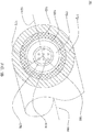
- FIG. 1A illustrates a cross-sectional view of a few mode optical fiber 100, in accordance with various embodiments of the present disclosure.
- the few mode optical fiber 100 is a fiber used for transmitting information as light pulses from one end to another.
- the few mode optical fiber 100 is a thin strand of glass or plastic capable of transmitting optical signals.
- the few mode optical fiber 100 is configured to transmit large amount of information over long distances with relatively low attenuation.
- the few mode optical fiber 100 can be utilized for Space Division Multiplexing Applications.
- the few mode optical fiber 100 is operated in different modes including Lp01 mode and Lp11 mode.
- the few mode optical fiber 100 can be operated in six modes including two degenerate Lp01 modes and four degenerate Lp11 modes.
- the few mode optical fiber is operated in broad range of wavelength between 1460 nm to 1625 nm for both Lp01 mode and Lp11 mode.
- the few mode optical fiber is operated in broad range of wavelength in S,C and L bands.
- a few mode optical fiber is that in which fibers support only few guided modes.
- a two-mode optical fiber (with LP01 and LP11) exhibits 6 different modes considering the degeneracy's.
- the few mode optical fiber 100 may be utilized for other applications. Going further, the few mode optical fiber 100 is dispersion optimized few mode optical fiber. The few mode optical fiber 100 allows the light to travel in more than one mode. The few mode dispersion optimized optical fiber is used for Spacedivision multiplexing applications. In addition, the few mode optical fiber 100 has increased data rate by allowing the light to travel in more than one mode.
- the type of the dispersion which occurs inside the few mode optical fiber is chromatic dispersion.
- the chromatic dispersion is the spreading of the optical signals which results from different speeds of light rays travelling inside the optical fiber 100.
- the chromatic dispersion occurs due to material dispersion and waveguide dispersion.
- the material dispersion occurs due to a change in a refractive index of the optical fiber 100 with an optical frequency. Moreover, the waveguide dispersion occurs due to dependency of mode propagation on wavelength. In an embodiment of the present disclosure, the few mode optical fiber 100 has a pre-determined value of dispersion (provided below in the detailed description).
- the dispersion optimized few mode optical fiber 100 enables controlled dispersion over a range of wavelength.
- the few mode optical fiber 100 exhibits low dispersion in Lp01 mode and Lp11 mode for wavelength range of 1460nm-1625nm.
- the dispersion optimized few mode fiber 100 enables minimization of spatial overlap between the Lp01 mode and Lp11 mode.
- the few mode optical fiber enables near zero spatial overlap between Lp01 mode and Lp11 mode throughout the range of wavelength.
- the dispersion optimized few mode optical fiber 100 enables the dispersion optimization throughout the range of wavelength.
- the range of wavelength corresponds to a range in which the few mode optical fiber 100 is configured to operate.
- the range of wavelength for the present disclosure is 1460 nm - 1625 nm.
- the few mode optical fiber 100 is used for spacedivision multiplexing to increase the data capacity.
- the optical signals is transmitted in different guiding modes of the optical fiber 100. Accordingly, the optical signals are separated at another end.
- the dispersion optimized few mode optical fiber 100 is used for communication purpose. In another embodiment of the present disclosure, the dispersion optimized few mode optical fiber 100 is operated in S, C and L bands.
- the mode field diameter defines a section or area of the few mode optical fiber 100 in which the optical signals travel.
- the theoretical cut-off wavelength is defined as the wavelength above which the given mode cannot propagate.
- each of the plurality of attributes has a specific value or a range of value.
- the few mode optical fiber 100 has a mode field diameter in the range of 7.4 ⁇ m to 8.4 ⁇ m for Lp01 mode at a wavelength of 1550 nm.
- the mode field diameter (MFD) is an expression of distribution of the optical power.
- mode field diameter plays an important role in estimating macro bending losses.
- the few mode optical fiber 100 exhibits bending losses.
- the bend losses correspond to the losses that the optical fiber exhibits when they are bent.
- the bending loss includes macro bending losses and micro bending losses.
- the few mode optical fiber 100 exhibits macro bending loss less than 2.1 dB/turn for 16 mm bending radius at a wavelength of 1625 nm for Lp11 mode.
- the few mode optical fiber cable 100 has an effective area. Effective area determines how much energy the core can carry without causing non-linear type signal losses.
- the effective area of the fundamental mode is a measure of the area over which the energy in the electric field is distributed.
- the few mode optical fiber 100 has an effective area in the range of 40 ⁇ m 2 to 60 ⁇ m 2 for Lp01 mode at a wavelength of 1550 nm.
- the few mode optical fiber 100 has an effective area in the range of 360 ⁇ m 2 to 570 ⁇ m 2 for Lp11 mode at a wavelength of 1550 nm.
- the few mode optical fiber 100 has a differential group delay between Lp01 mode and Lp11 mode.
- the differential group delay is the difference in propagation time between the two eigen modes.
- the differential group delay between Lp01 mode and Lp11 mode is less than 0.2ps/km at a wavelength of 1550 nm.
- the spatial overlap between the Lp01 mode and Lp11 mode is less than 10 -5 .
- the few mode optical fiber 100 has a theoretical cut-off wavelength.
- the theoretical cut-off wavelength refers to the wavelength above which the given mode cannot propagate.
- the theoretical cut-off wavelength for Lp11 mode is in the range of 2280 nm to 2810 nm. In another embodiment of the present disclosure, the theoretical cut-off wavelength for Lp02 mode less than 2500 nm.
- the few mode optical fiber 100 includes a core region 170 and a cladding region.
- the core region 170 is an inner part of the few mode optical fiber 100 and the cladding section is an outer part of the few mode optical fiber 100.
- the core region 170 is defined by a region around a central longitudinal axis 184 of the few mode optical fiber 100 (As shown in the perspective view of the few mode optical fiber in FIG. 1B ).
- the core region 170 is defined by a region around a central longitudinal axis 184 of the few mode optical fiber 100.
- the longitudinal axis 184 passes through the geometrical center 186 of the optical fiber cable 100.
- the refractive index profile determines a relationship between the refractive index of the few mode optical fiber 100 with a radius of the few mode optical fiber 100. Also, the refractive index profile is maintained as per a desired level based on a concentration of chemicals used for the production of the few mode optical fiber 100. In an embodiment of the present disclosure, the production of the few mode optical fiber 100 is carried out after construction of an optical fiber preform.
- the refractive index profile of the few mode optical fiber 100 is determined during the manufacturing of the few mode optical fiber preform.
- the refractive index profile is determined based on a concentration of chemicals used during the manufacturing of the few mode optical fiber preform.
- the chemicals used for the manufacturing of the few mode optical fiber 100 include one or more materials and one or more dopants.
- the one or more materials and the one or more dopants are deposited over a surface of an initial material by performing flame hydrolysis.
- the initial material is a substrate rod or a tube. The deposition is done for achieving a pre-structure of the few mode optical fiber 100.
- the few mode optical fiber 100 is manufactured by performing a specific chemical deposition technique of a plurality of chemical deposition techniques.
- Each of the plurality of chemical deposition techniques performs a chemical vapor deposition over a surface of the initial material by flame hydrolysis or inside the initial material.
- the plurality of chemical deposition techniques includes a modified chemical vapor deposition technique, an outside vapor deposition technique, an axial vapor deposition technique and the like.
- Each of the plurality of chemical deposition techniques ensures a specific refractive index required.
- each of the plurality of chemical deposition techniques manufactures the core region 170 and the cladding region of the few mode optical fiber 100.
- the radius of the few mode optical fiber 100 is maintained under a pre-defined value set.
- the Lp01optical signals in the few mode optical fiber 100 will preferentially propagate in the first annular region 174 which is the central core region of the few mode optical fiber 100. Further, the Lp11 signals in the few mode optical fiber 100 will preferentially propagate in the fifth annular region 182 which is the high index ring region of the few mode optical fiber 100.
- the cladding region is defined by a different refractive index profile.
- the refractive index profile of the core region 170 and the cladding region is shown through a single graph (as shown in the FIG. 2 ).
- the few mode optical fiber 100 includes the core region 170.
- the core region 170 has the refractive index profile (as shown in the FIG. 2 ).
- the few mode optical fiber 100 includes a plurality of regions in the core region 170 of the few mode optical fiber 100. In an embodiment of the present disclosure, the core region 170 of the few mode optical fiber 100 is divided into the plurality of regions.
- Each of the plurality of regions is defined by a corresponding refractive index and a corresponding radius.
- the refractive index of each of the plurality of regions of the core region 170 is different.
- the radius of each of the plurality of regions of the core region 170 is different.
- the refractive index profile of the core region 170 of the few mode optical fiber 100 changes from the geometrical center 186 of the optical fiber 100 to the radius of the core.
- the refractive index of each of the plurality of regions of the core region 170 has a pre-defined range of value (mentioned below in detail).
- the radius of each of the plurality of regions of the core region 170 has a pre-defined range of value (mentioned below in detail).
- the pre-defined range of value of the refractive index is set to obtain controlled dispersion, minimized spatial overlap and bending losses.
- the spatial overlap between the Lp01 mode and Lp11 mode is less than 10 -5 .
- the pre-defined range of value of the refractive index of each of the plurality of regions is set to maintain the dispersion in pre-defined range or value. Further, the pre-defined range of the value of the core radius is optimized to enable the low bending losses. Furthermore, pre-defined range of the value of the core radius is optimized to enable the minimized spatial overlap between the Lp01 and Lp11 modes. In addition, each region of the plurality of regions has the corresponding refractive index value.
- the refractive index of each region of the plurality of regions is fixed over a cross-sectional area of each region.
- the core region 170 has a first annular region 174, a second annular region 176, a third annular region 178, a fourth annular region 180 and a fifth annular region 182.
- the plurality of regions includes the first annular region 174, the second annular region 176, and the third annular region 178.
- the plurality of regions includes the fourth annular region 180 and the fifth annular region 182.
- the first annular region 174, the second annular region 176, the third annular region 178, the fourth annular region 180 and the fifth annular region 182 are concentrically arranged.
- the second annular region 176 surrounds the first annular region 174
- the third annular region 178 surrounds the second annular region 176
- the fourth annular region 180 surrounds the third annular region 178.
- the fifth annular region 182 surrounds the fourth annular region 180.
- the first annular region 174, the second annular region 176, the third annular region 178, the fourth annular region 180 and the fifth annular region 182 is associated with the corresponding refractive index and the corresponding radius.(Mentioned below in detail).
- the first annular region 174 is the central core region.
- the peak shaping parameter alpha ( ⁇ ) of the central core region is in the range of 2.7 to 10.
- the refractive index of the annular regions 174, 176, 178, 180 and 182 is optimized to get different dispersion, minimized spatial overlap and low bending losses.
- the thickness and refractive index of annular regions 174, 176, 178, 180 and 182 is optimized to minimize the spatial overlap between the Lp01 mode and Lp11 mode.
- the refractive index and the radius are optimized based on a change in the concentration of a dopant used.
- the dopant includes germanium dioxide, phosphorous pentoxide, aluminium trioxide and the like.
- the radius of the first annular region 174, the second annular region 176, the third annular region 178, the fourth annular region 180 and the fifth annular region 182 is optimized for the low bending loss. Furthermore, the radius of all the annular regions including 174, 176, 178, 180 and 182 is optimized for minimized spatial overlap and low differential group delay between the modes.
- the first annular region 174 is between the central longitudinal axis 184 of the few mode optical fiber 100 and a first radius r 1 from the central longitudinal axis 184 of the few mode optical fiber 100.
- the first annular region 174 has a first refractive index delta-1.
- the second annular region 176 is between the first radius r 1 and a second radius r 2 from the central longitudinal axis 184 of the few mode optical fiber 100.
- the second annular region 176 has a second refractive index delta-2.
- the third annular region 178 is between the second radius r 2 and a third radius r 3 from the central longitudinal axis 184 of the few mode optical fiber 100.
- the third annular region 178 has a third refractive index delta-3.
- the fourth annular region 180 is between the third radius r 3 and a fourth radius r 4 from the central longitudinal axis 184 of the few mode optical fiber 100.
- the fourth annular region 180 has a fourth refractive index delta-4.
- the fifth annular region 182 is between the fourth radius r 4 and a fifth radius r 5 from the central longitudinal axis 184 of the few mode optical fiber 100.
- the fifth annular region 182 has a fifth refractive index delta-5.
- delta % ⁇ % 100 ⁇ n i 2 ⁇ n cl 2 2 ⁇ n i 2
- the first radius r 1 is in the range of 3.8 microns to 4.2 microns.
- the first refractive index delta-1 is in the range of 0.42 to 0.70.
- the second radius r 2 is in the range of 4.8 microns to 5.2 microns.
- the second refractive index delta-2 is zero.
- the third radius r 3 is in the range of 8.2 microns to 8.7 microns.
- the third refractive index delta-3 is in the range of 0.4 to 0.58.
- the fourth radius r 4 is in the range of 8.3 microns to 9.9 microns.
- the fourth refractive index delta-4 is zero.
- the fifth radius r 5 is in the range of 10.9 microns to 12.6 microns.
- the fifth refractive index delta-5 is in the range of 0.41 to 0.62.
- the first annular region 174 is the central core region
- the second annular region 176 is the buffer region
- the third annular region 178 is the trench region.
- the trench region is a downdopant region in the optical fiber 100.
- Downdopant is a type of dopant which has the tendency to decrease the refractive index of glass with respect to pure.
- the fourth annular region 180 is the buffer region and the fifth annular region 182 is the high index ring region.
- the central core region and the high Index Ring region is an updopant region in the optical fiber cable 100. Updopant is a type of dopant which has the tendency to increase the refractive index of glass with respect to pure.
- the buffer region is undopant region and consist pure silica.
- the few mode optical fiber 100 includes a cladding.
- the cladding surrounds the core region 170.
- the cladding is concentrically arranged around the core region 170.
- the cladding covers the core region 170.
- the cladding is defined by a specific refractive index and a specific radius. In an embodiment of the present disclosure, the refractive index and the radius of the cladding is optimized for achieving the pre-defined value of the dispersion.
- the cladding is a sixth annular region 172 of the optical fiber 100.
- the sixth annular region 172 is between the fifth radius r 5 and the sixth radius r 6 .
- the sixth annular region 172 concentrically surrounds the fifth annular region 182.
- the sixth radius r 6 is 62.5 microns.
- the sixth refractive index delta-6 is zero.
- the value of the sixth refractive index delta-6 is constant throughout a cross-sectional area of the sixth annular region 172 (as shown in the FIG. 2 ).
- the sixth radius r 6 of the sixth annular region 178 is fixed.
- the value of the sixth refractive index delta-6 and the sixth radius r 6 is optimized for achieving the pre-defined value of the dispersion, the intermodal crosstalk and the bending losses.
- FIG. 2 illustrates a refractive index profile 200 of the few mode optical fiber 100, in accordance with various embodiments of the present disclosure. It may be noted that to explain a graphical appearance of the refractive index profile 200, references will be made to the structural elements of the few mode optical fiber 100.
- the refractive index profile 200 illustrates a relationship between the refractive index of the few mode optical fiber 100 and the radius of the few mode optical fiber 100 (as stated above in the detailed description of the FIG. 1A ). In an embodiment of the present disclosure, the refractive index profile 200 shows the change in the refractive index of the few mode optical fiber 100 with the radius of the few mode optical fiber 100.
- the first annular region 174 has high index region.
- the first annular region 174 is the central core region.
- the second annular region 176 is the buffer region.
- the third annular region 178 is the trench region.
- the fourth annular region 180 is the buffer region.
- the fifth annular region 182 is the high index ring region.
- the sixth annular region 172 is the cladding region.
- the first radius r 1 is in the range of 3.8 microns to 4.2 microns.
- the first refractive index delta-1 is in the range of 0.42 to 0.70.
- the second radius r 2 is in the range of 4.8 microns to 5.2 microns.
- the second refractive index delta-2 is zero.
- the third radius r 3 is in the range of 8.2 microns to 8.7 microns.
- the third refractive index delta-3 is in the range of 0.4 to 0.58.
- the fourth radius r 4 is in the range of 8.3 microns to 9.9 microns.
- the fourth refractive index delta-4 is zero.
- the fifth radius r 5 is in the range of 10.9 microns to 12.6 microns.
- the fifth refractive index delta-5 is in the range of 0.41 to 0.62.
- the sixth radius r 6 is 62.5 microns.
- the sixth refractive index delta-6 is zero.
- the peak shaping parameter alpha ( ⁇ ) of the central core region is in the range of 2.7 to 10.
- the few mode optical fiber 100 is operated in the wavelength range of 1460 nm to 1625 nm in Lp01 mode and Lp11 mode.
- the few mode optical fiber is operated in six modes. The six modes include two degenerate Lp01 modes and four degenerate Lp11 modes.
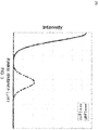
- FIG. 3 illustrates an intensity-radial distance profile 300 for Lp01 mode and Lp11 mode, in accordance with an embodiment of the present disclosure.
- the spatial overlap between the intensity profiles of Lp01 mode and Lp11 mode is less than 10 -5 .
- the marching line in the curve represents the Lp11 mode whereas the dark line in the curve represents the Lp01 mode.
- the radius r 1 of the first annular region 174 is 4.15 microns.
- the refractive index delta-1 of the first annular region 174 is 0.54.
- the alpha ( ⁇ ) of the first annular region 174 which is the central core region is 2.7.
- the radius r 2 of the second annular region 176 is 5.15 microns.
- the refractive index delta-2 of the second annular region 176 is zero.
- the radius r 3 of the third annular region 178 is 8.65 microns.
- the refractive index delta-3 of the third annular region 178 is 0.41.
- the radius r 4 of the fourth annular region 180 is 8.85 microns.
- the refractive index delta-4 of the fourth annular region 180 is zero.
- the radius r 5 of the fifth annular region 182 is 11.75 microns.
- the refractive index delta-5 of the fifth annular region 182 is 0.6.
- the radius r 6 of the sixth annular region 172 is 62.5 microns.
- the refractive index delta-6 of the sixth annular region 172 is zero.
- the dispersion is 4.94 Ps/nm/km for Lp01 mode at a wavelength of 1460 nm.
- the dispersion is 1.67 Ps/nm/km for Lp11 mode at a wavelength of 1460nm.
- the dispersion is 4.95 Ps/nm/km for Lp01 mode at a wavelength of 1530 nm.
- the dispersion is 6.6 Ps/nm/km for Lp11 mode at a wavelength of 1530 nm.
- the dispersion is 4.78 Ps/nm/km for Lp01 mode at a wavelength of 1550 nm.
- the dispersion is 7.96 Ps/nm/km at Lp11 mode at a wavelength of 1550 nm.
- the dispersion is 4.55 Ps/nm/km for Lp01 mode at a wavelength of 1565 nm.
- the dispersion is 8.96 Ps.nm/km for Lp11 mode at a wavelength of 1565 nm.
- the dispersion is 3.95 Ps/nm/km for Lp01 mode at a wavelength of 1625 nm.
- the dispersion is 12.64 Ps/nm/km for Lp11 mode at a wavelength of 1625 nm.
- the mode field diameter of the optical fiber 100 for Lp01 mode is 8.2 ⁇ m at a wavelength of 1550 nm.
- the spatial overlap between Lp01 mode and Lp11 mode in the optical fiber 100 is less than 10 -5 .
- the macrobend loss for Lp11 mode in the optical fiber 100 is 1.492 dB/turn for 16 mm bending radius at a wavelength of 1625 nm.
- the effective area of the optical fiber 100 is 55 ⁇ m 2 for Lp01 mode at a wavelength of 1550 nm.
- the effective area of the optical fiber 100 is 390 ⁇ m 2 for Lp11 mode at a wavelength of 1550 nm.
- the theoretical cut-off wavelength for Lp11 mode is 2797 nm.
- the theoretical cut-off wavelength for Lp02 mode is 2165 nm.
- the differential group delay between Lp01 mode and Lp11 mode at a wavelength of 1550 nm is 0.004 ps/km.
- the radius r 1 of the first annular region 174 is 4.15 microns.
- the refractive index delta-1 of the first annular region 174 is 0.56.
- the alpha ( ⁇ ) of the first annular region 174 which is the central core region is 8.
- the radius r 2 of the second annular region 176 is 5.15 microns.
- the refractive index delta-2 of the second annular region 176 is zero.
- the radius r 3 of the third annular region 178 is 8.65 microns.
- the refractive index delta-3 of the third annular region 178 is 0.40.
- the radius r 4 of the fourth annular region 180 is 8.85 microns.
- the refractive index delta-4 of the fourth annular region 180 is zero.
- the radius r 5 of the fifth annular region 182 is 11.75 microns.
- the refractive index delta-5 of the fifth annular region 182 is 0.59.
- the radius r 6 of the sixth annular region 172 is 62.5 microns.
- the refractive index delta-6 of the sixth annular region 172 is zero.
- the dispersion is 13.7 Ps/nm/km for Lp01 mode at a wavelength of 1460 nm.
- the dispersion is 1.62 Ps/nm/km for Lp11 mode at a wavelength of 1460nm.
- the dispersion is 17.48 Ps/nm/km for Lp01 mode at a wavelength of 1530 nm.
- the dispersion is 6.58 Ps/nm/km for Lp11 mode at a wavelength of 1530 nm.
- the dispersion is 18.42 Ps/nm/km for Lp01 mode at a wavelength of 1550 nm.
- the dispersion is 7.98 Ps/nm/km at Lp11 mode at a wavelength of 1550 nm.
- the dispersion is 19.09 Ps/nm/km for Lp01 mode at a wavelength of 1565 nm.
- the dispersion is 8.98 Ps.nm/km for Lp11 mode at a wavelength of 1565 nm.
- the dispersion is 21.31 Ps/nm/km for Lp01 mode at a wavelength of 1625 nm.
- the dispersion is 12.95 Ps/nm/km for Lp11 mode at a wavelength of 1625 nm.
- the mode field diameter of the optical fiber 100 for Lp01 mode is 7.8 ⁇ m at a wavelength of 1550 nm.
- the spatial overlap between Lp01 mode and Lp11 mode in the optical fiber 100 is less than 10 -5 .
- the macrobend loss for Lp11 mode in the optical fiber 100 is 1.49 dB/turn for 16 mm bending radius at a wavelength of 1625 nm.
- the effective area of the optical fiber 100 is 49 ( ⁇ m 2 for Lp01 mode at a wavelength of 1550 nm.
- the effective area of the optical fiber 100 is 392 ( ⁇ m 2 for Lp11 mode at a wavelength of 1550 nm.
- the theoretical cut-off wavelength for Lp11 mode is 2738 nm.
- the theoretical cut-off wavelength for Lp02 mode is 2380 nm.
- the differential group delay between Lp01 mode and Lp11 mode at a wavelength of 1550 nm is 0.010 ps/km.
- the radius r 1 of the first annular region 174 is 4.10 microns.
- the refractive index delta-1 of the first annular region 174 is 0.49.
- the alpha ( ⁇ ) of the first annular region 174 which is the central core region is 10.
- the radius r 2 of the second annular region 176 is 4.9 microns.
- the refractive index delta-2 of the second annular region 176 is zero.
- the radius r 3 of the third annular region 178 is 8.3 microns.
- the refractive index delta-3 of the third annular region 178 is 0.52.
- the radius r 4 of the fourth annular region 180 is 8.3 microns.
- the refractive index delta-4 of the fourth annular region 180 is zero.
- the radius r 5 of the fifth annular region 182 is 10.9 microns.
- the refractive index delta-5 of the fifth annular region 182 is 0.62.
- the radius r 6 of the sixth annular region 172 is 62.5 microns.
- the refractive index delta-6 of the sixth annular region 172 is zero.
- the dispersion is 12.69 Ps/nm/km for Lp01 mode at a wavelength of 1460 nm.
- the dispersion is 0.37 Ps/nm/km for Lp11 mode at a wavelength of 1460nm.
- the dispersion is 15.35 Ps/nm/km for Lp01 mode at a wavelength of 1530 nm.
- the dispersion is 4.57 Ps/nm/km for Lp11 mode at a wavelength of 1530 nm.
- the dispersion is 16.1 Ps/nm/km for Lp01 mode at a wavelength of 1550 nm.
- the dispersion is 5.85 Ps/nm/km at Lp11 mode at a wavelength of 1550 nm.
- the dispersion is 16.3 Ps/nm/km for Lp01 mode at a wavelength of 1565 nm.
- the dispersion is 6.84 Ps.nm/km for Lp11 mode at a wavelength of 1565 nm.
- the dispersion is 18.1 Ps/nm/km for Lp01 mode at a wavelength of 1625 nm.
- the dispersion is 10.75 Ps/nm/km for Lp11 mode at a wavelength of 1625 nm.
- the mode field diameter of the optical fiber 100 for Lp01 mode is 8 ⁇ m at a wavelength of 1550 nm.
- the spatial overlap between Lp01 mode and Lp11 mode in the optical fiber 100 is less than 10 -5 .
- the macrobend loss for Lp11 mode in the optical fiber 100 is 1.47 dB/turn for 16mm bending radius at a wavelength of 1625 nm.
- the effective area of the optical fiber 100 is 53 ⁇ m 2 for Lp01 mode at a wavelength of 1550 nm.
- the effective area of the optical fiber 100 is 368 ⁇ m 2 for Lp11 mode at a wavelength of 1550 nm.
- the theoretical cut-off wavelength for Lp11 mode is 2645 nm.
- the theoretical cut-off wavelength for Lp02 mode is 2241 nm.
- the differential group delay between Lp01 mode and Lp11 mode at a wavelength of 1550 nm is 0.005 ps/km.
- the radius r 1 of the first annular region 174 is 3.8 microns.
- the refractive index delta-1 of the first annular region 174 is 0.70.
- the alpha ( ⁇ ) of the first annular region 174 which is the central core region is 10.
- the radius r 2 of the second annular region 176 is 4.8 microns.
- the refractive index delta-2 of the second annular region 176 is zero.
- the radius r 3 of the third annular region 178 is 8.4 microns.
- the refractive index delta-3 of the third annular region 178 is 0.54.
- the radius r 4 of the fourth annular region 180 is 9.9 microns.
- the refractive index delta-4 of the fourth annular region 180 is zero.
- the radius r 5 of the fifth annular region 182 is 12.6 microns.
- the refractive index delta-5 of the fifth annular region 182 is 0.62.
- the radius r 6 of the sixth annular region 172 is 62.5 microns.
- the refractive index delta-6 of the sixth annular region 172 is zero.
- the dispersion is 15.98 Ps/nm/km for Lp01 mode at a wavelength of 1460 nm.
- the dispersion is 3.64 Ps/nm/km for Lp11 mode at a wavelength of 1460nm.
- the dispersion is 20.39 Ps/nm/km for Lp01 mode at a wavelength of 1530 nm.
- the dispersion is 8.63 Ps/nm/km for Lp11 mode at a wavelength of 1530 nm.
- the dispersion is 21.62 Ps/nm/km for Lp01 mode at a wavelength of 1550 nm.
- the dispersion is 10.01 Ps/nm/km at Lp11 mode at a wavelength of 1550 nm.
- the dispersion is 22.49 Ps/nm/km for Lp01 mode at a wavelength of 1565 nm.
- the dispersion is 11.03 Ps.nm/km for Lp11 mode at a wavelength of 1565 nm.
- the dispersion is 25.51 Ps/nm/km for Lp01 mode at a wavelength of 1625 nm.
- the dispersion is 14.75 Ps/nm/km for Lp11 mode at a wavelength of 1625 nm.
- the mode field diameter of the optical fiber 100 for Lp01 mode is 7.4 ⁇ m at a wavelength of 1550 nm.
- the spatial overlap between Lp01 mode and Lp11 mode in the optical fiber 100 is less than 10 -5 .
- the macrobend loss for Lp11 mode in the optical fiber 100 is 1.3 dB/turn for 16 mm bending radius at a wavelength of 1625 nm.
- the effective area of the optical fiber 100 is 43 ⁇ m 2 for Lp01 mode at a wavelength of 1550 nm.
- the effective area of the optical fiber 100 is 425 ⁇ m 2 for Lp11 mode at a wavelength of 1550 nm.
- the theoretical cut-off wavelength for Lp11 mode is 2810 nm.
- the theoretical cut-off wavelength for Lp02 mode is 2500 nm.
- the differential group delay between Lp01 mode and Lp11 mode at a wavelength of 1550 nm is 0.020 ps/km.
- the radius r 1 of the first annular region 174 is 3.8 microns.
- the refractive index delta-1 of the first annular region 174 is 0.42.
- the alpha ( ⁇ ) of the first annular region 174 which is the central corc region is 10.
- the radius r 2 of the second annular region 176 is 5 microns.
- the refractive index delta-2 of the second annular region 176 is zero.
- the radius r 3 of the third annular region 178 is 8.2 microns.
- the refractive index delta-3 of the third annular region 178 is 0.58.
- the radius r 4 of the fourth annular region 180 is 9.7 microns.
- the refractive index delta-4 of the fourth annular region 180 is zero.
- the radius r 5 of the fifth annular region 182 is 12.3 microns.
- the refractive index delta-5 of the fifth annular region 182 is 0.41.
- the radius r 6 of the sixth annular region 172 is 62.5 microns.
- the refractive index delta-6 of the sixth annular region 172 is zero.
- the dispersion is 12.3 Ps/nm/km for Lp01 mode at a wavelength of 1460 nm.
- the dispersion is 5.64 Ps/nm/km for Lp11 mode at a wavelength of 1460nm.
- the dispersion is 13.9 Ps/nm/km for Lp01 mode at a wavelength of 1530 nm.
- the dispersion is 10.4 Ps/nm/km for Lp11 mode at a wavelength of 1530 nm.
- the dispersion is 13.84 Ps/nm/km for Lp01 mode at a wavelength of 1550 nm.
- the dispersion is 11.77 Ps/nm/km at Lp11 mode at a wavelength of 1550 nm.
- the dispersion is 13.6 Ps/nm/km for Lp01 mode at a wavelength of 1565 nm.
- the dispersion is 12.69 Ps.nm/km for Lp11 mode at a wavelength of 1565 nm.
- the dispersion is 10.86 Ps/nm/km for Lp01 mode at a wavelength of 1625 nm.
- the dispersion is 16.25 Ps/nm/km for Lp11 mode at a wavelength of 1625 nm.
- the mode field diameter of the optical fiber 100 for Lp01 mode is 8 ⁇ m at a wavelength of 1550 nm.
- the spatial overlap between Lp01 mode and Lp11 mode in the optical fiber 100 is less than 10 -5 .
- the macrobend loss for Lp11 mode in the optical fiber 100 is 2.1 dB/turn for 16mm bending radius at a wavelength of 1625 nm.
- the effective area of the optical fiber 100 is 51 ⁇ m 2 for Lp01 mode at a wavelength of 1550 nm.
- the effective area of the optical fiber 100 is 570 ⁇ m 2 for Lp11 mode at a wavelength of 1550 nm.
- the theoretical cut-off wavelength for Lp11 mode is 2281 nm.
- the theoretical cut-off wavelength for Lp02 mode is 1950 nm.
- the differential group delay between Lp01 mode and Lp11 mode at a wavelength of 1550 nm is 0.012 ps/km.
- the present disclosure provides numerous advantages over the prior art.
- the present disclosure provides the few mode optical fiber with controlled dispersion, minimized spatial overlap and low bending losses.
- the few mode optical fiber is operated in Lp01 mode and Lp11 mode.
- the few mode optical fiber is operated in six modes including two degenerate Lp01 modes and four Lp11 modes.
- the present disclosure provides spatial overlap less than 10 -5 between Lp01 mode and Lp11 mode throughout the range of wavelength between 1460 nm to 1625 nm.
Landscapes
- Physics & Mathematics (AREA)
- General Physics & Mathematics (AREA)
- Optics & Photonics (AREA)
- Chemical & Material Sciences (AREA)
- Dispersion Chemistry (AREA)
- Engineering & Computer Science (AREA)
- Computer Networks & Wireless Communication (AREA)
- Signal Processing (AREA)
- Optical Modulation, Optical Deflection, Nonlinear Optics, Optical Demodulation, Optical Logic Elements (AREA)
- Lasers (AREA)
- Manufacture, Treatment Of Glass Fibers (AREA)
Abstract
Description
- The present disclosure relates to the field of optical fiber transmission. More particularly, the present disclosure relates to dispersion controlled few mode optical fiber with minimal spatial overlap between Lp01 and Lp11 guiding modes. The few mode optical fiber as described herein is suitable for space division multiplexing (SDM) applications.
- Over the last few years, optical fibers have secured a very important role in communication networks throughout the world. The present day coherent communication systems use the dense wavelength division multiplexing techniques to transfer the data. Several coherent modulation techniques such as OOK or QPSK with single mode fibers have been used to increase the data rate capacity of the communication system by taking almost all the freedoms available in modulation schemes. The telecommunication industry is continuously striving for the designs to meet the exponential increase in the data rate capacity demand. The ongoing research suggests that the few mode fiber which can allow the light to travel more than one mode with spatial division multiplexing scheme scan be a potential solution to increase the data rate by allowing the signal to transmit in more than one mode. Typically, the performance of these optical fibers is determined based on dispersion, intermodal crosstalk occurring due to spatial overlap between guiding modes and bending losses over a broad range of wavelength. In general, the dispersion, spatial overlap and bending losses are optimized based on a refractive index profile. The refractive index profile defines the properties of a core section and a cladding section. Also, the refractive index profile illustrates a relationship between the refractive index of the optical fiber with a radius of the optical fiber. Further, this profile is determined based on a concentration of dopants and materials used during manufacturing. Furthermore, the dispersion, spatial overlap between modes and bending losses are controlled by varying the thickness of each region of the optical fiber.
- Currently available profiles of few mode fibers are not optimized for dispersion and spatial overlap between the Lp01 mode and Lp11 mode to use in broad band SDM applications in S, C and L bands. This results in intermodal crosstalk between the guiding modes.
- In light of the above stated discussion, there is a dire need for a few mode optical fiber with dispersion control and minimized spatial overlap for low intermodal crosstalk between the modes while being suitable for SDM systems in long haul communications.
- According to a first aspect there is provided a few mode optical fiber comprising: a core region defined by a region around a central longitudinal axis of the few mode optical fiber, the core region comprising: a first annular region, wherein the first annular region is between the central longitudinal axis and a first radius r1, wherein the first annular region has a first refractive index delta-1; a second annular region, wherein the second annular region is between the first radius r1 and a second radius r2, wherein the second annular region has a second refractive index delta-2; a third annular region, wherein the third annular region is between the second radius r2 and a third radius r3, wherein the third annular region has a third refractive index delta-3; a fourth annular region, wherein the fourth annular region is between the third radius r3 and a fourth radius r4, wherein the fourth annular region has a fourth refractive index Δ4, wherein the fourth radius r4 is in a range of 8.3 microns to 9.9 microns and the fourth refractive index delta-4 is approximately zero; a fifth annular region, wherein the fifth annular region is between the fourth radius r4 and a fifth radius r5, wherein the fifth annular region has a fifth refractive index delta-5, wherein the fifth radius r5 is in a range of 10.9 microns to 12.6 microns and the fifth refractive index delta-5 is in a range of 0.41 to 0.62; and a cladding region, wherein the cladding region is a sixth annular region between the fifth radius r5 and a sixth radius r6, wherein the sixth annular region has a sixth refractive index delta-6, wherein the sixth radius r6 is 62.5 microns and the sixth refractive index delta-6 is approximately zero, wherein the first annular region, the second annular region, the third annular region, the fourth annular region, the fifth annular region and the sixth annular region are concentrically arranged about the central longitudinal axis, and wherein the few mode optical fiber has a spatial overlap between the Lp01 mode and Lp11 mode of less than 10-5.
- According to a second aspect there is provided a few mode optical fiber comprising: a core region defined by a region around a central longitudinal axis of the few mode optical fiber, the core region comprising: a plurality of annular regions, wherein the plurality of annular regions comprising: a fourth annular region, wherein the fourth annular region is between a third radius r3 and a fourth radius r4, wherein the fourth annular region has a fourth refractive index Δ4, wherein the fourth radius r4 is in a range of 8.3 microns to 9.9 microns and the fourth refractive index delta-4 is approximately zero; a fifth annular region, wherein the fifth annular region is between the fourth radius r4 and a fifth radius r5, wherein the fifth annular region has a fifth refractive index delta-5, wherein the fifth radius r5 is in a range of 10.9 microns to 12.6 microns and the fifth refractive index delta-5 is in a range of 0.41 to 0.62; and a cladding region, wherein the cladding region is a sixth annular region between the fifth radius r5 and a sixth radius r6, wherein the sixth annular region has a sixth refractive index delta-6, wherein the fourth annular region, the fifth annular region and the sixth annular region are concentrically arranged about the central longitudinal axis, wherein the few mode optical fiber has a spatial overlap between the Lp01 mode and Lp11 mode of less than 10-5.
- The first radius r1 may be in a range of 3.8 microns to 4.2 microns. The first refractive index delta-1 may be in a range of 0.42 to 0.70. The second radius r2 may be in a range of 4.8 microns to 5.2 microns. The second refractive index delta-2 may be approximately zero. The third radius r3 may be in a range of 8.2 microns to 8.7 microns. The third refractive index delta-3 may be in a range of 0.4 to 0.58.
- The first annular region may have an alpha profile. The alpha profile may be defined by a peak shaping parameter alpha. The peak shaping parameter alpha may be in a range of 2.7 to 10.
- The few mode optical fiber may have a mode field diameter in a range of 7.4 µm to 8.2 µm for Lp01 mode at a wavelength of 1550 nm. The few mode optical fiber may have an effective area in a range of 43 µm2 to 55 µm2 for Lp01 mode at a wavelength of 1550 nm. The few mode optical fiber may have an effective area in a range of 368 µm2 to 570 µm2 for Lp11 mode at a wavelength of 1550 nm. The few mode optical fiber may have a theoretical cut-off wavelength in a range of 2281 nm to 2810 nm for Lp11 mode. The few mode optical fiber may have a theoretical cut-off wavelength in a range of 1950 nm to 2500 nm for Lp02 mode.
- The few mode optical fiber may have a differential group delay between Lp01 mode and Lp11 mode of less than 0.2 ps/km at a wavelength of 1550 nm.
- The few mode optical fiber may have a dispersion in a range of 4 Ps/nm/km to 16 Ps/nm/km for Lp01 mode at a wavelength of 1460 nm. The few mode optical fiber may have a dispersion in a range of -0.3 ps/nm/km to 6 Ps/nm/km for Lp11 mode at a wavelength of 1460 nm. The few mode optical fiber may have a dispersion in a range of 4.1 Ps/nm/km to 21 Ps/nm/km for Lp01 mode at a wavelength of 1530 nm. The few mode optical fiber may have a dispersion in a range of 4.5 Ps/nm/km to 11 Ps/nm/km for Lp11 mode at a wavelength of 1530 nm. The few mode optical fiber may have a dispersion in a range of 4 Ps/nm/km to 22 Ps/nm/km for Lp01 mode at a wavelength of 1550 nm. The few mode optical fiber may have a dispersion in a range of 5.8 Ps/nm/km to 12 Ps/nm/km for Lp11 mode at a wavelength of 1550 nm. The few mode optical fiber may have a dispersion in a range of 4.5 Ps/nm/km to 23 Ps/nm/km for Lp01 mode at a wavelength of 1565 nm. The few mode optical fiber may have a dispersion in a range of 6.8 Ps/nm/km to 13 Ps/nm/km for Lp11 mode at a wavelength of 1565 nm. The few mode optical fiber may have a dispersion in a range of 3.9 Ps/nm/km to 26 Ps/nm/km for Lp01 mode at a wavelength of 1625 nm. The few mode optical fiber may have a dispersion in a range of 10 Ps/nm/km to 17 Ps/nm/km for Lp11 mode at a wavelength of 1625 nm.
- The few mode optical fiber may have a macrobending loss of less than 2.1 dB/turn for 16 mm bending radius at a wavelength of 1625 nm for Lp11 mode.
- The plurality of annular regions may further comprise the following features. A first annular region. The first annular region may be between the central longitudinal axis and a first radius r1. The first annular region may have a first refractive index delta-1. A second annular region. The second annular region may be between the first radius r1 and a second radius r2. The second annular region may have a second refractive index delta-2. A third annular region. The third annular region may be between the second radius r2 and a third radius r3. The third annular region may have a third refractive index delta-3.
- According to one embodiment, a few mode optical fiber is provided. The optical fiber includes a core region. A core region defined by a region around a central longitudinal axis of the few mode optical fiber. In addition, the core region has a first annular region. The first annular region is between the central longitudinal axis and a first radius r1 from the central longitudinal axis of the few mode optical fiber. Moreover, the core region has a second annular region. The second annular region is between the first radius r1 and a second radius r2 from the central longitudinal axis of the few mode optical fiber. Further, the core has a third annular region. The third annular region is between the second radius r2 to a third radius r3 from the central longitudinal axis of the few mode optical fiber. Furthermore, the core has a fourth annular region. The fourth annular region is between the third radius r3 and a fourth radius r4 from the central longitudinal axis of the few mode optical fiber. Furthermore, the core has a fifth annular region. The fifth annular region is between the fourth radius r4 and a fifth radius r5 from the central longitudinal axis of the few mode optical fiber. The first annular region, the second annular region, the third annular region, the fourth annular region and the fifth annular region are concentrically arranged. In addition, the few mode optical fiber includes a cladding. The cladding is a sixth annular region. The sixth annular region is between a fifth radius r5 and a sixth radius r6 from the central longitudinal axis of the few mode optical fiber. The sixth annular region has a sixth refractive index delta-6. In addition, the first annular region has a first refractive index delta-1. Moreover, the second annular region has a second refractive index delta-2. Further, the third annular region has a third refractive index delta-3. Furthermore, the fourth annular region has a fourth refractive index delta-4. Furthermore, the fifth annular region has a fifth refractive index delta-5. The first annular region, the second annular region, the third region, the fourth region, the fifth region and the sixth annular region are concentrically arranged about the central longitudinal axis. The fourth radius r4 is in the range of 8.3 microns to 9.9 microns. The fourth refractive index delta-4 is zero. The fifth radius r5 is in the range of 10.9 microns to 12.6 microns. The fifth refractive index delta-5 is in the range of 0.41 to 0.62. The sixth radius r6 is 62.5 microns. The sixth refractive index delta-6 is zero. The spatial overlap between the Lp01 mode and Lp11 mode is less than 10-5.
- According to another embodiment, a few mode optical fiber is provided. The optical fiber includes a core region. A core region defined by a region around a central longitudinal axis of the few mode optical fiber. The core region includes plurality of annular regions. The core has a fourth annular region. The fourth annular region is between the third radius r3 and a fourth radius r4 from the central longitudinal axis of the few mode optical fiber. Further, the core has a fifth annular region. The fifth annular region is between the fourth radius r4 and a fifth radius r5 from the central longitudinal axis of the few mode optical fiber. In addition, the few mode optical fiber includes a cladding. The cladding is a sixth annular region. The sixth annular region is between a fifth radius r5 and a sixth radius r6 from the central longitudinal axis of the few mode optical fiber. The sixth annular region has a sixth refractive index delta-6. The sixth annular region concentrically surrounds the fifth annular region. The fourth annular region has a fourth refractive index delta-4. Further, the fifth annular region has a fifth refractive index delta-5. The fourth radius r4 is in the range of 8.3 microns to 9.9 microns. The fourth refractive index delta-4 is zero. The fifth radius r5 is in the range of 10.9 microns to 12.6 microns. The fifth refractive index delta-5 is in the range of 0.41 to 0.62. The sixth radius r6 is 62.5 microns. The sixth refractive index delta-6 is zero. The fourth annular region, the fifth annular region and the sixth annular region are concentrically arranged about the central longitudinal axis. The few mode optical fiber has a spatial overlap between the Lp01 mode and Lp11 mode of less than 10-5.
- According to yet another embodiment, a few mode optical fiber is provided. The optical fiber includes a core region. A core region defined by a region around a central longitudinal axis of the few mode optical fiber. In addition, the core region has a first annular region. The first annular region is between the central longitudinal axis and a first radius r1 from the central longitudinal axis of the few mode optical fiber. Moreover, the core region has a second annular region. The second annular region is between the first radius r1 and a second radius r2 from the central longitudinal axis of the few mode optical fiber. Further, the core has a third annular region. The third annular region is between the second radius r2 to a third radius r3 from the central longitudinal axis of the few mode optical fiber. Furthermore, the core has a fourth annular region. The fourth annular region is between the third radius r3 and a fourth radius r4 from the central longitudinal axis of the few mode optical fiber. Furthermore, the core has a fifth annular region. The fifth annular region is between the fourth radius r4 and a fifth radius r5 from the central longitudinal axis of the few mode optical fiber. The first annular region, the second annular region, the third annular region, the fourth annular region and the fifth annular region are concentrically arranged. In addition, the few mode optical fiber includes a cladding. The cladding is a sixth annular region. The optical fiber has a sixth annular region. The sixth annular region is between a fifth radius r5 and a sixth radius r6 from the central longitudinal axis of the few mode optical fiber. The sixth annular region is the cladding region. The sixth annular region has a sixth refractive index delta-6. The sixth annular region concentrically surrounds the fifth annular region. In addition, the first annular region has a first refractive index delta-1. Moreover, the second annular region has a second refractive index delta-2. Further, the third annular region has a third refractive index delta-3. Furthermore, the fourth annular region has a fourth refractive index delta-4. Furthermore, the fifth annular region has a fifth refractive index delta-5. The first radius r1 is in the range of 3.8 microns to 4.2 microns. The first refractive index delta-1 is in the range of 0.42 to 0.70. The second radius r2 is in the range of 4.8 microns to 5.2 microns. The second refractive index delta-2 is zero. The third radius r3 is in the range of 8.2 microns to 8.7 microns. The third refractive index delta-3 is in the range of 0.4 to 0.58. The fourth radius r4 is in the range of 8.3 microns to 9.9 microns. The fourth refractive index delta-4 is zero. The fifth radius r5 is in the range of 10.9 microns to 12.6 microns. The fifth refractive index delta-5 is in the range of 0.41 to 0.62. The sixth radius r6 is 62.5 microns. The sixth refractive index delta-6 is zero. The spatial overlap between the Lp01 mode and Lp11 mode is less than 10-5. The first annular region is the central core region having an alpha profile. A peak shaping parameter alpha (α) is in a range of 2.7 to 10.
- According to an embodiment a few mode optical fiber comprising: a core region defined by a region around a central longitudinal axis of the few mode optical fiber, the core region comprising: a first annular region, wherein the first annular region is between the central longitudinal axis and a first radius r1, wherein the first annular region has a first refractive index delta-1, wherein the first radius r1 is in a range of 3.8 microns to 4.2 microns and the first refractive index delta-1 is in a range of 0.42 to 0.70; a second annular region, wherein the second annular region is between the first radius r1 and a second radius r2, wherein the second annular region has a second refractive index delta-2, wherein the second radius r2 is in a range of 4.8 microns to 5.2 microns and the second refractive index delta-2 is approximately zero; a third annular region, wherein the third annular region is between the second radius r2 and a third radius r3, wherein the third annular region has a third refractive index delta-3, wherein the third radius r3 is in a range of 8.2 microns to 8.7 microns and the third refractive index delta-3 is in a range of 0.4 to 0.58; a fourth annular region, wherein the fourth annular region is between the third radius r3 and a fourth radius r4, wherein the fourth annular region has a fourth refractive index Δ4, wherein the fourth radius r4 is in a range of 8.3 microns to 9.9 microns and the fourth refractive index delta-4 is approximately zero; a fifth annular region, wherein the fifth annular region is between the fourth radius r4 and a fifth radius r5, wherein the fifth annular region has a fifth refractive index delta-5, wherein the fifth radius r5 is in a range of 10.9 microns to 12.6 microns and the fifth refractive index delta-5 is in a range of 0.41 to 0.62; and a cladding region, wherein the cladding region is a sixth annular region between the fifth radius r5 and a sixth radius r6, wherein the sixth annular region has a sixth refractive index delta-6, wherein the sixth radius r6 is 62.5 microns and the sixth refractive index delta-6 is approximately zero, wherein the first annular region, the second annular region, the third annular region, the fourth annular region, the fifth annular region and the sixth annular region are concentrically arranged about the central longitudinal axis, and wherein the few mode optical fiber has a spatial overlap between the Lp01 mode and Lp11 mode of less than 10-5, and wherein the first annular region has an alpha profile, wherein the alpha profile is defined by a peak shaping parameter alpha, wherein the peak shaping parameter alpha is in a range of 2.7 to 10.
- The summary above, as well as the following detailed description of illustrative embodiments, is better understood when read in conjunction with the appended drawings. For the purpose of illustrating the present disclosure, exemplary constructions of the disclosure are shown in the drawings. However, the present disclosure is not limited to specific methods and instrumentalities disclosed herein. Moreover, those in the art will understand that the drawings are not to scale. Wherever possible, like elements have been indicated by identical numbers.
- Embodiments of the present disclosure will now be described, by way of example only, with reference to the following diagrams wherein:
-
FIG. 1A illustrates a cross-sectional view of a few mode optical fiber, in accordance with various embodiments of the present disclosure; -
FIG. 1B illustrates a perspective view of a few mode optical fiber, in accordance with various embodiments of the present disclosure; -
FIG. 2 illustrates a refractive index profile of the few mode optical fiber, in accordance with various embodiments of the present disclosure; and -
FIG. 3 illustrates a normalized intensity-radial distance profile for Lp01 mode and Lp11 mode, in accordance with an embodiment of the present disclosure. - In the accompanying drawings, an underlined number is employed to represent an item over which the underlined number is positioned or an item to which the underlined number is adjacent. A non-underlined number relates to an item identified by a line linking the non-underlined number to the item. When a number is non-underlined and accompanied by an associated arrow, the non-underlined number is used to identify a general item at which the arrow is pointing.
- The following detailed description illustrates embodiments of the present disclosure and ways in which they can be implemented. Although some modes of carrying out the present disclosure have been disclosed, those skilled in the art would recognize that other embodiments for carrying out or practicing the present disclosure are also possible.
-
FIG. 1A illustrates a cross-sectional view of a few modeoptical fiber 100, in accordance with various embodiments of the present disclosure. The few modeoptical fiber 100 is a fiber used for transmitting information as light pulses from one end to another. In addition, the few modeoptical fiber 100 is a thin strand of glass or plastic capable of transmitting optical signals. The few modeoptical fiber 100 is configured to transmit large amount of information over long distances with relatively low attenuation. Moreover, the few modeoptical fiber 100 can be utilized for Space Division Multiplexing Applications. Further, the few modeoptical fiber 100 is operated in different modes including Lp01 mode and Lp11 mode. In another embodiment of the present disclosure, the few modeoptical fiber 100 can be operated in six modes including two degenerate Lp01 modes and four degenerate Lp11 modes. In yet another embodiment of the present disclosure the few mode optical fiber is operated in broad range of wavelength between 1460 nm to 1625 nm for both Lp01 mode and Lp11 mode. - In yet another embodiment of the present disclosure, the few mode optical fiber is operated in broad range of wavelength in S,C and L bands. A few mode optical fiber is that in which fibers support only few guided modes. A two-mode optical fiber (with LP01 and LP11) exhibits 6 different modes considering the degeneracy's.
- In an embodiment of the present disclosure, the few mode
optical fiber 100 may be utilized for other applications. Going further, the few modeoptical fiber 100 is dispersion optimized few mode optical fiber. The few modeoptical fiber 100 allows the light to travel in more than one mode. The few mode dispersion optimized optical fiber is used for Spacedivision multiplexing applications. In addition, the few modeoptical fiber 100 has increased data rate by allowing the light to travel in more than one mode. - In an embodiment of the present disclosure, the type of the dispersion which occurs inside the few mode optical fiber is chromatic dispersion. The chromatic dispersion is the spreading of the optical signals which results from different speeds of light rays travelling inside the
optical fiber 100. Moreover, the chromatic dispersion occurs due to material dispersion and waveguide dispersion. - The material dispersion occurs due to a change in a refractive index of the
optical fiber 100 with an optical frequency. Moreover, the waveguide dispersion occurs due to dependency of mode propagation on wavelength. In an embodiment of the present disclosure, the few modeoptical fiber 100 has a pre-determined value of dispersion (provided below in the detailed description). - In an embodiment of the present disclosure, the dispersion optimized few mode
optical fiber 100 enables controlled dispersion over a range of wavelength. In another embodiment of the present disclosure, the few modeoptical fiber 100 exhibits low dispersion in Lp01 mode and Lp11 mode for wavelength range of 1460nm-1625nm. In addition, the dispersion optimizedfew mode fiber 100 enables minimization of spatial overlap between the Lp01 mode and Lp11 mode. In yet another embodiment of the present disclosure, the few mode optical fiber enables near zero spatial overlap between Lp01 mode and Lp11 mode throughout the range of wavelength. Further, the dispersion optimized few modeoptical fiber 100 enables the dispersion optimization throughout the range of wavelength. The range of wavelength corresponds to a range in which the few modeoptical fiber 100 is configured to operate. The range of wavelength for the present disclosure is 1460 nm - 1625 nm. In yet another embodiment of the present disclosure, the few modeoptical fiber 100 is used for spacedivision multiplexing to increase the data capacity. In space division multiplexing the optical signals is transmitted in different guiding modes of theoptical fiber 100. Accordingly, the optical signals are separated at another end. - In an embodiment of the present disclosure, the dispersion optimized few mode
optical fiber 100 is used for communication purpose. In another embodiment of the present disclosure, the dispersion optimized few modeoptical fiber 100 is operated in S, C and L bands. - In an embodiment of the present disclosure, the mode field diameter defines a section or area of the few mode
optical fiber 100 in which the optical signals travel. The theoretical cut-off wavelength is defined as the wavelength above which the given mode cannot propagate. In an embodiment of the present disclosure, each of the plurality of attributes has a specific value or a range of value. In an embodiment of the present disclosure, the few modeoptical fiber 100 has a mode field diameter in the range of 7.4 µm to 8.4 µm for Lp01 mode at a wavelength of 1550 nm. The mode field diameter (MFD) is an expression of distribution of the optical power. It is measured using
Peterman II method where
- In an embodiment of the present disclosure, the few mode
optical fiber 100 exhibits bending losses. The bend losses correspond to the losses that the optical fiber exhibits when they are bent. The bending loss includes macro bending losses and micro bending losses. In an embodiment of the present disclosure, the few modeoptical fiber 100 exhibits macro bending loss less than 2.1 dB/turn for 16 mm bending radius at a wavelength of 1625 nm for Lp11 mode. - In an embodiment of the present disclosure, the few mode
optical fiber cable 100 has an effective area. Effective area determines how much energy the core can carry without causing non-linear type signal losses. The effective area of the fundamental mode is a measure of the area over which the energy in the electric field is distributed. In an embodiment of the present disclosure, the few modeoptical fiber 100 has an effective area in the range of 40µm2 to 60µm2 for Lp01 mode at a wavelength of 1550 nm. In another embodiment of the present disclosure, the few modeoptical fiber 100 has an effective area in the range of 360 µm2 to 570 µm2 for Lp11 mode at a wavelength of 1550 nm. The effective area is measured by using the expression:
- In an embodiment of the present disclosure the few mode
optical fiber 100 has a differential group delay between Lp01 mode and Lp11 mode. The differential group delay is the difference in propagation time between the two eigen modes. In an embodiment of the present disclosure, the differential group delay between Lp01 mode and Lp11 mode is less than 0.2ps/km at a wavelength of 1550 nm. - In an embodiment of the present disclosure, there is spatial overlap between the Lp01 mode and Lp11 mode. The spatial overlap is defined as: Spatial Overlap - ∫ I 01 I 11 rdr
wherein, integral limits = -∞ to + ∞ - 'r': radial position from center;
- 'I01': Normalised intensity profiles of Lp01 mode;
- 'I11': Normalised intensity profile of Lp11 mode.
- In an embodiment of the present disclosure, the spatial overlap between the Lp01 mode and Lp11 mode is less than 10-5.
- In an embodiment of the present disclosure, the few mode
optical fiber 100 has a theoretical cut-off wavelength. The theoretical cut-off wavelength refers to the wavelength above which the given mode cannot propagate. In an embodiment of the present disclosure, the theoretical cut-off wavelength for Lp11 mode is in the range of 2280 nm to 2810 nm. In another embodiment of the present disclosure, the theoretical cut-off wavelength for Lp02 mode less than 2500 nm. - Going further, the few mode
optical fiber 100 includes acore region 170 and a cladding region. Thecore region 170 is an inner part of the few modeoptical fiber 100 and the cladding section is an outer part of the few modeoptical fiber 100. Moreover, thecore region 170 is defined by a region around a centrallongitudinal axis 184 of the few mode optical fiber 100 (As shown in the perspective view of the few mode optical fiber inFIG. 1B ). Moreover, thecore region 170 is defined by a region around a centrallongitudinal axis 184 of the few modeoptical fiber 100. Thelongitudinal axis 184 passes through thegeometrical center 186 of theoptical fiber cable 100. - The refractive index profile determines a relationship between the refractive index of the few mode
optical fiber 100 with a radius of the few modeoptical fiber 100. Also, the refractive index profile is maintained as per a desired level based on a concentration of chemicals used for the production of the few modeoptical fiber 100. In an embodiment of the present disclosure, the production of the few modeoptical fiber 100 is carried out after construction of an optical fiber preform. - Moreover, the refractive index profile of the few mode
optical fiber 100 is determined during the manufacturing of the few mode optical fiber preform. The refractive index profile is determined based on a concentration of chemicals used during the manufacturing of the few mode optical fiber preform. The chemicals used for the manufacturing of the few modeoptical fiber 100 include one or more materials and one or more dopants. Moreover, the one or more materials and the one or more dopants are deposited over a surface of an initial material by performing flame hydrolysis. In an embodiment of the present disclosure, the initial material is a substrate rod or a tube. The deposition is done for achieving a pre-structure of the few modeoptical fiber 100. - Further, the few mode
optical fiber 100 is manufactured by performing a specific chemical deposition technique of a plurality of chemical deposition techniques. Each of the plurality of chemical deposition techniques performs a chemical vapor deposition over a surface of the initial material by flame hydrolysis or inside the initial material. The plurality of chemical deposition techniques includes a modified chemical vapor deposition technique, an outside vapor deposition technique, an axial vapor deposition technique and the like. Each of the plurality of chemical deposition techniques ensures a specific refractive index required. Also, each of the plurality of chemical deposition techniques manufactures thecore region 170 and the cladding region of the few modeoptical fiber 100. - In an embodiment of the present disclosure, the radius of the few mode
optical fiber 100 is maintained under a pre-defined value set. - In an embodiment of the present disclosure, the Lp01optical signals in the few mode
optical fiber 100 will preferentially propagate in the firstannular region 174 which is the central core region of the few modeoptical fiber 100. Further, the Lp11 signals in the few modeoptical fiber 100 will preferentially propagate in the fifthannular region 182 which is the high index ring region of the few modeoptical fiber 100. - In an embodiment of the present disclosure, the cladding region is defined by a different refractive index profile. Moreover, the refractive index profile of the
core region 170 and the cladding region is shown through a single graph (as shown in theFIG. 2 ). Going further, the few modeoptical fiber 100 includes thecore region 170. Thecore region 170 has the refractive index profile (as shown in theFIG. 2 ). In addition, the few modeoptical fiber 100 includes a plurality of regions in thecore region 170 of the few modeoptical fiber 100. In an embodiment of the present disclosure, thecore region 170 of the few modeoptical fiber 100 is divided into the plurality of regions. - Each of the plurality of regions is defined by a corresponding refractive index and a corresponding radius. In an embodiment of the present disclosure, the refractive index of each of the plurality of regions of the
core region 170 is different. In an embodiment of the present disclosure, the radius of each of the plurality of regions of thecore region 170 is different. - Further, the refractive index profile of the
core region 170 of the few modeoptical fiber 100 changes from thegeometrical center 186 of theoptical fiber 100 to the radius of the core. Moreover, the refractive index of each of the plurality of regions of thecore region 170 has a pre-defined range of value (mentioned below in detail). In addition, the radius of each of the plurality of regions of thecore region 170 has a pre-defined range of value (mentioned below in detail). In an embodiment of the present disclosure, the pre-defined range of value of the refractive index is set to obtain controlled dispersion, minimized spatial overlap and bending losses. In an embodiment of the present disclosure, the spatial overlap between the Lp01 mode and Lp11 mode is less than 10-5. - In an embodiment of the present disclosure, the pre-defined range of value of the refractive index of each of the plurality of regions is set to maintain the dispersion in pre-defined range or value. Further, the pre-defined range of the value of the core radius is optimized to enable the low bending losses. Furthermore, pre-defined range of the value of the core radius is optimized to enable the minimized spatial overlap between the Lp01 and Lp11 modes. In addition, each region of the plurality of regions has the corresponding refractive index value.
- Further, in an embodiment of the present disclosure, the refractive index of each region of the plurality of regions is fixed over a cross-sectional area of each region. Going further, the
core region 170 has a firstannular region 174, a secondannular region 176, a thirdannular region 178, a fourthannular region 180 and a fifthannular region 182. In an embodiment of the present disclosure, the plurality of regions includes the firstannular region 174, the secondannular region 176, and the thirdannular region 178. In addition, the plurality of regions includes the fourthannular region 180 and the fifthannular region 182. Moreover, the firstannular region 174, the secondannular region 176, the thirdannular region 178, the fourthannular region 180 and the fifthannular region 182 are concentrically arranged. - Further, the second
annular region 176 surrounds the firstannular region 174, the thirdannular region 178 surrounds the secondannular region 176 and the fourthannular region 180 surrounds the thirdannular region 178. Furthermore, the fifthannular region 182 surrounds the fourthannular region 180. The firstannular region 174, the secondannular region 176, the thirdannular region 178, the fourthannular region 180 and the fifthannular region 182 is associated with the corresponding refractive index and the corresponding radius.(Mentioned below in detail). - In an embodiment of the present disclosure, the first
annular region 174 is the central core region. In an embodiment of the present disclosure, the peak shaping parameter alpha (α) of the central core region is in the range of 2.7 to 10. The expression used for the profile for central core region is as follows:
- r ≤ r1;
- r : radial position from center; and
- a: radial distance; and
- α (alpha) : the peak shaping parameter.

- wherein, e : natural algorithm; and
- delta-lmax (Δ1mαx ): maximum refractive index of the first annular region.
- Further, the refractive index of the
annular regions annular regions - In an embodiment of the present disclosure, the refractive index and the radius are optimized based on a change in the concentration of a dopant used. In an embodiment of the present disclosure, the dopant includes germanium dioxide, phosphorous pentoxide, aluminium trioxide and the like.
- Further, the radius of the first
annular region 174, the secondannular region 176, the thirdannular region 178, the fourthannular region 180 and the fifthannular region 182 is optimized for the low bending loss. Furthermore, the radius of all the annular regions including 174, 176, 178, 180 and 182 is optimized for minimized spatial overlap and low differential group delay between the modes. - Going further, the first
annular region 174 is between the centrallongitudinal axis 184 of the few modeoptical fiber 100 and a first radius r1 from the centrallongitudinal axis 184 of the few modeoptical fiber 100. The firstannular region 174 has a first refractive index delta-1. In addition, the secondannular region 176 is between the first radius r1 and a second radius r2 from the centrallongitudinal axis 184 of the few modeoptical fiber 100. The secondannular region 176 has a second refractive index delta-2. Further, the thirdannular region 178 is between the second radius r2 and a third radius r3 from the centrallongitudinal axis 184 of the few modeoptical fiber 100. The thirdannular region 178 has a third refractive index delta-3. Furthermore, the fourthannular region 180 is between the third radius r3 and a fourth radius r4 from the centrallongitudinal axis 184 of the few modeoptical fiber 100. The fourthannular region 180 has a fourth refractive index delta-4. Furthermore, the fifthannular region 182 is between the fourth radius r4 and a fifth radius r5 from the centrallongitudinal axis 184 of the few modeoptical fiber 100. The fifthannular region 182 has a fifth refractive index delta-5. - The expression used for calculating the refractive index is produced below:

- ncl ; the average refractive index of the pure silica;
- ni : the refractive index of the layer;
- delta %(Δ%): the relative refractive index difference and given in percentage.
- The first radius r1 is in the range of 3.8 microns to 4.2 microns. The first refractive index delta-1 is in the range of 0.42 to 0.70. The second radius r2 is in the range of 4.8 microns to 5.2 microns. The second refractive index delta-2 is zero. The third radius r3 is in the range of 8.2 microns to 8.7 microns. The third refractive index delta-3 is in the range of 0.4 to 0.58. The fourth radius r4 is in the range of 8.3 microns to 9.9 microns. The fourth refractive index delta-4 is zero. The fifth radius r5 is in the range of 10.9 microns to 12.6 microns. The fifth refractive index delta-5 is in the range of 0.41 to 0.62.
- The first
annular region 174 is the central core region, the secondannular region 176 is the buffer region and the thirdannular region 178 is the trench region. The trench region is a downdopant region in theoptical fiber 100. Downdopant is a type of dopant which has the tendency to decrease the refractive index of glass with respect to pure. In addition, the fourthannular region 180 is the buffer region and the fifthannular region 182 is the high index ring region. The central core region and the high Index Ring region is an updopant region in theoptical fiber cable 100. Updopant is a type of dopant which has the tendency to increase the refractive index of glass with respect to pure. The buffer region is undopant region and consist pure silica. - Further, the few mode
optical fiber 100 includes a cladding. The cladding surrounds thecore region 170. In addition, the cladding is concentrically arranged around thecore region 170. Moreover, the cladding covers thecore region 170. Further, the cladding is defined by a specific refractive index and a specific radius. In an embodiment of the present disclosure, the refractive index and the radius of the cladding is optimized for achieving the pre-defined value of the dispersion. The cladding is a sixthannular region 172 of theoptical fiber 100. The sixthannular region 172 is between the fifth radius r5 and the sixth radius r6. The sixthannular region 172 concentrically surrounds the fifthannular region 182. The sixth radius r6 is 62.5 microns. The sixth refractive index delta-6 is zero. - In an embodiment of the present disclosure, the value of the sixth refractive index delta-6 is constant throughout a cross-sectional area of the sixth annular region 172 (as shown in the
FIG. 2 ). In an embodiment of the present disclosure, the sixth radius r6 of the sixthannular region 178 is fixed. Further, the value of the sixth refractive index delta-6 and the sixth radius r6 is optimized for achieving the pre-defined value of the dispersion, the intermodal crosstalk and the bending losses. -
FIG. 2 illustrates arefractive index profile 200 of the few modeoptical fiber 100, in accordance with various embodiments of the present disclosure. It may be noted that to explain a graphical appearance of therefractive index profile 200, references will be made to the structural elements of the few modeoptical fiber 100. Therefractive index profile 200 illustrates a relationship between the refractive index of the few modeoptical fiber 100 and the radius of the few mode optical fiber 100 (as stated above in the detailed description of theFIG. 1A ). In an embodiment of the present disclosure, therefractive index profile 200 shows the change in the refractive index of the few modeoptical fiber 100 with the radius of the few modeoptical fiber 100. - Further, in an embodiment of the present disclosure, the first
annular region 174 has high index region. The firstannular region 174 is the central core region. The secondannular region 176 is the buffer region. The thirdannular region 178 is the trench region. The fourthannular region 180 is the buffer region. The fifthannular region 182 is the high index ring region. The sixthannular region 172 is the cladding region. The first radius r1 is in the range of 3.8 microns to 4.2 microns. The first refractive index delta-1 is in the range of 0.42 to 0.70. The second radius r2 is in the range of 4.8 microns to 5.2 microns. The second refractive index delta-2 is zero. The third radius r3 is in the range of 8.2 microns to 8.7 microns. The third refractive index delta-3 is in the range of 0.4 to 0.58. The fourth radius r4 is in the range of 8.3 microns to 9.9 microns. The fourth refractive index delta-4 is zero. The fifth radius r5 is in the range of 10.9 microns to 12.6 microns. The fifth refractive index delta-5 is in the range of 0.41 to 0.62. The sixth radius r6 is 62.5 microns. The sixth refractive index delta-6 is zero. The peak shaping parameter alpha (α) of the central core region is in the range of 2.7 to 10. - In an embodiment of the present disclosure, the few mode
optical fiber 100 is operated in the wavelength range of 1460 nm to 1625 nm in Lp01 mode and Lp11 mode. In addition, the few mode optical fiber is operated in six modes. The six modes include two degenerate Lp01 modes and four degenerate Lp11 modes. -
FIG. 3 illustrates an intensity-radial distance profile 300 for Lp01 mode and Lp11 mode, in accordance with an embodiment of the present disclosure. The spatial overlap between the intensity profiles of Lp01 mode and Lp11 mode is less than 10-5. The marching line in the curve represents the Lp11 mode whereas the dark line in the curve represents the Lp01 mode. - The various embodiments of the present disclosure for the optimization of radius, refractive index, dispersion, macrobending losses, mode field diameter, spatial overlap, effective area, differential group delay and theoretical cut-off wavelength is described below. Note that the definitions of all the terms and parameters used to explain the below mentioned embodiments are already explained in detail above.
- In an embodiment of the present disclosure, the radius r1 of the first
annular region 174 is 4.15 microns. The refractive index delta-1 of the firstannular region 174 is 0.54. The alpha (α) of the firstannular region 174 which is the central core region is 2.7. The radius r2 of the secondannular region 176 is 5.15 microns. The refractive index delta-2 of the secondannular region 176 is zero. The radius r3 of the thirdannular region 178 is 8.65 microns. The refractive index delta-3 of the thirdannular region 178 is 0.41. The radius r4 of the fourthannular region 180 is 8.85 microns. The refractive index delta-4 of the fourthannular region 180 is zero. The radius r5 of the fifthannular region 182 is 11.75 microns. The refractive index delta-5 of the fifthannular region 182 is 0.6. The radius r6 of the sixthannular region 172 is 62.5 microns. The refractive index delta-6 of the sixthannular region 172 is zero. The dispersion is 4.94 Ps/nm/km for Lp01 mode at a wavelength of 1460 nm. The dispersion is 1.67 Ps/nm/km for Lp11 mode at a wavelength of 1460nm. The dispersion is 4.95 Ps/nm/km for Lp01 mode at a wavelength of 1530 nm. The dispersion is 6.6 Ps/nm/km for Lp11 mode at a wavelength of 1530 nm. The dispersion is 4.78 Ps/nm/km for Lp01 mode at a wavelength of 1550 nm. The dispersion is 7.96 Ps/nm/km at Lp11 mode at a wavelength of 1550 nm. The dispersion is 4.55 Ps/nm/km for Lp01 mode at a wavelength of 1565 nm. The dispersion is 8.96 Ps.nm/km for Lp11 mode at a wavelength of 1565 nm. The dispersion is 3.95 Ps/nm/km for Lp01 mode at a wavelength of 1625 nm. The dispersion is 12.64 Ps/nm/km for Lp11 mode at a wavelength of 1625 nm. The mode field diameter of theoptical fiber 100 for Lp01 mode is 8.2 µm at a wavelength of 1550 nm. The spatial overlap between Lp01 mode and Lp11 mode in theoptical fiber 100 is less than 10-5. The macrobend loss for Lp11 mode in theoptical fiber 100 is 1.492 dB/turn for 16 mm bending radius at a wavelength of 1625 nm. The effective area of theoptical fiber 100 is 55 µm2 for Lp01 mode at a wavelength of 1550 nm. The effective area of theoptical fiber 100 is 390 µm2 for Lp11 mode at a wavelength of 1550 nm. The theoretical cut-off wavelength for Lp11 mode is 2797 nm. The theoretical cut-off wavelength for Lp02 mode is 2165 nm. The differential group delay between Lp01 mode and Lp11 mode at a wavelength of 1550 nm is 0.004 ps/km. - In another embodiment of the present disclosure, the radius r1 of the first
annular region 174 is 4.15 microns. The refractive index delta-1 of the firstannular region 174 is 0.56. The alpha (α) of the firstannular region 174 which is the central core region is 8. The radius r2 of the secondannular region 176 is 5.15 microns. The refractive index delta-2 of the secondannular region 176 is zero. The radius r3 of the thirdannular region 178 is 8.65 microns. The refractive index delta-3 of the thirdannular region 178 is 0.40. The radius r4 of the fourthannular region 180 is 8.85 microns. The refractive index delta-4 of the fourthannular region 180 is zero. The radius r5 of the fifthannular region 182 is 11.75 microns. The refractive index delta-5 of the fifthannular region 182 is 0.59. The radius r6 of the sixthannular region 172 is 62.5 microns. The refractive index delta-6 of the sixthannular region 172 is zero. The dispersion is 13.7 Ps/nm/km for Lp01 mode at a wavelength of 1460 nm. The dispersion is 1.62 Ps/nm/km for Lp11 mode at a wavelength of 1460nm. The dispersion is 17.48 Ps/nm/km for Lp01 mode at a wavelength of 1530 nm. The dispersion is 6.58 Ps/nm/km for Lp11 mode at a wavelength of 1530 nm. The dispersion is 18.42 Ps/nm/km for Lp01 mode at a wavelength of 1550 nm. The dispersion is 7.98 Ps/nm/km at Lp11 mode at a wavelength of 1550 nm. The dispersion is 19.09 Ps/nm/km for Lp01 mode at a wavelength of 1565 nm. The dispersion is 8.98 Ps.nm/km for Lp11 mode at a wavelength of 1565 nm. The dispersion is 21.31 Ps/nm/km for Lp01 mode at a wavelength of 1625 nm. The dispersion is 12.95 Ps/nm/km for Lp11 mode at a wavelength of 1625 nm. The mode field diameter of theoptical fiber 100 for Lp01 mode is 7.8 µm at a wavelength of 1550 nm. The spatial overlap between Lp01 mode and Lp11 mode in theoptical fiber 100 is less than 10-5. The macrobend loss for Lp11 mode in theoptical fiber 100 is 1.49 dB/turn for 16 mm bending radius at a wavelength of 1625 nm. The effective area of theoptical fiber 100 is 49 (µm2 for Lp01 mode at a wavelength of 1550 nm. The effective area of theoptical fiber 100 is 392 (µm2 for Lp11 mode at a wavelength of 1550 nm. The theoretical cut-off wavelength for Lp11 mode is 2738 nm. The theoretical cut-off wavelength for Lp02 mode is 2380 nm. The differential group delay between Lp01 mode and Lp11 mode at a wavelength of 1550 nm is 0.010 ps/km. - In yet another embodiment of the present disclosure, the radius r1 of the first
annular region 174 is 4.10 microns. The refractive index delta-1 of the firstannular region 174 is 0.49. The alpha (α) of the firstannular region 174 which is the central core region is 10. The radius r2 of the secondannular region 176 is 4.9 microns. The refractive index delta-2 of the secondannular region 176 is zero. The radius r3 of the thirdannular region 178 is 8.3 microns. The refractive index delta-3 of the thirdannular region 178 is 0.52. The radius r4 of the fourthannular region 180 is 8.3 microns. The refractive index delta-4 of the fourthannular region 180 is zero. The radius r5 of the fifthannular region 182 is 10.9 microns. The refractive index delta-5 of the fifthannular region 182 is 0.62. The radius r6 of the sixthannular region 172 is 62.5 microns. The refractive index delta-6 of the sixthannular region 172 is zero. The dispersion is 12.69 Ps/nm/km for Lp01 mode at a wavelength of 1460 nm. The dispersion is 0.37 Ps/nm/km for Lp11 mode at a wavelength of 1460nm. The dispersion is 15.35 Ps/nm/km for Lp01 mode at a wavelength of 1530 nm. The dispersion is 4.57 Ps/nm/km for Lp11 mode at a wavelength of 1530 nm. The dispersion is 16.1 Ps/nm/km for Lp01 mode at a wavelength of 1550 nm. The dispersion is 5.85 Ps/nm/km at Lp11 mode at a wavelength of 1550 nm. The dispersion is 16.3 Ps/nm/km for Lp01 mode at a wavelength of 1565 nm. The dispersion is 6.84 Ps.nm/km for Lp11 mode at a wavelength of 1565 nm. The dispersion is 18.1 Ps/nm/km for Lp01 mode at a wavelength of 1625 nm. The dispersion is 10.75 Ps/nm/km for Lp11 mode at a wavelength of 1625 nm. The mode field diameter of theoptical fiber 100 for Lp01 mode is 8 µm at a wavelength of 1550 nm. The spatial overlap between Lp01 mode and Lp11 mode in theoptical fiber 100 is less than 10-5. The macrobend loss for Lp11 mode in theoptical fiber 100 is 1.47 dB/turn for 16mm bending radius at a wavelength of 1625 nm. The effective area of theoptical fiber 100 is 53 µm2 for Lp01 mode at a wavelength of 1550 nm. The effective area of theoptical fiber 100 is 368 µm2 for Lp11 mode at a wavelength of 1550 nm. The theoretical cut-off wavelength for Lp11 mode is 2645 nm. The theoretical cut-off wavelength for Lp02 mode is 2241 nm. The differential group delay between Lp01 mode and Lp11 mode at a wavelength of 1550 nm is 0.005 ps/km. - In an embodiment of the present disclosure, the radius r1 of the first
annular region 174 is 3.8 microns. The refractive index delta-1 of the firstannular region 174 is 0.70. The alpha (α) of the firstannular region 174 which is the central core region is 10. The radius r2 of the secondannular region 176 is 4.8 microns. The refractive index delta-2 of the secondannular region 176 is zero. The radius r3 of the thirdannular region 178 is 8.4 microns. The refractive index delta-3 of the thirdannular region 178 is 0.54. The radius r4 of the fourthannular region 180 is 9.9 microns. The refractive index delta-4 of the fourthannular region 180 is zero. The radius r5 of the fifthannular region 182 is 12.6 microns. The refractive index delta-5 of the fifthannular region 182 is 0.62. The radius r6 of the sixthannular region 172 is 62.5 microns. The refractive index delta-6 of the sixthannular region 172 is zero. The dispersion is 15.98 Ps/nm/km for Lp01 mode at a wavelength of 1460 nm. The dispersion is 3.64 Ps/nm/km for Lp11 mode at a wavelength of 1460nm. The dispersion is 20.39 Ps/nm/km for Lp01 mode at a wavelength of 1530 nm. The dispersion is 8.63 Ps/nm/km for Lp11 mode at a wavelength of 1530 nm. The dispersion is 21.62 Ps/nm/km for Lp01 mode at a wavelength of 1550 nm. The dispersion is 10.01 Ps/nm/km at Lp11 mode at a wavelength of 1550 nm. The dispersion is 22.49 Ps/nm/km for Lp01 mode at a wavelength of 1565 nm. The dispersion is 11.03 Ps.nm/km for Lp11 mode at a wavelength of 1565 nm. The dispersion is 25.51 Ps/nm/km for Lp01 mode at a wavelength of 1625 nm. The dispersion is 14.75 Ps/nm/km for Lp11 mode at a wavelength of 1625 nm. The mode field diameter of theoptical fiber 100 for Lp01 mode is 7.4 µm at a wavelength of 1550 nm. The spatial overlap between Lp01 mode and Lp11 mode in theoptical fiber 100 is less than 10-5. The macrobend loss for Lp11 mode in theoptical fiber 100 is 1.3 dB/turn for 16 mm bending radius at a wavelength of 1625 nm. The effective area of theoptical fiber 100 is 43 µm2 for Lp01 mode at a wavelength of 1550 nm. The effective area of theoptical fiber 100 is 425 µm2 for Lp11 mode at a wavelength of 1550 nm. The theoretical cut-off wavelength for Lp11 mode is 2810 nm. The theoretical cut-off wavelength for Lp02 mode is 2500 nm. The differential group delay between Lp01 mode and Lp11 mode at a wavelength of 1550 nm is 0.020 ps/km. - In an embodiment of the present disclosure, the radius r1 of the first
annular region 174 is 3.8 microns. The refractive index delta-1 of the firstannular region 174 is 0.42. The alpha (α) of the firstannular region 174 which is the central corc region is 10. The radius r2 of the secondannular region 176 is 5 microns. The refractive index delta-2 of the secondannular region 176 is zero. The radius r3 of the thirdannular region 178 is 8.2 microns. The refractive index delta-3 of the thirdannular region 178 is 0.58. The radius r4 of the fourthannular region 180 is 9.7 microns. The refractive index delta-4 of the fourthannular region 180 is zero. The radius r5 of the fifthannular region 182 is 12.3 microns. The refractive index delta-5 of the fifthannular region 182 is 0.41. The radius r6 of the sixthannular region 172 is 62.5 microns. The refractive index delta-6 of the sixthannular region 172 is zero. The dispersion is 12.3 Ps/nm/km for Lp01 mode at a wavelength of 1460 nm. The dispersion is 5.64 Ps/nm/km for Lp11 mode at a wavelength of 1460nm. The dispersion is 13.9 Ps/nm/km for Lp01 mode at a wavelength of 1530 nm. The dispersion is 10.4 Ps/nm/km for Lp11 mode at a wavelength of 1530 nm. The dispersion is 13.84 Ps/nm/km for Lp01 mode at a wavelength of 1550 nm. The dispersion is 11.77 Ps/nm/km at Lp11 mode at a wavelength of 1550 nm. The dispersion is 13.6 Ps/nm/km for Lp01 mode at a wavelength of 1565 nm. The dispersion is 12.69 Ps.nm/km for Lp11 mode at a wavelength of 1565 nm. The dispersion is 10.86 Ps/nm/km for Lp01 mode at a wavelength of 1625 nm. The dispersion is 16.25 Ps/nm/km for Lp11 mode at a wavelength of 1625 nm. The mode field diameter of theoptical fiber 100 for Lp01 mode is 8 µm at a wavelength of 1550 nm. The spatial overlap between Lp01 mode and Lp11 mode in theoptical fiber 100 is less than 10-5. The macrobend loss for Lp11 mode in theoptical fiber 100 is 2.1 dB/turn for 16mm bending radius at a wavelength of 1625 nm. The effective area of theoptical fiber 100 is 51 µm2 for Lp01 mode at a wavelength of 1550 nm. The effective area of theoptical fiber 100 is 570 µm2 for Lp11 mode at a wavelength of 1550 nm. The theoretical cut-off wavelength for Lp11 mode is 2281 nm. The theoretical cut-off wavelength for Lp02 mode is 1950 nm. The differential group delay between Lp01 mode and Lp11 mode at a wavelength of 1550 nm is 0.012 ps/km. - Going further, the present disclosure provides numerous advantages over the prior art. The present disclosure provides the few mode optical fiber with controlled dispersion, minimized spatial overlap and low bending losses. In addition, the present disclosure, the few mode optical fiber is operated in Lp01 mode and Lp11 mode. In addition, the few mode optical fiber is operated in six modes including two degenerate Lp01 modes and four Lp11 modes. Further, the present disclosure provides spatial overlap less than 10-5 between Lp01 mode and Lp11 mode throughout the range of wavelength between 1460 nm to 1625 nm.
- Modifications to embodiments of the present disclosure described in the foregoing are possible without departing from the scope of the present disclosure as defined by the accompanying claims. Expressions such as "including", "comprising", "incorporating", "have", "is" used to describe and claim the present disclosure are intended to be construed in a non-exclusive manner, namely allowing for items, components or elements not explicitly described also to be present. Reference to the singular is also to be construed to relate to the plural.
Claims (15)
- A few mode optical fiber (100) comprising:a core region (170) defined by a region around a central longitudinal axis (184) of the few mode optical fiber (100), the core region (170) comprising:a first annular region (174), wherein the first annular region (174) is between the central longitudinal axis (184) and a first radius r1, wherein the first annular region (174) has a first refractive index delta-1;a second annular region (176), wherein the second annular region (176) is between the first radius r1 and a second radius r2, wherein the second annular region (176) has a second refractive index delta-2;a third annular region (178), wherein the third annular region (178) is between the second radius r2 and a third radius r3, wherein the third annular region (178) has a third refractive index delta-3;a fourth annular region (180), wherein the fourth annular region (180) is between the third radius r3 and a fourth radius r4, wherein the fourth annular region (180) has a fourth refractive index Δ4, wherein the fourth radius r4 is in a range of 8.3 microns to 9.9 microns and the fourth refractive index delta-4 is approximately zero;a fifth annular region (182), wherein the fifth annular region (182) is between the fourth radius r4 and a fifth radius r5, wherein the fifth annular region (182) has a fifth refractive index delta-5, wherein the fifth radius r5 is in a range of 10.9 microns to 12.6 microns and the fifth refractive index delta-5 is in a range of 0.41 to 0.62; anda cladding region, wherein the cladding region is a sixth annular region (172) between the fifth radius r5 and a sixth radius r6, wherein the sixth annular region (172) has a sixth refractive index delta-6, wherein the sixth radius r6 is 62.5 microns and the sixth refractive index delta-6 is approximately zero, wherein the first annular region (174), the second annular region (176), the third annular region (178), the fourth annular region (180), the fifth annular region (182) and the sixth annular region (172) are concentrically arranged about the central longitudinal axis (184), andwherein the few mode optical fiber (100) has a spatial overlap between the Lp01 mode and Lp11 mode of less than 10-5.
- The few mode optical fiber (100) as claimed in claim 1, wherein the first radius r1 is in a range of 3.8 microns to 4.2 microns and the first refractive index delta-1 is in a range of 0.42 to 0.70, wherein the second radius r2 is in a range of 4.8 microns to 5.2 microns and the second refractive index delta-2 is approximately zero and wherein the third radius r3 is in a range of 8.2 microns to 8.7 microns and the third refractive index delta-3 is in a range of 0.4 to 0.58.
- The few mode optical fiber (100) as claimed in claim 1 or 2, wherein the first annular region (174) has an alpha profile, wherein the alpha profile is defined by a peak shaping parameter alpha, wherein the peak shaping parameter alpha is in a range of 2.7 to 10.
- The few mode optical fiber (100) as claimed in any preceding claim, wherein the few mode optical fiber (100) has a mode field diameter in a range of 7.4 µm to 8.2 µm for Lp01 mode at a wavelength of 1550 nm, wherein the few mode optical fiber (100) has an effective area in a range of 43 µm2 to 55 µm2 for Lp01 mode at a wavelength of 1550 nm and wherein the few mode optical fiber (100) has a effective area in a range of 368 µm2 to 570 µm2 for Lp11 mode at a wavelength of 1550 nm, and wherein the few mode optical fiber (100) has a theoretical cutoff wavelength in a range of 2281 nm to 2810 nm for Lp11 mode and wherein the few mode optical fiber (100) has a theoretical cutoff wavelength in a range of 1950 nm to 2500 nm for Lp02 mode.
- The few mode optical fiber (100) as claimed in any preceding claim, wherein the few mode optical fiber (100) has a differential group delay between Lp01 mode and Lp11 mode of less than 0.2 ps/km at a wavelength of 1550 nm.
- The few mode optical fiber (100) as claimed in any preceding claim, wherein the few mode optical fiber (100) has a dispersion in a range of 4 Ps/nm/km to 16 Ps/nm/km for Lp01 mode at a wavelength of 1460 nm, wherein the few mode optical fiber (100) has a dispersion in a range of -0.3 ps/nm/km to 6 Ps/nm/km for Lp11 mode at a wavelength of 1460 nm, wherein the few mode optical fiber (100) has a dispersion in a range of 4.1 Ps/nm/km to 21 Ps/nm/km for Lp01 mode at a wavelength of 1530 nm, wherein the few mode optical fiber (100) has a dispersion in a range of 4.5 Ps/nm/km to 11 Ps/nm/km for Lp11 mode at a wavelength of 1530 nm, wherein the few mode optical fiber (100) has a dispersion in a range of 4 Ps/nm/km to 22 Ps/nm/km for Lp01 mode at a wavelength of 1550 nm, wherein the few mode optical fiber (100) has a dispersion in a range of 5.8 Ps/nm/km to 12 Ps/nm/km for Lp11 mode at a wavelength of 1550 nm, wherein the few mode optical fiber (100) has a dispersion in a range of 4.5 Ps/nm/km to 23 Ps/nm/km for Lp01 mode at a wavelength of 1565 nm, wherein the few mode optical fiber (100) has a dispersion in a range of 6.8 Ps/nm/km to 13 Ps/nm/km for Lp11 mode at a wavelength of 1565 nm, wherein the few mode optical fiber (100) has a dispersion in a range of 3.9 Ps/nm/km to 26 Ps/nm/km for Lp01 mode at a wavelength of 1625 nm and wherein the few mode optical fiber (100) has a dispersion in a range of 10 Ps/nm/km to 17 Ps/nm/km for Lp11 mode at a wavelength of 1625 nm.
- The few mode optical fiber (100) as claimed in any preceding claim, wherein the few mode optical fiber (100) has a macrobending loss of less than 2.1 dB/turn for 16 mm bending radius at a wavelength of 1625 nm for Lp11 mode.
- A few mode optical fiber (100) comprising:a core region (170) defined by a region around a central longitudinal axis (184) of the few mode optical fiber (100), the core region (170) comprising:
a plurality of annular regions, wherein the plurality of annular regions comprising:a fourth annular region (180), wherein the fourth annular region (180) is between a third radius r3 and a fourth radius r4, wherein the fourth annular region (180) has a fourth refractive index Δ4, wherein the fourth radius r4 is in a range of 8.3 microns to 9.9 microns and the fourth refractive index delta-4 is approximately zero;a fifth annular region (182), wherein the fifth annular region (182) is between the fourth radius r4 and a fifth radius r5, wherein the fifth annular region (182) has a fifth refractive index delta-5, wherein the fifth radius r5 is in a range of 10.9 microns to 12.6 microns and the fifth refractive index delta-5 is in a range of 0.41 to 0.62; anda cladding region, wherein the cladding region is a sixth annular region (172) between the fifth radius r5 and a sixth radius r6, wherein the sixth annular region (172) has a sixth refractive index delta-6, wherein the fourth annular region (180), the fifth annular region (182) and the sixth annular region (172) are concentrically arranged about the central longitudinal axis (184),wherein the few mode optical fiber (100) has a spatial overlap between the Lp01 mode and Lp11 mode of less than 10-5. - The few mode optical fiber (100) as claimed in claim 8, wherein the plurality of annular regions further comprising:a first annular region (174), wherein the first annular region (174) is between the central longitudinal axis (184) and a first radius r1, wherein the first annular region (174) has a first refractive index delta-1;a second annular region (176), wherein the second annular region (176) is between the first radius r1 and a second radius r2, wherein the second annular region (176) has a second refractive index delta-2 anda third annular region (178), wherein the third annular region (178) is between the second radius r2 and a third radius r3, wherein the third annular region (178) has a third refractive index delta-3.
- The few mode optical fiber (100) as claimed in claim 8 or 9, wherein a first radius r1 is in a range of 3.8 microns to 4.2 microns and a first refractive index delta-1 is in a range of 0.42 to 0.70, wherein a second radius r2 is in a range of 4.8 microns to 5.2 microns and a second refractive index delta-2 is approximately zero and wherein a third radius r3 is in a range of 8.2 microns to 8.7 microns and a third refractive index delta-3 is in a range of 0.4 to 0.58.
- The few mode optical fiber (100) as claimed in any one of claims 8 to 10, wherein the sixth radius r6 is 62.5 microns and the sixth refractive index delta-6 is approximately zero.
- The few mode optical fiber (100) as claimed in any one of claims 8 to 11, wherein a first annular region (174) has an alpha profile, wherein the alpha profile is defined by a peak shaping parameter alpha, wherein the peak shaping parameter alpha is in a range of 2.7 to 10.
- The few mode optical fiber (100) as claimed in any one of claims 8 to 12, wherein the few mode optical fiber (100) has a mode field diameter in a range of 7.4 µm to 8.2 µm for Lp01 mode at a wavelength of 1550 nm, wherein the few mode optical fiber (100) has an effective area in a range of 43 µm2 to 55 µm2 for Lp01 mode at a wavelength of 1550 nm, wherein the few mode optical fiber (100) has a effective area in a range of 368 µm2 to 570 µm2 for Lp11 mode at a wavelength of 1550 nm, wherein the few mode optical fiber (100) has a theoretical cutoff wavelength in a range of 2281 nm to 2810 nm for Lp11 mode and wherein the few mode optical fiber (100) has a theoretical cutoff wavelength in a range of 1950 nm to 2500 nm for Lp02 mode.
- The few mode optical fiber (100) as claimed in any one of claims 8 to 13, wherein the few mode optical fiber (100) has a differential group delay between Lp01 mode and Lp11 mode of less than 0.2 ps/km at a wavelength of 1550 nm.
- The few mode optical fiber (100) as claimed in any one of claims 8 to 14, wherein the few mode optical fiber (100) has a dispersion in a range of 4 Ps/nm/km to 16 Ps/nm/km for Lp01 mode at a wavelength of 1460 nm, wherein the few mode optical fiber (100) has a dispersion in a range of -0.3 ps/nm/km to 6 Ps/nm/km for Lp11 mode at a wavelength of 1460 nm, wherein the few mode optical fiber (100) has a dispersion in a range of 4.1 Ps/nm/km to 21 Ps/nm/km for Lp01 mode at a wavelength of 1530 nm, wherein the few mode optical fiber (100) has a dispersion in a range of 4.5 Ps/nm/km to 11 Ps/nm/km for Lp11 mode at a wavelength of 1530 nm, wherein the few mode optical fiber (100) has a dispersion in a range of 4 Ps/nm/km to 22 Ps/nm/km for Lp01 mode at a wavelength of 1550 nm, wherein the few mode optical fiber (100) has a dispersion in a range of 5.8 Ps/nm/km to 12 Ps/nm/km for Lp11 mode at a wavelength of 1550 nm, wherein the few mode optical fiber (100) has a dispersion in a range of 4.5 Ps/nm/km to 23 Ps/nm/km for Lp01 mode at a wavelength of 1565 nm, wherein the few mode optical fiber (100) has a dispersion in a range of 6.8 Ps/nm/km to 13 Ps/nm/km for Lp11 mode at a wavelength of 1565 nm, wherein the few mode optical fiber (100) has a dispersion in a range of 3.9 Ps/nm/km to 26 Ps/nm/km for Lp01 mode at a wavelength of 1625 nm and wherein the few mode optical fiber (100) has a dispersion in a range of 10 Ps/nm/km to 17 Ps/nm/km for Lp11 mode at a wavelength of 1625 nm.
Applications Claiming Priority (1)
| Application Number | Priority Date | Filing Date | Title |
|---|---|---|---|
| IN201711042555 | 2017-11-28 |
Publications (2)
| Publication Number | Publication Date |
|---|---|
| EP3489729A1 true EP3489729A1 (en) | 2019-05-29 |
| EP3489729B1 EP3489729B1 (en) | 2024-10-30 |
Family
ID=64426803
Family Applications (1)
| Application Number | Title | Priority Date | Filing Date |
|---|---|---|---|
| EP18207625.7A Active EP3489729B1 (en) | 2017-11-28 | 2018-11-21 | Few mode optical fiber |
Country Status (2)
| Country | Link |
|---|---|
| US (2) | US10520670B2 (en) |
| EP (1) | EP3489729B1 (en) |
Families Citing this family (7)
| Publication number | Priority date | Publication date | Assignee | Title |
|---|---|---|---|---|
| GB201607476D0 (en) | 2016-04-29 | 2016-06-15 | Eitc Holdings Ltd | Operating system for blockchain IOT devices |
| EP3488274B1 (en) * | 2016-07-20 | 2023-05-03 | University of Rochester | Lma fibers for suppression of thermal mode instability |
| WO2018222981A1 (en) * | 2017-06-02 | 2018-12-06 | Commscope Technologies Llc | Concentric fiber for space-division multiplexed optical communications and method of use |
| US10969611B2 (en) * | 2017-07-14 | 2021-04-06 | The Government Of The United States Of America, As Represented By The Secretary Of The Navy | Devices for transmitting a modulated optical signal using a few-mode fiber |
| JP7097326B2 (en) * | 2019-04-10 | 2022-07-07 | 古河電気工業株式会社 | Optical fiber |
| EP3859412B1 (en) * | 2020-01-31 | 2023-11-08 | Sterlite Technologies Limited | Few mode optical fiber |
| US12032200B2 (en) * | 2021-12-28 | 2024-07-09 | Sterlite Technologies Limited | Trench assisted multi-core optical fiber with reduced crosstalk |
Citations (2)
| Publication number | Priority date | Publication date | Assignee | Title |
|---|---|---|---|---|
| US20140029906A1 (en) * | 2011-02-09 | 2014-01-30 | Furukawa Electric Co., Ltd. | Optical fiber and optical transmission system |
| US20160306108A1 (en) * | 2012-09-05 | 2016-10-20 | Ofs Fitel, Llc | 9 lp-mode fiber designs for mode-division multiplexing |
Family Cites Families (9)
| Publication number | Priority date | Publication date | Assignee | Title |
|---|---|---|---|---|
| US6751390B2 (en) * | 2001-12-11 | 2004-06-15 | Corning Incorporation | Dispersion and dispersion slope compensating fiber and optical transmission system utilizing same |
| US20080205839A1 (en) * | 2007-02-28 | 2008-08-28 | Scott Robertson Bickham | Large effective area high SBS threshold optical fiber |
| CN103827708B (en) * | 2011-02-24 | 2017-06-20 | Ofs飞泰尔公司 | Design of graded-index few-mode fiber for spatial multiplexing |
| US8705922B2 (en) * | 2011-06-21 | 2014-04-22 | Corning Incorporated | Few-moded optical fibers |
| US8693834B2 (en) * | 2011-08-15 | 2014-04-08 | Corning Incorporated | Few mode optical fibers for mode division multiplexing |
| US8995803B2 (en) * | 2012-02-19 | 2015-03-31 | Corning Incorporated | Mode delay managed few moded optical fiber link |
| US9709731B2 (en) * | 2012-09-05 | 2017-07-18 | Ofs Fitel, Llc | Multiple LP-mode fiber designs for mode-division multiplexing |
| DK3047316T3 (en) * | 2013-09-20 | 2018-03-19 | Draka Comteq Bv | Few-mode optical fibers for space-division multiplexing |
| CN104793285B (en) * | 2015-04-29 | 2018-01-02 | 武汉邮电科学研究院 | Low-loss less fundamental mode optical fibre |
-
2018
- 2018-03-30 US US15/942,274 patent/US10520670B2/en active Active
- 2018-11-21 EP EP18207625.7A patent/EP3489729B1/en active Active
-
2019
- 2019-07-23 US US16/518,990 patent/US10557986B2/en active Active
Patent Citations (2)
| Publication number | Priority date | Publication date | Assignee | Title |
|---|---|---|---|---|
| US20140029906A1 (en) * | 2011-02-09 | 2014-01-30 | Furukawa Electric Co., Ltd. | Optical fiber and optical transmission system |
| US20160306108A1 (en) * | 2012-09-05 | 2016-10-20 | Ofs Fitel, Llc | 9 lp-mode fiber designs for mode-division multiplexing |
Non-Patent Citations (1)
| Title |
|---|
| IRAM NADEEM ET AL: "Concentric Core Fiber Design for Optical Fiber Communication", JOURNAL OF INFORMATION AND COMMUNICATION CONVERGENCE ENGINEERING, vol. 14, no. 3, 30 September 2016 (2016-09-30), pages 163 - 170, XP055582005, ISSN: 2234-8255, DOI: 10.6109/jicce.2016.14.3.163 * |
Also Published As
| Publication number | Publication date |
|---|---|
| EP3489729B1 (en) | 2024-10-30 |
| US20190346620A1 (en) | 2019-11-14 |
| US10520670B2 (en) | 2019-12-31 |
| US20190162897A1 (en) | 2019-05-30 |
| US10557986B2 (en) | 2020-02-11 |
Similar Documents
| Publication | Publication Date | Title |
|---|---|---|
| EP3489729B1 (en) | Few mode optical fiber | |
| US4852968A (en) | Optical fiber comprising a refractive index trench | |
| EP1740986B1 (en) | Low attenuation large effective area optical fiber | |
| US9128237B2 (en) | Optical fiber and optical transmission system | |
| US8787720B2 (en) | Optical fiber | |
| EP2894498A1 (en) | Optical fiber | |
| US8315494B2 (en) | Optical fiber | |
| EP1620960A2 (en) | Large effective area high sbs threshold optical fiber | |
| WO2008027351A2 (en) | Low bend loss single mode optical fiber | |
| JP2010520496A (en) | Wide effective area optical fiber | |
| KR20010082360A (en) | Optical fiber for metropolitan and access network systems | |
| EP2057493A1 (en) | Low bend loss optical fiber with deep depressed ring | |
| WO2007041196A1 (en) | Large effective area high sbs threshold optical fiber | |
| RU2216029C2 (en) | Optical fiber with dispersive displacement | |
| EP2253975B1 (en) | Optical Fibre | |
| EP1952186A2 (en) | Low attenuation non-zero dispersion shifted optical fiber | |
| EP2253974B1 (en) | Optical fiber | |
| CN114153021A (en) | Non-Zero Dispersion Shifted Fiber with Low Dispersion Slope and Large Effective Area | |
| EP3859412B1 (en) | Few mode optical fiber | |
| KR20030051707A (en) | Single mode optical waveguide fiber with reduced dispersion | |
| CN101523258A (en) | Low bend loss optical fiber with deep confinement rings | |
| WO2007005332A2 (en) | Non-zero dispersion shifted optical fiber | |
| EP3492956A1 (en) | Non-zero dispersion shifted fiber with low cut off wavelength and large effective area | |
| JP2001255433A (en) | Dispersion flat optical fiber | |
| US7283713B1 (en) | Highly dispersive dispersion compensating fiber for transmission fiber and transmission system utilizing same |
Legal Events
| Date | Code | Title | Description |
|---|---|---|---|
| PUAI | Public reference made under article 153(3) epc to a published international application that has entered the european phase |
Free format text: ORIGINAL CODE: 0009012 |
|
| STAA | Information on the status of an ep patent application or granted ep patent |
Free format text: STATUS: THE APPLICATION HAS BEEN PUBLISHED |
|
| AK | Designated contracting states |
Kind code of ref document: A1 Designated state(s): AL AT BE BG CH CY CZ DE DK EE ES FI FR GB GR HR HU IE IS IT LI LT LU LV MC MK MT NL NO PL PT RO RS SE SI SK SM TR |
|
| AX | Request for extension of the european patent |
Extension state: BA ME |
|
| STAA | Information on the status of an ep patent application or granted ep patent |
Free format text: STATUS: REQUEST FOR EXAMINATION WAS MADE |
|
| 17P | Request for examination filed |
Effective date: 20191128 |
|
| RBV | Designated contracting states (corrected) |
Designated state(s): AL AT BE BG CH CY CZ DE DK EE ES FI FR GB GR HR HU IE IS IT LI LT LU LV MC MK MT NL NO PL PT RO RS SE SI SK SM TR |
|
| STAA | Information on the status of an ep patent application or granted ep patent |
Free format text: STATUS: EXAMINATION IS IN PROGRESS |
|
| 17Q | First examination report despatched |
Effective date: 20200713 |
|
| GRAP | Despatch of communication of intention to grant a patent |
Free format text: ORIGINAL CODE: EPIDOSNIGR1 |
|
| STAA | Information on the status of an ep patent application or granted ep patent |
Free format text: STATUS: GRANT OF PATENT IS INTENDED |
|
| RIC1 | Information provided on ipc code assigned before grant |
Ipc: G02B 6/028 20060101ALN20240311BHEP Ipc: G02B 6/036 20060101ALI20240311BHEP Ipc: G02B 6/02 20060101AFI20240311BHEP |
|
| INTG | Intention to grant announced |
Effective date: 20240409 |
|
| GRAJ | Information related to disapproval of communication of intention to grant by the applicant or resumption of examination proceedings by the epo deleted |
Free format text: ORIGINAL CODE: EPIDOSDIGR1 |
|
| STAA | Information on the status of an ep patent application or granted ep patent |
Free format text: STATUS: EXAMINATION IS IN PROGRESS |
|
| GRAP | Despatch of communication of intention to grant a patent |
Free format text: ORIGINAL CODE: EPIDOSNIGR1 |
|
| STAA | Information on the status of an ep patent application or granted ep patent |
Free format text: STATUS: GRANT OF PATENT IS INTENDED |
|
| INTC | Intention to grant announced (deleted) | ||
| RIC1 | Information provided on ipc code assigned before grant |
Ipc: G02B 6/028 20060101ALN20240610BHEP Ipc: G02B 6/036 20060101ALI20240610BHEP Ipc: G02B 6/02 20060101AFI20240610BHEP |
|
| INTG | Intention to grant announced |
Effective date: 20240705 |
|
| GRAS | Grant fee paid |
Free format text: ORIGINAL CODE: EPIDOSNIGR3 |
|
| GRAA | (expected) grant |
Free format text: ORIGINAL CODE: 0009210 |
|
| STAA | Information on the status of an ep patent application or granted ep patent |
Free format text: STATUS: THE PATENT HAS BEEN GRANTED |
|
| AK | Designated contracting states |
Kind code of ref document: B1 Designated state(s): AL AT BE BG CH CY CZ DE DK EE ES FI FR GB GR HR HU IE IS IT LI LT LU LV MC MK MT NL NO PL PT RO RS SE SI SK SM TR |
|
| REG | Reference to a national code |
Ref country code: GB Ref legal event code: FG4D |
|
| REG | Reference to a national code |
Ref country code: CH Ref legal event code: EP |
|
| REG | Reference to a national code |
Ref country code: IE Ref legal event code: FG4D |
|
| REG | Reference to a national code |
Ref country code: DE Ref legal event code: R096 Ref document number: 602018075925 Country of ref document: DE |
|
| REG | Reference to a national code |
Ref country code: LT Ref legal event code: MG9D |
|
| REG | Reference to a national code |
Ref country code: NL Ref legal event code: MP Effective date: 20241030 |
|
| PG25 | Lapsed in a contracting state [announced via postgrant information from national office to epo] |
Ref country code: IS Free format text: LAPSE BECAUSE OF FAILURE TO SUBMIT A TRANSLATION OF THE DESCRIPTION OR TO PAY THE FEE WITHIN THE PRESCRIBED TIME-LIMIT Effective date: 20250228 Ref country code: PT Free format text: LAPSE BECAUSE OF FAILURE TO SUBMIT A TRANSLATION OF THE DESCRIPTION OR TO PAY THE FEE WITHIN THE PRESCRIBED TIME-LIMIT Effective date: 20250228 Ref country code: HR Free format text: LAPSE BECAUSE OF FAILURE TO SUBMIT A TRANSLATION OF THE DESCRIPTION OR TO PAY THE FEE WITHIN THE PRESCRIBED TIME-LIMIT Effective date: 20241030 |
|
| PG25 | Lapsed in a contracting state [announced via postgrant information from national office to epo] |
Ref country code: FI Free format text: LAPSE BECAUSE OF FAILURE TO SUBMIT A TRANSLATION OF THE DESCRIPTION OR TO PAY THE FEE WITHIN THE PRESCRIBED TIME-LIMIT Effective date: 20241030 Ref country code: NL Free format text: LAPSE BECAUSE OF FAILURE TO SUBMIT A TRANSLATION OF THE DESCRIPTION OR TO PAY THE FEE WITHIN THE PRESCRIBED TIME-LIMIT Effective date: 20241030 |
|
| REG | Reference to a national code |
Ref country code: AT Ref legal event code: MK05 Ref document number: 1737428 Country of ref document: AT Kind code of ref document: T Effective date: 20241030 |
|
| PG25 | Lapsed in a contracting state [announced via postgrant information from national office to epo] |
Ref country code: BG Free format text: LAPSE BECAUSE OF FAILURE TO SUBMIT A TRANSLATION OF THE DESCRIPTION OR TO PAY THE FEE WITHIN THE PRESCRIBED TIME-LIMIT Effective date: 20241030 |
|
| PG25 | Lapsed in a contracting state [announced via postgrant information from national office to epo] |
Ref country code: ES Free format text: LAPSE BECAUSE OF FAILURE TO SUBMIT A TRANSLATION OF THE DESCRIPTION OR TO PAY THE FEE WITHIN THE PRESCRIBED TIME-LIMIT Effective date: 20241030 |
|
| PG25 | Lapsed in a contracting state [announced via postgrant information from national office to epo] |
Ref country code: NO Free format text: LAPSE BECAUSE OF FAILURE TO SUBMIT A TRANSLATION OF THE DESCRIPTION OR TO PAY THE FEE WITHIN THE PRESCRIBED TIME-LIMIT Effective date: 20250130 |
|
| PG25 | Lapsed in a contracting state [announced via postgrant information from national office to epo] |
Ref country code: LV Free format text: LAPSE BECAUSE OF FAILURE TO SUBMIT A TRANSLATION OF THE DESCRIPTION OR TO PAY THE FEE WITHIN THE PRESCRIBED TIME-LIMIT Effective date: 20241030 Ref country code: GR Free format text: LAPSE BECAUSE OF FAILURE TO SUBMIT A TRANSLATION OF THE DESCRIPTION OR TO PAY THE FEE WITHIN THE PRESCRIBED TIME-LIMIT Effective date: 20250131 Ref country code: AT Free format text: LAPSE BECAUSE OF FAILURE TO SUBMIT A TRANSLATION OF THE DESCRIPTION OR TO PAY THE FEE WITHIN THE PRESCRIBED TIME-LIMIT Effective date: 20241030 |
|
| PG25 | Lapsed in a contracting state [announced via postgrant information from national office to epo] |
Ref country code: PL Free format text: LAPSE BECAUSE OF FAILURE TO SUBMIT A TRANSLATION OF THE DESCRIPTION OR TO PAY THE FEE WITHIN THE PRESCRIBED TIME-LIMIT Effective date: 20241030 |
|
| PG25 | Lapsed in a contracting state [announced via postgrant information from national office to epo] |
Ref country code: RS Free format text: LAPSE BECAUSE OF FAILURE TO SUBMIT A TRANSLATION OF THE DESCRIPTION OR TO PAY THE FEE WITHIN THE PRESCRIBED TIME-LIMIT Effective date: 20250130 |
|
| REG | Reference to a national code |
Ref country code: DE Ref legal event code: R119 Ref document number: 602018075925 Country of ref document: DE |
|
| REG | Reference to a national code |
Ref country code: CH Ref legal event code: PL |
|
| PG25 | Lapsed in a contracting state [announced via postgrant information from national office to epo] |
Ref country code: SM Free format text: LAPSE BECAUSE OF FAILURE TO SUBMIT A TRANSLATION OF THE DESCRIPTION OR TO PAY THE FEE WITHIN THE PRESCRIBED TIME-LIMIT Effective date: 20241030 |
|
| PG25 | Lapsed in a contracting state [announced via postgrant information from national office to epo] |
Ref country code: MC Free format text: LAPSE BECAUSE OF FAILURE TO SUBMIT A TRANSLATION OF THE DESCRIPTION OR TO PAY THE FEE WITHIN THE PRESCRIBED TIME-LIMIT Effective date: 20241030 |
|
| PG25 | Lapsed in a contracting state [announced via postgrant information from national office to epo] |
Ref country code: DK Free format text: LAPSE BECAUSE OF FAILURE TO SUBMIT A TRANSLATION OF THE DESCRIPTION OR TO PAY THE FEE WITHIN THE PRESCRIBED TIME-LIMIT Effective date: 20241030 |
|
| PG25 | Lapsed in a contracting state [announced via postgrant information from national office to epo] |
Ref country code: LU Free format text: LAPSE BECAUSE OF NON-PAYMENT OF DUE FEES Effective date: 20241121 |
|
| REG | Reference to a national code |
Ref country code: CH Ref legal event code: PL |
|
| PG25 | Lapsed in a contracting state [announced via postgrant information from national office to epo] |
Ref country code: EE Free format text: LAPSE BECAUSE OF FAILURE TO SUBMIT A TRANSLATION OF THE DESCRIPTION OR TO PAY THE FEE WITHIN THE PRESCRIBED TIME-LIMIT Effective date: 20241030 |
|
| PG25 | Lapsed in a contracting state [announced via postgrant information from national office to epo] |
Ref country code: CH Free format text: LAPSE BECAUSE OF NON-PAYMENT OF DUE FEES Effective date: 20241130 |
|
| PG25 | Lapsed in a contracting state [announced via postgrant information from national office to epo] |
Ref country code: RO Free format text: LAPSE BECAUSE OF FAILURE TO SUBMIT A TRANSLATION OF THE DESCRIPTION OR TO PAY THE FEE WITHIN THE PRESCRIBED TIME-LIMIT Effective date: 20241030 |
|
| PG25 | Lapsed in a contracting state [announced via postgrant information from national office to epo] |
Ref country code: SK Free format text: LAPSE BECAUSE OF FAILURE TO SUBMIT A TRANSLATION OF THE DESCRIPTION OR TO PAY THE FEE WITHIN THE PRESCRIBED TIME-LIMIT Effective date: 20241030 |
|
| PG25 | Lapsed in a contracting state [announced via postgrant information from national office to epo] |
Ref country code: CZ Free format text: LAPSE BECAUSE OF FAILURE TO SUBMIT A TRANSLATION OF THE DESCRIPTION OR TO PAY THE FEE WITHIN THE PRESCRIBED TIME-LIMIT Effective date: 20241030 |
|
| PG25 | Lapsed in a contracting state [announced via postgrant information from national office to epo] |
Ref country code: IT Free format text: LAPSE BECAUSE OF FAILURE TO SUBMIT A TRANSLATION OF THE DESCRIPTION OR TO PAY THE FEE WITHIN THE PRESCRIBED TIME-LIMIT Effective date: 20241030 |
|
| REG | Reference to a national code |
Ref country code: BE Ref legal event code: MM Effective date: 20241130 |
|
| PLBE | No opposition filed within time limit |
Free format text: ORIGINAL CODE: 0009261 |
|
| STAA | Information on the status of an ep patent application or granted ep patent |
Free format text: STATUS: NO OPPOSITION FILED WITHIN TIME LIMIT |
|
| PG25 | Lapsed in a contracting state [announced via postgrant information from national office to epo] |
Ref country code: SE Free format text: LAPSE BECAUSE OF FAILURE TO SUBMIT A TRANSLATION OF THE DESCRIPTION OR TO PAY THE FEE WITHIN THE PRESCRIBED TIME-LIMIT Effective date: 20241030 |
|
| 26N | No opposition filed |
Effective date: 20250731 |
|
| PG25 | Lapsed in a contracting state [announced via postgrant information from national office to epo] |
Ref country code: DE Free format text: LAPSE BECAUSE OF NON-PAYMENT OF DUE FEES Effective date: 20250603 |
|
| PG25 | Lapsed in a contracting state [announced via postgrant information from national office to epo] |
Ref country code: BE Free format text: LAPSE BECAUSE OF NON-PAYMENT OF DUE FEES Effective date: 20241130 |
|
| PG25 | Lapsed in a contracting state [announced via postgrant information from national office to epo] |
Ref country code: FR Free format text: LAPSE BECAUSE OF NON-PAYMENT OF DUE FEES Effective date: 20241230 |
|
| PG25 | Lapsed in a contracting state [announced via postgrant information from national office to epo] |
Ref country code: IE Free format text: LAPSE BECAUSE OF NON-PAYMENT OF DUE FEES Effective date: 20241121 |
|
| PGFP | Annual fee paid to national office [announced via postgrant information from national office to epo] |
Ref country code: GB Payment date: 20251114 Year of fee payment: 8 |
|
| PG25 | Lapsed in a contracting state [announced via postgrant information from national office to epo] |
Ref country code: TR Free format text: LAPSE BECAUSE OF FAILURE TO SUBMIT A TRANSLATION OF THE DESCRIPTION OR TO PAY THE FEE WITHIN THE PRESCRIBED TIME-LIMIT Effective date: 20241030 |
|
| PG25 | Lapsed in a contracting state [announced via postgrant information from national office to epo] |
Ref country code: SI Free format text: LAPSE BECAUSE OF FAILURE TO SUBMIT A TRANSLATION OF THE DESCRIPTION OR TO PAY THE FEE WITHIN THE PRESCRIBED TIME-LIMIT Effective date: 20241030 |
|
| PG25 | Lapsed in a contracting state [announced via postgrant information from national office to epo] |
Ref country code: LT Free format text: LAPSE BECAUSE OF FAILURE TO SUBMIT A TRANSLATION OF THE DESCRIPTION OR TO PAY THE FEE WITHIN THE PRESCRIBED TIME-LIMIT Effective date: 20241030 |