EP3489559B1 - Magnetic crank up slider fluid valve - Google Patents
Magnetic crank up slider fluid valve Download PDFInfo
- Publication number
- EP3489559B1 EP3489559B1 EP18203017.1A EP18203017A EP3489559B1 EP 3489559 B1 EP3489559 B1 EP 3489559B1 EP 18203017 A EP18203017 A EP 18203017A EP 3489559 B1 EP3489559 B1 EP 3489559B1
- Authority
- EP
- European Patent Office
- Prior art keywords
- valve
- drive
- rotor
- rotary slide
- magnetic
- Prior art date
- Legal status (The legal status is an assumption and is not a legal conclusion. Google has not performed a legal analysis and makes no representation as to the accuracy of the status listed.)
- Active
Links
- 230000005291 magnetic effect Effects 0.000 title claims description 84
- 239000012530 fluid Substances 0.000 title claims description 44
- 230000008878 coupling Effects 0.000 claims description 23
- 238000010168 coupling process Methods 0.000 claims description 23
- 238000005859 coupling reaction Methods 0.000 claims description 23
- 238000001514 detection method Methods 0.000 claims description 2
- 238000007789 sealing Methods 0.000 description 5
- 238000009434 installation Methods 0.000 description 3
- 230000005540 biological transmission Effects 0.000 description 2
- 230000015572 biosynthetic process Effects 0.000 description 1
- 238000010276 construction Methods 0.000 description 1
- 238000001816 cooling Methods 0.000 description 1
- 230000005294 ferromagnetic effect Effects 0.000 description 1
- 238000012423 maintenance Methods 0.000 description 1
- 238000004519 manufacturing process Methods 0.000 description 1
- 238000000465 moulding Methods 0.000 description 1
- 230000002093 peripheral effect Effects 0.000 description 1
- 230000001105 regulatory effect Effects 0.000 description 1
- 238000003466 welding Methods 0.000 description 1
Images


Classifications
-
- F—MECHANICAL ENGINEERING; LIGHTING; HEATING; WEAPONS; BLASTING
- F16—ENGINEERING ELEMENTS AND UNITS; GENERAL MEASURES FOR PRODUCING AND MAINTAINING EFFECTIVE FUNCTIONING OF MACHINES OR INSTALLATIONS; THERMAL INSULATION IN GENERAL
- F16K—VALVES; TAPS; COCKS; ACTUATING-FLOATS; DEVICES FOR VENTING OR AERATING
- F16K31/00—Actuating devices; Operating means; Releasing devices
- F16K31/02—Actuating devices; Operating means; Releasing devices electric; magnetic
- F16K31/06—Actuating devices; Operating means; Releasing devices electric; magnetic using a magnet, e.g. diaphragm valves, cutting off by means of a liquid
- F16K31/08—Actuating devices; Operating means; Releasing devices electric; magnetic using a magnet, e.g. diaphragm valves, cutting off by means of a liquid using a permanent magnet
- F16K31/086—Actuating devices; Operating means; Releasing devices electric; magnetic using a magnet, e.g. diaphragm valves, cutting off by means of a liquid using a permanent magnet the magnet being movable and actuating a second magnet connected to the closing element
- F16K31/088—Actuating devices; Operating means; Releasing devices electric; magnetic using a magnet, e.g. diaphragm valves, cutting off by means of a liquid using a permanent magnet the magnet being movable and actuating a second magnet connected to the closing element the movement of the first magnet being a rotating or pivoting movement
-
- F—MECHANICAL ENGINEERING; LIGHTING; HEATING; WEAPONS; BLASTING
- F16—ENGINEERING ELEMENTS AND UNITS; GENERAL MEASURES FOR PRODUCING AND MAINTAINING EFFECTIVE FUNCTIONING OF MACHINES OR INSTALLATIONS; THERMAL INSULATION IN GENERAL
- F16K—VALVES; TAPS; COCKS; ACTUATING-FLOATS; DEVICES FOR VENTING OR AERATING
- F16K31/00—Actuating devices; Operating means; Releasing devices
- F16K31/44—Mechanical actuating means
- F16K31/53—Mechanical actuating means with toothed gearing
- F16K31/535—Mechanical actuating means with toothed gearing for rotating valves
-
- F—MECHANICAL ENGINEERING; LIGHTING; HEATING; WEAPONS; BLASTING
- F16—ENGINEERING ELEMENTS AND UNITS; GENERAL MEASURES FOR PRODUCING AND MAINTAINING EFFECTIVE FUNCTIONING OF MACHINES OR INSTALLATIONS; THERMAL INSULATION IN GENERAL
- F16K—VALVES; TAPS; COCKS; ACTUATING-FLOATS; DEVICES FOR VENTING OR AERATING
- F16K37/00—Special means in or on valves or other cut-off apparatus for indicating or recording operation thereof, or for enabling an alarm to be given
- F16K37/0025—Electrical or magnetic means
- F16K37/0033—Electrical or magnetic means using a permanent magnet, e.g. in combination with a reed relays
-
- F—MECHANICAL ENGINEERING; LIGHTING; HEATING; WEAPONS; BLASTING
- F16—ENGINEERING ELEMENTS AND UNITS; GENERAL MEASURES FOR PRODUCING AND MAINTAINING EFFECTIVE FUNCTIONING OF MACHINES OR INSTALLATIONS; THERMAL INSULATION IN GENERAL
- F16K—VALVES; TAPS; COCKS; ACTUATING-FLOATS; DEVICES FOR VENTING OR AERATING
- F16K5/00—Plug valves; Taps or cocks comprising only cut-off apparatus having at least one of the sealing faces shaped as a more or less complete surface of a solid of revolution, the opening and closing movement being predominantly rotary
- F16K5/04—Plug valves; Taps or cocks comprising only cut-off apparatus having at least one of the sealing faces shaped as a more or less complete surface of a solid of revolution, the opening and closing movement being predominantly rotary with plugs having cylindrical surfaces; Packings therefor
- F16K5/0442—Spindles and actuating means
Definitions
- the invention relates to a magnetic rotary slide fluid valve, in particular for use in the cooling circuit of a motor vehicle.
- the magnetic rotary slide fluid valve comprises a valve housing with a housing pot and a housing cover, which has a valve chamber, a valve body rotatably mounted inside the valve chamber about an axis of rotation, and a magnetic coupling with an output rotor connected to the valve body with at least one output rotor permanent magnet and one outside the valve chamber arranged drive rotor with at least one drive rotor permanent magnet, wherein the drive rotor and the output rotor are coupled via magnetic forces and are fluid-tightly separated from each other, for coupling the valve body to a valve drive, the output rotor being magnetized alternately on the radial outer side along the circumference, the drive rotor is magnetized alternately on the radial inside along the circumference, and the drive rotor is annular and at least partially encloses the output rotor in the axial direction.
- Magnetic rotary slide fluid valves are known in the art.
- Magnetic rotary slide fluid valves have a rotatable valve member and a magnetic coupling for coupling the valve member to a valve drive.
- the magnetic coupling comprises at least two magnetic coupling elements which form a magnetic circuit.
- the contactless magnetic coupling enables the valve drive to be separated in a fluid-tight manner from the valve chamber through which the fluid flows, without special sealing elements, for example by means of a housing wall.
- a three-way magnetic rotary slide fluid valve From the FR 2 947 606 B1 there is known a three-way magnetic rotary slide fluid valve.
- the rotatable valve body is connected to an output rotor provided with permanent magnets.
- a drive rotor provided with permanent magnets is connected to the rotor shaft of an electric motor.
- the drive rotor and the output rotor are arranged coaxially one above the other and separated from one another by a housing wall.
- the drive rotor and the output rotor are magnetically coupled, whereby a rotation of the electric motor shaft is transmitted directly to the valve body.
- a generic magnetic rotary slide fluid valve is, for example, from U.S. 4,327,892 A known.
- the rotary slide fluid valve comprises a valve housing with a pot-like housing part and a cover-like housing part.
- the output rotor is alternately magnetized here on the radial outside along the circumference.
- the drive rotor is ring-shaped, is magnetized alternately along the circumference on the radial inside and surrounds the output rotor in the axial direction. Due to the radial arrangement of the two coupling elements, i.e. the drive rotor and the output rotor, only a small amount of installation space is required in the axial direction for the magnetic coupling and thus for the magnetic rotary slide fluid valve. Similar arrangements are from the US 2013/175463 A1 , the U.S. 3,347,262 A and the DE 10 2009 033 160 A1 known. An exact determination of the position of the output rotor is not possible with the arrangements mentioned.
- a rotary slide fluid valve is also known, a permanently magnetized output magnet being mounted in a bearing pin formed on the axial end of a valve body directed towards a housing cover, and several drive electromagnets being arranged outside the valve chamber, by means of which the output magnet and thus the valve body can be rotated.
- the object is therefore to create a magnetic rotary slide fluid valve which has a small installation space, can therefore be used flexibly and enables the position of the output rotor to be determined precisely.
- the magnetic rotary slide fluid valve has a magnetic field sensor, which is arranged outside the valve chamber in an actuator housing placed on the housing cover, for detecting the angular position of the valve body, a permanently magnetized sensor magnet being attached to the valve body in a bearing pin formed on the axial end of the valve body directed towards the housing cover and the magnetic field sensor detects the magnetic field generated by the sensor magnet.
- the magnetic field sensor is arranged outside the valve chamber through which fluid flows, so that no electrical connections are necessary in the valve chamber through which fluid flows.
- a Hall sensor for example, could be used as the magnetic field sensor.
- a magnetic return path for example in the form of a ferromagnetic sleeve, can be provided for both the drive rotor and the output rotor.
- the ring-shaped drive rotor is integrated into a bell-shaped drive part which at least partially surrounds the output rotor in the axial direction.
- the bell-shaped drive part allows the drive rotor to be easily supported in the axial and radial directions.
- the valve housing preferably comprises a substantially cylindrical housing pot with a first central axial valve body bearing point, a housing cover with a second central axial valve body bearing point, which closes the housing pot in a fluid-tight manner, and an actuator housing placed on the housing cover.
- the valve chamber is formed here by the housing pot and the housing cover. This structure enables simple and inexpensive manufacture of the valve housing.
- the actuator housing placed on the housing cover also allows easy maintenance of the rotary slide valve.
- valve drive is arranged in the attached actuator housing and is thus separated in a fluid-tight manner from the valve chamber through which the fluid flows by the housing cover.
- valve drive is easily accessible and therefore easy to maintain.
- the drive rotor of the magnetic coupling is arranged in the actuator housing and slidably mounted on the housing cover. This enables easy storage of the Drive rotor, the drive rotor being separated from the valve chamber through which the fluid flows by the housing cover in a fluid-tight manner. Furthermore, this arrangement allows a modular construction of the rotary slide valve, since the complete drive unit, i.e. the valve drive and the drive rotor of the magnetic coupling, can be arranged in the attached actuator housing and can thus be easily exchanged.
- the drive rotor is preferably connected to the valve drive via a self-locking gear.
- a suitable translation of the transmission this enables an optimized control of the rotary slide fluid valve.
- the valve drive and the drive rotor no longer have to be arranged coaxially, which enables the valve drive to be arranged in a space-optimized manner.
- the self-locking gear has a spur gear stage and a worm gear stage. This multi-stage self-locking gear allows high torque transmission in a small space.
- the drive rotor of the magnetic coupling is integrated into the worm wheel of the worm gear stage of the self-locking gear.
- the drive rotor can be designed in a simple manner without the provision of further components and thus in a space-saving manner.
- the drive rotor or the driven rotor has permanently magnetized magnet segments alternating along the circumference.
- the use of permanently magnetized magnet segments allows a simple design of the drive rotor and the output rotor.
- the output rotor can be attached to the radial outside of the valve body or along the Perimeter embedded in the valve body magnet segments are executed.
- the drive rotor or the driven rotor can have a magnet ring that is permanently magnetized alternately along the circumference. This allows a simple design of the drive rotor or the output rotor without the provision of further components.
- the at least one drive rotor permanent magnet and the at least one driven rotor permanent magnet are arranged at different axial heights. In this way, a magnetic force can be generated in the axial direction on the valve body, which fixes the valve body, for example, in an axial valve body bearing point and thus reduces the movement play of the valve body.
- the at least one drive rotor permanent magnet and the at least one output rotor permanent magnet are arranged in such a way that the mutually facing magnetic surfaces of the at least one drive rotor permanent magnet and the at least one output rotor permanent magnet are at an angle ⁇ between 5 ° and 45 ° exhibit.
- the drive rotor and the driven rotor have a different number of magnetic poles. This allows the magnetic coupling to be pretensioned in the tangential direction, as a result of which the movement play of the valve body in the tangential direction can be reduced.
- the valve body is preferably supported axially within the valve chamber by at least one bearing journal.
- Bearing pins can be formed as part of the valve body, whereby the valve body can be stored in the valve chamber in a simple manner without the provision of further components.
- the valve drive is an electric motor.
- the electric motor allows a particularly simple and precise drive of the valve in both directions of rotation.
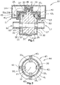
- FIG. 1 shows a schematic side view in section of a magnetic rotary slide fluid valve 10.
- the rotary slide fluid valve 10 comprises a valve housing 11 with a cylindrical housing pot 12, a bell-shaped housing cover 13 and with an actuator housing 14 placed on the housing cover 13.
- the housing pot 12 and the housing cover 13 are above the entire
- the periphery is connected to one another in a fluid-tight manner, preferably by laser welding, and form a valve chamber 15.
- the valve chamber 15 has an inlet 16 with an inlet connector 16 'and an outlet 17 with an outlet connector 17'. Furthermore, a first central valve body bearing point 19 is formed in the housing pot bottom 18 and a second central valve body bearing point 20 is formed in the housing cover 13.
- a cylindrical valve body 25 is arranged in the valve chamber 15. At the axial end of the valve body 25 directed towards the housing pot base 18, a hemispherical bearing recess 26 is formed. A bearing pin 27 is formed on the axial end of the valve body 25 directed towards the housing cover 13. The hemispherical bearing formation 26 protrudes into the valve body bearing point 19 and the bearing pin 27 protrudes into the valve body bearing point 20. In this way, the valve body 25 is rotatably supported in the valve chamber 15 about the axis of rotation 32.
- a diametrically permanently magnetized rod-shaped sensor magnet 33 is embedded in the bearing journal 27 in such a way that the cylinder axis of the sensor magnet 33 lies on the axis of rotation 32.
- the valve body 25 has, at the axial height of the inlet connection 16 ′ and the outlet connection 17 ′, a passage 28 running in the radial direction, via which the inlet 16 and the outlet 17 can be fluidically connected to one another.
- a schematically illustrated sealing element 29, 30 surrounding the inlet connector 16 'and the outlet connector 17' is arranged, which sealing element rests against an outer circumferential surface 31 of the valve body 25.
- output rotor permanent magnets 35 1 -35 4 are attached on the outer circumferential surface 31, evenly distributed over the circumference.
- the output rotor permanent magnets 35 1 -35 4 are arranged in such a way that they form an annular output rotor 36 which is alternately magnetized on the radial outer side along the circumference and which is rotatable about the axis of rotation 32.
- a bell-shaped drive part 40 is mounted on the housing cover 13 so as to be rotatable relative to the axis of rotation 32 and is fixed in the axial direction by a centrally arranged locking washer 41.
- a magnetic field sensor 45 which detects the magnetic field generated by the sensor magnet 33 in order to determine the angular position of the valve body 25, is embedded in a central position in the locking washer 41.
- each cuboid diametrically magnetized drive rotor permanent magnets 42 1 -42 4 are embedded evenly distributed over the circumference.
- the drive rotor permanent magnets 42 1 -42 4 are arranged in such a way that they form an annular drive rotor 43 which is alternately magnetized on the radially inner side along the circumference and which is rotatable about the axis of rotation 32.
- the drive rotor 43 and the output rotor 36 are coupled to one another via the magnetic fields generated by the drive rotor permanent magnets 42 1 -42 4 and by the output rotor permanent magnets 35 1 -35 4 and form as in FIG Figure 2 shown schematically a Contactless magnetic coupling 44.
- the two coupling elements i.e. the drive rotor 43 integrated in the drive part 40 with the drive rotor permanent magnets 42 1 -42 4 and the output rotor 36 attached to the valve body 25 with the output rotor permanent magnets 35 1 -35 4 are here through the housing cover 13 separated from each other in a fluid-tight manner.
- An actuator unit 50 with a valve drive 51 and with a self-locking gear 52 is also arranged in the actuator housing 14.
- the Figure 3 shows schematically an embodiment of the actuator unit 50 according to the invention.
- the valve drive 51 is formed by an electric motor 51 'which, with the aid of the self-locking gear 52 and the magnetic coupling 44, enables the valve body 25 to be rotated easily in both directions of rotation.
- the self-locking gear 52 is multi-stage and comprises a spur gear stage 53 with the spur gears 54, 55, a worm gear stage 56 with a worm 57 and a worm gear 58, which is integrated in the drive part 40, and includes two shafts 59, 60.
- a rotation of the first shaft 59 driven by the valve drive 51 about the axis of rotation 61 generates a rotation of the second shaft 59 about the axis of rotation 62 via the spur gear stage 53.
- the rotation of the shaft 59 in turn generates a rotation of the worm wheel 58 about the axis of rotation 32 via the worm 57 Since the worm wheel 58 is integrated into the drive part 40, this corresponds to a rotation of the drive part 40 about the axis of rotation 32.
- the Figure 4 shows two alternative arrangements according to the invention of the drive rotor permanent magnets 42 1 -42 4 within the drive part 40.
- the drive rotor permanent magnets 70 arranged offset from the output rotor permanent magnets 35 in the axial direction. This results in an axial component of the magnetic force acting between the drive rotor permanent magnets 70 and the driven rotor permanent magnets 35, as a result of which the valve body 25 with its bearing journal 27 is drawn into the valve body bearing point 20 in the axial direction. As a result, the axial movement play of the valve body 25 in the valve chamber 15 can be reduced.
- the drive rotor permanent magnets 71 When running after the Figure 4b the drive rotor permanent magnets 71 are tilted relative to the output rotor permanent magnets 35 so that the mutually facing magnetic surfaces of the drive rotor permanent magnets 71 and the output rotor permanent magnets 35 have an angle ⁇ between 5 ° and 45 ° to one another.
- the tilted arrangement of the drive rotor permanent magnets 71 also generates a magnetic force in the axial direction on the valve body 25, as a result of which the axial play of the valve body 25 in the valve chamber 15 can be reduced.
- the Figure 5 shows alternative versions of the drive rotor 80, 82 and the output rotor 84.
- the drive rotor 80 is designed as a magnet ring 81 which is permanently magnetized alternately along the circumference.
- the driven rotor 84 is also designed as a magnet ring 85 that is permanently magnetized alternately along the circumference.
- the drive rotor 82 has twelve drive rotor permanent magnets 83 1 -83 12 evenly distributed over the circumference of the drive rotor 82.
- the output rotor 36 and thus also the valve body 25 can be preloaded in the tangential direction. This allows the movement play of the valve body 25 to be reduced in the tangential direction.
- the magnetic rotary slide valve according to the invention is not limited to the rotary slide valve described.
- the number of inlet nozzles, outlet nozzles and passage channels can differ from the exemplary embodiment described.
- the multi-stage self-locking gearing also allows the components of the actuator unit, i.e. the valve drive and the gearing, to be arranged in a space-optimized manner, whereby the space required can also be reduced.
Landscapes
- Engineering & Computer Science (AREA)
- General Engineering & Computer Science (AREA)
- Mechanical Engineering (AREA)
- Electrically Driven Valve-Operating Means (AREA)
Description
Die Erfindung betrifft ein magnetisches Drehschieberfluidventil, insbesondere zur Verwendung im Kühlkreislauf eines Kraftfahrzeugs. Das magnetisches Drehschieberfluidventil umfasst ein Ventilgehäuse mit einem Gehäusetopf und einem Gehäusedeckel, das einen Ventilraum aufweist, einen innerhalb des Ventilraums um eine Drehachse drehbar gelagerten Ventilkörper, und eine Magnetkupplung mit einem mit dem Ventilkörper verbundenen Abtriebsrotor mit mindestens einem Abtriebsrotor-Permanentmagneten und einem außerhalb des Ventilraums angeordneten Antriebsrotor mit mindestens einem Antriebsrotor-Permanentmagneten, wobei der Antriebsrotor und der Abtriebsrotor über magnetische Kräfte gekoppelt sind und fluiddicht voneinander getrennt sind, zur Kopplung des Ventilkörpers mit einem Ventilantrieb, wobei der Abtriebsrotor an der radialen Außenseite entlang des Umfangs alternierend magnetisiert ist, der Antriebsrotor an der radialen Innenseite entlang des Umfangs alternierend magnetisiert ist, und der Antriebsrotor ringförmig ausgebildet ist und den Abtriebsrotor zumindest teilweise in Axialrichtung umschließt.The invention relates to a magnetic rotary slide fluid valve, in particular for use in the cooling circuit of a motor vehicle. The magnetic rotary slide fluid valve comprises a valve housing with a housing pot and a housing cover, which has a valve chamber, a valve body rotatably mounted inside the valve chamber about an axis of rotation, and a magnetic coupling with an output rotor connected to the valve body with at least one output rotor permanent magnet and one outside the valve chamber arranged drive rotor with at least one drive rotor permanent magnet, wherein the drive rotor and the output rotor are coupled via magnetic forces and are fluid-tightly separated from each other, for coupling the valve body to a valve drive, the output rotor being magnetized alternately on the radial outer side along the circumference, the drive rotor is magnetized alternately on the radial inside along the circumference, and the drive rotor is annular and at least partially encloses the output rotor in the axial direction.
Magnetische Drehschieberfluidventile sind aus dem Stand der Technik bekannt. Magnetische Drehschieberfluidventile weisen ein drehbares Ventilglied und eine magnetische Kupplung zur Kopplung des Ventilglieds mit einem Ventilantrieb auf. Die magnetische Kupplung umfasst mindestens zwei magnetische Kupplungselemente, die einen Magnetkreis bilden. Die kontaktlose magnetische Kupplung ermöglicht es den Ventilantrieb ohne spezielle Dichtungselemente fluiddicht von dem fluiddurchflossenen Ventilraum zu trennen, zum Beispiel durch eine Gehäusewand.Magnetic rotary slide fluid valves are known in the art. Magnetic rotary slide fluid valves have a rotatable valve member and a magnetic coupling for coupling the valve member to a valve drive. The magnetic coupling comprises at least two magnetic coupling elements which form a magnetic circuit. The contactless magnetic coupling enables the valve drive to be separated in a fluid-tight manner from the valve chamber through which the fluid flows, without special sealing elements, for example by means of a housing wall.
Aus der
Ein gattungsgemäßes magnetisches Drehschieberfluidventil ist beispielsweise aus der
Aus der gattungsfremden
Es stellt sich daher die Aufgabe, ein magnetisches Drehschieberfluidventil zu schaffen, welches einen geringen Bauraum aufweist, dadurch flexibel einsetzbar ist und eine präzise Ermittlung der Position des Abtriebsrotors ermöglicht.The object is therefore to create a magnetic rotary slide fluid valve which has a small installation space, can therefore be used flexibly and enables the position of the output rotor to be determined precisely.
Diese Aufgabe wird durch ein magnetisches Drehschieberfluidventil mit den Merkmalen des Anspruchs 1 gelöst.This object is achieved by a magnetic rotary slide fluid valve with the features of claim 1.
Erfindungsgemäß weist das magnetische Drehschieberfluidventil einen außerhalb des Ventilraums in einem auf den Gehäusedeckel aufgesetzten Aktorgehäuse angeordneten Magnetfeldsensor zur Detektion der Winkellage des Ventilkörpers auf, wobei an dem Ventilkörper in einem an dem zum Gehäusedeckel gerichteten axialen Ende des Ventilkörpers ausgeformten Lager-Zapfen ein permanentmagnetisierter Sensormagnet angebracht ist und der Magnetfeldsensor das von dem Sensormagnet generierte Magnetfeld detektiert. Der Magnetfeldsensor ist außerhalb des fluiddurchflossenen Ventilraums angeordnet, wodurch keine elektrischen Verbindungen in den fluiddurchflossenen Ventilraum notwendig sind. Über einen solchen Magnetfeldsensor ist es möglich die Stellung des Rotors genau zu ermitteln, so dass eine präzise Verstellung des Ventilkörpers möglich ist. Als Magnetfeldsensor könnte dabei beispielsweise ein Hallsensor zum Einsatz kommen. Durch eine Anordnung des Sensormagneten und des Magnetfeldsensors in geringem Abstand können Störeinflüsse im Magnetfeldsensor-Signal reduziert werden, wodurch die Genauigkeit der Winkellage-Detektion verbessert werden kann. Um die magnetischen Streufelder des Antriebsrotors und des Abtriebsrotors zu reduzieren und somit die magnetische Kopplung zwischen den beiden Rotoren zu verbessern, kann sowohl für den Antriebsrotor als auch für den Abtriebsrotor ein magnetischer Rückschluss, beispielweise in Form einer ferromagnetischen Hülse, vorgesehen werden.According to the invention, the magnetic rotary slide fluid valve has a magnetic field sensor, which is arranged outside the valve chamber in an actuator housing placed on the housing cover, for detecting the angular position of the valve body, a permanently magnetized sensor magnet being attached to the valve body in a bearing pin formed on the axial end of the valve body directed towards the housing cover and the magnetic field sensor detects the magnetic field generated by the sensor magnet. The magnetic field sensor is arranged outside the valve chamber through which fluid flows, so that no electrical connections are necessary in the valve chamber through which fluid flows. Such a magnetic field sensor makes it possible to determine the position of the rotor precisely, so that precise adjustment of the valve body is possible. A Hall sensor, for example, could be used as the magnetic field sensor. By arranging the sensor magnet and the magnetic field sensor at a short distance, interference in the magnetic field sensor signal can be reduced, whereby the Accuracy of the angular position detection can be improved. In order to reduce the magnetic stray fields of the drive rotor and the output rotor and thus improve the magnetic coupling between the two rotors, a magnetic return path, for example in the form of a ferromagnetic sleeve, can be provided for both the drive rotor and the output rotor.
In einer bevorzugten Ausführung ist der ringförmige Antriebsrotor in ein glockenförmiges Antriebsteil integriert, das den Abtriebsrotor zumindest teilweise in Axialrichtung umfasst. Das glockenförmige Antriebsteil erlaubt eine einfache Lagerung des Antriebsrotors in axialer sowie radialer Richtung.In a preferred embodiment, the ring-shaped drive rotor is integrated into a bell-shaped drive part which at least partially surrounds the output rotor in the axial direction. The bell-shaped drive part allows the drive rotor to be easily supported in the axial and radial directions.
Vorzugsweise umfasst das Ventilgehäuse einen im Wesentlichen zylindrischen Gehäusetopf mit einer ersten zentralen axialen Ventilkörper-Lagerstelle, einen Gehäusedeckel mit einer zweiten zentralen axialen Ventilkörper-Lagerstelle, der den Gehäusetopf fluiddicht verschließt, und ein auf den Gehäusedeckel aufgesetztes Aktorgehäuse. Der Ventilraum wird hierbei durch den Gehäusetopf und den Gehäusedeckel gebildet. Dieser Aufbau ermöglicht eine einfache und kostengünstige Herstellung des Ventilgehäuses. Das auf den Gehäusedeckel aufgesetzte Aktorgehäuse erlaubt zusätzlich eine einfache Wartung des Drehschieberventils.The valve housing preferably comprises a substantially cylindrical housing pot with a first central axial valve body bearing point, a housing cover with a second central axial valve body bearing point, which closes the housing pot in a fluid-tight manner, and an actuator housing placed on the housing cover. The valve chamber is formed here by the housing pot and the housing cover. This structure enables simple and inexpensive manufacture of the valve housing. The actuator housing placed on the housing cover also allows easy maintenance of the rotary slide valve.
In einer vorteilhaften Ausgestaltung ist der Ventilantrieb in dem aufgesetzten Aktorgehäuse angeordnet, und somit durch den Gehäusedeckel fluiddicht vom fluiddurchflossenen Ventilraum getrennt. Zusätzlich ist der Ventilantrieb leicht zugänglich und somit einfach zu warten.In an advantageous embodiment, the valve drive is arranged in the attached actuator housing and is thus separated in a fluid-tight manner from the valve chamber through which the fluid flows by the housing cover. In addition, the valve drive is easily accessible and therefore easy to maintain.
In einer besonders vorteilhaften Ausgestaltung ist der Antriebsrotor der Magnetkupplung in dem Aktorgehäuse angeordnet und gleitend auf dem Gehäusedeckel gelagert. Dies ermöglicht eine einfache Lagerung des Antriebsrotors, wobei der Antriebsrotor durch den Gehäusedeckel fluiddicht vom fluiddurchflossenen Ventilraum getrennt ist. Ferner erlaubt diese Anordnung einen modularen Aufbau des Drehschieberventils, da die komplette Antriebseinheit, also der Ventilantrieb und der Antriebsrotor der Magnetkupplung, in dem aufgesetzten Aktorgehäuse angeordnet werden kann und somit einfach ausgetauscht werden kann.In a particularly advantageous embodiment, the drive rotor of the magnetic coupling is arranged in the actuator housing and slidably mounted on the housing cover. This enables easy storage of the Drive rotor, the drive rotor being separated from the valve chamber through which the fluid flows by the housing cover in a fluid-tight manner. Furthermore, this arrangement allows a modular construction of the rotary slide valve, since the complete drive unit, i.e. the valve drive and the drive rotor of the magnetic coupling, can be arranged in the attached actuator housing and can thus be easily exchanged.
Vorzugsweise ist der Antriebsrotor über ein selbsthemmendes Getriebe mit dem Ventilantrieb verbunden. Durch die Verwendung einer geeigneten Übersetzung des Getriebes ermöglicht dies eine optimierte Regelung des Drehschieberfluidventils. Des Weiteren müssen der Ventilantrieb und der Antriebsrotor nicht mehr koaxial angeordnet sein, wodurch eine bauraumoptimierte Anordnung des Ventilantriebs ermöglicht wird.The drive rotor is preferably connected to the valve drive via a self-locking gear. By using a suitable translation of the transmission, this enables an optimized control of the rotary slide fluid valve. Furthermore, the valve drive and the drive rotor no longer have to be arranged coaxially, which enables the valve drive to be arranged in a space-optimized manner.
In einer vorteilhaften Ausführungsform weist das selbsthemmende Getriebe eine Stirnradgetriebestufe und eine Schneckengetriebestufe auf. Dieses mehrstufige selbsthemmende Getriebe erlaubt eine hohe Momentübersetzung auf kleinem Raum.In an advantageous embodiment, the self-locking gear has a spur gear stage and a worm gear stage. This multi-stage self-locking gear allows high torque transmission in a small space.
In einer besonders vorteilfahren Ausführungsform ist der Antriebsrotor der Magnetkupplung in das Schneckenrad der Schneckengetriebestufe des selbsthemmenden Getriebes integriert. Hierdurch kann der Antriebsrotor auf einfache Weise ohne Vorsehen von weiteren Bauteilen und somit platzsparend ausgeführt werden.In a particularly advantageous embodiment, the drive rotor of the magnetic coupling is integrated into the worm wheel of the worm gear stage of the self-locking gear. As a result, the drive rotor can be designed in a simple manner without the provision of further components and thus in a space-saving manner.
In einer bevorzugten Ausgestaltung weist der Antriebsrotor oder der Abtriebsrotor entlang des Umfangs alternierend permanentmagnetisierte Magnetsegmente auf. Die Verwendung von permanentmagnetisierten Magnetsegmenten erlaubt eine einfache Ausführung des Antriebsrotors und des Abtriebsrotors. Beispielsweise kann der Abtriebsrotor durch an der radialen Außenseite des Ventilkörpers angebrachte oder entlang des Umfangs in den Ventilkörper eingebettete Magnetsegmente ausgeführt werden.In a preferred embodiment, the drive rotor or the driven rotor has permanently magnetized magnet segments alternating along the circumference. The use of permanently magnetized magnet segments allows a simple design of the drive rotor and the output rotor. For example, the output rotor can be attached to the radial outside of the valve body or along the Perimeter embedded in the valve body magnet segments are executed.
In einer alternativen Ausführungsform kann der Antriebsrotor oder der Abtriebsrotor einen entlang des Umfangs alternierend permanentmagnetisierten Magnetring aufweisen. Dies erlaubt eine einfache Ausführung des Antriebsrotors oder des Abtriebsrotors ohne Vorsehen von weiteren Bauteilen.In an alternative embodiment, the drive rotor or the driven rotor can have a magnet ring that is permanently magnetized alternately along the circumference. This allows a simple design of the drive rotor or the output rotor without the provision of further components.
In einer vorteilhaften Ausführungsform sind der mindestens eine Antriebsrotor-Permanentmagnet und der mindestens eine Abtriebsrotor-Permanentmagnet auf unterschiedlicher axialer Höhe angeordnet. Auf diese Weise kann eine magnetische Kraft in Axialrichtung auf den Ventilkörper erzeugt werden welche den Ventilkörper beispielsweise in einer axialen Ventilkörper-Lagerstelle fixiert und somit das Bewegungsspiel des Ventilkörpers verringert.In an advantageous embodiment, the at least one drive rotor permanent magnet and the at least one driven rotor permanent magnet are arranged at different axial heights. In this way, a magnetic force can be generated in the axial direction on the valve body, which fixes the valve body, for example, in an axial valve body bearing point and thus reduces the movement play of the valve body.
In einer weiteren vorteilhaften Ausgestaltung sind der mindestens eine Antriebsrotor-Permanentmagnet und der mindestens eine Abtriebsrotor-Permanentmagnet derart angeordnet, dass die zueinander gerichteten Magnetflächen des mindestens einen Antriebsrotor-Permanentmagneten und des mindestens einen Abtriebsrotor-Permanentmagneten einen Winkel α zwischen 5° und 45° zueinander aufweisen. Hierdurch kann ebenfalls eine axiale magnetische Kraft auf den Ventilkörper generiert werden, um den Ventilkörper in einer axialen Ventilkörper-Lagerstelle zu fixieren und somit das Bewegungsspiel des Ventilkörpers zu reduzieren.In a further advantageous embodiment, the at least one drive rotor permanent magnet and the at least one output rotor permanent magnet are arranged in such a way that the mutually facing magnetic surfaces of the at least one drive rotor permanent magnet and the at least one output rotor permanent magnet are at an angle α between 5 ° and 45 ° exhibit. As a result, an axial magnetic force can also be generated on the valve body in order to fix the valve body in an axial valve body bearing point and thus to reduce the movement play of the valve body.
In einer vorteilhaften Ausführungsform weisen der Antriebsrotor und der Abtriebsrotor eine unterschiedliche Anzahl magnetischer Pole auf. Dies erlaubt eine Vorspannung der magnetischen Kupplung in Tangentialrichtung, wodurch das Bewegungsspiel des Ventilkörpers in Tangentialrichtung reduziert werden kann.In an advantageous embodiment, the drive rotor and the driven rotor have a different number of magnetic poles. This allows the magnetic coupling to be pretensioned in the tangential direction, as a result of which the movement play of the valve body in the tangential direction can be reduced.
Vorzugsweise ist der Ventilkörper innerhalb des Ventilraums axial durch mindestens einen Lager-Zapfen gelagert. Lager-Zapfen können als Bestandteil des Ventilkörpers ausgeformt sein, wodurch der Ventilkörper ohne Vorsehen von weiteren Bauteilen auf einfache Weise in dem Ventilraum gelagert werden kann.The valve body is preferably supported axially within the valve chamber by at least one bearing journal. Bearing pins can be formed as part of the valve body, whereby the valve body can be stored in the valve chamber in a simple manner without the provision of further components.
In einer bevorzugten Ausgestaltung ist der Ventilantrieb ein Elektromotor. Der Elektromotor erlaubt einen besonders einfachen und genauen Antrieb des Ventils in beide Rotationsrichtungen.In a preferred embodiment, the valve drive is an electric motor. The electric motor allows a particularly simple and precise drive of the valve in both directions of rotation.
Weitere Einzelheiten und Vorteile der vorliegenden Erfindung ergeben sich aus der nachfolgenden Beschreibung der Ausführungsbeispiele in Verbindung mit den beigefügten Figuren, wobei
-
Figur 1 eine schematische Seitenansicht in geschnittener Darstellung eines erfindungsgemäßen magnetischen Drehschieberfluidventils zeigt, -
Figur 2 einen schematischen Querschnitt der Magnetkupplung eines erfindungsgemäßen magnetischen Drehschieberfluidventils zeigt, -
Figur 3 eine schematische Darstellung einer Aktoreinheit eines erfindungsgemäßen magnetischen Drehschieberfluidventils zeigt, -
Figur 4 zwei alternative Anordnungen der Antriebsrotor-Permanentmagnete eines erfindungsgemäßen magnetischen Drehschieberfluidventils zeigt, und -
Figur 5 alternative Ausführungen eines Antriebsrotors und eines Abtriebsrotors eines erfindungsgemäßen magnetischen Drehschieberfluidventils zeigt.
-
Figure 1 shows a schematic side view in section of a magnetic rotary slide fluid valve according to the invention, -
Figure 2 shows a schematic cross section of the magnetic coupling of a magnetic rotary slide fluid valve according to the invention, -
Figure 3 shows a schematic representation of an actuator unit of a magnetic rotary slide fluid valve according to the invention, -
Figure 4 shows two alternative arrangements of the drive rotor permanent magnets of a magnetic rotary slide fluid valve according to the invention, and -
Figure 5 shows alternative embodiments of a drive rotor and an output rotor of a magnetic rotary slide fluid valve according to the invention.
Die
Der Ventilraum 15 weist einen Einlass 16 mit einem Einlassstutzen 16' und einen Auslass 17 mit einem Auslassstutzen 17' auf. Ferner ist im Gehäusetopf-Boden 18 eine erste zentrale Ventilkörper-Lagerstelle 19 ausgebildet und ist im Gehäusedeckel 13 eine zweite zentrale Ventilkörper-Lagerstelle 20 ausgebildet.The
In dem Ventilraum 15 ist ein zylinderförmiger Ventilkörper 25 angeordnet. An dem zum Gehäusetopf-Boden 18 gerichteten axialen Ende des Ventilkörpers 25 ist eine halbkugelförmige Lager-Ausformung 26 ausgeformt. An dem zum Gehäusedeckel 13 gerichteten axialen Ende des Ventilkörpers 25 ist ein Lager-Zapfen 27 ausgeformt. Die halbkugelförmige Lager-Ausformung 26 ragt in die Ventilkörper-Lagerstelle 19 und der Lager-Zapfen 27 ragt in die Ventilkörper-Lagerstelle 20. Auf diese Weise ist der Ventilkörper 25 in dem Ventilraum 15 drehbar um die Drehachse 32 gelagert. In den Lager-Zapfen 27 ist ein diametral permanentmagnetisierter stabförmiger Sensormagnet 33 derart eingebettet, dass die Zylinderachse des Sensormagneten 33 auf der Drehachse 32 liegt.A
Der Ventilkörper 25 weist auf axialer Höhe des Einlassstutzens 16' und des Auslassstutzens 17' einen in Radialrichtung verlaufenden Durchlasskanal 28 auf, über den der Einlass 16 und der Auslass 17 fluidisch miteinander verbunden werden können. An dem zum Ventilkörper 25 weisenden Ende des Einlassstutzens 16' und des Auslassstutzens 17' ist jeweils ein den Einlassstutzen 16' bzw. den Auslassstutzen 17' umgebendes schematisch dargestelltes Dichtelement 29,30 angeordnet, welches dichtend an einer Außenumfangsfläche 31 des Ventilkörpers 25 anliegt. Über eine Drehung des Ventilkörpers 25 um die Drehachse 32 und den damit einstellbaren Grad der Überdeckung des Durchlasskanals 28 mit dem Einlassstutzen 16' bzw. dem Auslassstutzen 17' kann die Durchflussmenge des Drehschieberfluidventils 10 reguliert werden.The
An dem zum Gehäusedeckel 13 gerichteten axialen Ende des Ventilkörpers 25 sind auf der Außenumfangsfläche 31 gleichmäßig über den Umfang verteilt vier quaderförmige diametral-magnetisierte Abtriebsrotor-Permanentmagnete 351-354 angebracht. Die Abtriebsrotor-Permanentmagnete 351-354 sind derart angeordnet, dass sie einen ringförmigen an der radialen Außenseite entlang des Umfangs alternierend magnetisierten Abtriebsrotor 36 bilden, der um die Drehachse 32 drehbar ist.At the axial end of the
In dem Aktorgehäuse 14 ist ein glockenförmiges Antriebsteil 40 drehbar zu der Drehachse 32 gleitend auf dem Gehäusedeckel 13 gelagert und in Axialrichtung durch eine zentral angeordnete Sicherungsscheibe 41 fixiert. In der Sicherungsscheibe 41 ist in zentraler Lage ein Magnetfeldsensor 45 eingelassen, der das von dem Sensormagneten 33 erzeugte Magnetfeld detektiert um die Drehwinkelposition des Ventilkörpers 25 zu bestimmen.In the
In dem zu dem Gehäusedeckel 13 gerichteten ringförmigen Ende des glockenförmigen Antriebsteils 40 sind gleichmäßig über den Umfang verteilt vier quaderförmige diametral-magnetisierte Antriebsrotor-Permanentmagnete 421-424 eingelassen. Die Antriebsrotor-Permanentmagnete 421-424 sind derart angeordnet, dass sie einen ringförmigen an der radialen Innenseite entlang des Umfangs alternierend magnetisierten Antriebsrotor 43 bilden, der um die Drehachse 32 drehbar ist.In the annular end of the bell-shaped
Der Antriebsrotor 43 und der Abtriebsrotor 36 sind über die von den Antriebsrotor-Permanentmagneten 421-424 und von den Abtriebsrotor-Permanentmagneten 351-354 generierten Magnetfelder miteinander gekoppelt und bilden wie in der
In dem Aktorgehäuse 14 ist ferner eine Aktoreinheit 50 mit einem Ventilantrieb 51 und mit einem selbsthemmenden Getriebe 52 angeordnet. Die
Eine Drehung der vom Ventilantrieb 51 angetriebenen ersten Welle 59 um die Drehachse 61 erzeugt über die Stirnradgetriebestufe 53 eine Drehung der zweiten Welle 59 um die Drehachse 62. Die Drehung der Welle 59 erzeugt wiederum über die Schnecke 57 eine Drehung des Schneckenrads 58 um die Drehachse 32. Da das Schneckenrad 58 in das Antriebsteil 40 integriert ist, entspricht dies somit einer Drehung des Antriebsteils 40 um die Drehachse 32. Auf Grund der magnetischen Kopplung zwischen dem in das Antriebsteil 40 integrierten Antriebsrotor 43 und dem an dem Ventilkörper 25 angebrachten Abtriebsrotor 36 wird eine Drehung des Antriebsteils 40 direkt in eine Drehung des Ventilkörpers 25 umgesetzt.A rotation of the
Die
Bei der Ausführung nach der
Die
Das erfindungsgemäße magnetische Drehschieberventil ist nicht auf das beschriebene Drehschieberventil begrenzt. So kann sich beispielsweise die Anzahl der Einlassstutzen, der Auslassstutzen und der Durchlasskanäle von dem beschriebenen Ausführungsbeispiel unterscheiden.The magnetic rotary slide valve according to the invention is not limited to the rotary slide valve described. For example, the number of inlet nozzles, outlet nozzles and passage channels can differ from the exemplary embodiment described.
Auf Grund der radialen Anordnung des Antriebsrotors und des Abtriebsrotors benötigt die Magnetkupplung nur einen geringen axialen Bauraum. Das mehrstufige selbsthemmende Getriebe erlaubt es zusätzlich, die Komponenten der Aktoreinheit, also den Ventilantrieb und das Getriebe, bauraumoptimiert anzuordnen, wodurch der benötigte Bauraum zusätzlich verringert werden kann.Due to the radial arrangement of the drive rotor and the output rotor, the magnetic coupling only requires a small amount of axial space. The multi-stage self-locking gearing also allows the components of the actuator unit, i.e. the valve drive and the gearing, to be arranged in a space-optimized manner, whereby the space required can also be reduced.
- 1010
- DrehschieberfluidventilRotary slide fluid valve
- 1111
- VentilgehäuseValve body
- 1212th
- GehäusetopfHousing pot
- 1313th
- GehäusedeckelHousing cover
- 1414th
- AktorgehäuseActuator housing
- 1515th
- VentilraumValve space
- 1616
- Einlassinlet
- 16'16 '
- EinlassstutzenInlet port
- 1717th
- AuslassOutlet
- 17'17 '
- AuslassstutzenOutlet port
- 1818th
- Gehäusetopf-BodenHousing pot bottom
- 1919th
- Ventilkörper-LagerstelleValve body bearing
- 2020th
- Ventilkörper-LagerstelleValve body bearing
- 2525th
- VentilkörperValve body
- 2626th
- Lager-AusformungBearing molding
- 2727
- Lager-ZapfenBearing journal
- 2828
- DurchlasskanalPassage channel
- 2929
- DichtelementSealing element
- 3030th
- DichtelementSealing element
- 3131
- AußenumfangsflächeOuter peripheral surface
- 3232
- DrehachseAxis of rotation
- 3333
- SensormagnetSensor magnet
- 351-354351-354
- Abtriebsrotor-PermanentmagneteOutput rotor permanent magnets
- 3636
- AbtriebsrotorOutput rotor
- 4040
- AntriebsteilDrive part
- 4141
- SicherungsscheibeLock washer
- 421-424421-424
- Antriebsrotor-PermanentmagneteDrive rotor permanent magnets
- 4343
- AntriebsrotorDrive rotor
- 4444
- MagnetkupplungMagnetic coupling
- 4545
- MagnetfeldsensorMagnetic field sensor
- 5050
- AktoreinheitActuator unit
- 5151
- VentilantriebValve drive
- 51'51 '
- ElektromotorElectric motor
- 5252
- selbsthemmendes Getriebeself-locking gear
- 5353
- StirnradgetriebestufeSpur gear stage
- 5454
- Stirn-ZahnradSpur gear
- 5555
- Stirn-ZahnradSpur gear
- 5656
- SchneckengetriebestufeWorm gear stage
- 5757
- Schneckeslug
- 5858
- SchneckenradWorm gear
- 5959
- Wellewave
- 6060
- Wellewave
- 6161
- DrehachseAxis of rotation
- 6262
- DrehachseAxis of rotation
- 7070
- Antriebsrotor-PermanentmagneteDrive rotor permanent magnets
- 7171
- Antriebsrotor-PermanentmagneteDrive rotor permanent magnets
- 8080
- AntriebsrotorDrive rotor
- 8181
- MagnetringMagnetic ring
- 8282
- AntriebsrotorDrive rotor
- 831-8312831-8312
- Antriebsrotor-PermanentmagneteDrive rotor permanent magnets
- 8484
- AbtriebsrotorOutput rotor
- 8585
- MagnetringMagnetic ring
Claims (15)
- Magnetic rotary slide fluid valve (10) comprising a valve housing (11) having a cylindrical housing can (12) and a bell-shaped housing cover (13) with a valve chamber (15), a valve body (25) mounted within the valve chamber (15) rotatably about an axis of rotation (32), a magnetic coupling (44) with an output rotor (36) mounted to the valve body (25) and having at least one output rotor permanent magnet (351-354), and with a drive rotor (43) arranged outside the valve chamber (15) and having at least one drive rotor permanent magnet (421-424), wherein the drive rotor (43) and the output rotor (36) are coupled by magnetic forces and are separated from each other in a fluid-tight manner, for coupling the valve body (25) to a valve drive (51), wherein the output rotor (36) is alternately magnetized along the circumference on the radial outside, the drive rotor (43) is alternately magnetized along the circumference on the radially inner side, and the drive rotor (43) is designed annular and encloses the output rotor (36) at least partially in the axial direction,
characterized in that
the magnetic rotary slide fluid valve (10) comprises a magnetic field sensor (45) for the detection of the angular position of the valve body (25), the magnetic field sensor (45) being arranged outside the valve chamber (15) in an actuator housing (14) set on the housing cover (13), wherein a permanently magnetized sensor magnet (33) is mounted on the valve body (25) in a bearing pin (27) formed at an axial end of the valve body (25) directed to the housing cover (13), and the magnetic field sensor (45) detects the magnetic field generated by the sensor magnet (33). - Magnetic rotary slide fluid valve (10) according to claim 1, characterized in that the annular drive rotor (43) is integrated in a bell-shaped drive element (40) that encloses the output rotor (36) at least partly in the axial direction.
- Magnetic rotary slide fluid valve (10) according to claim 1 or 2, characterized in that the cylindrical housing can (12) of the valve housing (11) has a first central axial valve body bearing point (19), and the housing cover (13) closing the housing can (12) in a fluid-tight manner has a second central axial valve body bearing point (20).
- Magnetic rotary slide fluid valve (10) according to claim 3, characterized in that the valve drive (51) adapted to be coupled with the valve body (25) can be arranged in the actuator housing (14).
- Magnetic rotary slide fluid valve (10) according to claim 3 or 4, characterized in that, in the actuator housing (14), the drive rotor (43) is slidably mounted on the housing cover (13).
- Magnetic rotary slide fluid valve (10) according to one of the preceding claims, characterized in that the drive rotor (43) is adapted to be coupled with the valve drive (51) via a self-locking gear (52).
- Magnetic rotary slide fluid valve (10) according to claim 6, characterized in that the self-locking gear (52) comprises a spur gear stage (53) and a worm gear stage (56).
- Magnetic rotary slide fluid valve (10) according to claim 7, characterized in that the drive rotor (43) is integrated into the worm wheel (58) of the worm gear stage (56).
- Magnetic rotary slide fluid valve (10) according to one of the preceding claims, characterized in that the drive rotor (43) or the output rotor (36) comprises magnet segments (421-424) being alternatingly permanently magnetized along the circumference.
- Magnetic rotary slide fluid valve (10) according to one of the preceding claims, characterized in that the drive rotor (80) or the output rotor (84) comprises a magnet ring (81, 85) being alternatingly permanently magnetized along the circumference.
- Magnetic rotary slide fluid valve (10) according to one of the preceding claims, characterized in that the at least one drive motor permanent magnet (70) and the at least one output rotor permanent magnet (351 - 354) are arranged at different axial heights.
- Magnetic rotary slide fluid valve (10) according to one of the preceding claims, characterized in that the at least one drive rotor permanent magnet (71) and the at least one output rotor permanent magnet (351-354) are arranged such that the magnet surfaces of at least one drive rotor permanent magnet (71) and the at least one output rotor permanent magnet (351-354) facing each other have an angle α between 5° and 45° with respect to each other.
- Magnetic rotary slide fluid valve (10) according to one of the preceding claims, characterized in that the drive rotor (82) and the output rotor (26) have different numbers of magnetic poles.
- Magnetic rotary slide fluid valve (10) according to one of the preceding claims, characterized in that, in the valve chamber (15), the valve body (25) is axially supported by the bearing pin (27).
- Magnetic rotary slide fluid valve (10) according to one of the preceding claims, characterized in that the valve drive (51) is an electric motor (51').
Applications Claiming Priority (1)
| Application Number | Priority Date | Filing Date | Title |
|---|---|---|---|
| DE102017128127.4A DE102017128127B4 (en) | 2017-11-28 | 2017-11-28 | Magnetic rotary fluid valve |
Publications (2)
| Publication Number | Publication Date |
|---|---|
| EP3489559A1 EP3489559A1 (en) | 2019-05-29 |
| EP3489559B1 true EP3489559B1 (en) | 2021-12-01 |
Family
ID=64082903
Family Applications (1)
| Application Number | Title | Priority Date | Filing Date |
|---|---|---|---|
| EP18203017.1A Active EP3489559B1 (en) | 2017-11-28 | 2018-10-29 | Magnetic crank up slider fluid valve |
Country Status (2)
| Country | Link |
|---|---|
| EP (1) | EP3489559B1 (en) |
| DE (1) | DE102017128127B4 (en) |
Families Citing this family (3)
| Publication number | Priority date | Publication date | Assignee | Title |
|---|---|---|---|---|
| PL4042044T3 (en) * | 2019-10-10 | 2023-12-27 | Avk Holding A/S | A method for determining a position of a blocking element in a valve, a sensor system and use of a sensor system |
| DE102021201319A1 (en) * | 2021-02-12 | 2022-08-18 | Robert Bosch Gesellschaft mit beschränkter Haftung | Adjusting device, in particular for use under water, with a magnetic coupling |
| DE102022111976A1 (en) | 2022-05-12 | 2023-11-16 | Woco Industrietechnik Gmbh | Control valve and pipe system |
Citations (2)
| Publication number | Priority date | Publication date | Assignee | Title |
|---|---|---|---|---|
| US3134404A (en) * | 1961-02-27 | 1964-05-26 | William B Jaspert | Electro-magnetically operated floating armature valves |
| WO2003100950A1 (en) * | 2002-05-25 | 2003-12-04 | Robert Bosch Gmbh | Electric motor driven actuator |
Family Cites Families (13)
| Publication number | Priority date | Publication date | Assignee | Title |
|---|---|---|---|---|
| US3347262A (en) * | 1965-09-22 | 1967-10-17 | Mark Associates Inc | Magnet actuated sealed valve |
| US4327892A (en) * | 1980-09-08 | 1982-05-04 | Autoclave Engineers, Inc. | Normally magnetically actuated valve with novel nonmagnetic override |
| DE8715977U1 (en) * | 1987-12-03 | 1988-01-21 | Franz Klaus Union Armaturen, Pumpen Gmbh & Co, 4630 Bochum, De | |
| US5083744A (en) * | 1991-03-08 | 1992-01-28 | Morotta Scientific Controls, Inc. | Motor-operated valve |
| DE102005041973A1 (en) * | 2005-09-03 | 2007-09-13 | Werth, Vladimir, Dipl.-Ing. | Permanent magnetic coupler for use in multi-function machine, has chamber adjustable in axial direction, where rotary torque transfer occurs from shaft to belt pulley without disassembly of coupler |
| FR2947606B1 (en) | 2009-07-03 | 2015-02-20 | Inst Francais Du Petrole | 3-WAY HYDRAULIC DISTRIBUTOR AND MAGNETIC DRIVE CONTROL |
| DE102009033160A1 (en) * | 2009-07-13 | 2011-01-27 | Porep Gmbh | Rotary valve, has valve housing, and two operating elements and closure element that are connected by magnetic clutch, where one of operating elements i.e. motor is provided on top of valve |
| IT1397055B1 (en) * | 2009-12-29 | 2012-12-28 | Soldo S R L Socio Unico | DEVICE POSITION INDICATOR OF A ROTARY VALVE AND METHOD FOR INDICATING THE POSITION OF A ROTARY VALVE |
| JP5858220B2 (en) * | 2011-10-05 | 2016-02-10 | 日本電産株式会社 | motor |
| US9377121B2 (en) * | 2011-12-03 | 2016-06-28 | Big Horn Valve, Inc. | Leak-free rotary valve with internal worm gear |
| CA2855315C (en) * | 2013-06-28 | 2021-08-10 | DePuy Synthes Products, LLC | Method and tools for implanted device |
| DE102014224151A1 (en) * | 2014-11-26 | 2016-06-02 | Mahle International Gmbh | Device for non-contact transmission of rotational movements |
| US9797521B1 (en) * | 2016-08-09 | 2017-10-24 | Edward P Davis | Rotary magnetic coupling actuated valve with external magnets and internal magnetic flux path |
-
2017
- 2017-11-28 DE DE102017128127.4A patent/DE102017128127B4/en active Active
-
2018
- 2018-10-29 EP EP18203017.1A patent/EP3489559B1/en active Active
Patent Citations (2)
| Publication number | Priority date | Publication date | Assignee | Title |
|---|---|---|---|---|
| US3134404A (en) * | 1961-02-27 | 1964-05-26 | William B Jaspert | Electro-magnetically operated floating armature valves |
| WO2003100950A1 (en) * | 2002-05-25 | 2003-12-04 | Robert Bosch Gmbh | Electric motor driven actuator |
Also Published As
| Publication number | Publication date |
|---|---|
| DE102017128127A1 (en) | 2019-05-29 |
| DE102017128127B4 (en) | 2023-05-04 |
| EP3489559A1 (en) | 2019-05-29 |
Similar Documents
| Publication | Publication Date | Title |
|---|---|---|
| EP3489559B1 (en) | Magnetic crank up slider fluid valve | |
| DE2312486C2 (en) | Electromagnetically operated wrap spring clutch | |
| DE102007020525A1 (en) | Camshaft adjuster for an internal combustion engine with integrated valve slide | |
| DE202014103691U1 (en) | Motorized servo device | |
| EP2818725A1 (en) | Centrifugal pump with axially shiftable and closable impeller | |
| WO2004018805A1 (en) | Locking device for vehicles, especially for aeroplanes | |
| EP3824249B1 (en) | Rotation angle measurement system | |
| DE102012207748A1 (en) | Swiveling device for a ship's propeller nacelle | |
| WO2010031683A2 (en) | Vacuum pump | |
| DE102022118426B4 (en) | Planetary gear | |
| EP1563587B1 (en) | Drive device provided for operating adjusting devices in motor vehicles | |
| WO2020207573A1 (en) | Rotary slide valve for a motor vehicle | |
| EP0866543A2 (en) | Positioning actuator | |
| EP1477714B1 (en) | Actuator for valves | |
| DE102018118100A1 (en) | Pump with absolute rotation angle detection | |
| DE112017006417B4 (en) | REDUCTION GEAR, VEHICLE SEAT | |
| DE102011121870B4 (en) | The magnetic sensor system | |
| DE19814078A1 (en) | Electromagnetic spring pressure brake, e.g. for lifting mechanism drive motors | |
| EP3913267A1 (en) | Actuating device for actuating a rotary slide valve | |
| DE4207978C1 (en) | Stepper motor suitable for mass prodn., e.g. for motor vehicle displays - has two coaxial coil units contg. rotor and each surrounded by stator systems | |
| DE102010005854A1 (en) | actuator | |
| DE102020210407A1 (en) | Rotary machine with position sensor | |
| EP1649576A1 (en) | Housing part of a drive unit, and counterpart | |
| DE102017220579A1 (en) | Rotor for a magnetic stirring device and magnetic stirring device | |
| EP4194720A1 (en) | Locking unit |
Legal Events
| Date | Code | Title | Description |
|---|---|---|---|
| PUAI | Public reference made under article 153(3) epc to a published international application that has entered the european phase |
Free format text: ORIGINAL CODE: 0009012 |
|
| STAA | Information on the status of an ep patent application or granted ep patent |
Free format text: STATUS: THE APPLICATION HAS BEEN PUBLISHED |
|
| AK | Designated contracting states |
Kind code of ref document: A1 Designated state(s): AL AT BE BG CH CY CZ DE DK EE ES FI FR GB GR HR HU IE IS IT LI LT LU LV MC MK MT NL NO PL PT RO RS SE SI SK SM TR |
|
| AX | Request for extension of the european patent |
Extension state: BA ME |
|
| STAA | Information on the status of an ep patent application or granted ep patent |
Free format text: STATUS: REQUEST FOR EXAMINATION WAS MADE |
|
| 17P | Request for examination filed |
Effective date: 20191129 |
|
| RBV | Designated contracting states (corrected) |
Designated state(s): AL AT BE BG CH CY CZ DE DK EE ES FI FR GB GR HR HU IE IS IT LI LT LU LV MC MK MT NL NO PL PT RO RS SE SI SK SM TR |
|
| STAA | Information on the status of an ep patent application or granted ep patent |
Free format text: STATUS: EXAMINATION IS IN PROGRESS |
|
| 17Q | First examination report despatched |
Effective date: 20200408 |
|
| STAA | Information on the status of an ep patent application or granted ep patent |
Free format text: STATUS: EXAMINATION IS IN PROGRESS |
|
| GRAJ | Information related to disapproval of communication of intention to grant by the applicant or resumption of examination proceedings by the epo deleted |
Free format text: ORIGINAL CODE: EPIDOSDIGR1 |
|
| STAA | Information on the status of an ep patent application or granted ep patent |
Free format text: STATUS: GRANT OF PATENT IS INTENDED |
|
| GRAP | Despatch of communication of intention to grant a patent |
Free format text: ORIGINAL CODE: EPIDOSNIGR1 |
|
| INTG | Intention to grant announced |
Effective date: 20210614 |
|
| GRAS | Grant fee paid |
Free format text: ORIGINAL CODE: EPIDOSNIGR3 |
|
| GRAA | (expected) grant |
Free format text: ORIGINAL CODE: 0009210 |
|
| STAA | Information on the status of an ep patent application or granted ep patent |
Free format text: STATUS: THE PATENT HAS BEEN GRANTED |
|
| AK | Designated contracting states |
Kind code of ref document: B1 Designated state(s): AL AT BE BG CH CY CZ DE DK EE ES FI FR GB GR HR HU IE IS IT LI LT LU LV MC MK MT NL NO PL PT RO RS SE SI SK SM TR |
|
| REG | Reference to a national code |
Ref country code: GB Ref legal event code: FG4D Free format text: NOT ENGLISH |
|
| REG | Reference to a national code |
Ref country code: AT Ref legal event code: REF Ref document number: 1452065 Country of ref document: AT Kind code of ref document: T Effective date: 20211215 Ref country code: CH Ref legal event code: EP |
|
| REG | Reference to a national code |
Ref country code: IE Ref legal event code: FG4D Free format text: LANGUAGE OF EP DOCUMENT: GERMAN |
|
| REG | Reference to a national code |
Ref country code: DE Ref legal event code: R096 Ref document number: 502018008028 Country of ref document: DE |
|
| REG | Reference to a national code |
Ref country code: LT Ref legal event code: MG9D |
|
| REG | Reference to a national code |
Ref country code: NL Ref legal event code: MP Effective date: 20211201 |
|
| PG25 | Lapsed in a contracting state [announced via postgrant information from national office to epo] |
Ref country code: RS Free format text: LAPSE BECAUSE OF FAILURE TO SUBMIT A TRANSLATION OF THE DESCRIPTION OR TO PAY THE FEE WITHIN THE PRESCRIBED TIME-LIMIT Effective date: 20211201 Ref country code: LT Free format text: LAPSE BECAUSE OF FAILURE TO SUBMIT A TRANSLATION OF THE DESCRIPTION OR TO PAY THE FEE WITHIN THE PRESCRIBED TIME-LIMIT Effective date: 20211201 Ref country code: FI Free format text: LAPSE BECAUSE OF FAILURE TO SUBMIT A TRANSLATION OF THE DESCRIPTION OR TO PAY THE FEE WITHIN THE PRESCRIBED TIME-LIMIT Effective date: 20211201 Ref country code: BG Free format text: LAPSE BECAUSE OF FAILURE TO SUBMIT A TRANSLATION OF THE DESCRIPTION OR TO PAY THE FEE WITHIN THE PRESCRIBED TIME-LIMIT Effective date: 20220301 |
|
| PG25 | Lapsed in a contracting state [announced via postgrant information from national office to epo] |
Ref country code: SE Free format text: LAPSE BECAUSE OF FAILURE TO SUBMIT A TRANSLATION OF THE DESCRIPTION OR TO PAY THE FEE WITHIN THE PRESCRIBED TIME-LIMIT Effective date: 20211201 Ref country code: PL Free format text: LAPSE BECAUSE OF FAILURE TO SUBMIT A TRANSLATION OF THE DESCRIPTION OR TO PAY THE FEE WITHIN THE PRESCRIBED TIME-LIMIT Effective date: 20211201 Ref country code: NO Free format text: LAPSE BECAUSE OF FAILURE TO SUBMIT A TRANSLATION OF THE DESCRIPTION OR TO PAY THE FEE WITHIN THE PRESCRIBED TIME-LIMIT Effective date: 20220301 Ref country code: LV Free format text: LAPSE BECAUSE OF FAILURE TO SUBMIT A TRANSLATION OF THE DESCRIPTION OR TO PAY THE FEE WITHIN THE PRESCRIBED TIME-LIMIT Effective date: 20211201 Ref country code: HR Free format text: LAPSE BECAUSE OF FAILURE TO SUBMIT A TRANSLATION OF THE DESCRIPTION OR TO PAY THE FEE WITHIN THE PRESCRIBED TIME-LIMIT Effective date: 20211201 Ref country code: GR Free format text: LAPSE BECAUSE OF FAILURE TO SUBMIT A TRANSLATION OF THE DESCRIPTION OR TO PAY THE FEE WITHIN THE PRESCRIBED TIME-LIMIT Effective date: 20220302 Ref country code: ES Free format text: LAPSE BECAUSE OF FAILURE TO SUBMIT A TRANSLATION OF THE DESCRIPTION OR TO PAY THE FEE WITHIN THE PRESCRIBED TIME-LIMIT Effective date: 20211201 |
|
| PG25 | Lapsed in a contracting state [announced via postgrant information from national office to epo] |
Ref country code: NL Free format text: LAPSE BECAUSE OF FAILURE TO SUBMIT A TRANSLATION OF THE DESCRIPTION OR TO PAY THE FEE WITHIN THE PRESCRIBED TIME-LIMIT Effective date: 20211201 |
|
| PG25 | Lapsed in a contracting state [announced via postgrant information from national office to epo] |
Ref country code: SM Free format text: LAPSE BECAUSE OF FAILURE TO SUBMIT A TRANSLATION OF THE DESCRIPTION OR TO PAY THE FEE WITHIN THE PRESCRIBED TIME-LIMIT Effective date: 20211201 Ref country code: SK Free format text: LAPSE BECAUSE OF FAILURE TO SUBMIT A TRANSLATION OF THE DESCRIPTION OR TO PAY THE FEE WITHIN THE PRESCRIBED TIME-LIMIT Effective date: 20211201 Ref country code: RO Free format text: LAPSE BECAUSE OF FAILURE TO SUBMIT A TRANSLATION OF THE DESCRIPTION OR TO PAY THE FEE WITHIN THE PRESCRIBED TIME-LIMIT Effective date: 20211201 Ref country code: PT Free format text: LAPSE BECAUSE OF FAILURE TO SUBMIT A TRANSLATION OF THE DESCRIPTION OR TO PAY THE FEE WITHIN THE PRESCRIBED TIME-LIMIT Effective date: 20220401 Ref country code: EE Free format text: LAPSE BECAUSE OF FAILURE TO SUBMIT A TRANSLATION OF THE DESCRIPTION OR TO PAY THE FEE WITHIN THE PRESCRIBED TIME-LIMIT Effective date: 20211201 Ref country code: CZ Free format text: LAPSE BECAUSE OF FAILURE TO SUBMIT A TRANSLATION OF THE DESCRIPTION OR TO PAY THE FEE WITHIN THE PRESCRIBED TIME-LIMIT Effective date: 20211201 |
|
| REG | Reference to a national code |
Ref country code: DE Ref legal event code: R097 Ref document number: 502018008028 Country of ref document: DE |
|
| PG25 | Lapsed in a contracting state [announced via postgrant information from national office to epo] |
Ref country code: IS Free format text: LAPSE BECAUSE OF FAILURE TO SUBMIT A TRANSLATION OF THE DESCRIPTION OR TO PAY THE FEE WITHIN THE PRESCRIBED TIME-LIMIT Effective date: 20220401 |
|
| PLBE | No opposition filed within time limit |
Free format text: ORIGINAL CODE: 0009261 |
|
| STAA | Information on the status of an ep patent application or granted ep patent |
Free format text: STATUS: NO OPPOSITION FILED WITHIN TIME LIMIT |
|
| PG25 | Lapsed in a contracting state [announced via postgrant information from national office to epo] |
Ref country code: DK Free format text: LAPSE BECAUSE OF FAILURE TO SUBMIT A TRANSLATION OF THE DESCRIPTION OR TO PAY THE FEE WITHIN THE PRESCRIBED TIME-LIMIT Effective date: 20211201 Ref country code: AL Free format text: LAPSE BECAUSE OF FAILURE TO SUBMIT A TRANSLATION OF THE DESCRIPTION OR TO PAY THE FEE WITHIN THE PRESCRIBED TIME-LIMIT Effective date: 20211201 |
|
| 26N | No opposition filed |
Effective date: 20220902 |
|
| PG25 | Lapsed in a contracting state [announced via postgrant information from national office to epo] |
Ref country code: SI Free format text: LAPSE BECAUSE OF FAILURE TO SUBMIT A TRANSLATION OF THE DESCRIPTION OR TO PAY THE FEE WITHIN THE PRESCRIBED TIME-LIMIT Effective date: 20211201 |
|
| PG25 | Lapsed in a contracting state [announced via postgrant information from national office to epo] |
Ref country code: MC Free format text: LAPSE BECAUSE OF FAILURE TO SUBMIT A TRANSLATION OF THE DESCRIPTION OR TO PAY THE FEE WITHIN THE PRESCRIBED TIME-LIMIT Effective date: 20211201 Ref country code: IT Free format text: LAPSE BECAUSE OF FAILURE TO SUBMIT A TRANSLATION OF THE DESCRIPTION OR TO PAY THE FEE WITHIN THE PRESCRIBED TIME-LIMIT Effective date: 20211201 |
|
| REG | Reference to a national code |
Ref country code: CH Ref legal event code: PL |
|
| REG | Reference to a national code |
Ref country code: BE Ref legal event code: MM Effective date: 20221031 |
|
| GBPC | Gb: european patent ceased through non-payment of renewal fee |
Effective date: 20221029 |
|
| PG25 | Lapsed in a contracting state [announced via postgrant information from national office to epo] |
Ref country code: LU Free format text: LAPSE BECAUSE OF NON-PAYMENT OF DUE FEES Effective date: 20221029 |
|
| PG25 | Lapsed in a contracting state [announced via postgrant information from national office to epo] |
Ref country code: LI Free format text: LAPSE BECAUSE OF NON-PAYMENT OF DUE FEES Effective date: 20221031 Ref country code: CH Free format text: LAPSE BECAUSE OF NON-PAYMENT OF DUE FEES Effective date: 20221031 |
|
| PG25 | Lapsed in a contracting state [announced via postgrant information from national office to epo] |
Ref country code: BE Free format text: LAPSE BECAUSE OF NON-PAYMENT OF DUE FEES Effective date: 20221031 |
|
| PG25 | Lapsed in a contracting state [announced via postgrant information from national office to epo] |
Ref country code: IE Free format text: LAPSE BECAUSE OF NON-PAYMENT OF DUE FEES Effective date: 20221029 Ref country code: GB Free format text: LAPSE BECAUSE OF NON-PAYMENT OF DUE FEES Effective date: 20221029 |
|
| PGFP | Annual fee paid to national office [announced via postgrant information from national office to epo] |
Ref country code: FR Payment date: 20231023 Year of fee payment: 6 Ref country code: DE Payment date: 20231018 Year of fee payment: 6 |
|
| PG25 | Lapsed in a contracting state [announced via postgrant information from national office to epo] |
Ref country code: HU Free format text: LAPSE BECAUSE OF FAILURE TO SUBMIT A TRANSLATION OF THE DESCRIPTION OR TO PAY THE FEE WITHIN THE PRESCRIBED TIME-LIMIT; INVALID AB INITIO Effective date: 20181029 |
|
| PG25 | Lapsed in a contracting state [announced via postgrant information from national office to epo] |
Ref country code: CY Free format text: LAPSE BECAUSE OF FAILURE TO SUBMIT A TRANSLATION OF THE DESCRIPTION OR TO PAY THE FEE WITHIN THE PRESCRIBED TIME-LIMIT Effective date: 20211201 |