EP3489545A1 - Worm gear reducer - Google Patents
Worm gear reducer Download PDFInfo
- Publication number
- EP3489545A1 EP3489545A1 EP17831009.0A EP17831009A EP3489545A1 EP 3489545 A1 EP3489545 A1 EP 3489545A1 EP 17831009 A EP17831009 A EP 17831009A EP 3489545 A1 EP3489545 A1 EP 3489545A1
- Authority
- EP
- European Patent Office
- Prior art keywords
- worm
- diameter side
- holder
- inner diameter
- side holder
- Prior art date
- Legal status (The legal status is an assumption and is not a legal conclusion. Google has not performed a legal analysis and makes no representation as to the accuracy of the status listed.)
- Granted
Links
Images


















Classifications
-
- B—PERFORMING OPERATIONS; TRANSPORTING
- B62—LAND VEHICLES FOR TRAVELLING OTHERWISE THAN ON RAILS
- B62D—MOTOR VEHICLES; TRAILERS
- B62D5/00—Power-assisted or power-driven steering
- B62D5/04—Power-assisted or power-driven steering electrical, e.g. using an electric servo-motor connected to, or forming part of, the steering gear
- B62D5/0409—Electric motor acting on the steering column
-
- F—MECHANICAL ENGINEERING; LIGHTING; HEATING; WEAPONS; BLASTING
- F16—ENGINEERING ELEMENTS AND UNITS; GENERAL MEASURES FOR PRODUCING AND MAINTAINING EFFECTIVE FUNCTIONING OF MACHINES OR INSTALLATIONS; THERMAL INSULATION IN GENERAL
- F16H—GEARING
- F16H55/00—Elements with teeth or friction surfaces for conveying motion; Worms, pulleys or sheaves for gearing mechanisms
- F16H55/02—Toothed members; Worms
- F16H55/22—Toothed members; Worms for transmissions with crossing shafts, especially worms, worm-gears
-
- F—MECHANICAL ENGINEERING; LIGHTING; HEATING; WEAPONS; BLASTING
- F16—ENGINEERING ELEMENTS AND UNITS; GENERAL MEASURES FOR PRODUCING AND MAINTAINING EFFECTIVE FUNCTIONING OF MACHINES OR INSTALLATIONS; THERMAL INSULATION IN GENERAL
- F16C—SHAFTS; FLEXIBLE SHAFTS; ELEMENTS OR CRANKSHAFT MECHANISMS; ROTARY BODIES OTHER THAN GEARING ELEMENTS; BEARINGS
- F16C27/00—Elastic or yielding bearings or bearing supports, for exclusively rotary movement
- F16C27/06—Elastic or yielding bearings or bearing supports, for exclusively rotary movement by means of parts of rubber or like materials
- F16C27/066—Ball or roller bearings
-
- F—MECHANICAL ENGINEERING; LIGHTING; HEATING; WEAPONS; BLASTING
- F16—ENGINEERING ELEMENTS AND UNITS; GENERAL MEASURES FOR PRODUCING AND MAINTAINING EFFECTIVE FUNCTIONING OF MACHINES OR INSTALLATIONS; THERMAL INSULATION IN GENERAL
- F16C—SHAFTS; FLEXIBLE SHAFTS; ELEMENTS OR CRANKSHAFT MECHANISMS; ROTARY BODIES OTHER THAN GEARING ELEMENTS; BEARINGS
- F16C35/00—Rigid support of bearing units; Housings, e.g. caps, covers
- F16C35/04—Rigid support of bearing units; Housings, e.g. caps, covers in the case of ball or roller bearings
- F16C35/06—Mounting or dismounting of ball or roller bearings; Fixing them onto shaft or in housing
- F16C35/07—Fixing them on the shaft or housing with interposition of an element
- F16C35/077—Fixing them on the shaft or housing with interposition of an element between housing and outer race ring
-
- F—MECHANICAL ENGINEERING; LIGHTING; HEATING; WEAPONS; BLASTING
- F16—ENGINEERING ELEMENTS AND UNITS; GENERAL MEASURES FOR PRODUCING AND MAINTAINING EFFECTIVE FUNCTIONING OF MACHINES OR INSTALLATIONS; THERMAL INSULATION IN GENERAL
- F16H—GEARING
- F16H1/00—Toothed gearings for conveying rotary motion
- F16H1/02—Toothed gearings for conveying rotary motion without gears having orbital motion
- F16H1/04—Toothed gearings for conveying rotary motion without gears having orbital motion involving only two intermeshing members
- F16H1/12—Toothed gearings for conveying rotary motion without gears having orbital motion involving only two intermeshing members with non-parallel axes
- F16H1/16—Toothed gearings for conveying rotary motion without gears having orbital motion involving only two intermeshing members with non-parallel axes comprising worm and worm-wheel
-
- F—MECHANICAL ENGINEERING; LIGHTING; HEATING; WEAPONS; BLASTING
- F16—ENGINEERING ELEMENTS AND UNITS; GENERAL MEASURES FOR PRODUCING AND MAINTAINING EFFECTIVE FUNCTIONING OF MACHINES OR INSTALLATIONS; THERMAL INSULATION IN GENERAL
- F16C—SHAFTS; FLEXIBLE SHAFTS; ELEMENTS OR CRANKSHAFT MECHANISMS; ROTARY BODIES OTHER THAN GEARING ELEMENTS; BEARINGS
- F16C2326/00—Articles relating to transporting
- F16C2326/20—Land vehicles
- F16C2326/24—Steering systems, e.g. steering rods or columns
-
- F—MECHANICAL ENGINEERING; LIGHTING; HEATING; WEAPONS; BLASTING
- F16—ENGINEERING ELEMENTS AND UNITS; GENERAL MEASURES FOR PRODUCING AND MAINTAINING EFFECTIVE FUNCTIONING OF MACHINES OR INSTALLATIONS; THERMAL INSULATION IN GENERAL
- F16C—SHAFTS; FLEXIBLE SHAFTS; ELEMENTS OR CRANKSHAFT MECHANISMS; ROTARY BODIES OTHER THAN GEARING ELEMENTS; BEARINGS
- F16C2361/00—Apparatus or articles in engineering in general
- F16C2361/61—Toothed gear systems, e.g. support of pinion shafts
-
- F—MECHANICAL ENGINEERING; LIGHTING; HEATING; WEAPONS; BLASTING
- F16—ENGINEERING ELEMENTS AND UNITS; GENERAL MEASURES FOR PRODUCING AND MAINTAINING EFFECTIVE FUNCTIONING OF MACHINES OR INSTALLATIONS; THERMAL INSULATION IN GENERAL
- F16C—SHAFTS; FLEXIBLE SHAFTS; ELEMENTS OR CRANKSHAFT MECHANISMS; ROTARY BODIES OTHER THAN GEARING ELEMENTS; BEARINGS
- F16C2380/00—Electrical apparatus
- F16C2380/26—Dynamo-electric machines or combinations therewith, e.g. electro-motors and generators
- F16C2380/27—Motor coupled with a gear, e.g. worm gears
-
- F—MECHANICAL ENGINEERING; LIGHTING; HEATING; WEAPONS; BLASTING
- F16—ENGINEERING ELEMENTS AND UNITS; GENERAL MEASURES FOR PRODUCING AND MAINTAINING EFFECTIVE FUNCTIONING OF MACHINES OR INSTALLATIONS; THERMAL INSULATION IN GENERAL
- F16F—SPRINGS; SHOCK-ABSORBERS; MEANS FOR DAMPING VIBRATION
- F16F1/00—Springs
- F16F1/02—Springs made of steel or other material having low internal friction; Wound, torsion, leaf, cup, ring or the like springs, the material of the spring not being relevant
- F16F1/14—Torsion springs consisting of bars or tubes
-
- F—MECHANICAL ENGINEERING; LIGHTING; HEATING; WEAPONS; BLASTING
- F16—ENGINEERING ELEMENTS AND UNITS; GENERAL MEASURES FOR PRODUCING AND MAINTAINING EFFECTIVE FUNCTIONING OF MACHINES OR INSTALLATIONS; THERMAL INSULATION IN GENERAL
- F16H—GEARING
- F16H57/00—General details of gearing
- F16H57/02—Gearboxes; Mounting gearing therein
- F16H57/021—Shaft support structures, e.g. partition walls, bearing eyes, casing walls or covers with bearings
- F16H2057/0213—Support of worm gear shafts
Definitions
- the present invention relates to a worm reduction gear, for example, incorporated in an electric power steering apparatus.
- Fig. 39 illustrates one example of a structure of a related art of a steering apparatus for an automobile.
- Rotation of a steering wheel 1 is transmitted to an input shaft 3 of a steering gear unit 2, and a pair of left-and-right tie rods 4 are pushed and pulled in accordance with the rotation of the input shaft 3, whereby a steering angle is imparted to a front wheel.
- the steering wheel 1 is supported and fixed at a rear end part of a steering shaft 5, and the steering shaft 5 is rotatably supported at a steering column 6 in a state of being inserted into the cylindrical steering column 6 in an axial direction.
- a front end part of the steering shaft 5 is connected to a rear end part of an intermediate shaft 8 through a universal joint 7, and a front end part of the intermediate shaft 8 is connected to the input shaft 3 through another universal joint 9.
- an electric power steering apparatus is incorporated for reducing a force required for operating the steering wheel 1 using an electric motor 10 as an auxiliary power source.
- a reduction gear is incorporated in the electric power steering apparatus, and as the reduction gear, a worm reduction gear having a large lead angle and reversibility with a respect to a power transmission direction is generally used.
- Fig. 40 illustrates one example of a structure of a related art of a worm reduction gear described in Japanese Patent No. 4381024 .
- the worm reduction gear 11 is provided with a housing 12, a worm wheel 13, and a worm 14.
- the housing 12 is supported and fixed with respect to the electric motor 10, and includes a wheel housing part 15 and a worm housing part 16 which exists at a position twisted with respect to the wheel housing part 15 and in which an intermediate part in the axial direction is opened in the wheel housing part 15.
- the worm wheel 13 has wheel teeth 48 on an outer circumferential surface, and is supported and fixed coaxially with the steering shaft 5 at a portion near a front end of the steering shaft 5 (refer to Fig. 39 ), which is a driven shaft rotatably supported inside the wheel housing part 15.
- the worm 14 has worm teeth 17 meshed with the wheel teeth 48 on an outer circumferential surface of the intermediate part in the axial direction.
- two positions in the axial direction sandwiching the worm teeth 17 are rotatably supported on the inside of the worm housing part 16 by a pair of rolling bearings 18a and 18b such as a deep groove type ball bearing.
- a pair of rolling bearings 18a and 18b such as a deep groove type ball bearing.
- an outer ring of the rolling bearing 18a on the tip side of the worm 14 is press-fitted into a holder 19 that is internally fitted to the inner side of a portion near a deep end of the worm housing part 16 with interference fitting.
- a worm reduction gear 11 of the related art there exists an inevitable backlash exists in a meshing part between the wheel teeth 48 and the worm teeth 17 based upon a dimensional error, an assembly error, and the like of respective members constituting the worm reduction gear 11.
- a rotating direction of the steering shaft 5 is changed based upon existence of the backlash, a harsh teeth striking sound may be generated at the meshing part.
- a minute gap is provided between an inner circumferential surface of the inner ring of the rolling bearing 18b on the base end side and an outer circumferential surface of the base end part of the worm 14, and the base end part of the worm 14 is supported with respect to the worm housing part 16 so as to be able to be slightly shaken and displaced.
- a minute gap is provided between an outer circumferential surface of the large diameter part 20 provided at the portion near the tip of the worm 14 and an inner circumferential surface of the bush 21.
- a preload pad 22 constituted of a synthetic resin is externally fitted to the tip part of the worm 14 by the interference fitting, and a torsion coil spring 23 is provided between the preload pad 22 and the holder 19.
- the tip part of the worm 14 is elastically pressed against a side of the worm wheel 13 (an upper side in Fig. 40 ) in a direction (an up-and-down direction in Fig. 40 ) orthogonal to a center axis of the worm wheel 13 and a center axis of the worm 14 through the preload pad 22 by the torsion coil spring 23.
- the backlash between the wheel teeth 48 and the worm teeth 17 is suppressed, and thus occurrence of the teeth striking sound is suppressed.
- the present invention has been made in an effort to provide a structure capable of more effectively suppressing generation of a teeth striking sound at a meshing part between wheel teeth and worm teeth.
- the worm wheel may include wheel teeth on an outer circumferential surface.
- the worm may include worm teeth meshed with the wheel teeth on an outer circumferential surface.
- the bearing may be externally fitted to a tip part of the worm.
- the inner diameter side holder may include a bearing holding part in which the bearing is internally fitted and held.
- the outer diameter side holder may include a holder holding part and may be internally fitted and held in the holding recessed part.
- the holder holding part may internally fit and hold the inner diameter side holder so as to be able to be relatively rotated and moved and to be displaced in a direction orthogonal to a center axis of the worm wheel and a center axis of the worm.
- the elastic urging member in the circumferential direction may be configured to elastically urge the inner diameter side holder against the outer diameter side holder in a direction of rotating in the other circumferential direction.
- an outer circumferential surface of the inner diameter side holder and an inner circumferential surface of the outer diameter side holder may be formed so that the bearing may be displaced in the direction orthogonal to the center axis of the worm wheel and the center axis of the worm.
- the outer diameter side holder may include a holder holing part and an outer diameter side curved surface part, and may be internally fitted and held in the holding recessed part.
- the holder holding part may internally fit and hold the inner diameter side holder so as to be able to be relatively rotated and moved and to be displaced in the direction orthogonal to the center axis of the worm wheel and the center axis of the worm.
- the outer diameter side curved surface part may be provided at a portion opposite to the inner diameter side curved surface part among inner circumferential surfaces of the holder holding part, and may come into contact with the inner diameter side curved surface part when the inner diameter side holder rotates in a circumferential direction with respect to the holder holding part.
- the worm reduction gear of the present invention may include a housing, a worm wheel, a worm, a bearing, an inner diameter side holder, an outer diameter side holder, an elastic urging member in a circumferential direction.
- a gap in a diameter direction may be provided at an end part on the side far from the meshing part in the direction orthogonal to the center axis of the worm wheel and the center axis of the worm in a state where the meshing reaction force is not applied to the worm from the meshing part, that is the worm and the worm wheel does not rotate.
- an elasticity imparting member in the diameter direction which imparts elasticity in a direction toward a side of the worm wheel in the direction orthogonal to the center axis of the worm wheel and the center axis of the worm is provided in the outer diameter side holder.
- a protruding part may be provided on one circumferential surface out of the outer circumferential surface of the outer diameter side holder and the inner circumferential surface of the housing; a recessed part may be provided on the other circumferential surface; and the protruding part and the recessed part may be engaged with each other.
- the elastic urging member in the circumferential direction may be a torsion coil spring bridged between the inner diameter side holder and the outer diameter side holder.
- the torsion coil spring has a pair of arm parts, and out of the pair of arm parts, one arm part may be configured to be elastically pressed against a part of the inner diameter side holder, and the other arm part may be configured to be elastically pressed against a part of the outer diameter side holder.
- the elastic urging member in the circumferential direction may be installed on the side of the worm wheel, that is, the side of the meshing part, out of opposite side portions in the axial direction of the bearing.
- a positioning means for relatively positioning the outer diameter side holder and the inner diameter side holder may be provided at the outer diameter side holder and the inner diameter side holder.
- the term "internally fitted and held, or internally fit and hold” includes a case in which a portion where two parts abut on each other is held inside at one portion in a circumferential direction and a gap is formed at the other portion in the circumferential direction.
- the outer circumferential surface of the inner diameter side holder and the inner circumferential surface of the outer diameter side holder may be formed so that the bearing is displaced in the direction orthogonal to the center axis of the worm wheel and the center axis of the worm.
- the elastic urging member is capable of converting a force which elastically urges the inner diameter side holder against the outer diameter side holder in a direction of rotating in the other side circumferential direction into a force in which the inner diameter side holder is elastically urged against the worm wheel side in the direction orthogonal to the center axis of the worm wheel and the center axis of the worm. Therefore, it is possible not only to suppress a backlash, but also to suppress a variation of a meshing position between the wheel teeth and the worm teeth. As a result, it is possible to effectively prevent generation of a teeth striking sound at the meshing part between the worm teeth and the wheel teeth.
- the inner diameter side curved surface the outer diameter of which becomes larger as moving toward one circumferential direction, may be provided at a portion positioned at the side far from the meshing part between the wheel teeth and the worm teeth in the direction orthogonal to the center axis of the worm wheel and the center axis of the worm among outer circumferential surfaces of the inner diameter side holder, and the outer diameter side curved surface part contacting the inner diameter side curved surface may be provided when the inner diameter side holder rotates in the circumferential direction with respect to the holder holding part at a portion opposite to the inner diameter side curved surface part among the inner circumferential surfaces of the holder holding part of the outer diameter side holder.
- the elastic urging member is capable of converting a force which elastically urges the inner diameter side holder against the outer diameter side holder in a direction of rotating in the other side circumferential direction into a force in which the inner diameter side holder is elastically urged against the worm wheel side in the direction orthogonal to the center axis of the worm wheel and the center axis of the worm. Therefore, it is possible not only to suppress a backlash, but also to suppress a variation of a meshing position between the wheel teeth and the worm teeth. As a result, it is possible to effectively prevent generation of a teeth striking sound at the meshing part between the worm teeth and the wheel teeth.
- the inner diameter side curved surface the outer diameter of which becomes larger as moving toward one circumferential direction, may be provided at a portion positioned at the side far from the meshing part between the wheel teeth and the worm teeth in the direction orthogonal to the center axis of the worm wheel and a center axis of the worm among outer circumferential surfaces of the inner diameter side holder, and the outer diameter side curved surface part may be provided at a portion opposite to the inner diameter side curved surface part among inner circumferential surfaces of the holder holding part of the inner diameter holder, and an inner diameter thereof may become larger as moving toward one circumferential direction, and curvature of the inner diameter may be smaller than curvature of the outer diameter of the inner diameter side curved surface part.
- the elastic urging member is capable of converting a force which elastically urges the inner diameter side holder against the outer diameter side holder in a direction of rotating in the other side circumferential direction into a force in which the inner diameter side holder is elastically urged against the worm wheel side in the direction orthogonal to the center axis of the worm wheel and the center axis of the worm. Therefore, it is possible not only to suppress a backlash, but also to suppress a variation of a meshing position between the wheel teeth and the worm teeth. As a result, it is possible to effectively prevent generation of a teeth striking sound at the meshing part between the worm teeth and the wheel teeth.
- FIGs. 1 to 9 illustrate a first embodiment of the present invention.
- a worm reduction gear of the embodiment is provided with a housing 12a, a worm wheel 13, and a worm 14 in the same manner as those of a worm reduction gear 11 of a structure of a related art shown in Figs. 30A and 30B .
- the housing 12a includes a wheel housing part 15 and a worm housing part 16a existing at a position twisted with respect to the wheel housing part 15 and having an intermediate part in the axial direction opened to the inside of the wheel housing part 15.
- An annular holding recessed part 24 is provided on an inner circumferential surface of one end part in the axial direction (a left end part in Fig. 2 ) of the worm housing part 16a.
- the worm reduction gear of the embodiment will describe a case where worm teeth 17 of the worm 14 is a right hand helix.
- the worm wheel 13 includes wheel teeth 48 on an outer circumferential surface, and is supported and fixed coaxially with the steering shaft 5 at a portion near a front end of the steering shaft 5 (refer to Figs. 29A and 29B ), which is a driven shaft, rotatably supported at the inside of the wheel housing part 15.
- the worm wheel 13 that is formed by connecting and fixing the wheel teeth 48 constituted of a synthetic resin around a disc-shaped member constituted of a metallic material can be used.
- the whole worm wheel 13 may be constituted of a metallic material or a synthetic resin.
- the worm 14 is constituted of the metallic material and a based end part of the worm 14 is connected to an output shaft of the electric motor 10 so as to be able to transmit torque in a state where the worm teeth 17 provided at the intermediate part in the axial direction is meshed with the wheel teeth 48.
- the worm housing part 16a of the housing 12a the worm 14 is rotatably, supported and also displaceably supported with the base end part as a center.
- a pair of rolling bearings 18b and 18c are externally fitted to two positions on opposite sides in an axial direction by which the worm teeth 17 in the worm 14 is sandwiched.
- the pair of rolling bearings 18b and 18c are respectively constituted of a radial ball bearing of a single row deep groove type, a radial roller bearing, a radial tapered roller bearing, or the like.
- the inner diameter side holder 25 is constituted of a synthetic resin such as PPS (polyphenylene sulfide), PA (polyamide), POM (polyacetal), or the like, or a light alloy such as an aluminum-based alloy or a magnesium-based alloy, or the like, and a whole structure thereof is formed in an approximately cylindrical shape.
- the inner diameter side holder 25 is provided with a cylindrical holder main body 29, and a bearing holding part 30 for internally fitting and holding the outer ring constituting the rolling bearing 18c on the tip side is provided on an inner circumferential surface of the holder main body 29.
- the inner diameter of the bearing holding part 30 is slightly smaller than the outer diameter of the outer ring of the rolling bearing 18c on the tip side, and the outer ring of the rolling bearing 18c on the tip side is internally fitted to the bearing holding part 30 by the interference fitting.
- the inner diameter of the bearing holding part 30 is set to be equal to or slightly larger than the outer diameter of the outer ring of the rolling bearing 18c on the tip side, such that the outer ring of the rolling bearing 18c on the tip side can be configured to be loosely and internally fitted and held so as not to be shaken in the diameter direction with respect to the bearing holding part 30.
- thickness (thickness in the diameter direction) of a half part on the side opposite to the side of the worm wheel 13 (an upper half part in Figs. 1 , 3 , 7 , and 9 ) in the first direction D1 of the holder main body 29 becomes larger as moving toward a portion near one end in the circumferential direction from the other end in the circumferential direction (a rear end part in the clockwise direction in Fig. 1 ), and the inner diameter side cam part 31 is provided on the outer circumferential surface of the portion.
- a protruding part 32 protruding outwards in the diameter direction is provided at a portion adjacent to the other side in the circumferential direction of the inner diameter side cam part 31 among the outer circumferential surfaces of the holder main body 29, and a displacement side pin part 33 protruding in the axial direction is provided on one side surface in the axial direction of the protruding part 32 (a left side surface in Fig. 2 ).
- the outer diameter side holder 26 is constituted of a synthetic resin such as PPS (polyphenylene sulfide), PA (polyamide), POM (polyacetal), or the like, or a light alloy such as an aluminum-based alloy, a magnesium-based alloy, or the like, and is provided with an approximately cylindrical outer diameter side cylindrical part 34, and a side plate part 35, an inner diameter side cylindrical part 36, and a pair of protruding piece parts 37a and 37b.
- the outer diameter side cylindrical part 34 is approximately cylindrical shape, and a holder holding part 38 is provided on the inner diameter side thereof.
- outer diameter side holder 26 the same material as that of the inner diameter side holder 25 may be used, or different material may be used.
- a recessed part 40 that is recessed outwards in the diameter direction is provided on a portion adjacent to the other side in the circumferential direction of the outer diameter side cam part 39 among the inner circumferential surfaces of the holder holding part 38 in a state of being elongated in the circumferential direction.
- the protruding part 32 is disposed at the inside of the recessed part 40 in a state where the inner diameter side holder 25 is internally fitted and held at the inside of the holder holding part 38. Accordingly, the diameter side holder 25 can be slightly shaken and displaced with the center axis of the worm 14 as a center.
- a portion deviated from the outer diameter side cam part 39 and the recessed part 40 on the inner circumferential surfaces of the holder holding part 38 has an approximately elliptical shape which is elongated in the first direction D1 when viewed from the axial direction. Accordingly, the inner diameter side holder 25 is internally fitted and held in the holder holding part 38 so as to be able to be shaken with the center axis of the worm 14 as a center and to be displaced in the first direction D1 within a range where the protruding part 32 can move in the recessed part 40.
- An abutting part between the portion 80 near one end in the circumferential direction and the inner circumferential surface 81 of the holder holding part 38 is positioned on the side opposite to an abutting part between the inner diameter side cam part 31 and the outer diameter side cam part 39 with respect to the side far from the meshing part between the wheel teeth 48 and the worm teeth 17, and the surface P passing through the center axis of the worm wheel 13 and the center axis of the worm 14.
- the above-mentioned two abutting parts are provided so that directions of meshing reaction forces f r1 and f r2 applied to the worm 14 from the meshing parts when the worm wheel 13 rotates in both directions are positioned in a region X of an inferior angle formed by two lines connected to the center axis O 14 of the worm 14.
- the meshing reaction forces f r1 and f r2 are forces generated at the tip part of the worm 14 based upon the meshing reaction forces acting on the meshing part between the worm teeth 17 and the wheel teeth 48.
- the abutting parts at two positions are formed so as to satisfy a relationship with the directions of the meshing reaction forces f r1 and f r2 regardless of the circumferential position of the inner diameter side holder 25 with respect to the outer diameter side holder 26.
- the portion 80 near one end in the circumferential direction of the inner diameter side holder 25 constitutes another inner diameter side curved surface part of the present invention
- the inner circumferential surface 81 of the holder holding part 38 on which the portion 80 near one end in the circumferential direction abuts constitutes another outer diameter side curved surface part of the present invention
- the portion 80 near one end in the circumferential direction of the inner diameter side holder 25 and the inner circumferential surface 81 of the holder holding part 38 constitute the other abutting part of the present invention.
- gaps between virtual straight lines ⁇ 1 and ⁇ 2 orthogonal to the directions of meshing reaction forces f r1 and f r2 and tangent lines ⁇ 1 and ⁇ 2 of the inner circumferential surface of the holder holding part 38 at the abutting part with the outer circumferential surface of the inner diameter side holder 25 become wider as moving toward a front side in a rotating direction of the inner diameter side holder 25.
- the inner diameter side holder 25 and the rolling bearing 18c held in the inner diameter side holder 25 are not substantially moved in the left-and-right direction in Fig. 9 , but are displaced downward, that is, displaced only toward the side of the worm wheel 13 in the first direction D1. Therefore, such displacement is caused by shapes of the inner diameter side cam part 31, the outer diameter side cam part 39, the portion 80 near one end in the circumferential direction of the inner diameter side holder 25, and the inner circumferential surface 81 of the holder holding part 38.
- the shapes of the inner diameter side cam part 31, the outer diameter side cam part 39, the portion 80 near one end in the circumferential direction of the inner diameter side holder 25, and the inner circumferential surface 81 of the holder holding part 38 are not limited.
- the inner diameter side cam part 31 and the portion 80 near one end in the circumferential direction of the inner diameter side holder 25 can be formed as a single partial cylindrical surface
- the outer diameter side cam part 39 and the inner circumferential surface 81 of the holder holding part 38 can be constituted by a compound curved surface where the plurality of curved surfaces having different radii of curvature from each other are smoothly continued.
- all of the inner diameter side cam part 31, the outer diameter side cam part 39, the portion 80 near one end in the circumferential direction of the inner diameter side holder 25, and the inner circumferential surface 81 of the holder holding part 38 may be constituted by the compound curved surface.
- the bus line shape of the outer circumferential surface of the inner diameter side holder 25 may be the partially circular arc shape in which the intermediate part in the axial direction is curved in the direction of protruding outwards in the diameter direction
- the bus line shape of the inner circumferential surface of the holder holding part 38 may be a partially circular arc shape in which the intermediate part in the axial direction is curved in a direction of being recessed inwards in the diameter direction.
- circular-arc shaped protruding parts 39a and 81a may be formed at a portion on which the inner diameter side cam part 31 of the inner diameter side holder 25 abuts, and a portion on which the portion 80 near one end in the circumferential direction abuts.
- the inner diameter side holder 25 rotates in the other circumferential direction (the counterclockwise direction shown in Fig.
- the inner diameter side holder 25 has the inner diameter side cam part 31 constituting the inner diameter side curved surface part of the present invention in the same manner as that of the embodiment, and on the other hand, when the inner diameter side holder 25 rotates in the circumferential direction with respect to the outer diameter side holder 26, the circular-arc shaped protruding part 39a constituting the outer diameter side curved surface part of the present invention in contact with the inner diameter side cam part 31 is provided at a portion opposite to the inner diameter side cam part 31 among the inner circumferential surfaces of the holder holding part 38 of the outer diameter side holder 26.
- An engagement protruding part 41 protruding outwards in the diameter direction is provided at one position in the circumferential direction among the outer circumferential surfaces of the outer diameter side cylindrical part 34.
- a side plate part 35 having an approximately annular plate shape is provided in a state of being bent inwards in the diameter direction from one side edge in the axial direction of the outer diameter side cylindrical part 34.
- a partial circular-arc shaped through hole 42 for inserting the displacement side pin part 33 of the inner diameter side holder 25 is provided at one position in the circumferential direction aligned with the recessed part 40 among portions near an outer diameter of the side plate part 35.
- a tip part of the displacement side pin part 33 protrudes from one side surface in the axial direction of the side plate part 35 through the through hole 42 in a state where the inner diameter side holder 25 is internally fitted and held in the holder holding part 38.
- an amount in which the tip part of the worm 14 can be displaced in the first direction D1 depends on a gap dimension in the diameter direction at the portion positioned at the end part on the side far from the meshing part between the worm 17 and the wheel teeth 48 in the first direction D1, out of the gaps between the outer circumferential surface of one protruding piece part 37a and the inner circumferential surface of the holding recessed part 24.
- management (adjustment) of the dimension in the diameter direction can be easily performed in comparison with a case in which a size of the minute gap provided over the entire periphery between the outer circumferential surface of the large diameter part 20 and the inner circumferential surface of the bush 21 is managed.
- the gaps between the virtual straight lines ⁇ 1 and ⁇ 2 orthogonal to the directions of the meshing reaction forces f r1 and f r2 and the tangent lines ⁇ 1 and ⁇ 2 on the inner circumferential surface of the holder holding part 38 at the abutting part with the outer circumferential surface of the inner diameter side holder 25 becomes wider as moving toward the front side in the rotating direction of the inner diameter side holder 25.
- the meshing reaction forces f r1 and f r2 are surely transmitted to the outer diameter side holder 26 regardless of the rotating direction of the worm 14, whereby the meshing reaction forces f r1 and f r2 can be supported more effectively by the housing 12a through the outer diameter side holder 26 and the leaf spring 27.
- a component in the first direction D1 orthogonal to the center axis of the worm wheel 13 and the center axis of the worm 14 as well as a component in the second direction D2 orthogonal to the first direction D1 are included in the meshing reaction force applied to the worm 14 from the meshing part between the worm teeth 17 and the wheel teeth 48. What is described above will now be hereinafter described with reference to Figs. 12A to 14 .
- the component force in a virtual plane orthogonal to the center axis of the worm 14 among the meshing reaction forces applied to the worm 14 from the meshing part acts in the direction of 90° to 135° in the counterclockwise direction in Fig. 9 (about 135° in the case of Fig. 9 ) in the second direction D2.
- the component force in the virtual plane orthogonal to the center axis of the worm 14 among the meshing reaction forces applied to the worm 14 from the meshing part for example, acts in the direction of 0° to 45° in the counterclockwise direction in Fig. 9 (about 15° in the case of Fig. 9 ) in the second direction D2.
- the outer diameter of the outer circumferential surface of one protruding piece part 37a is smaller than the outer diameter of the outer diameter side cylindrical part 34 by the thickness of the leaf spring 27or more, and the leaf spring 27 is formed not to protrude from the outer circumferential surface of the outer diameter side holder 26 in a state where the leaf spring 27 is pressed against the outer circumferential surface of one protruding piece part 37a. Therefore, the work of inserting the outer circumferential surface of the outer diameter side holder 26 into the holding recessed part 24 can be easily performed.
- the leaf spring 27 may be held between the outer circumferential surface of the outer diameter side cylindrical part 34 and the inner circumferential surface of the holding recessed part 24. In this case, one protruding piece part 37a can be omitted.
- the elasticity imparting member in the diameter direction which imparts the elasticity in the direction toward the side of the worm wheel 13 in the first direction D1 to the outer diameter side holder 26 is not limited to the leaf spring 27. Further, the outer diameter side holder 26 can be also configured to be elastically pulled to the side of the worm wheel 13 in the first direction D1 by an elastic member provided between the outer diameter side holder 26 and the holding recessed part 24. Alternatively, the elasticity imparting member in the diameter direction may be omitted.
- the torsion coil spring 28 which elastically urges the inner diameter side holder 25 against the outer diameter side holder 26 in the circumferential direction is provided at a portion opposite to the side of the worm wheel 13 (a portion on one side in the axial direction. a left side portion in Figs. 2 , 5 and 6 ) out of opposite side portions in the axial direction of the rolling bearing 18c on the tip side.
- the second embodiment is different in that the torsion coil spring 28a is provided at a portion on the side of the worm wheel 13 (a portion on the other side in the axial direction. a right side portion in Figs. 15 and 16 ) out of opposite side portions in the axial direction of the rolling bearing 18c on the tip side.
- the portion 80 positioned on the side opposite to the inner diameter side cam part 31 is formed on a compound curved surface where a plurality of curved surfaces having different radii of curvature from each other are smoothly continued among the outer circumferential surfaces of the holder main body 29 in the first direction D1, with respect to the portion 80 near one end in the circumferential direction of the outer circumferential surface of the half part on the side far from the meshing part between the worm teeth 17 and the wheel teeth 48, in other words, with respect to the side far from the meshing part between the wheel teeth 48, and the worm teeth 17, and the surface P passing through the center axis of the worm wheel 13 and the center axis of the worm 14.
- the protruding part 32 protruding outwards in the diameter direction is provided at a portion adjacent to the other side in the circumferential direction of the inner diameter side cam part 31 among the outer circumferential surfaces of the holder main body 29a, and a displacement side pin part 33a protruding toward the other side in the axial direction is provided on the other side surface in the axial direction of the protruding part 32 (a right side surface in Figs. 15 to 18C ). Further, a protruding part 70a is provided in a state of being bent from one position of the outer peripheral edge on the tip part of the displacement side pin part 33a.
- the recessed part 40 that is recessed outwards in the diameter direction is provided on a portion adjacent to the other side in the circumferential direction of the outer diameter side cam part 39 on the inner circumferential surface of the holder holding part 38a in a state of being elongated in the circumferential direction.
- the protruding part 32 is disposed at the inside of the recessed part 40 in a state where the inner diameter side holder 25 is internally fitted and held at the inside of the holder holding part 38.
- a portion deviated from the outer diameter side cam part 39 and the recessed part 40 has an approximately elliptical shape which is elongated in the first direction when viewed from the axial direction on the inner circumferential surface of the holder holding part 38a.
- a slit 63 is provided between the flat surface part 61 and the inside surface of the tip part (the other half part in the axial direction) of the pressing pin part 62.
- the flat surface part 61 and the inside surface of the tip part of the pressing pin part 62 are opposite to each other through a minute gap in the diameter direction.
- Installation positions of the flat surface part 61 and the pressing pin part 62 may be a portion slightly deviated in the circumferential direction from the end part on the side far from the meshing part between the worm teeth 17 and the wheel teeth 48 in the first direction on the outer circumferential surface of the outer diameter side cylindrical part 34a, in any case, a portion deviated in the circumferential direction from the flat surface part 61 is a single cylindrical surface, the outer diameter of which does not change in the axial direction, on the outer circumferential surface of the outer diameter side cylindrical part 34a.
- an abutting part (sliding contact part) between the inner circumferential surface of the holder holding part 38a and the outer circumferential surface of the inner diameter side holder 25a is provided at two positions. That is, an approximately center position in the circumferential direction of the inner diameter side cam part 31 abuts on the outer diameter side cam part 39. Additionally, the portion 80 near one end in the circumferential direction of the outer circumferential surface of the half part on the side far from the meshing part between the worm teeth 17 and the wheel teeth 48 in the first direction D1 of the inner diameter side holder 25 abuts on the inner circumferential surface 81 of the holder holding part 38.
- the above-mentioned two abutting parts are provided so that the directions of the meshing reaction forces f r1 and f r2 applied to the worm 14 are positioned in the region X of the inferior angle formed by two lines connected to the center axis O 14 of the worm 14 regardless of the circumferential position of the inner diameter side holder 25a with respect to the outer diameter side holder 26a.
- a side plate part 35a having an approximately annular plate shape is provided in a state of being bent inwards in the diameter direction from the other side edge in the axial direction of the outer diameter side cylindrical part 34a.
- a circular-arc shaped through hole 42a for inserting the displacement side pin part 33a of the inner diameter side holder 25a is provided at one position in the circumferential direction aligned with the recessed part 40 at a portion near the outer diameter of the side plate part 35a.
- the tip part of the displacement side pin part 33 protrudes from the other side surface in the axial direction of the side plate part 35a through the through hole 42a in a state where the inner diameter side holder 25a is internally fitted and held in the holder holding part 38a.
- a stationary side pin part 64 is provided in a state of protruding toward the other side in the axial direction at a portion on the side approximately opposite to the through hole 42a in the diameter direction at a portion near the outer diameter of the other side surface in the axial direction of the side plate part 35a.
- a protruding part 70b is provided in a state of being bent from one position of the outer peripheral edge on the tip part of the stationary side pin part 64.
- the inner diameter side cylindrical part 36a having an approximately cylindrical shape is provided in a state of being bent toward the other side in the axial direction from an inner peripheral edge of the side plate part 35a.
- a pair of eave parts 65 and 65 are provided at the other end edge in the axial direction of the inner diameter side cylindrical part 36a in a state of being bent outwards in the diameter direction from two positions on the side opposite to the first direction. Further, the outer diameters of the pair of eave parts 65 and 65 are smaller than the inner diameter of the small diameter part 59 of the holding recessed part 24a.
- the outer diameter side holder 26a is internally fitted to the holding recessed part 24a of the worm housing part 16b to be able to be displaced in the first direction D1 and the second direction parallel to the center axis of the worm wheel 13 and orthogonal to the center axis of the worm 14, and in a state where the rotation thereof with respect to the worm housing part 16b is substantially inhibited.
- the outer diameter side cylindrical part 34a is internally fitted to the large diameter part 58
- the inner diameter side cylindrical part 36a is internally fitted to the small diameter part 59 with clearance fitting in a state where a gap is provided between opposite side portions in the second direction and the end part on the side far from the meshing part in the first direction between the outer circumferential surface of the outer diameter side cylindrical part 34a and the inner circumferential surface of the large diameter part 58.
- the stationary side pin part 64 and the displacement side pin part 33a protruding from the other side surface in the axial direction of the side plate part 35a through the through hole 42a are disposed at the inside of the pair of recessed parts 60a and 60b.
- the leaf spring 27a is constituted of an elastic metal plate and is provided with a flat base part 66 and a pair of partially cylindrical arm parts 67 and 67 which is elongated in the circumferential direction from opposite side edges of the base part 66.
- An axial length of the base part 66 is shorter than an axial length of the pair of arm parts 67 and 67.
- a notch part 69 opening to one side edge in the axial direction is provided at the center part in the circumferential direction of the leaf spring 27a.
- the leaf spring 27a is supported with respect to the outer diameter side holder 26a by inserting the base part 66 into the slit 63 of the outer diameter side holder 26a.
- the curvature of the pair of arm parts 67 and 67 becomes smaller than the curvature of the inner circumferential surface of the large diameter part 58 of the holding recessed part 24a. Accordingly, in a state where the outer diameter side holder 26a is internally fitted in the holding recessed part 24a, opposite end parts in the circumferential direction of the pair of arm parts 67 and 67 constituting the leaf spring 27a are elastically pressed against the inner circumferential surface of the large diameter part 58.
- the torsion coil spring 28 is formed by bending and molding a metal wire, and includes the coil part 46 and the pair of arm parts 47a and 47b.
- the inner diameter side cylindrical part 36a of the outer diameter side holder 26a is inserted through the coil part 46. Further, in the embodiment, the inner diameter of the coil part 46 in a free state where the torsion coil spring 28 does not apply the elasticity is smaller than the outer diameter of the pair of eave parts 65 and 65.
- One arm part 47a of the pair of arm parts 47a and 47b is pressed against one side surface in the circumferential direction of the displacement side pin part 33a of the inner diameter side holder 25a, and the other arm part 47b is pressed against the other side surface in the circumferential direction of the stationary side pin part 64 of the outer diameter side holder 26a.
- the coil part 46 is engaged (is opposite to) with the pair of eave parts 65 and 65, and the pair of arm parts 47a and 47b are engaged with the protruding part 70a of the displacement side pin part 33a and the protruding part 70b of the stationary side pin part 64. Accordingly, the torsion coil spring 28 is prevented from coming out from the inner diameter side cylindrical part 36a.
- the inner diameter side holder 25a When the displacement side pin part 33a is elastically pressed against the other circumferential direction by one arm part 47a, the inner diameter side holder 25a is elastically urged against the outer diameter side holder 26a in a direction of rotating in the other circumferential direction.
- An elastic force in the direction of rotating the inner diameter side holder 25a in the other circumferential direction with respect to the outer diameter side holder 26a is converted into a force which elastically presses the inner diameter side holder 25a and the tip part of the worm 14 against the side of the worm wheel 13 in the first direction by the engagement between the inner diameter side cam part 31 of the inner diameter side holder 25a and the outer diameter side cam part 39 of the outer diameter side holder 26a.
- the inner diameter side holder 25a is internally fitted and held in the outer diameter side holder 26a, and the coil part 46 of the torsion coil spring 28 is inserted into the inner diameter side cylindrical part 36a of the outer diameter side holder 26a, and further, the pair of arm parts 47a and 47b are pressed against the displacement side pin part 33 of the inner diameter side holder 25a and the stationary side pin part 64 of the outer diameter side holder 26a.
- the base part 66 of the leaf spring 27a is inserted into the slit 63 of the outer diameter side holder 26a, and the leaf spring 27a is supported in the outer diameter side holder 26a.
- the torsion coil spring 28a is installed at the portion on the side of the worm wheel 13 (the portion on the other side in the axial direction) out of the opposite side portions in the axial direction of the rolling bearing 18c on the tip side. Therefore, the dimension in the axial direction of the worm housing part 16a of the housing 12b is suppressed to be small, whereby a size and a weight of the worm reduction gear are easily reduced.
- a locking notch part 71 is provided at the other side edge in the circumferential direction of the eave part 65a on the side far from the meshing part between the worm teeth 17 and the wheel teeth 48 out of the pair of eave parts 65 and 65a constituting the outer diameter side holder 26b.
- the other arm part 47c constituting the torsion coil spring 28a is provided in a state of being elongated in the axial direction.
- the eave parts 65, 65, and 65a are provided at three positions equally disposed in the circumferential direction at the other end edge in the axial direction of the inner diameter side cylindrical part 36a. Further, the locking notch part 71 is provided at one eave part 65a. Further, in the side plate part 35a of the outer diameter side holder 26d, a slit 85 penetrating in the axial direction is provided at a portion approximately opposite to the locking notch part 71 in the diameter direction. That is, the slit 85 is provided at the portion adjacent to the other side in the circumferential direction of the outer diameter side cam part (an outer diameter side curved surface part) 39.
- slits 87a and 87b in the axial direction extending from an end surface in the axial direction toward the axial direction are formed over the whole diameter direction. Accordingly, it is possible to mitigate stress when the bearing 18c is press-fitted into the inner diameter side holder 25b. Further, in the embodiment, the slits 87a and 87b in the axial direction are respectively formed in the axial direction from opposite end surfaces in the axial direction.
- One arm part 47a penetrates the slit 80 of the outer diameter side holder 26d and is pressed against the end surface on the other side in the circumferential direction of the locking groove 81a of the inner diameter side holder 25c, and the other arm part 47c is locked to the locking notch part 71a. Accordingly, the inner diameter side holder 25c is urged against the outer diameter side holder 26d in a direction of rotating in the other circumferential direction.
Landscapes
- Engineering & Computer Science (AREA)
- General Engineering & Computer Science (AREA)
- Mechanical Engineering (AREA)
- Chemical & Material Sciences (AREA)
- Combustion & Propulsion (AREA)
- Transportation (AREA)
- Gear Transmission (AREA)
- Power Steering Mechanism (AREA)
- Gears, Cams (AREA)
- Transmission Devices (AREA)
- General Details Of Gearings (AREA)
Abstract
Description
- The present invention relates to a worm reduction gear, for example, incorporated in an electric power steering apparatus.
-
Fig. 39 illustrates one example of a structure of a related art of a steering apparatus for an automobile. Rotation of a steering wheel 1 is transmitted to aninput shaft 3 of asteering gear unit 2, and a pair of left-and-right tie rods 4 are pushed and pulled in accordance with the rotation of theinput shaft 3, whereby a steering angle is imparted to a front wheel. The steering wheel 1 is supported and fixed at a rear end part of asteering shaft 5, and thesteering shaft 5 is rotatably supported at a steering column 6 in a state of being inserted into the cylindrical steering column 6 in an axial direction. A front end part of thesteering shaft 5 is connected to a rear end part of anintermediate shaft 8 through a universal joint 7, and a front end part of theintermediate shaft 8 is connected to theinput shaft 3 through anotheruniversal joint 9. - In an example shown in the drawing, an electric power steering apparatus is incorporated for reducing a force required for operating the steering wheel 1 using an
electric motor 10 as an auxiliary power source. A reduction gear is incorporated in the electric power steering apparatus, and as the reduction gear, a worm reduction gear having a large lead angle and reversibility with a respect to a power transmission direction is generally used.Fig. 40 illustrates one example of a structure of a related art of a worm reduction gear described in Japanese Patent No.4381024 worm reduction gear 11 is provided with ahousing 12, aworm wheel 13, and aworm 14. - The
housing 12 is supported and fixed with respect to theelectric motor 10, and includes awheel housing part 15 and aworm housing part 16 which exists at a position twisted with respect to thewheel housing part 15 and in which an intermediate part in the axial direction is opened in thewheel housing part 15. Theworm wheel 13 haswheel teeth 48 on an outer circumferential surface, and is supported and fixed coaxially with thesteering shaft 5 at a portion near a front end of the steering shaft 5 (refer toFig. 39 ), which is a driven shaft rotatably supported inside thewheel housing part 15. - The
worm 14 hasworm teeth 17 meshed with thewheel teeth 48 on an outer circumferential surface of the intermediate part in the axial direction. In theworm 14, two positions in the axial direction sandwiching theworm teeth 17 are rotatably supported on the inside of theworm housing part 16 by a pair ofrolling bearings rolling bearings worm 14 is press-fitted into aholder 19 that is internally fitted to the inner side of a portion near a deep end of theworm housing part 16 with interference fitting. Further, an inner ring of the rollingbearing 18a on the tip side of theworm 14 is externally fitted to alarge diameter part 20 provided at a portion separated from theworm teeth 17 at a portion near the tip of theworm 14 through abush 21 constituted of an elastic material. On the other hand, an outer ring of the rolling bearing 18b on the base end side of theworm 14 is press-fitted into an opening part of theworm housing part 16, and an inner ring of the rolling bearing 18b on the base end side of theworm 14 is externally fitted to a base end part of theworm 14 with clearance fitting. In theworm 14, an output shaft of theelectric motor 10, which is a driving shaft, is connected to the base end part (a left end part inFig. 40 ). That is, theworm 14 can be rotatably driven by theelectric motor 10. - In a
worm reduction gear 11 of the related art, there exists an inevitable backlash exists in a meshing part between thewheel teeth 48 and theworm teeth 17 based upon a dimensional error, an assembly error, and the like of respective members constituting theworm reduction gear 11. When a rotating direction of thesteering shaft 5 is changed based upon existence of the backlash, a harsh teeth striking sound may be generated at the meshing part. On the other hand, in an example illustrated in the drawings, a minute gap is provided between an inner circumferential surface of the inner ring of the rolling bearing 18b on the base end side and an outer circumferential surface of the base end part of theworm 14, and the base end part of theworm 14 is supported with respect to theworm housing part 16 so as to be able to be slightly shaken and displaced. A minute gap is provided between an outer circumferential surface of thelarge diameter part 20 provided at the portion near the tip of theworm 14 and an inner circumferential surface of thebush 21. Apreload pad 22 constituted of a synthetic resin is externally fitted to the tip part of theworm 14 by the interference fitting, and atorsion coil spring 23 is provided between thepreload pad 22 and theholder 19. The tip part of theworm 14 is elastically pressed against a side of the worm wheel 13 (an upper side inFig. 40 ) in a direction (an up-and-down direction inFig. 40 ) orthogonal to a center axis of theworm wheel 13 and a center axis of theworm 14 through thepreload pad 22 by thetorsion coil spring 23. As a result, the backlash between thewheel teeth 48 and theworm teeth 17 is suppressed, and thus occurrence of the teeth striking sound is suppressed. However, there exists room for improvement from a viewpoint of more effectively suppressing generation of the teeth striking sound at the meshing part between theworm teeth 17 and thewheel teeth 48. - Patent Document 1: Japanese Patent No.
4381024 - In consideration of the above-mentioned circumstances, the present invention has been made in an effort to provide a structure capable of more effectively suppressing generation of a teeth striking sound at a meshing part between wheel teeth and worm teeth.
- A worm reduction gear of the present invention may include a housing, a worm wheel, a worm, a bearing, an inner diameter side holder, an outer diameter side holder, and an elastic urging member in a circumferential direction.
- The housing may include a holding recessed part on an inner circumferential surface.
- The worm wheel may include wheel teeth on an outer circumferential surface.
- The worm may include worm teeth meshed with the wheel teeth on an outer circumferential surface.
- The bearing may be externally fitted to a tip part of the worm.
- The inner diameter side holder may include a bearing holding part in which the bearing is internally fitted and held.
- The outer diameter side holder may include a holder holding part and may be internally fitted and held in the holding recessed part. The holder holding part may internally fit and hold the inner diameter side holder so as to be able to be relatively rotated and moved and to be displaced in a direction orthogonal to a center axis of the worm wheel and a center axis of the worm.
- The elastic urging member in the circumferential direction may be configured to elastically urge the inner diameter side holder against the outer diameter side holder in a direction of rotating in the other circumferential direction.
- Further, when the inner diameter side holder rotates in the circumferential direction with respect to the outer diameter side holder, an outer circumferential surface of the inner diameter side holder and an inner circumferential surface of the outer diameter side holder may be formed so that the bearing may be displaced in the direction orthogonal to the center axis of the worm wheel and the center axis of the worm.
- Further, the worm reduction gear of the present invention may include a housing, a worm wheel, a worm, a bearing, an inner diameter side holder, an outer diameter side holder, and an elastic urging member in a circumferential direction.
- The housing may include a holding recessed part on an inner circumferential surface.
- The worm wheel may include wheel teeth on an outer circumferential surface.
- The worm may include worm teeth meshed with the wheel teeth on an outer circumferential surface.
- The bearing may be externally fitted to a tip part of the worm.
- The inner diameter side holder may include a bearing holding part and an inner diameter side curved surface. The bearing holding part may internally fit and hold the bearing. The inner diameter side curved surface part, an outer diameter of which becomes larger as moving toward one circumferential, may be provided at a portion positioned at a side far from a meshing part between the wheel teeth and the worm teeth in a direction orthogonal to a center axis of the worm wheel and a center axis of the worm direction among outer circumferential surfaces of the inner diameter side holder.
- The outer diameter side holder may include a holder holing part and an outer diameter side curved surface part, and may be internally fitted and held in the holding recessed part. The holder holding part may internally fit and hold the inner diameter side holder so as to be able to be relatively rotated and moved and to be displaced in the direction orthogonal to the center axis of the worm wheel and the center axis of the worm. The outer diameter side curved surface part may be provided at a portion opposite to the inner diameter side curved surface part among inner circumferential surfaces of the holder holding part, and may come into contact with the inner diameter side curved surface part when the inner diameter side holder rotates in a circumferential direction with respect to the holder holding part.
- The elastic urging member in the circumferential direction may be configured to elastically urge the inner diameter side holder against the outer diameter side holder in a direction of rotating in the other circumferential direction.
- Further, the worm reduction gear of the present invention may include a housing, a worm wheel, a worm, a bearing, an inner diameter side holder, an outer diameter side holder, an elastic urging member in a circumferential direction.
- The housing may include a holding recessed part on an inner circumferential surface.
- The worm wheel may include wheel teeth on an outer circumferential surface.
- The worm may include worm teeth meshed with the wheel teeth on an outer circumferential surface.
- The bearing may be externally fitted to a tip part of the worm.
- The inner diameter side holder may include a bearing holding part and an inner diameter side curved surface. The bearing holding part may internally fit and hold the bearing. The inner diameter side curved surface part, an outer diameter of which becomes larger as moving toward one circumferential direction, may be provided at a portion positioned at a side far from a meshing part between the wheel teeth and the worm teeth, in a direction orthogonal to a center axis of the worm wheel and a center axis of the worm among outer circumferential surfaces of the inner diameter side holder.
- The outer diameter side holder may include a holder holing part and an outer diameter side curved surface part, and may be internally fitted and held in the holding recessed part. The holder holding part may internally fit and hold the inner diameter side holder so as to be able to be shaken centering on the center axis of the worm and to be displaced in the direction orthogonal to the center axis of the worm wheel and the center axis of the worm. The outer diameter side curved surface part may be provided at a portion opposite to the inner diameter side curved surface part among inner circumferential surfaces of the holder holding part, and an inner diameter thereof may become larger as moving toward one circumferential direction, and curvature of the inner diameter may be smaller than curvature of the outer diameter of the inner diameter side curved surface part.
- The elastic urging member in the circumferential direction may be configured to elastically urge the inner diameter side holder against the outer diameter side holder in a direction of rotating in the other circumferential direction.
- Further, as the bearing, for example, a rolling bearing provided with an outer ring having an outer ring raceway on the inner circumferential surface, an inner ring having an inner ring raceway on the outer circumferential surface, and a rolling element disposed freely to roll between the outer ring raceway and inner ring raceway may be used. When the rolling bearing is used as the bearing, more specifically, a radial ball bearing, a radial roller bearing, a radial tapered roller bearing, and the like may be used. Alternatively, a sliding bearing may be used as the bearing.
- According to the embodiment of the present invention, for example, the inner circumferential surface of the holder holding part and the outer circumferential surface of the inner diameter side holder may include an abutting part between the inner diameter side curved surface part and the outer diameter side curved surface and the other abutting part provided on a side opposite to the abutting part with respect to a side far from the meshing part between the wheel teeth and the worm teeth and a surface passing through the center axis of the worm wheel and the center axis of the worm; and the abutting part and the other abutting part may be provided so that a direction of a meshing reaction force applied to the worm from the meshing part may be positioned when the worm wheel rotates in opposite directions in a region of an inferior angle formed by two lines connected to the center axis of the worm.
- According to the embodiment of the present invention, a gap in a diameter direction may be provided at an end part on the side far from the meshing part in the direction orthogonal to the center axis of the worm wheel and the center axis of the worm in a state where the meshing reaction force is not applied to the worm from the meshing part, that is the worm and the worm wheel does not rotate. In this case, it may be desirable that an elasticity imparting member in the diameter direction which imparts elasticity in a direction toward a side of the worm wheel in the direction orthogonal to the center axis of the worm wheel and the center axis of the worm is provided in the outer diameter side holder. Specifically, the elasticity imparting member in the diameter direction may be a leaf spring provided in the gap in the outer diameter direction. More specifically, for example, opposite ends in the circumferential direction of the leaf spring may be configured to be elastically pressed against the inner circumferential surface of the housing, and a center part in the circumferential direction may be configured to be elastically pressed against the outer circumferential surface of the outer diameter side holder. Alternatively, the elasticity imparting member in the diameter direction may be an O-ring locked on the outer circumferential surface of the outer diameter side holder.
- A protruding part may be provided on one circumferential surface out of the outer circumferential surface of the outer diameter side holder and the inner circumferential surface of the housing; a recessed part may be provided on the other circumferential surface; and the protruding part and the recessed part may be engaged with each other.
- The elastic urging member in the circumferential direction may be a torsion coil spring bridged between the inner diameter side holder and the outer diameter side holder. Specifically, for example, the torsion coil spring has a pair of arm parts, and out of the pair of arm parts, one arm part may be configured to be elastically pressed against a part of the inner diameter side holder, and the other arm part may be configured to be elastically pressed against a part of the outer diameter side holder.
- The elastic urging member in the circumferential direction may be installed on the side of the worm wheel, that is, the side of the meshing part, out of opposite side portions in the axial direction of the bearing.
- According to the embodiment of the present invention, for example, a positioning means for relatively positioning the outer diameter side holder and the inner diameter side holder may be provided at the outer diameter side holder and the inner diameter side holder.
- Further, in the specification, the term "internally fitted and held, or internally fit and hold" includes a case in which a portion where two parts abut on each other is held inside at one portion in a circumferential direction and a gap is formed at the other portion in the circumferential direction.
- In the above-mentioned worm reduction gear of the present invention, when the inner diameter side holder rotates in a circumferential direction with respect to the outer diameter side holder, the outer circumferential surface of the inner diameter side holder and the inner circumferential surface of the outer diameter side holder may be formed so that the bearing is displaced in the direction orthogonal to the center axis of the worm wheel and the center axis of the worm. That is, the elastic urging member is capable of converting a force which elastically urges the inner diameter side holder against the outer diameter side holder in a direction of rotating in the other side circumferential direction into a force in which the inner diameter side holder is elastically urged against the worm wheel side in the direction orthogonal to the center axis of the worm wheel and the center axis of the worm. Therefore, it is possible not only to suppress a backlash, but also to suppress a variation of a meshing position between the wheel teeth and the worm teeth. As a result, it is possible to effectively prevent generation of a teeth striking sound at the meshing part between the worm teeth and the wheel teeth.
- Further, in the worm reduction gear of the present invention, the inner diameter side curved surface, the outer diameter of which becomes larger as moving toward one circumferential direction, may be provided at a portion positioned at the side far from the meshing part between the wheel teeth and the worm teeth in the direction orthogonal to the center axis of the worm wheel and the center axis of the worm among outer circumferential surfaces of the inner diameter side holder, and the outer diameter side curved surface part contacting the inner diameter side curved surface may be provided when the inner diameter side holder rotates in the circumferential direction with respect to the holder holding part at a portion opposite to the inner diameter side curved surface part among the inner circumferential surfaces of the holder holding part of the outer diameter side holder. Accordingly, the elastic urging member is capable of converting a force which elastically urges the inner diameter side holder against the outer diameter side holder in a direction of rotating in the other side circumferential direction into a force in which the inner diameter side holder is elastically urged against the worm wheel side in the direction orthogonal to the center axis of the worm wheel and the center axis of the worm. Therefore, it is possible not only to suppress a backlash, but also to suppress a variation of a meshing position between the wheel teeth and the worm teeth. As a result, it is possible to effectively prevent generation of a teeth striking sound at the meshing part between the worm teeth and the wheel teeth.
- Further, in the worm reduction gear of the present invention, the inner diameter side curved surface, the outer diameter of which becomes larger as moving toward one circumferential direction, may be provided at a portion positioned at the side far from the meshing part between the wheel teeth and the worm teeth in the direction orthogonal to the center axis of the worm wheel and a center axis of the worm among outer circumferential surfaces of the inner diameter side holder, and the outer diameter side curved surface part may be provided at a portion opposite to the inner diameter side curved surface part among inner circumferential surfaces of the holder holding part of the inner diameter holder, and an inner diameter thereof may become larger as moving toward one circumferential direction, and curvature of the inner diameter may be smaller than curvature of the outer diameter of the inner diameter side curved surface part. Accordingly, the elastic urging member is capable of converting a force which elastically urges the inner diameter side holder against the outer diameter side holder in a direction of rotating in the other side circumferential direction into a force in which the inner diameter side holder is elastically urged against the worm wheel side in the direction orthogonal to the center axis of the worm wheel and the center axis of the worm. Therefore, it is possible not only to suppress a backlash, but also to suppress a variation of a meshing position between the wheel teeth and the worm teeth. As a result, it is possible to effectively prevent generation of a teeth striking sound at the meshing part between the worm teeth and the wheel teeth.
-
-
Fig. 1 is an end surface diagram illustrating a worm reduction gear according to a first embodiment of the present invention. -
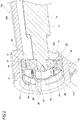
Fig. 2 is a cross-sectional diagram taken along the line a-a ofFig. 1 . -
Fig. 3 is a cross-sectional diagram illustrating an inner diameter side holder, an outer diameter side holder, and a housing, all of which are taken out. -
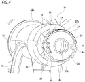
Fig. 4 is an enlarged perspective diagram of main parts illustrating a state in which the inner diameter side holder and the outer diameter side holder are not assembled to the housing. -
Fig. 5 is an enlarged perspective diagram of main parts illustrating the worm reduction gear according to the first embodiment of the present invention by omitting the housing. -
Fig. 6 is an enlarged perspective diagram of main parts illustrating a state in which the worm reduction gear according to the first embodiment of the present invention omits the housing and is viewed from a side opposite toFig. 5 in an axial direction. -
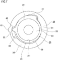
Fig. 7 is an end surface diagram illustrating a state in which the inner diameter side holder and the outer diameter side holder are taken out and viewed from a base end side of a worm. -
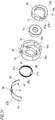
Fig. 8 is an enlarged perspective diagram of main parts illustrating a state in which members constituting the worm reduction gear of the first embodiment of the present invention are respectively disassembled. -
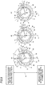
Figs. 9 is cross-sectional diagrams illustrating an abutting position of an outer circumferential surface of the inner diameter side holder and an inner circumferential surface of the outer diameter side holder. -
Figs. 10A to 10C are cross-sectional diagrams illustrating three examples of shapes of the outer circumferential surface of the inner diameter side holder and the inner circumferential surface of the outer diameter side holder. -
Fig. 11 is an end surface diagram illustrating a modified example of an inner circumferential surface of a holder holding part where an outer dimeter side cam part of the outer diameter side holder and a portion near one end in the circumferential direction abut on each other. -
Fig. 12A is a schematic cross-sectional diagram illustrating a direction of a meshing reaction force applied to the worm from a worm wheel when an electric motor is rotationally driven in a predetermined direction, andFig. 12B is a cross-sectional diagram taken along the line b-b ofFig. 12A . -
Fig. 13A is a schematic cross-sectional diagram illustrating a direction of a meshing reaction force applied to the worm from the worm wheel when the electric motor is rotationally driven in a direction opposite to the predetermined direction, andFig. 13B is a cross-sectional diagram taken along the line c-c ofFig. 13A . -
Fig. 14 is a diagram corresponding toFig. 13B illustrating a direction of a meshing reaction force in two directions applied to the worm from the worm wheel when the electric motor is rotationally driven in both directions. -
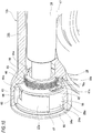
Fig. 15 is a partially cutting perspective diagram illustrating a worm reduction gear according to a second embodiment of the present invention. -
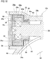
Fig. 16 is a cross-sectional diagram illustrating the worm reduction gear according to the second embodiment of the present invention. -
Fig. 17 is a perspective diagram illustrating an inner diameter side holder, an outer diameter side holder, a torsion coil spring, and a leaf spring, all of which are taken out. -
Figs. 18A to 18C are perspective diagrams illustrating a state in which the leaf spring is mounted on the outer diameter side holder. -
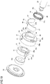
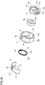
Fig. 19 is an enlarged perspective diagram of main parts illustrating a state in which members constituting the worm reduction gear according to the second embodiment of the present invention are respectively disassembled. -
Fig. 20 is a perspective diagram illustrating a housing taken out. -
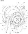
Fig. 21 is a perspective diagram illustrating a state in which a cover is removed. -
Fig. 22 is a perspective diagram illustrating an inner diameter side holder, an outer diameter side holder, and a torsion coil spring, all of which are taken out, according to a third embodiment of the present invention. -
Fig. 23 is a perspective diagram illustrating the outer diameter side holder taken out. -
Fig. 24 is a perspective diagram illustrating the torsion coil spring taken out. -
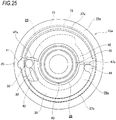
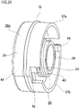
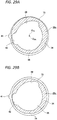
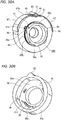
Fig. 25 is an end surface diagram illustrating a worm reduction gear according to a fourth embodiment of the present invention. -
Fig. 26 is a perspective diagram illustrating an inner diameter side holder, an outer diameter side holder, a torsion coil spring, and an O-ring, all of which are taken out. -
Fig. 27 is a perspective diagram illustrating the inner diameter side holder, the outer diameter side holder, and the torsion coil spring, all of which are taken out. -
Fig. 28 is a side surface diagram illustrating the outer diameter side holder. -
Figs. 29A and 29B are diagrams illustrating two examples of a cross-sectional shape taken along the line d-d ofFig. 28 . -
Fig. 30A is a perspective diagram illustrating an outer diameter side holder on which a leaf spring and a torsion coil spring are mounted in a worm reduction gear according to a fifth embodiment of the present invention, andFig. 30B is a perspective diagram of the outer diameter side holder when viewed from an opposite side toFig. 30A in an axial direction. -
Fig. 31 is an enlarged perspective diagram of main parts illustrating a state in which members constituting the worm reduction gear according to the fifth embodiment of the present invention are respectively disassembled. -
Fig. 32 is a perspective diagram illustrating an inner diameter side holder together with a bearing. -
Fig. 33 is an end surface diagram of the worm reduction gear illustrating a state in which a pin is inserted into a groove of the inner diameter side holder and a groove of the outer diameter side holder. -
Fig. 34 is the end surface diagram of the worm reduction gear illustrating a state in which the outer diameter side holder is held in a housing. -
Fig. 35A is a perspective diagram illustrating an outer diameter side holder on which a leaf spring and a torsion coil spring are mounted in a worm reduction gear according to a sixth embodiment of the present invention, andFig. 35B is a perspective diagram of the outer diameter side holder when viewed from an opposite side toFig. 35A in an axial direction. -
Fig. 36 is an enlarged perspective diagram of main parts illustrating a state in which members constituting the worm reduction gear according to the sixth embodiment of the present invention are respectively disassembled. -
Fig. 37 is a perspective diagram illustrating an inner diameter side holder together with a bearing. -
Fig. 38 is an end surface diagram of the worm reduction gear illustrating a state in which a pin is inserted into a groove of the inner diameter side holder and a groove of the outer diameter side holder. -
Fig. 39 is a partially cutting side surface diagram illustrating one example of a steering apparatus of a structure of a related art. -
Fig. 40 is an enlarged cross-sectional diagram taken along the line e-e ofFig. 39 . -
Figs. 1 to 9 illustrate a first embodiment of the present invention. A worm reduction gear of the embodiment is provided with ahousing 12a, aworm wheel 13, and aworm 14 in the same manner as those of aworm reduction gear 11 of a structure of a related art shown inFigs. 30A and 30B . Thehousing 12a includes awheel housing part 15 and aworm housing part 16a existing at a position twisted with respect to thewheel housing part 15 and having an intermediate part in the axial direction opened to the inside of thewheel housing part 15. An annular holding recessedpart 24 is provided on an inner circumferential surface of one end part in the axial direction (a left end part inFig. 2 ) of theworm housing part 16a. Further, the worm reduction gear of the embodiment will describe a case whereworm teeth 17 of theworm 14 is a right hand helix. - The
worm wheel 13 includeswheel teeth 48 on an outer circumferential surface, and is supported and fixed coaxially with thesteering shaft 5 at a portion near a front end of the steering shaft 5 (refer toFigs. 29A and 29B ), which is a driven shaft, rotatably supported at the inside of thewheel housing part 15. For example, theworm wheel 13 that is formed by connecting and fixing thewheel teeth 48 constituted of a synthetic resin around a disc-shaped member constituted of a metallic material can be used. Alternatively, thewhole worm wheel 13 may be constituted of a metallic material or a synthetic resin. - The
worm 14 is constituted of the metallic material and a based end part of theworm 14 is connected to an output shaft of theelectric motor 10 so as to be able to transmit torque in a state where theworm teeth 17 provided at the intermediate part in the axial direction is meshed with thewheel teeth 48. In theworm housing part 16a of thehousing 12a, theworm 14 is rotatably, supported and also displaceably supported with the base end part as a center. For this reason, a pair of rollingbearings worm teeth 17 in theworm 14 is sandwiched. Further, the pair of rollingbearings - A specific structure for supporting the
worm 14 rotatably, and also displaceably with the base end part as a center in theworm housing part 16 will be described with reference toFig. 40 which is related to a technology of the related art. Abearing fitting part 49 is provided at an opening part of theworm housing part 16a, and a housingside step part 50 directed to the other side in the axial direction is provided at one end part in the axial direction (a right end part inFig. 40 ) of thebearing fitting part 49. One side surface in the axial direction of anouter ring 51 constituting a rollingbearing 18b on a base end side abuts against the housingside step part 50, and an outer circumferential surface of theouter ring 51 is internally fitted to thebearing fitting part 49 by interference fitting. In the opening part of theworm housing part 16a, one side surface in the axial direction of a retainingring 52 locked to a portion adjacent to the other side in the axial direction of thebearing fitting part 49 abuts against the other side surface in the axial direction (a left side surface inFig. 40 ) of theouter ring 51. As a result, axial displacement of theouter ring 51 is restricted. Asmall diameter part 53 is provided at the base end part of theworm 14, and a wormside step part 54 directed to the other side in the axial direction is provided at one end part in the axial direction of thesmall diameter part 53. One side surface in the axial direction of aninner ring 57 constituting the rollingbearing 18b on the base end side abuts against the wormside step part 54 through anelastic body 55 such as a disc spring, and an inner circumferential surface of theinner ring 57 is externally fitted to thesmall diameter part 53 by clearance fitting. A tip surface (one side surface in the axial direction) of anut 56 screwed to the other end part in the axial direction of thesmall diameter part 53 abuts against the other side surface in the axial direction of theinner ring 57 through theelastic body 55. In other words, theinner ring 57 is elastically sandwiched between the wormside step part 54 and thenut 56 through the pair ofelastic bodies 55 in a state of being externally fitted to thesmall diameter part 53 with clearance fitting. Accordingly, the base end part of theworm 14 is supported with respect to the opening part of theworm housing part 16a through the rollingbearing 18b on the base end side. - However, a structure in which the
worm 14 is supported in theworm housing part 16a so as to be able to be shaken and displaced with the base end part as a center is not limited to the structure of the embodiment. That is, for example, theworm 14 can be configured so as to be able to be shaken and displaced with the base end part as a center by increasing an internal gap of the rollingbearing 18b on the base end side. Alternatively, a bearing may not be provided around the base end part of theworm 14, but the output shaft of theelectric motor 10 and the base end part of theworm 14 may be connected to each other via a joint provided with an elastic member which is elastically deformable in the diameter direction. - The tip part (the left end part in
Fig. 2 ) of theworm 14 is supported in the holding recessedpart 24 of theworm housing part 16a by the rollingbearing 18c on the tip side so as to be able to perform rotation and slight perspective movement with respect to theworm wheel 13. Specifically, the inner ring constituting the rollingbearing 18c on the tip side is externally fitted and fixed to the tip part of theworm 14 by the interference fitting. However, it is also possible to adopt a structure in which the inner ring of the rollingbearing 18c on the tip side is loosely and externally fitted to the tip part of theworm 14 so as not to be shaken in the diameter direction. On the other hand, an innerdiameter side holder 25, an outerdiameter side holder 26, aleaf spring 27 which is an elasticity imparting member in the diameter direction, and atorsion coil spring 28 which is the elastic urging member in the circumferential direction are provided between the outer ring of the rollingbearing 18c on the tip side and the holding recessedpart 24 of theworm housing part 16a. Further, the opening part on one side in the axial direction of the holding recessedpart 24 is closed by a disk-shaped cover (refer to acover 68 inFig. 19 ) after assembly is completed. - The inner
diameter side holder 25 is constituted of a synthetic resin such as PPS (polyphenylene sulfide), PA (polyamide), POM (polyacetal), or the like, or a light alloy such as an aluminum-based alloy or a magnesium-based alloy, or the like, and a whole structure thereof is formed in an approximately cylindrical shape. The innerdiameter side holder 25 is provided with a cylindrical holdermain body 29, and abearing holding part 30 for internally fitting and holding the outer ring constituting the rollingbearing 18c on the tip side is provided on an inner circumferential surface of the holdermain body 29. The inner diameter of thebearing holding part 30 is slightly smaller than the outer diameter of the outer ring of the rollingbearing 18c on the tip side, and the outer ring of the rollingbearing 18c on the tip side is internally fitted to thebearing holding part 30 by the interference fitting. However, the inner diameter of thebearing holding part 30 is set to be equal to or slightly larger than the outer diameter of the outer ring of the rollingbearing 18c on the tip side, such that the outer ring of the rollingbearing 18c on the tip side can be configured to be loosely and internally fitted and held so as not to be shaken in the diameter direction with respect to thebearing holding part 30. - With respect to a first direction D1 (an up-and-down direction in
Figs. 1 ,3 ,7 , and9 ) orthogonal to a center axis of theworm wheel 13 and a center axis of theworm 14, among the outer circumferential surfaces of the holdermain body 29, an inner diameterside cam part 31 constituting an inner diameter side curved surface part of the present invention, an outer diameter of which becomes larger as moving toward one circumferential direction (a front in a clockwise direction inFigs. 1 ,3 ,7 , and9 ) with respect to a center of the rollingbearing 18c, that is, a center axis O14 of theworm 14, is provided at a portion (an upper part inFigs. 1 ,3 ,7 , and9 ) positioned on a side far from a meshing part between theworm teeth 17 and thewheel teeth 48. In other words, thickness (thickness in the diameter direction) of a half part on the side opposite to the side of the worm wheel 13 (an upper half part inFigs. 1 ,3 ,7 , and9 ) in the first direction D1 of the holdermain body 29 becomes larger as moving toward a portion near one end in the circumferential direction from the other end in the circumferential direction (a rear end part in the clockwise direction inFig. 1 ), and the inner diameterside cam part 31 is provided on the outer circumferential surface of the portion. - Further, a
portion 80 positioned on the side opposite to the inner diameterside cam part 31 is formed on a compound curved surface where a plurality of curved surfaces having different radii of curvature from each other are smoothly continued among the outer circumferential surfaces of the holdermain body 29 in the first direction D1, with respect to theportion 80 near one end in the circumferential direction of the outer circumferential surface of the half part on the side far from the meshing part between theworm teeth 17 and thewheel teeth 48, in other words, with respect to the side far from the meshing part between thewheel teeth 48 and theworm teeth 17, and a surface P passing through the center axis of theworm wheel 13 and the center axis of theworm 14. - A protruding
part 32 protruding outwards in the diameter direction is provided at a portion adjacent to the other side in the circumferential direction of the inner diameterside cam part 31 among the outer circumferential surfaces of the holdermain body 29, and a displacementside pin part 33 protruding in the axial direction is provided on one side surface in the axial direction of the protruding part 32 (a left side surface inFig. 2 ). - The outer
diameter side holder 26 is constituted of a synthetic resin such as PPS (polyphenylene sulfide), PA (polyamide), POM (polyacetal), or the like, or a light alloy such as an aluminum-based alloy, a magnesium-based alloy, or the like, and is provided with an approximately cylindrical outer diameter sidecylindrical part 34, and aside plate part 35, an inner diameter sidecylindrical part 36, and a pair of protrudingpiece parts cylindrical part 34 is approximately cylindrical shape, and aholder holding part 38 is provided on the inner diameter side thereof. Theholder holding part 38 serves to hold the innerdiameter side holder 25 so as to be able to be shaken with the center axis of theworm 14 as a center and to be displaced in the first direction D1. An outer diameterside cam part 39 constituting an outer diameter side curved surface part of the present invention, in which the inner diameter thereof becomes larger as moving toward one circumferential direction with respect to the center of the rollingbearing 18c, that is, the center axis O14 of theworm 14, and the curvature of the inner diameter thereof is smaller than the curvature of the outer diameter of the inner diameterside cam part 31, is provided at a portion facing the inner diameterside cam part 31 among the inner circumferential surfaces of theholder holding part 38. In other words, the outer diameterside cam part 39 is provided on the inner circumferential surface of the portion in which thickness of the half part on the side far from the meshing part in the first direction D1 becomes smaller as moving from the other end part in the circumferential direction toward a portion near the one end in the circumferential direction in the outer diameter sidecylindrical part 34. In the embodiment, the inner diameterside cam part 31 is constituted of the compound curved surface where the plurality of curved surfaces having different radii of curvature from each other are smoothly continued, and the outer diameterside cam part 39 is constituted of a single partial cylindrical surface. - Further, for the outer
diameter side holder 26 the same material as that of the innerdiameter side holder 25 may be used, or different material may be used. - Further, an inner
circumferential surface 81 that is constituted of a single partial cylindrical surface is formed at a position facing theportion 80 near one end in the circumferential direction of the holdermain body 29 among the inner circumferential surfaces of theholder holding part 38. The innercircumferential surface 81 is positioned on the side opposite to the outer diameterside cam part 39 with respect to the side far from the meshing part between thewheel teeth 48 and theworm teeth 17, and the surface P passing through the center axis of theworm wheel 13 and the center axis of theworm 14. - A recessed
part 40 that is recessed outwards in the diameter direction is provided on a portion adjacent to the other side in the circumferential direction of the outer diameterside cam part 39 among the inner circumferential surfaces of theholder holding part 38 in a state of being elongated in the circumferential direction. The protrudingpart 32 is disposed at the inside of the recessedpart 40 in a state where the innerdiameter side holder 25 is internally fitted and held at the inside of theholder holding part 38. Accordingly, thediameter side holder 25 can be slightly shaken and displaced with the center axis of theworm 14 as a center. A portion deviated from the outer diameterside cam part 39 and the recessedpart 40 on the inner circumferential surfaces of theholder holding part 38 has an approximately elliptical shape which is elongated in the first direction D1 when viewed from the axial direction. Accordingly, the innerdiameter side holder 25 is internally fitted and held in theholder holding part 38 so as to be able to be shaken with the center axis of theworm 14 as a center and to be displaced in the first direction D1 within a range where the protrudingpart 32 can move in the recessedpart 40. - In the embodiment, as illustrated in
Fig. 9 , an abutting part (sliding contact part) between the inner circumferential surface of theholder holding part 38 and the outer circumferential surface of the innerdiameter side holder 25 is provided at two positions. That is, an approximately center position in the circumferential direction of the inner diameterside cam part 31 abuts on the outer diameterside cam part 39. Additionally, theportion 80 near one end in the circumferential direction of the outer circumferential surface of the half part on the side far from the meshing part between theworm teeth 17 and thewheel teeth 48 in the first direction D1 in the innerdiameter side holder 25 abuts on the innercircumferential surface 81 of theholder holding part 38. An abutting part between theportion 80 near one end in the circumferential direction and the innercircumferential surface 81 of theholder holding part 38 is positioned on the side opposite to an abutting part between the inner diameterside cam part 31 and the outer diameterside cam part 39 with respect to the side far from the meshing part between thewheel teeth 48 and theworm teeth 17, and the surface P passing through the center axis of theworm wheel 13 and the center axis of theworm 14. - Further, the above-mentioned two abutting parts are provided so that directions of meshing reaction forces fr1 and fr2 applied to the
worm 14 from the meshing parts when theworm wheel 13 rotates in both directions are positioned in a region X of an inferior angle formed by two lines connected to the center axis O14 of theworm 14. - The region X is positioned on the side far from the meshing part between the
worm teeth 17 and thewheel teeth 48 in the first direction D1. - Further, the meshing reaction forces fr1 and fr2 are forces generated at the tip part of the
worm 14 based upon the meshing reaction forces acting on the meshing part between theworm teeth 17 and thewheel teeth 48. - Further, as illustrated in
Figs. 9A to 9C , the abutting parts at two positions are formed so as to satisfy a relationship with the directions of the meshing reaction forces fr1 and fr2 regardless of the circumferential position of the innerdiameter side holder 25 with respect to the outerdiameter side holder 26. - Further, in the embodiment, the
portion 80 near one end in the circumferential direction with respect to the inner diameterside cam part 31 of the innerdiameter side holder 25 is formed on the compound curved surface where the plurality of curved surfaces having different radii of curvature from each other are smoothly continued, and the innercircumferential surface 81 of theholder holding part 38 on which theportion 80 near one end in the circumferential direction abuts is constituted by the single partial cylindrical surface. - That is, in the embodiment, the outer diameter
side cam part 39 and the innercircumferential surface 81 of theholder holding part 38 are constituted by the single partial cylindrical surface, and the inner diameterside cam part 31 and theportion 80 near one end in the circumferential direction are constituted by the compound curved surface where the plurality of curved surfaces having different radii of curvature from each other are smoothly continued. - Further, the
portion 80 near one end in the circumferential direction of the innerdiameter side holder 25 constitutes another inner diameter side curved surface part of the present invention; the innercircumferential surface 81 of theholder holding part 38 on which theportion 80 near one end in the circumferential direction abuts constitutes another outer diameter side curved surface part of the present invention; and theportion 80 near one end in the circumferential direction of the innerdiameter side holder 25 and the innercircumferential surface 81 of theholder holding part 38 constitute the other abutting part of the present invention. - In the embodiment, gaps between virtual straight lines β1 and β2 orthogonal to the directions of meshing reaction forces fr1 and fr2 and tangent lines γ1 and γ2 of the inner circumferential surface of the
holder holding part 38 at the abutting part with the outer circumferential surface of the innerdiameter side holder 25 become wider as moving toward a front side in a rotating direction of the innerdiameter side holder 25. That is, when theworm wheel 13 rotates in one direction, a gap between the virtual straight line β1 orthogonal to the direction of the meshing reaction force fr1 applied to the tip part of theworm 14 and the tangent γ1 of the outer diameterside cam part 39 at the abutting part with the inner diameterside cam part 31 becomes wider as moving toward the other circumferential direction (a lower left side inFig. 9 ). On the other hand, when theworm wheel 13 rotates in the other circumferential direction, a gap between the virtual straight line β2 orthogonal to the direction of the meshing reaction force fr2 applied to the tip part of theworm 14 and the tangent γ2 of the inner circumferential surface of theholder holding part 38 at the butting part with the innerdiameter side holder 25 becomes wider as moving toward one circumferential direction (a lower right side inFig. 9 ). Specifically, shapes of the innerdiameter side holder 25 and the outerdiameter side holder 26 are restricted so that angles θ1 and θ2 formed between the virtual straight lines β1 and β2 and the tangent lines γ1 and γ2 become about 5° to about 30°. - Further,
Fig. 9 illustrates a state in which the innerdiameter side holder 25 rotates in the other circumferential direction (a counterclockwise direction shown inFig. 9 ) in the order of Section (A) → Section (B) → Section (C). Accordingly, even when the innerdiameter side holder 25 rotates in the other circumferential direction, respective phases of the abutting part between the inner diameterside cam part 31 and the outer diameterside cam part 39, and another abutting part between theportion 80 near one end in the circumferential direction of the innerdiameter side holder 25 and the innercircumferential surface 81 of theholder holding part 38 are almost not changed. In this case, the innerdiameter side holder 25 and the rollingbearing 18c held in the innerdiameter side holder 25 are not substantially moved in the left-and-right direction inFig. 9 , but are displaced downward, that is, displaced only toward the side of theworm wheel 13 in the first direction D1. Therefore, such displacement is caused by shapes of the inner diameterside cam part 31, the outer diameterside cam part 39, theportion 80 near one end in the circumferential direction of the innerdiameter side holder 25, and the innercircumferential surface 81 of theholder holding part 38. - Additionally, in the case of the parts providing such displacement, the shapes of the inner diameter
side cam part 31, the outer diameterside cam part 39, theportion 80 near one end in the circumferential direction of the innerdiameter side holder 25, and the innercircumferential surface 81 of theholder holding part 38 are not limited. For example, the inner diameterside cam part 31 and theportion 80 near one end in the circumferential direction of the innerdiameter side holder 25 can be formed as a single partial cylindrical surface, and the outer diameterside cam part 39 and the innercircumferential surface 81 of theholder holding part 38 can be constituted by a compound curved surface where the plurality of curved surfaces having different radii of curvature from each other are smoothly continued. Alternatively, all of the inner diameterside cam part 31, the outer diameterside cam part 39, theportion 80 near one end in the circumferential direction of the innerdiameter side holder 25, and the innercircumferential surface 81 of theholder holding part 38 may be constituted by the compound curved surface. - Further, in the embodiment, a cross-sectional shape (a bus line shape) in the axial direction of the inner circumferential surface of the
holder holding part 38 and the outer circumferential surface of the innerdiameter side holder 25 is a linear shape as illustrated inFig. 10A . However, as illustrated inFig. 10B , the bus line shape of the outer circumferential surface of the innerdiameter side holder 25 can be a partially circular arc shape in which the intermediate part in the axial direction is curved in a direction of protruding outwards in the diameter direction, and thus sliding friction between the inner circumferential surface of theholder holding part 38 and the outer circumferential surface of the innerdiameter side holder 25 can be also reduced. Alternatively, as illustrated inFig. 10C , the bus line shape of the outer circumferential surface of the innerdiameter side holder 25 may be the partially circular arc shape in which the intermediate part in the axial direction is curved in the direction of protruding outwards in the diameter direction, and the bus line shape of the inner circumferential surface of theholder holding part 38 may be a partially circular arc shape in which the intermediate part in the axial direction is curved in a direction of being recessed inwards in the diameter direction. When the bus line shapes of the inner circumferential surface of theholder holding part 38 and the outer circumferential surface of the innerdiameter side holder 25 are formed as illustrated inFig. 10C , the innerdiameter side holder 25 and the outerdiameter side holder 26 can be prevented from shifting in the axial direction. - Further, as illustrated in a modified example of
Fig. 11 , on the inner circumferential surface of theholder holding part 38 of the outerdiameter side holder 26, circular-arc shaped protrudingparts side cam part 31 of the innerdiameter side holder 25 abuts, and a portion on which theportion 80 near one end in the circumferential direction abuts. In this case, when the innerdiameter side holder 25 rotates in the other circumferential direction (the counterclockwise direction shown inFig. 9 ), respective phases of an abutting part between the inner diameterside cam part 31 and the circular-arc shaped protrudingpart 39a, and the other abutting part between theportion 80 near one end in the circumferential direction of the innerdiameter side holder 25 and the circular-arc shaped protrudingpart 81a of theholder holding part 38 are almost not changed. - That is, in this example, the inner
diameter side holder 25 has the inner diameterside cam part 31 constituting the inner diameter side curved surface part of the present invention in the same manner as that of the embodiment, and on the other hand, when the innerdiameter side holder 25 rotates in the circumferential direction with respect to the outerdiameter side holder 26, the circular-arc shaped protrudingpart 39a constituting the outer diameter side curved surface part of the present invention in contact with the inner diameterside cam part 31 is provided at a portion opposite to the inner diameterside cam part 31 among the inner circumferential surfaces of theholder holding part 38 of the outerdiameter side holder 26. - An
engagement protruding part 41 protruding outwards in the diameter direction is provided at one position in the circumferential direction among the outer circumferential surfaces of the outer diameter sidecylindrical part 34. - A
side plate part 35 having an approximately annular plate shape is provided in a state of being bent inwards in the diameter direction from one side edge in the axial direction of the outer diameter sidecylindrical part 34. A partial circular-arc shaped throughhole 42 for inserting the displacementside pin part 33 of the innerdiameter side holder 25 is provided at one position in the circumferential direction aligned with the recessedpart 40 among portions near an outer diameter of theside plate part 35. A tip part of the displacementside pin part 33 protrudes from one side surface in the axial direction of theside plate part 35 through the throughhole 42 in a state where the innerdiameter side holder 25 is internally fitted and held in theholder holding part 38. - The inner diameter side
cylindrical part 36 having an approximately cylindrical shape is provided in a state of being bent toward one side in the axial direction from an inner circumferential edge of theside plate part 35. Apositioning protruding part 43 protruding outwards in the diameter direction is provided at a portion where a phase in the circumferential direction coincides with the meshing part among the outer circumferential surfaces of the inner diameter sidecylindrical part 36. - The pair of protruding
piece parts side plate part 35. In other words, a cylindrical part is provided in a state of protruding toward one side in the axial direction at the outer circumferential edge part of one side surface in the axial direction of theside plate part 35. Among the cylindrical parts, notch parts are provided at two positions on the opposite sides with respect to a second direction D2 (a left-and-right direction inFigs. 1 ,3 ,7 , and9 ) which is parallel to the center axis of theworm wheel 13 and orthogonal to the center axis of theworm 14, and the pair of protrudingpiece parts piece part 37a (an upper side inFig. 1 ) of the pair of protrudingpiece parts cylindrical part 34 by the thickness of theleaf spring 27 or more. On the other hand, the outer diameter of the other protrudingpiece part 37b (a lower side inFig. 1 ) of the pair of protrudingpiece parts cylindrical part 34. That is, the outer circumferential surface of the other protrudingpiece part 37b and the outer circumferential surface of the outer diameter sidecylindrical part 34 exist on the same cylindrical surface. Apedestal part 44 bent inwards in the diameter direction is provided at the other end part in the circumferential direction of the other protrudingpiece part 37b. - The outer
diameter side holder 26 is internally fitted to the holding recessedpart 24 of theworm housing part 16a in a state where the displacement in the first direction D1 and the second direction D2 is possible and the rotation with respect to theworm housing part 16a is substantially inhibited to a degree that the displacement in the first direction D1 and the second direction D2 is not disturbed. A gap for allowing the displacement of the outerdiameter side holder 26, based upon the meshing reaction forces applied to theworm 14 during the operation of the worm reduction gear at opposite side portions in the second direction D2 and the end part on the side far from the meshing part between theworm teeth 17 and thewheel teeth 48 in the first direction D1 is provided between the outer circumferential surface of the outerdiameter side holder 26 and the inner circumferential surface of the holding recessedpart 24. Specifically, a shape of the holding recessedpart 24 when viewed from the axial direction is an elliptical shape or an oval shape in which a long diameter thereof coincides with the first direction D1 and a short diameter thereof coincides with the second direction D2. The short diameter becomes larger than an outer diameter of an outer circumferential surface of a portion deviated from theengagement protruding part 41 in the outerdiameter side holder 26. However, the shape of the holding recessedpart 24 when viewed from the axial direction can be a circular shape, the inner diameter of which is larger than the outer diameter of the outer circumferential surface of the portion deviated from theengagement protruding part 41 in the outerdiameter side holder 26. An engagement recessedpart 45 recessed outwards in the diameter direction is provided at one position in the circumferential direction of the holding recessedpart 24. The engagement recessedpart 45 and theengagement protruding part 41 of the outerdiameter side holder 26 are loosely engaged with each other, thereby substantially preventing the rotation of the outerdiameter side holder 26 with respect to theworm housing part 16a. - The
leaf spring 27 is formed by bending an elastic metal plate into a partial cylindrical shape, and is sandwiched between the holding recessedpart 24 and the outer circumferential surface of one protrudingpiece part 37a in a state of being elastically compressed in the diameter direction of the rollingbearing 18c on the tip side. That is, opposite ends in the circumferential direction of theleaf spring 27 are elastically pressed against the inner circumferential surface of the holding recessedpart 24, and the center part in the circumferential direction of theleaf spring 27 is elastically pressed against the outer circumferential surface of one protruding piece part 37. Accordingly, when the tip part of theworm 14 is displaced in a direction separating from theworm wheel 13 in the first direction D1 based upon the meshing reaction force applied to theworm 14 from the meshing part betweenworm teeth 17 and thewheel teeth 48, a force (elasticity) that elastically presses the tip part of theworm 14 in the first direction D1, that is, toward theworm wheel 13 in a far and near moving direction of theworm wheel 13 is imparted to the tip part of theworm 14 by theleaf spring 27. Further, a spring constant of theleaf spring 27 is set to be sufficiently small. - In the worm reduction gear of the embodiment, a meshing reaction force is not applied to the
worm 14 from the meshing part between theworm teeth 17 and thewheel teeth 48, that is, an assembly position of the outerdiameter side holder 26 with respect to the holding recessedpart 24 is adjusted so that the outer circumferential surface of the outerdiameter side holder 26 and the inner circumferential surface of the holding recessedpart 24 abuts on a portion (lower end parts inFigs. 1 and3 ) where a phase in the circumferential direction coincides with the meshing part in a state where theelectric motor 10 is not rotationally driven. - A
torsion coil spring 28 is formed by bending and molding a metal wire, and includes acoil part 46 and a pair ofarm parts cylindrical part 36 of the outerdiameter side holder 26 is inserted through thecoil part 46. Onearm part 47a of the pair ofarm parts side pin part 33 of the innerdiameter side holder 25, and theother arm part 47b is pressed against the other side surface in the circumferential direction of thepedestal part 44 of the other protrudingpiece part 37b. When the displacementside pin part 33 is elastically pressed in the other circumferential direction by onearm part 47a, the innerdiameter side holder 25 is elastically urged against the outerdiameter side holder 26 in a direction of rotating in the other circumferential direction. An elastic force in the direction of rotating the innerdiameter side holder 25 in the other circumferential direction with respect to the outerdiameter side holder 26 is converted into a force which elastically presses the innerdiameter side holder 25 and the tip part of theworm 14 against the side of theworm wheel 13 in the diameter direction by the engagement between the inner diameterside cam part 31 of the innerdiameter side holder 25 and the outer diameterside cam part 39 of the outerdiameter side holder 26. That is, when the innerdiameter side holder 25 rotates in the other circumferential direction with respect to the outerdiameter side holder 26, and a portion where the outer diameter of the inner diameterside cam part 31 is large abuts on a portion where the inner diameter of the outer diameterside cam part 39 is small, the innerdiameter side holder 25 is pressed against the side of theworm wheel 13 in the first direction D1. Further, in a state where thetorsion coil spring 28 applies elasticity, a tip part of thepositioning protruding part 43 of the inner diameter sidecylindrical part 36 abuts on the inner circumferential surface of thecoil part 46. In other words, the abutting part between the outer circumferential surface of the inner diameter sidecylindrical part 36 and the inner circumferential surface of thecoil part 46 is determined to be positioned by thepositioning protruding part 43 provided on the inner diameter sidecylindrical part 36. - In the embodiment, a right-handed twisted one is used for the
worm teeth 17, a right-handed winding one is used as thetorsion coil spring 28, and a rotating direction of the innerdiameter side holder 25 is the counterclockwise direction inFigs. 1 ,3 ,7 and9 . However, a twisting direction of theworm teeth 17, a winding direction of thetorsion coil spring 28, and the rotating direction of the innerdiameter side holder 25 can be designed by combining the respective arbitrary directions. - Further, in the embodiment, the elasticity of the
torsion coil spring 28 is adjusted so that meshing resistance at the meshing part between theworm teeth 17 and thewheel teeth 48 does not become excessively large, and thus a force for elastically pressing the tip part of theworm 14 against the side of theworm wheel 13 in the first direction D1 is sufficiently reduced based upon the elasticity of thetorsion coil spring 28. - In the worm reduction gear of the embodiment, the inner diameter
side cam part 31, the outer diameter of which becomes larger as moving toward one circumferential direction is provided at a portion positioned on the side far from the meshing part between theworm teeth 17 and thewheel teeth 48 in the first direction D1 on the outer circumferential surface of the innerdiameter side holder 25. Further, the outer diameterside cam part 39, the inner diameter of which becomes larger as moving toward one circumferential direction, and the curvature of the inner diameter of which is smaller than the curvature of the outer diameter of the inner diameterside cam part 31, is provided at a portion facing the inner diameterside cam part 31 on the inner circumferential surface of the outerdiameter side holder 26. Accordingly, thetorsion coil spring 28 is capable of converting a force which elastically urges the innerdiameter side holder 25 against the outerdiameter side holder 26 in a direction of rotating in the other side circumferential direction into a force which elastically urges the innerdiameter side holder 25 and the tip part of theworm 14 against the side of theworm wheel 13 in the first direction D1. Accordingly, a backlash at the meshing part between theworm teeth 17 and thewheel teeth 48 can be suppressed, and a variation of a meshing position between theworm teeth 17 and thewheel teeth 48 can be suppressed regardless of the dimensional errors and assembly errors of the respective members constituting the worm reduction gear, and wear of the teeth surfaces of thewheel teeth 48 and theworm teeth 17. That is, when the dimensional errors and assembly errors occur at the respective members constituting the worm reduction gear, and the teeth surfaces of thewheel teeth 48 and theworm teeth 17 are worn out, the innerdiameter side holder 25 is displaced in the first direction D1 based upon the elasticity of thetorsion coil spring 28, and thus a deviation of the meshing position between thewheel teeth 48 and theworm teeth 17 is corrected. Therefore, in the worm reduction gear of the embodiment, even though dimensional accuracy and assembly accuracy of the respective members constituting the worm reduction gear are not particularly high, the above-mentioned dimensional errors and assembly errors can be effectively absorbed, thereby suppressing the variation of the meshing position between theworm teeth 17 and thewheel teeth 48, and further, even when the teeth surfaces of thewheel teeth 48 are worn out, the variation of the meshing position is prevented. As a result, it is possible to effectively prevent generation of a teeth striking sound at the meshing part between theworm teeth 17 and thewheel teeth 48. - Meanwhile, in a structure of the related art shown in
Fig. 40 , in order to adjust a force which elastically presses the tip part of theworm 14 against the side of theworm wheel 13 in the direction orthogonal to the center axis of theworm wheel 13 and the center axis of theworm 14 to an appropriate magnitude by thetorsion coil spring 23, it is necessary to sufficiently secure the dimensional accuracy and assembly accuracy of the respective members constituting theworm reduction gear 11, and thus the manufacturing cost of theworm reduction gear 11 may increase. That is, in theworm reduction gear 11 in the related art, theholder 19 is press-fitted into the inside of theworm housing part 16 of thehousing 12, and the outer ring of the rollingbearing 18a on the tip side is press-fitted into theholder 19. The inner ring of the rollingbearing 18a on the tip side is externally fitted into thebush 21 without a gap, and thebush 21 is externally fitted into thelarge diameter part 20 of theworm 14 through a minute gap in the diameter direction. Thetorsion coil spring 23 is provided between thepreload pad 22 which is press-fitted into the tip part of theworm 14 and theholder 19. The tip part of theworm 14 is elastically pressed against the side of theworm wheel 13 in the first direction D1 by thetorsion coil spring 23, whereby the backlash is suppressed. Accordingly, when a dimension in the diameter direction of the minute gap in the diameter direction varies due to the dimensional errors and assembly errors of the respective members constituting theworm reduction gear 11, there exists a possibility that the force elastically pressing the tip part of theworm 14 against the side of theworm wheel 13 cannot be adjusted to the appropriate magnitude. - In the worm reduction gear of the present invention, provided are gaps for allowing the outer
diameter side holder 26 to be displaced based upon the meshing reaction force applied to theworm 14 during the operation of the worm reduction gear at the opposite side portions in the second direction D2 and the end part on the side far from the meshing part between theworm teeth 17 and thewheel teeth 48 in the first direction D1 between the outer circumferential surface of the outerdiameter side holder 26 and the inner circumferential surface of the holding recessedpart 24. Therefore, when the meshing reaction force is applied to theworm 14 from the meshing part between theworm teeth 17 and thewheel teeth 48 during the operation of the worm reduction gear, the tip part of theworm 14 is displaced in the direction separating from theworm wheel 13 in the first direction D1 while elastically pressing theleaf spring 27, based upon the existence of the gap at the portion positioned at the end part on the side far from the meshing part in the first direction out of the above-mentioned gaps. Accordingly, a meshing state between thewheel teeth 48 and theworm teeth 17 is appropriately maintained. Further, in the embodiment, theleaf spring 27 is sandwiched between the outer circumferential surface of one protrudingpiece part 37a and the inner circumferential surface of the holding recessedpart 24. Therefore, when the operation of the worm reduction gear is stopped and the meshing reaction force is not applied to theworm 14 from the meshing part, theworm 14 is pressed against the side of theworm wheel 13 in the first direction D1 by theleaf spring 27, whereby theworm 14 returns to an original position. That is, the outer circumferential surface of the outerdiameter side holder 26 and the inner circumferential surface of the holding recessedpart 24 abut on each other at a portion where the phase in the circumferential direction coincides with the meshing part between theworm teeth 17 and thewheel teeth 48. Accordingly, out of the above-mentioned gaps, the gap at the portion positioned at the end part on the side far from the meshing part in the first direction D1 can be maintained for a long period of time. - Further, an amount in which the tip part of the
worm 14 can be displaced in the first direction D1 depends on a gap dimension in the diameter direction at the portion positioned at the end part on the side far from the meshing part between theworm 17 and thewheel teeth 48 in the first direction D1, out of the gaps between the outer circumferential surface of one protrudingpiece part 37a and the inner circumferential surface of the holding recessedpart 24. As described in the structure of the related art shown inFig. 40 , management (adjustment) of the dimension in the diameter direction can be easily performed in comparison with a case in which a size of the minute gap provided over the entire periphery between the outer circumferential surface of thelarge diameter part 20 and the inner circumferential surface of thebush 21 is managed. That is, in the structure of the related art, when the meshing position between theworm teeth 17 and thewheel teeth 48 varies based upon the dimensional errors and the assembly errors of theworm 14 and theworm wheel 13, or the assembly error of theholder 19 with respect to thehousing 12 becomes large, there exists a possibility that it becomes difficult to secure the dimension of the minute gap in the diameter direction at the portion positioned at the end part on the side far from the meshing part between theworm teeth 17 and thewheel teeth 48 in the first direction D 1, out of the above-mentioned minute gaps. On the other hand, in the embodiment, securing the dimension of the gap in the diameter direction at the portion positioned at the end part on the side far from the meshing part between thewheel teeth 48 and theworm teeth 17 in the first direction D1 out of the above-mentioned minute daps can be achieved by adjusting the assembly position of the outerdiameter side holder 26 with respect to the holding recessedpart 24. Accordingly, it is relatively easy to secure an amount displacement of the tip end part of theworm 14 in the first direction D 1, such that an increase in the manufacturing cost of the worm reduction gear can be suppressed. - In the embodiment, since the spring constant of the
leaf spring 27 is sufficiently small, a change of the meshing resistance in the meshing part can be reduced regardless of a change in a distance between the center axes of theworm wheel 13 and theworm 14 caused by rotating speed of theworm wheel 13 and theworm 14, a magnitude of the torque transmitted from the meshing part between theworm teeth 17 and thewheel teeth 48, and a temperature change inside thehousing 12a. - In the embodiment, the gaps between the virtual straight lines β1 and β2 orthogonal to the directions of the meshing reaction forces fr1 and fr2 and the tangent lines γ1 and γ2 on the inner circumferential surface of the
holder holding part 38 at the abutting part with the outer circumferential surface of the innerdiameter side holder 25 becomes wider as moving toward the front side in the rotating direction of the innerdiameter side holder 25. Therefore, out of the forces in which the tip part of theworm 14 is elastically pressed against the side of theworm wheel 13 in the first direction D1, even though the force based upon the elasticity of thetorsion coil spring 28 is smaller than the force based upon the elasticity of theleaf spring 27, the innerdiameter side holder 25 is prevented from rotating in one circumferential direction with respect to the outerdiameter side holder 26 by the meshing reaction forces fr1 and fr2. In short, a change in a meshing distance based upon the meshing reaction forces fr1 and fr2 is absorbed only by elastic deformation of theleaf spring 27, such that thetorsion coil spring 28 can be prevented from elastically being deformed by the change in the distance. - In the embodiment, the inner diameter
side cam part 31 is provided on the outer circumferential surface of the innerdiameter side holder 25, and the outer diameterside cam part 39 is provided on the inner circumferential surface of theholder holding part 38. Therefore, the outer circumferential surface of the innerdiameter side holder 25 and the inner circumferential surface of theholder holding part 38 abut on each other (sliding contact) at two positions on both sides sandwiching a virtual plane α (refer toFig. 1 ) including the meshing part between theworm teeth 17 and thewheel teeth 48 and the center axis of theworm 14. In particular, in the worm reduction gear, the abutting part (sliding contact) between the inner circumferential surface of theholder holding part 38 and the outer circumferential surface of the innerdiameter side holder 25 is provided so that the directions of the meshing reaction forces fr1 and fr2 applied to theworm 14 are positioned in a region X of an inferior angle formed by two lines connected to the center axis O14 of theworm 14. Accordingly, when the meshing reaction forces fr1 and fr2 are inputted, the reaction forces can be always received by the abutting parts at the two positions. Meanwhile, when the meshing reaction forces fr1 and fr2 exist outside the region X, the reaction forces are received only by the abutting part at one position, and thus one abutting part and the other abutting part are separated from each other. - Accordingly, the meshing reaction forces fr1 and fr2 are surely transmitted to the outer
diameter side holder 26 regardless of the rotating direction of theworm 14, whereby the meshing reaction forces fr1 and fr2 can be supported more effectively by thehousing 12a through the outerdiameter side holder 26 and theleaf spring 27. Further, a component in the first direction D1 orthogonal to the center axis of theworm wheel 13 and the center axis of theworm 14 as well as a component in the second direction D2 orthogonal to the first direction D1 are included in the meshing reaction force applied to theworm 14 from the meshing part between theworm teeth 17 and thewheel teeth 48. What is described above will now be hereinafter described with reference toFigs. 12A to 14 . - The
worm teeth 17 of theworm 14 are spirally formed on the outer circumferential surface of the intermediate part in the axial direction of theworm 14. Therefore, when theworm 14 is rotated and driven and a driving force is transmitted from theworm 14 to theworm wheel 13, the meshing reaction forces including components in three directions of x, y, and z inFigs. 12A to 13B are applied to theworm 14 from theworm wheel 13. In the cases shown inFigs. 12A to 13B , the magnitudes of the driving forces applied to theworm 14 are the same as each other, but action directions of the driving forces, that is, the rotating directions of theworm 14, are opposite to each other. Therefore, theworm wheels 13 in the cases shown inFigs. 12A to 13B are rotated in mutually opposite directions. When theworm 14 is rotated and driven, apparent meshing reaction forces having component forces of Fx, Fy, and Fz which are components in three directions of x, y, and z inFigs. 12A to 13B are respectively applied to theworm 14 from theworm wheel 13 at the meshing part between thewheel teeth 48 and theworm teeth 17. The components Fx and Fz among the components Fx, Fy, and Fz become opposite to each other in direction between a case in which theworm wheel 13 rotates in one direction (a direction indicated by an arrow mark A inFig. 12A ) as illustrated inFigs. 12A and 12B , and a case in which theworm wheel 13 rotates in the other direction (a direction indicated by an arrow mark B inFig. 13A ) as illustrated inFigs. 13A and 13B . - On the other hand, when a distance between the meshing part between the
worm teeth 17 and thewheel teeth 48 and a swing center o of theworm 14 in the diameter direction of theworm 14 is defined as d14, moment M having a magnitude of d14·Fx acts on theworm 14. Therefore, when a distance between the meshing part and the swing center o in the axial direction of theworm 14 is defined as L14, a force Fr having a magnitude of M/L14 based upon the moment M acts on theworm 14 in the diameter direction (an upper direction inFigs. 12A and 12B and a lower direction inFigs. 13A and 13B ). The acting directions of the forces Fr are opposite to each other in the cases shown inFigs. 12A to 13B . Therefore, as illustrated inFigs. 12A and 12B , when theworm wheel 13 rotates in one direction, a magnitude of an actual force Fy' in a y-direction considering the moment M, which acts on theworm 14 from theworm wheel 13 at the meshing part between theworm teeth 17 and thewheel teeth 48, becomes Fy'=Fy-Fr and thus becomes small, whereby as illustrated inFigs. 13A and 13B , when theworm wheel 13 rotates in the other direction, the magnitude thereof becomes Fy' = Fy + Fr, and thus becomes large. Accordingly, when theworm wheel 13 rotates in one direction, an actual resultant force F' of the meshing component force in the y and z directions acting on the meshing part becomes small as illustrated by an arrow mark C inFig. 14 , and when theworm wheel 13 rotates in the other direction, the resultant force F' thereof becomes large as illustrated by an arrow mark D inFig. 14 . As can be seen from the direction of the resultant force F', even when theworm wheel 13 rotates in any direction, it is found out that the components with respect to the first direction D1 (an up-and-down direction inFigs. 12A to 13B ) and the second direction D2 (a front and rear direction inFigs. 12A and13A , and a left-and-right direction inFigs. 12B ,13B , and14 ) are included in the meshing reaction force applied to theworm 14 from the meshing part. - The above-mentioned meshing reaction forces fr1 and fr2 are forces generated at the tip part of the
worm 14 based upon the meshing reaction force F' at the meshing part between theworm teeth 17 and thewheel teeth 48 indicated by the arrow marks C and D. - Further, when the
worm wheel 13 rotates in one direction, the component force in a virtual plane orthogonal to the center axis of theworm 14 among the meshing reaction forces applied to theworm 14 from the meshing part, for example, 14 acts in the direction of 90° to 135° in the counterclockwise direction inFig. 9 (about 135° in the case ofFig. 9 ) in the second direction D2. On the other hand, when theworm wheel 13 rotates in the other direction, the component force in the virtual plane orthogonal to the center axis of theworm 14 among the meshing reaction forces applied to theworm 14 from the meshing part, for example, acts in the direction of 0° to 45° in the counterclockwise direction inFig. 9 (about 15° in the case ofFig. 9 ) in the second direction D2. - In the embodiment, the approximately center position in the circumferential direction of the inner diameter
side cam part 31 abuts on the outer diameterside cam part 39, and theportion 80 near one end in the circumferential direction of the half part on the side far from the meshing part between theworm teeth 17 and thewheel teeth 48 in the first direction D1 in the innerdiameter side holder 25 abuts on the innercircumferential surface 81 of theholder holding part 38. Accordingly, the meshing reaction forces applied to theworm 14 from the meshing part are surely transmitted to the outerdiameter side holder 26 regardless of the rotating direction of theworm 14, whereby the meshing reaction forces can be supported more effectively by thehousing 12a. - Further, in the worm reduction gear in the embodiment, in a state where the meshing reaction force is not applied to the
worm 14 from the meshing part, a part where the phase in the circumferential direction coincides with the meshing part abuts on the inner circumferential surface of the holding recessedpart 24 among the outer circumferential surfaces of the outerdiameter side holder 26, and theleaf spring 27 is sandwiched between the holding recessedpart 24 and the outer circumferential surface of one protrudingpiece part 37a. Therefore, when the rotating direction of the output shaft of theelectric motor 10 is changed, the displacement of the tip part of theworm 14 in the second direction D2 is suppressed to be smaller in comparison with that of the structure described in theFig. 40 , whereby it is possible to more surely suppress the generation of the teeth striking sound at the meshing part. - When assembling the worm reduction gear of the embodiment, the base end part of the
worm 14 is first supported in theworm housing part 16a of thehousing 12a so as to be able to be rotated and slightly shaken by the rollingbearing 18b on the base end side. Next, the innerdiameter side holder 25 is internally fitted and held in the outerdiameter side holder 26, and thecoil part 46 of thetorsion coil spring 28 is inserted into the inner diameter sidecylindrical part 36 of the outerdiameter side holder 26, and further, the pair ofarm parts side pin part 33 of the innerdiameter side holder 25 and thepedestal part 44 of the outerdiameter side holder 26. Theleaf spring 27 is pressed against the outer circumferential surface of one protrudingpiece part 37a along the outer circumferential surface of one protrudingpiece part 37a of the outerdiameter side holder 26. In this state, the outer circumferential surface of the outerdiameter side holder 26 is inserted into the holding recessedpart 24 from the side of the outer diameter sidecylindrical part 34, and further, the outer ring of the rollingbearing 18c on the tip side is pressed into thebearing holding part 30 of the innerdiameter side holder 25. Then, the outerdiameter side holder 26 is internally fitted and held in the holding recessedpart 24 so as to be able to be displaced in the first direction D1 by elastically restoring theleaf spring 27. - Further, an assembly method of the worm reduction gear according to the embodiment is not limited to the method described above. For example, after the rolling
bearing 18c on the tip side is pressed into thebearing holding part 30 of the innerdiameter side holder 25, the outerdiameter side holder 26 can be also inserted into the outer diameter side of the innerdiameter side holder 25. - In the worm reduction gear according to the embodiment, the outer diameter of the outer circumferential surface of one protruding
piece part 37a is smaller than the outer diameter of the outer diameter sidecylindrical part 34 by the thickness of the leaf spring 27or more, and theleaf spring 27 is formed not to protrude from the outer circumferential surface of the outerdiameter side holder 26 in a state where theleaf spring 27 is pressed against the outer circumferential surface of one protrudingpiece part 37a. Therefore, the work of inserting the outer circumferential surface of the outerdiameter side holder 26 into the holding recessedpart 24 can be easily performed. Alternatively, theleaf spring 27 may be held between the outer circumferential surface of the outer diameter sidecylindrical part 34 and the inner circumferential surface of the holding recessedpart 24. In this case, one protrudingpiece part 37a can be omitted. - When performing the worm reduction gear of the present invention, the elasticity imparting member in the diameter direction which imparts the elasticity in the direction toward the side of the
worm wheel 13 in the first direction D1 to the outerdiameter side holder 26 is not limited to theleaf spring 27. Further, the outerdiameter side holder 26 can be also configured to be elastically pulled to the side of theworm wheel 13 in the first direction D1 by an elastic member provided between the outerdiameter side holder 26 and the holding recessedpart 24. Alternatively, the elasticity imparting member in the diameter direction may be omitted. In this case, when the tip part of theworm 14 is displaced in the direction separating from theworm wheel 13 in the first direction D1 based upon the meshing reaction force between theworm teeth 17 and thewheel teeth 48 and the operation of the worm reduction gear is stopped, the innerdiameter side holder 25 is displaced in the first direction D1 based upon the elasticity of thetorsion coil spring 28, thereby compensating a portion where the tip part of theworm 14 is displaced. - The elastic urging member in the circumferential direction which elastically urges the inner
diameter side holder 25 against the outerdiameter side holder 26 in the direction of rotating in the other circumferential direction is not limited to thetorsion coil spring 28. A compression coil spring and an elastomer leaf spring can be used as well. Further, the innerdiameter side holder 25 can be configured to be elastically pulled in the direction of rotating in the other circumferential direction by the elastic member provided between the innerdiameter side holder 25 and the outerdiameter side holder 26. - Further, a bearing for rotatably supporting the tip part of the
worm 14 at the holding recessedpart 24a of thehousing 12a through the innerdiameter side holder 25 and the outerdiameter side holder 26 is not limited to the rollingbearing 18c, for example, a slide bearing can be also used. When the slide bearing is used as the bearing, the tip part of theworm 14 is pressed into the inner circumferential surface of the slide bearing, and the outer circumferential surface of the slide bearing is internally fitted and held without a rattling noise in the diameter direction by thebearing holding part 30 of the innerdiameter side holder 25. Alternatively, the outer circumferential surface of the sliding bearing is press-fitted into thebearing holding part 30 of the innerdiameter side holder 25, and the tip part of theworm 14 can be internally fitted to the inner circumferential surface of the sliding bearing without a rattling noise in the diameter direction. - A second embodiment of the present invention will be described with reference to
Figs. 15 to 21 . In the first embodiment, thetorsion coil spring 28 which elastically urges the innerdiameter side holder 25 against the outerdiameter side holder 26 in the circumferential direction is provided at a portion opposite to the side of the worm wheel 13 (a portion on one side in the axial direction. a left side portion inFigs. 2 ,5 and6 ) out of opposite side portions in the axial direction of the rollingbearing 18c on the tip side. On the other hand, the second embodiment is different in that thetorsion coil spring 28a is provided at a portion on the side of the worm wheel 13 (a portion on the other side in the axial direction. a right side portion inFigs. 15 and16 ) out of opposite side portions in the axial direction of the rollingbearing 18c on the tip side. - In the embodiment, the holding recessed
part 24a is provided on an inner circumferential surface of aworm housing part 16b constituting ahousing 12b, and the holding recessedpart 24a is constituted of alarge diameter part 58 on one side in the axial direction (a left side inFigs. 15 and16 ) and asmall diameter part 59 on the other side in the axial direction (a right side inFigs. 15 and16 ). A pair of recessedparts worm wheel 13 and the center axis of theworm 14 in thesmall diameter part 59. An innerdiameter side holder 25a and an outerdiameter side holder 26a and aleaf spring 27a which is the elasticity imparting member in the diameter direction, and thetorsion coil spring 28 which is an elastic urging member in the circumferential direction are provided between the holding recessedpart 24a and the rollingbearing 18c on the tip side. - The inner
diameter side holder 25a is constituted of a synthetic resin, or a light alloy such as an aluminum type alloy or a magnesium type alloy, and a whole structure thereof is formed in an approximately cylindrical shape. The innerdiameter side holder 25 is provided with thebearing holding part 30 for internally fitting and holding the outer ring constituting the rollingbearing 18c on the tip side on an inner circumferential surface of a cylindrical holdermain body 29a. The inner diameterside cam part 31, the outer diameter of which becomes large as moving toward one circumferential direction is provided at a portion (an upper part inFigs. 15 to 21 ) positioned on the side far from the meshing part between theworm teeth 17 and thewheel teeth 48 in the first direction orthogonal to the center axis of theworm wheel 13 and the center axis of theworm 14 among the outer circumferential surfaces of the holdermain body 29a. In other words, thickness (thickness in the diameter direction) of a half part (an upper half part inFigs. 15 to 21 ) on the side far from the meshing part between theworm teeth 17 and thewheel teeth 48 in the first direction D1 of the holdermain body 29a becomes larger as moving toward a portion near one end in the circumferential direction from the other end in the circumferential direction, and the inner diameterside cam part 31 is provided on the outer circumferential surface of the portion. - Further, the
portion 80 positioned on the side opposite to the inner diameterside cam part 31 is formed on a compound curved surface where a plurality of curved surfaces having different radii of curvature from each other are smoothly continued among the outer circumferential surfaces of the holdermain body 29 in the first direction D1, with respect to theportion 80 near one end in the circumferential direction of the outer circumferential surface of the half part on the side far from the meshing part between theworm teeth 17 and thewheel teeth 48, in other words, with respect to the side far from the meshing part between thewheel teeth 48, and theworm teeth 17, and the surface P passing through the center axis of theworm wheel 13 and the center axis of theworm 14. - The protruding
part 32 protruding outwards in the diameter direction is provided at a portion adjacent to the other side in the circumferential direction of the inner diameterside cam part 31 among the outer circumferential surfaces of the holdermain body 29a, and a displacementside pin part 33a protruding toward the other side in the axial direction is provided on the other side surface in the axial direction of the protruding part 32 (a right side surface inFigs. 15 to 18C ). Further, a protrudingpart 70a is provided in a state of being bent from one position of the outer peripheral edge on the tip part of the displacementside pin part 33a. - The outer
diameter side holder 26a is constituted of a synthetic resin, or a light alloy such as an aluminum type alloy or a magnesium type alloy, and is provided with an approximately cylindrical outer diameter sidecylindrical part 34a, and aside plate part 35a, and an inner diameter sidecylindrical part 36a. The outer diameter sidecylindrical part 34a is an approximately cylindrical shape, and is provided with aholder holding part 38a for internally fitting and holding the innerdiameter side holder 25a so as to be able to be shaken with the center axis of theworm 14 as a center and to be displaced in the first direction D1 on the inner diameter side thereof. The outer diameterside cam part 39, the inner diameter of which becomes larger as moving toward one circumferential direction (a front in a clockwise direction inFig. 21 ), and the curvature of the inner diameter of which is smaller than the curvature of the outer diameter of the inner diameterside cam part 31, is provided in the portion facing the inner diameterside cam part 31 on the inner circumferential surface of theholder holding part 38a. In other words, the thickness of the half part on the side far from the meshing part between theworm teeth 17 and thewheel teeth 48 becomes smaller as moving from the other end part in the circumferential direction (a rear end part in the clockwise direction inFig. 2 ) toward the portion near the one end in circumferential direction in the first direction D1 of the outer diameter sidecylindrical part 34a, and the outer diameterside cam part 39 is provided on the inner circumferential surface of the portion. - The inner
circumferential surface 81 that is constituted of a single partial cylindrical surface is formed at a position opposite to theportion 80 near one end in the circumferential direction of the holdermain body 29 among the inner circumferential surfaces of theholder holding part 38. The innercircumferential surface 81 is positioned on the side opposite to the outer diameterside cam part 39 with respect to the side far from the meshing part between thewheel teeth 48 and theworm teeth 17, and the surface P passing through the center axis of theworm wheel 13 and the center axis of theworm 14. - The recessed
part 40 that is recessed outwards in the diameter direction is provided on a portion adjacent to the other side in the circumferential direction of the outer diameterside cam part 39 on the inner circumferential surface of theholder holding part 38a in a state of being elongated in the circumferential direction. The protrudingpart 32 is disposed at the inside of the recessedpart 40 in a state where the innerdiameter side holder 25 is internally fitted and held at the inside of theholder holding part 38. A portion deviated from the outer diameterside cam part 39 and the recessedpart 40 has an approximately elliptical shape which is elongated in the first direction when viewed from the axial direction on the inner circumferential surface of theholder holding part 38a. Accordingly, theholder holding part 38a is internally fitted and held in the innerdiameter side holder 25a so as to be able to be shaken with the center axis of theworm 14 as a center and to be displaced in the first direction within a range where the protrudingpart 32 can move in the recessedpart 40. - A
flat surface part 61 orthogonal to the first direction is provided at the other half part in the axial direction of the end part (an upper end part inFig. 15 and16 ) on the side far from the meshing part between theworm teeth 17 andwheel teeth 48 in the first direction on the outer circumferential surface of the outer diameter sidecylindrical part 34a. Further, a base end part (a half part in the axial direction) of apressing pin part 62 having a semi-circular shape when viewed from the axial direction is supported at one half part in the axial direction of the end part on the side far from the meshing part in the first direction on the outer circumferential surface of the outer diameter sidecylindrical part 34a. Aslit 63 is provided between theflat surface part 61 and the inside surface of the tip part (the other half part in the axial direction) of thepressing pin part 62. In other words, theflat surface part 61 and the inside surface of the tip part of thepressing pin part 62 are opposite to each other through a minute gap in the diameter direction. Installation positions of theflat surface part 61 and thepressing pin part 62 may be a portion slightly deviated in the circumferential direction from the end part on the side far from the meshing part between theworm teeth 17 and thewheel teeth 48 in the first direction on the outer circumferential surface of the outer diameter sidecylindrical part 34a, in any case, a portion deviated in the circumferential direction from theflat surface part 61 is a single cylindrical surface, the outer diameter of which does not change in the axial direction, on the outer circumferential surface of the outer diameter sidecylindrical part 34a. - Further, in the embodiment, in the same manner as that of the first embodiment, an abutting part (sliding contact part) between the inner circumferential surface of the
holder holding part 38a and the outer circumferential surface of the innerdiameter side holder 25a is provided at two positions. That is, an approximately center position in the circumferential direction of the inner diameterside cam part 31 abuts on the outer diameterside cam part 39. Additionally, theportion 80 near one end in the circumferential direction of the outer circumferential surface of the half part on the side far from the meshing part between theworm teeth 17 and thewheel teeth 48 in the first direction D1 of the innerdiameter side holder 25 abuts on the innercircumferential surface 81 of theholder holding part 38. Further, the above-mentioned two abutting parts are provided so that the directions of the meshing reaction forces fr1 and fr2 applied to theworm 14 are positioned in the region X of the inferior angle formed by two lines connected to the center axis O14 of theworm 14 regardless of the circumferential position of the innerdiameter side holder 25a with respect to the outerdiameter side holder 26a. - That is, in the same manner as that of the first embodiment, even when the inner
diameter side holder 25a rotates in the circumferential direction, respective phases of the abutting part between the inner diameterside cam part 31 and the outer diameterside cam part 39, and the other abutting part between theportion 80 near one end in the circumferential direction of the innerdiameter side holder 25a and the innercircumferential surface 81 of theholder holding part 38 are almost not changed. In this case, the innerdiameter side holder 25a and the rollingbearing 18c held by the innerdiameter side holder 25a are not substantially moved in the left-and-right direction inFig. 32 , but are displaced downward, that is, only displaced toward the side of theworm wheel 13 in the first direction D1. - A
side plate part 35a having an approximately annular plate shape is provided in a state of being bent inwards in the diameter direction from the other side edge in the axial direction of the outer diameter sidecylindrical part 34a. A circular-arc shaped throughhole 42a for inserting the displacementside pin part 33a of the innerdiameter side holder 25a is provided at one position in the circumferential direction aligned with the recessedpart 40 at a portion near the outer diameter of theside plate part 35a. The tip part of the displacementside pin part 33 protrudes from the other side surface in the axial direction of theside plate part 35a through the throughhole 42a in a state where the innerdiameter side holder 25a is internally fitted and held in theholder holding part 38a. A stationaryside pin part 64 is provided in a state of protruding toward the other side in the axial direction at a portion on the side approximately opposite to the throughhole 42a in the diameter direction at a portion near the outer diameter of the other side surface in the axial direction of theside plate part 35a. Aprotruding part 70b is provided in a state of being bent from one position of the outer peripheral edge on the tip part of the stationaryside pin part 64. - The inner diameter side
cylindrical part 36a having an approximately cylindrical shape is provided in a state of being bent toward the other side in the axial direction from an inner peripheral edge of theside plate part 35a. A pair ofeave parts cylindrical part 36a in a state of being bent outwards in the diameter direction from two positions on the side opposite to the first direction. Further, the outer diameters of the pair ofeave parts small diameter part 59 of the holding recessedpart 24a. - The outer
diameter side holder 26a is internally fitted to the holding recessedpart 24a of theworm housing part 16b to be able to be displaced in the first direction D1 and the second direction parallel to the center axis of theworm wheel 13 and orthogonal to the center axis of theworm 14, and in a state where the rotation thereof with respect to theworm housing part 16b is substantially inhibited. That is, the outer diameter sidecylindrical part 34a is internally fitted to thelarge diameter part 58, and the inner diameter sidecylindrical part 36a is internally fitted to thesmall diameter part 59 with clearance fitting in a state where a gap is provided between opposite side portions in the second direction and the end part on the side far from the meshing part in the first direction between the outer circumferential surface of the outer diameter sidecylindrical part 34a and the inner circumferential surface of thelarge diameter part 58. Further, in this state, the stationaryside pin part 64 and the displacementside pin part 33a protruding from the other side surface in the axial direction of theside plate part 35a through the throughhole 42a are disposed at the inside of the pair of recessedparts part 45a recessed outwards in the diameter direction is provided at one position in the circumferential direction of thelarge diameter part 58, and the engagement recessedpart 45a and thepressing pin part 62 of the outerdiameter side holder 26a are loosely engaged with each other, thereby substantially inhibiting the rotation of the outerdiameter side holder 26a with respect to theworm housing part 16b. - The
leaf spring 27a is constituted of an elastic metal plate and is provided with aflat base part 66 and a pair of partiallycylindrical arm parts base part 66. An axial length of thebase part 66 is shorter than an axial length of the pair ofarm parts notch part 69 opening to one side edge in the axial direction is provided at the center part in the circumferential direction of theleaf spring 27a. Theleaf spring 27a is supported with respect to the outerdiameter side holder 26a by inserting thebase part 66 into theslit 63 of the outerdiameter side holder 26a. Further, the curvature of the pair ofarm parts large diameter part 58 of the holding recessedpart 24a. Accordingly, in a state where the outerdiameter side holder 26a is internally fitted in the holding recessedpart 24a, opposite end parts in the circumferential direction of the pair ofarm parts leaf spring 27a are elastically pressed against the inner circumferential surface of thelarge diameter part 58. Therefore, when the tip part of theworm 14 is displaced in the direction separating from theworm wheel 13 in the first direction based upon the meshing reaction force applied to theworm 14 from the meshing part between thewheel teeth 48 and theworm teeth 17, a force (elasticity) that elastically presses the tip part of theworm 14 against the side of theworm wheel 13 in the first direction is imparted to the tip part of theworm 14 by theleaf spring 27a. - Further, in the case of the embodiment, in the same manner as that of the first embodiment, in a state where the meshing reaction force is not applied to the
worm 14 from the meshing part, dimensions of respective component members are adjusted so that the outer circumferential surface of the outer diameter sidecylindrical part 34a of the outerdiameter side holder 26a and the inner circumferential surface of thelarge diameter part 58 of the holding recessedpart 24a abut on each other at a portion (a lower end part inFigs. 15 and16 ) where the phase in the circumferential direction coincides with the meshing part. - The
torsion coil spring 28 is formed by bending and molding a metal wire, and includes thecoil part 46 and the pair ofarm parts cylindrical part 36a of the outerdiameter side holder 26a is inserted through thecoil part 46. Further, in the embodiment, the inner diameter of thecoil part 46 in a free state where thetorsion coil spring 28 does not apply the elasticity is smaller than the outer diameter of the pair ofeave parts arm part 47a of the pair ofarm parts side pin part 33a of the innerdiameter side holder 25a, and theother arm part 47b is pressed against the other side surface in the circumferential direction of the stationaryside pin part 64 of the outerdiameter side holder 26a. In this state, thecoil part 46 is engaged (is opposite to) with the pair ofeave parts arm parts protruding part 70a of the displacementside pin part 33a and theprotruding part 70b of the stationaryside pin part 64. Accordingly, thetorsion coil spring 28 is prevented from coming out from the inner diameter sidecylindrical part 36a. When the displacementside pin part 33a is elastically pressed against the other circumferential direction by onearm part 47a, the innerdiameter side holder 25a is elastically urged against the outerdiameter side holder 26a in a direction of rotating in the other circumferential direction. An elastic force in the direction of rotating the innerdiameter side holder 25a in the other circumferential direction with respect to the outerdiameter side holder 26a is converted into a force which elastically presses the innerdiameter side holder 25a and the tip part of theworm 14 against the side of theworm wheel 13 in the first direction by the engagement between the inner diameterside cam part 31 of the innerdiameter side holder 25a and the outer diameterside cam part 39 of the outerdiameter side holder 26a. - Further, when assembling the worm reduction gear of the embodiment, the inner
diameter side holder 25a is internally fitted and held in the outerdiameter side holder 26a, and thecoil part 46 of thetorsion coil spring 28 is inserted into the inner diameter sidecylindrical part 36a of the outerdiameter side holder 26a, and further, the pair ofarm parts side pin part 33 of the innerdiameter side holder 25a and the stationaryside pin part 64 of the outerdiameter side holder 26a. Additionally, thebase part 66 of theleaf spring 27a is inserted into theslit 63 of the outerdiameter side holder 26a, and theleaf spring 27a is supported in the outerdiameter side holder 26a. Accordingly, a subassembly unit is assembled between the holding recessedpart 24a and therolling bearing part 18c on the tip side in a state where the innerdiameter side holder 25a, the outerdiameter side holder 26a, theleaf spring 27a, and thetorsion coil spring 28a are inseparably combined with each other as the subassembly unit. Further, in the embodiment, an opening part on one side in the axial direction of the holding recessedpart 24a is closed by a disk-shapedcover 68. - In the worm reduction gear of the embodiment, the
torsion coil spring 28 is also capable of converting a force which elastically urges the innerdiameter side holder 25a against the outerdiameter side holder 26a in a direction of rotating in the other circumferential direction into a force which elastically urges the innerdiameter side holder 25a and the tip part of theworm 14 towards the side of theworm wheel 13 in the first direction. Therefore, it is possible to more effectively prevent the generation of the teeth striking sound at the meshing part. - In the embodiment, the
leaf spring 27a for imparting the elasticity in a direction toward the side of theworm wheel 13 in the first direction is provided at the outerdiameter side holder 26a, and the tip part of theworm 14. Accordingly, during the operation of the worm reduction gear, the meshing state between thewheel teeth 48 and theworm teeth 17 is desirably maintained regardless of the meshing reaction force applied from theworm 14. Further, the gap existing at the portion positioned at the end part on the side far from the meshing part between thewheel teeth 48 and theworm teeth 17 in the first direction is maintained over a long period of time between the outer circumferential surface of the outer diameter sidecylindrical part 34a of the outerdiameter side holder 26a and the inner circumferential surface of thelarge diameter part 58 of the holding recessedpart 24a. - Further, in the embodiment, the
torsion coil spring 28a is installed at the portion on the side of the worm wheel 13 (the portion on the other side in the axial direction) out of the opposite side portions in the axial direction of the rollingbearing 18c on the tip side. Therefore, the dimension in the axial direction of theworm housing part 16a of thehousing 12b is suppressed to be small, whereby a size and a weight of the worm reduction gear are easily reduced. - Further, since the sub-assembly unit in which the inner
diameter side holder 25a, the outerdiameter side holder 26a, theleaf spring 27a, and thetorsion coil spring 28a are inseparably combined with each other can be implemented, it is possible to easily perform the assembly work of the worm reduction gear. - The configuration and action of other portions are same as those of the first embodiment.
- A third embodiment will be described with reference to
Figs. 22 to 24 . In the worm reduction gear of the embodiment, a lockingnotch part 71 is provided at the other side edge in the circumferential direction of theeave part 65a on the side far from the meshing part between theworm teeth 17 and thewheel teeth 48 out of the pair ofeave parts diameter side holder 26b. Further, theother arm part 47c constituting thetorsion coil spring 28a is provided in a state of being elongated in the axial direction. In the worm reduction gear of the embodiment, onearm part 47a of thetorsion coil spring 28a is pressed against one side surface in the circumferential direction of the displacementside pin part 33a of the innerdiameter side holder 25a, and theother arm part 47c is locked to the lockingnotch part 71. Thus, the innerdiameter side holder 25a is urged against the outerdiameter side holder 26b in the direction of rotating in the other circumferential direction. - The configuration and action of other portions are same as those of the first and second embodiments.
- A fourth embodiment of the present invention will be described with reference to
Figs. 25 to 29B . According to the embodiment, in the outerdiameter side holder 26c, an O-ring 72 constituted of an elastic material such as rubber is used as the elasticity imparting member in the diameter direction which imparts the elasticity in a direction toward the side of theworm wheel 13 in the first direction orthogonal to the center axis of theworm wheel 13 and the center axis of theworm 14. Specifically, the O-ring 72 is locked to a lockinggroove 73 provided over the whole periphery on the outer circumferential surface of the outerdiameter side holder 26c. - In the embodiment, as illustrated in
Fig. 29A , a center axis O73 of the lockinggroove 73 is offset to the side far from the meshing part in the first direction with respect to a center axis O26c of the outer circumferential surface of the outerdiameter side holder 26c. Accordingly, on the O-ring 72 locked in the lockinggroove 73, a crushing margin is secured at the end part on the side far from the meshing part in the first direction. However, as illustrated inFig. 29B , aflat surface part 74 is provided at the end part on the side close to the meshing part in the first direction of the lockinggroove 73, such that it is possible to secure the crushing margin at the end part on the side far from the meshing part in the first direction of the O-ring 72. Alternatively, a shape of the lockinggroove 73 viewed from the axial direction is designed as a non-circular shape such as an elliptical shape, such that the crushing margin may be secured at the end part on the side far from the meshing part in the first direction of the O-ring 72. - In any case, in the embodiment, based upon the meshing reaction force applied to the
worm 14 from the meshing part between theworm teeth 17 and thewheel teeth 48, when the tip part of theworm 14 is displaced in the direction separating from theworm wheel 13 in the first direction, the end part on the side far from the meshing part in the first direction of the O-ring 72 is elastically crushed, and the force elastically pressing the tip part of theworm 14 towards the side of theworm wheel 13 in the first direction is imparted to the tip part of theworm 14 by a reaction force accompanying by the crushing. - The configuration and action of other portions are same as those of the first embodiment.
- A fifth embodiment of the present invention will be described with reference to
Figs. 30A to 34 . In the worm reduction gear of the embodiment, in an outerdiameter side holder 26d, theeave parts cylindrical part 36a. Further, the lockingnotch part 71 is provided at oneeave part 65a. Further, in theside plate part 35a of the outerdiameter side holder 26d, aslit 85 penetrating in the axial direction is provided at a portion approximately opposite to the lockingnotch part 71 in the diameter direction. That is, theslit 85 is provided at the portion adjacent to the other side in the circumferential direction of the outer diameter side cam part (an outer diameter side curved surface part) 39. - In the inner
diameter side holder 25b, a lockinggroove 86 is formed at a portion of the inner circumferential surface adjacent to the other side in the circumferential direction of the inner diameterside cam part 31. The lockinggroove 86 is formed so that when the innerdiameter side holder 25b is held in the outerdiameter side holder 26d, the other side end surface in the circumferential direction faces theslit 85. - Further, in the inner
diameter side holder 25b, slits 87a and 87b in the axial direction extending from an end surface in the axial direction toward the axial direction are formed over the whole diameter direction. Accordingly, it is possible to mitigate stress when thebearing 18c is press-fitted into the innerdiameter side holder 25b. Further, in the embodiment, theslits - Further, in the
torsion coil spring 28b of the embodiment, onearm part 47d is provided in a state of being elongated in the axial direction, and theother arm part 47c is provided in a state of being elongated in the axial direction on the side opposite to onearm part 47d. - One
arm part 47d penetrates theslit 85 of the outerdiameter side holder 26d and is pressed against the end surface on the other side in the circumferential direction of the lockinggroove 86 of the innerdiameter side holder 25b, and theother arm part 47c is locked to the lockingnotch part 71. Accordingly, the innerdiameter side holder 25b is urged against the outerdiameter side holder 26d in a direction of rotating in the other circumferential direction. - Further,
pin insertion grooves worm wheel 13 rather than the center axis O14 of theworm 14 in the first direction on the inner circumferential surface of the outerdiameter side holder 26d and the outer circumferential surface of the innerdiameter side holder 25b. Accordingly, the innerdiameter side holder 25b and the outerdiameter side holder 26d are phase-determined by inserting thepin 89 into thepin insertion grooves diameter side holder 25b and the outerdiameter side holder 26d are temporarily performed to be positioned in the up-and-down direction and to be phase-determined in the rotational direction at two abutting parts between the inner circumferential surface of the outerdiameter side holder 26d and the outer circumferential surface of the innerdiameter side holder 25b, and a portion into which thepin 89 is inserted. In this state, thebearing 18c, the innerdiameter side holder 25b, and the outerdiameter side holder 26d can be easily mounted on the housing, whereby the assembly of theworm 14 can be easily performed. Further, when thepin 89 is removed from thepin insertion grooves worm 14, the innerdiameter side holder 25b rotates, and theworm 14 is urged. - Further, in the embodiment, the
pin 89 is used for relatively positioning the outerdiameter side holder 26d and the innerdiameter side holder 25b as a positioning member, and thepin insertion grooves diameter side holder 26d and the outer circumferential surface of the innerdiameter side holder 25b, however, the positioning member is not limited to the pin. Further, an engagement portion into which the positioning member can be inserted is not limited thereto. For example, an engagement protruding part may be formed on the inner circumferential surface of the outerdiameter side holder 26d and the outer circumferential surface of the innerdiameter side holder 25b as a portion into which the positioning member can be inserted into. - Further, in the embodiment, the
pin insertion grooves diameter side holder 26d and the innerdiameter side holder 25b as a positioning means for relatively positioning the outerdiameter side holder 26d and the innerdiameter side holder 25b, however, the present invention is not limited thereto, and a protruding part may be used therefor. - Further, in the embodiment, the outer diameter
side cam part 39 and the innercircumferential surface 81 of theholder holding part 38 are constituted of a single partial cylindrical surface, and the innerdiameter side part 31 and thepart 80 near one end in the circumferential direction are constituted of a compound curved surface where the plurality of curved surfaces having different radii of curvature from each other are smoothly continued. - Additionally, that is, in the same manner as that of the first embodiment, even when the inner
diameter side holder 25b rotates in the circumferential direction, respective phases of an abutting part between the inner diameterside cam part 31 and the outer diameterside cam part 39, and the other abutting part between theportion 80 near one end in the circumferential direction of the innerdiameter side holder 25 and the innercircumferential surface 81 of theholder holding part 38 are almost not changed. Also, in this case, the innerdiameter side holder 25b and the rollingbearing 18c held in the innerdiameter side holder 25b are not substantially moved in the left-and-right direction inFig. 32 , but are displaced downward, that is, displaced only toward the side of theworm wheel 13 in the first direction D1. - Further, the recessed
groove 90 for the leaf spring is formed on theflat surface part 61 formed on the outer circumferential surface of the outer diameter sidecylindrical part 34a of the outerdiameter side holder 26d. In theleaf spring 27b, the protrudingpart 91 which is engaged with the recessedgroove 90 for the leaf spring is formed at thebase part 66 having a flat plate shape, and the recessedgroove 90 for the leaf spring and the protrudingpart 91 are engaged with each other, whereby theleaf spring 27b is determined to be positioned more reliably with respect to the outerdiameter side holder 26d. - Further, in the
leaf spring 27b, an inwardly directedpiece 92 bent from one end part in the axial direction to the inner diameter side is provided at opposite end parts in the circumferential direction of the pair ofarm parts leaf spring 27b is supported with respect to the outerdiameter side holder 26d, the inwardly directedpiece 92 is disposed to be opposite to theside plate part 35a, thereby being positioned in the axial direction. - Additionally, as illustrated in
Fig. 34 , in a state where the outerdiameter side holder 26d is assembled to the holding recessedpart 24 of thehousing 12a, thearm parts leaf spring 27b come into contact with the holding recessedpart 24 of thehousing 12a at contact positions a1 and a2, and respectively come into contact with the outerdiameter side holder 26 and two positions b1, b2, c1, and c2 at opposite sides in the circumferential direction of the contact positions a1 and a2 with the holding recessedparts 24. - Further, the
pressing pin part 62 of the outerdiameter side holder 26d and the engagement recessedpart 45a of thelarge diameter part 58 are loosely engaged with each other with a gap so that the outerdiameter side holder 26d can be displaced to the side far from the meshing part in the first direction. - The configuration and action of other portions are same as those of the first and second embodiments.
- A sixth embodiment of the present invention will be described with reference to
Figs. 35A to 38 . In the worm reduction gear of the embodiment, a lockingnotch part 71a, the other end edge in the axial direction of which is recessed in the axial direction, is provided at a different position in the circumferential direction with respect to the pair ofeave parts cylindrical part 36a of an outerdiameter side holder 26e. Further, in theside plate part 35a of the outerdiameter side holder 26e, aslit 85a penetrating in the axial direction is provided at a portion approximately opposite to the lockingnotch part 71a in the diameter direction. - In the inner
diameter side holder 25c, a lockinggroove 86a is formed at a portion of the outer circumferential surface adjacent to the other side in the circumferential direction of the inner diameterside cam part 31. When the innerdiameter side holder 25c is held in the outerdiameter side holder 26e, the lockinggroove 86a is formed so that the other side end surface in the circumferential direction faces theslit 85. - Further, in the inner
diameter side holder 25c, aslit 87c in the axial direction extending from one end surface in the axial direction toward the axial direction are formed at three positions over the whole diameter direction. Accordingly, it is possible to mitigate stress when thebearing 18c is press-fitted into the innerdiameter side holder 25c. - Further, in the
torsion coil spring 28c of the embodiment, onearm part 47e is provided in a state of being elongated in the axial direction after being elongated outwards in the diameter direction, and theother arm part 47f is provided in a state of being elongated inwards in the diameter direction. - One
arm part 47a penetrates theslit 80 of the outerdiameter side holder 26d and is pressed against the end surface on the other side in the circumferential direction of the lockinggroove 81a of the innerdiameter side holder 25c, and theother arm part 47c is locked to the lockingnotch part 71a. Accordingly, the innerdiameter side holder 25c is urged against the outerdiameter side holder 26d in a direction of rotating in the other circumferential direction. - The configuration and action of other portions are same as those of the first, second, and fifth embodiments.
- This application is based upon Japanese Patent Application No.
2016-141370, filed on July 19, 2016 2016-158373, filed on August 12, 2016 2017-092969, filed on May 9, 2017 -
- 1: steering wheel
- 2: steering gear unit
- 3: input shaft
- 4: tie rod
- 5: steering shaft
- 6: steering column
- 7: universal joint
- 8: intermediate shaft
- 9: universal joint
- 10: electric motor
- 11: worm reduction gear
- 12, 12a, 12b: housing
- 13: worm wheel
- 14: worm
- 15: wheel housing part
- 16, 16a, 16b: worm housing part
- 17: worm teeth
- 18a∼18c: rolling bearing
- 19: holder
- 20: large diameter part
- 21: bush
- 22: preload pad
- 23: torsion coil spring
- 24: holding recessed part
- 25, 25a, 25b, 25c: inner diameter side holder
- 26, 26a, 26b, 26c, 26d, 26e: outer diameter side holder
- 27, 27a, 27b: leaf spring
- 28, 28a, 28b, 28c: torsion coil spring
- 29, 29a: holder main body
- 30: bearing holding part
- 31: inner diameter side cam part
- 32: protruding part
- 33, 33a: displacement side pin part
- 34, 34a: outer diameter side cylindrical part
- 35, 35a: side plate part
- 36, 36a: inner diameter side cylindrical part
- 37a, 37b: one protruding piece part
- 38, 38a: holder holding part
- 39: outer diameter side cam part
- 40: recessed part
- 41: engagement protruding part
- 42: through hole
- 43: positioning protruding part
- 44: pedestal part
- 45: engagement recessed part
- 46: coil part
- 47a, 47b, 47c, 47d, 47e, 47f: arm part
- 48: wheel teeth
- 49: bearing fitting part
- 50: housing side step part
- 51: outer ring
- 52: retaining ring
- 53: small diameter part
- 54: worm side step part
- 55: elastic body
- 56: nut
- 57: inner ring
- 58: large diameter part
- 59: small diameter part
- 60a, 60b: recessed part
- 61: flat surface part
- 62: pressing pin part
- 63: slit
- 64: stationary side pin part
- 65, 65a: eave part
- 66: base part
- 67: arm part
- 68: cover
- 69: notch part
- 70a, 70b: protruding part
- 71: locking notch part
- 72: O-ring
- 73: locking groove
- 74: flat surface part
Claims (12)
- A worm reduction gear, comprising:a housing including a holding recessed part on an inner circumferential surface;a worm wheel including wheel teeth on an outer circumferential surface;a worm including worm teeth meshed with the wheel teeth on an outer circumferential surface;a bearing externally fitted to a tip part of the worm;an inner diameter side holder including a bearing holding part in which the bearing is internally fitted and held;an outer diameter side holder internally fitted and held in the holding recessed part, including a holder holding part in which the inner diameter side holder is internally fitted and held so as to be able to be relatively rotated and moved and to be displaced in a direction orthogonal to a center axis of the worm wheel and a center axis of the worm; andan elastic urging member in a circumferential direction elastically urging the inner diameter side holder against the outer diameter side holder in a direction of rotating in the circumferential direction, whereinwhen the inner diameter side holder rotates in the circumferential direction with respect to the outer diameter side holder, an outer circumferential surface of the inner diameter side holder and an inner circumferential surface of the outer diameter side holder are formed so that the bearing is displaced in the direction orthogonal to the center axis of the worm wheel and the center axis of the worm.
- A worm reduction gear, comprising:a housing including a holding recessed part on an inner circumferential surface;a worm wheel including wheel teeth on an outer circumferential surface;a worm including worm teeth meshed with the wheel teeth on an outer circumferential surface;a bearing externally fitted to a tip part of the worm;an inner diameter side holder including a bearing holding part in which the bearing is internally fitted and held; and an inner diameter side curved surface part, an outer diameter of which becomes larger as moving toward one circumferential direction, the inner diameter holder being provided at a portion positioned at a side far from a meshing part between the wheel teeth and the worm teeth in a direction orthogonal to a center axis of the worm wheel and a center axis of the worm among outer circumferential surfaces thereof;an outer diameter side holder internally fitted and held in the holding recessed part, including a holder holding part in which the inner diameter side holder is internally fitted and held so as to be able to be relatively rotated and moved and to be displaced in the direction orthogonal to the center axis of the worm wheel and the center axis of the worm; and an outer diameter side curved surface part which is provided at a portion facing the inner diameter side curved surface part among inner circumferential surfaces of the holder holding part, and which comes into contact with the inner diameter side curved surface part when the inner diameter side holder rotates in a circumferential direction with respect to the holder holding part; andan elastic urging member in the circumferential direction elastically urging the inner diameter side holder against the outer diameter side holder in a direction of rotating in the other circumferential direction.
- A worm reduction gear, comprising:a housing including a holding recessed part on an inner circumferential surface;a worm wheel including wheel teeth on an outer circumferential surface;a worm including worm teeth meshed with the wheel teeth on an outer circumferential surface;a bearing externally fitted to a tip part of the worm;an inner diameter side holder including a bearing holding part in which the bearing is internally fitted and held; and an inner diameter side curved surface part, an outer diameter of which becomes larger as moving toward one circumferential direction, the inner diameter side holder being provided at a portion positioned at a side far from a meshing part between the wheel teeth and the worm teeth in a direction orthogonal to a center axis of the worm wheel and a center axis of the worm among outer circumferential surfaces thereof;an outer diameter side holder internally fitted and held in the holding recessed part, including a holder holding part in which the inner diameter side holder is internally fitted and held so as to be able to be shaken with the center axis of the worm as a center and to be displaced in the direction orthogonal to the center axis of the worm wheel and the center axis of the worm; and an outer diameter side curved surface part, which is provided at a portion facing the inner diameter side curved surface part among inner circumferential surfaces of the holder holding part an inner diameter of which becomes larger as moving toward one circumferential direction, and curvature of the inner diameter of which is smaller than curvature of the outer diameter of the inner diameter side curved surface part; andan elastic urging member in the circumferential direction elastically urging the inner diameter side holder against the outer diameter side holder in a direction of rotating in the other circumferential direction.
- The worm reduction gear according to claim 2 or claim 3, wherein
the inner circumferential surface of the holder holding part and the outer circumferential surface of the inner diameter side holder includes an abutting part between the inner diameter side curved surface part and the outer diameter side curved surface; and another abutting part provided on a side opposite to the abutting part at a side far from the meshing part between the wheel teeth and the worm teeth and with respect to a surface P passing through the center axis of the worm wheel and the center axis of the worm, and
the abutting part and the other abutting part are provided so that when the worm wheel rotates in both directions a direction of a meshing reaction force applied to the worm from the meshing part is positioned in a region of an inferior angle formed by two lines connected to the center axis of the worm. - The worm reduction gear according to any one of claims 1 to 4, wherein
a gap in a diameter direction is provided at an end part on the side far from the meshing part in the direction orthogonal to the center axis of the worm wheel and the center axis of the worm between an outer circumferential surface of the outer diameter side holder and the inner circumferential surface of the housing in a state where the meshing reaction force is not applied to the worm from the meshing part. - The worm reduction gear according to claim 5, wherein
an elasticity imparting member in the diameter direction which imparts elasticity in a direction toward a side of the worm wheel in the direction orthogonal to the center axis of the worm wheel and the center axis of the worm is provided in the outer diameter side holder. - The worm reduction gear according to claim 6, wherein
the elasticity imparting member in the diameter direction is a leaf spring provided in the gap in the diameter direction. - The worm reduction gear according to claim 6, wherein
the elasticity imparting member in the diameter direction is an O-ring locked on the outer circumferential surface of the outer diameter side holder. - The worm reduction gear according to any one of claims 5 to 8, wherein
a protruding part is provided on one circumferential surface of the outer circumferential surface of the outer diameter side holder and the inner circumferential surface of the housing; a recessed part is provided on the other circumferential surface; and the protruding part and the recessed part are engaged with each other. - The worm reduction gear according to any one of claims 1 to 9, wherein
the elastic urging member in the circumferential direction is a torsion coil spring bridged between the inner diameter side holder and the outer diameter side holder. - The worm reduction gear according to any one of claims 1 to 10, wherein
the elastic urging member in the circumferential direction is installed on a worm wheel side of opposite side portions in the axial direction of the bearing. - The worm reduction gear according to any one of claims 1 to 11, wherein
a positioning means for relatively positioning the outer diameter side holder and the inner diameter side holder is provided in the outer diameter side holder and the inner diameter side holder.
Applications Claiming Priority (4)
| Application Number | Priority Date | Filing Date | Title |
|---|---|---|---|
| JP2016141370 | 2016-07-19 | ||
| JP2016158373 | 2016-08-12 | ||
| JP2017092969 | 2017-05-09 | ||
| PCT/JP2017/025983 WO2018016493A1 (en) | 2016-07-19 | 2017-07-18 | Worm gear reducer |
Publications (3)
| Publication Number | Publication Date |
|---|---|
| EP3489545A1 true EP3489545A1 (en) | 2019-05-29 |
| EP3489545A4 EP3489545A4 (en) | 2019-08-07 |
| EP3489545B1 EP3489545B1 (en) | 2020-02-19 |
Family
ID=60992194
Family Applications (1)
| Application Number | Title | Priority Date | Filing Date |
|---|---|---|---|
| EP17831009.0A Ceased EP3489545B1 (en) | 2016-07-19 | 2017-07-18 | Worm gear reducer |
Country Status (5)
| Country | Link |
|---|---|
| US (1) | US11391358B2 (en) |
| EP (1) | EP3489545B1 (en) |
| JP (1) | JP6683257B2 (en) |
| CN (1) | CN109563910B (en) |
| WO (1) | WO2018016493A1 (en) |
Families Citing this family (8)
| Publication number | Priority date | Publication date | Assignee | Title |
|---|---|---|---|---|
| FR3067084B1 (en) * | 2017-05-31 | 2019-07-19 | Jtekt Europe | SEAL PLUG FOR REDUCER HOUSING CARRYING A GEAR SET COMPENSATION TROLLEY |
| WO2019045023A1 (en) * | 2017-08-31 | 2019-03-07 | 日本精工株式会社 | Worm reducer |
| DE102017123150A1 (en) * | 2017-10-05 | 2019-04-11 | Thyssenkrupp Ag | Electromechanical power steering with helical gear and a compensation device for supporting a floating bearing on the gearbox |
| JP7225877B2 (en) * | 2019-02-12 | 2023-02-21 | 日本精工株式会社 | Worm reducer and electric assist device |
| DE102019118673B4 (en) * | 2019-07-10 | 2024-12-24 | Thyssenkrupp Ag | Electromechanical power steering with pivoting pendulum bearing arrangement |
| CN114435462B (en) * | 2020-11-05 | 2024-05-24 | 操纵技术Ip控股公司 | Linear Worm and Worm Gear Assemblies |
| WO2023276598A1 (en) * | 2021-06-28 | 2023-01-05 | 日本精工株式会社 | Worm reducer |
| DE102021208537B3 (en) | 2021-08-05 | 2022-10-13 | Volkswagen Aktiengesellschaft | Transmission unit, vehicle seat drive, vehicle seat |
Family Cites Families (9)
| Publication number | Priority date | Publication date | Assignee | Title |
|---|---|---|---|---|
| US6269709B1 (en) * | 1999-11-02 | 2001-08-07 | Trw Inc. | Apparatus for automatic control of the clearance between gears |
| JP3815962B2 (en) * | 2000-11-20 | 2006-08-30 | 株式会社ジェイテクト | Electric power steering device |
| JP4381024B2 (en) | 2003-04-10 | 2009-12-09 | 日本精工株式会社 | Assist device for electric power steering device and electric power steering device |
| JP5003005B2 (en) * | 2006-04-11 | 2012-08-15 | 日本精工株式会社 | Electric power steering device |
| JP2008174024A (en) * | 2007-01-16 | 2008-07-31 | Nsk Ltd | Electric power steering device |
| DE102010003313A1 (en) * | 2010-03-26 | 2011-09-29 | Zf Lenksysteme Gmbh | Schraubradgetriebe for steering a motor vehicle |
| FR2989754B1 (en) * | 2012-04-23 | 2014-05-30 | Skf Ab | WEAR COMPENSATION DEVICE FOR GEAR WITH TEMPORARY ANGULAR PRE - INDEXATION AND ASSOCIATED MOUNTING METHOD. |
| JP6332463B2 (en) * | 2014-09-08 | 2018-05-30 | 日本精工株式会社 | Electric power steering device |
| US10183693B2 (en) | 2014-09-26 | 2019-01-22 | Nsk Ltd. | Electric power steering device |
-
2017
- 2017-07-18 US US16/318,575 patent/US11391358B2/en active Active
- 2017-07-18 EP EP17831009.0A patent/EP3489545B1/en not_active Ceased
- 2017-07-18 JP JP2018528817A patent/JP6683257B2/en not_active Expired - Fee Related
- 2017-07-18 WO PCT/JP2017/025983 patent/WO2018016493A1/en not_active Ceased
- 2017-07-18 CN CN201780045251.3A patent/CN109563910B/en active Active
Also Published As
| Publication number | Publication date |
|---|---|
| US20190285157A1 (en) | 2019-09-19 |
| JPWO2018016493A1 (en) | 2019-04-04 |
| CN109563910B (en) | 2022-04-12 |
| EP3489545B1 (en) | 2020-02-19 |
| US11391358B2 (en) | 2022-07-19 |
| JP6683257B2 (en) | 2020-04-15 |
| WO2018016493A1 (en) | 2018-01-25 |
| CN109563910A (en) | 2019-04-02 |
| EP3489545A4 (en) | 2019-08-07 |
Similar Documents
| Publication | Publication Date | Title |
|---|---|---|
| EP3489545B1 (en) | Worm gear reducer | |
| CN101500878B (en) | Power Steering System, Reduction Mechanism and Bearing Cage | |
| US10584787B2 (en) | Worm reduction gear | |
| EP3192719B1 (en) | Electrically driven power steering device | |
| US9033096B2 (en) | Power steering device | |
| EP2644474B1 (en) | Rack shaft supporting apparatus and steering apparatus for vehicle therewith | |
| CN107750218B (en) | Transmission for electric power steering device | |
| EP2508776A2 (en) | Reduction gear | |
| CN111656052B (en) | Nut, feed screw mechanism and electric position adjustment device of the steering wheel | |
| JP2003014055A (en) | Backlash adjustment device for worm reduction gear | |
| EP3677813B1 (en) | Worm reducer | |
| EP4365461A1 (en) | Worm reducer | |
| JP2018115738A (en) | Worm reduction gear | |
| JP7322417B2 (en) | Worm reducer | |
| JP6907858B2 (en) | Warm reducer | |
| JP2018119574A (en) | Worm reduction gear | |
| JP7812942B2 (en) | Worm reducer and assembly method thereof | |
| JP2018119573A (en) | Worm reducer | |
| EP4641046A1 (en) | Worm speed reducer | |
| CN120457291A (en) | worm reducer | |
| JP2021168533A (en) | Rotary electric machine | |
| JP2018204632A (en) | Worm reducer |
Legal Events
| Date | Code | Title | Description |
|---|---|---|---|
| STAA | Information on the status of an ep patent application or granted ep patent |
Free format text: STATUS: THE INTERNATIONAL PUBLICATION HAS BEEN MADE |
|
| PUAI | Public reference made under article 153(3) epc to a published international application that has entered the european phase |
Free format text: ORIGINAL CODE: 0009012 |
|
| STAA | Information on the status of an ep patent application or granted ep patent |
Free format text: STATUS: REQUEST FOR EXAMINATION WAS MADE |
|
| 17P | Request for examination filed |
Effective date: 20190117 |
|
| AK | Designated contracting states |
Kind code of ref document: A1 Designated state(s): AL AT BE BG CH CY CZ DE DK EE ES FI FR GB GR HR HU IE IS IT LI LT LU LV MC MK MT NL NO PL PT RO RS SE SI SK SM TR |
|
| AX | Request for extension of the european patent |
Extension state: BA ME |
|
| A4 | Supplementary search report drawn up and despatched |
Effective date: 20190704 |
|
| RIC1 | Information provided on ipc code assigned before grant |
Ipc: B62D 5/04 20060101ALI20190628BHEP Ipc: F16H 1/16 20060101AFI20190628BHEP |
|
| GRAP | Despatch of communication of intention to grant a patent |
Free format text: ORIGINAL CODE: EPIDOSNIGR1 |
|
| STAA | Information on the status of an ep patent application or granted ep patent |
Free format text: STATUS: GRANT OF PATENT IS INTENDED |
|
| DAV | Request for validation of the european patent (deleted) | ||
| DAX | Request for extension of the european patent (deleted) | ||
| INTG | Intention to grant announced |
Effective date: 20190923 |
|
| GRAS | Grant fee paid |
Free format text: ORIGINAL CODE: EPIDOSNIGR3 |
|
| GRAA | (expected) grant |
Free format text: ORIGINAL CODE: 0009210 |
|
| STAA | Information on the status of an ep patent application or granted ep patent |
Free format text: STATUS: THE PATENT HAS BEEN GRANTED |
|
| AK | Designated contracting states |
Kind code of ref document: B1 Designated state(s): DE FR |
|
| RBV | Designated contracting states (corrected) |
Designated state(s): DE FR |
|
| REG | Reference to a national code |
Ref country code: DE Ref legal event code: R096 Ref document number: 602017012085 Country of ref document: DE |
|
| REG | Reference to a national code |
Ref country code: DE Ref legal event code: R097 Ref document number: 602017012085 Country of ref document: DE |
|
| PLBE | No opposition filed within time limit |
Free format text: ORIGINAL CODE: 0009261 |
|
| STAA | Information on the status of an ep patent application or granted ep patent |
Free format text: STATUS: NO OPPOSITION FILED WITHIN TIME LIMIT |
|
| 26N | No opposition filed |
Effective date: 20201120 |
|
| PG25 | Lapsed in a contracting state [announced via postgrant information from national office to epo] |
Ref country code: FR Free format text: LAPSE BECAUSE OF NON-PAYMENT OF DUE FEES Effective date: 20200731 |
|
| PGFP | Annual fee paid to national office [announced via postgrant information from national office to epo] |
Ref country code: DE Payment date: 20240529 Year of fee payment: 8 |
|
| REG | Reference to a national code |
Ref country code: DE Ref legal event code: R119 Ref document number: 602017012085 Country of ref document: DE |
|
| PG25 | Lapsed in a contracting state [announced via postgrant information from national office to epo] |
Ref country code: DE Free format text: LAPSE BECAUSE OF NON-PAYMENT OF DUE FEES Effective date: 20260203 |