EP3489513A1 - Compressor assembly, compressor, and compressor production method - Google Patents
Compressor assembly, compressor, and compressor production method Download PDFInfo
- Publication number
- EP3489513A1 EP3489513A1 EP17834347.1A EP17834347A EP3489513A1 EP 3489513 A1 EP3489513 A1 EP 3489513A1 EP 17834347 A EP17834347 A EP 17834347A EP 3489513 A1 EP3489513 A1 EP 3489513A1
- Authority
- EP
- European Patent Office
- Prior art keywords
- terminal guard
- compressor
- terminal
- mounting seat
- attached
- Prior art date
- Legal status (The legal status is an assumption and is not a legal conclusion. Google has not performed a legal analysis and makes no representation as to the accuracy of the status listed.)
- Granted
Links
Images












Classifications
-
- F—MECHANICAL ENGINEERING; LIGHTING; HEATING; WEAPONS; BLASTING
- F04—POSITIVE - DISPLACEMENT MACHINES FOR LIQUIDS; PUMPS FOR LIQUIDS OR ELASTIC FLUIDS
- F04C—ROTARY-PISTON, OR OSCILLATING-PISTON, POSITIVE-DISPLACEMENT MACHINES FOR LIQUIDS; ROTARY-PISTON, OR OSCILLATING-PISTON, POSITIVE-DISPLACEMENT PUMPS
- F04C23/00—Combinations of two or more pumps, each being of rotary-piston or oscillating-piston type, specially adapted for elastic fluids; Pumping installations specially adapted for elastic fluids; Multi-stage pumps specially adapted for elastic fluids
- F04C23/02—Pumps characterised by combination with, or adaptation to, specific driving engines or motors
-
- C—CHEMISTRY; METALLURGY
- C23—COATING METALLIC MATERIAL; COATING MATERIAL WITH METALLIC MATERIAL; CHEMICAL SURFACE TREATMENT; DIFFUSION TREATMENT OF METALLIC MATERIAL; COATING BY VACUUM EVAPORATION, BY SPUTTERING, BY ION IMPLANTATION OR BY CHEMICAL VAPOUR DEPOSITION, IN GENERAL; INHIBITING CORROSION OF METALLIC MATERIAL OR INCRUSTATION IN GENERAL
- C23C—COATING METALLIC MATERIAL; COATING MATERIAL WITH METALLIC MATERIAL; SURFACE TREATMENT OF METALLIC MATERIAL BY DIFFUSION INTO THE SURFACE, BY CHEMICAL CONVERSION OR SUBSTITUTION; COATING BY VACUUM EVAPORATION, BY SPUTTERING, BY ION IMPLANTATION OR BY CHEMICAL VAPOUR DEPOSITION, IN GENERAL
- C23C4/00—Coating by spraying the coating material in the molten state, e.g. by flame, plasma or electric discharge
- C23C4/04—Coating by spraying the coating material in the molten state, e.g. by flame, plasma or electric discharge characterised by the coating material
- C23C4/06—Metallic material
- C23C4/08—Metallic material containing only metal elements
-
- C—CHEMISTRY; METALLURGY
- C23—COATING METALLIC MATERIAL; COATING MATERIAL WITH METALLIC MATERIAL; CHEMICAL SURFACE TREATMENT; DIFFUSION TREATMENT OF METALLIC MATERIAL; COATING BY VACUUM EVAPORATION, BY SPUTTERING, BY ION IMPLANTATION OR BY CHEMICAL VAPOUR DEPOSITION, IN GENERAL; INHIBITING CORROSION OF METALLIC MATERIAL OR INCRUSTATION IN GENERAL
- C23C—COATING METALLIC MATERIAL; COATING MATERIAL WITH METALLIC MATERIAL; SURFACE TREATMENT OF METALLIC MATERIAL BY DIFFUSION INTO THE SURFACE, BY CHEMICAL CONVERSION OR SUBSTITUTION; COATING BY VACUUM EVAPORATION, BY SPUTTERING, BY ION IMPLANTATION OR BY CHEMICAL VAPOUR DEPOSITION, IN GENERAL
- C23C4/00—Coating by spraying the coating material in the molten state, e.g. by flame, plasma or electric discharge
- C23C4/02—Pretreatment of the material to be coated, e.g. for coating on selected surface areas
-
- F—MECHANICAL ENGINEERING; LIGHTING; HEATING; WEAPONS; BLASTING
- F04—POSITIVE - DISPLACEMENT MACHINES FOR LIQUIDS; PUMPS FOR LIQUIDS OR ELASTIC FLUIDS
- F04B—POSITIVE-DISPLACEMENT MACHINES FOR LIQUIDS; PUMPS
- F04B39/00—Component parts, details, or accessories, of pumps or pumping systems specially adapted for elastic fluids, not otherwise provided for in, or of interest apart from, groups F04B25/00 - F04B37/00
-
- F—MECHANICAL ENGINEERING; LIGHTING; HEATING; WEAPONS; BLASTING
- F04—POSITIVE - DISPLACEMENT MACHINES FOR LIQUIDS; PUMPS FOR LIQUIDS OR ELASTIC FLUIDS
- F04B—POSITIVE-DISPLACEMENT MACHINES FOR LIQUIDS; PUMPS
- F04B39/00—Component parts, details, or accessories, of pumps or pumping systems specially adapted for elastic fluids, not otherwise provided for in, or of interest apart from, groups F04B25/00 - F04B37/00
- F04B39/12—Casings; Cylinders; Cylinder heads; Fluid connections
-
- F—MECHANICAL ENGINEERING; LIGHTING; HEATING; WEAPONS; BLASTING
- F04—POSITIVE - DISPLACEMENT MACHINES FOR LIQUIDS; PUMPS FOR LIQUIDS OR ELASTIC FLUIDS
- F04C—ROTARY-PISTON, OR OSCILLATING-PISTON, POSITIVE-DISPLACEMENT MACHINES FOR LIQUIDS; ROTARY-PISTON, OR OSCILLATING-PISTON, POSITIVE-DISPLACEMENT PUMPS
- F04C29/00—Component parts, details or accessories of pumps or pumping installations, not provided for in groups F04C18/00 - F04C28/00
-
- F—MECHANICAL ENGINEERING; LIGHTING; HEATING; WEAPONS; BLASTING
- F04—POSITIVE - DISPLACEMENT MACHINES FOR LIQUIDS; PUMPS FOR LIQUIDS OR ELASTIC FLUIDS
- F04C—ROTARY-PISTON, OR OSCILLATING-PISTON, POSITIVE-DISPLACEMENT MACHINES FOR LIQUIDS; ROTARY-PISTON, OR OSCILLATING-PISTON, POSITIVE-DISPLACEMENT PUMPS
- F04C2230/00—Manufacture
- F04C2230/90—Improving properties of machine parts
- F04C2230/91—Coating
-
- F—MECHANICAL ENGINEERING; LIGHTING; HEATING; WEAPONS; BLASTING
- F04—POSITIVE - DISPLACEMENT MACHINES FOR LIQUIDS; PUMPS FOR LIQUIDS OR ELASTIC FLUIDS
- F04C—ROTARY-PISTON, OR OSCILLATING-PISTON, POSITIVE-DISPLACEMENT MACHINES FOR LIQUIDS; ROTARY-PISTON, OR OSCILLATING-PISTON, POSITIVE-DISPLACEMENT PUMPS
- F04C2240/00—Components
- F04C2240/40—Electric motor
-
- F—MECHANICAL ENGINEERING; LIGHTING; HEATING; WEAPONS; BLASTING
- F04—POSITIVE - DISPLACEMENT MACHINES FOR LIQUIDS; PUMPS FOR LIQUIDS OR ELASTIC FLUIDS
- F04C—ROTARY-PISTON, OR OSCILLATING-PISTON, POSITIVE-DISPLACEMENT MACHINES FOR LIQUIDS; ROTARY-PISTON, OR OSCILLATING-PISTON, POSITIVE-DISPLACEMENT PUMPS
- F04C2240/00—Components
- F04C2240/80—Other components
- F04C2240/803—Electric connectors or cables; Fittings therefor
-
- F—MECHANICAL ENGINEERING; LIGHTING; HEATING; WEAPONS; BLASTING
- F04—POSITIVE - DISPLACEMENT MACHINES FOR LIQUIDS; PUMPS FOR LIQUIDS OR ELASTIC FLUIDS
- F04C—ROTARY-PISTON, OR OSCILLATING-PISTON, POSITIVE-DISPLACEMENT MACHINES FOR LIQUIDS; ROTARY-PISTON, OR OSCILLATING-PISTON, POSITIVE-DISPLACEMENT PUMPS
- F04C2280/00—Arrangements for preventing or removing deposits or corrosion
- F04C2280/04—Preventing corrosion
Definitions
- the present invention relates to a compressor assembly that becomes a compressor as a result of a terminal guard being attached, and a compressor that is manufactured from the compressor assembly, and a method of manufacturing the compressor.
- a compressor used in a refrigerating system has a casing configured from plural members formed of metal such as carbon steel and cast iron.
- a surface treatment for inhibiting damage caused by rust, for example, and improving corrosion resistance is administered to the outer surface of the casing of the compressor.
- the corrosion resistance of the casing is an important characteristic for extending the product life of the compressor.
- the casing of a compressor used in a marine environment is required to have high corrosion resistance because it is easily exposed to spray and mist including seawater components and it is subject to sudden temperature changes.
- Compressors used in a marine environment include, for example, compressors for refrigerating systems used in marine containers that are loaded onto a container ship and transported across the ocean.
- thermal spraying is a surface treatment technique in which a thermal spray material heated to liquid droplets is sprayed onto the surface of a substrate that is the process target to thereby form a coating on the surface.
- a thermal spraying process for the casing of a compressor a metal whose ionization tendency is greater than that of the main component of the material of the casing is used as the thermal spray material.
- the thermal spray coating that is the metal coating formed by the thermal spraying is corroded more easily than the casing that is the substrate, so the thermal spray coating has the effect of inhibiting corrosion and damage due to rusting of the casing. Furthermore, the thermal spray coating has a high adhesive strength to the substrate and a high durability to temperature changes and physical shocks compared to a coating resulting from painting. For that reason, the outer surface of a casing on which a thermal spray coating has been formed is less likely to be exposed to the outside air by cracking and separation of the coating.
- the casing of a compressor has various projecting portions and has a complex shape.
- the projecting portions are members that project from the outer surface of the casing, such as refrigerant pipes, a terminal guard, and a mounting foot.
- On the outer surfaces of the projecting portions and the outer surface of the casing around the projecting portions are formed difficult-to-spray regions where it is difficult to carry out the process of spraying the thermal spray material because they are in shadows.
- the difficult-to-spray regions tend to have a small thermal spray coating thickness and a low corrosion resistance compared to other regions of the outer surface of the casing.
- a thermal spray coating of about the same thickness as the other regions of the outer surface of the casing it is necessary to spray the thermal spray material at a right angle to the difficult-to-spray regions.
- the casing having the projecting portions has a complex shape, it is difficult to form a uniform thermal spray coating on the entire outer surfaces of the projecting portions and the casing.
- a terminal guard which is a projecting portion that is erectly provided around a terminal that projects from the outer surface of the casing, is attached to the outer surface of the casing, so it is difficult to spray the thermal spray material from appropriate directions onto the outer surface of the casing around the attachment position of the terminal guard.
- a compressor assembly pertaining to a first aspect of the invention becomes a compressor as a result of a terminal guard being attached.
- the compressor assembly has a body and a terminal guard mounting seat.
- the terminal guard mounting seat is attached to an outer surface of the body, and the terminal guard becomes attached to the terminal guard mounting seat.
- This compressor assembly is a semi-manufactured product of the compressor and is the compressor in a state in which the terminal guard for protecting a terminal connected to a power supply has not been attached.
- the terminal guard mounting seat for attaching the terminal guard is attached to the outer surface of the body around the terminal.
- a good thermal spray coating can also be formed on the outer surface around the terminal guard mounting seat.
- terminal guards of various shapes can be attached to the terminal guard mounting seat. For that reason, this compressor assembly can manufacture the compressor in which it is easy to replace the terminal guard.
- a compressor assembly pertaining to a second aspect of the invention is the compressor assembly pertaining to the first aspect, wherein metal spraying is administered to at least part of the outer surface of the body.
- a compressor pertaining to a third aspect of the invention has the compressor assembly pertaining to the first aspect or the second aspect and a terminal guard attached to the compressor assembly.
- a compressor pertaining to a fourth aspect of the invention is the compressor pertaining to the third aspect, wherein the terminal guard is made of stainless steel.
- the terminal guard is made of stainless steel, so corrosion resistance is high even without administering the metal spraying. For that reason, depending on the use environment of the compressor, the metal spraying of the terminal guard can be omitted from the manufacturing process of the compressor. Consequently, with this compressor, the cost of the manufacturing process can be reduced.
- a compressor pertaining to a fifth aspect of the invention is the compressor pertaining to the third aspect or the fourth aspect, wherein the terminal guard is erectly provided around a terminal that projects from the outer surface.
- a compressor pertaining to a sixth aspect of the invention is the compressor pertaining to the fifth aspect, wherein the terminal guard is attached to the terminal guard mounting seat by securing members or welding.
- a compressor pertaining to a seventh aspect of the invention is the compressor pertaining to the fifth aspect or the sixth aspect, wherein the terminal guard mounting seat has a tubular portion. One end portion of the tubular portion is attached to the outer surface of the body. The other end portion of the tubular portion has the terminal guard attached to it.
- the terminal guard mounting seat has the tubular portion, so the terminal guard mounting seat can be easily secured to the outer surface of the body.
- a compressor pertaining to an eighth aspect of the invention is the compressor pertaining to the fifth aspect or the sixth aspect, wherein the terminal guard mounting seat has a columnar portion. One end portion of the columnar portion is attached to the outer surface of the body. The other end portion of the columnar portion has the terminal guard attached to it.
- the terminal guard mounting seat has the columnar portion, so the terminal guard mounting seat can be easily secured to the outer surface of the body.
- a compressor pertaining to a ninth aspect of the invention is the compressor pertaining to the eighth aspect, wherein the terminal guard mounting seat has at least two of the columnar portions disposed in positions that sandwich the terminal.
- the terminal guard can be stably secured.
- a compressor pertaining to a tenth aspect of the invention is the compressor pertaining to the fifth aspect or the sixth aspect, wherein the terminal guard mounting seat has a bowl-shaped portion.
- a bottom portion of the bowl-shaped portion is attached to the outer surface of the body.
- An end portion on the opposite side of the bottom portion of the bowl-shaped portion has the terminal guard attached to it.
- the bottom portion of the bowl-shaped portion of the terminal guard mounting seat is attached to the outer surface of the body, so the terminal guard mounting seat is strongly secured to the outer surface of the body.
- a compressor manufacturing method pertaining to an eleventh aspect of the invention is a method of manufacturing the compressor of any one of the third aspect to the tenth aspect, which has a body and a terminal guard erectly provided around a terminal that projects from an outer surface of the body, the method having a terminal guard mounting seat attachment step, a body spraying step, and a terminal guard attachment step.
- the terminal guard mounting seat attachment step is a step of attaching to the outer surface of the body a terminal guard mounting seat to which the terminal guard becomes attached.
- the body spraying step is a step of administering metal spraying to at least part of the outer surface of the body after the terminal guard mounting seat attachment step.
- the terminal guard attachment step is a step of attaching the terminal guard to the terminal guard mounting seat after the body spraying step.
- a metal coating for improving corrosion resistance is formed by thermal spraying on the outer surface of the body of the compressor in a state in which the terminal guard for protecting a terminal connected to a power supply has not been attached.
- the metal spraying is administered, just the terminal guard mounting seat for attaching the terminal guard is attached to the outer surface of the body around the terminal.
- a good thermal spray coating can also be formed on the outer surface around the terminal. This is because after the terminal guard has been attached to the body it is difficult to form a good thermal spray coating on the outer surface that is in the shadow of the terminal guard. Consequently, in this compressor manufacturing method, the compressor having a good thermal spray coating formed around the terminal guard can be manufactured.
- a compressor manufacturing method pertaining to a twelfth aspect of the invention is the compressor manufacturing method pertaining to the eleventh aspect and further has a terminal guard spraying step.
- the terminal guard spraying step is a step of administering metal spraying to the terminal guard before it is attached to the terminal guard mounting seat in the terminal guard attachment step.
- the terminal guard attachment step is a step of attaching to the terminal guard mounting seat the terminal guard to which the metal spraying has been administered in the terminal guard spraying step.
- the metal spraying is administered to the terminal guard before attaching the terminal guard to the terminal guard mounting seat.
- the terminal guard is metal sprayed before it is attached to the terminal guard mounting seat, it is easier to handle the terminal guard at the time of the thermal spraying than it is when the terminal guard is metal sprayed after it has been attached to the terminal guard mounting seat. For that reason, even if the terminal guard has a complex shape, a good metal coating can be formed by spraying the thermal spray material from appropriate directions onto the entire outer surface of the terminal guard. Consequently, in this compressor manufacturing method, a good thermal spray coating can be formed on the terminal guard.
- the compressor assembly pertaining to the first aspect and the second aspect the compressor having a good thermal spray coating formed also around the terminal guard can be manufactured. Furthermore, this compressor assembly can manufacture the compressor in which it is easy to replace the terminal guard.
- a good thermal spray coating is also formed around the terminal guard. Furthermore, in this compressor, it is easy to replace the terminal guard.
- the cost of the manufacturing process can be reduced.
- a good thermal spray coating is formed around the terminal guard.
- the terminal guard mounting seat can be easily secured to the outer surface of the body.
- the terminal guard mounting seat can be easily secured to the outer surface of the body.
- the terminal guard can be stably secured.
- the terminal guard mounting seat is strongly secured to the outer surface of the body.
- the compressor having a good thermal spray coating formed around the terminal guard can be manufactured.
- a good thermal spray coating can be formed on the terminal guard.
- a compressor assembly pertaining to an embodiment of the invention, and a compressor manufactured from the compressor assembly, and a method of manufacturing the compressor will be described with reference to the drawings.
- the compressor is, for example, used in a refrigerating system attached to a marine container.
- the compressor compresses refrigerant gas that circulates in a refrigerant circuit of the refrigerating system.
- a compressor 101 of the present embodiment is a scroll compressor.
- a scroll compressor compresses refrigerant using a pair of scroll members having spiral wraps that fit together.
- the compressor 101 is not limited to a scroll compressor and, for example, may also be a rotary compressor.
- FIG. 1 is a front view of the compressor 101.
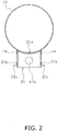
- FIG. 2 is a sectional view along line segment II-II of FIG. 1 .
- parts housed inside a casing 10 are omitted.
- the compressor 101 has a casing 10.
- the casing 10 is formed by a rigid member that is unlikely to be deformed or damaged by changes in pressure and temperature in the space inside and the space outside the casing 10.
- the material of the casing 10 is, for example, metal including carbon steel and iron such as cast iron.
- a compression mechanism Inside the casing 10 are housed a compression mechanism, a drive motor, and a crankshaft, for example.
- the compression mechanism is coupled to the drive motor via the crankshaft.
- the drive motor uses electrical power supplied from a power supply outside the casing 10 to rotate the crankshaft.
- the rotation of the crankshaft causes one of the pair of scroll members to revolve, thereby changing the volume of the space enclosed by the pair of scroll members, whereby the compression mechanism compresses the refrigerant.
- the casing 10 is configured from an open cylinder-shaped middle portion 11, a bowl-shaped top portion 12, and a bowl-shaped bottom portion 13.
- the top portion 12 is airtightly joined to the upper end portion of the middle portion 11.
- the bottom portion 13 is airtightly joined to the lower end portion of the middle portion 11.
- parts that become attached to the middle portion 11 will be generically called externally attached parts.
- the externally attached parts include not only parts that become attached to the outer surface of the middle portion 11 but also the top portion 12 and the bottom portion 13.
- the material of the externally attached parts is, for example, metal including carbon steel and iron such as cast iron.
- a terminal guard mounting seat 14, a discharge pipe 20, a terminal guard 31, and a sensor mounting seat 34 are attached as externally attached parts to the side surface of the middle portion 11.
- a suction pipe 19 and an injection pipe 35 are attached as externally attached parts to the side surface of the top portion 12.
- a hanger 33 is attached as an externally attached part to the upper surface of the top portion 12.
- a mounting foot 32 is attached as an externally attached part to the lower surface of the bottom portion 13.
- the terminal guard 31 is a member for protecting a terminal 41 connected to the drive motor inside the casing 10.
- the terminal 41 projects from the outer surface of the middle portion 11.
- the terminal guard 31 is attached to the terminal guard mounting seat 14, which is secured to the outer surface of the middle portion 11. The detailed configurations of the terminal guard 31 and the terminal guard mounting seat 14 will be described later.
- the mounting foot 32 is a member for securing the compressor 101 to an installation surface.
- the mounting foot 32 has, for example, bolt holes for securing it with bolts to the installation surface.
- the hanger 33 is a member for hanging the compressor 101.
- the hanger 33 has, for example, an annular portion for catching a hook or the like.
- the hanger 33 is used to hang the compressor 101 when, for example, assembling and transporting the compressor 101.
- the sensor mounting seat 34 is a member for attaching a temperature sensor or the like to the middle portion 11.
- the temperature sensor is used, for example, to measure the temperature of the outer surface of the middle portion 11 to monitor the temperature of the refrigerant inside the compressor 101.
- the injection pipe 35 is a member for injecting intermediate-pressure refrigerant into the compression mechanism to enhance the efficiency of the refrigeration cycle.
- a compressor assembly 111 of the present embodiment is a semi-manufactured product of the compressor 101 and corresponds to the compressor 101 in a state in which the terminal guard 31 has not been attached.
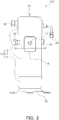
- FIG. 3 is a front view of the compressor assembly 111.
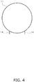
- FIG. 4 is a sectional view along line segment IV-IV of FIG. 3 . In FIG. 4 , parts housed inside the casing 10 are omitted.
- the terminal guard mounting seat 14 is attached to the outer surface of the middle portion 11.
- the terminal guard mounting seat 14 is a tubular member close to a quadrangular prism with curved corner portions. As shown in FIG. 3 , the terminal guard mounting seat 14 is attached to the outer surface of the middle portion 11 so as to surround the terminal 41.
- the terminal guard mounting seat 14 has a shape into which the terminal guard 31 becomes fitted. As shown in FIG. 2 , the terminal guard 31 can be fitted into the terminal guard mounting seat 14 in such a way that the outer peripheral surface of the terminal guard 31 contacts the inner peripheral surface of the terminal guard mounting seat 14. The terminal guard 31 that has been fitted into the terminal guard mounting seat 14 projects from the terminal guard mounting seat 14.
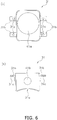
- FIG. 5(a) is an external view, seen from the front, of the terminal guard mounting seat 14 attached to the outer surface of the middle portion 11.
- FIG. 5(b) is an external view, seen from the side, of the terminal guard mounting seat 14 attached to the outer surface of the middle portion 11.
- the terminal guard mounting seat 14 is attached to the outer surface of the middle portion 11 by welding at four weld points 51.
- two weld points 51 are shown as circular regions surrounded by dotted lines.
- Two weld points 51 are also present on the opposite side of the side surface of the terminal guard mounting seat 14 shown in FIG. 5(b) .
- the number of the weld points 51 is appropriately set in accordance with, for example, the dimensions and the shape of the terminal guard mounting seat 14.
- the gap between the terminal guard mounting seat 14 and the middle portion 11 is filled with a caulking agent.
- the caulking agent prevents water and the like from getting inside the terminal guard mounting seat 14.
- the terminal guard mounting seat 14 may also be welded to the outer surface of the middle portion 11 along the entire periphery of the terminal guard mounting seat 14 rather than being welded to the outer surface of the middle portion 11 at the four weld points 51. In this case, the gap between the terminal guard mounting seat 14 and the middle portion 11 does not need to be filled with a caulking agent.
- FIG. 6(a) is a front view of the terminal guard 31.
- FIG. 6(b) is a bottom view of the terminal guard 31.
- FIG. 7 and FIG. 8 are drawings for describing the process of attaching the terminal guard 31 to the compressor assembly 111.
- the top portion 12 and the bottom portion 13 are already attached to the middle portion 11.
- the terminal guard mounting seat 14, the discharge pipe 20, and the sensor mounting seat 34 are attached to the outer surface of the middle portion 11.
- the terminal 41 projects from the outer surface of the middle portion 11.
- the hanger 33, the suction pipe 19, and the injection pipe 35 are attached to the outer surface of the top portion 12.
- the mounting foot 32 is attached to the outer surface of the bottom portion 13.
- the terminal guard 31 has a shape close to a quadrangular prism with curved corner portions.
- the terminal guard 31 is formed from a resin, a ceramic, or an aluminum alloy, for example, that has corrosion resistance. Because of this, the corrosion resistance of the terminal guard 31 can be improved in a case where the compressor 101 is used in an environment where high corrosion resistance is required, such as a marine environment.
- the terminal guard 31 has a curved portion 31a that contacts the outer surface of the middle portion 11 when the terminal guard 31 is attached to the terminal guard mounting seat 14. As shown in FIG. 6(b) , the curved portion 31a curves in conformity to the open cylinder shape of the middle portion 11.
- the terminal guard 31 has a terminal hole 41a, through which the terminal 41 passes, and a cable hole 41b, to which a later-described cable ground 31d is attached.
- the terminal hole 41a is formed in the face that has the curved portion 31a.
- the cable hole 41b is formed in the lower face of the terminal guard 31.
- cover securing members 31b are attached to the terminal guard 31.
- the cover securing members 31b are members that project outward from the end portion of the terminal guard 31 on the opposite side of the curved portion 31a.
- Each cover securing member 31b has one bolt fastening hole 31c.
- the bolt fastening holes 31c are holes for passing bolts for securing a terminal cover (not shown in the drawings) to the terminal guard 31.
- the terminal cover completely covers the open portion of the terminal guard 31.
- FIG. 9(a) is an external view, seen from the front, of the terminal guard 31 attached to the terminal guard mounting seat 14.
- FIG. 9(b) is an external view, seen from the side, of the terminal guard 31 attached to the terminal guard mounting seat 14.
- the method of attaching the terminal guard 31 to the terminal guard mounting seat 14 is arbitrary.
- the gap between the terminal guard 31 and the middle portion 11 and the gap between the terminal guard 31 and the terminal guard mounting seat 14 are filled with a caulking agent. It will be noted that in a case where these gaps are closed by welding, for example, along their entire peripheries, they do not need to be filled with a caulking agent.
- a cable ground 31d is airtightly attached to the cable hole 41b in the terminal guard 31.
- the cable ground 31d is a resin part through which a cable connected to the terminal 41 passes.
- the caulking agent and the cable ground 31d prevent water and the like from getting inside the terminal guard 31 to which the terminal cover is attached.
- the masked portions are portions where thermal spraying is prohibited in a subsequent thermal spraying process.
- the portions where thermal spraying is prohibited are, for example, outer surfaces that include portions that become coupled to external parts.
- the masked portions are indicated as hatched regions.
- the middle portion 11 the masked portions are the end portion of the discharge pipe 20, the end portion of the sensor mounting seat 34, and the terminal 41.
- the top portion 12 the masked portions are the end portion of the suction pipe 19 and the end portion of the injection pipe 35.
- the masked portion if present, is the outer surface on which a thermal spray coating has already been formed.
- thermal spraying is administered to the outer surfaces of the middle portion 11, the top portion 12, and the bottom portion 13.
- Thermal spraying is a surface treatment technique in which a thermal spray material heated to liquid droplets is sprayed onto the surface of a substrate that is a process target to thereby form a coating on the surface.
- the coating formed by the thermal spraying will be called a thermal spray coating.
- a thermal spray coating By administering the thermal spraying using a thermal spray material made of metal, a metal thermal spray coating is formed on the outer surfaces of the middle portion 11, the top portion 12, and the bottom portion 13.
- the thermal spray coating is not formed on the masked portions. In this way, masking is used to prevent the formation of the thermal spray coating.
- the thermal spraying has been administered to the outer surfaces of the middle portion 11, the top portion 12, and the bottom portion 13, the masking on the outer surfaces of the middle portion 11, the top portion 12, and the bottom portion 13 is removed.
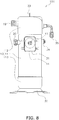
- FIG. 8 shows the compressor assembly 111 to which the terminal guard 31 has been attached.
- the portions where the thermal spray coating has not been formed because of masking are indicated as hatched regions.
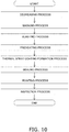
- FIG. 10 is a flowchart of the thermal spraying process.
- the thermal spraying process is configured mainly from a degreasing process, a masking process, a blasting process, a preheating process, a thermal spray coating formation process, a sealing process, a painting process, and an inspection process.
- a process surface the surface on which the thermal spray coating becomes formed.
- the degreasing process is a process that removes contaminants such as oil sticking to the process surface.
- the degreasing process is performed to prevent the process surface before it is thermal sprayed from rusting due to contaminants. Furthermore, the degreasing process is performed to remove anti-rust oil that has been applied beforehand to the process surface and contaminants sticking to the process surface.
- it is necessary to transfer the compressor assembly 111 after having attached the top portion 12 and the bottom portion 13 to the middle portion 11 to assemble the compressor assembly 111 sometimes it takes time until the blasting process starts. In this case, there is the concern that the process surface will rust due to contaminants during the transfer of the compressor assembly 111.
- the adhesive strength of the thermal spray coating drops, causing a drop in the corrosion resistance of the process surface. Furthermore, even in a case where anti-rust oil has been applied beforehand to the process surface for an anti-rust treatment, if the anti-rust oil remains on the process surface when the thermal spray coating is formed, the adhesive strength of the thermal spray coating drops, causing a drop in the corrosion resistance of the process surface. For that reason, it is necessary to completely remove contaminants from the process surface before the blasting process starts.
- the masking process is a process that protects masking regions that are portions where the thermal spray coating must not be formed.
- the masking regions correspond to the aforementioned "portions where thermal spraying is prohibited.”
- the masking regions are outer surfaces to which thermal spraying has already been administered and outer surfaces including portions that become coupled to external parts.
- the masking regions of the middle portion 11 are the end portion of the discharge pipe 20, the end portion of the sensor mounting seat 34, and the terminal 41, for example.
- the masking regions of the top portion 12 are the end portion of the suction pipe 19 and the end portion of the injection pipe 35, for example.
- the masking regions of the bottom portion 13 are the bolt holes in the mounting foot 32, for example.
- the masking regions are covered with masking jigs such as heat-resistant masking tape and heat-resistant masking caps.
- the heat-resistant masking tape is affixed to masking regions that are surfaces having substantially no recessed portions or raised portions.
- the heat-resistant masking caps are put over masking regions that project from surfaces, such as the end portion of the discharge pipe 20 and the end portion of the suction pipe 19.
- the blasting process is a process that roughens the process surface and a process that removes oxide scales sticking to the process surface.
- the target of the blasting process is the entire process surface where the thermal spray coating is to be formed.
- the blasting process is performed to improve the ability of the thermal spray coating to adhere to the process surface.
- the thermal spray coating mechanically adheres to the process surface because of the anchor effect. For that reason, if the surface roughness of the process surface is too low or if contaminants such as oxide scales are sticking to the process surface, there is the concern that the thermal spray coating will become more likely to separate from the process surface.
- a powder abrasive made of iron or aluminum oxide is blasted onto the process surface, whereby the process surface is roughened and oxide scales and the like sticking to the process surface are removed.
- the shape and the cleanliness of the process surface after the blasting process are important. For that reason, for the employed blasting process, grit blasting using an abrasive having a pointed shape is preferred over shot blasting using a spherical abrasive.
- Grit blasting compared to shot blasting, more easily forms a process surface that has a pointed shape and whose surface roughness is higher.
- contaminants such as oxide scales sticking to the process surface lower the ability of the thermal spray coating to adhere to the process surface and cause separation of the thermal spray coating.
- the cleanliness of the process surface after the blasting process be as high as possible.
- Grit blasting compared to shot blasting, more easily removes contaminants sticking to the process surface.
- grit blasting is employed.
- the material of the abrasive used in the blasting process be a material whose hardness is high, such as aluminum oxide. This is because the higher the hardness of the abrasive is, the higher the surface area and the cleanliness of the process surface after the blasting process become, and the ability of the thermal spray coating to adhere to the process surface tends to improve.
- the casing 10 is formed from various materials of different hardnesses, such as steel, stainless steel, casting, and brass. For that reason, it is preferred that the conditions of the blasting process be set in accordance with the materials of the casing 10 so that a shape, surface roughness, and cleanliness that are good for the entire outer surface of the casing 10 are obtained.
- the preheating process is a process that heats the process surface before the thermal spray coating is formed on the process surface.
- the preheating process is performed to improve the ability of the thermal spray coating to adhere to the process surface. If water and contaminants are sticking to the process surface when the thermal spray coating is formed, this causes a drop in the adhesive strength between the thermal spray coating and the process surface. For that reason, it is desired to preheat the process surface, before the thermal spray coating is formed, to remove water and contaminants sticking to the process surface.
- the preheating process be performed in such a way that the temperature of the process surface does not exceed 150 °.
- the thermal spray coating formation process is a process that uses thermal spraying to form a metal thermal spray coating on the process surface.
- the thermal spray material used in the thermal spray coating formation process is metal.
- the thermal spray material be aluminum, magnesium, zinc, and an alloy comprising any of these.
- an appropriate method is selected from flame spraying, arc spraying, and plasma spraying, for example, in accordance with the thermal spray material.
- an appropriate value is set in accordance with, for example, the corrosion resistance required of the process surface, the range of temperature variation in the process surface that occurs when the compressor 101 operates, and the shape of the compressor 101, so that cracks in the thermal spray coating due to internal stress and thermal expansion, for example, do not occur. It is preferred that chamfering be administered beforehand to edge portions of the outer surface of the casing 10 because the thickness of the thermal spray coating tends to become thin at the edge portions.
- the time between the blasting process and the thermal spray coating formation process be within 4 hours. This is because there is the concern that the longer the time is between the blasting process and the thermal spray coating formation process, the more likely it will be for the adhesive strength of the thermal spray coating to the process surface to drop because of the activity of the process surface dropping and water and the like sticking to the process surface.
- the sealing process is a process that fills holes in the thermal spray coating that has been formed on the process surface. Holes in the thermal spray coating cause a drop in the corrosion resistance of the process surface because the process surface is exposed to outside air. For that reason, the sealing process is performed to inhibit a drop in the corrosion resistance of the process surface.
- a sealing agent is applied to the process surface on which the thermal spray coating has been formed.
- the sealing process should be performed the day the thermal spray coating formation process was performed. This is because there is the concern that the longer the time is between the thermal spray coating formation process and the sealing process, the more likely it will be for water and contaminants to stick to the process surface and make it harder for the sealing agent to penetrate into the thermal spray coating, so that the corrosion resistance required of the process surface is not obtained.
- sealing agents such as silicon resin, acrylic resin, epoxy resin, urethane resin, and fluorocarbon resin.
- an appropriate sealing agent should be selected to match the purpose and the use environment of the compressor 101.
- the same method as that used for ordinary painting of the outer surface of the casing 10, such as painting with a brush, spraying with a spray, and immersion in a sealing agent bath, can be used.
- an appropriate value is selected in accordance with, for example, the corrosion resistance required of the process surface, the range of temperature variation in the process surface that occurs when the compressor 101 operates, and the shape of the compressor 101, so that cracks in the thermal spray coating due to internal stress and thermal expansion, for example, do not occur.
- the painting process is a process where a paint such as oil paint is applied to the process surface on which the thermal spray coating has been formed, to thereby improve the external appearance. It is preferred that the paint used in the painting process be a paint with a good ability to adhere to the thermal spray coating.
- the inspection process is a process of inspecting the process surface on which the thermal spray coating has been formed. Specifically, in the inspection process, the adhesive strength of the thermal spray coating to the process surface and the thickness of the thermal spray coating are measured, and it is determined whether or not the measurement values meet predetermined requirements.
- the measurement be performed on a part of the outer surface of the casing 10 that has substantially no recessed portions or raised portions. For that reason, it is preferred that a surface for measuring the adhesive strength and the thickness of the thermal spray coating be formed beforehand on the casing 10.
- the adhesive strength and the thickness of the thermal spray coating that has been formed on the surface of a masking jig that was used in the masking process may also be measured.
- the material of the masking jig be identical or similar to the material of the casing 10.
- the compressor assembly 111 pertaining to the present embodiment is a semi-manufactured product of the compressor 101 and corresponds to the compressor 101 in a state in which the terminal guard 31 for protecting the terminal 41 connected to the power supply has not been attached.
- the terminal guard mounting seat 14 for attaching the terminal guard 31 is attached to the outer surface of the middle portion 11 around the terminal 41.
- a good thermal spray coating can also be formed on the outer surface around the terminal guard mounting seat 14. This is because after the terminal guard 31 has been attached to the middle portion 11 it is difficult to spray the thermal spray material from an appropriate direction onto, and therefore difficult to form a good thermal spray coating on, the outer surface that is in the shadow of the terminal guard 31.
- the compressor assembly 111 can manufacture the compressor 101 having a good thermal spray coating formed also around the terminal guard 31. Furthermore, in the compressor assembly 111, terminal guards 31 of various shapes can be attached to the terminal guard mounting seat 14. For that reason, the compressor assembly 111 can manufacture the compressor 101 in which it is easy to replace the terminal guard 31.
- a metal coating for improving corrosion resistance is formed by thermal spraying on the outer surface of the middle portion 11 of the compressor 101 in a state in which the terminal guard 31 for protecting the terminal 41 connected to the power supply has not been attached.
- the metal spraying is administered, just the terminal guard mounting seat 14 for attaching the terminal guard 31 is attached to the outer surface of the middle portion 11 around the terminal 41. For that reason, when administering the metal spraying to the outer surface of the middle portion 11, a good thermal spray coating can also be formed on the outer surface around the terminal guard mounting seat 14.
- the compressor 101 by using stainless steel to make the terminal guard 31, the compressor 101 whose corrosion resistance is high even without administering the metal spraying can be manufactured. For that reason, in a case where the compressor 101 is not used in an environment where high corrosion resistance is required, such as a marine environment, the metal spraying of the terminal guard 31 can be omitted from the manufacturing process of the compressor 101 by using stainless steel to make the terminal guard 31. Consequently, in this case, the cost of the manufacturing process of the compressor 101 can be reduced.
- the portions where thermal spraying is prohibited which are parts of the outer surfaces of the middle portion 11, the top portion 12, and the bottom portion 13, are masked.
- the portions where thermal spraying is prohibited are, for example, outer surfaces to which thermal spraying has already been administered and outer surfaces including portions that become joined to external parts such as refrigerant pipes. Consequently, in the compressor 101, by masking the portions where thermal spraying is prohibited, unnecessary use of thermal spray material resulting from thermal spraying outer surfaces to which thermal spraying has already been administered and poor joining to external parts are inhibited.
- terminal guards 31 of various shapes can be attached to the terminal guard mounting seat 14. For that reason, in this method of manufacturing the compressor 101, the compressor 101 in which it is easy to replace the terminal guard 31 can be manufactured.
- the advantages of forming a metal thermal spray coating as the spray coating formed on the outer surfaces of the middle portion 11 and the externally attached parts are as follows.
- the thermal spray coating that has been formed using as the thermal spray material a metal (e.g., aluminum) whose ionization tendency is greater than that of iron which is the main component of the material of the middle portion 11 and the externally attached parts is corroded before the middle portion 11 and the externally attached parts that are the substrate. For that reason, as long as the thermal spray coating does not separate from the substrate, the anti-corrosion effect whereby corrosion and damage of the substrate due to rust lasts.
- a metal e.g., aluminum
- the difference in the coefficients of linear expansion between a metal thermal spray coating and iron which is the main component of the material of the middle portion 11 and the externally attached parts is small. For that reason, for example, even if during the operation of the compressor 101 a wide temperature variation such as -40 °C to 140 °C arises in the outer surface of the middle portion 11, cracks in the thermal spray coating caused by the difference in the coefficients of linear expansion are less likely to occur.
- a metal thermal spray coating allows virtually no water to pass through compared to a coating of paint whose main component is resin. For that reason, separation of the thermal spray coating caused by water passing through the thermal spray coating and accumulating in the boundary between the thermal spray coating and the outer surfaces of the middle portion 11 and the external attached parts that are the substrate is less likely to occur.
- a metal thermal spray coating has high ductility compared to a coating of paint whose main component is resin. For that reason, blemishes and dimples in the thermal spray coating due to physical stress such as flying rocks are less likely to occur.
- a metal thermal spray coating has about 5 times the adhesive strength to the outer surfaces of the middle portion 11 and the externally attached parts that are the substrate compared to a coating of paint whose main component is resin. For that reason, separation of the thermal spray coating from the substrate due to deterioration over time is less likely to occur.
- a metal thermal spray coating has high thermal conductivity compared to a coating of paint whose main component is resin. For that reason, when the compressor 101 has stopped, the heat of high-temperature portions of the outer surface of the casing 10 more easily travels to low-temperature portions, and frost and ice sticking to the outer surface of the casing 10 quickly melt.
- the metal spraying of the terminal guard 31 can be omitted from the manufacturing process of the compressor 101.
- the metal spraying may also be administered to the outer surface of the terminal guard 31.
- the metal spraying is administered to the terminal guard 31 before attaching the terminal guard 31 to the terminal guard mounting seat 14.
- the terminal guard 31 is metal sprayed before it is attached to the terminal guard mounting seat 14
- a good metal coating can be formed by spraying the thermal spray material from appropriate directions onto the entire outer surface of the terminal guard 31. Consequently, in this method of manufacturing the compressor 101, a good thermal spray coating can be formed on the terminal guard 31.
- the corrosion resistance of the terminal guard 31 can be improved in a case where the compressor 101 is used in an environment where high corrosion resistance is required, such as a marine environment.
- the degreasing process for removing contaminants sticking to the process surface before it is thermal sprayed is performed.
- a simple anti-rust treatment may also be performed by applying a paint to the process surface before it is thermal sprayed. In this case, it is preferred to select a paint that can be easily removed from the process surface before blasting the process surface.
- the masking process for protecting the masking regions that are portions of the process surface-before it is thermal sprayed-on which a thermal spray coating must not be formed is performed.
- the masking process may also be performed for the purpose of inscribing predetermined characters and marks, for example, on the process surface in addition to the purpose of protecting the masking regions.
- a masking process where the masking regions are protected by masking jigs in which characters and marks, for example, have been cut out and where thereafter thermal spraying is administered to the process surface and the masking jigs are removed may also be performed. Because of this, characters and marks, for example, are inscribed on the process surface depending on whether or not there is a thermal spray coating.
- the blasting process that uses grit blasting to roughen the process surface is performed.
- a process that roughens the process surface by applying a surface roughening agent to the process surface may also be performed instead of a surface roughening process using grit blasting.
- the thermal spray coating formation process in which aluminum, magnesium, zinc, and an alloy comprising any of these is used as the thermal spray material, is performed.
- a ceramic or a mixture of a metal and a ceramic may also be used as the thermal spray material.
- the thermal spray coating formed by such a ceramic thermal spray material has a good ability to block the process surface from the external environment and improves the corrosion resistance of the process surface.
- the thermal spray coating formation process that forms the thermal spray coating on the process surface is performed.
- the thermal spray coating does not need to be a single layer, and a thermal spray coating comprising plural layers may also be formed on the process surface.
- a thermal spray coating using aluminum, magnesium, zinc, and an alloy comprising any of these as the thermal spray material may be formed on the process surface, and on top of that thermal spray coating another thermal spray coating using a ceramic or a mixture of a metal and a ceramic as the thermal spray material may be formed.
- a thermal spray coating comprising plural layers has a better ability to block the process surface from the external environment and improves the corrosion resistance of the process surface more than a single-layer thermal spray coating.
- the sealing process that fills holes in the thermal spray coating that has been formed on the process surface is performed.
- a resin sealing agent is applied to the process surface on which the thermal spray coating has been formed.
- a sealing agent containing metal flakes may also be used. In this case, the water transmission rate of the thermal spray coating is reduced by what is called the labyrinth effect, so a drop in the corrosion resistance of the process surface is effectively inhibited.
- the terminal guard mounting seat 14 is a tubular member close to a quadrangular prism with curved corner portions, and as shown in FIG. 9(b) , the terminal guard 31 is attached by welding to the terminal guard mounting seat 14.
- the terminal guard mounting seat 14 may also be a member with a shape other than a tubular shape, and the terminal guard 31 may also be attached to the terminal guard mounting seat 14 by a method other than welding.
- FIG. 11 is an external view, seen from the front, of terminal guard mounting seats 114 attached to the outer surface of the middle portion 11 in the present example modification.
- FIG. 12 is a sectional view of the terminal guard mounting seats 114 along line segment XII-XII of FIG. 11 .
- FIG. 13 is the same sectional view as FIG. 12 and is a sectional view of the terminal guard mounting seats 114 to which a terminal guard 131 has been attached.
- terminal guard mounting seats 114 are attached by welding, for example, to the outer surface of the middle portion 11.
- the terminal guard mounting seats 114 are columnar members having first end portions 115a and second end portions 115b.
- the first end portions 115a are end portions on the side that becomes attached to the outer surface of the middle portion 11.
- the second end portions 115b are end portions on the opposite side of the first end portions 115a and are end portions on the side to which the terminal guard 131 becomes attached.
- the number of the terminal guard mounting seats 114 is appropriately set in accordance with, for example, the dimensions of the terminal guard 131.
- the terminal guard mounting seats 114 have screw holes 114a.
- the screw holes 114a are formed in end faces on the second end portion 115b sides of the terminal guard mounting seats 114.
- the terminal guard 131 has a curved portion 131a, four cover securing members 131b, and four mounting seat securing members 131d.
- the cover securing members 131b correspond to the four cover securing members 31b of the embodiment and are members that project outward from the end portion of the terminal guard 131 on the opposite side of the curved portion 131a.
- Each cover securing member 131b has one bolt fastening hole 131c.
- the bolt fastening holes 131c are holes for passing bolts for securing a terminal cover (not shown in the drawings) to the terminal guard 131.
- the mounting seat securing members 131d are members that project outward from the end portion of the terminal guard 131 on the curved portion 131a side.
- the number of the mounting seat securing members 131d is the same as the number of the terminal guard mounting seats 114.
- Each mounting seat securing member 131d has one screw through hole 131e.
- the screw through holes 131e are, together with the screw holes 114a in the terminal guard mounting seats 114, holes for passing screws 114b for securing the terminal guard 131 to the terminal guard mounting seats 114. As shown in FIG. 13 , the screws 114b pass through the screw through holes 131e in the terminal guard 131 and are fitted into the screw holes 114a in the terminal guard mounting seats 114.
- the terminal guard 131 is secured to the terminal guard mounting seats 114 by the screws 114b, so it is easy to attach, detach, and replace the terminal guard 131.
- the four terminal guard mounting seats 114 may also be coupled to each other and integrated as a member that is attached to the outer surface. In this case, the member corresponding to the four terminal guard mounting seats 114 can be easily attached to the outer surface of the middle portion 11.
- the terminal guard mounting seat 14 is a tubular member close to a quadrangular prism with curved corner portions, and as shown in FIG. 9(b) , the terminal guard 31 is attached by welding to the terminal guard mounting seat 14.
- the terminal guard mounting seat 14 may also be a member with a shape other than a tubular shape, and the terminal guard 31 may also be attached to the terminal guard mounting seat 14 by a method other than welding.
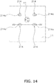
- FIG. 14 is an external view, seen from the front, of terminal guard mounting seats 214 attached to the outer surface of the middle portion 11 in the present example modification.
- FIG. 15 is a sectional view of the terminal guard mounting seats 214 along line segment XV-XV of FIG. 14 .
- FIG. 16 is the same sectional view as FIG. 15 and is a sectional view of the terminal guard mounting seats 214 to which a terminal guard 231 has been attached.
- the terminal guard mounting seats 214 are columnar members having first end portions 215a and second end portions 215b.
- the first end portions 215a are end portions on the side that becomes attached to the outer surface of the middle portion 11.
- the second end portions 215b are end portions on the opposite side of the first end portions 215a and are end portions on the side to which the terminal guard 231 becomes attached.
- the number of the terminal guard mounting seats 214 is appropriately set in accordance with, for example, the dimensions of the terminal guard 231.
- the terminal guard mounting seats 214 have ridges 214a.
- the ridges 214a are projections formed on end faces on the second end portion 215b sides of the terminal guard mounting seats 214.
- the terminal guard 231 has a curved portion 231a, four cover securing members 231b, and four mounting seat securing members 231d.
- the cover securing members 231b correspond to the four cover securing members 31b of the embodiment and are members that project outward from the end portion of the terminal guard 231 on the opposite side of the curved portion 231a.
- Each cover securing member 231b has one bolt fastening hole 231c.
- the bolt fastening holes 231c are holes for passing bolts for securing a terminal cover (not shown in the drawings) to the terminal guard 231.
- the mounting seat securing members 231d are members that project outward from the end portion of the terminal guard 231 on the curved portion 231a side.
- the number of the mounting seat securing members 231d is the same as the number of the terminal guard mounting seats 214.
- Each mounting seat securing member 231d has one ridge through hole 231e.
- the ridge through holes 231e are holes for passing the ridges 214a of the terminal guard mounting seats 214 to secure the terminal guard 231 to the terminal guard mounting seats 214. As shown in FIG. 16 , the ridges 214a pass through the ridge through holes 231e in the terminal guard 231 and are fastened by nuts 214b.
- the terminal guard 231 is secured to the terminal guard mounting seats 214 by the nuts 214b, so it is easy to attach, detach, and replace the terminal guard 231.
- the four terminal guard mounting seats 214 may also be coupled to each other and integrated as a member that is attached to the outer surface.
- the member corresponding to the four terminal guard mounting seats 214 can be easily attached to the outer surface of the middle portion 11.
- the terminal guard mounting seat 14 is a tubular member close to a quadrangular prism with curved corner portions, and as shown in FIG. 9(b) , the terminal guard 31 is attached by welding to the terminal guard mounting seat 14.
- the terminal guard mounting seat 14 may also be a member with a shape other than a tubular shape.
- FIG. 17 is an external view, seen from the front, of a terminal guard mounting seat 314 attached to the outer surface of the middle portion 11 in the present example modification.
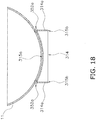
- FIG. 18 is a sectional view of the terminal guard mounting seat 314 along line segment XVIII-XVIII of FIG. 17 .
- FIG. 19 is the same sectional view as FIG. 18 and is a sectional view of the terminal guard mounting seat 314 to which a terminal guard 331 has been attached.
- the terminal guard mounting seat 314 is a bowl-shaped member.
- the body of the terminal guard mounting seat 314 will be called a bowl-shaped portion 315.
- the bowl-shaped portion 315 has a bottom portion 315a and an end portion 315b.
- the bottom portion 315a has a face attached to the outer surface of the middle portion 11 and curves along the shape of the outer surface of the middle portion 11.
- the bottom portion 315a has a terminal hole 315c through which the terminal 41 passes.
- the end portion 315b is an end portion on the opposite side of the bottom portion 315a and is an end portion on the side to which the terminal guard 331 becomes attached.
- the terminal guard mounting seat 314 is attached to the outer surface of the middle portion 11 by welding at weld points 352a shown in FIG. 18 .
- the weld points 352a are formed along the entire periphery of the bottom portion 315a of the terminal guard mounting seat 314.
- the gap between the terminal guard mounting seat 314 and the outer surface of the middle portion 11 is filled with a caulking agent.
- the terminal guard mounting seat 314 has four first bolt through holes 314a.
- the first bolt through holes 314a are formed in the end portion 315b of the terminal guard mounting seat 314.
- the number of the first bolt through holes 314a is appropriately set in accordance with, for example, the dimension of the terminal guard mounting seat 314.
- the terminal guard 331 has a tubular body 331a and four cover securing members 331b.
- the tubular body 331a is a portion into which the terminal guard mounting seat 314 becomes fitted.
- the inner peripheral surface of the tubular body 331a contacts the outer peripheral surface of the end portion 315b of the terminal guard mounting seat 314.
- the cover securing members 331b correspond to the four cover securing members 31b of the embodiment and are members that project outward from the end portion of the tubular body 331a on the opposite side of the terminal guard mounting seat 314.
- Each cover securing member 331b has one bolt fastening hole 331c.
- the bolt fastening holes 331c are holes for passing bolts for securing a terminal cover (not shown in the drawings) to the terminal guard 331.
- the tubular body 331a has four second bolt through holes 331e.
- the second bolt through holes 331e are holes for passing bolts 314b for securing the terminal guard 331 to the terminal guard mounting seat 314. As shown in FIG. 19 , the bolts 314b pass through the first bolt through holes 314a in the terminal guard mounting seat 314 and the second bolt through holes 331e in the terminal guard 331 and fasten the terminal guard mounting seat 314 and the terminal guard 331 to each other.
- the terminal guard mounting seat 314 is attached to the outer surface of the middle portion 11 by welding along the entire periphery of the bottom portion 315a, so the terminal guard mounting seat 314 can be strongly secured to the outer surface of the middle portion 11. Furthermore, the terminal guard 331 is secured by the bolts 314b to the terminal guard mounting seat 314, so it is easy to attach, detach, and replace the terminal guard 331.
- the terminal guard 331 may also be secured to the terminal guard mounting seat 314 by welding.
- FIG. 20 is the same sectional view as FIG. 19 and shows a configuration where the terminal guard 331 is secured to the terminal guard mounting seat 314 by welding.
- the terminal guard mounting seat 314 does not have the first bolt through holes 314a, and the terminal guard 331 does not have the second bolt through holes 331e.
- the terminal guard 331 is secured to the terminal guard mounting seat 314 by welding at weld points 352b shown in FIG. 20 .
- the weld points 352b are formed along the entire periphery of the outer peripheral surface of the terminal guard mounting seat 314. Because of this, the terminal guard 331 can be strongly secured to the terminal guard mounting seat 314.
- the terminal guard mounting seat 14 is a tubular member close to a quadrangular prism with curved corner portions, and as shown in FIG. 9(b) , the terminal guard 31 is attached by welding to the terminal guard mounting seat 14.
- the terminal guard mounting seat 14 may also be a member with a shape other than a tubular shape.
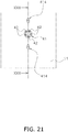
- FIG. 21 is an external view, seen from the front, of terminal guard mounting seats 414 attached to the outer surface of the middle portion 11 in the present example modification.
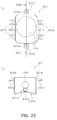
- FIG. 22(a) is a front view of a terminal guard 431 that becomes attached to the terminal guard mounting seats 414.
- FIG. 22(b) is a bottom view of the terminal guard 431.
- FIG. 23 is a sectional view of the terminal guard mounting seats 414 to which the terminal guard 431 has been attached.
- FIG. 23 is a sectional view along line segment XXIII-XXIII of FIG. 21 and FIG. 22 .
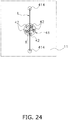
- FIG. 24 is a drawing for describing positions of the terminal guard mounting seats 414.
- two terminal guard mounting seats 414 are attached by welding, for example, to the outer surface of the middle portion 11.
- the two terminal guard mounting seats 414 are disposed in positions that sandwich the terminal 41.
- the terminal guard mounting seats 414 are columnar members having first end portions 415a and second end portions 415b.
- the terminal guard mounting seats 414 are, for example, studs in the shape of closed cylinders.
- the first end portions 415a are end portions on the side that becomes attached to the outer surface of the middle portion 11.
- the second end portions 415b are end portions on the opposite side of the first end portions 415a and are end portions on the side to which the terminal guard 431 becomes attached.
- the terminal guard 431 has a curved portion 431a, four cover securing members 431b, and two mounting seat securing members 431d.
- the cover securing members 431b correspond to the four cover securing members 31b of the embodiment and are members that project outward from the end portion of the terminal guard 431 on the opposite side of the curved portion 431a.
- Each cover securing member 431b has one bolt fastening hole 431c.
- the bolt fastening holes 431c are holes for passing bolts for securing a terminal cover (not shown in the drawings) to the terminal guard 431.
- the mounting seat securing members 431d are members that project outward from the end portion of the terminal guard 431 on the curved portion 431a side.
- the number of the mounting seat securing members 431d is the same as the number of the terminal guard mounting seats 414.
- Each mounting seat securing member 431d has one through hole 431e.
- the through holes 431e are holes through which the terminal guard mounting seats 414 pass. In order to attach the terminal guard 431 to the terminal guard mounting seats 414, as shown in FIG. 23 , the terminal guard mounting seats 414 secured to the outer surface of the middle portion 11 are passed through the through holes 431e in the terminal guard 431 from the side of the second end portions 415b.
- the neighborhoods of the through holes 431e are welded to secure the terminal guard 431 to the terminal guard mounting seats 414.
- the process of attaching the terminal guard 431 is easy and the terminal guard 431 can be strongly secured to the casing 10.
- the terminal guard 431 may also be secured to the terminal guard mounting seats 414 using securing members such as nuts.
- the terminal guard mounting seats 414 may be passed through the through holes 431e in the terminal guard 431 and then nuts (securing members) may be attached from the side of the second end portions 415b to the terminal guard mounting seats 414 to thereby secure the terminal guard 431.
- the two terminal guard mounting seats 414 may also be coupled to each other and integrated as a member that is attached to the outer surface of the middle portion 11.
- the member corresponding to the two terminal guard mounting seats 414 can be easily attached to the outer surface of the middle portion 11.
- the two terminal guard mounting seats 414 are disposed in positions that sandwich the terminal 41.
- the terminal 41 has plural terminal pins 42 to which a cable, for example, becomes attached.
- the terminal 41 which has five terminal pins 42, and the two terminal guard attachment seats 414 are shown.
- a terminal region R is a triangular region formed by interconnecting the centers of three terminal pins 42 out of the five terminal pins 42.
- the two terminal guard mounting seats 414 are disposed in "positions that sandwich the terminal 41".
- the centers of the terminal pins 42 are the centers of the regions occupied by the terminal pins 42 in a case where the terminal pins 42 are seen from a direction perpendicular to the outer surface of the middle portion 11.
- the centers of the terminal guard mounting seats 414 are the centers of the regions occupied by the terminal guard mounting seats 414 in a case where the terminal guard mounting seats 414 are seen from a direction perpendicular to the outer surface of the middle portion 11.
- the number of the terminal pins 42 and the number of the terminal guard mounting seats 414 are arbitrary. In a case where the number of the terminal guard mounting seats 414 is three or more, it suffices for an arbitrary two of the terminal guard mounting seats 414 to be disposed in positions that sandwich the terminal 41.
- the terminal guard mounting seat 14 is attached to the outer surface of the middle portion 11.
- the terminal guard mounting seat 14 may also be attached to the outer surface of the casing 10 somewhere other than the outer surface of the middle portion 11.
- the terminal guard mounting seat 14 may also be attached to the outer surface of the top portion 12.
- the compressor assembly 111 has a body and a terminal guard attachment seat 14 attached to an outer surface of the body
- the body means the casing 10 comprising the middle portion 11, the top portion 12, and the bottom portion 13.
- the terminal guard mounting seat 14 may be attached to the outer surface of any of the middle portion 11, the top portion 12, and the bottom portion 13.
- FIG. 25 is an example of a front view of the compressor 101 in the present example modification. Substantially the only difference between FIG. 25 and FIG. 1 pertaining to the embodiment is the attachment position of the terminal guard mounting seat.
- the terminal guard mounting seats 414 of example modification K are attached to the bowl-shaped top portion 12 of the casing 10. Specifically, the terminal guard mounting seats 414 are secured by welding to the uppermost face of the top portion 12.
- the terminal guard 431 of example modification K is secured to the terminal guard mounting seats 414.
- any of the terminal guard mounting seat 14 of the embodiment and the terminal guard mounting seats 114, 214, and 314 of example modifications H, I, and J may also be attached to the top portion 12.
- the compressor pertaining to the invention has a good thermal spray coating formed around the terminal guard.
Landscapes
- Engineering & Computer Science (AREA)
- Mechanical Engineering (AREA)
- Chemical & Material Sciences (AREA)
- General Engineering & Computer Science (AREA)
- Physics & Mathematics (AREA)
- Plasma & Fusion (AREA)
- Chemical Kinetics & Catalysis (AREA)
- Materials Engineering (AREA)
- Metallurgy (AREA)
- Organic Chemistry (AREA)
- Compressor (AREA)
- Applications Or Details Of Rotary Compressors (AREA)
Abstract
Description
- The present invention relates to a compressor assembly that becomes a compressor as a result of a terminal guard being attached, and a compressor that is manufactured from the compressor assembly, and a method of manufacturing the compressor.
- A compressor used in a refrigerating system has a casing configured from plural members formed of metal such as carbon steel and cast iron. A surface treatment for inhibiting damage caused by rust, for example, and improving corrosion resistance is administered to the outer surface of the casing of the compressor. The corrosion resistance of the casing is an important characteristic for extending the product life of the compressor. In particular, the casing of a compressor used in a marine environment is required to have high corrosion resistance because it is easily exposed to spray and mist including seawater components and it is subject to sudden temperature changes. Compressors used in a marine environment include, for example, compressors for refrigerating systems used in marine containers that are loaded onto a container ship and transported across the ocean.
- In compressors used in home air conditioners, for example, there are cases where a coating resulting from the painting of an oil paint or resin, for example, is formed on the outer surface of the casing to improve corrosion resistance. However, a coating formed by painting is vulnerable to changes in temperature, the infiltration of water to the interface, and physical shocks. For that reason, depending on the use environment, sometimes the coating cracks and sometimes the coating separates from the surface of the substrate of the casing. In the case of a compressor used in a marine environment, if the substrate of the casing is exposed to the outside air due to cracking and separation of the coating, it becomes extremely easy for corrosion of the casing to progress. Additionally, if the compressor sustains damage due to corrosion of the casing, there is the concern that a large economic loss will occur because it is usually difficult to repair a compressor in a marine environment. For that reason, the casing of a compressor used in a marine environment needs to have a particularly high corrosion resistance.
- Conventionally, as disclosed in patent document 1 (
JP-A No. 2002-303272 JP-A No. 2011-509342 - The casing of a compressor has various projecting portions and has a complex shape. The projecting portions are members that project from the outer surface of the casing, such as refrigerant pipes, a terminal guard, and a mounting foot. On the outer surfaces of the projecting portions and the outer surface of the casing around the projecting portions are formed difficult-to-spray regions where it is difficult to carry out the process of spraying the thermal spray material because they are in shadows. The difficult-to-spray regions tend to have a small thermal spray coating thickness and a low corrosion resistance compared to other regions of the outer surface of the casing. In order to also form on the difficult-to-spray regions a thermal spray coating of about the same thickness as the other regions of the outer surface of the casing, it is necessary to spray the thermal spray material at a right angle to the difficult-to-spray regions. However, because the casing having the projecting portions has a complex shape, it is difficult to form a uniform thermal spray coating on the entire outer surfaces of the projecting portions and the casing. In particular, a terminal guard, which is a projecting portion that is erectly provided around a terminal that projects from the outer surface of the casing, is attached to the outer surface of the casing, so it is difficult to spray the thermal spray material from appropriate directions onto the outer surface of the casing around the attachment position of the terminal guard.
- It is an object of the present invention to provide a compressor having a good thermal spray coating formed around the terminal guard, and a compressor assembly that is a semi-manufactured product of the compressor, and a method of manufacturing the compressor.
- A compressor assembly pertaining to a first aspect of the invention becomes a compressor as a result of a terminal guard being attached. The compressor assembly has a body and a terminal guard mounting seat. The terminal guard mounting seat is attached to an outer surface of the body, and the terminal guard becomes attached to the terminal guard mounting seat.
- This compressor assembly is a semi-manufactured product of the compressor and is the compressor in a state in which the terminal guard for protecting a terminal connected to a power supply has not been attached. Just the terminal guard mounting seat for attaching the terminal guard is attached to the outer surface of the body around the terminal. For that reason, when administering metal spraying to the outer surface of the body, a good thermal spray coating can also be formed on the outer surface around the terminal guard mounting seat. This is because after the terminal guard has been attached to the body it is difficult to form a good thermal spray coating on the outer surface that is in the shadow of the terminal guard. Consequently, this compressor assembly can manufacture the compressor having a good thermal spray coating formed also around the terminal guard. Furthermore, in this compressor assembly, terminal guards of various shapes can be attached to the terminal guard mounting seat. For that reason, this compressor assembly can manufacture the compressor in which it is easy to replace the terminal guard.
- A compressor assembly pertaining to a second aspect of the invention is the compressor assembly pertaining to the first aspect, wherein metal spraying is administered to at least part of the outer surface of the body.
- In this compressor assembly, metal spraying is administered to the outer surface of the body to which the terminal guard mounting seat has been attached. The terminal guard has not been attached to the terminal guard mounting seat. For that reason, in this compressor assembly, when administering the metal spraying to the outer surface of the body, a good thermal spray coating can also be formed on the outer surface around the terminal guard mounting seat.
- A compressor pertaining to a third aspect of the invention has the compressor assembly pertaining to the first aspect or the second aspect and a terminal guard attached to the compressor assembly.
- In this compressor, a good thermal spray coating is also formed on the portion that projects from the outer surface of the casing. Furthermore, in this compressor, it is easy to replace the terminal guard.
- A compressor pertaining to a fourth aspect of the invention is the compressor pertaining to the third aspect, wherein the terminal guard is made of stainless steel.
- In this compressor, the terminal guard is made of stainless steel, so corrosion resistance is high even without administering the metal spraying. For that reason, depending on the use environment of the compressor, the metal spraying of the terminal guard can be omitted from the manufacturing process of the compressor. Consequently, with this compressor, the cost of the manufacturing process can be reduced.
- A compressor pertaining to a fifth aspect of the invention is the compressor pertaining to the third aspect or the fourth aspect, wherein the terminal guard is erectly provided around a terminal that projects from the outer surface.
- In this compressor, a good thermal spray coating is formed around the terminal guard.
- A compressor pertaining to a sixth aspect of the invention is the compressor pertaining to the fifth aspect, wherein the terminal guard is attached to the terminal guard mounting seat by securing members or welding.
- In this compressor, in a case where the terminal guard is attached to the terminal guard mounting seat by securing members such as bolts and nuts, it is easy to replace the terminal guard. Furthermore, in this compressor, in a case where the terminal guard is attached to the terminal guard mounting seat by welding, the terminal guard can be strongly secured to the terminal guard mounting seat.
- A compressor pertaining to a seventh aspect of the invention is the compressor pertaining to the fifth aspect or the sixth aspect, wherein the terminal guard mounting seat has a tubular portion. One end portion of the tubular portion is attached to the outer surface of the body. The other end portion of the tubular portion has the terminal guard attached to it.
- In this compressor, the terminal guard mounting seat has the tubular portion, so the terminal guard mounting seat can be easily secured to the outer surface of the body.
- A compressor pertaining to an eighth aspect of the invention is the compressor pertaining to the fifth aspect or the sixth aspect, wherein the terminal guard mounting seat has a columnar portion. One end portion of the columnar portion is attached to the outer surface of the body. The other end portion of the columnar portion has the terminal guard attached to it.
- In this compressor, the terminal guard mounting seat has the columnar portion, so the terminal guard mounting seat can be easily secured to the outer surface of the body.
- A compressor pertaining to a ninth aspect of the invention is the compressor pertaining to the eighth aspect, wherein the terminal guard mounting seat has at least two of the columnar portions disposed in positions that sandwich the terminal.
- In this compressor, the terminal guard can be stably secured.
- A compressor pertaining to a tenth aspect of the invention is the compressor pertaining to the fifth aspect or the sixth aspect, wherein the terminal guard mounting seat has a bowl-shaped portion. A bottom portion of the bowl-shaped portion is attached to the outer surface of the body. An end portion on the opposite side of the bottom portion of the bowl-shaped portion has the terminal guard attached to it.
- In this compressor, the bottom portion of the bowl-shaped portion of the terminal guard mounting seat is attached to the outer surface of the body, so the terminal guard mounting seat is strongly secured to the outer surface of the body.
- A compressor manufacturing method pertaining to an eleventh aspect of the invention is a method of manufacturing the compressor of any one of the third aspect to the tenth aspect, which has a body and a terminal guard erectly provided around a terminal that projects from an outer surface of the body, the method having a terminal guard mounting seat attachment step, a body spraying step, and a terminal guard attachment step. The terminal guard mounting seat attachment step is a step of attaching to the outer surface of the body a terminal guard mounting seat to which the terminal guard becomes attached. The body spraying step is a step of administering metal spraying to at least part of the outer surface of the body after the terminal guard mounting seat attachment step. The terminal guard attachment step is a step of attaching the terminal guard to the terminal guard mounting seat after the body spraying step.
- In this compressor manufacturing method, a metal coating for improving corrosion resistance is formed by thermal spraying on the outer surface of the body of the compressor in a state in which the terminal guard for protecting a terminal connected to a power supply has not been attached. When the metal spraying is administered, just the terminal guard mounting seat for attaching the terminal guard is attached to the outer surface of the body around the terminal. For that reason, when administering the metal spraying to the outer surface of the body, a good thermal spray coating can also be formed on the outer surface around the terminal. This is because after the terminal guard has been attached to the body it is difficult to form a good thermal spray coating on the outer surface that is in the shadow of the terminal guard. Consequently, in this compressor manufacturing method, the compressor having a good thermal spray coating formed around the terminal guard can be manufactured.
- A compressor manufacturing method pertaining to a twelfth aspect of the invention is the compressor manufacturing method pertaining to the eleventh aspect and further has a terminal guard spraying step. The terminal guard spraying step is a step of administering metal spraying to the terminal guard before it is attached to the terminal guard mounting seat in the terminal guard attachment step. The terminal guard attachment step is a step of attaching to the terminal guard mounting seat the terminal guard to which the metal spraying has been administered in the terminal guard spraying step.
- In this compressor manufacturing method, the metal spraying is administered to the terminal guard before attaching the terminal guard to the terminal guard mounting seat. When just the terminal guard is metal sprayed before it is attached to the terminal guard mounting seat, it is easier to handle the terminal guard at the time of the thermal spraying than it is when the terminal guard is metal sprayed after it has been attached to the terminal guard mounting seat. For that reason, even if the terminal guard has a complex shape, a good metal coating can be formed by spraying the thermal spray material from appropriate directions onto the entire outer surface of the terminal guard. Consequently, in this compressor manufacturing method, a good thermal spray coating can be formed on the terminal guard.
- In the compressor assembly pertaining to the first aspect and the second aspect, the compressor having a good thermal spray coating formed also around the terminal guard can be manufactured. Furthermore, this compressor assembly can manufacture the compressor in which it is easy to replace the terminal guard.
- In the compressor pertaining to the third aspect, a good thermal spray coating is also formed around the terminal guard. Furthermore, in this compressor, it is easy to replace the terminal guard.
- In the compressor pertaining to the fourth aspect, the cost of the manufacturing process can be reduced.
- In the compressor pertaining to the fifth aspect, a good thermal spray coating is formed around the terminal guard.
- In the compressor pertaining to the sixth aspect, it is easy to replace the terminal guard, and the terminal guard can be strongly secured to the terminal guard mounting seat.
- In the compressor pertaining to the seventh aspect, the terminal guard mounting seat can be easily secured to the outer surface of the body.
- In the compressor pertaining to the eighth aspect, the terminal guard mounting seat can be easily secured to the outer surface of the body.
- In the compressor pertaining to the ninth aspect, the terminal guard can be stably secured.
- In the compressor pertaining to the tenth aspect, the terminal guard mounting seat is strongly secured to the outer surface of the body.
- In the compressor manufacturing method pertaining to the eleventh aspect, the compressor having a good thermal spray coating formed around the terminal guard can be manufactured.
- In the compressor manufacturing method pertaining to the twelfth aspect, a good thermal spray coating can be formed on the terminal guard.
-
-
FIG. 1 is a front view of acompressor 101 pertaining to an embodiment. -
FIG. 2 is a sectional view along line segment II-II ofFIG. 1 . -
FIG. 3 is a front view of a compressor assembly 111 pertaining to the embodiment. -
FIG. 4 is a sectional view along line segment IV-IV ofFIG. 3 . -
FIG. 5(a) is an external view, seen from the front, of a terminalguard mounting seat 14 attached to an outer surface of amiddle portion 11. -
FIG. 5(b) is an external view, seen from the side, of the terminalguard mounting seat 14 attached to the outer surface of themiddle portion 11. -
FIG. 6(a) is a front view of aterminal guard 31. -
FIG. 6(b) is a bottom view of theterminal guard 31. -
FIG. 7 is a drawing for describing a process of attaching theterminal guard 31 to the compressor assembly 111. -
FIG. 8 is a drawing for describing the process of attaching theterminal guard 31 to the compressor assembly 111. -
FIG. 9(a) is an external view, seen from the front, of theterminal guard 31 attached to the terminalguard mounting seat 14. -
FIG. 9(b) is an external view, seen from the side, of theterminal guard 31 attached to the terminalguard mounting seat 14. -
FIG. 10 is a flowchart of a thermal spraying process. -
FIG. 11 is an external view, seen from the front, of terminalguard mounting seats 114 attached to the outer surface of themiddle portion 11 in example modification H. -
FIG. 12 is a sectional view of the terminalguard mounting seats 114 along line segment XII-XII ofFIG. 11 . -
FIG. 13 is a sectional view of the terminalguard mounting seats 114 to which aterminal guard 131 is attached. -
FIG. 14 is an external view, seen from the front, of terminalguard mounting seats 214 attached to the outer surface of themiddle portion 11 in example modification I. -
FIG. 15 is a sectional view of the terminalguard mounting seats 214 along line segment XV-XV ofFIG. 14 . -
FIG. 16 is a sectional view of the terminalguard mounting seats 214 to which aterminal guard 231 is attached. -
FIG. 17 is an external view, seen from the front, of a terminalguard mounting seat 314 attached to the outer surface of themiddle portion 11 in example modification J. -
FIG. 18 is a sectional view of the terminalguard mounting seat 314 along line segment XVIII-XVIII ofFIG. 17 . -
FIG. 19 is a sectional view of the terminalguard mounting seat 314 to which aterminal guard 331 is attached. -
FIG. 20 is the same sectional view asFIG. 19 but shows a configuration where theterminal guard 331 is secured to the terminalguard mounting seat 314 by welding. -
FIG. 21 is an external view, seen from the front, of terminalguard mounting seats 414 attached to the outer surface of themiddle portion 11 in example modification K. -
FIG. 22(a) is a front view of aterminal guard 431 that becomes attached to the terminal guard mounting seats 414. -
FIG. 22(b) is a bottom view of theterminal guard 431. -
FIG. 23 is a sectional view of the terminalguard mounting seats 414 to which theterminal guard 431 is attached.FIG. 23 is a sectional view along line segment XXIII-XXIII ofFIG. 21 andFIG. 22 . -
FIG. 24 is a drawing for describing positions of the terminal guard mounting seats 414. -
FIG. 25 is an example of a front view of thecompressor 101 in example modification L. - A compressor assembly pertaining to an embodiment of the invention, and a compressor manufactured from the compressor assembly, and a method of manufacturing the compressor will be described with reference to the drawings. The compressor is, for example, used in a refrigerating system attached to a marine container. The compressor compresses refrigerant gas that circulates in a refrigerant circuit of the refrigerating system.
- A
compressor 101 of the present embodiment is a scroll compressor. A scroll compressor compresses refrigerant using a pair of scroll members having spiral wraps that fit together. However, thecompressor 101 is not limited to a scroll compressor and, for example, may also be a rotary compressor. -
FIG. 1 is a front view of thecompressor 101.FIG. 2 is a sectional view along line segment II-II ofFIG. 1 . InFIG. 2 , parts housed inside acasing 10 are omitted. Thecompressor 101 has acasing 10. Thecasing 10 is formed by a rigid member that is unlikely to be deformed or damaged by changes in pressure and temperature in the space inside and the space outside thecasing 10. The material of thecasing 10 is, for example, metal including carbon steel and iron such as cast iron. - Inside the
casing 10 are housed a compression mechanism, a drive motor, and a crankshaft, for example. The compression mechanism is coupled to the drive motor via the crankshaft. The drive motor uses electrical power supplied from a power supply outside thecasing 10 to rotate the crankshaft. The rotation of the crankshaft causes one of the pair of scroll members to revolve, thereby changing the volume of the space enclosed by the pair of scroll members, whereby the compression mechanism compresses the refrigerant. - The
casing 10 is configured from an open cylinder-shapedmiddle portion 11, a bowl-shapedtop portion 12, and a bowl-shapedbottom portion 13. Thetop portion 12 is airtightly joined to the upper end portion of themiddle portion 11. Thebottom portion 13 is airtightly joined to the lower end portion of themiddle portion 11. Hereinafter, parts that become attached to themiddle portion 11 will be generically called externally attached parts. The externally attached parts include not only parts that become attached to the outer surface of themiddle portion 11 but also thetop portion 12 and thebottom portion 13. The material of the externally attached parts is, for example, metal including carbon steel and iron such as cast iron. - A terminal
guard mounting seat 14, adischarge pipe 20, aterminal guard 31, and asensor mounting seat 34 are attached as externally attached parts to the side surface of themiddle portion 11. Asuction pipe 19 and aninjection pipe 35 are attached as externally attached parts to the side surface of thetop portion 12. Ahanger 33 is attached as an externally attached part to the upper surface of thetop portion 12. A mountingfoot 32 is attached as an externally attached part to the lower surface of thebottom portion 13. - The
terminal guard 31 is a member for protecting a terminal 41 connected to the drive motor inside thecasing 10. The terminal 41 projects from the outer surface of themiddle portion 11. Theterminal guard 31 is attached to the terminalguard mounting seat 14, which is secured to the outer surface of themiddle portion 11. The detailed configurations of theterminal guard 31 and the terminalguard mounting seat 14 will be described later. - The mounting
foot 32 is a member for securing thecompressor 101 to an installation surface. The mountingfoot 32 has, for example, bolt holes for securing it with bolts to the installation surface. In the case of installing thecompressor 101 in a marine container, for example, it is preferred that the mountingfoot 32 be secured to the installation surface via a rubber vibration isolator to inhibit the vibration of thecompressor 101 from propagating to the entire marine container via the mountingfoot 32. - The
hanger 33 is a member for hanging thecompressor 101. Thehanger 33 has, for example, an annular portion for catching a hook or the like. Thehanger 33 is used to hang thecompressor 101 when, for example, assembling and transporting thecompressor 101. - The
sensor mounting seat 34 is a member for attaching a temperature sensor or the like to themiddle portion 11. The temperature sensor is used, for example, to measure the temperature of the outer surface of themiddle portion 11 to monitor the temperature of the refrigerant inside thecompressor 101. - The
injection pipe 35 is a member for injecting intermediate-pressure refrigerant into the compression mechanism to enhance the efficiency of the refrigeration cycle. - A compressor assembly 111 of the present embodiment is a semi-manufactured product of the
compressor 101 and corresponds to thecompressor 101 in a state in which theterminal guard 31 has not been attached.FIG. 3 is a front view of the compressor assembly 111.FIG. 4 is a sectional view along line segment IV-IV ofFIG. 3 . InFIG. 4 , parts housed inside thecasing 10 are omitted. - In the manufacturing process of the compressor assembly 111, the terminal
guard mounting seat 14 is attached to the outer surface of themiddle portion 11. The terminalguard mounting seat 14 is a tubular member close to a quadrangular prism with curved corner portions. As shown inFIG. 3 , the terminalguard mounting seat 14 is attached to the outer surface of themiddle portion 11 so as to surround the terminal 41. The terminalguard mounting seat 14 has a shape into which theterminal guard 31 becomes fitted. As shown inFIG. 2 , theterminal guard 31 can be fitted into the terminalguard mounting seat 14 in such a way that the outer peripheral surface of theterminal guard 31 contacts the inner peripheral surface of the terminalguard mounting seat 14. Theterminal guard 31 that has been fitted into the terminalguard mounting seat 14 projects from the terminalguard mounting seat 14. -
FIG. 5(a) is an external view, seen from the front, of the terminalguard mounting seat 14 attached to the outer surface of themiddle portion 11.FIG. 5(b) is an external view, seen from the side, of the terminalguard mounting seat 14 attached to the outer surface of themiddle portion 11. The terminalguard mounting seat 14 is attached to the outer surface of themiddle portion 11 by welding at four weld points 51. InFIG. 5(b) , two weld points 51 are shown as circular regions surrounded by dotted lines. Two weld points 51 are also present on the opposite side of the side surface of the terminalguard mounting seat 14 shown inFIG. 5(b) . The number of the weld points 51 is appropriately set in accordance with, for example, the dimensions and the shape of the terminalguard mounting seat 14. The gap between the terminalguard mounting seat 14 and themiddle portion 11 is filled with a caulking agent. The caulking agent prevents water and the like from getting inside the terminalguard mounting seat 14. It will be noted that the terminalguard mounting seat 14 may also be welded to the outer surface of themiddle portion 11 along the entire periphery of the terminalguard mounting seat 14 rather than being welded to the outer surface of themiddle portion 11 at the four weld points 51. In this case, the gap between the terminalguard mounting seat 14 and themiddle portion 11 does not need to be filled with a caulking agent. - In the process of manufacturing the
compressor 101 from the compressor assembly 111, theterminal guard 31 is attached to the compressor assembly 111 by attaching theterminal guard 31 to the terminalguard mounting seat 14.FIG. 6(a) is a front view of theterminal guard 31.FIG. 6(b) is a bottom view of theterminal guard 31.FIG. 7 andFIG. 8 are drawings for describing the process of attaching theterminal guard 31 to the compressor assembly 111. In the compressor assembly 111, thetop portion 12 and thebottom portion 13 are already attached to themiddle portion 11. The terminalguard mounting seat 14, thedischarge pipe 20, and thesensor mounting seat 34 are attached to the outer surface of themiddle portion 11. The terminal 41 projects from the outer surface of themiddle portion 11. Thehanger 33, thesuction pipe 19, and theinjection pipe 35 are attached to the outer surface of thetop portion 12. The mountingfoot 32 is attached to the outer surface of thebottom portion 13. - Here, the details of the
terminal guard 31 will be described. Theterminal guard 31 has a shape close to a quadrangular prism with curved corner portions. Theterminal guard 31 is formed from a resin, a ceramic, or an aluminum alloy, for example, that has corrosion resistance. Because of this, the corrosion resistance of theterminal guard 31 can be improved in a case where thecompressor 101 is used in an environment where high corrosion resistance is required, such as a marine environment. - The
terminal guard 31 has acurved portion 31a that contacts the outer surface of themiddle portion 11 when theterminal guard 31 is attached to the terminalguard mounting seat 14. As shown inFIG. 6(b) , thecurved portion 31a curves in conformity to the open cylinder shape of themiddle portion 11. Theterminal guard 31 has aterminal hole 41a, through which the terminal 41 passes, and acable hole 41b, to which a later-describedcable ground 31d is attached. Theterminal hole 41a is formed in the face that has thecurved portion 31a. Thecable hole 41b is formed in the lower face of theterminal guard 31. - Four
cover securing members 31b are attached to theterminal guard 31. Thecover securing members 31b are members that project outward from the end portion of theterminal guard 31 on the opposite side of thecurved portion 31a. Eachcover securing member 31b has onebolt fastening hole 31c. Thebolt fastening holes 31c are holes for passing bolts for securing a terminal cover (not shown in the drawings) to theterminal guard 31. The terminal cover completely covers the open portion of theterminal guard 31. -
FIG. 9(a) is an external view, seen from the front, of theterminal guard 31 attached to the terminalguard mounting seat 14.FIG. 9(b) is an external view, seen from the side, of theterminal guard 31 attached to the terminalguard mounting seat 14. The method of attaching theterminal guard 31 to the terminalguard mounting seat 14 is arbitrary. - The gap between the
terminal guard 31 and themiddle portion 11 and the gap between theterminal guard 31 and the terminalguard mounting seat 14 are filled with a caulking agent. It will be noted that in a case where these gaps are closed by welding, for example, along their entire peripheries, they do not need to be filled with a caulking agent. Acable ground 31d is airtightly attached to thecable hole 41b in theterminal guard 31. Thecable ground 31d is a resin part through which a cable connected to the terminal 41 passes. The caulking agent and thecable ground 31d prevent water and the like from getting inside theterminal guard 31 to which the terminal cover is attached. - In the process of attaching the
terminal guard 31 to the compressor assembly 111, first, parts of the outer surfaces of themiddle portion 11, thetop portion 12, and thebottom portion 13 are masked. The masked portions are portions where thermal spraying is prohibited in a subsequent thermal spraying process. The portions where thermal spraying is prohibited are, for example, outer surfaces that include portions that become coupled to external parts. InFIG. 7 , the masked portions are indicated as hatched regions. In themiddle portion 11, the masked portions are the end portion of thedischarge pipe 20, the end portion of thesensor mounting seat 34, and the terminal 41. In thetop portion 12, the masked portions are the end portion of thesuction pipe 19 and the end portion of theinjection pipe 35. In thebottom portion 13, the masked portion, if present, is the outer surface on which a thermal spray coating has already been formed. - Next, thermal spraying is administered to the outer surfaces of the
middle portion 11, thetop portion 12, and thebottom portion 13. Thermal spraying is a surface treatment technique in which a thermal spray material heated to liquid droplets is sprayed onto the surface of a substrate that is a process target to thereby form a coating on the surface. Hereinafter, the coating formed by the thermal spraying will be called a thermal spray coating. The details of the thermal spraying process will be described later. By administering the thermal spraying using a thermal spray material made of metal, a metal thermal spray coating is formed on the outer surfaces of themiddle portion 11, thetop portion 12, and thebottom portion 13. The thermal spray coating is not formed on the masked portions. In this way, masking is used to prevent the formation of the thermal spray coating. After the thermal spraying has been administered to the outer surfaces of themiddle portion 11, thetop portion 12, and thebottom portion 13, the masking on the outer surfaces of themiddle portion 11, thetop portion 12, and thebottom portion 13 is removed. - Next, the
terminal guard 31 is fitted into the terminalguard mounting seat 14, and theterminal guard 31 is attached by welding to the terminalguard mounting seat 14.FIG. 8 shows the compressor assembly 111 to which theterminal guard 31 has been attached. InFIG. 8 , the portions where the thermal spray coating has not been formed because of masking are indicated as hatched regions. - Through the above series of steps, the process of attaching the
terminal guard 31 to the compressor assembly 111 is completed. - The thermal spraying process will be described in detail.
FIG. 10 is a flowchart of the thermal spraying process. The thermal spraying process is configured mainly from a degreasing process, a masking process, a blasting process, a preheating process, a thermal spray coating formation process, a sealing process, a painting process, and an inspection process. Next, as an example, the process of thermal spraying the outer surface of themiddle portion 11 to which thetop portion 12 and thebottom portion 13 have been attached will be described. Below, the surface on which the thermal spray coating becomes formed will be called a process surface. - The degreasing process is a process that removes contaminants such as oil sticking to the process surface. The degreasing process is performed to prevent the process surface before it is thermal sprayed from rusting due to contaminants. Furthermore, the degreasing process is performed to remove anti-rust oil that has been applied beforehand to the process surface and contaminants sticking to the process surface. In a case where it is necessary to transfer the compressor assembly 111 after having attached the
top portion 12 and thebottom portion 13 to themiddle portion 11 to assemble the compressor assembly 111, sometimes it takes time until the blasting process starts. In this case, there is the concern that the process surface will rust due to contaminants during the transfer of the compressor assembly 111. If rust, anti-rust oil, and other contaminants are present on the process surface when the thermal spray coating is formed, the adhesive strength of the thermal spray coating drops, causing a drop in the corrosion resistance of the process surface. Furthermore, even in a case where anti-rust oil has been applied beforehand to the process surface for an anti-rust treatment, if the anti-rust oil remains on the process surface when the thermal spray coating is formed, the adhesive strength of the thermal spray coating drops, causing a drop in the corrosion resistance of the process surface. For that reason, it is necessary to completely remove contaminants from the process surface before the blasting process starts. - The masking process is a process that protects masking regions that are portions where the thermal spray coating must not be formed. The masking regions correspond to the aforementioned "portions where thermal spraying is prohibited." The masking regions are outer surfaces to which thermal spraying has already been administered and outer surfaces including portions that become coupled to external parts. The masking regions of the
middle portion 11 are the end portion of thedischarge pipe 20, the end portion of thesensor mounting seat 34, and the terminal 41, for example. The masking regions of thetop portion 12 are the end portion of thesuction pipe 19 and the end portion of theinjection pipe 35, for example. The masking regions of thebottom portion 13 are the bolt holes in the mountingfoot 32, for example. - In the masking process, the masking regions are covered with masking jigs such as heat-resistant masking tape and heat-resistant masking caps. The heat-resistant masking tape is affixed to masking regions that are surfaces having substantially no recessed portions or raised portions. The heat-resistant masking caps are put over masking regions that project from surfaces, such as the end portion of the
discharge pipe 20 and the end portion of thesuction pipe 19. - The blasting process is a process that roughens the process surface and a process that removes oxide scales sticking to the process surface. The target of the blasting process is the entire process surface where the thermal spray coating is to be formed. The blasting process is performed to improve the ability of the thermal spray coating to adhere to the process surface. The thermal spray coating mechanically adheres to the process surface because of the anchor effect. For that reason, if the surface roughness of the process surface is too low or if contaminants such as oxide scales are sticking to the process surface, there is the concern that the thermal spray coating will become more likely to separate from the process surface.
- In the blasting process, a powder abrasive made of iron or aluminum oxide is blasted onto the process surface, whereby the process surface is roughened and oxide scales and the like sticking to the process surface are removed. In order to obtain high adhesive strength between the thermal spray coating and the process surface, the shape and the cleanliness of the process surface after the blasting process are important. For that reason, for the employed blasting process, grit blasting using an abrasive having a pointed shape is preferred over shot blasting using a spherical abrasive. Grit blasting, compared to shot blasting, more easily forms a process surface that has a pointed shape and whose surface roughness is higher. The greater the degree to which the process surface has a pointed shape, the greater the surface area of the process surface becomes. The greater the surface area of the process surface becomes, the greater the contact area between the process surface and the thermal spray coating becomes, so the ability of the thermal spray coating to adhere to the process surface improves. Furthermore, contaminants such as oxide scales sticking to the process surface lower the ability of the thermal spray coating to adhere to the process surface and cause separation of the thermal spray coating. For that reason, it is preferred that the cleanliness of the process surface after the blasting process be as high as possible. Grit blasting, compared to shot blasting, more easily removes contaminants sticking to the process surface. For the above reasons, in the present embodiment, grit blasting is employed.
- Furthermore, it is preferred that the material of the abrasive used in the blasting process be a material whose hardness is high, such as aluminum oxide. This is because the higher the hardness of the abrasive is, the higher the surface area and the cleanliness of the process surface after the blasting process become, and the ability of the thermal spray coating to adhere to the process surface tends to improve.
- Furthermore, the
casing 10 is formed from various materials of different hardnesses, such as steel, stainless steel, casting, and brass. For that reason, it is preferred that the conditions of the blasting process be set in accordance with the materials of thecasing 10 so that a shape, surface roughness, and cleanliness that are good for the entire outer surface of thecasing 10 are obtained. - The preheating process is a process that heats the process surface before the thermal spray coating is formed on the process surface. The preheating process is performed to improve the ability of the thermal spray coating to adhere to the process surface. If water and contaminants are sticking to the process surface when the thermal spray coating is formed, this causes a drop in the adhesive strength between the thermal spray coating and the process surface. For that reason, it is desired to preheat the process surface, before the thermal spray coating is formed, to remove water and contaminants sticking to the process surface. In order to inhibit degradation of the refrigerating machine oil and the parts (e.g., the compressor, the drive motor, and the crankshaft) housed inside the
casing 10, it is preferred that the preheating process be performed in such a way that the temperature of the process surface does not exceed 150 °. - The thermal spray coating formation process is a process that uses thermal spraying to form a metal thermal spray coating on the process surface. The thermal spray material used in the thermal spray coating formation process is metal. In a case where the
compressor 101 is used in a refrigerating system attached to a marine container, it is preferred that the thermal spray material be aluminum, magnesium, zinc, and an alloy comprising any of these. For the thermal spraying method, an appropriate method is selected from flame spraying, arc spraying, and plasma spraying, for example, in accordance with the thermal spray material. - For the thickness of the thermal spray coating, an appropriate value is set in accordance with, for example, the corrosion resistance required of the process surface, the range of temperature variation in the process surface that occurs when the
compressor 101 operates, and the shape of thecompressor 101, so that cracks in the thermal spray coating due to internal stress and thermal expansion, for example, do not occur. It is preferred that chamfering be administered beforehand to edge portions of the outer surface of thecasing 10 because the thickness of the thermal spray coating tends to become thin at the edge portions. - It is preferred that the time between the blasting process and the thermal spray coating formation process be within 4 hours. This is because there is the concern that the longer the time is between the blasting process and the thermal spray coating formation process, the more likely it will be for the adhesive strength of the thermal spray coating to the process surface to drop because of the activity of the process surface dropping and water and the like sticking to the process surface.
- The sealing process is a process that fills holes in the thermal spray coating that has been formed on the process surface. Holes in the thermal spray coating cause a drop in the corrosion resistance of the process surface because the process surface is exposed to outside air. For that reason, the sealing process is performed to inhibit a drop in the corrosion resistance of the process surface. In the sealing process, a sealing agent is applied to the process surface on which the thermal spray coating has been formed.
- The sealing process should be performed the day the thermal spray coating formation process was performed. This is because there is the concern that the longer the time is between the thermal spray coating formation process and the sealing process, the more likely it will be for water and contaminants to stick to the process surface and make it harder for the sealing agent to penetrate into the thermal spray coating, so that the corrosion resistance required of the process surface is not obtained.
- There are various types of sealing agents, such as silicon resin, acrylic resin, epoxy resin, urethane resin, and fluorocarbon resin. However, from the standpoints of ultraviolet resistance, water resistance, moisture permeability, water repellency, coefficient of linear expansion, and the ease of penetration into the thermal spray coating, an appropriate sealing agent should be selected to match the purpose and the use environment of the
compressor 101. - As the method of applying the sealing agent, the same method as that used for ordinary painting of the outer surface of the
casing 10, such as painting with a brush, spraying with a spray, and immersion in a sealing agent bath, can be used. Before applying the sealing agent, it is desired to preheat the process surface on which the thermal spray coating has been formed to thereby remove water and contaminants, for example, that cause a drop in the adhesive strength of the sealing agent. - For the thickness of the sealing agent that has been applied to the process surface, an appropriate value is selected in accordance with, for example, the corrosion resistance required of the process surface, the range of temperature variation in the process surface that occurs when the
compressor 101 operates, and the shape of thecompressor 101, so that cracks in the thermal spray coating due to internal stress and thermal expansion, for example, do not occur. - The painting process is a process where a paint such as oil paint is applied to the process surface on which the thermal spray coating has been formed, to thereby improve the external appearance. It is preferred that the paint used in the painting process be a paint with a good ability to adhere to the thermal spray coating.
- The inspection process is a process of inspecting the process surface on which the thermal spray coating has been formed. Specifically, in the inspection process, the adhesive strength of the thermal spray coating to the process surface and the thickness of the thermal spray coating are measured, and it is determined whether or not the measurement values meet predetermined requirements.
- In order to precisely measure the adhesive strength and the thickness of the thermal spray coating, it is preferred that the measurement be performed on a part of the outer surface of the
casing 10 that has substantially no recessed portions or raised portions. For that reason, it is preferred that a surface for measuring the adhesive strength and the thickness of the thermal spray coating be formed beforehand on thecasing 10. - Furthermore, instead of measuring the adhesive strength and the thickness of the thermal spray coating that has been formed on the outer surface of the
casing 10, the adhesive strength and the thickness of the thermal spray coating that has been formed on the surface of a masking jig that was used in the masking process may also be measured. In this case, it is preferred that the material of the masking jig be identical or similar to the material of thecasing 10. - The compressor assembly 111 pertaining to the present embodiment is a semi-manufactured product of the
compressor 101 and corresponds to thecompressor 101 in a state in which theterminal guard 31 for protecting the terminal 41 connected to the power supply has not been attached. Just the terminalguard mounting seat 14 for attaching theterminal guard 31 is attached to the outer surface of themiddle portion 11 around theterminal 41. For that reason, when administering metal spraying to the outer surface of themiddle portion 11, a good thermal spray coating can also be formed on the outer surface around the terminalguard mounting seat 14. This is because after theterminal guard 31 has been attached to themiddle portion 11 it is difficult to spray the thermal spray material from an appropriate direction onto, and therefore difficult to form a good thermal spray coating on, the outer surface that is in the shadow of theterminal guard 31. Consequently, the compressor assembly 111 can manufacture thecompressor 101 having a good thermal spray coating formed also around theterminal guard 31. Furthermore, in the compressor assembly 111,terminal guards 31 of various shapes can be attached to the terminalguard mounting seat 14. For that reason, the compressor assembly 111 can manufacture thecompressor 101 in which it is easy to replace theterminal guard 31. - In the method of manufacturing the
compressor 101 pertaining to the present embodiment, a metal coating for improving corrosion resistance is formed by thermal spraying on the outer surface of themiddle portion 11 of thecompressor 101 in a state in which theterminal guard 31 for protecting the terminal 41 connected to the power supply has not been attached. When the metal spraying is administered, just the terminalguard mounting seat 14 for attaching theterminal guard 31 is attached to the outer surface of themiddle portion 11 around theterminal 41. For that reason, when administering the metal spraying to the outer surface of themiddle portion 11, a good thermal spray coating can also be formed on the outer surface around the terminalguard mounting seat 14. This is because after theterminal guard 31 has been attached to themiddle portion 11 it is difficult to spray the thermal spray material from an appropriate direction onto, and therefore difficult to form a good thermal spray coating on, the outer surface that is in the shadow of theterminal guard 31. Consequently, in this method of manufacturing thecompressor 101, thecompressor 101 having a good thermal spray coating formed also around theterminal guard 31 can be manufactured. - Furthermore, in this method of manufacturing the
compressor 101, by using stainless steel to make theterminal guard 31, thecompressor 101 whose corrosion resistance is high even without administering the metal spraying can be manufactured. For that reason, in a case where thecompressor 101 is not used in an environment where high corrosion resistance is required, such as a marine environment, the metal spraying of theterminal guard 31 can be omitted from the manufacturing process of thecompressor 101 by using stainless steel to make theterminal guard 31. Consequently, in this case, the cost of the manufacturing process of thecompressor 101 can be reduced. - Furthermore, in the
compressor 101, the portions where thermal spraying is prohibited, which are parts of the outer surfaces of themiddle portion 11, thetop portion 12, and thebottom portion 13, are masked. The portions where thermal spraying is prohibited are, for example, outer surfaces to which thermal spraying has already been administered and outer surfaces including portions that become joined to external parts such as refrigerant pipes. Consequently, in thecompressor 101, by masking the portions where thermal spraying is prohibited, unnecessary use of thermal spray material resulting from thermal spraying outer surfaces to which thermal spraying has already been administered and poor joining to external parts are inhibited. - Furthermore, in the
compressor 101,terminal guards 31 of various shapes can be attached to the terminalguard mounting seat 14. For that reason, in this method of manufacturing thecompressor 101, thecompressor 101 in which it is easy to replace theterminal guard 31 can be manufactured. - In the present embodiment, the advantages of forming a metal thermal spray coating as the spray coating formed on the outer surfaces of the
middle portion 11 and the externally attached parts are as follows. - First, the thermal spray coating that has been formed using as the thermal spray material a metal (e.g., aluminum) whose ionization tendency is greater than that of iron which is the main component of the material of the
middle portion 11 and the externally attached parts is corroded before themiddle portion 11 and the externally attached parts that are the substrate. For that reason, as long as the thermal spray coating does not separate from the substrate, the anti-corrosion effect whereby corrosion and damage of the substrate due to rust lasts. - Second, compared to a coating of paint whose main component is resin, the difference in the coefficients of linear expansion between a metal thermal spray coating and iron which is the main component of the material of the
middle portion 11 and the externally attached parts is small. For that reason, for example, even if during the operation of the compressor 101 a wide temperature variation such as -40 °C to 140 °C arises in the outer surface of themiddle portion 11, cracks in the thermal spray coating caused by the difference in the coefficients of linear expansion are less likely to occur. - Third, a metal thermal spray coating allows virtually no water to pass through compared to a coating of paint whose main component is resin. For that reason, separation of the thermal spray coating caused by water passing through the thermal spray coating and accumulating in the boundary between the thermal spray coating and the outer surfaces of the
middle portion 11 and the external attached parts that are the substrate is less likely to occur. Fourth, a metal thermal spray coating has high ductility compared to a coating of paint whose main component is resin. For that reason, blemishes and dimples in the thermal spray coating due to physical stress such as flying rocks are less likely to occur. - Fifth, a metal thermal spray coating has about 5 times the adhesive strength to the outer surfaces of the
middle portion 11 and the externally attached parts that are the substrate compared to a coating of paint whose main component is resin. For that reason, separation of the thermal spray coating from the substrate due to deterioration over time is less likely to occur. - Sixth, a metal thermal spray coating has high thermal conductivity compared to a coating of paint whose main component is resin. For that reason, when the
compressor 101 has stopped, the heat of high-temperature portions of the outer surface of thecasing 10 more easily travels to low-temperature portions, and frost and ice sticking to the outer surface of thecasing 10 quickly melt. - In the embodiment, in a case where the
compressor 101 is not used in an environment where high corrosion resistance is required, such as a marine environment, the metal spraying of theterminal guard 31 can be omitted from the manufacturing process of thecompressor 101. However, the metal spraying may also be administered to the outer surface of theterminal guard 31. - In the method of manufacturing the
compressor 101 pertaining to the present example modification, the metal spraying is administered to theterminal guard 31 before attaching theterminal guard 31 to the terminalguard mounting seat 14. When just theterminal guard 31 is metal sprayed before it is attached to the terminalguard mounting seat 14, it is easier to handle theterminal guard 31 at the time of the thermal spraying than it is when theterminal guard 31 is metal sprayed after it has been attached to the terminalguard mounting seat 14. For that reason, even if theterminal guard 31 has a complex shape, a good metal coating can be formed by spraying the thermal spray material from appropriate directions onto the entire outer surface of theterminal guard 31. Consequently, in this method of manufacturing thecompressor 101, a good thermal spray coating can be formed on theterminal guard 31. Furthermore, by forming a thermal spray coating on theterminal guard 31, the corrosion resistance of theterminal guard 31 can be improved in a case where thecompressor 101 is used in an environment where high corrosion resistance is required, such as a marine environment. - In the embodiment, the degreasing process for removing contaminants sticking to the process surface before it is thermal sprayed is performed. However, instead of performing the degreasing process, a simple anti-rust treatment may also be performed by applying a paint to the process surface before it is thermal sprayed. In this case, it is preferred to select a paint that can be easily removed from the process surface before blasting the process surface.
- In the embodiment, the masking process for protecting the masking regions that are portions of the process surface-before it is thermal sprayed-on which a thermal spray coating must not be formed is performed. However, the masking process may also be performed for the purpose of inscribing predetermined characters and marks, for example, on the process surface in addition to the purpose of protecting the masking regions. Specifically, a masking process where the masking regions are protected by masking jigs in which characters and marks, for example, have been cut out and where thereafter thermal spraying is administered to the process surface and the masking jigs are removed may also be performed. Because of this, characters and marks, for example, are inscribed on the process surface depending on whether or not there is a thermal spray coating.
- In the embodiment, the blasting process that uses grit blasting to roughen the process surface is performed. However, a process that roughens the process surface by applying a surface roughening agent to the process surface may also be performed instead of a surface roughening process using grit blasting.
- In the embodiment, the thermal spray coating formation process, in which aluminum, magnesium, zinc, and an alloy comprising any of these is used as the thermal spray material, is performed. However, a ceramic or a mixture of a metal and a ceramic may also be used as the thermal spray material. The thermal spray coating formed by such a ceramic thermal spray material has a good ability to block the process surface from the external environment and improves the corrosion resistance of the process surface.
- In the embodiment, the thermal spray coating formation process that forms the thermal spray coating on the process surface is performed. However, the thermal spray coating does not need to be a single layer, and a thermal spray coating comprising plural layers may also be formed on the process surface. For example, a thermal spray coating using aluminum, magnesium, zinc, and an alloy comprising any of these as the thermal spray material may be formed on the process surface, and on top of that thermal spray coating another thermal spray coating using a ceramic or a mixture of a metal and a ceramic as the thermal spray material may be formed. A thermal spray coating comprising plural layers has a better ability to block the process surface from the external environment and improves the corrosion resistance of the process surface more than a single-layer thermal spray coating.
- In the embodiment, the sealing process that fills holes in the thermal spray coating that has been formed on the process surface is performed. In the sealing process, a resin sealing agent is applied to the process surface on which the thermal spray coating has been formed. However, in the sealing process, a sealing agent containing metal flakes may also be used. In this case, the water transmission rate of the thermal spray coating is reduced by what is called the labyrinth effect, so a drop in the corrosion resistance of the process surface is effectively inhibited.
- In the embodiment, as shown in
FIG. 5(a) , the terminalguard mounting seat 14 is a tubular member close to a quadrangular prism with curved corner portions, and as shown inFIG. 9(b) , theterminal guard 31 is attached by welding to the terminalguard mounting seat 14. However, the terminalguard mounting seat 14 may also be a member with a shape other than a tubular shape, and theterminal guard 31 may also be attached to the terminalguard mounting seat 14 by a method other than welding. -
FIG. 11 is an external view, seen from the front, of terminalguard mounting seats 114 attached to the outer surface of themiddle portion 11 in the present example modification.FIG. 12 is a sectional view of the terminalguard mounting seats 114 along line segment XII-XII ofFIG. 11 .FIG. 13 is the same sectional view asFIG. 12 and is a sectional view of the terminalguard mounting seats 114 to which aterminal guard 131 has been attached. - In the present example modification, as shown in
FIG. 11 , four terminalguard mounting seats 114 are attached by welding, for example, to the outer surface of themiddle portion 11. As shown inFIG. 12 , the terminalguard mounting seats 114 are columnar members havingfirst end portions 115a andsecond end portions 115b. Thefirst end portions 115a are end portions on the side that becomes attached to the outer surface of themiddle portion 11. Thesecond end portions 115b are end portions on the opposite side of thefirst end portions 115a and are end portions on the side to which theterminal guard 131 becomes attached. The number of the terminalguard mounting seats 114 is appropriately set in accordance with, for example, the dimensions of theterminal guard 131. The terminalguard mounting seats 114 havescrew holes 114a. Thescrew holes 114a are formed in end faces on thesecond end portion 115b sides of the terminal guard mounting seats 114. - The
terminal guard 131 has acurved portion 131a, fourcover securing members 131b, and four mountingseat securing members 131d. Thecover securing members 131b correspond to the fourcover securing members 31b of the embodiment and are members that project outward from the end portion of theterminal guard 131 on the opposite side of thecurved portion 131a. Eachcover securing member 131b has onebolt fastening hole 131c. Thebolt fastening holes 131c are holes for passing bolts for securing a terminal cover (not shown in the drawings) to theterminal guard 131. - The mounting
seat securing members 131d are members that project outward from the end portion of theterminal guard 131 on thecurved portion 131a side. The number of the mountingseat securing members 131d is the same as the number of the terminal guard mounting seats 114. Each mountingseat securing member 131d has one screw throughhole 131e. The screw throughholes 131e are, together with thescrew holes 114a in the terminalguard mounting seats 114, holes for passingscrews 114b for securing theterminal guard 131 to the terminal guard mounting seats 114. As shown inFIG. 13 , thescrews 114b pass through the screw throughholes 131e in theterminal guard 131 and are fitted into thescrew holes 114a in the terminal guard mounting seats 114. - In the present example modification, the
terminal guard 131 is secured to the terminalguard mounting seats 114 by thescrews 114b, so it is easy to attach, detach, and replace theterminal guard 131. - Furthermore, in the present example modification, instead of attaching the four terminal
guard mounting seats 114 to the outer surface of themiddle portion 11, the four terminalguard mounting seats 114 may also be coupled to each other and integrated as a member that is attached to the outer surface. In this case, the member corresponding to the four terminalguard mounting seats 114 can be easily attached to the outer surface of themiddle portion 11. - In the embodiment, as shown in
FIG. 5(a) , the terminalguard mounting seat 14 is a tubular member close to a quadrangular prism with curved corner portions, and as shown inFIG. 9(b) , theterminal guard 31 is attached by welding to the terminalguard mounting seat 14. However, the terminalguard mounting seat 14 may also be a member with a shape other than a tubular shape, and theterminal guard 31 may also be attached to the terminalguard mounting seat 14 by a method other than welding. -
FIG. 14 is an external view, seen from the front, of terminalguard mounting seats 214 attached to the outer surface of themiddle portion 11 in the present example modification.FIG. 15 is a sectional view of the terminalguard mounting seats 214 along line segment XV-XV ofFIG. 14 .FIG. 16 is the same sectional view asFIG. 15 and is a sectional view of the terminalguard mounting seats 214 to which aterminal guard 231 has been attached. - In the present example modification, as shown in
FIG. 14 , four terminalguard mounting seats 214 are attached by welding, for example, to the outer surface of themiddle portion 11. As shown inFIG. 15 , the terminalguard mounting seats 214 are columnar members havingfirst end portions 215a andsecond end portions 215b. Thefirst end portions 215a are end portions on the side that becomes attached to the outer surface of themiddle portion 11. Thesecond end portions 215b are end portions on the opposite side of thefirst end portions 215a and are end portions on the side to which theterminal guard 231 becomes attached. The number of the terminalguard mounting seats 214 is appropriately set in accordance with, for example, the dimensions of theterminal guard 231. The terminalguard mounting seats 214 haveridges 214a. Theridges 214a are projections formed on end faces on thesecond end portion 215b sides of the terminal guard mounting seats 214. - The
terminal guard 231 has acurved portion 231a, fourcover securing members 231b, and four mountingseat securing members 231d. Thecover securing members 231b correspond to the fourcover securing members 31b of the embodiment and are members that project outward from the end portion of theterminal guard 231 on the opposite side of thecurved portion 231a. Eachcover securing member 231b has onebolt fastening hole 231c. Thebolt fastening holes 231c are holes for passing bolts for securing a terminal cover (not shown in the drawings) to theterminal guard 231. - The mounting
seat securing members 231d are members that project outward from the end portion of theterminal guard 231 on thecurved portion 231a side. The number of the mountingseat securing members 231d is the same as the number of the terminal guard mounting seats 214. Each mountingseat securing member 231d has one ridge throughhole 231e. The ridge throughholes 231e are holes for passing theridges 214a of the terminalguard mounting seats 214 to secure theterminal guard 231 to the terminal guard mounting seats 214. As shown inFIG. 16 , theridges 214a pass through the ridge throughholes 231e in theterminal guard 231 and are fastened bynuts 214b. - In the present example modification, the
terminal guard 231 is secured to the terminalguard mounting seats 214 by the nuts 214b, so it is easy to attach, detach, and replace theterminal guard 231. - Furthermore, in the present example modification, instead of attaching the four terminal
guard mounting seats 214 to the outer surface of themiddle portion 11, the four terminalguard mounting seats 214 may also be coupled to each other and integrated as a member that is attached to the outer surface. In this case, the member corresponding to the four terminalguard mounting seats 214 can be easily attached to the outer surface of themiddle portion 11. - In the embodiment, as shown in
FIG. 5(a) , the terminalguard mounting seat 14 is a tubular member close to a quadrangular prism with curved corner portions, and as shown inFIG. 9(b) , theterminal guard 31 is attached by welding to the terminalguard mounting seat 14. However, the terminalguard mounting seat 14 may also be a member with a shape other than a tubular shape. -
FIG. 17 is an external view, seen from the front, of a terminalguard mounting seat 314 attached to the outer surface of themiddle portion 11 in the present example modification.FIG. 18 is a sectional view of the terminalguard mounting seat 314 along line segment XVIII-XVIII ofFIG. 17 .FIG. 19 is the same sectional view asFIG. 18 and is a sectional view of the terminalguard mounting seat 314 to which aterminal guard 331 has been attached. - The terminal
guard mounting seat 314 is a bowl-shaped member. Hereinafter, the body of the terminalguard mounting seat 314 will be called a bowl-shapedportion 315. As shown inFIG. 17 , the bowl-shapedportion 315 has abottom portion 315a and anend portion 315b. Thebottom portion 315a has a face attached to the outer surface of themiddle portion 11 and curves along the shape of the outer surface of themiddle portion 11. Thebottom portion 315a has aterminal hole 315c through which the terminal 41 passes. Theend portion 315b is an end portion on the opposite side of thebottom portion 315a and is an end portion on the side to which theterminal guard 331 becomes attached. The terminalguard mounting seat 314 is attached to the outer surface of themiddle portion 11 by welding atweld points 352a shown inFIG. 18 . The weld points 352a are formed along the entire periphery of thebottom portion 315a of the terminalguard mounting seat 314. The gap between the terminalguard mounting seat 314 and the outer surface of themiddle portion 11 is filled with a caulking agent. - The terminal
guard mounting seat 314 has four first bolt throughholes 314a. The first bolt throughholes 314a are formed in theend portion 315b of the terminalguard mounting seat 314. The number of the first bolt throughholes 314a is appropriately set in accordance with, for example, the dimension of the terminalguard mounting seat 314. - The
terminal guard 331 has atubular body 331a and fourcover securing members 331b. Thetubular body 331a is a portion into which the terminalguard mounting seat 314 becomes fitted. As shown inFIG. 19 , the inner peripheral surface of thetubular body 331a contacts the outer peripheral surface of theend portion 315b of the terminalguard mounting seat 314. Thecover securing members 331b correspond to the fourcover securing members 31b of the embodiment and are members that project outward from the end portion of thetubular body 331a on the opposite side of the terminalguard mounting seat 314. Eachcover securing member 331b has onebolt fastening hole 331c. Thebolt fastening holes 331c are holes for passing bolts for securing a terminal cover (not shown in the drawings) to theterminal guard 331. - The
tubular body 331a has four second bolt throughholes 331e. The second bolt throughholes 331e are holes for passingbolts 314b for securing theterminal guard 331 to the terminalguard mounting seat 314. As shown inFIG. 19 , thebolts 314b pass through the first bolt throughholes 314a in the terminalguard mounting seat 314 and the second bolt throughholes 331e in theterminal guard 331 and fasten the terminalguard mounting seat 314 and theterminal guard 331 to each other. - In the present example modification, the terminal
guard mounting seat 314 is attached to the outer surface of themiddle portion 11 by welding along the entire periphery of thebottom portion 315a, so the terminalguard mounting seat 314 can be strongly secured to the outer surface of themiddle portion 11. Furthermore, theterminal guard 331 is secured by thebolts 314b to the terminalguard mounting seat 314, so it is easy to attach, detach, and replace theterminal guard 331. - Furthermore, in the present example modification, the
terminal guard 331 may also be secured to the terminalguard mounting seat 314 by welding.FIG. 20 is the same sectional view asFIG. 19 and shows a configuration where theterminal guard 331 is secured to the terminalguard mounting seat 314 by welding. InFIG. 20 , the terminalguard mounting seat 314 does not have the first bolt throughholes 314a, and theterminal guard 331 does not have the second bolt throughholes 331e. Instead, theterminal guard 331 is secured to the terminalguard mounting seat 314 by welding at weld points 352b shown inFIG. 20 . The weld points 352b are formed along the entire periphery of the outer peripheral surface of the terminalguard mounting seat 314. Because of this, theterminal guard 331 can be strongly secured to the terminalguard mounting seat 314. - In the embodiment, as shown in
FIG. 5(a) , the terminalguard mounting seat 14 is a tubular member close to a quadrangular prism with curved corner portions, and as shown inFIG. 9(b) , theterminal guard 31 is attached by welding to the terminalguard mounting seat 14. However, the terminalguard mounting seat 14 may also be a member with a shape other than a tubular shape. -
FIG. 21 is an external view, seen from the front, of terminalguard mounting seats 414 attached to the outer surface of themiddle portion 11 in the present example modification.FIG. 22(a) is a front view of aterminal guard 431 that becomes attached to the terminal guard mounting seats 414.FIG. 22(b) is a bottom view of theterminal guard 431.FIG. 23 is a sectional view of the terminalguard mounting seats 414 to which theterminal guard 431 has been attached.FIG. 23 is a sectional view along line segment XXIII-XXIII ofFIG. 21 andFIG. 22 .FIG. 24 is a drawing for describing positions of the terminal guard mounting seats 414. - In the present example modification, as shown in
FIG. 21 , two terminalguard mounting seats 414 are attached by welding, for example, to the outer surface of themiddle portion 11. The two terminalguard mounting seats 414 are disposed in positions that sandwich the terminal 41. As shown inFIG. 23 , the terminalguard mounting seats 414 are columnar members havingfirst end portions 415a andsecond end portions 415b. The terminalguard mounting seats 414 are, for example, studs in the shape of closed cylinders. Thefirst end portions 415a are end portions on the side that becomes attached to the outer surface of themiddle portion 11. Thesecond end portions 415b are end portions on the opposite side of thefirst end portions 415a and are end portions on the side to which theterminal guard 431 becomes attached. - As shown in
FIG. 22 , theterminal guard 431 has acurved portion 431a, fourcover securing members 431b, and two mountingseat securing members 431d. Thecover securing members 431b correspond to the fourcover securing members 31b of the embodiment and are members that project outward from the end portion of theterminal guard 431 on the opposite side of thecurved portion 431a. Eachcover securing member 431b has onebolt fastening hole 431c. Thebolt fastening holes 431c are holes for passing bolts for securing a terminal cover (not shown in the drawings) to theterminal guard 431. - The mounting
seat securing members 431d are members that project outward from the end portion of theterminal guard 431 on thecurved portion 431a side. The number of the mountingseat securing members 431d is the same as the number of the terminal guard mounting seats 414. Each mountingseat securing member 431d has one throughhole 431e. The throughholes 431e are holes through which the terminalguard mounting seats 414 pass. In order to attach theterminal guard 431 to the terminalguard mounting seats 414, as shown inFIG. 23 , the terminalguard mounting seats 414 secured to the outer surface of themiddle portion 11 are passed through the throughholes 431e in theterminal guard 431 from the side of thesecond end portions 415b. Then, the neighborhoods of the throughholes 431e are welded to secure theterminal guard 431 to the terminal guard mounting seats 414. In this way, when theterminal guard 431 is secured to the terminalguard mounting seats 414 by welding, the process of attaching theterminal guard 431 is easy and theterminal guard 431 can be strongly secured to thecasing 10. It will be noted that instead of using welding to secure theterminal guard 431, theterminal guard 431 may also be secured to the terminalguard mounting seats 414 using securing members such as nuts. For example, in a case where grooves are formed in the surfaces of the terminalguard mounting seats 414, the terminalguard mounting seats 414 may be passed through the throughholes 431e in theterminal guard 431 and then nuts (securing members) may be attached from the side of thesecond end portions 415b to the terminalguard mounting seats 414 to thereby secure theterminal guard 431. - Furthermore, in the present example modification, instead of attaching the two terminal
guard mounting seats 414 to the outer surface of themiddle portion 11, the two terminalguard mounting seats 414 may also be coupled to each other and integrated as a member that is attached to the outer surface of themiddle portion 11. In this case, the member corresponding to the two terminalguard mounting seats 414 can be easily attached to the outer surface of themiddle portion 11. - Furthermore, in the present example modification, the two terminal
guard mounting seats 414 are disposed in positions that sandwich the terminal 41. Next, the definition of "positions that sandwich the terminal 41" will be described. As shown inFIG. 21 andFIG. 24 , the terminal 41 has plural terminal pins 42 to which a cable, for example, becomes attached. InFIG. 21 andFIG. 24 , the terminal 41, which has fiveterminal pins 42, and the two terminal guard attachment seats 414 are shown. Here, a terminal region R is a triangular region formed by interconnecting the centers of threeterminal pins 42 out of the five terminal pins 42. In a case where a line segment L interconnecting the centers of the two terminalguard mounting seats 414 coincides with an arbitrary terminal region R, the two terminalguard mounting seats 414 are disposed in "positions that sandwich the terminal 41". The centers of the terminal pins 42 are the centers of the regions occupied by the terminal pins 42 in a case where the terminal pins 42 are seen from a direction perpendicular to the outer surface of themiddle portion 11. The centers of the terminalguard mounting seats 414 are the centers of the regions occupied by the terminalguard mounting seats 414 in a case where the terminalguard mounting seats 414 are seen from a direction perpendicular to the outer surface of themiddle portion 11. - It will be noted that in the present example modification the number of the terminal pins 42 and the number of the terminal
guard mounting seats 414 are arbitrary. In a case where the number of the terminalguard mounting seats 414 is three or more, it suffices for an arbitrary two of the terminalguard mounting seats 414 to be disposed in positions that sandwich the terminal 41. - In the embodiment and example modifications, the terminal
guard mounting seat 14 is attached to the outer surface of themiddle portion 11. However, the terminalguard mounting seat 14 may also be attached to the outer surface of thecasing 10 somewhere other than the outer surface of themiddle portion 11. For example, in a case where the terminal 41 is attached to the outer surface of thetop portion 12 of thecasing 10, the terminalguard mounting seat 14 may also be attached to the outer surface of thetop portion 12. - In the present example modification, in a case where the compressor assembly 111 has a body and a terminal
guard attachment seat 14 attached to an outer surface of the body, the body means thecasing 10 comprising themiddle portion 11, thetop portion 12, and thebottom portion 13. Namely, the terminalguard mounting seat 14 may be attached to the outer surface of any of themiddle portion 11, thetop portion 12, and thebottom portion 13. -
FIG. 25 is an example of a front view of thecompressor 101 in the present example modification. Substantially the only difference betweenFIG. 25 andFIG. 1 pertaining to the embodiment is the attachment position of the terminal guard mounting seat. InFIG. 25 , the terminalguard mounting seats 414 of example modification K are attached to the bowl-shapedtop portion 12 of thecasing 10. Specifically, the terminalguard mounting seats 414 are secured by welding to the uppermost face of thetop portion 12. Furthermore, inFIG. 25 , theterminal guard 431 of example modification K is secured to the terminal guard mounting seats 414. It will be noted that instead of the terminalguard mounting seats 414 of example modification K, any of the terminalguard mounting seat 14 of the embodiment and the terminalguard mounting seats top portion 12. - The compressor pertaining to the invention has a good thermal spray coating formed around the terminal guard.
-
- 11
- Middle Portion (Body)
- 14
- Terminal Guard Mounting Seat
- 31
- Terminal Guard
- 41
- Terminal
- 101
- Compressor
- 111
- Compressor Assembly
- 114
- Terminal Guard Mounting Seats
- 114b
- Screws (Securing Members)
- 131
- Terminal Guard
- 214
- Terminal Guard Mounting Seats
- 214b
- Nuts (Securing Members)
- 231
- Terminal Guard
- 314
- Terminal Guard Mounting Seat
- 314b
- Bolts (Securing Members)
- 331
- Terminal Guard
- 414
- Terminal Guard Mounting Seats
- 431
- Terminal Guard
-
- Patent Document 1:
JP-A No. 2002-303272 - Patent Document 2:
JP-A No. 2011-509342
Claims (12)
- A compressor assembly (111) that becomes a compressor (101) as a result of a terminal guard (31, 131, 231, 331, 431) being attached, the compressor assembly comprising:a body (11); anda terminal guard mounting seat (14, 114, 214, 314, 414) that is attached to an outer surface of the body and to which the terminal guard becomes attached.
- The compressor assembly according to claim 1, wherein metal spraying is administered to at least part of the outer surface of the body.
- A compressor comprising:the compressor assembly of claim 1 or 2; anda terminal guard attached to the compressor assembly.
- The compressor according to claim 3, wherein the terminal guard is made of stainless steel.
- The compressor according to claim 3 or 4, wherein the terminal guard is erectly provided around a terminal (41) that projects from the outer surface.
- The compressor according to claim 5, wherein the terminal guard is attached to the terminal guard mounting seat by securing members (114b, 214b, 314b) or welding.
- The compressor according to claim 5 or 6, wherein
the terminal guard mounting seat (14) has a tubular portion,
one end portion of the tubular portion is attached to the outer surface, and
the other end portion of the tubular portion has the terminal guard (31) attached to it. - The compressor according to claim 5 or 6, wherein
the terminal guard mounting seat (114, 214, 414) has a columnar portion,
one end portion (115a, 215a, 415a) of the columnar portion is attached to the outer surface, and
the other end portion (115b, 215b, 415b) of the columnar portion has the terminal guard (131, 231, 431) attached to it. - The compressor according to claim 8, wherein the terminal guard mounting seat (414) has at least two of the columnar portions disposed in positions that sandwich the terminal.
- The compressor according to claim 5 or 6, wherein
the terminal guard mounting seat (314) has a bowl-shaped portion,
a bottom portion (315a) of the bowl-shaped portion is attached to the outer surface, and
an end portion (315b) on the opposite side of the bottom portion of the bowl-shaped portion has the terminal guard (331) attached to it. - A method of manufacturing the compressor (101) of any one of claims 3 to 10, which has a body (11) and a terminal guard (31, 131, 231, 331, 431) erectly provided around a terminal (41) that projects from an outer surface of the body, the method comprising:a terminal guard mounting seat attachment step of attaching to the outer surface a terminal guard mounting seat (14, 114, 214, 314, 414) to which the terminal guard becomes attached;a body spraying step of administering metal spraying to at least part of the outer surface after the terminal guard mounting seat attachment step; anda terminal guard attachment step of attaching the terminal guard to the terminal guard mounting seat after the body spraying step.
- The compressor manufacturing method according to claim 11,
further comprising a terminal guard spraying step of administering metal spraying to the terminal guard before it is attached to the terminal guard mounting seat in the terminal guard attachment step,
wherein the terminal guard attachment step is a step of attaching to the terminal guard mounting seat the terminal guard to which the metal spraying has been administered in the terminal guard spraying step.
Applications Claiming Priority (3)
| Application Number | Priority Date | Filing Date | Title |
|---|---|---|---|
| JP2016150666 | 2016-07-29 | ||
| JP2016150665 | 2016-07-29 | ||
| PCT/JP2017/026924 WO2018021345A1 (en) | 2016-07-29 | 2017-07-25 | Compressor assembly, compressor, and compressor production method |
Publications (3)
| Publication Number | Publication Date |
|---|---|
| EP3489513A1 true EP3489513A1 (en) | 2019-05-29 |
| EP3489513A4 EP3489513A4 (en) | 2019-07-10 |
| EP3489513B1 EP3489513B1 (en) | 2021-10-20 |
Family
ID=61016954
Family Applications (1)
| Application Number | Title | Priority Date | Filing Date |
|---|---|---|---|
| EP17834347.1A Active EP3489513B1 (en) | 2016-07-29 | 2017-07-25 | Compressor assembly, compressor, and compressor production method |
Country Status (6)
| Country | Link |
|---|---|
| US (1) | US11525445B2 (en) |
| EP (1) | EP3489513B1 (en) |
| JP (1) | JP6399168B2 (en) |
| CN (1) | CN109496251B (en) |
| TW (1) | TWI678853B (en) |
| WO (1) | WO2018021345A1 (en) |
Family Cites Families (15)
| Publication number | Priority date | Publication date | Assignee | Title |
|---|---|---|---|---|
| JPH1122685A (en) * | 1997-06-30 | 1999-01-26 | Matsushita Electric Ind Co Ltd | Compressor terminal protection cover |
| US6290528B1 (en) * | 1998-07-14 | 2001-09-18 | Carrier Corporation | Electric power supply connector for sealed compressor |
| KR100415817B1 (en) * | 2000-12-07 | 2004-01-31 | 삼성전자주식회사 | Terminal apparatus protecting cover for electric manufactured goods and compressor assembly with protecting cover |
| US6706415B2 (en) * | 2000-12-28 | 2004-03-16 | Copeland Corporation | Marine coating |
| US6649836B2 (en) * | 2001-05-04 | 2003-11-18 | Carrier Corporation | Compressor electronics housing |
| JP2003028063A (en) * | 2001-07-16 | 2003-01-29 | Sanyo Electric Co Ltd | Cover device for terminal and compressor |
| US6851962B2 (en) * | 2002-04-01 | 2005-02-08 | Hermetic Seal Corp. | Hermetic connector |
| KR100483557B1 (en) * | 2002-08-09 | 2005-04-15 | 삼성광주전자 주식회사 | Apparatus for mounting protection cover for hermetic compressor |
| JP3995013B2 (en) * | 2005-11-25 | 2007-10-24 | ダイキン工業株式会社 | Terminal protection structure |
| DE102008034459B4 (en) * | 2007-08-14 | 2021-02-11 | Secop Gmbh | Protective cover assembly for an electrical unit |
| JP2011509342A (en) | 2007-12-18 | 2011-03-24 | キャリア コーポレイション | Corrosion-resistant protective coating for compressors |
| JP2011229221A (en) * | 2010-04-16 | 2011-11-10 | Hitachi Appliances Inc | Hermetic type electric compressor and refrigeration cycle device |
| US8801400B2 (en) * | 2011-07-08 | 2014-08-12 | Danfoss Scroll Technologies Llc | Secure connection terminal for hermetic compressor |
| JP5863496B2 (en) * | 2012-02-15 | 2016-02-16 | 三菱重工業株式会社 | Electric compressor and method for manufacturing electric compressor |
| US9480177B2 (en) * | 2012-07-27 | 2016-10-25 | Emerson Climate Technologies, Inc. | Compressor protection module |
-
2017
- 2017-07-25 JP JP2017143218A patent/JP6399168B2/en active Active
- 2017-07-25 US US16/321,445 patent/US11525445B2/en active Active
- 2017-07-25 EP EP17834347.1A patent/EP3489513B1/en active Active
- 2017-07-25 WO PCT/JP2017/026924 patent/WO2018021345A1/en not_active Ceased
- 2017-07-25 CN CN201780046852.6A patent/CN109496251B/en active Active
- 2017-07-28 TW TW106125501A patent/TWI678853B/en active
Also Published As
| Publication number | Publication date |
|---|---|
| US20210285449A1 (en) | 2021-09-16 |
| US11525445B2 (en) | 2022-12-13 |
| TWI678853B (en) | 2019-12-01 |
| CN109496251A (en) | 2019-03-19 |
| WO2018021345A1 (en) | 2018-02-01 |
| EP3489513B1 (en) | 2021-10-20 |
| EP3489513A4 (en) | 2019-07-10 |
| CN109496251B (en) | 2020-11-03 |
| TW201806249A (en) | 2018-02-16 |
| JP6399168B2 (en) | 2018-10-03 |
| JP2018025192A (en) | 2018-02-15 |
Similar Documents
| Publication | Publication Date | Title |
|---|---|---|
| JP6368440B2 (en) | Threaded joint for pipe and method for manufacturing threaded joint for pipe | |
| JP6893978B2 (en) | Manufacturing method of threaded joints for pipes and threaded joints for pipes | |
| CN100343513C (en) | compressor | |
| Malek et al. | Thermal arc spray overview | |
| JPWO2014042144A1 (en) | Solid film forming composition and tubular threaded joint | |
| JP2011509342A (en) | Corrosion-resistant protective coating for compressors | |
| CN103474203A (en) | Power distribution transformer and tank therefor | |
| EP3489513B1 (en) | Compressor assembly, compressor, and compressor production method | |
| JP2018016876A (en) | Compressor, and compressor manufacturing method | |
| WO2016190832A1 (en) | A protection set used in the production of electrically isolated bearings | |
| JP5370691B2 (en) | Fuel delivery pipe, exhaust gas recirculation chamber, and methods of manufacturing the same | |
| EP3492740B1 (en) | Compressor for refrigeration machine | |
| EP3492741B1 (en) | Compressor for refrigeration machine | |
| JP3554671B2 (en) | Corrosion protection structure of water injection compressor piping | |
| US12546010B2 (en) | Turbine engine shaft coating | |
| US20130323066A1 (en) | Maskant for fluoride ion cleaning | |
| US9453276B2 (en) | Methods for applying sacrificial coatings for corrosion protection of steel chains and chains prepared thereby | |
| Lima et al. | High Performance Arc Sprayed Coatings for Active Corrosion Protection in Offshore Applications | |
| CN101250703A (en) | Gas turbine steel component anticorrosion composite coating | |
| TH11309Y (en) | Methods for preventing corrosion on the surface of metal parts. | |
| TH11309U (en) | Methods for preventing corrosion on the surface of metal parts. |
Legal Events
| Date | Code | Title | Description |
|---|---|---|---|
| STAA | Information on the status of an ep patent application or granted ep patent |
Free format text: STATUS: THE INTERNATIONAL PUBLICATION HAS BEEN MADE |
|
| PUAI | Public reference made under article 153(3) epc to a published international application that has entered the european phase |
Free format text: ORIGINAL CODE: 0009012 |
|
| STAA | Information on the status of an ep patent application or granted ep patent |
Free format text: STATUS: REQUEST FOR EXAMINATION WAS MADE |
|
| 17P | Request for examination filed |
Effective date: 20190220 |
|
| AK | Designated contracting states |
Kind code of ref document: A1 Designated state(s): AL AT BE BG CH CY CZ DE DK EE ES FI FR GB GR HR HU IE IS IT LI LT LU LV MC MK MT NL NO PL PT RO RS SE SI SK SM TR |
|
| AX | Request for extension of the european patent |
Extension state: BA ME |
|
| A4 | Supplementary search report drawn up and despatched |
Effective date: 20190613 |
|
| RIC1 | Information provided on ipc code assigned before grant |
Ipc: F04C 29/00 20060101ALI20190606BHEP Ipc: F04B 39/12 20060101AFI20190606BHEP Ipc: C23C 4/02 20060101ALI20190606BHEP Ipc: C23C 4/18 20060101ALI20190606BHEP Ipc: F04B 39/00 20060101ALI20190606BHEP Ipc: C23C 4/08 20160101ALI20190606BHEP |
|
| DAV | Request for validation of the european patent (deleted) | ||
| DAX | Request for extension of the european patent (deleted) | ||
| STAA | Information on the status of an ep patent application or granted ep patent |
Free format text: STATUS: EXAMINATION IS IN PROGRESS |
|
| 17Q | First examination report despatched |
Effective date: 20200305 |
|
| GRAP | Despatch of communication of intention to grant a patent |
Free format text: ORIGINAL CODE: EPIDOSNIGR1 |
|
| STAA | Information on the status of an ep patent application or granted ep patent |
Free format text: STATUS: GRANT OF PATENT IS INTENDED |
|
| INTG | Intention to grant announced |
Effective date: 20210614 |
|
| GRAS | Grant fee paid |
Free format text: ORIGINAL CODE: EPIDOSNIGR3 |
|
| GRAA | (expected) grant |
Free format text: ORIGINAL CODE: 0009210 |
|
| STAA | Information on the status of an ep patent application or granted ep patent |
Free format text: STATUS: THE PATENT HAS BEEN GRANTED |
|
| AK | Designated contracting states |
Kind code of ref document: B1 Designated state(s): AL AT BE BG CH CY CZ DE DK EE ES FI FR GB GR HR HU IE IS IT LI LT LU LV MC MK MT NL NO PL PT RO RS SE SI SK SM TR |
|
| REG | Reference to a national code |
Ref country code: GB Ref legal event code: FG4D |
|
| REG | Reference to a national code |
Ref country code: CH Ref legal event code: EP |
|
| REG | Reference to a national code |
Ref country code: IE Ref legal event code: FG4D |
|
| REG | Reference to a national code |
Ref country code: DE Ref legal event code: R096 Ref document number: 602017048026 Country of ref document: DE |
|
| REG | Reference to a national code |
Ref country code: AT Ref legal event code: REF Ref document number: 1440163 Country of ref document: AT Kind code of ref document: T Effective date: 20211115 |
|
| REG | Reference to a national code |
Ref country code: LT Ref legal event code: MG9D |
|
| REG | Reference to a national code |
Ref country code: NL Ref legal event code: MP Effective date: 20211020 |
|
| REG | Reference to a national code |
Ref country code: AT Ref legal event code: MK05 Ref document number: 1440163 Country of ref document: AT Kind code of ref document: T Effective date: 20211020 |
|
| PG25 | Lapsed in a contracting state [announced via postgrant information from national office to epo] |
Ref country code: RS Free format text: LAPSE BECAUSE OF FAILURE TO SUBMIT A TRANSLATION OF THE DESCRIPTION OR TO PAY THE FEE WITHIN THE PRESCRIBED TIME-LIMIT Effective date: 20211020 Ref country code: LT Free format text: LAPSE BECAUSE OF FAILURE TO SUBMIT A TRANSLATION OF THE DESCRIPTION OR TO PAY THE FEE WITHIN THE PRESCRIBED TIME-LIMIT Effective date: 20211020 Ref country code: FI Free format text: LAPSE BECAUSE OF FAILURE TO SUBMIT A TRANSLATION OF THE DESCRIPTION OR TO PAY THE FEE WITHIN THE PRESCRIBED TIME-LIMIT Effective date: 20211020 Ref country code: BG Free format text: LAPSE BECAUSE OF FAILURE TO SUBMIT A TRANSLATION OF THE DESCRIPTION OR TO PAY THE FEE WITHIN THE PRESCRIBED TIME-LIMIT Effective date: 20220120 Ref country code: AT Free format text: LAPSE BECAUSE OF FAILURE TO SUBMIT A TRANSLATION OF THE DESCRIPTION OR TO PAY THE FEE WITHIN THE PRESCRIBED TIME-LIMIT Effective date: 20211020 |
|
| PG25 | Lapsed in a contracting state [announced via postgrant information from national office to epo] |
Ref country code: IS Free format text: LAPSE BECAUSE OF FAILURE TO SUBMIT A TRANSLATION OF THE DESCRIPTION OR TO PAY THE FEE WITHIN THE PRESCRIBED TIME-LIMIT Effective date: 20220220 Ref country code: SE Free format text: LAPSE BECAUSE OF FAILURE TO SUBMIT A TRANSLATION OF THE DESCRIPTION OR TO PAY THE FEE WITHIN THE PRESCRIBED TIME-LIMIT Effective date: 20211020 Ref country code: PT Free format text: LAPSE BECAUSE OF FAILURE TO SUBMIT A TRANSLATION OF THE DESCRIPTION OR TO PAY THE FEE WITHIN THE PRESCRIBED TIME-LIMIT Effective date: 20220221 Ref country code: PL Free format text: LAPSE BECAUSE OF FAILURE TO SUBMIT A TRANSLATION OF THE DESCRIPTION OR TO PAY THE FEE WITHIN THE PRESCRIBED TIME-LIMIT Effective date: 20211020 Ref country code: NO Free format text: LAPSE BECAUSE OF FAILURE TO SUBMIT A TRANSLATION OF THE DESCRIPTION OR TO PAY THE FEE WITHIN THE PRESCRIBED TIME-LIMIT Effective date: 20220120 Ref country code: NL Free format text: LAPSE BECAUSE OF FAILURE TO SUBMIT A TRANSLATION OF THE DESCRIPTION OR TO PAY THE FEE WITHIN THE PRESCRIBED TIME-LIMIT Effective date: 20211020 Ref country code: LV Free format text: LAPSE BECAUSE OF FAILURE TO SUBMIT A TRANSLATION OF THE DESCRIPTION OR TO PAY THE FEE WITHIN THE PRESCRIBED TIME-LIMIT Effective date: 20211020 Ref country code: HR Free format text: LAPSE BECAUSE OF FAILURE TO SUBMIT A TRANSLATION OF THE DESCRIPTION OR TO PAY THE FEE WITHIN THE PRESCRIBED TIME-LIMIT Effective date: 20211020 Ref country code: GR Free format text: LAPSE BECAUSE OF FAILURE TO SUBMIT A TRANSLATION OF THE DESCRIPTION OR TO PAY THE FEE WITHIN THE PRESCRIBED TIME-LIMIT Effective date: 20220121 Ref country code: ES Free format text: LAPSE BECAUSE OF FAILURE TO SUBMIT A TRANSLATION OF THE DESCRIPTION OR TO PAY THE FEE WITHIN THE PRESCRIBED TIME-LIMIT Effective date: 20211020 |
|
| REG | Reference to a national code |
Ref country code: DE Ref legal event code: R097 Ref document number: 602017048026 Country of ref document: DE |
|
| PG25 | Lapsed in a contracting state [announced via postgrant information from national office to epo] |
Ref country code: SM Free format text: LAPSE BECAUSE OF FAILURE TO SUBMIT A TRANSLATION OF THE DESCRIPTION OR TO PAY THE FEE WITHIN THE PRESCRIBED TIME-LIMIT Effective date: 20211020 Ref country code: SK Free format text: LAPSE BECAUSE OF FAILURE TO SUBMIT A TRANSLATION OF THE DESCRIPTION OR TO PAY THE FEE WITHIN THE PRESCRIBED TIME-LIMIT Effective date: 20211020 Ref country code: RO Free format text: LAPSE BECAUSE OF FAILURE TO SUBMIT A TRANSLATION OF THE DESCRIPTION OR TO PAY THE FEE WITHIN THE PRESCRIBED TIME-LIMIT Effective date: 20211020 Ref country code: EE Free format text: LAPSE BECAUSE OF FAILURE TO SUBMIT A TRANSLATION OF THE DESCRIPTION OR TO PAY THE FEE WITHIN THE PRESCRIBED TIME-LIMIT Effective date: 20211020 Ref country code: DK Free format text: LAPSE BECAUSE OF FAILURE TO SUBMIT A TRANSLATION OF THE DESCRIPTION OR TO PAY THE FEE WITHIN THE PRESCRIBED TIME-LIMIT Effective date: 20211020 Ref country code: CZ Free format text: LAPSE BECAUSE OF FAILURE TO SUBMIT A TRANSLATION OF THE DESCRIPTION OR TO PAY THE FEE WITHIN THE PRESCRIBED TIME-LIMIT Effective date: 20211020 |
|
| PLBE | No opposition filed within time limit |
Free format text: ORIGINAL CODE: 0009261 |
|
| STAA | Information on the status of an ep patent application or granted ep patent |
Free format text: STATUS: NO OPPOSITION FILED WITHIN TIME LIMIT |
|
| 26N | No opposition filed |
Effective date: 20220721 |
|
| PG25 | Lapsed in a contracting state [announced via postgrant information from national office to epo] |
Ref country code: AL Free format text: LAPSE BECAUSE OF FAILURE TO SUBMIT A TRANSLATION OF THE DESCRIPTION OR TO PAY THE FEE WITHIN THE PRESCRIBED TIME-LIMIT Effective date: 20211020 |
|
| PG25 | Lapsed in a contracting state [announced via postgrant information from national office to epo] |
Ref country code: SI Free format text: LAPSE BECAUSE OF FAILURE TO SUBMIT A TRANSLATION OF THE DESCRIPTION OR TO PAY THE FEE WITHIN THE PRESCRIBED TIME-LIMIT Effective date: 20211020 |
|
| PG25 | Lapsed in a contracting state [announced via postgrant information from national office to epo] |
Ref country code: MC Free format text: LAPSE BECAUSE OF FAILURE TO SUBMIT A TRANSLATION OF THE DESCRIPTION OR TO PAY THE FEE WITHIN THE PRESCRIBED TIME-LIMIT Effective date: 20211020 |
|
| REG | Reference to a national code |
Ref country code: CH Ref legal event code: PL |
|
| GBPC | Gb: european patent ceased through non-payment of renewal fee |
Effective date: 20220725 |
|
| REG | Reference to a national code |
Ref country code: BE Ref legal event code: MM Effective date: 20220731 |
|
| PG25 | Lapsed in a contracting state [announced via postgrant information from national office to epo] |
Ref country code: LU Free format text: LAPSE BECAUSE OF NON-PAYMENT OF DUE FEES Effective date: 20220725 Ref country code: LI Free format text: LAPSE BECAUSE OF NON-PAYMENT OF DUE FEES Effective date: 20220731 Ref country code: CH Free format text: LAPSE BECAUSE OF NON-PAYMENT OF DUE FEES Effective date: 20220731 |
|
| PG25 | Lapsed in a contracting state [announced via postgrant information from national office to epo] |
Ref country code: IT Free format text: LAPSE BECAUSE OF FAILURE TO SUBMIT A TRANSLATION OF THE DESCRIPTION OR TO PAY THE FEE WITHIN THE PRESCRIBED TIME-LIMIT Effective date: 20211020 Ref country code: GB Free format text: LAPSE BECAUSE OF NON-PAYMENT OF DUE FEES Effective date: 20220725 Ref country code: BE Free format text: LAPSE BECAUSE OF NON-PAYMENT OF DUE FEES Effective date: 20220731 |
|
| P01 | Opt-out of the competence of the unified patent court (upc) registered |
Effective date: 20230525 |
|
| PG25 | Lapsed in a contracting state [announced via postgrant information from national office to epo] |
Ref country code: IE Free format text: LAPSE BECAUSE OF NON-PAYMENT OF DUE FEES Effective date: 20220725 |
|
| PG25 | Lapsed in a contracting state [announced via postgrant information from national office to epo] |
Ref country code: HU Free format text: LAPSE BECAUSE OF FAILURE TO SUBMIT A TRANSLATION OF THE DESCRIPTION OR TO PAY THE FEE WITHIN THE PRESCRIBED TIME-LIMIT; INVALID AB INITIO Effective date: 20170725 |
|
| PG25 | Lapsed in a contracting state [announced via postgrant information from national office to epo] |
Ref country code: MK Free format text: LAPSE BECAUSE OF FAILURE TO SUBMIT A TRANSLATION OF THE DESCRIPTION OR TO PAY THE FEE WITHIN THE PRESCRIBED TIME-LIMIT Effective date: 20211020 Ref country code: CY Free format text: LAPSE BECAUSE OF FAILURE TO SUBMIT A TRANSLATION OF THE DESCRIPTION OR TO PAY THE FEE WITHIN THE PRESCRIBED TIME-LIMIT Effective date: 20211020 |
|
| PG25 | Lapsed in a contracting state [announced via postgrant information from national office to epo] |
Ref country code: MT Free format text: LAPSE BECAUSE OF FAILURE TO SUBMIT A TRANSLATION OF THE DESCRIPTION OR TO PAY THE FEE WITHIN THE PRESCRIBED TIME-LIMIT Effective date: 20211020 |
|
| PGFP | Annual fee paid to national office [announced via postgrant information from national office to epo] |
Ref country code: FR Payment date: 20250610 Year of fee payment: 9 |
|
| PGFP | Annual fee paid to national office [announced via postgrant information from national office to epo] |
Ref country code: DE Payment date: 20250528 Year of fee payment: 9 |
|
| PG25 | Lapsed in a contracting state [announced via postgrant information from national office to epo] |
Ref country code: TR Free format text: LAPSE BECAUSE OF FAILURE TO SUBMIT A TRANSLATION OF THE DESCRIPTION OR TO PAY THE FEE WITHIN THE PRESCRIBED TIME-LIMIT Effective date: 20211020 |