EP3489488A1 - Complex air supply system for gas turbine engine and associated aircraft - Google Patents
Complex air supply system for gas turbine engine and associated aircraft Download PDFInfo
- Publication number
- EP3489488A1 EP3489488A1 EP18208970.6A EP18208970A EP3489488A1 EP 3489488 A1 EP3489488 A1 EP 3489488A1 EP 18208970 A EP18208970 A EP 18208970A EP 3489488 A1 EP3489488 A1 EP 3489488A1
- Authority
- EP
- European Patent Office
- Prior art keywords
- air
- cooling
- turbine
- pressure tap
- lower pressure
- Prior art date
- Legal status (The legal status is an assumption and is not a legal conclusion. Google has not performed a legal analysis and makes no representation as to the accuracy of the status listed.)
- Granted
Links
Images


Classifications
-
- F—MECHANICAL ENGINEERING; LIGHTING; HEATING; WEAPONS; BLASTING
- F02—COMBUSTION ENGINES; HOT-GAS OR COMBUSTION-PRODUCT ENGINE PLANTS
- F02C—GAS-TURBINE PLANTS; AIR INTAKES FOR JET-PROPULSION PLANTS; CONTROLLING FUEL SUPPLY IN AIR-BREATHING JET-PROPULSION PLANTS
- F02C9/00—Controlling gas-turbine plants; Controlling fuel supply in air- breathing jet-propulsion plants
- F02C9/16—Control of working fluid flow
- F02C9/18—Control of working fluid flow by bleeding, bypassing or acting on variable working fluid interconnections between turbines or compressors or their stages
-
- B—PERFORMING OPERATIONS; TRANSPORTING
- B64—AIRCRAFT; AVIATION; COSMONAUTICS
- B64D—EQUIPMENT FOR FITTING IN OR TO AIRCRAFT; FLIGHT SUITS; PARACHUTES; ARRANGEMENT OR MOUNTING OF POWER PLANTS OR PROPULSION TRANSMISSIONS IN AIRCRAFT
- B64D13/00—Arrangements or adaptations of air-treatment apparatus for aircraft crew or passengers, or freight space
- B64D13/06—Arrangements or adaptations of air-treatment apparatus for aircraft crew or passengers, or freight space the air being conditioned
-
- B—PERFORMING OPERATIONS; TRANSPORTING
- B64—AIRCRAFT; AVIATION; COSMONAUTICS
- B64D—EQUIPMENT FOR FITTING IN OR TO AIRCRAFT; FLIGHT SUITS; PARACHUTES; ARRANGEMENT OR MOUNTING OF POWER PLANTS OR PROPULSION TRANSMISSIONS IN AIRCRAFT
- B64D13/00—Arrangements or adaptations of air-treatment apparatus for aircraft crew or passengers, or freight space
-
- B—PERFORMING OPERATIONS; TRANSPORTING
- B64—AIRCRAFT; AVIATION; COSMONAUTICS
- B64D—EQUIPMENT FOR FITTING IN OR TO AIRCRAFT; FLIGHT SUITS; PARACHUTES; ARRANGEMENT OR MOUNTING OF POWER PLANTS OR PROPULSION TRANSMISSIONS IN AIRCRAFT
- B64D13/00—Arrangements or adaptations of air-treatment apparatus for aircraft crew or passengers, or freight space
- B64D13/06—Arrangements or adaptations of air-treatment apparatus for aircraft crew or passengers, or freight space the air being conditioned
- B64D13/08—Arrangements or adaptations of air-treatment apparatus for aircraft crew or passengers, or freight space the air being conditioned the air being heated or cooled
-
- B—PERFORMING OPERATIONS; TRANSPORTING
- B64—AIRCRAFT; AVIATION; COSMONAUTICS
- B64D—EQUIPMENT FOR FITTING IN OR TO AIRCRAFT; FLIGHT SUITS; PARACHUTES; ARRANGEMENT OR MOUNTING OF POWER PLANTS OR PROPULSION TRANSMISSIONS IN AIRCRAFT
- B64D33/00—Arrangement in aircraft of power plant parts or auxiliaries not otherwise provided for
- B64D33/02—Arrangement in aircraft of power plant parts or auxiliaries not otherwise provided for of combustion air intakes
-
- F—MECHANICAL ENGINEERING; LIGHTING; HEATING; WEAPONS; BLASTING
- F02—COMBUSTION ENGINES; HOT-GAS OR COMBUSTION-PRODUCT ENGINE PLANTS
- F02C—GAS-TURBINE PLANTS; AIR INTAKES FOR JET-PROPULSION PLANTS; CONTROLLING FUEL SUPPLY IN AIR-BREATHING JET-PROPULSION PLANTS
- F02C7/00—Features, components parts, details or accessories, not provided for in, or of interest apart form groups F02C1/00 - F02C6/00; Air intakes for jet-propulsion plants
- F02C7/12—Cooling of plants
- F02C7/14—Cooling of plants of fluids in the plant, e.g. lubricant or fuel
-
- F—MECHANICAL ENGINEERING; LIGHTING; HEATING; WEAPONS; BLASTING
- F02—COMBUSTION ENGINES; HOT-GAS OR COMBUSTION-PRODUCT ENGINE PLANTS
- F02C—GAS-TURBINE PLANTS; AIR INTAKES FOR JET-PROPULSION PLANTS; CONTROLLING FUEL SUPPLY IN AIR-BREATHING JET-PROPULSION PLANTS
- F02C7/00—Features, components parts, details or accessories, not provided for in, or of interest apart form groups F02C1/00 - F02C6/00; Air intakes for jet-propulsion plants
- F02C7/12—Cooling of plants
- F02C7/16—Cooling of plants characterised by cooling medium
- F02C7/18—Cooling of plants characterised by cooling medium the medium being gaseous, e.g. air
-
- F—MECHANICAL ENGINEERING; LIGHTING; HEATING; WEAPONS; BLASTING
- F02—COMBUSTION ENGINES; HOT-GAS OR COMBUSTION-PRODUCT ENGINE PLANTS
- F02C—GAS-TURBINE PLANTS; AIR INTAKES FOR JET-PROPULSION PLANTS; CONTROLLING FUEL SUPPLY IN AIR-BREATHING JET-PROPULSION PLANTS
- F02C7/00—Features, components parts, details or accessories, not provided for in, or of interest apart form groups F02C1/00 - F02C6/00; Air intakes for jet-propulsion plants
- F02C7/12—Cooling of plants
- F02C7/16—Cooling of plants characterised by cooling medium
- F02C7/18—Cooling of plants characterised by cooling medium the medium being gaseous, e.g. air
- F02C7/185—Cooling means for reducing the temperature of the cooling air or gas
-
- F—MECHANICAL ENGINEERING; LIGHTING; HEATING; WEAPONS; BLASTING
- F02—COMBUSTION ENGINES; HOT-GAS OR COMBUSTION-PRODUCT ENGINE PLANTS
- F02C—GAS-TURBINE PLANTS; AIR INTAKES FOR JET-PROPULSION PLANTS; CONTROLLING FUEL SUPPLY IN AIR-BREATHING JET-PROPULSION PLANTS
- F02C7/00—Features, components parts, details or accessories, not provided for in, or of interest apart form groups F02C1/00 - F02C6/00; Air intakes for jet-propulsion plants
- F02C7/22—Fuel supply systems
- F02C7/224—Heating fuel before feeding to the burner
-
- F—MECHANICAL ENGINEERING; LIGHTING; HEATING; WEAPONS; BLASTING
- F02—COMBUSTION ENGINES; HOT-GAS OR COMBUSTION-PRODUCT ENGINE PLANTS
- F02C—GAS-TURBINE PLANTS; AIR INTAKES FOR JET-PROPULSION PLANTS; CONTROLLING FUEL SUPPLY IN AIR-BREATHING JET-PROPULSION PLANTS
- F02C7/00—Features, components parts, details or accessories, not provided for in, or of interest apart form groups F02C1/00 - F02C6/00; Air intakes for jet-propulsion plants
- F02C7/32—Arrangement, mounting, or driving, of auxiliaries
-
- B—PERFORMING OPERATIONS; TRANSPORTING
- B64—AIRCRAFT; AVIATION; COSMONAUTICS
- B64D—EQUIPMENT FOR FITTING IN OR TO AIRCRAFT; FLIGHT SUITS; PARACHUTES; ARRANGEMENT OR MOUNTING OF POWER PLANTS OR PROPULSION TRANSMISSIONS IN AIRCRAFT
- B64D13/00—Arrangements or adaptations of air-treatment apparatus for aircraft crew or passengers, or freight space
- B64D13/06—Arrangements or adaptations of air-treatment apparatus for aircraft crew or passengers, or freight space the air being conditioned
- B64D2013/0603—Environmental Control Systems
- B64D2013/0618—Environmental Control Systems with arrangements for reducing or managing bleed air, using another air source, e.g. ram air
-
- B—PERFORMING OPERATIONS; TRANSPORTING
- B64—AIRCRAFT; AVIATION; COSMONAUTICS
- B64D—EQUIPMENT FOR FITTING IN OR TO AIRCRAFT; FLIGHT SUITS; PARACHUTES; ARRANGEMENT OR MOUNTING OF POWER PLANTS OR PROPULSION TRANSMISSIONS IN AIRCRAFT
- B64D13/00—Arrangements or adaptations of air-treatment apparatus for aircraft crew or passengers, or freight space
- B64D13/06—Arrangements or adaptations of air-treatment apparatus for aircraft crew or passengers, or freight space the air being conditioned
- B64D2013/0603—Environmental Control Systems
- B64D2013/0648—Environmental Control Systems with energy recovery means, e.g. using turbines
-
- B—PERFORMING OPERATIONS; TRANSPORTING
- B64—AIRCRAFT; AVIATION; COSMONAUTICS
- B64D—EQUIPMENT FOR FITTING IN OR TO AIRCRAFT; FLIGHT SUITS; PARACHUTES; ARRANGEMENT OR MOUNTING OF POWER PLANTS OR PROPULSION TRANSMISSIONS IN AIRCRAFT
- B64D33/00—Arrangement in aircraft of power plant parts or auxiliaries not otherwise provided for
- B64D33/02—Arrangement in aircraft of power plant parts or auxiliaries not otherwise provided for of combustion air intakes
- B64D2033/024—Arrangement in aircraft of power plant parts or auxiliaries not otherwise provided for of combustion air intakes comprising cooling means
-
- B—PERFORMING OPERATIONS; TRANSPORTING
- B64—AIRCRAFT; AVIATION; COSMONAUTICS
- B64D—EQUIPMENT FOR FITTING IN OR TO AIRCRAFT; FLIGHT SUITS; PARACHUTES; ARRANGEMENT OR MOUNTING OF POWER PLANTS OR PROPULSION TRANSMISSIONS IN AIRCRAFT
- B64D37/00—Arrangements in connection with fuel supply for power plant
- B64D37/34—Conditioning fuel, e.g. heating
-
- F—MECHANICAL ENGINEERING; LIGHTING; HEATING; WEAPONS; BLASTING
- F02—COMBUSTION ENGINES; HOT-GAS OR COMBUSTION-PRODUCT ENGINE PLANTS
- F02C—GAS-TURBINE PLANTS; AIR INTAKES FOR JET-PROPULSION PLANTS; CONTROLLING FUEL SUPPLY IN AIR-BREATHING JET-PROPULSION PLANTS
- F02C3/00—Gas-turbine plants characterised by the use of combustion products as the working fluid
- F02C3/04—Gas-turbine plants characterised by the use of combustion products as the working fluid having a turbine driving a compressor
-
- F—MECHANICAL ENGINEERING; LIGHTING; HEATING; WEAPONS; BLASTING
- F02—COMBUSTION ENGINES; HOT-GAS OR COMBUSTION-PRODUCT ENGINE PLANTS
- F02C—GAS-TURBINE PLANTS; AIR INTAKES FOR JET-PROPULSION PLANTS; CONTROLLING FUEL SUPPLY IN AIR-BREATHING JET-PROPULSION PLANTS
- F02C7/00—Features, components parts, details or accessories, not provided for in, or of interest apart form groups F02C1/00 - F02C6/00; Air intakes for jet-propulsion plants
- F02C7/22—Fuel supply systems
-
- F—MECHANICAL ENGINEERING; LIGHTING; HEATING; WEAPONS; BLASTING
- F05—INDEXING SCHEMES RELATING TO ENGINES OR PUMPS IN VARIOUS SUBCLASSES OF CLASSES F01-F04
- F05D—INDEXING SCHEME FOR ASPECTS RELATING TO NON-POSITIVE-DISPLACEMENT MACHINES OR ENGINES, GAS-TURBINES OR JET-PROPULSION PLANTS
- F05D2220/00—Application
- F05D2220/30—Application in turbines
- F05D2220/32—Application in turbines in gas turbines
- F05D2220/323—Application in turbines in gas turbines for aircraft propulsion, e.g. jet engines
-
- F—MECHANICAL ENGINEERING; LIGHTING; HEATING; WEAPONS; BLASTING
- F05—INDEXING SCHEMES RELATING TO ENGINES OR PUMPS IN VARIOUS SUBCLASSES OF CLASSES F01-F04
- F05D—INDEXING SCHEME FOR ASPECTS RELATING TO NON-POSITIVE-DISPLACEMENT MACHINES OR ENGINES, GAS-TURBINES OR JET-PROPULSION PLANTS
- F05D2220/00—Application
- F05D2220/60—Application making use of surplus or waste energy
- F05D2220/62—Application making use of surplus or waste energy with energy recovery turbines
-
- F—MECHANICAL ENGINEERING; LIGHTING; HEATING; WEAPONS; BLASTING
- F05—INDEXING SCHEMES RELATING TO ENGINES OR PUMPS IN VARIOUS SUBCLASSES OF CLASSES F01-F04
- F05D—INDEXING SCHEME FOR ASPECTS RELATING TO NON-POSITIVE-DISPLACEMENT MACHINES OR ENGINES, GAS-TURBINES OR JET-PROPULSION PLANTS
- F05D2220/00—Application
- F05D2220/70—Application in combination with
- F05D2220/76—Application in combination with an electrical generator
-
- F—MECHANICAL ENGINEERING; LIGHTING; HEATING; WEAPONS; BLASTING
- F05—INDEXING SCHEMES RELATING TO ENGINES OR PUMPS IN VARIOUS SUBCLASSES OF CLASSES F01-F04
- F05D—INDEXING SCHEME FOR ASPECTS RELATING TO NON-POSITIVE-DISPLACEMENT MACHINES OR ENGINES, GAS-TURBINES OR JET-PROPULSION PLANTS
- F05D2240/00—Components
- F05D2240/35—Combustors or associated equipment
-
- F—MECHANICAL ENGINEERING; LIGHTING; HEATING; WEAPONS; BLASTING
- F05—INDEXING SCHEMES RELATING TO ENGINES OR PUMPS IN VARIOUS SUBCLASSES OF CLASSES F01-F04
- F05D—INDEXING SCHEME FOR ASPECTS RELATING TO NON-POSITIVE-DISPLACEMENT MACHINES OR ENGINES, GAS-TURBINES OR JET-PROPULSION PLANTS
- F05D2260/00—Function
- F05D2260/20—Heat transfer, e.g. cooling
- F05D2260/213—Heat transfer, e.g. cooling by the provision of a heat exchanger within the cooling circuit
-
- Y—GENERAL TAGGING OF NEW TECHNOLOGICAL DEVELOPMENTS; GENERAL TAGGING OF CROSS-SECTIONAL TECHNOLOGIES SPANNING OVER SEVERAL SECTIONS OF THE IPC; TECHNICAL SUBJECTS COVERED BY FORMER USPC CROSS-REFERENCE ART COLLECTIONS [XRACs] AND DIGESTS
- Y02—TECHNOLOGIES OR APPLICATIONS FOR MITIGATION OR ADAPTATION AGAINST CLIMATE CHANGE
- Y02T—CLIMATE CHANGE MITIGATION TECHNOLOGIES RELATED TO TRANSPORTATION
- Y02T50/00—Aeronautics or air transport
- Y02T50/50—On board measures aiming to increase energy efficiency
-
- Y—GENERAL TAGGING OF NEW TECHNOLOGICAL DEVELOPMENTS; GENERAL TAGGING OF CROSS-SECTIONAL TECHNOLOGIES SPANNING OVER SEVERAL SECTIONS OF THE IPC; TECHNICAL SUBJECTS COVERED BY FORMER USPC CROSS-REFERENCE ART COLLECTIONS [XRACs] AND DIGESTS
- Y02—TECHNOLOGIES OR APPLICATIONS FOR MITIGATION OR ADAPTATION AGAINST CLIMATE CHANGE
- Y02T—CLIMATE CHANGE MITIGATION TECHNOLOGIES RELATED TO TRANSPORTATION
- Y02T50/00—Aeronautics or air transport
- Y02T50/60—Efficient propulsion technologies, e.g. for aircraft
Definitions
- This application relates to an air supply system for an engine and aircraft.
- Gas turbine engines typically include a fan delivering air into the bypass duct and into a core engine.
- air In the core engine, air is compressed and then driven into a combustor where it is mixed with fuel and ignited. Products of this combustion pass downstream over turbine rotors driving them to rotate.
- a gas turbine engine is typically relied upon to supply air for a number of uses on an associated aircraft.
- air is supplied to an aircraft cabin. Further, air is supplied for cooling a number of components associated with the aircraft.
- An aircraft air supply system has a gas turbine engine including a fan and at least one compressor, the at least one compressor driven by at least one turbine section, and a combustor for combusting air from the at least one compressor and delivering it across at least one turbine.
- a lower pressure tap is within at least one compressor, and the lower pressure tap air is connected to a first heat exchanger to be cooled by cooling air, and then to a selection valve.
- the selection valve selectively delivers the lower pressure tap air to a boost compressor.
- the lower pressure tap air downstream of the boost compressor is connected to cool the at least one turbine.
- the selection valve also selectively delivers a portion of the lower pressure tap air across a first cooling turbine, and to a line associated with an air delivery system for a cabin on an associated aircraft.
- a portion of the air downstream of the first cooling turbine is connected to a second cooling turbine, and air downstream of the second cooling turbine is connected for use in a cold loop such that the lower pressure tap air downstream of the second cooling turbine is at a lower temperature than air downstream of the first cooling turbine.
- the lower pressure tap air downstream of the selection valve connected to the first cooling turbine is connected through a fuel heat exchanger, and fuel from a fuel tank connected through the fuel heat exchanger to be heated by the lower pressure tap air in the line heading to the first cooling turbine, and the fuel then is connected to the combustor.
- At least one of the first and second cooling turbines has a shaft configured to recapture rotational energy.
- At least one shaft from the first and second cooling turbines being connected into a gearbox, such that the rotation can be recaptured.
- the first and second cooling turbines rotate on a single shaft.
- the first and second cooling turbines rotate on concentrically mounted shafts.
- At least one of the first and second cooling turbines connected to drive a generator.
- At least one of the first and second cooling turbines is provided with a control to selectively change an effective flow area at at least one of an inlet or an outlet of the at least one of the first and second cooling turbines.
- a clutch selectively stops rotation of the boost compressor.
- the selection valve is caused to deliver no air to the boost compressor when the boost compressor is not rotating.
- higher pressure air is tapped at a pressure higher than the lower pressure tap, and is connected to selectively pass through the first heat exchanger when a lower power operation valve is open, when the gas turbine engine is operating at lower power operation, and a preventative valve is placed on the lower pressure tap to block flow when the lower power operation valve is open.
- a bypass valve is placed on the line delivering air to the first cooling turbine and the bypass valve selectively bypassing air around the first cooling turbine to a line leading directly to the second cooling turbine.
- temperature sensors are associated with components cooled by the cool loop, and communicate with a control for at least the selection valve, to control the airflow being delivered to the cold loop.
- a method of operating an air supply system on an aircraft includes tapping a lower pressure air from at least one compressor in a gas turbine engine, and delivering the lower pressure tap air through a first heat exchanger to be cooled by cooling air, then to a selection valve, controlling the selection valve for delivering the lower pressure tap air to a boost compressor, and delivering air downstream of the boost compressor to cool at least one turbine associated with the gas turbine engine.
- the selection valve also selectively delivers a first portion of the lower pressure tap air across a first cooling turbine, and delivers the air downstream of the first cooling turbine to a cabin on an associated aircraft, and a second portion of air downstream of the first cooling turbine is delivered across a second cooling turbine, and air downstream of the second cooling turbine being delivered for use in a cool loop.
- rotational energy is recaptured from at least one of the first and second cooling turbines.
- At least one of the first and second cooling turbines has a shaft providing a drive input into a gear box for driving the boost compressor.
- At least one of the first and second cooling turbines driving a shaft which in turn drives a generator, recapturing the energy.
- higher pressure air is tapped from the at least one compressor and selectively delivered to the selection valve when the gas turbine engine is at lower power operation, and blocks flow from the lower pressure tap when the higher pressure air is being delivered to the selection valve.
- An aircraft 20 as shown in Figure 1A has a gas turbine engine 21 with a fan 22 driven by a fan drive turbine 24 through a spool shaft 26.
- a low pressure compressor 27 may also be driven by the turbine 24.
- a higher speed shaft 28 drives a compressor 30 and is driven by a high pressure turbine 32.
- a combustor 34 is intermediate the compressor 30 and turbine 32.
- teachings of this disclosure could extend to any number of engine types for use on an aircraft. As an example, the teachings of this disclosure will benefit both commercial aircraft engines and military style engines.
- Air is tapped at 46 from an intermediate location in the compressor 30 and cooled in a heat exchanger 48.
- Heat exchanger 48 is exposed to fan cooling air in a duct 50. This may be the so-called bypass duct of a large commercial engine or a third stream of a military style engine.
- Selection valve 52 is shown with a control 75. It should be understood that a number of the components in the disclosed system may be provided with controls and this could all be the same control 75, which, in at least one embodiment, might be a full authority digital electronic controller (FADEC) for the entire engine.
- FADEC full authority digital electronic controller
- Compressor 44 is driven by a gearbox 42, which may be driven by a takeoff shaft 40.
- Takeoff shaft 40 is illustrated driven by the spool shaft 26. However, it should be understood the takeoff shaft 40 could also be driven by the spool shaft 28.
- the compressor 44 could alternatively be driven by electric, hydraulic or fuel powered motors.
- a clutch 45 is shown schematically and may be open when it is not necessary to further increase the pressure of the air at line 53. Compressor 44 may alternatively be driven by shaft 85.
- Selection valve 52 may be electric, hydraulic, or fluid driven. When the compressor 44 is turned off, the valve 52 may be controlled to not deliver air into line 53.
- Air 54 downstream of the compressor 44 is delivered into a mixing chamber 56.
- Air from a tap 60, which is higher pressure than tap 46, is also delivered into mixing chamber 56.
- the mixed air then passes as shown at 58 to cool the high pressure compressor 28 and/or the turbine 24. Alternatively, the air can pass inwardly, and to turbine 24 downstream of the combustor.
- the selection valve 52 is also shown to selectively deliver air into a line 74 leading into a fuel heat exchanger 72.
- a fuel tank 70 may deliver fuel through a heat exchanger 71 at which the fuel is heated.
- the fuel and heat exchanger 72 is further heated by the air in line 74. That fuel then passes into a line 76 heading to the combustor 34.
- the air downstream of the fuel heat exchanger 72 passes across a first turbine 78.
- a line 79 downstream of turbine 78 may be utilized to supply cabin air for the aircraft cabin 80.
- a portion of the air delivered downstream of turbine 78 may branch off and pass through a heat exchanger 82.
- the air exiting turbine 78 is cold and available to use as a heat sink, and its pressure is still high.
- Heat exchanger 82 thus provides a cooling site at little pressure drop for turbine 84 to expand. Heat exchanger 82 can thus be used for any number of cooling purposes. That line then passes across a second turbine 84. Air downstream of the turbine 84 may be utilized for a cold loop 88.
- the cold loop may be utilized to cool various components such as electric controls, aircraft subsystems, mission equipment such as radar, weapons systems, and for any number of other systems on the engine.
- the cool loop may cool fuel as aircraft 20 loiters over an area, and use the cold fuel as a heat sink at high speed operation where the total temperature of the air will be hot so that a sink is valuable.
- line 79 can be heated in heat exchanger 82, allowing control of cabin inlet temperature.
- the uses of the different heat exchangers means that the air further downstream of the two turbines may be at any number of relative temperatures. However, immediately downstream of the second turbine the air is at a lower temperature than the air immediately downstream of the first turbine.
- Air at 90 may then be dumped overboard and at, or slightly above, ambient pressure.
- the turbines 78 and 84 are shown with a single drive shaft 85 which passes rotation energy back into the gearbox 42. A worker in the art would understand how to connect the shaft 85 into gearbox 42 to recapture the energy. Thus, some of the energy from the expansion of the air across turbine 78 and 84 is regained and may be recaptured by the engine to improve efficiency.
- the turbine 84 may have a flow path area that is at least ten percent larger than the flow path area of turbine 78.
- FIG. 1B shows an option wherein the turbine 78 and 84 are replaced by turbines 78A and 84A.
- Turbine 84A drives its own shaft 84B and turbine 78A drives its shaft 78B.
- the shafts are shown as concentric, although they could also be spaced. Further, the shafts are shown connected to drive a generator 92. Utilizing separate shafts will provide the designer with the ability to design to an aerodynamic design point for the engine.
- Figure 1C shows that the flow capacity of either turbine can be provided with systems that can be varied to reduce any aerodynamic mismatch of the oncoming flow to the rotor speed as the flow capacity per unit area may be reduced.
- an inlet 98 to a turbine 94 is shown with an inlet vane 96 and the control 75 may vary the angle of the inlet vane to control flow capacity per unit area.
- an outlet 100 of the turbine 94 may be provided with a device 102 that will restrict and reduce turbine exit flow capacity.
- FIG 2 shows an engine 120 which is similar in many respects to the engine of Figure 1A .
- a secondary high pressure tap 104 passes through a valve 106 to the heat exchanger 48.
- Such a tap would provide the designer with the ability to achieve higher pressure air for the several cooling uses at lower power operation.
- a check valve 109 might be indicated on the tap at 46 to prevent backflow.
- bypass valve 110 which selectively bypasses a portion of the air into line 112 and around the turbine 78. The air will then pass into line 83 and head to turbine 84. Note the line is shown downstream of the heat exchanger 82.
- the valve 110 can be turned to block flow through one of its downstream paths should there be a system failure.
- the branch from valve 52 to compressor 44, and then mixing chamber 56 may be useful to cool the high pressure turbine and a back end of the high pressure compressor, for example during a hot day takeoff to control turbine and compressor temperatures.
- the branch from valve 52 to compressor 44 may be cut off since the engine is using less thrust.
- More flow to turbine 84 may be desirable to create a cold fuel reservoir for later use.
- Some flow to cabin 80 may be required at all times so the valve 52 may turn off flow to line 53 but not to turbine 78 and cabin 80.
- the airflow into line 74 is preferably never shut off as the cabin 80 will always require air.
- Figure 3 shows an aircraft 220 wherein the cold loop 88 has a component 200 for cooling, and an electronic engine control 202, and an engine bay 204. These are examples of things that may be cooled by the cold loop 88. As shown, temperature sensors 206 are associated with these locations.
- the control for the aircraft 220 may be provided with a control logic that can manipulate each of the several valves based upon the temperature at the components. Further, the control logic may be programmed to provide sufficient cooling to ensure desired component life, regulate the total system performance, and accommodate component temperature limits and life goals.
- FIG. 4 shows an embodiment 300 which may be incorporated into an engine that is otherwise similar to the earlier described engine.
- a valve 302 is positioned upstream of the heat exchanger 82, and can block flow to the turbine 84.
- a clutch 304 would selectively disconnect the turbine 84 under such conditions. This may be generally valuable such as when the associated aircraft is in a ferry mode, and chilled fuel is not desired, but greater range would be desirable.
- a method of operating an air supply system on an aircraft includes tapping a lower pressure air from at least one compressor in a gas turbine engine, and delivering the lower pressure tap air through a first heat exchanger to be cooled by cooling air, then to a selection valve.
- the selection valve is controlled for delivering the lower pressure tap air to a boost compressor, and delivering air downstream of the boost compressor to cool at least one turbine associated with the gas turbine engine.
- the selection valve also selectively delivers a portion of the lower pressure tap air across a first cooling turbine, and delivers the air downstream of the first cooling turbine to a cabin on an associated aircraft.
- a second portion of air downstream of the first cooling turbine is delivered across a second cooling turbine, and air downstream of the second cooling turbine is delivered for use in a cool loop.
- Control 75 may include a processor, memory, and one or more input and/or output (I/O) device interface(s) that are communicatively coupled via a local interface.
- the local interface can include, for example but not limited to, one or more buses and/or other wired or wireless connections.
- the local interface may have additional elements, which are omitted for simplicity, such as controllers, buffers (caches), drivers, repeaters, and receivers to enable communications. Further, the local interface may include address, control, and/or data connections to enable appropriate communications among the aforementioned components.
- the controller may be a hardware device for executing software, particularly software stored in memory.
- the processor can be a custom made or commercially available processor, a central processing unit (CPU), an auxiliary processor among several processors associated with the controller, a semiconductor based microprocessor (in the form of a microchip or chip set) or generally any device for executing software instructions.
- the memory can include any one or combination of volatile memory elements (e.g., random access memory (RAM, such as DRAM, SRAM, SDRAM, VRAM, etc.)) and/or nonvolatile memory elements (e.g., ROM, etc.). Moreover, the memory may incorporate electronic, magnetic, optical, and/or other types of storage media. The memory can also have a distributed architecture, where various components are situated remotely from one another, but can be accessed by the controller.
- the software in the memory may include one or more separate programs, each of which includes an ordered listing of executable instructions for implementing logical functions.
- a system component embodied as software may also be construed as a source program, executable program (object code), script, or any other entity comprising a set of instructions to be performed.
- the program is translated via a compiler, assembler, interpreter, or the like, which may or may not be included within the memory.
- the input/output devices that may be coupled to system I/O Interface(s) may include input devices, for example, but not limited to, a scanner, microphone, camera, proximity device, etc. Further, the input/output devices may also include output devices, for example but not limited to a display, etc. Finally, the input/output devices may further include devices that communicate both as inputs and outputs, for instance but not limited to, a modulator/demodulator (for accessing another device, system, or network), a radio frequency (RF) or other transceiver, a bridge, a router, etc.
- RF radio frequency
- the processor can be configured to execute software stored within the memory, to communicate data to and from the memory, and to generally control operations of the computing device pursuant to the software.
- Software in memory in whole or in part, is read by the processor, perhaps buffered within the processor, and then executed.
Landscapes
- Engineering & Computer Science (AREA)
- Chemical & Material Sciences (AREA)
- Combustion & Propulsion (AREA)
- Mechanical Engineering (AREA)
- General Engineering & Computer Science (AREA)
- Aviation & Aerospace Engineering (AREA)
- General Health & Medical Sciences (AREA)
- Pulmonology (AREA)
- Health & Medical Sciences (AREA)
- Physics & Mathematics (AREA)
- Fluid Mechanics (AREA)
- Structures Of Non-Positive Displacement Pumps (AREA)
- Control Of Turbines (AREA)
Abstract
Description
- This application relates to an air supply system for an engine and aircraft.
- Gas turbine engines are known and typically include a fan delivering air into the bypass duct and into a core engine. In the core engine, air is compressed and then driven into a combustor where it is mixed with fuel and ignited. Products of this combustion pass downstream over turbine rotors driving them to rotate.
- As can be appreciated, a number of components in a gas turbine engine need cooling air. As the power developed by gas turbine engines increases, these cooling loads become greater and meeting the loads becomes more complex.
- In addition, a gas turbine engine is typically relied upon to supply air for a number of uses on an associated aircraft. As an example, air is supplied to an aircraft cabin. Further, air is supplied for cooling a number of components associated with the aircraft.
- An aircraft air supply system according to one disclosed non-limiting embodiment has a gas turbine engine including a fan and at least one compressor, the at least one compressor driven by at least one turbine section, and a combustor for combusting air from the at least one compressor and delivering it across at least one turbine. A lower pressure tap is within at least one compressor, and the lower pressure tap air is connected to a first heat exchanger to be cooled by cooling air, and then to a selection valve. The selection valve selectively delivers the lower pressure tap air to a boost compressor. The lower pressure tap air downstream of the boost compressor is connected to cool the at least one turbine. The selection valve also selectively delivers a portion of the lower pressure tap air across a first cooling turbine, and to a line associated with an air delivery system for a cabin on an associated aircraft. A portion of the air downstream of the first cooling turbine is connected to a second cooling turbine, and air downstream of the second cooling turbine is connected for use in a cold loop such that the lower pressure tap air downstream of the second cooling turbine is at a lower temperature than air downstream of the first cooling turbine.
- In an embodiment according to the previous embodiment, the lower pressure tap air downstream of the selection valve connected to the first cooling turbine is connected through a fuel heat exchanger, and fuel from a fuel tank connected through the fuel heat exchanger to be heated by the lower pressure tap air in the line heading to the first cooling turbine, and the fuel then is connected to the combustor.
- In another embodiment according to any of the previous embodiments, at least one of the first and second cooling turbines has a shaft configured to recapture rotational energy.
- In another embodiment according to any of the previous embodiments, at least one shaft from the first and second cooling turbines being connected into a gearbox, such that the rotation can be recaptured.
- In another embodiment according to any of the previous embodiments, the first and second cooling turbines rotate on a single shaft.
- In another embodiment according to any of the previous embodiments, the first and second cooling turbines rotate on concentrically mounted shafts.
- In another embodiment according to any of the previous embodiments, at least one of the first and second cooling turbines connected to drive a generator.
- In another embodiment according to any of the previous embodiments, at least one of the first and second cooling turbines is provided with a control to selectively change an effective flow area at at least one of an inlet or an outlet of the at least one of the first and second cooling turbines.
- In another embodiment according to any of the previous embodiments, a clutch selectively stops rotation of the boost compressor.
- In another embodiment according to any of the previous embodiments, the selection valve is caused to deliver no air to the boost compressor when the boost compressor is not rotating.
- In another embodiment according to any of the previous embodiments, there is a higher air pressure tap which is connected into a mixing chamber to mix with the lower pressure tap air downstream of the boost compressor and mixed air downstream of the mixing chamber being connected to cool the at least one turbine.
- In another embodiment according to any of the previous embodiments, higher pressure air is tapped at a pressure higher than the lower pressure tap, and is connected to selectively pass through the first heat exchanger when a lower power operation valve is open, when the gas turbine engine is operating at lower power operation, and a preventative valve is placed on the lower pressure tap to block flow when the lower power operation valve is open.
- In another embodiment according to any of the previous embodiments, a bypass valve is placed on the line delivering air to the first cooling turbine and the bypass valve selectively bypassing air around the first cooling turbine to a line leading directly to the second cooling turbine.
- In another embodiment according to any of the previous embodiments, temperature sensors are associated with components cooled by the cool loop, and communicate with a control for at least the selection valve, to control the airflow being delivered to the cold loop.
- A method of operating an air supply system on an aircraft according to another disclosed non-limiting embodiment includes tapping a lower pressure air from at least one compressor in a gas turbine engine, and delivering the lower pressure tap air through a first heat exchanger to be cooled by cooling air, then to a selection valve, controlling the selection valve for delivering the lower pressure tap air to a boost compressor, and delivering air downstream of the boost compressor to cool at least one turbine associated with the gas turbine engine. The selection valve also selectively delivers a first portion of the lower pressure tap air across a first cooling turbine, and delivers the air downstream of the first cooling turbine to a cabin on an associated aircraft, and a second portion of air downstream of the first cooling turbine is delivered across a second cooling turbine, and air downstream of the second cooling turbine being delivered for use in a cool loop.
- In an embodiment according to any of the previous embodiments, rotational energy is recaptured from at least one of the first and second cooling turbines.
- In another embodiment according to any of the previous embodiments, at least one of the first and second cooling turbines has a shaft providing a drive input into a gear box for driving the boost compressor.
- In another embodiment according to any of the previous embodiments, at least one of the first and second cooling turbines driving a shaft which in turn drives a generator, recapturing the energy.
- In another embodiment according to any of the previous embodiments, higher pressure air is tapped from the at least one compressor and selectively delivered to the selection valve when the gas turbine engine is at lower power operation, and blocks flow from the lower pressure tap when the higher pressure air is being delivered to the selection valve.
- In another embodiment according to any of the previous embodiments, selectively bypassing air leading to the first cooling turbine to a line leading to the second cooling turbine.
- These and other features may be best understood from the following drawings and specification.
-
-
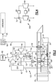
Figure 1A schematically shows an air supply system for a gas turbine engine and associated aircraft. -
Figure 1B shows an option. -
Figure 1C shows another option. -
Figure 2 shows further optional features. -
Figure 3 shows further features. -
Figure 4 shows further features. - An
aircraft 20 as shown inFigure 1A has agas turbine engine 21 with afan 22 driven by afan drive turbine 24 through aspool shaft 26. Alow pressure compressor 27 may also be driven by theturbine 24. - A
higher speed shaft 28 drives acompressor 30 and is driven by ahigh pressure turbine 32. Acombustor 34 is intermediate thecompressor 30 andturbine 32. - It should be understood that teachings of this disclosure could extend to any number of engine types for use on an aircraft. As an example, the teachings of this disclosure will benefit both commercial aircraft engines and military style engines.
- Air is tapped at 46 from an intermediate location in the
compressor 30 and cooled in aheat exchanger 48.Heat exchanger 48 is exposed to fan cooling air in aduct 50. This may be the so-called bypass duct of a large commercial engine or a third stream of a military style engine. - The tapped air having been cooled passes to a
selection valve 52.Selection valve 52 is shown with acontrol 75. It should be understood that a number of the components in the disclosed system may be provided with controls and this could all be thesame control 75, which, in at least one embodiment, might be a full authority digital electronic controller (FADEC) for the entire engine. - Air at 53 downstream of the
selection valve 52 passes through acentrifugal compressor 44.Compressor 44 is driven by agearbox 42, which may be driven by atakeoff shaft 40.Takeoff shaft 40 is illustrated driven by thespool shaft 26. However, it should be understood thetakeoff shaft 40 could also be driven by thespool shaft 28. In addition, thecompressor 44 could alternatively be driven by electric, hydraulic or fuel powered motors. In addition, aclutch 45 is shown schematically and may be open when it is not necessary to further increase the pressure of the air atline 53.Compressor 44 may alternatively be driven byshaft 85. -
Selection valve 52 may be electric, hydraulic, or fluid driven. When thecompressor 44 is turned off, thevalve 52 may be controlled to not deliver air intoline 53. -
Air 54 downstream of thecompressor 44 is delivered into a mixingchamber 56. Air from atap 60, which is higher pressure thantap 46, is also delivered into mixingchamber 56. The mixed air then passes as shown at 58 to cool thehigh pressure compressor 28 and/or theturbine 24. Alternatively, the air can pass inwardly, and toturbine 24 downstream of the combustor. - The
selection valve 52 is also shown to selectively deliver air into aline 74 leading into afuel heat exchanger 72. As shown, afuel tank 70 may deliver fuel through aheat exchanger 71 at which the fuel is heated. The fuel andheat exchanger 72 is further heated by the air inline 74. That fuel then passes into aline 76 heading to thecombustor 34. - The air downstream of the
fuel heat exchanger 72 passes across afirst turbine 78. Aline 79 downstream ofturbine 78 may be utilized to supply cabin air for theaircraft cabin 80. - A portion of the air delivered downstream of
turbine 78 may branch off and pass through aheat exchanger 82. Theair exiting turbine 78 is cold and available to use as a heat sink, and its pressure is still high.Heat exchanger 82 thus provides a cooling site at little pressure drop forturbine 84 to expand.Heat exchanger 82 can thus be used for any number of cooling purposes. That line then passes across asecond turbine 84. Air downstream of theturbine 84 may be utilized for acold loop 88. - It should be understood the air downstream of the
turbine 84 will be cooled far below the temperature of the air inline 79 due to the extra expansion. Thus, the cold loop sees cooling air with a much greater capacity for cooling. The cold loop may be utilized to cool various components such as electric controls, aircraft subsystems, mission equipment such as radar, weapons systems, and for any number of other systems on the engine. The cool loop may cool fuel asaircraft 20 loiters over an area, and use the cold fuel as a heat sink at high speed operation where the total temperature of the air will be hot so that a sink is valuable. - In another embodiment,
line 79 can be heated inheat exchanger 82, allowing control of cabin inlet temperature. The uses of the different heat exchangers means that the air further downstream of the two turbines may be at any number of relative temperatures. However, immediately downstream of the second turbine the air is at a lower temperature than the air immediately downstream of the first turbine. - Air at 90 may then be dumped overboard and at, or slightly above, ambient pressure.
- The
turbines single drive shaft 85 which passes rotation energy back into thegearbox 42. A worker in the art would understand how to connect theshaft 85 intogearbox 42 to recapture the energy. Thus, some of the energy from the expansion of the air acrossturbine - The
turbine 84 may have a flow path area that is at least ten percent larger than the flow path area ofturbine 78. -
Figure 1B shows an option wherein theturbine turbines Turbine 84A drives itsown shaft 84B andturbine 78A drives itsshaft 78B. The shafts are shown as concentric, although they could also be spaced. Further, the shafts are shown connected to drive agenerator 92. Utilizing separate shafts will provide the designer with the ability to design to an aerodynamic design point for the engine. -
Figure 1C shows that the flow capacity of either turbine can be provided with systems that can be varied to reduce any aerodynamic mismatch of the oncoming flow to the rotor speed as the flow capacity per unit area may be reduced. As an example, aninlet 98 to aturbine 94 is shown with aninlet vane 96 and thecontrol 75 may vary the angle of the inlet vane to control flow capacity per unit area. In addition, or alternatively, anoutlet 100 of theturbine 94 may be provided with adevice 102 that will restrict and reduce turbine exit flow capacity. - A worker of ordinary skill in the art would recognize when such control would be indicated.
-
Figure 2 shows anengine 120 which is similar in many respects to the engine ofFigure 1A . However, a secondaryhigh pressure tap 104 passes through avalve 106 to theheat exchanger 48. Such a tap would provide the designer with the ability to achieve higher pressure air for the several cooling uses at lower power operation. With such a system, acheck valve 109 might be indicated on the tap at 46 to prevent backflow. - In addition, another
bypass valve 110 is shown which selectively bypasses a portion of the air intoline 112 and around theturbine 78. The air will then pass intoline 83 and head toturbine 84. Note the line is shown downstream of theheat exchanger 82. - The
valve 110 can be turned to block flow through one of its downstream paths should there be a system failure. - The branch from
valve 52 tocompressor 44, and then mixingchamber 56 may be useful to cool the high pressure turbine and a back end of the high pressure compressor, for example during a hot day takeoff to control turbine and compressor temperatures. At lower power, the branch fromvalve 52 tocompressor 44, may be cut off since the engine is using less thrust. More flow toturbine 84 may be desirable to create a cold fuel reservoir for later use. Some flow tocabin 80 may be required at all times so thevalve 52 may turn off flow toline 53 but not toturbine 78 andcabin 80. - Notably, the airflow into
line 74 is preferably never shut off as thecabin 80 will always require air. -
Figure 3 shows anaircraft 220 wherein thecold loop 88 has a component 200 for cooling, and anelectronic engine control 202, and anengine bay 204. These are examples of things that may be cooled by thecold loop 88. As shown,temperature sensors 206 are associated with these locations. - The control for the
aircraft 220 may be provided with a control logic that can manipulate each of the several valves based upon the temperature at the components. Further, the control logic may be programmed to provide sufficient cooling to ensure desired component life, regulate the total system performance, and accommodate component temperature limits and life goals. -
Figure 4 shows anembodiment 300 which may be incorporated into an engine that is otherwise similar to the earlier described engine. However, avalve 302 is positioned upstream of theheat exchanger 82, and can block flow to theturbine 84. A clutch 304 would selectively disconnect theturbine 84 under such conditions. This may be generally valuable such as when the associated aircraft is in a ferry mode, and chilled fuel is not desired, but greater range would be desirable. - A method of operating an air supply system on an aircraft includes tapping a lower pressure air from at least one compressor in a gas turbine engine, and delivering the lower pressure tap air through a first heat exchanger to be cooled by cooling air, then to a selection valve. The selection valve is controlled for delivering the lower pressure tap air to a boost compressor, and delivering air downstream of the boost compressor to cool at least one turbine associated with the gas turbine engine. The selection valve also selectively delivers a portion of the lower pressure tap air across a first cooling turbine, and delivers the air downstream of the first cooling turbine to a cabin on an associated aircraft. A second portion of air downstream of the first cooling turbine is delivered across a second cooling turbine, and air downstream of the second cooling turbine is delivered for use in a cool loop.
-
Control 75 may include a processor, memory, and one or more input and/or output (I/O) device interface(s) that are communicatively coupled via a local interface. The local interface can include, for example but not limited to, one or more buses and/or other wired or wireless connections. The local interface may have additional elements, which are omitted for simplicity, such as controllers, buffers (caches), drivers, repeaters, and receivers to enable communications. Further, the local interface may include address, control, and/or data connections to enable appropriate communications among the aforementioned components. - The controller may be a hardware device for executing software, particularly software stored in memory. The processor can be a custom made or commercially available processor, a central processing unit (CPU), an auxiliary processor among several processors associated with the controller, a semiconductor based microprocessor (in the form of a microchip or chip set) or generally any device for executing software instructions.
- The memory can include any one or combination of volatile memory elements (e.g., random access memory (RAM, such as DRAM, SRAM, SDRAM, VRAM, etc.)) and/or nonvolatile memory elements (e.g., ROM, etc.). Moreover, the memory may incorporate electronic, magnetic, optical, and/or other types of storage media. The memory can also have a distributed architecture, where various components are situated remotely from one another, but can be accessed by the controller.
- The software in the memory may include one or more separate programs, each of which includes an ordered listing of executable instructions for implementing logical functions. A system component embodied as software may also be construed as a source program, executable program (object code), script, or any other entity comprising a set of instructions to be performed. When constructed as a source program, the program is translated via a compiler, assembler, interpreter, or the like, which may or may not be included within the memory.
- The input/output devices that may be coupled to system I/O Interface(s) may include input devices, for example, but not limited to, a scanner, microphone, camera, proximity device, etc. Further, the input/output devices may also include output devices, for example but not limited to a display, etc. Finally, the input/output devices may further include devices that communicate both as inputs and outputs, for instance but not limited to, a modulator/demodulator (for accessing another device, system, or network), a radio frequency (RF) or other transceiver, a bridge, a router, etc.
- When the controller is in operation, the processor can be configured to execute software stored within the memory, to communicate data to and from the memory, and to generally control operations of the computing device pursuant to the software. Software in memory, in whole or in part, is read by the processor, perhaps buffered within the processor, and then executed.
- Although an embodiment of this invention has been disclosed, a worker of ordinary skill in this art would recognize that certain modifications would come within the scope of this disclosure. For that reason, the following claims should be studied to determine the true scope and content of this disclosure.
Claims (15)
- An aircraft air supply system comprising:a gas turbine engine (20; 120; 220) including a fan (22) and at least one compressor (30), the at least one compressor (30) driven by at least one turbine (32), and a combustor (34) for combusting air from the at least one compressor (30) and delivering it across the at least one turbine (32); anda lower pressure tap (46) within the at least one compressor (30), the lower pressure tap air being connected to a first heat exchanger (48) to be cooled by cooling air, and then to a selection valve (52), the selection valve (52) configured to selectively deliver the lower pressure tap air to a boost compressor (44), and lower pressure tap air downstream of the boost compressor (44) being connected to cool the at least one turbine (32), wherein the selection valve (52) is also configured to selectively deliver a portion of the lower pressure tap air across a first cooling turbine (78), and to a line (79) associated with an air delivery system for a cabin (80) on an associated aircraft, and a portion of the air downstream of the first cooling turbine (78) being connected to a second cooling turbine (84), and air downstream of the second cooling turbine (84) being connected for use in a cold loop (88) such that the lower pressure tap air downstream of the second cooling turbine (84) is at a lower temperature than air downstream of the first cooling turbine (78).
- The aircraft air supply system as set forth in claim 1, wherein the lower pressure tap air downstream of the selection valve (52) connected to the first cooling turbine (78) is connected through a fuel heat exchanger (72), and fuel from a fuel tank (70) is connected through the fuel heat exchanger (72) to be heated by the lower pressure tap air in the line (74) heading to the first cooling turbine (78), and the fuel is then connected to the combustor (34).
- The aircraft air supply system as set forth in claim 1 or 2, wherein at least one of the first and second cooling turbines (78, 84) has a shaft (85; 84B, 78B) configured to recapture rotational energy.
- The aircraft air supply system as set forth in claim 3, wherein at least one shaft (85; 84B, 78B) from the first and second cooling turbines (78, 84) is connected into a gearbox (42), such that the rotation can be recaptured, and/or the at least one of the first and second cooling turbines (78, 84) is connected to drive a generator (92).
- The aircraft air supply system as set forth in any preceding claim, wherein the first and second cooling turbines (78, 84) rotate on a single shaft (85), or the first and second cooling turbines (78, 84) rotate on concentrically mounted shafts (78B, 84B).
- The aircraft air supply system as set forth in any preceding claim, wherein at least one of the first and second cooling turbines (78, 84) is provided with a control (75) to selectively change an effective flow area at at least one of an inlet or an outlet of the at least one of the first and second cooling turbines (78, 84).
- The aircraft air supply system as set forth in any preceding claim, wherein a clutch (45) is configured to selectively stop rotation of the boost compressor (44), and/or the selection valve (52) is configured to deliver no air to the boost compressor (44) when the boost compressor (44) is not rotating.
- The aircraft air supply system as set forth in any preceding claim, wherein there is a higher air pressure tap (104) which is connected into a mixing chamber (56) to mix with the lower pressure tap air downstream of the boost compressor (44) and mixed air downstream of the mixing chamber (56) is connected to cool the at least one turbine (32).
- The aircraft air supply system as set forth in any preceding claim, configured such that higher pressure air is tapped at a pressure higher than the lower pressure tap (46), and is connected to selectively pass through the first heat exchanger (48) when a lower power operation valve (106) is open and when the gas turbine engine (120) is operating at lower power operation, and a preventative valve (109) is placed on the lower pressure tap (46) to block flow when the lower power operation valve (106) is open.
- The aircraft air supply system as set forth in any preceding claim, wherein a bypass valve (110) is placed on the line delivering air to the first cooling turbine (78) and the bypass valve (110) is configured to selectively bypass air around the first cooling turbine (78) to a line (112) leading directly to the second cooling turbine (84).
- The aircraft air supply system as set forth in any preceding claim, wherein temperature sensors (206) are associated with components (200, 202, 204) cooled by the cool loop (88), and are configured to communicate with a control (75) for at least the selection valve (52), to control the airflow being delivered to the cold loop (88).
- A method of operating an air supply system on an aircraft comprising:tapping a lower pressure air from at least one compressor (30) in a gas turbine engine (20; 120; 220), and delivering the lower pressure tap air through a first heat exchanger (48) to be cooled by cooling air, then to a selection valve (52), controlling the selection valve (52) for delivering the lower pressure tap air to a boost compressor (44), and delivering air downstream of the boost compressor (44) to cool at least one turbine (32) associated with the gas turbine engine (20; 120; 220), the selection valve (52) also selectively delivering a first portion of the lower pressure tap air across a first cooling turbine (78), and delivering the air downstream of the first cooling turbine (78) to a cabin (80) on an associated aircraft, and a second portion of air downstream of the first cooling turbine (78) being delivered across a second cooling turbine (84), and air downstream of the second cooling turbine (84) being delivered for use in a cool loop (88).
- The method as set forth in claim 12, wherein rotational energy is recaptured from at least one of the first and second cooling turbines (78, 84), optionally the at least one of the first and second cooling turbines (78, 84):has a shaft (85; 84B; 78B) providing a drive input into a gearbox (42) for driving the boost compressor (44); and/ordriving a shaft (84B, 78B) which in turn drives a generator (92), recapturing the energy.
- The method as set forth in claim 12 or 13, further comprising tapping higher pressure air from the at least one compressor (30) and selectively delivering the higher pressure tap air to the selection valve (52) when the gas turbine engine (20; 120; 220) is at lower power operation, and blocking flow from the lower pressure tap (46) when the higher pressure air is being delivered to the selection valve (52).
- The method as set forth in claim 12, 13 or 14, further comprising selectively bypassing air leading to the first cooling turbine (78) to a line (112) leading to the second cooling turbine (84).
Applications Claiming Priority (1)
| Application Number | Priority Date | Filing Date | Title |
|---|---|---|---|
| US15/823,639 US10914242B2 (en) | 2017-11-28 | 2017-11-28 | Complex air supply system for gas turbine engine and associated aircraft |
Publications (2)
| Publication Number | Publication Date |
|---|---|
| EP3489488A1 true EP3489488A1 (en) | 2019-05-29 |
| EP3489488B1 EP3489488B1 (en) | 2021-03-31 |
Family
ID=64564563
Family Applications (1)
| Application Number | Title | Priority Date | Filing Date |
|---|---|---|---|
| EP18208970.6A Active EP3489488B1 (en) | 2017-11-28 | 2018-11-28 | Complex air supply system for gas turbine engine and associated aircraft |
Country Status (2)
| Country | Link |
|---|---|
| US (1) | US10914242B2 (en) |
| EP (1) | EP3489488B1 (en) |
Cited By (4)
| Publication number | Priority date | Publication date | Assignee | Title |
|---|---|---|---|---|
| CN110834733A (en) * | 2019-11-14 | 2020-02-25 | 中国商用飞机有限责任公司 | Air preparation system |
| EP3623290A1 (en) * | 2018-09-13 | 2020-03-18 | Hamilton Sundstrand Corporation | Two-turbine environmental control system |
| EP3702284A1 (en) * | 2019-03-01 | 2020-09-02 | Hamilton Sundstrand Corporation | Air cycle machine connected to engine gearbox |
| EP3733520A1 (en) * | 2019-04-29 | 2020-11-04 | Hamilton Sundstrand Corporation | Thermal management system with cooling turbine and generator |
Families Citing this family (16)
| Publication number | Priority date | Publication date | Assignee | Title |
|---|---|---|---|---|
| US20190255912A1 (en) * | 2018-02-19 | 2019-08-22 | Ford Global Technologies, Llc | Cabin heating system with sealed heat transfer loop |
| US11407283B2 (en) * | 2018-04-30 | 2022-08-09 | Tiger Tool International Incorporated | Cab heating systems and methods for vehicles |
| US11077949B2 (en) * | 2018-10-05 | 2021-08-03 | The Boeing Company | Dual turbine thermal management system (TMS) |
| US11993130B2 (en) | 2018-11-05 | 2024-05-28 | Tiger Tool International Incorporated | Cooling systems and methods for vehicle cabs |
| JP7120893B2 (en) * | 2018-11-20 | 2022-08-17 | 三菱重工業株式会社 | Gas turbine and its extraction amount adjustment method |
| US11293354B2 (en) * | 2019-01-17 | 2022-04-05 | Raytheon Technologies Corporation | Integrated cooling air boost compressor and fuel pump |
| US12030368B2 (en) | 2020-07-02 | 2024-07-09 | Tiger Tool International Incorporated | Compressor systems and methods for use by vehicle heating, ventilating, and air conditioning systems |
| US11486315B2 (en) * | 2020-11-06 | 2022-11-01 | Ge Aviation Systems Llc | Combustion engine including turbomachine |
| FR3120114A1 (en) * | 2021-02-25 | 2022-08-26 | Airbus Operations | AIRCRAFT WITH AN ENGINE AND A DIHYDROGEN-BASED COOLING SYSTEM |
| US11788472B2 (en) | 2021-04-14 | 2023-10-17 | Rtx Corporation | Engine bleed generators and aircraft generator systems |
| US20220364513A1 (en) * | 2021-05-14 | 2022-11-17 | Raytheon Technologies Corporation | Turbine engines having hydrogen fuel systems |
| US12044176B2 (en) * | 2021-07-09 | 2024-07-23 | Rtx Corporation | Turbine engines having hydrogen fuel systems |
| US11987377B2 (en) | 2022-07-08 | 2024-05-21 | Rtx Corporation | Turbo expanders for turbine engines having hydrogen fuel systems |
| US12103699B2 (en) | 2022-07-08 | 2024-10-01 | Rtx Corporation | Hybrid electric power for turbine engines having hydrogen fuel systems |
| EP4488499A1 (en) * | 2023-07-06 | 2025-01-08 | Rolls-Royce plc | Aircraft propulsion system |
| US12410748B1 (en) * | 2024-05-21 | 2025-09-09 | Rtx Corporation | Boost compressor augmentation for hybrid electric thermal management systems |
Citations (3)
| Publication number | Priority date | Publication date | Assignee | Title |
|---|---|---|---|---|
| EP0888966A2 (en) * | 1997-07-02 | 1999-01-07 | Boeing North American, Inc. | High efficiency environmental control systems and methods |
| US20150233291A1 (en) * | 2014-02-17 | 2015-08-20 | Airbus Operations (Sas) | Turbojet comprising a bleeding system for bleeding air in said turbojet |
| US20160312711A1 (en) * | 2015-04-24 | 2016-10-27 | United Technologies Corporation | Intercooled cooling air with plural heat exchangers |
Family Cites Families (9)
| Publication number | Priority date | Publication date | Assignee | Title |
|---|---|---|---|---|
| US5285626A (en) * | 1992-03-20 | 1994-02-15 | Woodward Governor Company | Drive for main engine auxiliaries for an aircraft gas turbine engine |
| US5488823A (en) | 1993-05-12 | 1996-02-06 | Gas Research Institute | Turbocharger-based bleed-air driven fuel gas booster system and method |
| US5392595A (en) | 1993-08-06 | 1995-02-28 | United Technologies Corporation | Endothermic fuel energy management system |
| US5452573A (en) * | 1994-01-31 | 1995-09-26 | United Technologies Corporation | High pressure air source for aircraft and engine requirements |
| US5899085A (en) * | 1997-08-01 | 1999-05-04 | Mcdonnell Douglas Corporation | Integrated air conditioning and power unit |
| AU2002250133A1 (en) * | 2001-02-16 | 2002-09-04 | Hamilton Sundstrand Corporation | Improved aircraft system architecture |
| FR2842564B1 (en) * | 2002-07-17 | 2006-01-21 | Snecma Moteurs | ASSISTANCE AND RELIEF FOR THE ELECTRICAL DRIVING OF ACCESSORIES IN A TURBOMOTEUR |
| US8967528B2 (en) * | 2012-01-24 | 2015-03-03 | The Boeing Company | Bleed air systems for use with aircrafts and related methods |
| US20160237908A1 (en) * | 2015-02-12 | 2016-08-18 | United Technologies Corporation | Intercooled cooling air using existing heat exchanger |
-
2017
- 2017-11-28 US US15/823,639 patent/US10914242B2/en active Active
-
2018
- 2018-11-28 EP EP18208970.6A patent/EP3489488B1/en active Active
Patent Citations (3)
| Publication number | Priority date | Publication date | Assignee | Title |
|---|---|---|---|---|
| EP0888966A2 (en) * | 1997-07-02 | 1999-01-07 | Boeing North American, Inc. | High efficiency environmental control systems and methods |
| US20150233291A1 (en) * | 2014-02-17 | 2015-08-20 | Airbus Operations (Sas) | Turbojet comprising a bleeding system for bleeding air in said turbojet |
| US20160312711A1 (en) * | 2015-04-24 | 2016-10-27 | United Technologies Corporation | Intercooled cooling air with plural heat exchangers |
Cited By (7)
| Publication number | Priority date | Publication date | Assignee | Title |
|---|---|---|---|---|
| EP3623290A1 (en) * | 2018-09-13 | 2020-03-18 | Hamilton Sundstrand Corporation | Two-turbine environmental control system |
| EP3702284A1 (en) * | 2019-03-01 | 2020-09-02 | Hamilton Sundstrand Corporation | Air cycle machine connected to engine gearbox |
| US11465770B2 (en) | 2019-03-01 | 2022-10-11 | Hamilton Sundstrand Corporation | Air cycle machine connected to engine gearbox |
| EP3733520A1 (en) * | 2019-04-29 | 2020-11-04 | Hamilton Sundstrand Corporation | Thermal management system with cooling turbine and generator |
| US11286857B2 (en) | 2019-04-29 | 2022-03-29 | Hamilton Sundstrand Corporation | Turbine-turbine generator power thermal management system |
| CN110834733A (en) * | 2019-11-14 | 2020-02-25 | 中国商用飞机有限责任公司 | Air preparation system |
| CN110834733B (en) * | 2019-11-14 | 2021-10-22 | 中国商用飞机有限责任公司 | air preparation system |
Also Published As
| Publication number | Publication date |
|---|---|
| US10914242B2 (en) | 2021-02-09 |
| US20190162121A1 (en) | 2019-05-30 |
| EP3489488B1 (en) | 2021-03-31 |
Similar Documents
| Publication | Publication Date | Title |
|---|---|---|
| EP3489488B1 (en) | Complex air supply system for gas turbine engine and associated aircraft | |
| EP3726027B1 (en) | Integrated thermal management system for fuel cooling | |
| US11236675B2 (en) | Gas turbine engine with intercooled cooling air and turbine drive | |
| EP4155525B1 (en) | Environmental control system air circuit | |
| JP5976397B2 (en) | Adaptive output thermal management system | |
| US8015826B2 (en) | Engine brake for part load CO reduction | |
| EP3907388A1 (en) | Engine bleed power recovery systems and related methods | |
| EP3095990B1 (en) | Gas turbine engine and method of operating the same | |
| EP2929163B1 (en) | Gas turbine engine with plural accessory air paths | |
| US10753280B2 (en) | Turbomachine designed to operate in turning gear mode | |
| EP3690213B1 (en) | Aircraft environmental control | |
| EP3287623B1 (en) | Variable speed boost compressor for gas turbine engine cooling air supply | |
| US20200300168A1 (en) | Backup system for demand fuel pumping system | |
| EP3712410A1 (en) | Mechanical demand fuel pumping system | |
| US11002187B2 (en) | Low rotor boost compressor for engine cooling circuit | |
| EP3792473A1 (en) | Fuel cooled cooling air | |
| EP3683419B1 (en) | Integrated cooling air boost compressor and fuel pump | |
| EP4553311A2 (en) | Transmission and method for control of boost spool | |
| EP3569841A1 (en) | Intercooled cooling air with heat exchanger packaging | |
| US11808210B2 (en) | Intercooled cooling air with heat exchanger packaging |
Legal Events
| Date | Code | Title | Description |
|---|---|---|---|
| PUAI | Public reference made under article 153(3) epc to a published international application that has entered the european phase |
Free format text: ORIGINAL CODE: 0009012 |
|
| STAA | Information on the status of an ep patent application or granted ep patent |
Free format text: STATUS: THE APPLICATION HAS BEEN PUBLISHED |
|
| AK | Designated contracting states |
Kind code of ref document: A1 Designated state(s): AL AT BE BG CH CY CZ DE DK EE ES FI FR GB GR HR HU IE IS IT LI LT LU LV MC MK MT NL NO PL PT RO RS SE SI SK SM TR |
|
| AX | Request for extension of the european patent |
Extension state: BA ME |
|
| STAA | Information on the status of an ep patent application or granted ep patent |
Free format text: STATUS: REQUEST FOR EXAMINATION WAS MADE |
|
| 17P | Request for examination filed |
Effective date: 20191129 |
|
| RBV | Designated contracting states (corrected) |
Designated state(s): AL AT BE BG CH CY CZ DE DK EE ES FI FR GB GR HR HU IE IS IT LI LT LU LV MC MK MT NL NO PL PT RO RS SE SI SK SM TR |
|
| GRAP | Despatch of communication of intention to grant a patent |
Free format text: ORIGINAL CODE: EPIDOSNIGR1 |
|
| STAA | Information on the status of an ep patent application or granted ep patent |
Free format text: STATUS: GRANT OF PATENT IS INTENDED |
|
| RIC1 | Information provided on ipc code assigned before grant |
Ipc: F02C 7/224 20060101ALI20200925BHEP Ipc: F02C 7/32 20060101ALI20200925BHEP Ipc: F02C 7/18 20060101ALI20200925BHEP Ipc: F02C 7/14 20060101AFI20200925BHEP |
|
| INTG | Intention to grant announced |
Effective date: 20201013 |
|
| GRAS | Grant fee paid |
Free format text: ORIGINAL CODE: EPIDOSNIGR3 |
|
| GRAA | (expected) grant |
Free format text: ORIGINAL CODE: 0009210 |
|
| STAA | Information on the status of an ep patent application or granted ep patent |
Free format text: STATUS: THE PATENT HAS BEEN GRANTED |
|
| RAP1 | Party data changed (applicant data changed or rights of an application transferred) |
Owner name: RAYTHEON TECHNOLOGIES CORPORATION |
|
| AK | Designated contracting states |
Kind code of ref document: B1 Designated state(s): AL AT BE BG CH CY CZ DE DK EE ES FI FR GB GR HR HU IE IS IT LI LT LU LV MC MK MT NL NO PL PT RO RS SE SI SK SM TR |
|
| REG | Reference to a national code |
Ref country code: GB Ref legal event code: FG4D Ref country code: CH Ref legal event code: EP |
|
| REG | Reference to a national code |
Ref country code: AT Ref legal event code: REF Ref document number: 1377187 Country of ref document: AT Kind code of ref document: T Effective date: 20210415 |
|
| REG | Reference to a national code |
Ref country code: DE Ref legal event code: R096 Ref document number: 602018014674 Country of ref document: DE |
|
| REG | Reference to a national code |
Ref country code: IE Ref legal event code: FG4D |
|
| REG | Reference to a national code |
Ref country code: LT Ref legal event code: MG9D |
|
| PG25 | Lapsed in a contracting state [announced via postgrant information from national office to epo] |
Ref country code: NO Free format text: LAPSE BECAUSE OF FAILURE TO SUBMIT A TRANSLATION OF THE DESCRIPTION OR TO PAY THE FEE WITHIN THE PRESCRIBED TIME-LIMIT Effective date: 20210630 Ref country code: BG Free format text: LAPSE BECAUSE OF FAILURE TO SUBMIT A TRANSLATION OF THE DESCRIPTION OR TO PAY THE FEE WITHIN THE PRESCRIBED TIME-LIMIT Effective date: 20210630 Ref country code: HR Free format text: LAPSE BECAUSE OF FAILURE TO SUBMIT A TRANSLATION OF THE DESCRIPTION OR TO PAY THE FEE WITHIN THE PRESCRIBED TIME-LIMIT Effective date: 20210331 Ref country code: FI Free format text: LAPSE BECAUSE OF FAILURE TO SUBMIT A TRANSLATION OF THE DESCRIPTION OR TO PAY THE FEE WITHIN THE PRESCRIBED TIME-LIMIT Effective date: 20210331 |
|
| PG25 | Lapsed in a contracting state [announced via postgrant information from national office to epo] |
Ref country code: RS Free format text: LAPSE BECAUSE OF FAILURE TO SUBMIT A TRANSLATION OF THE DESCRIPTION OR TO PAY THE FEE WITHIN THE PRESCRIBED TIME-LIMIT Effective date: 20210331 Ref country code: LV Free format text: LAPSE BECAUSE OF FAILURE TO SUBMIT A TRANSLATION OF THE DESCRIPTION OR TO PAY THE FEE WITHIN THE PRESCRIBED TIME-LIMIT Effective date: 20210331 Ref country code: SE Free format text: LAPSE BECAUSE OF FAILURE TO SUBMIT A TRANSLATION OF THE DESCRIPTION OR TO PAY THE FEE WITHIN THE PRESCRIBED TIME-LIMIT Effective date: 20210331 |
|
| REG | Reference to a national code |
Ref country code: NL Ref legal event code: MP Effective date: 20210331 |
|
| REG | Reference to a national code |
Ref country code: AT Ref legal event code: MK05 Ref document number: 1377187 Country of ref document: AT Kind code of ref document: T Effective date: 20210331 |
|
| PG25 | Lapsed in a contracting state [announced via postgrant information from national office to epo] |
Ref country code: AT Free format text: LAPSE BECAUSE OF FAILURE TO SUBMIT A TRANSLATION OF THE DESCRIPTION OR TO PAY THE FEE WITHIN THE PRESCRIBED TIME-LIMIT Effective date: 20210331 Ref country code: NL Free format text: LAPSE BECAUSE OF FAILURE TO SUBMIT A TRANSLATION OF THE DESCRIPTION OR TO PAY THE FEE WITHIN THE PRESCRIBED TIME-LIMIT Effective date: 20210331 Ref country code: SM Free format text: LAPSE BECAUSE OF FAILURE TO SUBMIT A TRANSLATION OF THE DESCRIPTION OR TO PAY THE FEE WITHIN THE PRESCRIBED TIME-LIMIT Effective date: 20210331 Ref country code: CZ Free format text: LAPSE BECAUSE OF FAILURE TO SUBMIT A TRANSLATION OF THE DESCRIPTION OR TO PAY THE FEE WITHIN THE PRESCRIBED TIME-LIMIT Effective date: 20210331 Ref country code: EE Free format text: LAPSE BECAUSE OF FAILURE TO SUBMIT A TRANSLATION OF THE DESCRIPTION OR TO PAY THE FEE WITHIN THE PRESCRIBED TIME-LIMIT Effective date: 20210331 Ref country code: LT Free format text: LAPSE BECAUSE OF FAILURE TO SUBMIT A TRANSLATION OF THE DESCRIPTION OR TO PAY THE FEE WITHIN THE PRESCRIBED TIME-LIMIT Effective date: 20210331 |
|
| PG25 | Lapsed in a contracting state [announced via postgrant information from national office to epo] |
Ref country code: IS Free format text: LAPSE BECAUSE OF FAILURE TO SUBMIT A TRANSLATION OF THE DESCRIPTION OR TO PAY THE FEE WITHIN THE PRESCRIBED TIME-LIMIT Effective date: 20210731 Ref country code: PT Free format text: LAPSE BECAUSE OF FAILURE TO SUBMIT A TRANSLATION OF THE DESCRIPTION OR TO PAY THE FEE WITHIN THE PRESCRIBED TIME-LIMIT Effective date: 20210802 Ref country code: PL Free format text: LAPSE BECAUSE OF FAILURE TO SUBMIT A TRANSLATION OF THE DESCRIPTION OR TO PAY THE FEE WITHIN THE PRESCRIBED TIME-LIMIT Effective date: 20210331 Ref country code: RO Free format text: LAPSE BECAUSE OF FAILURE TO SUBMIT A TRANSLATION OF THE DESCRIPTION OR TO PAY THE FEE WITHIN THE PRESCRIBED TIME-LIMIT Effective date: 20210331 Ref country code: SK Free format text: LAPSE BECAUSE OF FAILURE TO SUBMIT A TRANSLATION OF THE DESCRIPTION OR TO PAY THE FEE WITHIN THE PRESCRIBED TIME-LIMIT Effective date: 20210331 |
|
| REG | Reference to a national code |
Ref country code: DE Ref legal event code: R097 Ref document number: 602018014674 Country of ref document: DE |
|
| PG25 | Lapsed in a contracting state [announced via postgrant information from national office to epo] |
Ref country code: ES Free format text: LAPSE BECAUSE OF FAILURE TO SUBMIT A TRANSLATION OF THE DESCRIPTION OR TO PAY THE FEE WITHIN THE PRESCRIBED TIME-LIMIT Effective date: 20210331 Ref country code: AL Free format text: LAPSE BECAUSE OF FAILURE TO SUBMIT A TRANSLATION OF THE DESCRIPTION OR TO PAY THE FEE WITHIN THE PRESCRIBED TIME-LIMIT Effective date: 20210331 Ref country code: DK Free format text: LAPSE BECAUSE OF FAILURE TO SUBMIT A TRANSLATION OF THE DESCRIPTION OR TO PAY THE FEE WITHIN THE PRESCRIBED TIME-LIMIT Effective date: 20210331 |
|
| PLBE | No opposition filed within time limit |
Free format text: ORIGINAL CODE: 0009261 |
|
| STAA | Information on the status of an ep patent application or granted ep patent |
Free format text: STATUS: NO OPPOSITION FILED WITHIN TIME LIMIT |
|
| 26N | No opposition filed |
Effective date: 20220104 |
|
| PG25 | Lapsed in a contracting state [announced via postgrant information from national office to epo] |
Ref country code: IS Free format text: LAPSE BECAUSE OF FAILURE TO SUBMIT A TRANSLATION OF THE DESCRIPTION OR TO PAY THE FEE WITHIN THE PRESCRIBED TIME-LIMIT Effective date: 20210731 |
|
| PG25 | Lapsed in a contracting state [announced via postgrant information from national office to epo] |
Ref country code: MC Free format text: LAPSE BECAUSE OF FAILURE TO SUBMIT A TRANSLATION OF THE DESCRIPTION OR TO PAY THE FEE WITHIN THE PRESCRIBED TIME-LIMIT Effective date: 20210331 |
|
| REG | Reference to a national code |
Ref country code: CH Ref legal event code: PL |
|
| PG25 | Lapsed in a contracting state [announced via postgrant information from national office to epo] |
Ref country code: LU Free format text: LAPSE BECAUSE OF NON-PAYMENT OF DUE FEES Effective date: 20211128 Ref country code: IT Free format text: LAPSE BECAUSE OF FAILURE TO SUBMIT A TRANSLATION OF THE DESCRIPTION OR TO PAY THE FEE WITHIN THE PRESCRIBED TIME-LIMIT Effective date: 20210331 Ref country code: BE Free format text: LAPSE BECAUSE OF NON-PAYMENT OF DUE FEES Effective date: 20211130 |
|
| REG | Reference to a national code |
Ref country code: BE Ref legal event code: MM Effective date: 20211130 |
|
| PG25 | Lapsed in a contracting state [announced via postgrant information from national office to epo] |
Ref country code: IE Free format text: LAPSE BECAUSE OF NON-PAYMENT OF DUE FEES Effective date: 20211128 |
|
| P01 | Opt-out of the competence of the unified patent court (upc) registered |
Effective date: 20230521 |
|
| PG25 | Lapsed in a contracting state [announced via postgrant information from national office to epo] |
Ref country code: CY Free format text: LAPSE BECAUSE OF FAILURE TO SUBMIT A TRANSLATION OF THE DESCRIPTION OR TO PAY THE FEE WITHIN THE PRESCRIBED TIME-LIMIT Effective date: 20210331 |
|
| PG25 | Lapsed in a contracting state [announced via postgrant information from national office to epo] |
Ref country code: LI Free format text: LAPSE BECAUSE OF NON-PAYMENT OF DUE FEES Effective date: 20220630 Ref country code: HU Free format text: LAPSE BECAUSE OF FAILURE TO SUBMIT A TRANSLATION OF THE DESCRIPTION OR TO PAY THE FEE WITHIN THE PRESCRIBED TIME-LIMIT; INVALID AB INITIO Effective date: 20181128 Ref country code: GR Free format text: LAPSE BECAUSE OF FAILURE TO SUBMIT A TRANSLATION OF THE DESCRIPTION OR TO PAY THE FEE WITHIN THE PRESCRIBED TIME-LIMIT Effective date: 20210331 Ref country code: CH Free format text: LAPSE BECAUSE OF NON-PAYMENT OF DUE FEES Effective date: 20220630 |
|
| PG25 | Lapsed in a contracting state [announced via postgrant information from national office to epo] |
Ref country code: MK Free format text: LAPSE BECAUSE OF FAILURE TO SUBMIT A TRANSLATION OF THE DESCRIPTION OR TO PAY THE FEE WITHIN THE PRESCRIBED TIME-LIMIT Effective date: 20210331 |
|
| PG25 | Lapsed in a contracting state [announced via postgrant information from national office to epo] |
Ref country code: TR Free format text: LAPSE BECAUSE OF FAILURE TO SUBMIT A TRANSLATION OF THE DESCRIPTION OR TO PAY THE FEE WITHIN THE PRESCRIBED TIME-LIMIT Effective date: 20210331 |
|
| PG25 | Lapsed in a contracting state [announced via postgrant information from national office to epo] |
Ref country code: MT Free format text: LAPSE BECAUSE OF FAILURE TO SUBMIT A TRANSLATION OF THE DESCRIPTION OR TO PAY THE FEE WITHIN THE PRESCRIBED TIME-LIMIT Effective date: 20210331 |
|
| REG | Reference to a national code |
Ref country code: DE Ref legal event code: R081 Ref document number: 602018014674 Country of ref document: DE Owner name: RTX CORPORATION (N.D.GES.D. STAATES DELAWARE),, US Free format text: FORMER OWNER: RAYTHEON TECHNOLOGIES CORPORATION, FARMINGTON, CT, US |
|
| PGFP | Annual fee paid to national office [announced via postgrant information from national office to epo] |
Ref country code: DE Payment date: 20251022 Year of fee payment: 8 |
|
| PGFP | Annual fee paid to national office [announced via postgrant information from national office to epo] |
Ref country code: GB Payment date: 20251022 Year of fee payment: 8 |
|
| PGFP | Annual fee paid to national office [announced via postgrant information from national office to epo] |
Ref country code: FR Payment date: 20251022 Year of fee payment: 8 |