EP3489419B1 - Stabilizer leg arrangement and mobile working machine comprising such a stabilizer leg arrangement - Google Patents
Stabilizer leg arrangement and mobile working machine comprising such a stabilizer leg arrangement Download PDFInfo
- Publication number
- EP3489419B1 EP3489419B1 EP17203692.3A EP17203692A EP3489419B1 EP 3489419 B1 EP3489419 B1 EP 3489419B1 EP 17203692 A EP17203692 A EP 17203692A EP 3489419 B1 EP3489419 B1 EP 3489419B1
- Authority
- EP
- European Patent Office
- Prior art keywords
- stabilizer leg
- extension
- support beam
- entrance opening
- working machine
- Prior art date
- Legal status (The legal status is an assumption and is not a legal conclusion. Google has not performed a legal analysis and makes no representation as to the accuracy of the status listed.)
- Active
Links
Images
Classifications
-
- B—PERFORMING OPERATIONS; TRANSPORTING
- B66—HOISTING; LIFTING; HAULING
- B66C—CRANES; LOAD-ENGAGING ELEMENTS OR DEVICES FOR CRANES, CAPSTANS, WINCHES, OR TACKLES
- B66C23/00—Cranes comprising essentially a beam, boom, or triangular structure acting as a cantilever and mounted for translatory of swinging movements in vertical or horizontal planes or a combination of such movements, e.g. jib-cranes, derricks, tower cranes
- B66C23/62—Constructional features or details
- B66C23/72—Counterweights or supports for balancing lifting couples
- B66C23/78—Supports, e.g. outriggers, for mobile cranes
- B66C23/80—Supports, e.g. outriggers, for mobile cranes hydraulically actuated
-
- B—PERFORMING OPERATIONS; TRANSPORTING
- B66—HOISTING; LIFTING; HAULING
- B66C—CRANES; LOAD-ENGAGING ELEMENTS OR DEVICES FOR CRANES, CAPSTANS, WINCHES, OR TACKLES
- B66C23/00—Cranes comprising essentially a beam, boom, or triangular structure acting as a cantilever and mounted for translatory of swinging movements in vertical or horizontal planes or a combination of such movements, e.g. jib-cranes, derricks, tower cranes
- B66C23/88—Safety gear
- B66C23/90—Devices for indicating or limiting lifting moment
- B66C23/905—Devices for indicating or limiting lifting moment electrical
-
- E—FIXED CONSTRUCTIONS
- E02—HYDRAULIC ENGINEERING; FOUNDATIONS; SOIL SHIFTING
- E02F—DREDGING; SOIL-SHIFTING
- E02F9/00—Component parts of dredgers or soil-shifting machines, not restricted to one of the kinds covered by groups E02F3/00 - E02F7/00
- E02F9/08—Superstructures; Supports for superstructures
- E02F9/085—Ground-engaging fitting for supporting the machines while working, e.g. outriggers, legs
Definitions
- the present invention relates to a stabilizer leg arrangement according to the preamble of claim 1 for supporting a mobile working machine against the ground.
- the invention also relates to a mobile working machine according to the preamble of claim 6.
- a mobile working machine for instance in the form of a vehicle having a hydraulic crane mounted on its chassis, is often provided with hydraulically actuated stabilizer legs for supporting the working machine against the ground to thereby improve the stability of the working machine. If such a working machine is provided with a system for monitoring the stability of the working machine, there might be a need to establish the magnitude of the support forces acting on the stabilizer legs when they are in supporting contact with the ground.
- the differential pressure in the hydraulic cylinder depends on the support force acting on the stabilizer leg when it is in supporting contact with the ground.
- the differential pressure in the hydraulic cylinder of such a stabilizer leg may be established based on measuring signals from a first pressure sensor configured to sense the hydraulic pressure on the piston side of the hydraulic cylinder and a from a second pressure sensor configured to sense the hydraulic pressure on the piston rod side of the hydraulic cylinder, and the magnitude of the support force acting on the stabilizer leg when it is in supporting contact with the ground may then be established based on the value of the differential pressure.
- a high differential pressure resembling the differential pressure caused by a support force on the stabilizer leg may also be developed in the hydraulic cylinder when it has reached its extended end position before the stabilizer leg makes contact with the ground.
- a measuring system that is configured to use measuring values as to the differential pressure in the hydraulic cylinder of a stabilizer leg in order to establish the magnitude of the support force acting on the stabilizer leg also has to include an additional sensor for detecting whether or not the hydraulic cylinder is in its extended end position.
- the arrangement of a force sensor in or close to the foot plate also implies that the force sensor has to move together with the foot plate in both horizontal and vertical directions in connection with a movement of the stabilizer leg from its inactive resting position to its active operating position, which puts high demands on the cable connection between the force sensor and the electronic processing device that is configured to receive the measuring values from the force sensor.
- JP H07 285786 A discloses an X-type outrigger arrangement.
- the hydraulic pressure in the pivoting cylinder is measured and, using this value, the ground reaction force is calculated.
- JP H11 246176 A discloses a stabilizer leg arrangement according to the preamble of claim 1.
- the object of the present invention is to provide a new and favourable manner of establishing the magnitude of the support force acting on a stabilizer leg when supporting a mobile working machine against the ground.
- the stabilizer leg arrangement according to the present invention comprises:
- the magnitude of the support force acting on the stabilizer leg may be established in a simple manner by means of a low number of sensors and without requiring any use of a sensor mounted to a moveable part of the extension arm or to the stabilizer leg.
- all the required sensors may be fixed to the support beam, which implies a reduced risk for damages to the sensors and makes it possible for the sensors to be connected to the electronic processing device in a simple and reliable manner.
- the invention also relates to a mobile working machine having the features defined in claim 6.
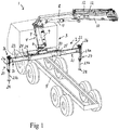
- Fig 1 schematically illustrates a mobile working machine 1 provided with a stabilizer leg arrangement 2 according to an embodiment of the present invention, wherein the stabilizer leg arrangement 2 is to be used for supporting the mobile working machine against the ground.
- the mobile working machine 1 is a crane vehicle comprising a vehicle 3 and a hydraulic crane 4.
- the crane 4 is mounted to a base structure 5 of the mobile working machine 1.
- said base structure 5 constitutes the chassis of the vehicle 3.
- the illustrated crane 4 comprises:
- the above-mentioned second crane boom 10 is telescopically extensible by means of a number of hydraulic cylinders 12 in order to enable an adjustment of the extension length thereof.
- the stabilizer leg arrangement 2 comprises a support beam 20 fixedly connected to a base structure 5 of the mobile working machine 1, i.e. to the chassis of the vehicle 3 included in the mobile working machine 1.
- the support beam 20 is rigidly mounted to the crane base 6, wherein the support beam 20 is fixedly connected to the base structure 5 of the mobile working machine 1 via the crane base 6.
- the support beam 20 may as an alternative be mounted directly to the base structure 5 of the mobile working machine 1.
- each extension arm 21 is mounted to the support beam 20 on opposite sides thereof.
- Each extension arm 21 is telescopically extensible in order to allow an adjustment of the horizontal extension length thereof.
- Each extension arm 21 comprises at least a first extension beam 22 which is telescopically mounted to the support beam 20 so as to be axially slidable in relation to the support beam 20 in the longitudinal direction of the extension arm 21 in order to vary the horizontal extension length thereof.
- This first extension beam 22 extends into an interior space 23 (see Figs 2 and 3 ) of the support beam 20 through an entrance opening 24 provided at an end of the support beam.
- a reinforcement collar 25, which forms part of the support beam 20, is arranged around each entrance opening 24.
- the reinforcement collar 25 extends around the rim of the associated entrance opening 24 and is arranged in a plane perpendicular to the longitudinal axis of the support beam 20.
- the first extension beam 22 is horizontally moveable in relation to the support beam 20 by means of a hydraulic cylinder (not shown) or any other suitable type of linear actuator.
- Each extension arm 21 may also comprise a further extension beam which is telescopically mounted to the first extension beam 22 so as to be axially slidable in relation to the first extension beam.
- each extension arm 21 comprises only one extension beam 22.
- a stabilizer leg 26 is mounted to each extension arm 21 at an outer end thereof, wherein the stabilizer leg 26 is extensible in a vertical direction by means of an actuator 27.
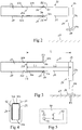
- Each stabilizer leg 26 comprises a foot plate 28, which is arranged at a lower end of the stabilizer leg so as to be vertically moveable, by a vertical extension of the stabilizer leg 26 under the effect of the actuator 27, from a raised non-use position (see Fig 2 ), in which the foot plate 28 is lifted from the ground 29, to a lowered operating position (see Fig 3 ), in which the foot plate 28 is in supporting contact with the ground 29.
- the actuator 27 of each stabilizer leg 26 has the form of a hydraulic cylinder with a cylinder part 27a, which forms an upper part of the stabilizer leg, and a piston rod 27b, which forms a lower part of the stabilizer leg.
- the piston rod 27b is at its upper end fixed to a piston (not shown), which is received in the cylinder part 27a and displaceable in relation to it.
- the foot plate 28 is fixed to the lower end of the piston rod 27b.
- the external cross-sectional shape of the first extension beam 22 is somewhat smaller than the internal cross-sectional shape of the entrance opening 24 and the internal cross-sectional shape of the interior space 23 of the support beam 20.
- the first extension beam 22 is slightly inclined downwards as seen from the rear end 22a of the first extension beam towards the front end thereof, wherein the bottom surface 30a of the first extension beam 22 abuts against the lower edge 31a of the entrance opening 24 and the upper surface 30b of the first extension beam 22 abuts against the upper surface 32b of the interior space 23 of the support beam 20 at the rear end 22a of the first extension beam 22.
- the first extension beam 22 is slightly inclined upwards as seen from the rear end 22a of the first extension beam 22 towards the front end thereof, wherein the upper surface 30b of the first extension beam 22 abuts against the upper edge 31b of the entrance opening 24 and the bottom surface 30a of the first extension beam 22 abuts against the bottom surface 32a of the interior space 23 of the support beam 20 at the rear end 22a of the first extension beam 22.
- the stabilizer leg arrangement 2 further comprises a measuring system 40 (very schematically illustrated in Fig 5 ) for establishing the magnitude of the support force F3 acting on the foot plate 28 of each stabilizer leg 26 when the foot plate is in the operating position in contact with the ground 29.
- the support force F3 corresponds to the contact force between the ground 29 and the foot plate 28.
- the measuring system 40 comprises a length measuring device 41 configured to generate a first measuring value that depends on the extension length of the extension arm 21.
- the length measuring device 41 is configured to emit a measuring signal that varies in dependence on the extension length of the extension arm 21.
- the length measuring device 41 is preferably of a type which utilizes a noncontact measurement technique.
- the length measuring device 41 is for instance of magnetoresistive type or laser type. However, an electromechanical length measuring device or a length measuring device of any other suitable type may also be used.
- the measuring system 40 also comprises a force sensor 42 which is arranged on the support beam 20 in the vicinity of the entrance opening 24 and which is configured to generate a second measuring value that depends on the contact force F2 between the first extension beam 22 and the support beam 20 at the entrance opening 24.
- this force sensor 42 is configured to emit a measuring signal that varies in dependence on the contact force F2.
- the force sensor 42 preferably comprises one or more strain gauges configured to sense the strain on a part of the support beam 20 in the vicinity of the entrance opening 24 caused by the contact force F2.
- the strain on the support beam 20 in the vicinity of the entrance opening 24 has a magnitude that depends on the magnitude of the contact force F2, and the magnitude of the contact force F2 can thereby be derived from the magnitude of said strain.
- the force sensor 42 may as an alternative be a piezoresistive force sensor or a force sensor of any other suitable type.
- the force sensor 42 is with advantage arranged on the reinforcement collar 25, as illustrated in Fig 4 , but it may as an alternative be arranged on a lateral wall of the support beam 20 close to the entrance opening 24.
- the length measuring device 41 and the force sensor 42 are connected to an electronic processing device 43, which is configured to receive the above-mentioned first and second measuring values from the length measuring device 41 and the force sensor 42.
- the contact forces acting on the foot plate 28 and on the first extension beam 22 when the foot plate 28 is in the lowered operating position are illustrated in Fig 3 .
- the foot plate 28 is subjected to an upwardly directed contact force at the interface between the foot plate and the ground 29, i.e. the support force F3
- the first extension beam 22 is subjected to a downwardly directed contact force F2 at the interface between the first extension beam and the upper edge 31b of the entrance opening 24 and an upwardly directed contact force F1 at the interface between the first extension beam 22 and the bottom surface 32a of the interior space 23 of the support beam 20.
- the electronic processing device 43 To establish the magnitude of the support force F3 based on the formula [4] above and the first and second measuring values from the length measuring device 41 and the force sensor related to L2 and F2.
Landscapes
- Engineering & Computer Science (AREA)
- Mechanical Engineering (AREA)
- Mining & Mineral Resources (AREA)
- Civil Engineering (AREA)
- General Engineering & Computer Science (AREA)
- Structural Engineering (AREA)
- Vehicle Cleaning, Maintenance, Repair, Refitting, And Outriggers (AREA)
Description
- The present invention relates to a stabilizer leg arrangement according to the preamble of claim 1 for supporting a mobile working machine against the ground. The invention also relates to a mobile working machine according to the preamble of
claim 6. - A mobile working machine, for instance in the form of a vehicle having a hydraulic crane mounted on its chassis, is often provided with hydraulically actuated stabilizer legs for supporting the working machine against the ground to thereby improve the stability of the working machine. If such a working machine is provided with a system for monitoring the stability of the working machine, there might be a need to establish the magnitude of the support forces acting on the stabilizer legs when they are in supporting contact with the ground.
- For a stabilizer leg provided with an actuator in the form of a hydraulic cylinder for extending the stabilizer leg vertically downwards into contact with the ground, the differential pressure in the hydraulic cylinder depends on the support force acting on the stabilizer leg when it is in supporting contact with the ground. The differential pressure in the hydraulic cylinder of such a stabilizer leg may be established based on measuring signals from a first pressure sensor configured to sense the hydraulic pressure on the piston side of the hydraulic cylinder and a from a second pressure sensor configured to sense the hydraulic pressure on the piston rod side of the hydraulic cylinder, and the magnitude of the support force acting on the stabilizer leg when it is in supporting contact with the ground may then be established based on the value of the differential pressure. However, a high differential pressure resembling the differential pressure caused by a support force on the stabilizer leg may also be developed in the hydraulic cylinder when it has reached its extended end position before the stabilizer leg makes contact with the ground. Thus, in order to avoid an erroneous detection of a support force on a stabilizer leg, a measuring system that is configured to use measuring values as to the differential pressure in the hydraulic cylinder of a stabilizer leg in order to establish the magnitude of the support force acting on the stabilizer leg also has to include an additional sensor for detecting whether or not the hydraulic cylinder is in its extended end position. Thus, a large number of sensors are required with this previously known solution.
- It is also previously known to establish the magnitude of the support force acting on a stabilizer leg based on measuring values from a force sensor located in or close to a foot plate of the stabilizer leg. Such a solution is for instance disclosed in
US 7 012 540 B2 andDE 102016104592 A1 . A disadvantage with this type of solution is that the force sensor is located close to the ground when the stabilizer leg is in use, which implies an increased risk for damages to the force sensor. The arrangement of a force sensor in or close to the foot plate also implies that the force sensor has to move together with the foot plate in both horizontal and vertical directions in connection with a movement of the stabilizer leg from its inactive resting position to its active operating position, which puts high demands on the cable connection between the force sensor and the electronic processing device that is configured to receive the measuring values from the force sensor. -
JP H07 285786 A -
JP H11 246176 A - The object of the present invention is to provide a new and favourable manner of establishing the magnitude of the support force acting on a stabilizer leg when supporting a mobile working machine against the ground.
- According to the present invention, said object is achieved by means of a stabilizer leg arrangement having the features defined in claim 1.
- The stabilizer leg arrangement according to the present invention comprises:
- a support beam to be fixedly connected to a base structure of a mobile working machine;
- an extension arm mounted to the support beam, the extension arm being telescopically extensible in order to allow an adjustment of the horizontal extension length thereof, wherein the extension arm comprises an extension beam which is telescopically mounted to the support beam so as to be axially slidable in relation to the support beam in the longitudinal direction of the extension arm in order to vary the horizontal extension length thereof, and wherein this extension beam extends into an interior space of the support beam through an entrance opening provided at an end of the support beam;
- a stabilizer leg mounted to the extension arm at an outer end thereof, the stabilizer leg being extensible in a vertical direction by means of an actuator, wherein a foot plate is arranged at a lower end of the stabilizer leg so as to be vertically moveable, by a vertical extension of the stabilizer leg under the effect of the actuator, from a raised position, in which the foot plate is lifted from the ground, to a lowered operating position, in which the foot plate is in supporting contact with the ground; and
- a measuring system for establishing the magnitude of the support force acting on said foot plate in the operating position, wherein the measuring system comprises:
- a length measuring device configured to generate a first measuring value that depends on the extension length of the extension arm;
- a force sensor which is arranged on the support beam in the vicinity of the entrance opening and which is configured to generate a second measuring value that depends on the contact force between said extension beam and the support beam at the entrance opening; and
- an electronic processing device configured to establish the magnitude of the support force based on said first and second measuring values.
- With a measuring system of the above-mentioned type, the magnitude of the support force acting on the stabilizer leg may be established in a simple manner by means of a low number of sensors and without requiring any use of a sensor mounted to a moveable part of the extension arm or to the stabilizer leg. On the contrary, all the required sensors may be fixed to the support beam, which implies a reduced risk for damages to the sensors and makes it possible for the sensors to be connected to the electronic processing device in a simple and reliable manner.
- Further advantageous features of the stabilizer leg arrangement according to the present invention will appear from the description following below and the dependent claims.
- The invention also relates to a mobile working machine having the features defined in
claim 6. - Further advantageous features of the mobile working machine according to the present invention will appear from the description following below and the dependent claims.
- The invention will in the following be more closely described by means of embodiment examples, with reference to the appended drawings. In the drawings:
- Fig 1
- is a schematic perspective view of a mobile working machine provided with a hydraulic crane and a stabilizer leg arrangement according to an embodiment of the present invention,
- Fig 2
- is a partly cut outline diagram of parts included in a stabilizer leg arrangement according to an embodiment of the invention, with the stabilizer leg shown in a raised non-use position,
- Fig 3
- is a partly cut outline diagram corresponding to
Fig 2 , with the stabilizer leg shown in a lowered operating position, - Fig 4
- is a schematic section according to the line IV-IV in
Fig 2 , and - Fig 5
- is an outline diagram of a measuring system included in a stabilizer leg arrangement according to the invention.
-
Fig 1 schematically illustrates a mobile working machine 1 provided with a stabilizer leg arrangement 2 according to an embodiment of the present invention, wherein the stabilizer leg arrangement 2 is to be used for supporting the mobile working machine against the ground. In the illustrated example, the mobile working machine 1 is a crane vehicle comprising avehicle 3 and ahydraulic crane 4. Thecrane 4 is mounted to abase structure 5 of the mobile working machine 1. In the illustrated example, saidbase structure 5 constitutes the chassis of thevehicle 3. - The illustrated
crane 4 comprises: - a
crane base 6, which is fixed to the chassis of thevehicle 3; - a
crane column 7 which is rotatably mounted to thecrane base 6 so as to be rotatable in relation to the crane base about an essentially vertical axis of rotation; - a liftable and lowerable
first crane boom 8, which is articulately connected to thecrane column 7 in such a manner that it is pivotable in relation to the crane column about an essentially horizontal axis of rotation; - a first hydraulic cylinder 9 for lifting and lowering the
first crane boom 8 in relation to thecrane column 7; - a liftable and lowerable
second crane boom 10, which is articulately connected to thefirst crane boom 8 in such a manner that it is pivotable in relation to thefirst crane boom 8 about an essentially horizontal axis of rotation; and - a second hydraulic cylinder 11 for lifting and lowering the
second crane boom 10 in relation to thefirst crane boom 8. - The above-mentioned
second crane boom 10 is telescopically extensible by means of a number ofhydraulic cylinders 12 in order to enable an adjustment of the extension length thereof. - The stabilizer leg arrangement 2 comprises a
support beam 20 fixedly connected to abase structure 5 of the mobile working machine 1, i.e. to the chassis of thevehicle 3 included in the mobile working machine 1. In the embodiment illustrated inFig 1 , thesupport beam 20 is rigidly mounted to thecrane base 6, wherein thesupport beam 20 is fixedly connected to thebase structure 5 of the mobile working machine 1 via thecrane base 6. However, thesupport beam 20 may as an alternative be mounted directly to thebase structure 5 of the mobile working machine 1. - In embodiment illustrated in
Fig 1 , twoextension arms 21 are mounted to thesupport beam 20 on opposite sides thereof. Eachextension arm 21 is telescopically extensible in order to allow an adjustment of the horizontal extension length thereof. Eachextension arm 21 comprises at least afirst extension beam 22 which is telescopically mounted to thesupport beam 20 so as to be axially slidable in relation to thesupport beam 20 in the longitudinal direction of theextension arm 21 in order to vary the horizontal extension length thereof. Thisfirst extension beam 22 extends into an interior space 23 (seeFigs 2 and 3 ) of thesupport beam 20 through anentrance opening 24 provided at an end of the support beam. Areinforcement collar 25, which forms part of thesupport beam 20, is arranged around eachentrance opening 24. Thereinforcement collar 25 extends around the rim of the associated entrance opening 24 and is arranged in a plane perpendicular to the longitudinal axis of thesupport beam 20. Thefirst extension beam 22 is horizontally moveable in relation to thesupport beam 20 by means of a hydraulic cylinder (not shown) or any other suitable type of linear actuator. Eachextension arm 21 may also comprise a further extension beam which is telescopically mounted to thefirst extension beam 22 so as to be axially slidable in relation to the first extension beam. However, in the illustrated embodiment, eachextension arm 21 comprises only oneextension beam 22. - A
stabilizer leg 26 is mounted to eachextension arm 21 at an outer end thereof, wherein thestabilizer leg 26 is extensible in a vertical direction by means of anactuator 27. Eachstabilizer leg 26 comprises afoot plate 28, which is arranged at a lower end of the stabilizer leg so as to be vertically moveable, by a vertical extension of thestabilizer leg 26 under the effect of theactuator 27, from a raised non-use position (seeFig 2 ), in which thefoot plate 28 is lifted from theground 29, to a lowered operating position (seeFig 3 ), in which thefoot plate 28 is in supporting contact with theground 29. - In the illustrated embodiment, the
actuator 27 of eachstabilizer leg 26 has the form of a hydraulic cylinder with acylinder part 27a, which forms an upper part of the stabilizer leg, and a piston rod 27b, which forms a lower part of the stabilizer leg. The piston rod 27b is at its upper end fixed to a piston (not shown), which is received in thecylinder part 27a and displaceable in relation to it. Thefoot plate 28 is fixed to the lower end of the piston rod 27b. - The external cross-sectional shape of the
first extension beam 22 is somewhat smaller than the internal cross-sectional shape of theentrance opening 24 and the internal cross-sectional shape of theinterior space 23 of thesupport beam 20. - When the
foot plate 28 of astabilizer leg 26 is in the raised non-use position illustrated inFig 2 , thefirst extension beam 22 is slightly inclined downwards as seen from therear end 22a of the first extension beam towards the front end thereof, wherein thebottom surface 30a of thefirst extension beam 22 abuts against thelower edge 31a of theentrance opening 24 and theupper surface 30b of thefirst extension beam 22 abuts against the upper surface 32b of theinterior space 23 of thesupport beam 20 at therear end 22a of thefirst extension beam 22. There is consequently, in this situation, a small gap between theupper surface 30b of thefirst extension beam 22 and the upper edge 31b of the entrance opening 24 as well as between thebottom surface 30a of first theextension beam 22 and thebottom surface 32a of theinterior space 23 of thesupport beam 20. - When the
foot plate 28 of astabilizer leg 26 is in the lowered operating position illustrated inFig 3 , thefirst extension beam 22 is slightly inclined upwards as seen from therear end 22a of thefirst extension beam 22 towards the front end thereof, wherein theupper surface 30b of thefirst extension beam 22 abuts against the upper edge 31b of theentrance opening 24 and thebottom surface 30a of thefirst extension beam 22 abuts against thebottom surface 32a of theinterior space 23 of thesupport beam 20 at therear end 22a of thefirst extension beam 22. There is consequently, in this situation, a small gap between thebottom surface 30a of thefirst extension beam 22 and thelower edge 31a of the entrance opening 24 as well as between theupper surface 30b of thefirst extension beam 22 and the upper surface 32b of theinterior space 23 of thesupport beam 20. - The stabilizer leg arrangement 2 further comprises a measuring system 40 (very schematically illustrated in
Fig 5 ) for establishing the magnitude of the support force F3 acting on thefoot plate 28 of eachstabilizer leg 26 when the foot plate is in the operating position in contact with theground 29. The support force F3 corresponds to the contact force between theground 29 and thefoot plate 28. The measuringsystem 40 comprises a length measuring device 41 configured to generate a first measuring value that depends on the extension length of theextension arm 21. Thus, the length measuring device 41 is configured to emit a measuring signal that varies in dependence on the extension length of theextension arm 21. The length measuring device 41 is preferably of a type which utilizes a noncontact measurement technique. The length measuring device 41 is for instance of magnetoresistive type or laser type. However, an electromechanical length measuring device or a length measuring device of any other suitable type may also be used. - The measuring
system 40 also comprises aforce sensor 42 which is arranged on thesupport beam 20 in the vicinity of theentrance opening 24 and which is configured to generate a second measuring value that depends on the contact force F2 between thefirst extension beam 22 and thesupport beam 20 at theentrance opening 24. Thus, thisforce sensor 42 is configured to emit a measuring signal that varies in dependence on the contact force F2. Theforce sensor 42 preferably comprises one or more strain gauges configured to sense the strain on a part of thesupport beam 20 in the vicinity of the entrance opening 24 caused by the contact force F2. The strain on thesupport beam 20 in the vicinity of theentrance opening 24 has a magnitude that depends on the magnitude of the contact force F2, and the magnitude of the contact force F2 can thereby be derived from the magnitude of said strain. Theforce sensor 42 may as an alternative be a piezoresistive force sensor or a force sensor of any other suitable type. Theforce sensor 42 is with advantage arranged on thereinforcement collar 25, as illustrated inFig 4 , but it may as an alternative be arranged on a lateral wall of thesupport beam 20 close to theentrance opening 24. - The length measuring device 41 and the
force sensor 42 are connected to anelectronic processing device 43, which is configured to receive the above-mentioned first and second measuring values from the length measuring device 41 and theforce sensor 42. - The contact forces acting on the
foot plate 28 and on thefirst extension beam 22 when thefoot plate 28 is in the lowered operating position are illustrated inFig 3 . Thefoot plate 28 is subjected to an upwardly directed contact force at the interface between the foot plate and theground 29, i.e. the support force F3, whereas thefirst extension beam 22 is subjected to a downwardly directed contact force F2 at the interface between the first extension beam and the upper edge 31b of theentrance opening 24 and an upwardly directed contact force F1 at the interface between thefirst extension beam 22 and thebottom surface 32a of theinterior space 23 of thesupport beam 20. Equilibrium of moments about the point of contact between thefirst extension beam 22 and thesupport beam 20 at theentrance opening 24 will give the following relationship:
- F1 is the contact force between the
first extension beam 22 and thesupport beam 20 at therear end 22a of the first extension beam, - F3 is the support force,
- L2 is the horizontal distance between the
entrance opening 24 and the centre axis of thestabilizer leg 26, which essentially corresponds to the extension length of theextension arm 21, and - L1 is the horizontal distance between the
entrance opening 24 and therear end 22a of thefirst extension beam 22. - Also the following relationships can be concluded from
Fig 3 :

first extension beam 22 and thesupport beam 20 at theentrance opening 24 and L is the horizontal distance between therear end 22a of thefirst extension beam 22 and the centre axis of thestabilizer leg 26. In the illustrated example, the distance L essentially corresponds to the length of thefirst extension beam 22. - From the above-mentioned relationships [1], [2] and [3] it follows that:

- In view of the fact that the distance L has a known value, it will be possible for the
electronic processing device 43 to establish the magnitude of the support force F3 based on the formula [4] above and the first and second measuring values from the length measuring device 41 and the force sensor related to L2 and F2. - The invention is of course not in any way limited to the embodiments described above. On the contrary, several possibilities to modifications thereof should be apparent to a person skilled in the art without thereby deviating from the scope of the invention as defined in the appended claims.
Claims (7)
- A stabilizer leg arrangement for supporting a mobile working machine (1) against the ground, the stabilizer leg arrangement (2) comprising:- a support beam (20) to be fixedly connected to a base structure (5) of the mobile working machine (1);- an extension arm (21) mounted to the support beam (20), the extension arm (21) being telescopically extensible in order to allow an adjustment of the horizontal extension length thereof, wherein the extension arm (21) comprises an extension beam (22) which is telescopically mounted to the support beam (20) so as to be axially slidable in relation to the support beam (20) in the longitudinal direction of the extension arm (21) in order to vary the horizontal extension length thereof, and wherein this extension beam (22) extends into an interior space (23) of the support beam (20) through an entrance opening (24) provided at an end of the support beam;- a stabilizer leg (26) mounted to the extension arm (21) at an outer end thereof, the stabilizer leg (26) being extensible in a vertical direction by means of an actuator (27), wherein a foot plate (28) is arranged at a lower end of the stabilizer leg (26) so as to be vertically moveable, by a vertical extension of the stabilizer leg (26) under the effect of the actuator (27), from a raised position, in which the foot plate (28) is lifted from the ground, to a lowered operating position, in which the foot plate (28) is in supporting contact with the ground; and- a measuring system (40) for establishing the magnitude of the support force (F3) acting on said foot plate (28) in the operating position,characterized in that the measuring system (40) comprises:- a length measuring device (41) configured to generate a first measuring value that depends on the extension length of the extension arm (21);- a force sensor (42) which is arranged on the support beam (20) in the vicinity of the entrance opening (24) and which is configured to generate a second measuring value that depends on the contact force (F2) between said extension beam (22) and the support beam (20) at the entrance opening (24); and- an electronic processing device (43) configured to establish the magnitude of the support force (F3) based on said first and second measuring values.
- A stabilizer leg arrangement according to claim 1, characterized in that the support beam (20) comprises a reinforcement collar (25) arranged around the entrance opening (24), wherein said force sensor (42) is arranged on the reinforcement collar (25).
- A stabilizer leg arrangement according to claim 1 or 2, characterized in that said force sensor (42) comprises one or more strain gauges configured to sense the strain on a part of the support beam (20) in the vicinity of the entrance opening (24) caused by the contact force (F2) between said extension beam (22) and the support beam (20) at the entrance opening (24).
- A stabilizer leg arrangement according to any of claims 1-3, characterized in that the actuator (27) is a hydraulic cylinder.
- A stabilizer leg arrangement according to any of claims 1-4, characterized in that the electronic processing device (43) is configured to establish the magnitude of the support force (F3) based on the following formula:
 - F3 is the support force,- F2 is the the contact force between said extension beam (22) and the support beam (20) at the entrance opening (24),- L is the horizontal distance between a rear end (22a) of the said extension beam (22) and the centre axis of the stabilizer leg (26), and- L2 is the horizontal distance between the entrance opening (24) and the centre axis of the stabilizer leg (26).
 - A mobile working machine comprising a vehicle (3) with a chassis, characterized in that the mobile working machine (1) comprises a stabilizer leg arrangement (2) according to any of claims 1-5, wherein the support beam (20) of the stabilizer leg arrangement (2) is fixedly connected to the chassis of the vehicle.
- A mobile working machine according to claim 6, characterized in that the mobile working machine (1) comprises a hydraulic crane (6) mounted to the chassis of the vehicle.
Priority Applications (3)
| Application Number | Priority Date | Filing Date | Title |
|---|---|---|---|
| DK17203692.3T DK3489419T3 (en) | 2017-11-27 | 2017-11-27 | STABILIZER LEGAL EVENT AND MOBILE WORKING MACHINE INCLUDING SUCH A STABILIZER LEGAL EVENT |
| EP17203692.3A EP3489419B1 (en) | 2017-11-27 | 2017-11-27 | Stabilizer leg arrangement and mobile working machine comprising such a stabilizer leg arrangement |
| PCT/EP2018/080442 WO2019101522A1 (en) | 2017-11-27 | 2018-11-07 | Stabilizer leg arrangement and mobile working machine comprising such a stabilizer leg arrangement |
Applications Claiming Priority (1)
| Application Number | Priority Date | Filing Date | Title |
|---|---|---|---|
| EP17203692.3A EP3489419B1 (en) | 2017-11-27 | 2017-11-27 | Stabilizer leg arrangement and mobile working machine comprising such a stabilizer leg arrangement |
Publications (2)
| Publication Number | Publication Date |
|---|---|
| EP3489419A1 EP3489419A1 (en) | 2019-05-29 |
| EP3489419B1 true EP3489419B1 (en) | 2020-06-03 |
Family
ID=60473370
Family Applications (1)
| Application Number | Title | Priority Date | Filing Date |
|---|---|---|---|
| EP17203692.3A Active EP3489419B1 (en) | 2017-11-27 | 2017-11-27 | Stabilizer leg arrangement and mobile working machine comprising such a stabilizer leg arrangement |
Country Status (3)
| Country | Link |
|---|---|
| EP (1) | EP3489419B1 (en) |
| DK (1) | DK3489419T3 (en) |
| WO (1) | WO2019101522A1 (en) |
Cited By (1)
| Publication number | Priority date | Publication date | Assignee | Title |
|---|---|---|---|---|
| WO2025190662A1 (en) * | 2024-03-11 | 2025-09-18 | Putzmeister Engineering Gmbh | Concrete conveyor vehicle |
Families Citing this family (1)
| Publication number | Priority date | Publication date | Assignee | Title |
|---|---|---|---|---|
| CN113250258A (en) * | 2021-06-10 | 2021-08-13 | 江苏创威电子有限公司 | Cutting type foundation pit expanding and digging device |
Family Cites Families (5)
| Publication number | Priority date | Publication date | Assignee | Title |
|---|---|---|---|---|
| JPS55175558U (en) * | 1979-06-04 | 1980-12-16 | ||
| JPH07285786A (en) * | 1994-04-18 | 1995-10-31 | Komatsu Ltd | Outrigger abnormality detection device |
| JPH11246176A (en) * | 1998-02-27 | 1999-09-14 | Kobe Steel Ltd | Crane support state monitoring method and apparatus |
| DE10110176A1 (en) | 2001-03-02 | 2002-09-05 | Putzmeister Ag | Mobile work-tool, especially concrete pumping vehicle has force sensors in each support foot monitored by an evaluating electronics |
| DE102016104592A1 (en) | 2016-03-14 | 2017-09-14 | Weber-Hydraulik Gmbh | Column component with integrated force sensor |
-
2017
- 2017-11-27 EP EP17203692.3A patent/EP3489419B1/en active Active
- 2017-11-27 DK DK17203692.3T patent/DK3489419T3/en active
-
2018
- 2018-11-07 WO PCT/EP2018/080442 patent/WO2019101522A1/en not_active Ceased
Non-Patent Citations (1)
| Title |
|---|
| None * |
Cited By (1)
| Publication number | Priority date | Publication date | Assignee | Title |
|---|---|---|---|---|
| WO2025190662A1 (en) * | 2024-03-11 | 2025-09-18 | Putzmeister Engineering Gmbh | Concrete conveyor vehicle |
Also Published As
| Publication number | Publication date |
|---|---|
| DK3489419T3 (en) | 2020-07-27 |
| WO2019101522A1 (en) | 2019-05-31 |
| EP3489419A1 (en) | 2019-05-29 |
Similar Documents
| Publication | Publication Date | Title |
|---|---|---|
| EP3363765B1 (en) | Stabilizers for self-propelled working machines | |
| EP2982639B1 (en) | A lateral stability system | |
| EP3690409B1 (en) | Wheel loader and bucket carrying load calculation method | |
| CN103328741B (en) | There is the mobile work machine of supporting arrangement | |
| CN109553040B (en) | Aerial working platform truck and aerial working platform truck load weight detection method | |
| AU725018B2 (en) | Method and device for monitoring the load on hydraulic powered shield supports for underground mining | |
| CN105246818B (en) | Devices for supporting mobile devices on the ground | |
| CN102602832B (en) | Method, device and system for overturn protection of mobile hoisting machinery | |
| EP1167639B1 (en) | Device to control the dynamic stability of an industrial vehicle | |
| EP1346943B1 (en) | Measurement system and method for assessing lift vehicle stability | |
| US8779306B2 (en) | Weight sensing method and apparatus for forklifts | |
| US20230227300A1 (en) | Machine stability detection and indication for mobile lifting equipment | |
| US12071331B2 (en) | Control of a handling machine | |
| CN114845951B (en) | Scissor lift stands and methods of determining the stability of such stands | |
| EP3489419A1 (en) | Stabilizer leg arrangement and mobile working machine comprising such a stabilizer leg arrangement | |
| EP1312579A2 (en) | Material handler with electronic load chart | |
| CA1041918A (en) | Overload control for lifting boom | |
| EP3670426B1 (en) | Mobile working machine and method for supervising the manoeuvring of stabilizer legs included in a mobile working machine | |
| CN210014771U (en) | Soft leg detection device of A-shaped leg high-altitude operation vehicle | |
| KR102805632B1 (en) | Measuring device having an outrigger lifting amount amplification structure | |
| NL8901884A (en) | Forklift truck with load measuring and recording system - uses pressure sensors mounted inside horizontal forks | |
| JPS6339517B2 (en) | ||
| JPH09113340A (en) | Sensor device for weight measuring device | |
| JP2026050209A (en) | Weight calculation system, weight calculation method, and program | |
| JPH07544Y2 (en) | Shield excavator |
Legal Events
| Date | Code | Title | Description |
|---|---|---|---|
| PUAI | Public reference made under article 153(3) epc to a published international application that has entered the european phase |
Free format text: ORIGINAL CODE: 0009012 |
|
| STAA | Information on the status of an ep patent application or granted ep patent |
Free format text: STATUS: THE APPLICATION HAS BEEN PUBLISHED |
|
| AK | Designated contracting states |
Kind code of ref document: A1 Designated state(s): AL AT BE BG CH CY CZ DE DK EE ES FI FR GB GR HR HU IE IS IT LI LT LU LV MC MK MT NL NO PL PT RO RS SE SI SK SM TR |
|
| AX | Request for extension of the european patent |
Extension state: BA ME |
|
| STAA | Information on the status of an ep patent application or granted ep patent |
Free format text: STATUS: REQUEST FOR EXAMINATION WAS MADE |
|
| 17P | Request for examination filed |
Effective date: 20191115 |
|
| RBV | Designated contracting states (corrected) |
Designated state(s): AL AT BE BG CH CY CZ DE DK EE ES FI FR GB GR HR HU IE IS IT LI LT LU LV MC MK MT NL NO PL PT RO RS SE SI SK SM TR |
|
| GRAP | Despatch of communication of intention to grant a patent |
Free format text: ORIGINAL CODE: EPIDOSNIGR1 |
|
| STAA | Information on the status of an ep patent application or granted ep patent |
Free format text: STATUS: GRANT OF PATENT IS INTENDED |
|
| INTG | Intention to grant announced |
Effective date: 20200131 |
|
| GRAS | Grant fee paid |
Free format text: ORIGINAL CODE: EPIDOSNIGR3 |
|
| GRAA | (expected) grant |
Free format text: ORIGINAL CODE: 0009210 |
|
| STAA | Information on the status of an ep patent application or granted ep patent |
Free format text: STATUS: THE PATENT HAS BEEN GRANTED |
|
| RAP1 | Party data changed (applicant data changed or rights of an application transferred) |
Owner name: CARGOTEC PATENTER AB |
|
| AK | Designated contracting states |
Kind code of ref document: B1 Designated state(s): AL AT BE BG CH CY CZ DE DK EE ES FI FR GB GR HR HU IE IS IT LI LT LU LV MC MK MT NL NO PL PT RO RS SE SI SK SM TR |
|
| REG | Reference to a national code |
Ref country code: GB Ref legal event code: FG4D |
|
| REG | Reference to a national code |
Ref country code: CH Ref legal event code: EP Ref country code: AT Ref legal event code: REF Ref document number: 1277152 Country of ref document: AT Kind code of ref document: T Effective date: 20200615 |
|
| REG | Reference to a national code |
Ref country code: DE Ref legal event code: R096 Ref document number: 602017017604 Country of ref document: DE |
|
| REG | Reference to a national code |
Ref country code: DK Ref legal event code: T3 Effective date: 20200721 |
|
| REG | Reference to a national code |
Ref country code: LT Ref legal event code: MG4D |
|
| PG25 | Lapsed in a contracting state [announced via postgrant information from national office to epo] |
Ref country code: GR Free format text: LAPSE BECAUSE OF FAILURE TO SUBMIT A TRANSLATION OF THE DESCRIPTION OR TO PAY THE FEE WITHIN THE PRESCRIBED TIME-LIMIT Effective date: 20200904 Ref country code: FI Free format text: LAPSE BECAUSE OF FAILURE TO SUBMIT A TRANSLATION OF THE DESCRIPTION OR TO PAY THE FEE WITHIN THE PRESCRIBED TIME-LIMIT Effective date: 20200603 Ref country code: NO Free format text: LAPSE BECAUSE OF FAILURE TO SUBMIT A TRANSLATION OF THE DESCRIPTION OR TO PAY THE FEE WITHIN THE PRESCRIBED TIME-LIMIT Effective date: 20200903 Ref country code: SE Free format text: LAPSE BECAUSE OF FAILURE TO SUBMIT A TRANSLATION OF THE DESCRIPTION OR TO PAY THE FEE WITHIN THE PRESCRIBED TIME-LIMIT Effective date: 20200603 Ref country code: LT Free format text: LAPSE BECAUSE OF FAILURE TO SUBMIT A TRANSLATION OF THE DESCRIPTION OR TO PAY THE FEE WITHIN THE PRESCRIBED TIME-LIMIT Effective date: 20200603 |
|
| REG | Reference to a national code |
Ref country code: NL Ref legal event code: MP Effective date: 20200603 |
|
| PG25 | Lapsed in a contracting state [announced via postgrant information from national office to epo] |
Ref country code: HR Free format text: LAPSE BECAUSE OF FAILURE TO SUBMIT A TRANSLATION OF THE DESCRIPTION OR TO PAY THE FEE WITHIN THE PRESCRIBED TIME-LIMIT Effective date: 20200603 Ref country code: BG Free format text: LAPSE BECAUSE OF FAILURE TO SUBMIT A TRANSLATION OF THE DESCRIPTION OR TO PAY THE FEE WITHIN THE PRESCRIBED TIME-LIMIT Effective date: 20200903 Ref country code: RS Free format text: LAPSE BECAUSE OF FAILURE TO SUBMIT A TRANSLATION OF THE DESCRIPTION OR TO PAY THE FEE WITHIN THE PRESCRIBED TIME-LIMIT Effective date: 20200603 Ref country code: LV Free format text: LAPSE BECAUSE OF FAILURE TO SUBMIT A TRANSLATION OF THE DESCRIPTION OR TO PAY THE FEE WITHIN THE PRESCRIBED TIME-LIMIT Effective date: 20200603 |
|
| PG25 | Lapsed in a contracting state [announced via postgrant information from national office to epo] |
Ref country code: NL Free format text: LAPSE BECAUSE OF FAILURE TO SUBMIT A TRANSLATION OF THE DESCRIPTION OR TO PAY THE FEE WITHIN THE PRESCRIBED TIME-LIMIT Effective date: 20200603 Ref country code: AL Free format text: LAPSE BECAUSE OF FAILURE TO SUBMIT A TRANSLATION OF THE DESCRIPTION OR TO PAY THE FEE WITHIN THE PRESCRIBED TIME-LIMIT Effective date: 20200603 |
|
| PG25 | Lapsed in a contracting state [announced via postgrant information from national office to epo] |
Ref country code: ES Free format text: LAPSE BECAUSE OF FAILURE TO SUBMIT A TRANSLATION OF THE DESCRIPTION OR TO PAY THE FEE WITHIN THE PRESCRIBED TIME-LIMIT Effective date: 20200603 Ref country code: EE Free format text: LAPSE BECAUSE OF FAILURE TO SUBMIT A TRANSLATION OF THE DESCRIPTION OR TO PAY THE FEE WITHIN THE PRESCRIBED TIME-LIMIT Effective date: 20200603 Ref country code: SM Free format text: LAPSE BECAUSE OF FAILURE TO SUBMIT A TRANSLATION OF THE DESCRIPTION OR TO PAY THE FEE WITHIN THE PRESCRIBED TIME-LIMIT Effective date: 20200603 Ref country code: RO Free format text: LAPSE BECAUSE OF FAILURE TO SUBMIT A TRANSLATION OF THE DESCRIPTION OR TO PAY THE FEE WITHIN THE PRESCRIBED TIME-LIMIT Effective date: 20200603 Ref country code: PT Free format text: LAPSE BECAUSE OF FAILURE TO SUBMIT A TRANSLATION OF THE DESCRIPTION OR TO PAY THE FEE WITHIN THE PRESCRIBED TIME-LIMIT Effective date: 20201006 Ref country code: CZ Free format text: LAPSE BECAUSE OF FAILURE TO SUBMIT A TRANSLATION OF THE DESCRIPTION OR TO PAY THE FEE WITHIN THE PRESCRIBED TIME-LIMIT Effective date: 20200603 |
|
| PG25 | Lapsed in a contracting state [announced via postgrant information from national office to epo] |
Ref country code: SK Free format text: LAPSE BECAUSE OF FAILURE TO SUBMIT A TRANSLATION OF THE DESCRIPTION OR TO PAY THE FEE WITHIN THE PRESCRIBED TIME-LIMIT Effective date: 20200603 Ref country code: PL Free format text: LAPSE BECAUSE OF FAILURE TO SUBMIT A TRANSLATION OF THE DESCRIPTION OR TO PAY THE FEE WITHIN THE PRESCRIBED TIME-LIMIT Effective date: 20200603 Ref country code: IS Free format text: LAPSE BECAUSE OF FAILURE TO SUBMIT A TRANSLATION OF THE DESCRIPTION OR TO PAY THE FEE WITHIN THE PRESCRIBED TIME-LIMIT Effective date: 20201003 |
|
| REG | Reference to a national code |
Ref country code: DE Ref legal event code: R082 Ref document number: 602017017604 Country of ref document: DE Representative=s name: MANITZ FINSTERWALD PATENT- UND RECHTSANWALTSPA, DE Ref country code: DE Ref legal event code: R081 Ref document number: 602017017604 Country of ref document: DE Owner name: HIAB AB, SE Free format text: FORMER OWNER: CARGOTEC PATENTER AB, LJUNGBY, SE |
|
| REG | Reference to a national code |
Ref country code: DE Ref legal event code: R097 Ref document number: 602017017604 Country of ref document: DE |
|
| PLBE | No opposition filed within time limit |
Free format text: ORIGINAL CODE: 0009261 |
|
| STAA | Information on the status of an ep patent application or granted ep patent |
Free format text: STATUS: NO OPPOSITION FILED WITHIN TIME LIMIT |
|
| 26N | No opposition filed |
Effective date: 20210304 |
|
| PG25 | Lapsed in a contracting state [announced via postgrant information from national office to epo] |
Ref country code: SI Free format text: LAPSE BECAUSE OF FAILURE TO SUBMIT A TRANSLATION OF THE DESCRIPTION OR TO PAY THE FEE WITHIN THE PRESCRIBED TIME-LIMIT Effective date: 20200603 |
|
| REG | Reference to a national code |
Ref country code: AT Ref legal event code: PC Ref document number: 1277152 Country of ref document: AT Kind code of ref document: T Owner name: HIAB AB, SE Effective date: 20210511 |
|
| PG25 | Lapsed in a contracting state [announced via postgrant information from national office to epo] |
Ref country code: MC Free format text: LAPSE BECAUSE OF FAILURE TO SUBMIT A TRANSLATION OF THE DESCRIPTION OR TO PAY THE FEE WITHIN THE PRESCRIBED TIME-LIMIT Effective date: 20200603 |
|
| REG | Reference to a national code |
Ref country code: CH Ref legal event code: PL |
|
| PG25 | Lapsed in a contracting state [announced via postgrant information from national office to epo] |
Ref country code: LU Free format text: LAPSE BECAUSE OF NON-PAYMENT OF DUE FEES Effective date: 20201127 |
|
| REG | Reference to a national code |
Ref country code: BE Ref legal event code: MM Effective date: 20201130 |
|
| PG25 | Lapsed in a contracting state [announced via postgrant information from national office to epo] |
Ref country code: LI Free format text: LAPSE BECAUSE OF NON-PAYMENT OF DUE FEES Effective date: 20201130 Ref country code: CH Free format text: LAPSE BECAUSE OF NON-PAYMENT OF DUE FEES Effective date: 20201130 |
|
| PG25 | Lapsed in a contracting state [announced via postgrant information from national office to epo] |
Ref country code: IE Free format text: LAPSE BECAUSE OF NON-PAYMENT OF DUE FEES Effective date: 20201127 Ref country code: FR Free format text: LAPSE BECAUSE OF NON-PAYMENT OF DUE FEES Effective date: 20201130 |
|
| PG25 | Lapsed in a contracting state [announced via postgrant information from national office to epo] |
Ref country code: TR Free format text: LAPSE BECAUSE OF FAILURE TO SUBMIT A TRANSLATION OF THE DESCRIPTION OR TO PAY THE FEE WITHIN THE PRESCRIBED TIME-LIMIT Effective date: 20200603 Ref country code: MT Free format text: LAPSE BECAUSE OF FAILURE TO SUBMIT A TRANSLATION OF THE DESCRIPTION OR TO PAY THE FEE WITHIN THE PRESCRIBED TIME-LIMIT Effective date: 20200603 Ref country code: CY Free format text: LAPSE BECAUSE OF FAILURE TO SUBMIT A TRANSLATION OF THE DESCRIPTION OR TO PAY THE FEE WITHIN THE PRESCRIBED TIME-LIMIT Effective date: 20200603 |
|
| PG25 | Lapsed in a contracting state [announced via postgrant information from national office to epo] |
Ref country code: MK Free format text: LAPSE BECAUSE OF FAILURE TO SUBMIT A TRANSLATION OF THE DESCRIPTION OR TO PAY THE FEE WITHIN THE PRESCRIBED TIME-LIMIT Effective date: 20200603 |
|
| GBPC | Gb: european patent ceased through non-payment of renewal fee |
Effective date: 20211127 |
|
| PG25 | Lapsed in a contracting state [announced via postgrant information from national office to epo] |
Ref country code: BE Free format text: LAPSE BECAUSE OF NON-PAYMENT OF DUE FEES Effective date: 20201130 |
|
| REG | Reference to a national code |
Ref country code: AT Ref legal event code: UEP Ref document number: 1277152 Country of ref document: AT Kind code of ref document: T Effective date: 20200603 |
|
| PG25 | Lapsed in a contracting state [announced via postgrant information from national office to epo] |
Ref country code: GB Free format text: LAPSE BECAUSE OF NON-PAYMENT OF DUE FEES Effective date: 20211127 |
|
| PGFP | Annual fee paid to national office [announced via postgrant information from national office to epo] |
Ref country code: IT Payment date: 20231124 Year of fee payment: 7 Ref country code: DK Payment date: 20231123 Year of fee payment: 7 Ref country code: DE Payment date: 20231127 Year of fee payment: 7 Ref country code: AT Payment date: 20231117 Year of fee payment: 7 |
|
| REG | Reference to a national code |
Ref country code: DE Ref legal event code: R119 Ref document number: 602017017604 Country of ref document: DE |
|
| REG | Reference to a national code |
Ref country code: DK Ref legal event code: EBP Effective date: 20241130 |
|
| REG | Reference to a national code |
Ref country code: AT Ref legal event code: MM01 Ref document number: 1277152 Country of ref document: AT Kind code of ref document: T Effective date: 20241127 |
|
| PG25 | Lapsed in a contracting state [announced via postgrant information from national office to epo] |
Ref country code: AT Free format text: LAPSE BECAUSE OF NON-PAYMENT OF DUE FEES Effective date: 20241127 |
|
| PG25 | Lapsed in a contracting state [announced via postgrant information from national office to epo] |
Ref country code: DK Free format text: LAPSE BECAUSE OF NON-PAYMENT OF DUE FEES Effective date: 20241130 Ref country code: DE Free format text: LAPSE BECAUSE OF NON-PAYMENT OF DUE FEES Effective date: 20250603 |
|
| PG25 | Lapsed in a contracting state [announced via postgrant information from national office to epo] |
Ref country code: IT Free format text: LAPSE BECAUSE OF NON-PAYMENT OF DUE FEES Effective date: 20241127 |