EP3489416A1 - Soil working machine with an extendable and retractable arrangement combining front window and protective roof - Google Patents
Soil working machine with an extendable and retractable arrangement combining front window and protective roof Download PDFInfo
- Publication number
- EP3489416A1 EP3489416A1 EP18206168.9A EP18206168A EP3489416A1 EP 3489416 A1 EP3489416 A1 EP 3489416A1 EP 18206168 A EP18206168 A EP 18206168A EP 3489416 A1 EP3489416 A1 EP 3489416A1
- Authority
- EP
- European Patent Office
- Prior art keywords
- machine
- canopy
- floor
- relative
- disc assembly
- Prior art date
- Legal status (The legal status is an assumption and is not a legal conclusion. Google has not performed a legal analysis and makes no representation as to the accuracy of the status listed.)
- Granted
Links
- 230000001681 protective effect Effects 0.000 title claims abstract description 75
- 239000002689 soil Substances 0.000 title claims abstract description 37
- 238000003971 tillage Methods 0.000 claims abstract description 46
- 239000003381 stabilizer Substances 0.000 claims abstract description 4
- 230000033001 locomotion Effects 0.000 claims description 90
- 238000003860 storage Methods 0.000 claims description 5
- 238000000034 method Methods 0.000 claims description 3
- 238000013459 approach Methods 0.000 claims description 2
- 238000012545 processing Methods 0.000 abstract description 2
- 238000003801 milling Methods 0.000 description 17
- 230000008859 change Effects 0.000 description 9
- 238000006073 displacement reaction Methods 0.000 description 9
- 238000005452 bending Methods 0.000 description 7
- 230000015572 biosynthetic process Effects 0.000 description 6
- 241000380131 Ammophila arenaria Species 0.000 description 4
- 230000008878 coupling Effects 0.000 description 4
- 238000010168 coupling process Methods 0.000 description 4
- 238000005859 coupling reaction Methods 0.000 description 4
- 230000000712 assembly Effects 0.000 description 3
- 238000000429 assembly Methods 0.000 description 3
- 238000002485 combustion reaction Methods 0.000 description 3
- 239000011521 glass Substances 0.000 description 3
- 229920003023 plastic Polymers 0.000 description 3
- 230000005540 biological transmission Effects 0.000 description 2
- 238000010276 construction Methods 0.000 description 2
- 238000013461 design Methods 0.000 description 2
- 239000000463 material Substances 0.000 description 2
- 229920003229 poly(methyl methacrylate) Polymers 0.000 description 2
- 239000004926 polymethyl methacrylate Substances 0.000 description 2
- 239000002244 precipitate Substances 0.000 description 2
- 238000001556 precipitation Methods 0.000 description 2
- 230000008901 benefit Effects 0.000 description 1
- 238000005352 clarification Methods 0.000 description 1
- 238000004140 cleaning Methods 0.000 description 1
- 238000005520 cutting process Methods 0.000 description 1
- 238000013016 damping Methods 0.000 description 1
- 238000009795 derivation Methods 0.000 description 1
- 238000001514 detection method Methods 0.000 description 1
- 238000011161 development Methods 0.000 description 1
- 238000010586 diagram Methods 0.000 description 1
- 230000005484 gravity Effects 0.000 description 1
- 238000003754 machining Methods 0.000 description 1
- 239000002184 metal Substances 0.000 description 1
- 239000004033 plastic Substances 0.000 description 1
- 230000001376 precipitating effect Effects 0.000 description 1
- 230000009993 protective function Effects 0.000 description 1
- 230000009467 reduction Effects 0.000 description 1
- 238000005096 rolling process Methods 0.000 description 1
- 230000003678 scratch resistant effect Effects 0.000 description 1
- 238000007789 sealing Methods 0.000 description 1
- 238000000926 separation method Methods 0.000 description 1
- 239000007921 spray Substances 0.000 description 1
- XLYOFNOQVPJJNP-UHFFFAOYSA-N water Substances O XLYOFNOQVPJJNP-UHFFFAOYSA-N 0.000 description 1
Images


Classifications
-
- B—PERFORMING OPERATIONS; TRANSPORTING
- B62—LAND VEHICLES FOR TRAVELLING OTHERWISE THAN ON RAILS
- B62D—MOTOR VEHICLES; TRAILERS
- B62D33/00—Superstructures for load-carrying vehicles
- B62D33/06—Drivers' cabs
- B62D33/063—Drivers' cabs movable from one position into at least one other position, e.g. tiltable, pivotable about a vertical axis, displaceable from one side of the vehicle to the other
- B62D33/0636—Drivers' cabs movable from one position into at least one other position, e.g. tiltable, pivotable about a vertical axis, displaceable from one side of the vehicle to the other displaceable along a linear path
-
- B—PERFORMING OPERATIONS; TRANSPORTING
- B60—VEHICLES IN GENERAL
- B60J—WINDOWS, WINDSCREENS, NON-FIXED ROOFS, DOORS, OR SIMILAR DEVICES FOR VEHICLES; REMOVABLE EXTERNAL PROTECTIVE COVERINGS SPECIALLY ADAPTED FOR VEHICLES
- B60J7/00—Non-fixed roofs; Roofs with movable panels, e.g. rotary sunroofs
- B60J7/02—Non-fixed roofs; Roofs with movable panels, e.g. rotary sunroofs of sliding type, e.g. comprising guide shoes
- B60J7/04—Non-fixed roofs; Roofs with movable panels, e.g. rotary sunroofs of sliding type, e.g. comprising guide shoes with rigid plate-like element or elements, e.g. open roofs with harmonica-type folding rigid panels
- B60J7/041—Non-fixed roofs; Roofs with movable panels, e.g. rotary sunroofs of sliding type, e.g. comprising guide shoes with rigid plate-like element or elements, e.g. open roofs with harmonica-type folding rigid panels for utility vehicles, e.g. with slidable and foldable rigid panels
- B60J7/042—Non-fixed roofs; Roofs with movable panels, e.g. rotary sunroofs of sliding type, e.g. comprising guide shoes with rigid plate-like element or elements, e.g. open roofs with harmonica-type folding rigid panels for utility vehicles, e.g. with slidable and foldable rigid panels with a vertical lifting or folding movement
-
- B—PERFORMING OPERATIONS; TRANSPORTING
- B60—VEHICLES IN GENERAL
- B60J—WINDOWS, WINDSCREENS, NON-FIXED ROOFS, DOORS, OR SIMILAR DEVICES FOR VEHICLES; REMOVABLE EXTERNAL PROTECTIVE COVERINGS SPECIALLY ADAPTED FOR VEHICLES
- B60J7/00—Non-fixed roofs; Roofs with movable panels, e.g. rotary sunroofs
- B60J7/08—Non-fixed roofs; Roofs with movable panels, e.g. rotary sunroofs of non-sliding type, i.e. movable or removable roofs or panels, e.g. let-down tops or roofs capable of being easily detached or of assuming a collapsed or inoperative position
- B60J7/16—Non-fixed roofs; Roofs with movable panels, e.g. rotary sunroofs of non-sliding type, i.e. movable or removable roofs or panels, e.g. let-down tops or roofs capable of being easily detached or of assuming a collapsed or inoperative position non-foldable and rigid, e.g. a one-piece hard-top or a single rigid roof panel
- B60J7/1628—Non-fixed roofs; Roofs with movable panels, e.g. rotary sunroofs of non-sliding type, i.e. movable or removable roofs or panels, e.g. let-down tops or roofs capable of being easily detached or of assuming a collapsed or inoperative position non-foldable and rigid, e.g. a one-piece hard-top or a single rigid roof panel for covering the passenger compartment
- B60J7/1664—Non-fixed roofs; Roofs with movable panels, e.g. rotary sunroofs of non-sliding type, i.e. movable or removable roofs or panels, e.g. let-down tops or roofs capable of being easily detached or of assuming a collapsed or inoperative position non-foldable and rigid, e.g. a one-piece hard-top or a single rigid roof panel for covering the passenger compartment of convertible vehicles
- B60J7/1692—Non-fixed roofs; Roofs with movable panels, e.g. rotary sunroofs of non-sliding type, i.e. movable or removable roofs or panels, e.g. let-down tops or roofs capable of being easily detached or of assuming a collapsed or inoperative position non-foldable and rigid, e.g. a one-piece hard-top or a single rigid roof panel for covering the passenger compartment of convertible vehicles the roof being movable by a linkage system
-
- B—PERFORMING OPERATIONS; TRANSPORTING
- B60—VEHICLES IN GENERAL
- B60J—WINDOWS, WINDSCREENS, NON-FIXED ROOFS, DOORS, OR SIMILAR DEVICES FOR VEHICLES; REMOVABLE EXTERNAL PROTECTIVE COVERINGS SPECIALLY ADAPTED FOR VEHICLES
- B60J7/00—Non-fixed roofs; Roofs with movable panels, e.g. rotary sunroofs
- B60J7/20—Vehicle storage compartments for roof parts or for collapsible flexible tops
- B60J7/201—Vehicle storage compartments for roof parts or for collapsible flexible tops being outside of vehicle, e.g. onto boot lid, or into a storage compartment to be closed by one of the roof panels itself
-
- B—PERFORMING OPERATIONS; TRANSPORTING
- B62—LAND VEHICLES FOR TRAVELLING OTHERWISE THAN ON RAILS
- B62D—MOTOR VEHICLES; TRAILERS
- B62D33/00—Superstructures for load-carrying vehicles
- B62D33/06—Drivers' cabs
- B62D33/0617—Drivers' cabs for tractors or off-the-road vehicles
-
- B—PERFORMING OPERATIONS; TRANSPORTING
- B62—LAND VEHICLES FOR TRAVELLING OTHERWISE THAN ON RAILS
- B62D—MOTOR VEHICLES; TRAILERS
- B62D33/00—Superstructures for load-carrying vehicles
- B62D33/06—Drivers' cabs
- B62D33/0617—Drivers' cabs for tractors or off-the-road vehicles
- B62D33/0621—Drivers' cabs for tractors or off-the-road vehicles able to be dismantled, folding
-
- E—FIXED CONSTRUCTIONS
- E01—CONSTRUCTION OF ROADS, RAILWAYS, OR BRIDGES
- E01C—CONSTRUCTION OF, OR SURFACES FOR, ROADS, SPORTS GROUNDS, OR THE LIKE; MACHINES OR AUXILIARY TOOLS FOR CONSTRUCTION OR REPAIR
- E01C23/00—Auxiliary devices or arrangements for constructing, repairing, reconditioning, or taking-up road or like surfaces
- E01C23/06—Devices or arrangements for working the finished surface; Devices for repairing or reconditioning the surface of damaged paving; Recycling in place or on the road
- E01C23/08—Devices or arrangements for working the finished surface; Devices for repairing or reconditioning the surface of damaged paving; Recycling in place or on the road for roughening or patterning; for removing the surface down to a predetermined depth high spots or material bonded to the surface, e.g. markings; for maintaining earth roads, clay courts or like surfaces by means of surface working tools, e.g. scarifiers, levelling blades
- E01C23/085—Devices or arrangements for working the finished surface; Devices for repairing or reconditioning the surface of damaged paving; Recycling in place or on the road for roughening or patterning; for removing the surface down to a predetermined depth high spots or material bonded to the surface, e.g. markings; for maintaining earth roads, clay courts or like surfaces by means of surface working tools, e.g. scarifiers, levelling blades using power-driven tools, e.g. vibratory tools
- E01C23/088—Rotary tools, e.g. milling drums
-
- E—FIXED CONSTRUCTIONS
- E02—HYDRAULIC ENGINEERING; FOUNDATIONS; SOIL SHIFTING
- E02F—DREDGING; SOIL-SHIFTING
- E02F9/00—Component parts of dredgers or soil-shifting machines, not restricted to one of the kinds covered by groups E02F3/00 - E02F7/00
- E02F9/16—Cabins, platforms, or the like, for drivers
- E02F9/166—Cabins, platforms, or the like, for drivers movable, tiltable or pivoting, e.g. movable seats, dampening arrangements of cabins
-
- E—FIXED CONSTRUCTIONS
- E01—CONSTRUCTION OF ROADS, RAILWAYS, OR BRIDGES
- E01C—CONSTRUCTION OF, OR SURFACES FOR, ROADS, SPORTS GROUNDS, OR THE LIKE; MACHINES OR AUXILIARY TOOLS FOR CONSTRUCTION OR REPAIR
- E01C2301/00—Machine characteristics, parts or accessories not otherwise provided for
- E01C2301/30—Cabin details
Definitions
- the present invention relates to a tillage machine, such as a road milling machine, recycler, stabilizer or surface miner, with a chassis and a chassis supported by the chassis, wherein the tillage machine has a working device for tillage and wherein the machine frame, a control station with a Fahrstandêt and at least one Operating device for controlling at least one functional device of the tillage machine is provided, wherein the tillage machine has a raised between a raised operating position and a lowered transport position relative to the operator platform floor and canopy, wherein the tillage machine a disc comprising disc assembly with the protective roof closer upper edge, with a lower edge further from the upper edge of the canopy and having two sides bridging the distance between the upper and lower edges nr selectedn has, wherein the disc assembly is connected in a near its upper edge closer than its lower edge upper connecting portion with the canopy and in a lower edge closer to its lower edge lower connecting portion with a machine frame fixed and / or with a stud base fixed connection base.
- a tillage machine of this type in the form of a street milling machine of the applicant, is known by the name "W 200".
- the canopy is connected to the machine frame via front and rear link frames such that the canopy forms a parallelogram four bar linkage with the link frames.
- Both the front and the rear connecting frame are each connected to a machine frame pivot axis extending in the cross-machine direction (parallel to the pitch axis) pivotally connected to the machine frame as well as a parallel thereto Canopy pivot axis hinged to the canopy.
- connection frame as well as the shelter in the transport position as flat as possible rest on the machine frame or rest against this, the machine frame pivot axis and protective roof pivot axis for each of the substantially planar connection frame at an equal distance from each other.
- the vertical extent (parallel to the yaw axis) of the processing machine can be reduced so much, which is advantageous for compliance with maximum external transport dimensions during transport of the machine.
- the protective roof of the W 200 performs during an adjustment between transport position and operating position guided by the two connecting frame translational movement, which runs along approximately a quarter circle movement path. Therefore, in the prior art, the canopy is not only lowered or raised from the operator's floor, but is moved simultaneously with the approaching or lifting of the operator's floor along the machine longitudinal direction (parallel to the roll axis).
- connection frames of the W 200 each carry a disc assembly
- the change of the distance of the canopy from the operator's floor is accompanied by a change in the distance of the disc assembly from the operator's floor.
- the disc arrangement of the known W 200 is pivoted together with the connecting frame supporting them about the above-mentioned, parallel to the pitch axis machine frame pivot axis, changes with the distance of the canopy from the control station floor essentially only the distance that portion of the disc assembly from the control station floor, which between the machine frame pivot axis and the canopy is located.
- the region of the disk arrangement located directly on the machine frame pivot axis does not change its distance relative to the operator's floor or only to a negligible extent or even changes it in a direction of change which is opposite to that of the protective roof. However, this does not change the fact that the center of gravity of a disk frame supported by a connecting frame during the adjustment the protective roof of the known W 200 between operating position and transport position away from the operator's floor or approaching this.
- the height dimension of the soil tillage machine is so reduced, or can be reduced by lowering the machine frame through the chassis to the ground surface down so that to be observed for a maximum transport transport dimensions are actually met can.
- a loaded transport semi-trailer may not exceed a total height of 4.00 m without special permission.
- this object is achieved by a tillage machine of the type mentioned, in which the disc assembly can be raised and lowered together with the canopy, the disc assembly is approachable with its lower edge to the control stand floor and removably received on the soil cultivation machine.
- the disc arrangement of the tillage machine according to the invention during an adjustment of the canopy between the operating position and the transport position is not exclusively rotationally moved, namely pivoted about the machine pivot axis described above.
- the disc arrangement is at least moved translationally.
- Each point of the disc assembly is therefore, when the canopy is in the transport position, closer to the operator's floor than when the canopy is in the operating position.
- the disc assembly can be moved purely translationally in the adjustment of the canopy between the operating and the transport position.
- the translational movement of the disk assembly is superimposed on a rotational movement, such as to avoid mechanical bending or torsional stresses in the disk assembly.
- the disk arrangement may be partially or even completely hidden when the protective roof is in the transport position.
- the disc assembly when the canopy is in the transport position, inaccessible from the outside and thus not or only be attacked with significantly increased effort.
- the pane arrangement may comprise or be a transparent pane, for example made of glass or of a transparent plastic, such as polymethyl methacrylate (PMMA).
- Transparent plastic usually has a lower density than glass and is less susceptible to breakage, but glass is usually scratch-resistant.
- the disc assembly may also be opaque formed as a disc-shaped wall, such as when it is located in a region outside a field of view of the machine operator.
- the disk assembly may include a frame enclosing the disk, which may reduce any bending or twisting stresses on the transparent disk when in use, since forces occurring between the guard and the machine frame or deformations resulting in forces may be absorbed by the disk frame and not or at least not completely absorbed by the disc.
- the term "disk” is to be understood as a designation and refers to a planar component that extends substantially in a disk surface, preferably disk plane, and whose thickness direction is orthogonal to the disk surface. The dimensions of the disk along the disk surface are many times greater than their thickness dimension.
- the above-mentioned side edges of the disc assembly may be formed by the disc itself, which advantageously increases the field of view through the disc.
- a connecting device in order to connect the pane arrangement to the protective roof in the upper connecting area on the one hand and to the connecting base in the lower connecting area on the other hand, a connecting device will generally be required.
- Such a connection device may be formed on or connected to a window frame.
- the lower connecting region of the disk arrangement can be connected to a bearing frame-fixed, ie essentially connected to the machine frame, for joint movement with the bearing frame, or can be connected to a stationary-mounted bearing component, that is to say for joint movement with the operator's floor. Then, when the operator's floor is itself machine frame fixed, this distinction is unnecessary, since then each component connected for common movement with the operator's floor is also connected for common movement with the machine frame.
- the disc assembly is preferably connected in its lower connection region with a connected to the common movement with the Fahrstandière bearing component, so that disc assembly, canopy and Fahrstandêt can be part of the control station together and can be moved together with the control station relative to the machine frame.
- the connection base which, depending on the design of the soil cultivation machine, may be fixed to the frame of the machine frame and / or the stationary floor.
- the machine frame is preferably the connection base.
- Fahrstandböden which are only passive-micro-movably connected to the machine frame with intermediate arrangement of a vibration damping, are machine frame fixed control floors in the sense of the present application.
- the disc assembly is connected both in the operating position of the canopy and transport position and in at least one intermediate position during an adjustment of the canopy between operating and transport position with both the canopy and the connection base.
- the disc assembly is permanently connected to the protective roof and the connection base independently of the height position occupied by the protective roof relative to the operator's floor.
- the disk arrangement is connected in its lower connection region with the connection base via a linear guide leading the removal and approach movement of the lower connection region relative to the connection base when the protective roof is raised or lowered.
- a guide part of the linear guide preferably a guide rail, fixedly connected to the connection base.
- This guide part forms the abovementioned machine frame or stationary base-fixed bearing component.
- a further guide part of the linear guide preferably a guide carriage or guide slide or sliding block or the like movably guided on the first guide part, is connected to the lower connection region of the disk arrangement.
- the two guide parts are coupled along a predetermined by the linear guide track relative to each other movable.
- the disk arrangement can also be firmly connected to a guide rail. Consequently, then the guide carriage or guide carriage or sliding block or the like - depending on the design of the machine - machine frame fixed and / or ground stand firm.
- the linear guide does not necessarily have to guide the lower connection region of the disc arrangement along a linear guideway.
- the guideway may also have one or more curved track areas.
- the curvature of the guideway if it is present at all, preferably turn out to be significantly lower than in the known from the prior art quadrant guideway.
- the guideway is rectilinear in order to achieve the simplest possible movement conditions on the canopy and on the disc assembly.
- the coverable from the canopy surface of the Fahrstand foundeds - unlike the known W 200 - in the transport position not smaller than in the operating position.
- the overlap is to determine in doubt by projecting the protective roof and the Fahrstand foundeds along the yaw axis of the machine to a Yaw axis orthogonal projection plane.
- this preferably takes place along a linear trajectory. This is to ensure sufficient coverage of the Fahrstand foundeds preferably parallel to the yaw axis or with respect to the same by not more than 10 °, preferably inclined by not more than 7.5 °. Then, when the trajectory is inclined relative to the yaw axis, this is preferably inclined about a tilt axis parallel to the pitch axis, particularly preferably in the forward direction, so that the canopy is closer to the front end of the tillage machine in the operating position than in the transport position.
- the trajectories of the lower connecting portion of the disc assembly on the one hand and the canopy on the other hand are preferably parallel or at least inclined by not more than 5 ° relative to each other about a pitch axis parallel to the inclination ,
- the path of the canopy may be slightly curved at least in sections during its adjustment. Regardless of whether the trajectory of the canopy is curved or inclined, it is preferred that the along the roll axis extending component of the trajectory not more than 25%, preferably not more than 20%, more preferably not more than 12%, along the Yaw axis extending component amounts. This can ensure that the canopy, both in the transport position and in the operating position covers a large part, ie more than half, of the operator's floor.
- the lower connection portion of the disc assembly may be rotatably connected to the connection base about a lateral movement axis parallel to the side movement axis relative to the connection base.
- the trajectory of the lateral movement axis indicates the movement path of the lower connection region.
- the upper connection region with the protective roof can be translated along the lateral movement axis relative to the protective roof slidably connected and / or that the lower connecting portion is translationally connected to the connecting base along the lateral movement axis relative to the connecting base.
- Connecting the upper connection portion of the translucent clearance translucent disc assembly allows the operator to displace the canopy relative to the disc assembly along the lateral movement axis.
- connection also of the lower connection area with the connection base with translational movement degree of freedom allows the machine operator to shift the pane arrangement relative to the connection base as well as relative to the protective roof.
- the upper and lower connecting portions are both translationally connected along and rotatably about the lateral movement axis and the lateral movement axis movable with the protective roof and the connection base.
- This can be realized structurally in a simple manner by using a pair of WälzMechbuchse, in particular ball bushing, and guide rod for connecting the disc assembly with the canopy and with the connection base.
- the WälzSystembuchse is not only translationally displaceable along the guide rod, but also rotatable about the guide rod.
- the combination of guide rod and Wälz stressese may be part of the above-mentioned connection device which connects the disc assembly with the protective roof or the connection base.
- the one component of guide rod and Wälz stressese with the disc assembly and the other component is connected to the canopy or with the connection base.
- the disk arrangement may be fixable along the travel path defined by the guide rod in its relative position to the connection base and / or to the protective roof.
- actively operable fixing means such as at least one frictional clamp or at least one positive locking means may be provided or passive fixing means may be provided, such as at least one catchable latching.
- the tillage machine may have a sensor arrangement with at least one sensor, such as a proximity sensor and / or a touch sensor.
- the sensor arrangement detects whether the pane arrangement is located in a predetermined permissible position range, from which point no collision is to be feared for a movement of the pane arrangement relative to the control room floor.
- a movement control of the protective roof can then be designed such that a shift from the operating position to the transport position is only permitted if one of the sensor assembly to a protective roof movement controlling device transmitted detection signal indicates that the disc assembly is in the predetermined allowance position range.
- the soil tillage machine may have a connection base fixed shield, which at least a receiving space in which the disc assembly is lowered in the transport position shelter Limited to the helm.
- a connection base fixed shield which at least a receiving space in which the disc assembly is lowered in the transport position shelter Limited to the helm.
- the opposite direction ie away from the control station, is either the machine body as an access obstacle or a side wall of the control station.
- the Vandals succeed in gaining access to the control station, shielding the recording room from the driver's seat is particularly helpful.
- the shield may be formed by at least one module already present in the control station, such as a device cabinet or a control panel. These assemblies can be robust and long resist a vandal attack. As a shield, however, a separate shielding plate may be provided, such as metal and / or, preferably filled, plastic.
- the shield preferably delimits the receiving space preferably at least the main extension face of the disk arrangement.
- the shield preferably covers the entire disk surface and particularly preferably extends beyond the disk on all sides of the main extension surface of the disk arrangement, in particular over the entire disk arrangement.
- the shield can also shield the receiving space both toward the driver's seat and away from the driver's seat, so that the disk arrangement in the lowered position can also be protected by the machine body, for example against itself Machine body moving parts or precipitating vapors and the like.
- the shield can be closed around the trajectory closed for the broadest possible protection of the disc assembly in the lowered position.
- the disc assembly is preferably a front or windshield assembly located on the forward end of the treadmill ahead of the treadmill. However, this does not have to be the case.
- the disk arrangement can also be a rear wall with a, preferably transparent, rear window. Less preferably, the disc assembly may also be a sidewall, again preferably but not necessarily, with a transparent disc.
- the disk arrangement preferably extends in the cross-machine direction, ie parallel to the pitch axis.
- the above disc arrangement may be the sole disc assembly of the operator's cab, in addition to the disc assembly there may be a further similar or similar arrangement to the tillage machine apart therefrom.
- This further arrangement is referred to hereinafter only for better distinction from the above-mentioned disk arrangement as a "wall assembly".
- the tillage machine at a distance from the disk assembly having a wall assembly with a flat wall.
- the wall assembly may include a top edge closer to the canopy, a bottom edge further spaced from the top edge of the canopy, and may have two side edges bridging the distance between the top and bottom edges.
- the wall assembly may be in a near its upper edge closer than its lower edge located upper connection area with the canopy and in a lower edge closer than its upper edge located lower connection area with the machine frame and / or with the Fahrstandêt as be connected to a connection base.
- the wall assembly can be raised and lowered together with the canopy and is approachable with this with its lower edge to the operator's floor and removed from this removable on the tillage machine.
- the wall arrangement may have a transparent wall or an opaque wall. It is preferably a rear wall or, in the case of a transparent rear wall, a rear window, which is located on the trailing end region of the control station in the forward direction of travel. It preferably extends like the disk arrangement along the pitch axis of the soil working machine.
- the disc assembly and the wall assembly may be parallel to each other in their raised position when the canopy is in the operative position, but may also include an angle about an axis parallel to the pitch axis. However, at least the upper edge of the disk arrangement and the upper edge of the wall arrangement preferably run parallel to one another, and particularly preferably parallel to the pitch axis, ie in the cross-machine direction.
- Both disc arrangement and wall arrangement are preferably arranged in its raised position parallel to the path of movement of the canopy between the operating position and the transport position, so that the arrangements can be lowered with the least possible space for movement. More preferably, the disc assembly and the wall assembly are parallel to each other in its lowered position, that is, when the canopy is in its transport position. If no parallelism of the disk and wall arrangement is required or desired, can be achieved by the configuration described above, that the disk and wall assembly in their raised and in their lowered position each have the same relative arrangement to each other, are inclined at approximately the same angle to each other.
- the protective roof may comprise a shell carrier, which is connected to a Hub Replacementsteil for common lifting and lowering movement.
- the Hub Evaluationsteil interacts with a connection base fixed Huburgi entrysteil to guide the lifting and lowering movement of the canopy.
- a part of Hub arrangementsteil and Hubussiesteil, preferably the Hub Operationsteil is then in the other part, preferably the Huburgi arrangementsteil, retractable and extendable from this.
- the tray carrier movable relative to the Hub Operationssteil this, such as in a direction orthogonal to the lifting and lowering path.
- the protective roof can be moved as a whole parallel to the Fahrstandêt.
- the shell carrier is preferably rigidly connected to the Hub Resultssteil.
- the shell carrier at least one roof shell movable relative to the shell carrier.
- the at least one roof shell is movable relative to the tray carrier translatorisch along a trajectory, which with the trajectory of the lifting and lowering movement of Shelter encloses an angle.
- This angle is preferably a right angle or an angle in a range of 80 ° to 100 °, so that even with a small displacement path of the at least one roof shell, a significant change in the shelter covered by the shelter floor surface can be achieved.
- the trajectory is at least in the operating position of the protective roof parallel to the Fahrstandêt feelings.
- transport position basically only one position of the protective roof is designated in the present application, which allows compliance with predetermined transport dimensions in terms of their reduced height distance from the operator's floor.
- transport position initially says nothing about the relative position in which the protective roof or parts thereof is displaced along the pitch axis or along the roll axis with respect to the machine frame.
- the protective roof is therefore independent of the relative position of the at least one roof shell relative to the tray carrier in the transport position, when it is lowered according to the driving floor.
- the control station is preferably limited along the pitch axis of side walls.
- the control station usually adjoins the machine frame on both sides.
- the protective roof can preferably assume a protective position in the transport position, in which it rests with its side edge areas on edge regions of the side walls and / or engages behind on its side facing away from the control station.
- the canopy is spent in the transport position, yet the control station is at least partially accessible and usable to move the almost dusty tillage machine from the helm to a transport vehicle.
- the control station is at least partially accessible and usable to move the almost dusty tillage machine from the helm to a transport vehicle.
- the at least one roof shell can assume a maneuvering position relative to the shell support, in which a maneuvering area of the support floor is uncovered by the protective roof.
- a maneuvering area of the support floor is uncovered by the protective roof.
- the operating device or a part of the operating device is located, which allows control of at least one driving operation of the machine. It may also be conceived to arrange the operating device or parts thereof movably in the control station so that the operating device or a part thereof can, if necessary, be brought into the above-mentioned uncovered maneuvering area.
- Findings from the previous machine operation have shown that for maneuvering the machine lowered into the transport position shelter and with the at least one roof shell in the maneuvering a Querend Scheme the control station, ie a lying along the pitch axis outboard area, as a maneuvering advantage.
- the area occupied by the operator floor can travel along the pitch axis of the soil cultivation machine in at least one direction over the extend out from the projected tray carrier occupied area.
- the Auszugsbahn as viewed in the Cartesian coordinate system of roll axis, yaw axis and pitch axis, along the pitch axis, a largest web component, so that it is safely sufficiently displaced along the pitch axis to form an uncovered maneuvering at a transverse end of the control station can and / or in order to be able to cover a control station with the protective roof which has been enlarged during operation to improve the field of vision of the machine operator, in particular widened.
- the tray carrier is preferably located along the pitch axis in the machine center, with the transverse center of the tray carrier to be measured along the pitch axis being particularly preferably located in the machine center center to be measured in the same direction. Often, it is not possible to predict before loading the machine onto a transport vehicle, where a maneuvering area should advantageously be formed on the basis of the prevailing space conditions at the loading location.
- a maneuvering area can then be formed at each of both transverse ends of the control station, when the area occupied by the control station extends beyond the pitch axis on both sides beyond the area occupied by the projected tray carrier, the trajectory, when viewed in the Cartesian coordinate system of roll axis, yaw axis and pitch axis, has a largest web component along the pitch axis.
- the shell support at least two roof shells independently and / or together are provided with each other movable relative to the tray carrier.
- the protective roof in terms of size and location usually has to be changed along the pitch axis usually to protect depending on sunlight and weather conditions optimally the operator on the control station and lying in the feed path of the machine tool obstacles such For example, traffic lights, traffic signs trees, etc., to dodge, without having to divert the machine from its intended feed path, the at least two roof shells are each preferably along the pitch axis relative to the tray carrier movable.
- their respective extension path runs parallel to the pitch axis, as already stated above.
- the canopy can not only serve to cover the control station during operation and during periods of non-use, but may also carry functional components of the soil tillage implement.
- it may be provided in a more concrete embodiment that is arranged on the tray carrier or on the Hub Replacementsteil as a storage component, a functional component carrier between an operative functional position and a transportable stowage position movable relative to the storage component.
- a functional component carrier can carry at least one functional component, which is designed, for example, for determining the position of the machine or the working device and / or for determining a relative arrangement of the machine or the working device, in particular a milling drum, relative to the floor to be processed.
- the functional component carrier for leveling laser sensors and / or receivers for a Global Navigation Satellite System (GNSS), such. GPS, GLONASS or Galileo.
- GNSS Global Navigation Satellite System
- a functional component carried by the functional component carrier can protrude prominently from the protective roof and thus from the highest point of the machine, which is advantageous in the preferred case of the abovementioned laser sensors, so that they are from outside the machine stationed laser source, or in general: signal source, are easily accessible. Nevertheless, the functional component in the stowed position can not protrude beyond the silhouette of the machine body at least in the machine height direction.
- the functional component carrier is pivotable between the functional position and the stowed position, since a pivoting movement is easy to perform and can be performed with little space.
- the pivot axis preferably runs parallel to the pitch axis. Then, during pivoting of the functional component carrier, a displacement thereof takes place along the roll axis and it can be ensured that the functional component carrier in its stowed position does not protrude beyond the remaining machine body and becomes undesirably dimension-determining.
- the functional component carrier is preferably protected in the stowage position by the canopy against unwanted displacement in the functional position. More preferably, the functional component carrier is protected in the functional position against unwanted displacement in the Stowed position through the canopy. This can be achieved by allowing the functional component carrier to be displaced from at least one of its positions to the other position only when the at least one roof shell, preferably when two roof shells are in a predetermined position extended along their respective trajectory.
- a functional component carrier pivotable between its positions it is therefore preferably pivotable about a pivot axis, preferably parallel to the pitch axis, between the functional position and the stowage position, parallel to which a largest of three mutually orthogonal gradient components of the trajectory extends.
- the trajectory is to be considered in a Cartesian coordinate system of pitch axis, yaw axis and roll axis. The trajectory preferably runs parallel to the pitch axis.
- the at least one roof shell therefore has to realize the above protective function of the functional component carrier against unwanted displacement of the functional position in the stowage position on a recess which passes through the functional component carrier in the functional position, in the stowed position, however, not.
- the recess is preferably formed by at least two roof shells, particularly preferably by exactly two roof shells, when they are in a predetermined, mutually approximated position.
- the control station can be increased laterally according to an advantageous embodiment of the present invention, so that several people can stay there comfortably and / or so that the operator can move along the pitch axis over a wider range and thereby has an enlarged field of view.
- it is preferably provided structurally that at least one side wall which delimits the control station along the pitch axis of the soil cultivation machine is translationally displaceable relative to the operator floor at least, preferably only along the pitch axis.
- At least one additional floor component can be arranged on the control room floor, which is movable relative to a main control room floor section in order to enlarge the control room floor area.
- the width of the machine can be kept low, if an increase in the control station is not required.
- the at least one additional base component is pivoted about a pivot axis. Since the enlargement of the control station is to take place along the pitch axis, the pivot axis of the additional floor component preferably runs parallel to the roll axis.
- the movement of the additional floor component is coupled with the movement of its nearest side wall, so that simultaneously with the displacement of the side wall to increase the driving height of the side wall associated additional floor component is also displaced so that it forms a walk-in floor section in the enlarged portion of the control station ,
- the additional floor component is moved by the preferred movement coupling with the side wall back into a non-use position.
- the aforementioned functional device which can be controlled by the operating device on the control station, may be a movement drive and / or a steering device of the machine and / or may be the ground-working device, such as a milling drum.
- the present application also relates to a method for changing the height dimension of a tillage machine, in particular a tillage machine, as described above.
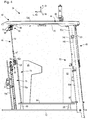
- FIG. 1 an embodiment of a tillage machine according to the invention in the form of a ground or road milling machine is generally designated 10. It comprises a machine frame 12, which forms the basic framework for a machine body 13.
- the machine body 13 comprises the machine frame 12 and components of the machine 10 connected to the machine frame 12, possibly relative to said machine frame 12.
- the machine body 13 includes front lifting columns 14 and rear lifting columns 16 which are connected at one end to the machine frame 12 and at the other end to front drives 18 and rear drives 20, respectively.
- the distance of the machine frame 12 from the drives 18 and 20 is variable by the lifting columns 14 and 16.
- the drives 18 and 20 are exemplified as catenary drives. Individual or all drives 18 and / or 20 can deviate from this also wheel drives.
- FIG. 1 The viewer of FIG. 1 looks at the tillage machine or "machine" 10 in the direction of the plane of FIG. 1 orthogonal machine transverse direction Q.
- An orthogonal to the cross machine direction Q machine longitudinal direction is denoted by L and extends parallel to the plane of FIG. 1
- a machine height direction H also runs parallel to the plane of the drawing FIG. 1 and orthogonal to the machine longitudinal and cross machine directions L and Q, respectively.
- the arrowhead of the machine longitudinal direction L in FIG. 1 points in the forward direction.
- the Machine height direction H runs parallel to the yaw axis Gi of the machine 10
- the machine longitudinal direction L runs parallel to the roll axis Ro
- the machine transverse direction Q runs parallel to the pitch axis Ni.
- the soil working machine 10 has a control station 24, from which an operator can control the machine 10 via a control panel 26.
- a work assembly 28 is arranged, here by way of example as a milling assembly 28 with a recorded in a Fräswalzenkasten 30 milling drum 32 which is rotatable about a running in the cross-machine direction Q milling axis R, thus during a soil treatment underground material starting from the contact surface AO of the ground U can be removed with a certain through the relative height of the machine frame 12 milling depth.
- the milling drum 32 is therefore a working device in the sense of the present application. Alternatively or additionally, the milling drum 32 can be accommodated relative to the machine frame 12 height-adjustable on this.
- the height adjustment of the machine frame 12 by the lifting columns 14 and 16 also serves to adjust the milling or general working depth of the machine 10 during tillage.
- the tillage machine 10 shown by way of example is a large milling machine, for which the arrangement of the milling assembly 28 in the machine longitudinal direction L between the front and rear drives 18 and 20 is typical.
- Such large milling machines or soil removing machines in general may include a conveyor belt for transporting removed soil material away from the machine 10. An even in the machine 10 basically present conveyor belt is for reasons of clarity in FIG. 1 not shown.
- the machine 10 has two lifting columns 14 and 16, each with a drive 18 and 20 connected thereto, both in its front end area and in its rear end area.
- the front lifting columns 14 are in a manner known per se, respectively by means of a drive connection structure 34, such as a drive fork 18 in the cross-machine direction Q cross-connecting fork, coupled to the drives 18.
- the rear lift columns 16 are connected to their respective drive 20 via a drive interconnect structure 36 constructed identically to the drive interconnect structure 34.
- the drives 18 and 20 are constructed substantially identical and form the chassis 22 of the machine.
- the drives 18 and 20 are driven by a motor, usually by a hydraulic motor, not shown.
- the drive power source of the machine 10 forms a recorded on the machine frame 12 internal combustion engine 39. Through them, the milling drum 32 is driven in the illustrated embodiment for rotation.
- a hydraulic pressure reservoir is also provided on the machine 10, by which hydraulic motors and hydraulic actuators are operable on the machine.
- the internal combustion engine 39 is thus also the source of the driving force of the machine 10.
- the drive 18 with a direction indicated by the double arrow D running direction has in the example shown, a radially inner receiving and guiding structure 38, on which a revolving crawler 40 is arranged and guided for circulating movement.
- the lifting column 14 and with it the drive 18 is rotatable about a steering axis S by a steering device, not shown.
- a steering device not shown.
- the lifting column 16 and with it the drive 20 can be rotatable by a steering device about a steering axis parallel to the steering axis S steering axis.
- the control station 24 is covered by a protective roof structure 42, which comprises a protective roof 44, which is connected to the machine frame 12 or machine body 13 via a front disk arrangement 46 and a rear wall arrangement 48.
- the protective roof 44 can be raised and lowered on the machine frame 12 by means of a movement guide 50.
- FIG. 1 is the canopy 44 in its raised Operating position shown in which the machine 10 is ready for a machining operation.
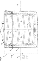
- FIG. 2 shows roughly schematic the control station 24 with its protective roof structure 42 with a view along the roll axis Ro from the front of the machine towards the machine back.
- FIG. 3 shows a side sectional view of the control station 24 with protective roof structure 42 when viewing the section plane III-III of FIG. 2
- FIG. 4 shows a rough schematic uncut view of the control station 24 of FIG. 3 along the pitch axis Ni.
- the disk arrangement 46 extends in the height direction H, ie parallel to the yaw axis Gi, between an upper edge 46a and a lower edge 46b.
- the two edges 46a and 46b are connected by side edges 46c and 46d of the disk assembly 46 to a flat, in particular flat disk assembly 46.
- the side edges 46c and 46d are formed by a transparent disk 52, which carries an upper connecting device 54 and a lower connecting device 56.
- the connectors 54 and 56 are rigidly connected to the disc 52 for co-movement therewith and are therefore part of the disc assembly 46.
- the disc assembly 46 is connected to the canopy 44 by the upper connecting device 54 in an upper connecting portion 58 and is connected to the machine frame 12 via the lower connecting portion 56 in a lower connecting portion 60 via a linear guide 62.
- the linear guide 62 includes two along the pitch axis Ni spaced apart provided parallel guide rails 62a, in which the lower connecting device 56 and thus the lower connecting portion 60 of the disc assembly 46 along the guide rails 62a is movably guided.
- the guide rails 62a are connected in the example shown with the machine frame 12 (see FIGS. 3 to 5 )
- a guide rod 62b is slidably guided on the parallel guide rails 62a.
- rolling body bushing 56a shown only in dashed lines is translationally guided along a lateral movement axis LB defined by the longitudinal axis of the guide rod 62b and rotationally movable about this lateral movement axis LB.
- the Wälz stressese 56 a is rigidly connected to the lower connecting device 56 and thus to the disc 52.
- the upper connecting device 54 may carry other functional devices, such as windscreen wipers 66.
- a spray water container 67 for a non-illustrated cleaning system of the disc 52 is in FIG. 2 also shown.
- the upper connecting device 54 is connected in a manner analogous to the lower connecting device 56 via a parallel to the pitch axis Ni guide rod 68 and a fixedly connected to the upper connecting device 54 WälzSystemse 54a with a shell support 70 of the canopy 44.
- the guide rod 68 is firmly connected to the shell carrier 70.
- the disc assembly 46 is thus translationally movable along a side movement axis SB defined by the longitudinal axis of the guide rod 68 and rotatable about the lateral movement axis SB.
- the driving floor 64 is connected in the illustrated embodiment by vibration damper 65 to the machine frame 12 to the operator on the machine stand 24 of u. a. relieve vibrations induced by the milling operation. The permitted by the vibration decoupling micro-relative movement is negligible in the context of the present application.
- the driving floor 64 is machine frame fixed.
- the disk assembly 46 is displaceable by the described storage by means of Wälz stressesen 54a and 56a and associated guide rods 62b and 68 both relative to the canopy 44 and relative to the Fahrstandêt 64 parallel to the pitch axis Ni.
- the disc assembly 46 has on both side edges 46c and 46d each have a handle formation 47, so that the operator can spend the disc assembly 46 along the pitch axis Ni within their range of motion in a him appear appropriate position.
- the disc assembly 46 may, for example, be moved out of a collision area if, as the machine 10 advances further, during a tillage operation, it is in danger of colliding with an object, such as a traffic light, branches, and the like.
- the tray carrier 70 carries two roof shells 72a and 72b.
- the roof shells 72a and 72b are individually displaceable relative to the shell carrier 70 along a trajectory AB parallel to the pitch axis Ni.
- the roof shells 72a and 72b can also be displaced together relative to the tray carrier 70 along the trajectory AB. Another relative mobility between the roof shells 72a and 72b on the one hand and the tray carrier 70 on the other hand does not exist.
- the tray carrier 70 is through the motion guide 50 along the path HB (see FIG. 3 ) between in the FIGS. 1 to 4 shown raised operating position and the in FIG. 5 shown lowered transport position raised and lowered.
- the preferred telescopically constructed motion guide 50 is based on the sectional drawing of FIG. 3 the movement guide 50 comprises a guide tube 50a which is connected to the machine frame 12 for common movement and therefore is fixed to the machine frame, and a guide tube 50b which is movable relative to this along the movement path HB coinciding with the tube longitudinal axis of the guide tube 50a.
- the guide tubes 50a and 50b are provided in pairs and that offset along the pitch axis Ni to each other. Both guide tube pairs 50a, 50b are preferably constructed identically.
- the movable guide tube 50b forms a Hub Resultssteil and the machine frame fixed guide tube 50a forms a Hubumble outsteil in the sense of the above description introduction.
- a movement actuator in the form of a piston-cylinder arrangement 74 is accommodated, the cylinder 74a of which is articulated on the guide frame 50a fixed to the frame of the machine frame.
- the retractable from the cylinder 74a and retractable into this piston rod 74b is hinged with its free longitudinal end on the movable guide tube 50b.
- the disc assembly 46 By the described type of connection of the disc assembly 46 with the canopy 44, in particular with the shell carrier 70, the disc assembly 46 is displaced along with the protective cover 44 along the movement path HB when the canopy 44 is displaced between its operating position and its transport position. Since the disc assembly 46 is connected in its lower connecting portion 60 via the lower connecting device 56 and the linear guide 62 in the manner described with the control station floor 64, with a shift of the canopy 44 between its operating position and its transport position, the lower edge 46b of the disc assembly 46 at the driver's floor 64 approximated or removed from this, depending on the direction of movement of the canopy 44th
- the disc assembly 46 can thus be lowered into a receiving space 76 in which it is better protected against external vandalism attack than was the case in the prior art.
- the receiving space 76 is covered in the direction of the control station 24 away by the machine body 13, so that the lowered into the receiving space 76 disc assembly 46 would be accessible only if a person would despite the lowered into the transport position shelter 44 in the then reduced control station 24.
- a shield 78 may be provided, which has a shield plate 78a, the disk assembly 46 in the transport position of the canopy to the control station 24 towards substantially parallel and thus so from access the helm 24 protects.
- the shield 78 can have a further shielding plate 78b which is substantially parallel to the shielding plate 78a and delimits the receiving space 76 in the direction away from the control station 24, ie towards the front region of the machine body 13.
- the shield plate 78a projects beyond the disk assembly 46 in its lowered position of FIG. 5 along the pitch axis Ni, preferably in both directions.
- the shielding plate 78a projects beyond the disk arrangement 46 in its lowered position along the yaw axis Gi at least towards the protective roof 44, preferably also in the opposite direction.
- the shielding 78 preferably surrounds the receiving space 76 around the path of movement of the disk arrangement 46 in order to shield the disk arrangement 46 lowered into the receiving space 76 as completely as possible.
- the shielding plate 78a can be directly connected to the operator's floor 64, in particular welded.
- the shielding away from the control station 24 shielding plate 78b may be directly connected to the machine frame 12, in particular welded. Machine frame fixed in this case are both shield plates 78a and 78b.
- the wall assembly 48 For the wall assembly 48, the above applies to the disc assembly 46 what is said, with the proviso that instead of the disc 52, the wall 53 occurs. Also, the wall assembly 48 with a preferably transparent wall 53 is parallel to the pitch axis Ni relative to the canopy 44 and also relative to the operator platform floor 64 via a linear guide displaced on the protective roof structure 42 and the machine frame 12 added. Likewise, by a corresponding rotationally movable connection of the wall assembly 48 with the canopy 44 and with the linear guide not shown in the figures, a transmission of bending moments about a parallel to the pitch axis Ni bending moment axis between canopy 44 and wall assembly 48 and between wall assembly 48 and control station floor 64 prevented.
- the lateral movement axis LB of the disc arrangement 46 and a corresponding lateral movement axis at the lower end region of the wall arrangement 48 preferably run parallel.
- the disc 52 and the wall 53 in both its raised position, when the canopy 44 is in its operating position, as well as in its lowered position when the canopy 44 is in its transport position be aligned parallel to each other.
- the parallel orientation of the wall 53 and disc 52 is given not only in their respective end positions, but also in each intermediate position.
- an equipment cabinet 80 can be provided, in which, for example, tools and / or special operating clothing and / or catering can be accommodated for the machine operator.
- the equipment cabinet 80 may be made robust and serve with sufficient width along the pitch axis Ni as a shield of the lowered wall assembly 48 to the control station 24 out.
- the optional equipment cabinet 80 is in the FIGS. 2 to 5 only drawn in dashed lines.
- each one the control station 24 along the pitch axis Ni limiting side wall 82 roughly illustrated.
- the side walls 82 in FIG. 2 are orthogonal to the drawing plane of FIG. 2 and thus substantially parallel to the yaw axis Gi and parallel to the roll axis Ro.
- Both side walls 82 are displaceable parallel to the pitch axis Ni.
- the example of in FIG. 2 Left side wall 82 is exemplified by the retracted position shown by the solid line and the flared position shown by the dashed line.
- the control station 24 can be widened if necessary, ie be increased along the pitch axis Ni.
- Verstellaktuatoren 84 are provided under the Fahrstandêt, in a preferred form of a piston-cylinder arrangement.
- an electromechanical actuator 84 may also be provided.
- the actuators 84 are independently adjustable, so that the control station 24 can only be widened to one side optionally.
- the operator floor 64 comprises a main operator floor section 64a, which is fixedly connected to the machine frame.
- the operator's platform floor 64 has additional floor components 64b, at each transverse end area of one, which are movably connected to the main operator's floor section 64a, are pivotably connected in the example shown.
- the pivot axis about which the additional floor members 64b are connected to the main floorstand portion 64a is parallel to the roll axis Ro.
- the kinematics of the additional floor components 64b may also be different, may include, for example, a combined rotation and displacement movement.
- Each additional floor component 64b is coupled to its nearest side wall 82 by a coupling part 86 for common movement, preferably mechanically.
- the coupling part 86 ensures that an additional floor component 64b is folded out with the adjustment of its coupled side wall 82 into the deployed position, so that it lies with the main stand floor section 64a in a common plane of extent and thus one Fahrstandêt 64 forms an enlarged area.
- the coupling member 86 ensures that the surface of the driving floor 64 by displacement of the associated additional floor component 64b in the in FIG. 2 position shown with a solid line is reduced again.
- the Verstellaktuatoren 84 and the additional floor components 64b are for reasons of clarity only in FIG. 2 shown.
- FIG. 5 the side wall 82 is shown in dashed outline.
- FIG. 5 shows that when the canopy 44 is lowered into its transport position, the canopy 44, in particular the roof shells 72a and 72b, an upper edge of the side wall 82 in the direction of the control station 24 away over.
- the side wall 82 is in its retracted position.
- FIG. 2 It can be seen that the protective roof 44 extends beyond the pitch axis Ni, the side walls 82 in their retracted positions respectively in the direction of the control station 24 away. Due to the rear grip in the transport position, a vandal attacking the position change of the sunken protective roof 44 is made more difficult.
- a functional component carrier 88 is shown, which in its functional position, as shown in the FIGS. 2 to 4 . 6 and 7 is shown above the canopy 44.
- the functional component carrier 88 carries a functional component 90 at its two end regions in the direction along the pitch axis Ni, in the example shown a laser sensor 90.
- the functional component carrier 88 is articulated about an orthogonal to him extending boom 92 about a pivot axis FS pivotally mounted on the tray carrier 70.
- the functional component carrier 88 is about the boom 92 about the pivot axis FS by 180 ° between its in the Figures 2 . 3 . 4 . 6 and 7 illustrated functional position and its in FIG. 5 shown stowed position adjustable. The adjustment can be done by hand.
- a functional component 90 can protrude from the protective roof 44 along the yaw axis Gi in the direction of the control station 24, when the functional component 90 is in operation during operation of the Machine 10 is required and may be displaced below the upper boundary surface of the canopy 44 when it is not needed or when it bothers, such as during transport or in the event of an imminent collision with objects in the field of use of the machine 10.
- the functional component carrier 88 or / and the arm 92 pass through an opening 94 in the protective roof 44, which is formed in substantially equal parts in each of the roof shells 72a and 72b.
- the functional component carrier 88 in a simple manner mechanically by the roof shells 72a and 72b against unwanted adjustment of its functional position in the Stowed position and vice versa blocked.
- the respective opening halves 94a and 94b are in FIG. 7 to recognize, in which the roof shells 72a and 72b are displaced away from each other along the parallel to the pitch axis Ni Auszugsbahn AB to increase the area covered by the canopy 44 surface.
- the roof shells 72a and 72b are displaced away from each other in opposite directions. However, they can also be displaced together in the same direction relative to the tray carrier 70 to a maneuvering 96 (see FIG. 6 ), in which the operator platform floor 64, in particular in the area of the main operator floor section 64a, is uncovered by the canopy 44, so that an operator in the maneuvering area 96 can then be located on the control station 24 and maneuver the machine 10 when the canopy 44 lowered into its transport position. Because of the in the functional position of the functional component carrier 88 interspersed opening 94, the formation of the maneuvering 96 in the illustrated embodiment, only possible if the functional component carrier 88 has been previously spent in its Stowed position. However, the functional component carrier 88 does not have to be present.
- the Fahrstand founded indicated as Fahrstandêtphase 64 'deviating from the above also along the pitch axis Ni over the canopy 44 in his in FIG. 6 protrude configuration with a small coverage area. Then even a slight displacement of the two roof shells 72a and 72b along their common separation path AB is sufficient to create a sufficient maneuvering 96 '. If the control station floor 64, as described above, does not protrude beyond the protective roof in its transport position along the pitch axis Ni, the maneuvering area 96 can be provided with a correspondingly increased relative mobility of the roof shell 72a or / and 72b relative to the shell carrier 70 with sufficient area.
- the FIG. 6 gives the true proportions only qualitatively-schematically.
- Figures 2 . 4 and 5 show a latch 97 which extends parallel to the floor of the control station 64 at a small distance therefrom.
- the bolt 97 By operating the bolt 97, the canopy 44 can be locked and unlocked in its transport position. The operator can reach the latch 97 standing on the contact surface AO and must not climb to the control station 24 to unlock the canopy 44 in order to spend this in the operating position.
- a recessed channel formation 98 is formed in each case, which serves for the derivation of incident precipitation.
- the outer roof surface of a roof shell 72a and 72b is inclined towards its respective channel formation, so that rainwater striking the roof shells 72a, 72b flows toward the channel formation 98.
- the channel formation 98 the rainwater flows due to a corresponding inclination of the channel bottom along the arrows 99 in FIG. 7 , For clarity, not all arrows 99 are provided with reference numerals.
- An uncovered at roof shells 72a, 72b upwardly exposed portion of the shell carrier 70 is - viewed from above - along the pitch axis Ni concave and along the roll axis Ro inclined at least in its transverse center region. Due to the concavity, precipitate striking the shell support 70 flows to the transverse center. Due to the inclination of the transverse center region, the precipitate flows along the roll axis Ro from the shell support 70, preferably towards the rear longitudinal end of the machine 10. Arrows 99 also roughly indicate the precipitation striking the flow direction on the tray carrier 70.
Abstract
Bodenbearbeitungsmaschine (10), wie etwa Straßenfräse (10), Recycler, Stabilisierer oder Surface-Miner, mit einem Fahrwerk (22) und einem Maschinenrahmen (12), wobei die Bodenbearbeitungsmaschine (10) eine Arbeitsvorrichtung zur Bodenbearbeitung aufweist und wobei am Maschinenrahmen (12) ein Fahrstand (24) mit einem Fahrstandboden (64) und mit wenigstens einer Bedieneinrichtung (26) vorgesehen ist, wobei die Bodenbearbeitungsmaschine (10) ein zwischen einer angehobenen Betriebsstellung und einer abgesenkten Transportstellung relativ zum Fahrstandboden (64) heb- und senkbares Schutzdach (44) aufweist, wobei die Bodenbearbeitungsmaschine (10) eine eine Scheibe (52) umfassende Scheibenanordnung (46) mit einem dem Schutzdach (44) näher gelegenen oberen Rand (46a), mit einem mit Abstand vom oberen Rand (46a) dem Schutzdach (44) ferner gelegenen unteren Rand (46b) und mit zwei den Abstand zwischen dem oberen und dem unteren Rand (46a, 46b) überbrückenden Seitenrändern (46c, 46d) aufweist, wobei die Scheibenanordnung (46) in einem ihrem oberen Rand (46a) näher als ihrem unteren Rand (46b) gelegenen oberen Verbindungsbereich (58) mit dem Schutzdach (44) und in einem ihrem unteren Rand (46b) näher als ihrem oberen Rand (46a) gelegenen unteren Verbindungsbereich (60) mit dem Maschinenrahmen (12) oder/und mit dem Fahrstandboden (64) als einer Verbindungsbasis verbunden ist, wobei die Scheibenanordnung (46) gemeinsam mit dem Schutzdach (44) heb- und senkbar ist, wobei die Scheibenanordnung (46) mit ihrem unteren Rand (46b) an den Fahrstandboden (64) annäherbar und von diesem entfernbar an der Bodenbearbeitungsmaschine (10) aufgenommen ist.

Description
Die vorliegende Erfindung betrifft eine Bodenbearbeitungsmaschine, wie etwa Straßenfräse, Recycler, Stabilisierer oder Surface-Miner, mit einem Fahrwerk und einem vom Fahrwerk getragenen Maschinenrahmen, wobei die Bodenbearbeitungsmaschine eine Arbeitsvorrichtung zur Bodenbearbeitung aufweist und wobei am Maschinenrahmen ein Fahrstand mit einem Fahrstandboden und mit wenigstens einer Bedieneinrichtung zur Steuerung wenigstens einer Funktionseinrichtung der Bodenbearbeitungsmaschine vorgesehen ist, wobei die Bodenbearbeitungsmaschine ein zwischen einer angehobenen Betriebsstellung und einer abgesenkten Transportstellung relativ zum Fahrstandboden heb- und senkbares Schutzdach aufweist, wobei die Bodenbearbeitungsmaschine eine Scheibe umfassende Scheibenanordnung mit einem dem Schutzdach näher gelegenen oberen Rand, mit einem mit Abstand vom oberen Rand dem Schutzdach ferner gelegenen unteren Rand und mit zwei den Abstand zwischen dem oberen und dem unteren Rand überbrückenden Seitenrändern aufweist, wobei die Scheibenanordnung in einem ihrem oberen Rand näher als ihrem unteren Rand gelegenen oberen Verbindungsbereich mit dem Schutzdach und in einem ihrem unteren Rand näher als ihrem oberen Rand gelegenen unteren Verbindungsbereich mit einer maschinenrahmenfesten oder/und mit einer fahrstandbodenfesten Verbindungsbasis verbunden ist.The present invention relates to a tillage machine, such as a road milling machine, recycler, stabilizer or surface miner, with a chassis and a chassis supported by the chassis, wherein the tillage machine has a working device for tillage and wherein the machine frame, a control station with a Fahrstandboden and at least one Operating device for controlling at least one functional device of the tillage machine is provided, wherein the tillage machine has a raised between a raised operating position and a lowered transport position relative to the operator platform floor and canopy, wherein the tillage machine a disc comprising disc assembly with the protective roof closer upper edge, with a lower edge further from the upper edge of the canopy and having two sides bridging the distance between the upper and lower edges nrändern has, wherein the disc assembly is connected in a near its upper edge closer than its lower edge upper connecting portion with the canopy and in a lower edge closer to its lower edge lower connecting portion with a machine frame fixed and / or with a stud base fixed connection base.
Eine Bodenbearbeitungsmaschine dieser Art, in Gestalt einer Straßen-Großfräse der Anmelderin, ist mit der Bezeichnung "W 200" bekannt. Bei dieser Bodenbearbeitungsmaschine ist das Schutzdach über einen vorderen und einen hinteren Verbindungsrahmen derart mit dem Maschinenrahmen verbunden, dass das Schutzdach mit den Verbindungsrahmen ein Parallelogramm-Viergelenkgetriebe bildet. Sowohl der vordere als auch der hintere Verbindungsrahmen sind jeweils um eine in Maschinenquerrichtung (parallel zur Nickachse) verlaufende Maschinenrahmen-Schwenkachse gelenkig mit dem Maschinenrahmen verbunden als auch um eine hierzu parallele Schutzdach-Schwenkachse gelenkig mit dem Schutzdach verbunden. Damit sowohl die Verbindungsrahmen wie auch das Schutzdach in der Transportstellung möglichst flach auf dem Maschinenrahmen aufliegen bzw. an diesem anliegen, weisen die Maschinenrahmen-Schwenkachse und Schutzdach-Schwenkachse für jeden der im Wesentlichen ebenen Verbindungsrahmen einen gleichen Abstand voneinander auf. Die Höhenerstreckung (parallel zur Gierachse) der Bearbeitungsmaschine kann so stark verringert werden, was für eine Einhaltung von maximalen Transport-Außenmaßen beim Transport der Maschine vorteilhaft ist.A tillage machine of this type, in the form of a street milling machine of the applicant, is known by the name "W 200". In this tillage machine, the canopy is connected to the machine frame via front and rear link frames such that the canopy forms a parallelogram four bar linkage with the link frames. Both the front and the rear connecting frame are each connected to a machine frame pivot axis extending in the cross-machine direction (parallel to the pitch axis) pivotally connected to the machine frame as well as a parallel thereto Canopy pivot axis hinged to the canopy. Thus, both the connection frame as well as the shelter in the transport position as flat as possible rest on the machine frame or rest against this, the machine frame pivot axis and protective roof pivot axis for each of the substantially planar connection frame at an equal distance from each other. The vertical extent (parallel to the yaw axis) of the processing machine can be reduced so much, which is advantageous for compliance with maximum external transport dimensions during transport of the machine.
Das Schutzdach der W 200 führt während einer Verstellung zwischen Transportstellung und Betriebsstellung eine durch die beiden Verbindungsrahmen geführte translatorische Bewegung aus, die längs etwa einer Viertelkreis-Bewegungsbahn verläuft. Das Schutzdach wird daher im Stand der Technik nicht nur zum Fahrstandboden hin abgesenkt oder von diesem angehoben, sondern wird gleichzeitig mit der Annäherung an den oder mit dem Anheben von dem Fahrstandboden längs der Maschinenlängsrichtung (parallel zur Rollachse) bewegt.The protective roof of the W 200 performs during an adjustment between transport position and operating position guided by the two connecting frame translational movement, which runs along approximately a quarter circle movement path. Therefore, in the prior art, the canopy is not only lowered or raised from the operator's floor, but is moved simultaneously with the approaching or lifting of the operator's floor along the machine longitudinal direction (parallel to the roll axis).
Da die Verbindungsrahmen der W 200 jeweils eine Scheibenanordnung tragen, geht mit der Änderung des Abstands des Schutzdaches vom Fahrstandboden eine Änderung des Abstands der Scheibenanordnung vom Fahrstandboden einher. Da die Scheibenanordnung der bekannten W 200 gemeinsam mit dem sie tragenden Verbindungsrahmen um die oben genannte, zur Nickachse parallele Maschinenrahmen-Schwenkachse verschwenkt wird, ändert sich mit dem Abstand des Schutzdaches vom Fahrstandboden im Wesentlichen nur der Abstand jenes Bereichs der Scheibenanordnung vom Fahrstandboden, welcher zwischen der Maschinenrahmen-Schwenkachse und dem Schutzdach gelegen ist. Der unmittelbar an der Maschinenrahmen-Schwenkachse gelegene Bereich der Scheibenanordnung ändert seinen Abstand relativ zum Fahrstandboden nicht bzw. nur in vernachlässigbarer Größe oder ändert ihn sogar in einem jenem des Schutzdachs entgegengesetzten Änderungssinn. Dies ändert jedoch nichts daran, dass sich der Schwerpunkt einer von einem Verbindungsrahmen getragenen Scheibenanordnung während der Verstellung des Schutzdaches der bekannten W 200 zwischen Betriebsstellung und Transportstellung vom Fahrstandboden entfernt bzw. an diesem annähert.Since the connection frames of the W 200 each carry a disc assembly, the change of the distance of the canopy from the operator's floor is accompanied by a change in the distance of the disc assembly from the operator's floor. Since the disc arrangement of the known W 200 is pivoted together with the connecting frame supporting them about the above-mentioned, parallel to the pitch axis machine frame pivot axis, changes with the distance of the canopy from the control station floor essentially only the distance that portion of the disc assembly from the control station floor, which between the machine frame pivot axis and the canopy is located. The region of the disk arrangement located directly on the machine frame pivot axis does not change its distance relative to the operator's floor or only to a negligible extent or even changes it in a direction of change which is opposite to that of the protective roof. However, this does not change the fact that the center of gravity of a disk frame supported by a connecting frame during the adjustment the protective roof of the known W 200 between operating position and transport position away from the operator's floor or approaching this.
Dann, wenn sich das Schutzdach in der Transportstellung befindet, ist die Höhenabmessung der Bodenbearbeitungsmaschine derart verringert, bzw. kann über ein Absenken des Maschinenrahmens durch das Fahrwerk zum Aufstandsuntergrund hin derart verringert werden, dass für einen Transport einzuhaltende maximale Transport-Außenmaße auch tatsächlich eingehalten werden können. Beispielsweise darf in Deutschland ein beladener Transport-Sattelauflieger ohne Sondergenehmigung eine Gesamthöhe von 4,00 m nicht überschreiten.Then, when the canopy is in the transport position, the height dimension of the soil tillage machine is so reduced, or can be reduced by lowering the machine frame through the chassis to the ground surface down so that to be observed for a maximum transport transport dimensions are actually met can. For example, in Germany a loaded transport semi-trailer may not exceed a total height of 4.00 m without special permission.
Immer häufiger treten bei Bodenbearbeitungsmaschinen in Phasen eines unbeobachteten Nichtgebrauchs Probleme mit Vandalismus auf. Unbefugte betreten dabei Baustellengelände und machen sich an den dort abgestellten Maschinen zu schaffen. Dabei versuchen manche auch, in den Fahrstand einer Bodenbearbeitungsmaschine zu gelangen. Diese Personen sind in der Regel nicht von technischer Neugier, sondern von Zerstörungswut getrieben, sodass großes Interesse besteht, den Zugang zum Fahrerstand für Unbefugte zu erschweren und auch leicht zerstörbare Baugruppen, wie etwa transparente Scheiben, möglichst vor einem Angriff durch Vandalen zu schützen.More and more problems with tillage machines in phases of unobserved disuse problems with vandalism. Unauthorized persons enter construction sites and bother with the machines parked there. Some also try to get into the control of a tillage machine. These people are usually driven not by technical curiosity, but by destructiveness, so there is great interest in making access to the driver's station for unauthorized persons and also easily destructible assemblies, such as transparent panes, as possible to protect against attack by vandals.
Grundsätzlich kann mit einem Absenken des Schutzdaches von der Betriebsstellung in die Transportstellung ein Zugang in den Fahrstand erschwert werden. Wegen der geschilderten Kinematik des Schutzdaches liegt bei der bekannten W 200 in der Transportstellung des Schutzdaches eine Scheibenanordnung des Fahrstands offen da und ist somit einer Vandalismusgefahr ausgesetzt.Basically, with a lowering of the canopy from the operating position into the transport position, access to the control station can be made more difficult. Because of the described kinematics of the canopy is in the transport position of the canopy, a disc assembly of the control gear is open in the known W 200 and thus exposed to vandalism.
Es ist daher Aufgabe der vorliegenden Erfindung, die eingangs genannte Bodenbearbeitungsmaschine derart weiterzubilden, dass wesentliche Teile ihres Fahrstands, wie beispielsweise die oben genannte Scheibenanordnung, besser gegen einen Vandalismusangriff geschützt werden können als dies bei den Maschinen des Standes der Technik der Fall ist.It is therefore an object of the present invention, the above-mentioned soil working machine such that essential parts of their control station, such as the above disc assembly, can be better protected against a vandal attack than is the case with the machines of the prior art.
Erfindungsgemäß wird diese Aufgabe gelöst durch eine Bodenbearbeitungsmaschine der eingangs genannten Art, bei welcher die Scheibenanordnung gemeinsam mit dem Schutzdach heb- und senkbar ist, wobei die Scheibenanordnung mit ihrem unteren Rand an den Fahrstandboden annäherbar und von diesem entfernbar an der Bodenbearbeitungsmaschine aufgenommen ist.According to the invention this object is achieved by a tillage machine of the type mentioned, in which the disc assembly can be raised and lowered together with the canopy, the disc assembly is approachable with its lower edge to the control stand floor and removably received on the soil cultivation machine.
Anders als die oben geschilderte Scheibenanordnung der bekannten W 200 wird die Scheibenanordnung der erfindungsgemäßen Bodenbearbeitungsmaschine während einer Verstellung des Schutzdaches zwischen der Betriebsstellung und der Transportstellung nicht ausschließlich rotatorisch bewegt, nämlich um die oben beschriebene Maschinen-Schwenkachse verschwenkt. Die Scheibenanordnung wird wenigstens auch translatorisch bewegt. Jeder Punkt der Scheibenanordnung befindet sich daher dann, wenn sich das Schutzdach in der Transportstellung befindet, näher am Fahrstandboden als dann, wenn sich das Schutzdach in der Betriebsstellung befindet. Die Scheibenanordnung kann bei der Verstellung des Schutzdaches zwischen der Betriebs- und der Transportstellung auch rein translatorisch bewegt werden.Unlike the above-described disc arrangement of the known W 200, the disc arrangement of the tillage machine according to the invention during an adjustment of the canopy between the operating position and the transport position is not exclusively rotationally moved, namely pivoted about the machine pivot axis described above. The disc arrangement is at least moved translationally. Each point of the disc assembly is therefore, when the canopy is in the transport position, closer to the operator's floor than when the canopy is in the operating position. The disc assembly can be moved purely translationally in the adjustment of the canopy between the operating and the transport position.
Dabei soll nicht ausgeschlossen sein, dass der translatorischen Bewegung der Scheibenanordnung eine rotatorische Bewegung überlagert ist, etwa zur Vermeidung von mechanischen Biege- oder Torsionsspannungen in der Scheibenanordnung. Durch die translatorische Bewegung der Scheibenanordnung zum Fahrstandboden hin kann die Scheibenanordnung jedoch teilweise oder sogar vollständig verborgen sein, wenn sich das Schutzdach in der Transportstellung befindet. Somit kann die Scheibenanordnung dann, wenn sich das Schutzdach in der Transportstellung befindet, von außen unzugänglich und somit nicht oder nur mit erheblich vergrößertem Aufwand angegriffen werden.It should not be ruled out that the translational movement of the disk assembly is superimposed on a rotational movement, such as to avoid mechanical bending or torsional stresses in the disk assembly. However, due to the translatory movement of the disk arrangement toward the floor of the control gear, the disk arrangement may be partially or even completely hidden when the protective roof is in the transport position. Thus, the disc assembly, when the canopy is in the transport position, inaccessible from the outside and thus not or only be attacked with significantly increased effort.
Die Scheibenanordnung kann dabei eine transparente Scheibe umfassen oder sein, etwa aus Glas oder aus einem transparenten Kunststoff, wie etwa Polymethylmethacrylat (PMMA). Transparenter Kunststoff weist dabei in der Regel eine geringere Dichte als Glas auf und ist weniger bruchempfindlich, dafür ist Glas in der Regel kratzfester. Die Scheibenanordnung kann jedoch auch blickdicht als scheibenförmige Wand ausgebildet sein, etwa, wenn sie in einem Bereich außerhalb eines Arbeitssichtfelds des Maschinenführers angeordnet ist.In this case, the pane arrangement may comprise or be a transparent pane, for example made of glass or of a transparent plastic, such as polymethyl methacrylate (PMMA). Transparent plastic usually has a lower density than glass and is less susceptible to breakage, but glass is usually scratch-resistant. However, the disc assembly may also be opaque formed as a disc-shaped wall, such as when it is located in a region outside a field of view of the machine operator.
Die Scheibenanordnung kann einen die Scheibe einfassenden Rahmen aufweisen, was im Betrieb auf die transparente Scheibe etwaig einwirkende Biege- oder und Verwindungsbelastungen mindern kann, da zwischen dem Schutzdach und dem Maschinenrahmen auftretende Kräfte oder zu Kräften führende Verformungen vom Scheibenrahmen aufgenommen werden können und nicht oder wenigstens nicht vollständig von der Scheibe aufgenommen werden müssen. Der Begriff "Scheibe" ist dabei als Gestaltangabe zu verstehen und bezeichnet ein flächiges Bauteil, dass sich im Wesentlichen in einer Scheibenfläche, bevorzugt Scheibenebene, erstreckt und dessen Dickenrichtung orthogonal zur Scheibenfläche verläuft. Die Abmessungen der Scheibe längs der Scheibenfläche sind dabei um ein Vielfaches größer als ihre Dickenabmessung.The disk assembly may include a frame enclosing the disk, which may reduce any bending or twisting stresses on the transparent disk when in use, since forces occurring between the guard and the machine frame or deformations resulting in forces may be absorbed by the disk frame and not or at least not completely absorbed by the disc. The term "disk" is to be understood as a designation and refers to a planar component that extends substantially in a disk surface, preferably disk plane, and whose thickness direction is orthogonal to the disk surface. The dimensions of the disk along the disk surface are many times greater than their thickness dimension.
Insbesondere die oben genannten Seitenränder der Scheibenanordnung können durch die Scheibe selbst gebildet sein, was vorteilhaft das Sichtfeld durch die Scheibe vergrößert. Zur Verbindung der Scheibenanordnung mit dem Schutzdach im oberen Verbindungsbereich einerseits und mit der Verbindungsbasis im unteren Verbindungsbereich andererseits wird dagegen in der Regel eine Verbindungsvorrichtung erforderlich sein. Eine solche Verbindungsvorrichtung kann an einem Scheibenrahmen ausgebildet oder mit diesem verbunden sein.In particular, the above-mentioned side edges of the disc assembly may be formed by the disc itself, which advantageously increases the field of view through the disc. On the other hand, in order to connect the pane arrangement to the protective roof in the upper connecting area on the one hand and to the connecting base in the lower connecting area on the other hand, a connecting device will generally be required. Such a connection device may be formed on or connected to a window frame.
Der untere Verbindungsbereich der Scheibenanordnung kann mit einem maschinenrahmenfesten, also im Wesentlichen zur gemeinsamen Bewegung mit dem Maschinenrahmen verbundenen Lagerbauteil verbunden sein oder kann mit einem fahrstandbodenfesten, also zur gemeinsamen Bewegung mit dem Fahrstandboden verbundenen Lagerbauteil verbunden sein. Dann, wenn der Fahrstandboden selbst maschinenrahmenfest ist, ist diese Unterscheidung unnötig, da dann jedes zur gemeinsamen Bewegung mit dem Fahrstandboden verbundene Bauteil auch zur gemeinsamen Bewegung mit dem Maschinenrahmen verbunden ist. Dann jedoch, wenn der Fahrstand insgesamt und mit ihm der Fahrstandboden relativ zum Maschinenrahmen verlagerbar angeordnet ist, wird die Scheibenanordnung in ihrem unteren Verbindungsbereich bevorzugt mit einem zur gemeinsamen Bewegung mit dem Fahrstandboden verbundenen Lagerbauteil verbunden sein, sodass Scheibenanordnung, Schutzdach und Fahrstandboden gemeinsam Teil des Fahrstands sein können und gemeinsam mit dem Fahrstand relativ zum Maschinenrahmen verlagert werden können. Um beide Fälle in der vorliegenden Anmeldung erfassen zu können, ist von der Verbindungsbasis die Rede, die je nach Ausgestaltung der Bodenbearbeitungsmaschine der maschinenrahmenfest oder/und der fahrstandbodenfest sein kann. Da relativ zum Maschinenrahmen verlagerbar angeordnete Fahrstandböden jedoch die Ausnahme bilden, ist der Maschinenrahmen bevorzugt die Verbindungsbasis. Fahrstandböden, die unter Zwischenanordnung einer Vibrationsdämpfung lediglich passiv-mikrobeweglich mit dem Maschinenrahmen verbunden sind, sind maschinenrahmenfeste Fahrstandböden im Sinne der vorliegenden Anmeldung.The lower connecting region of the disk arrangement can be connected to a bearing frame-fixed, ie essentially connected to the machine frame, for joint movement with the bearing frame, or can be connected to a stationary-mounted bearing component, that is to say for joint movement with the operator's floor. Then, when the operator's floor is itself machine frame fixed, this distinction is unnecessary, since then each component connected for common movement with the operator's floor is also connected for common movement with the machine frame. Then, however, when the control gear is arranged in total and with him the Fahrstandboden relative to the machine frame displaceable, the disc assembly is preferably connected in its lower connection region with a connected to the common movement with the Fahrstandboden bearing component, so that disc assembly, canopy and Fahrstandboden can be part of the control station together and can be moved together with the control station relative to the machine frame. In order to be able to record both cases in the present application, there is talk of the connection base which, depending on the design of the soil cultivation machine, may be fixed to the frame of the machine frame and / or the stationary floor. However, since the chassis frame displaceably arranged relative to the machine frame form the exception, the machine frame is preferably the connection base. Fahrstandböden, which are only passive-micro-movably connected to the machine frame with intermediate arrangement of a vibration damping, are machine frame fixed control floors in the sense of the present application.
Die Scheibenanordnung ist sowohl in der Betriebsstellung des Schutzdaches als auch Transportstellung als auch in wenigstens einer Zwischenposition während einer Verstellung des Schutzdaches zwischen Betriebs- und Transportstellung sowohl mit dem Schutzdach als auch mit der Verbindungsbasis verbunden. Bevorzugt ist die Scheibenanordnung dauerhaft, also unabhängig von der vom Schutzdach relativ zum Fahrstandboden eingenommenen Höhenposition mit dem Schutzdach und der Verbindungsbasis verbunden.The disc assembly is connected both in the operating position of the canopy and transport position and in at least one intermediate position during an adjustment of the canopy between operating and transport position with both the canopy and the connection base. Preferably, the disc assembly is permanently connected to the protective roof and the connection base independently of the height position occupied by the protective roof relative to the operator's floor.
Während einer Verstellung des Schutzdaches zwischen der Betriebsstellung und der Transportstellung soll eine möglichst definierte Bewegung der Scheibenanordnung gewährleisten werden können. Dies gilt insbesondere für die Bewegung des unteren Verbindungsbereichs. Gemäß einer bevorzugten Weiterbildung ist daher die Scheibenanordnung in ihrem unteren Verbindungsbereich mit der Verbindungsbasis über eine die Entfernungs- und die Annäherungsbewegung des unteren Verbindungsbereichs relativ zur Verbindungsbasis beim Heben bzw. Senken des Schutzdaches führende Linearführung verbunden.During an adjustment of the canopy between the operating position and the transport position a possible defined movement of the disc assembly should be able to ensure. This is especially true for the movement of the lower connection area. According to a preferred development, therefore, the disk arrangement is connected in its lower connection region with the connection base via a linear guide leading the removal and approach movement of the lower connection region relative to the connection base when the protective roof is raised or lowered.
Dabei ist ein Führungsteil der Linearführung, vorzugsweise eine Führungsschiene, fest mit der Verbindungsbasis verbunden. Dieses Führungsteil bildet das oben genannte maschinenrahmen- oder fahrstandbodenfeste Lagerbauteil. Ein weiteres Führungsteil der Linearführung, vorzugsweise ein am ersten Führungsteil beweglich geführter Führungswagen oder Führungsschlitten oder Gleitstein oder dergleichen, ist mit dem unteren Verbindungsbereich der Scheibenanordnung verbunden. Dabei sind die beiden Führungsteile längs einer von der Linearführung vorgegebenen Führungsbahn relativ zueinander beweglich gekoppelt. Lediglich der Vollständigkeit halber sei darauf hingewiesen, dass in kinematischer Umkehr der oben beschriebenen bevorzugten Ausführungsform auch die Scheibenanordnung fest mit einer Führungsschiene verbunden sein kann. Folglich ist dann der Führungswagen oder Führungsschlitten oder Gleitstein oder dergleichen - je nach Ausgestaltung der Maschine - maschinenrahmenfest oder/und fahrstandbodenfest.In this case, a guide part of the linear guide, preferably a guide rail, fixedly connected to the connection base. This guide part forms the abovementioned machine frame or stationary base-fixed bearing component. A further guide part of the linear guide, preferably a guide carriage or guide slide or sliding block or the like movably guided on the first guide part, is connected to the lower connection region of the disk arrangement. In this case, the two guide parts are coupled along a predetermined by the linear guide track relative to each other movable. For the sake of completeness, it should be pointed out that in a kinematic reversal of the preferred embodiment described above, the disk arrangement can also be firmly connected to a guide rail. Consequently, then the guide carriage or guide carriage or sliding block or the like - depending on the design of the machine - machine frame fixed and / or ground stand firm.
Die Linearführung muss dabei den unteren Verbindungsbereich der Scheibenanordnung nicht notwendigerweise längs einer geradlinigen Führungsbahn führen. Die Führungsbahn kann auch eine oder mehrere gekrümmte Bahnbereiche aufweisen. Allerdings wird die Krümmung der Führungsbahn, wenn sie denn überhaupt vorliegt, vorzugsweise deutlich geringer ausfallen als bei der aus dem Stand der Technik bekannten Viertelkreis-Führungsbahn. Gemäß einer bevorzugten Ausführungsform ist die Führungsbahn jedoch geradlinig, um möglichst einfache Bewegungsverhältnisse am Schutzdach und an der Scheibenanordnung erzielen zu können.The linear guide does not necessarily have to guide the lower connection region of the disc arrangement along a linear guideway. The guideway may also have one or more curved track areas. However, the curvature of the guideway, if it is present at all, preferably turn out to be significantly lower than in the known from the prior art quadrant guideway. According to a preferred embodiment, however, the guideway is rectilinear in order to achieve the simplest possible movement conditions on the canopy and on the disc assembly.
Bevorzugt ist die vom Schutzdach überdeckbare Fläche des Fahrstandbodens - anders als bei der bekannten W 200 - in der Transportstellung nicht kleiner als in der Betriebsstellung. Die Überdeckung ist dabei im Zweifel zu ermitteln durch Projektion des Schutzdachs und des Fahrstandbodens längs der Gierachse der Maschine auf eine zur Gierachse orthogonale Projektionsebene.Preferably, the coverable from the canopy surface of the Fahrstandbodens - unlike the known W 200 - in the transport position not smaller than in the operating position. The overlap is to determine in doubt by projecting the protective roof and the Fahrstandbodens along the yaw axis of the machine to a Yaw axis orthogonal projection plane.
Zur Vereinfachung der Hub- und Senkbewegung des Schutzdachs erfolgt diese bevorzugt längs einer geradlinigen Bewegungsbahn. Diese ist zur Gewährleistung ausreichender Überdeckung des Fahrstandbodens bevorzugt parallel zur Gierachse oder gegenüber derselben um nicht mehr als 10°, vorzugsweise um nicht mehr als 7,5° geneigt. Dann, wenn die Bewegungsbahn relativ zur Gierachse geneigt ist, ist diese bevorzugt um eine zur Nickachse parallele Neigeachse geneigt, besonders bevorzugt in Vorwärtsfahrtrichtung, so dass das Schutzdach in der Betriebsstellung dem vorderen Ende der Bodenbearbeitungsmaschine näher gelegen ist als in der Transportstellung. Zur möglichst einfachen und unbelasteten Bewegung des Schutzdaches gemeinsam mit der Scheibenanordnung zwischen der Betriebsstellung und der Transportstellung sind die Bewegungsbahnen des unteren Verbindungsbereichs der Scheibenanordnung einerseits und des Schutzdaches andererseits bevorzugt parallel oder wenigstens um nicht mehr als 5° relativ zueinander um eine zur Nickachse parallele Inklinationsachse geneigt.To simplify the lifting and lowering movement of the protective roof, this preferably takes place along a linear trajectory. This is to ensure sufficient coverage of the Fahrstandbodens preferably parallel to the yaw axis or with respect to the same by not more than 10 °, preferably inclined by not more than 7.5 °. Then, when the trajectory is inclined relative to the yaw axis, this is preferably inclined about a tilt axis parallel to the pitch axis, particularly preferably in the forward direction, so that the canopy is closer to the front end of the tillage machine in the operating position than in the transport position. For the simplest possible and unloaded movement of the canopy together with the disc assembly between the operating position and the transport position, the trajectories of the lower connecting portion of the disc assembly on the one hand and the canopy on the other hand are preferably parallel or at least inclined by not more than 5 ° relative to each other about a pitch axis parallel to the inclination ,
Alternativ kann die Bahn des Schutzdaches bei seiner Verstellung wenigstens abschnittsweise geringfügig gekrümmt sein. Unabhängig davon, ob die Bewegungsbahn des Schutzdaches gekrümmt oder geneigt ist, ist es bevorzugt, dass die längs der Rollachse verlaufende Komponente der Bewegungsbahn nicht mehr als 25 %, vorzugsweise nicht mehr als 20 %, besonders bevorzugt nicht mehr als 12 %, der längs der Gierachse verlaufenden Komponente beträgt. Dadurch kann sichergestellt werden, dass das Schutzdach sowohl in der Transportstellung als auch in der Betriebsstellung einen Großteil, also mehr als die Hälfte, des Fahrstandbodens überdeckt.Alternatively, the path of the canopy may be slightly curved at least in sections during its adjustment. Regardless of whether the trajectory of the canopy is curved or inclined, it is preferred that the along the roll axis extending component of the trajectory not more than 25%, preferably not more than 20%, more preferably not more than 12%, along the Yaw axis extending component amounts. This can ensure that the canopy, both in the transport position and in the operating position covers a large part, ie more than half, of the operator's floor.
Grundsätzlich kann daran gedacht sein, den oberen Verbindungsbereich der Scheibenanordnung starr mit dem Schutzdach oder/und den unteren Verbindungsbereich der Scheibenanordnung starr mit dem ihr zugeordneten Teil der Linearführung zu verbinden. Im Fahr- oder/und Bodenbearbeitungsbetrieb wirken auf den Maschinenrahmen Kräfte ein, die den Maschinenkörper elastisch verformen können, was wiederum belastend auf die Scheibenanordnung wirken kann. Eine solche unerwünschte Belastung kann gemäß einer Weiterbildung der Erfindung dadurch gemindert werden, dass der obere Verbindungsbereich der Scheibenanordnung mit dem Schutzdach um eine zur Bewegungsbahn der Hub- und Senkbewegung des Schutzdaches orthogonale, vorzugsweise zur Nickachse parallele Seiten-Bewegungsachse relativ zum Schutzdach drehbar verbunden ist. Somit können zwischen dem Schutzdach und der Scheibenanordnung keine Biegemomente um die Seiten-Bewegungsachse übertragen werden.In principle, it can be thought of rigidly connecting the upper connecting region of the disk arrangement with the protective roof and / or the lower connecting region of the disk arrangement with its associated part of the linear guide. In driving or / and soil working operations act on the machine frame forces that can deform the machine body elastic, which in turn can have a burden on the disc assembly. Such an undesirable load can be alleviated according to an embodiment of the invention in that the upper connection region of the disc assembly relative to the protective cover to a movement path of the lifting and lowering movement of the canopy relative, preferably parallel to the pitch axis side movement axis is rotatably connected to the canopy. Thus, no bending moments can be transmitted around the side movement axis between the canopy and the disc assembly.
Zusätzlich oder alternativ kann der untere Verbindungsbereich der Scheibenanordnung mit der Verbindungsbasis um eine zur Seiten-Bewegungsachse parallele Lateral-Bewegungsachse relativ zur Verbindungsbasis drehbar verbunden sein. Dies führt dazu, dass zwischen der Verbindungsbasis und der Scheibenanordnung keine um die Lateral-Bewegungsachse wirkenden Biegemomente übertragbar sind. Zur Klarstellung sei angemerkt, dass dann, wenn der untere Verbindungsbereich um die Lateral-Bewegungsachse relativ zur Verbindungsbasis drehbar mit dieser verbunden ist, die Trajektorie der Lateral-Bewegungsachse die Bewegungsbahn des unteren Verbindungsbereichs anzeigt.Additionally or alternatively, the lower connection portion of the disc assembly may be rotatably connected to the connection base about a lateral movement axis parallel to the side movement axis relative to the connection base. As a result, no bending moments acting about the lateral movement axis can be transmitted between the connection base and the disk arrangement. For clarification, it should be noted that when the lower connection region about the lateral movement axis relative to the connection base is rotatably connected thereto, the trajectory of the lateral movement axis indicates the movement path of the lower connection region.
Weiter kann zusätzlich oder alternativ zu der um die Seiten- oder/und um die Lateral-Bewegungsachse drehbaren Verbindung der Scheibenanordnung mit dem Schutzdach bzw. mit der Verbindungsbasis vorgesehen sein, dass der obere Verbindungsbereich mit dem Schutzdach längs der Seiten-Bewegungsachse relativ zum Schutzdach translatorisch verschiebbar verbunden ist oder/und dass der untere Verbindungsbereich mit der Verbindungsbasis längs der Lateral-Bewegungsachse relativ zur Verbindungsbasis translatorisch verschiebbar verbunden ist. Dadurch kann nicht nur eine Kraftübertragung zwischen Schutzdach und Scheibenanordnung oder/und zwischen Verbindungsbasis und Scheibenanordnung parallel zur Seiten- bzw. Lateral-Bewegungsachse unterbunden werden. Eine Verbindung des oberen Verbindungsbereichs der Scheibenanordnung mit Schutzdach mit translatorischem Bewegungsfreiheitsgrad gestattet dem Maschinenführer, das Schutzdach relativ zur Scheibenanordnung längs der Seiten-Bewegungsachse zu verlagern. Eine Verbindung auch des unteren Verbindungsbereichs mit der Verbindungsbasis mit translatorischem Bewegungsfreiheitsgrad gestattet dem Maschinenführer, die Scheibenanordnung relativ zur Verbindungsbasis sowie relativ zum Schutzdach zu verlagern. Bevorzugt sind der obere und der untere Verbindungsbereich sowohl translatorisch längs der als auch rotatorisch um die Seiten-Bewegungsachse und die Lateral-Bewegungsachse bewegbar mit dem Schutzdach bzw. der Verbindungsbasis verbunden. Dies kann konstruktiv in einfacher Weise durch Verwendung einer Paarung aus Wälzkörperbuchse, insbesondere Kugelbuchse, und Führungsstange zur Verbindung der Scheibenanordnung mit dem Schutzdach und mit der Verbindungsbasis realisiert sein. Die Wälzkörperbuchse ist nicht nur längs der Führungsstange translatorisch verlagerbar, sondern auch um die Führungsstange drehbar. Die Kombination aus Führungsstange und Wälzkörperbuchse kann Teil der oben genannten Verbindungsvorrichtung sein, welche die Scheibenanordnung mit dem Schutzdach bzw. der Verbindungsbasis verbindet. Dabei ist die eine Komponente aus Führungsstange und Wälzkörperbuchse mit der Scheibenanordnung und die jeweils andere Komponente mit dem Schutzdach bzw. mit der Verbindungsbasis verbunden.Furthermore, in addition or as an alternative to the connection of the pane arrangement with the protective roof or the connection base which can be rotated around the lateral and / or lateral movement axes, the upper connection region with the protective roof can be translated along the lateral movement axis relative to the protective roof slidably connected and / or that the lower connecting portion is translationally connected to the connecting base along the lateral movement axis relative to the connecting base. As a result, not only a force transmission between the protective roof and the disc arrangement and / or between the connection base and the disc arrangement parallel to the lateral or lateral movement axis can be prevented. Connecting the upper connection portion of the translucent clearance translucent disc assembly allows the operator to displace the canopy relative to the disc assembly along the lateral movement axis. A connection also of the lower connection area with the connection base with translational movement degree of freedom allows the machine operator to shift the pane arrangement relative to the connection base as well as relative to the protective roof. Preferably, the upper and lower connecting portions are both translationally connected along and rotatably about the lateral movement axis and the lateral movement axis movable with the protective roof and the connection base. This can be realized structurally in a simple manner by using a pair of Wälzkörperbuchse, in particular ball bushing, and guide rod for connecting the disc assembly with the canopy and with the connection base. The Wälzkörperbuchse is not only translationally displaceable along the guide rod, but also rotatable about the guide rod. The combination of guide rod and Wälzkörperbuchse may be part of the above-mentioned connection device which connects the disc assembly with the protective roof or the connection base. Here, the one component of guide rod and Wälzkörperbuchse with the disc assembly and the other component is connected to the canopy or with the connection base.
Die Scheibenanordnung kann längs des durch die Führungsstange definierten Verfahrwegs in ihrer Relativposition zur Verbindungsbasis oder/und zum Schutzdach festlegbar sein. Hierzu können aktiv betätigbare Festlegemittel, wie etwa wenigstens eine reibschlüssige Klemme oder wenigstens ein formschlüssiges Rastmittel, vorgesehen sein oder es können passive Festlegemittel vorgesehen sein, wie etwa wenigstens eine überwindbare Verrastung.The disk arrangement may be fixable along the travel path defined by the guide rod in its relative position to the connection base and / or to the protective roof. For this purpose, actively operable fixing means, such as at least one frictional clamp or at least one positive locking means may be provided or passive fixing means may be provided, such as at least one catchable latching.
Zur Vermeidung von Schäden durch Kollision der Scheibenanordnung mit weiteren Bauteilen der Bodenbearbeitungsmaschine kann die Bodenbearbeitungsmaschine eine Sensoranordnung mit wenigstens einem Sensor, etwa einem Näherungssensor oder/und einem Tastsensor, aufweisen. Die Sensoranordnung erfasst, ob sich die Scheibenanordnung in einem vorbestimmten Zulässigkeits-Stellungsbereich befindet, von welchem ausgehend für eine Bewegung der Scheibenanordnung relativ zum Fahrstandboden keine Kollision zu befürchten ist. Eine Bewegungssteuerung des Schutzdachs kann dann derart ausgebildet sein, dass eine Verlagerung von der Betriebsstellung in die Transportstellung nur dann zugelassen wird, wenn ein von der Sensoranordnung an eine die Schutzdachbewegung steuernde Steuereinrichtung übertragenes Erfassungssignal anzeigt, dass sich die Scheibenanordnung im vorbestimmten Zulässigkeits-Stellungsbereich befindet.To avoid damage by collision of the disc assembly with other components of the soil tillage machine, the tillage machine may have a sensor arrangement with at least one sensor, such as a proximity sensor and / or a touch sensor. The sensor arrangement detects whether the pane arrangement is located in a predetermined permissible position range, from which point no collision is to be feared for a movement of the pane arrangement relative to the control room floor. A movement control of the protective roof can then be designed such that a shift from the operating position to the transport position is only permitted if one of the sensor assembly to a protective roof movement controlling device transmitted detection signal indicates that the disc assembly is in the predetermined allowance position range.
Für einen möglichst guten Schutz der Scheibenanordnung vor einem Zugriff von außen dann, wenn sich das Schutzdach in der abgesenkten Transportstellung befindet, kann die Bodenbearbeitungsmaschine eine verbindungsbasisfeste Abschirmung aufweisen, welche einen Aufnahmeraum, in dem sich die Scheibenanordnung bei in die Transportstellung abgesenktem Schutzdach befindet, wenigstens zum Fahrstand hin begrenzt. In entgegengesetzter Richtung, also vom Fahrstand weg, befindet sich entweder der Maschinenkörper als Zugangshindernis oder eine Seitenwandung des Fahrstands. Gelingt dem Vandalen jedoch der Zugang in den Fahrstand, ist die Abschirmung des Aufnahmeraums zum Fahrstand hin besonders hilfreich.For the best possible protection of the disc assembly from external access when the canopy is in the lowered transport position, the soil tillage machine may have a connection base fixed shield, which at least a receiving space in which the disc assembly is lowered in the transport position shelter Limited to the helm. In the opposite direction, ie away from the control station, is either the machine body as an access obstacle or a side wall of the control station. However, if the Vandals succeed in gaining access to the control station, shielding the recording room from the driver's seat is particularly helpful.
Die Abschirmung kann durch wenigstens eine ohnehin im Fahrstand vorhandene Baugruppe gebildet sein, wie etwa durch einen Geräteschrank oder ein Bedienpult. Diese Baugruppen können robust ausgeführt sein und einem Vandalismusangriff lange widerstehen. Als Abschirmung kann jedoch eine gesonderte Abschirmplatte vorgesehen sein, etwa aus Metall oder/und, bevorzugt gefülltem, Kunststoff.The shield may be formed by at least one module already present in the control station, such as a device cabinet or a control panel. These assemblies can be robust and long resist a vandal attack. As a shield, however, a separate shielding plate may be provided, such as metal and / or, preferably filled, plastic.
Da die Scheibenanordnung in der Regel eine flächige, insbesondere ebene, Scheibenanordnung ist, welche sich in lokal zwei sowohl zueinander als auch zur Dickenrichtung der Scheibenanordnung orthogonalen Raumrichtungen erstreckt, begrenzt die Abschirmung den Aufnahmeraum bevorzugt wenigstens der Haupterstreckungsfläche der Scheibenanordnung gegenüberliegend. Die Abschirmung überdeckt dabei bevorzugt die gesamte Scheibenfläche und reicht besonders bevorzugt zu allen Seiten der Haupterstreckungsfläche der Scheibenanordnung über die Scheibe, insbesondere über die gesamte Scheibenanordnung hinaus.Since the disk arrangement is generally a flat, in particular flat, disk arrangement, which extends in two spatial directions orthogonal both to one another and to the thickness direction of the disk arrangement, the shield preferably delimits the receiving space preferably at least the main extension face of the disk arrangement. The shield preferably covers the entire disk surface and particularly preferably extends beyond the disk on all sides of the main extension surface of the disk arrangement, in particular over the entire disk arrangement.
Die Abschirmung kann den Aufnahmeraum auch sowohl zum Fahrstand hin als auch vom Fahrstand weg abschirmen, sodass die Scheibenanordnung in der abgesenkten Stellung auch vom Maschinenkörper her geschützt sein kann, etwa gegen sich im Maschinenkörper bewegende Teile oder sich niederschlagende Dämpfe und dergleichen.The shield can also shield the receiving space both toward the driver's seat and away from the driver's seat, so that the disk arrangement in the lowered position can also be protected by the machine body, for example against itself Machine body moving parts or precipitating vapors and the like.
Die Abschirmung kann für einen möglichst umfassenden Schutz der Scheibenanordnung in der abgesenkten Stellung um die Bewegungsbahn geschlossen umlaufend ausgebildet ist.The shield can be closed around the trajectory closed for the broadest possible protection of the disc assembly in the lowered position.
Die Scheibenanordnung ist bevorzugt eine Front- oder Windschutzscheibenanordnung, welche sich an dem in Vorwärtsfahrtrichtung der Bodenbearbeitungsmaschine vorauseilenden Endbereich des Fahrstands befindet. Dies muss jedoch nicht so sein. Die Scheibenanordnung kann auch eine Rückwand sein mit einer, bevorzugt transparenten, Heckscheibe. Weniger bevorzugt kann die Scheibenanordnung auch eine Seitenwand sein, wiederum bevorzugt, aber nicht zwingend, mit einer transparenten Scheibe.The disc assembly is preferably a front or windshield assembly located on the forward end of the treadmill ahead of the treadmill. However, this does not have to be the case. The disk arrangement can also be a rear wall with a, preferably transparent, rear window. Less preferably, the disc assembly may also be a sidewall, again preferably but not necessarily, with a transparent disc.
Die Scheibenanordnung erstreckt sich bevorzugt in Maschinenquerrichtung, also parallel zur Nickachse. Wenngleich die oben genannte Scheibenanordnung die einzige Scheibenanordnung des Fahrstands sein kann, kann zusätzlich zu der Scheibenanordnung mit Abstand von dieser eine weitere ähnliche oder gleichartige Anordnung an der Bodenbearbeitungsmaschine vorgesehen sein. Diese weitere Anordnung ist nachfolgend lediglich zur besseren Unterscheidung von der oben genannten Scheibenanordnung als "Wandungsanordnung" bezeichnet. Dementsprechend kann die Bodenbearbeitungsmaschine gemäß einer bevorzugten Weiterbildung der vorliegenden Erfindung mit Abstand von der Scheibenanordnung eine Wandungsanordnung mit einer flächigen Wandung aufweisen. Die Wandungsanordnung kann einen dem Schutzdach näher gelegenen oberen Rand, einen mit Abstand vom oberen Rand dem Schutzdach ferner gelegenen unteren Rand und kann zwei den Abstand zwischen dem oberen und dem unteren Rand überbrückende Seitenränder aufweisen. Die Wandungsanordnung kann in einem ihrem oberen Rand näher als ihrem unteren Rand gelegenen oberen Verbindungsbereich mit dem Schutzdach und in einem ihrem unteren Rand näher als ihrem oberen Rand gelegenen unteren Verbindungsbereich mit dem Maschinenrahmen oder/und mit dem Fahrstandboden als einer Verbindungsbasis verbunden sein. Die Wandungsanordnung ist gemeinsam mit dem Schutzdach heb- und senkbar und ist hierzu mit ihrem unteren Rand an den Fahrstandboden annäherbar und von diesem entfernbar an der Bodenbearbeitungsmaschine aufgenommen.The disk arrangement preferably extends in the cross-machine direction, ie parallel to the pitch axis. Although the above disc arrangement may be the sole disc assembly of the operator's cab, in addition to the disc assembly there may be a further similar or similar arrangement to the tillage machine apart therefrom. This further arrangement is referred to hereinafter only for better distinction from the above-mentioned disk arrangement as a "wall assembly". Accordingly, the tillage machine according to a preferred embodiment of the present invention at a distance from the disk assembly having a wall assembly with a flat wall. The wall assembly may include a top edge closer to the canopy, a bottom edge further spaced from the top edge of the canopy, and may have two side edges bridging the distance between the top and bottom edges. The wall assembly may be in a near its upper edge closer than its lower edge located upper connection area with the canopy and in a lower edge closer than its upper edge located lower connection area with the machine frame and / or with the Fahrstandboden as be connected to a connection base. The wall assembly can be raised and lowered together with the canopy and is approachable with this with its lower edge to the operator's floor and removed from this removable on the tillage machine.
Die Wandungsanordnung kann eine transparente Wandung oder eine blickdichte Wandung aufweisen. Sie ist bevorzugt eine Heckwandung bzw. bei transparenter Heckwandung eine Heckscheibe, welche sich an dem in Vorwärtsfahrtrichtung nachlaufenden Endbereich des Fahrstands befindet. Sie erstreckt sich bevorzugt wie die Scheibenanordnung längs der Nickachse der Bodenbearbeitungsmaschine. Die Scheibenanordnung und die Wandungsanordnung können in ihrer angehobenen Stellung, wenn sich das Schutzdach in der Betriebsstellung befindet, parallel zueinander verlaufen, können jedoch auch einen Winkel um eine zur Nickachse parallele Achse einschließen. Wenigstens der obere Rand der Scheibenanordnung und der obere Rand der Wandungsanordnung verlaufen jedoch bevorzugt parallel zueinander und zwar besonders bevorzugt parallel zur Nickachse, also in Maschinenquerrichtung. Bevorzugt sind sowohl Scheibenanordnung als auch Wandungsanordnung in ihrer angehobenen Stellung parallel zur Bewegungsbahn des Schutzdaches zwischen der Betriebsstellung und der Transportstellung angeordnet, sodass die Anordnungen mit geringstmöglichen Bewegungsraumbedarf abgesenkt werden können. Weiter bevorzugt sind die Scheibenanordnung und die Wandungsanordnung auch in ihrer abgesenkten Stellung zueinander parallel, also dann, wenn sich das Schutzdach in seiner Transportstellung befindet. Sofern keine Parallelität von Scheiben- und Wandungsanordnung erforderlich oder gewünscht ist, kann durch die oben beschriebene Konfiguration erreicht werden, dass Scheiben- und Wandungsanordnung in ihrer angehobenen und in ihrer abgesenkten Stellung jeweils die gleiche Relativanordnung zueinander aufweisen, etwa im gleichen Winkel zueinander geneigt sind.The wall arrangement may have a transparent wall or an opaque wall. It is preferably a rear wall or, in the case of a transparent rear wall, a rear window, which is located on the trailing end region of the control station in the forward direction of travel. It preferably extends like the disk arrangement along the pitch axis of the soil working machine. The disc assembly and the wall assembly may be parallel to each other in their raised position when the canopy is in the operative position, but may also include an angle about an axis parallel to the pitch axis. However, at least the upper edge of the disk arrangement and the upper edge of the wall arrangement preferably run parallel to one another, and particularly preferably parallel to the pitch axis, ie in the cross-machine direction. Both disc arrangement and wall arrangement are preferably arranged in its raised position parallel to the path of movement of the canopy between the operating position and the transport position, so that the arrangements can be lowered with the least possible space for movement. More preferably, the disc assembly and the wall assembly are parallel to each other in its lowered position, that is, when the canopy is in its transport position. If no parallelism of the disk and wall arrangement is required or desired, can be achieved by the configuration described above, that the disk and wall assembly in their raised and in their lowered position each have the same relative arrangement to each other, are inclined at approximately the same angle to each other.
Das oben zur Scheibenanordnung sowie zur Scheibe Gesagte gilt mutatis mutandis in gleicher Weise für die Wandungsanordnung bzw. deren Wandung, wobei die Scheibe der Scheibenanordnung durch die Wandung der Wandungsanordnung zu ersetzen ist. Sofern sowohl die Scheibenanordnung wie auch die Wandungsanordnung um oder/und längs von Seiten- bzw. Lateral-Bewegungsachsen beweglich mit dem Schutzdach und mit einem Führungsteil einer Linearführung verbunden sind, sind die Seiten-Bewegungsachsen und die Lateral-Bewegungsachsen der Scheiben- und der Wandungsanordnung zueinander bevorzugt parallel.What has been said above about the pane arrangement and the pane applies mutatis mutandis in the same way for the wall arrangement or its wall, wherein the pane of the pane arrangement is to be replaced by the wall of the wall arrangement. Provided both the disc assembly as well as the wall assembly around and / or along side and lateral axes of motion are movably connected to the canopy and to a guide member of a linear guide, the lateral axes of movement and the lateral axes of movement of the disc and wall assemblies are preferably parallel to one another.
Das Schutzdach kann einen Schalenträger aufweisen, welcher mit einem Hubführungsteil zur gemeinsamen Hub- und Senkbewegung verbunden ist. Das Hubführungsteil wirkt mit einem verbindungsbasisfesten Hubgegenführungsteil zur Führung der Hub- und Senkbewegung des Schutzdaches zusammen. Die beiden Teile: Hubführungsteil und Hubgegenführungsteil bilden gemeinsam eine Bewegungsführung des Schutzdaches zur Hub- und Senkbewegung. Bevorzugt bilden Hubführungsteil und Hubgegenführungsteil eine raumsparende Teleskop-Bewegungsführung. Ein Teil aus Hubführungsteil und Hubgegenführungsteil, vorzugsweise das Hubführungsteil, ist dann in das jeweils andere Teil, vorzugsweise das Hubgegenführungsteil, einfahrbar und aus diesem ausfahrbar.The protective roof may comprise a shell carrier, which is connected to a Hubführungsteil for common lifting and lowering movement. The Hubführungsteil interacts with a connection base fixed Hubgegenführungsteil to guide the lifting and lowering movement of the canopy. The two parts: Hubführungsteil and Hubgegenführungsteil together form a motion guide of the canopy for lifting and lowering movement. Preferably form Hubführungsteil and Hubgegenführungsteil a space-saving telescope motion guide. A part of Hubführungsteil and Hubgegenführungsteil, preferably the Hubführungsteil is then in the other part, preferably the Hubgegenführungsteil, retractable and extendable from this.
Mit dieser Bewegungsführung kann die oben als bevorzugt genannte geradlinige Bewegungsbahn des Schutzdaches bei seiner Verstellung zwischen der Betriebsstellung und der Transportstellung bei geringem Bauraumbedarf realisiert werden.With this motion guide, the above-mentioned as preferred straight trajectory of the canopy can be realized in its adjustment between the operating position and the transport position with low space requirements.
Grundsätzlich kann daran gedacht sein, den Schalenträger relativ zum Hubführungsteil beweglich an diesem anzuordnen, etwa in einer zur Hub- und Senkbewegungsbahn orthogonalen Richtung. Dadurch kann das Schutzdach als Ganzes parallel zum Fahrstandboden verlagert werden. Aus Gründen einer möglichst hohen Stabilität der Schutzdachkonstruktion ist jedoch der Schalenträger bevorzugt starr mit dem Hubführungsteil verbunden.In principle, it may be thought to arrange the tray carrier movable relative to the Hubführungsteil this, such as in a direction orthogonal to the lifting and lowering path. As a result, the protective roof can be moved as a whole parallel to the Fahrstandboden. For reasons of maximum stability of the protective roof construction, however, the shell carrier is preferably rigidly connected to the Hubführungsteil.
Zur Veränderung, insbesondere zur Vergrößerung der mit dem Schutzdach abdeckbaren Fläche des Fahrstandbodens kann an dem Schalenträger wenigstens eine Dachschale relativ zum Schalenträger beweglich aufgenommen sein. Die wenigstens eine Dachschale ist relativ zum Schalenträger translatorisch längs einer Auszugsbahn beweglich, welche mit der Bewegungsbahn der Hub- und Senkbewegung des Schutzdaches einen Winkel einschließt. Dieser Winkel ist bevorzugt ein rechter Winkel oder ein Winkel in einem Bereich von 80° bis 100°, so dass bereits mit einem geringen Verlagerungsweg der wenigstens einen Dachschale eine erhebliche Veränderung der vom Schutzdach überdeckten Fahrstandbodenfläche erzielbar ist. Bevorzugt verläuft die Auszugsbahn wenigstens in der Betriebsstellung des Schutzdachs parallel zur Fahrstandbodenfläche.To change, in particular to increase the coverable with the canopy surface of the Fahrstandbodens can be accommodated on the shell carrier at least one roof shell movable relative to the shell carrier. The at least one roof shell is movable relative to the tray carrier translatorisch along a trajectory, which with the trajectory of the lifting and lowering movement of Shelter encloses an angle. This angle is preferably a right angle or an angle in a range of 80 ° to 100 °, so that even with a small displacement path of the at least one roof shell, a significant change in the shelter covered by the shelter floor surface can be achieved. Preferably, the trajectory is at least in the operating position of the protective roof parallel to the Fahrstandbodenfläche.
Mit "Transportstellung" ist in der vorliegenden Anmeldung grundsätzlich nur eine Stellung des Schutzdaches bezeichnet, welche hinsichtlich ihres verringerten Höhenabstands vom Fahrstandboden eine Einhaltung von vorgegebenen Transportmaßen gestattet. Die Verwendung des Begriffs "Transportstellung" sagt jedoch zunächst nichts darüber aus, in welcher Relativstellung sich das Schutzdach oder Teile davon längs der Nickachse oder längs der Rollachse bezüglich des Maschinenrahmens verlagert befindet. Das Schutzdach befindet sich daher unabhängig von der Relativstellung der wenigstens einen Dachschale relativ zum Schalenträger in der Transportstellung, wenn es entsprechend zum Fahrstandboden hin abgesenkt ist.With "transport position" basically only one position of the protective roof is designated in the present application, which allows compliance with predetermined transport dimensions in terms of their reduced height distance from the operator's floor. However, the use of the term "transport position" initially says nothing about the relative position in which the protective roof or parts thereof is displaced along the pitch axis or along the roll axis with respect to the machine frame. The protective roof is therefore independent of the relative position of the at least one roof shell relative to the tray carrier in the transport position, when it is lowered according to the driving floor.
Der Fahrstand ist bevorzugt längs der Nickachse von Seitenwandungen begrenzt. Längs der Rollachse grenzt der Fahrstand üblicherweise beiderseits an den Maschinenrahmen an. Zur Erschwerung der Zugänglichkeit des Fahrstands bei in die Transportstellung verstellten Schutzdach kann das Schutzdach in der Transportstellung bevorzugt eine Schutzposition einnehmen, in welcher es mit seinen Seitenrandbereichen auf Randbereichen der Seitenwandungen aufliegt oder/und diese auf ihrer vom Fahrstand wegweisenden Seite hintergreift. Ebenso kann das Schutzdach in der Schutzposition mit seinen vorderen und hinteren Randbereichen an Randbereichen des Maschinenrahmens, welche den Fahrstand längs der Rollachse begrenzen, aufliegen oder/und diese auf ihrer vom Fahrstand wegweisenden Seite hintergreifen. So ist eine nahezu hermetische Abriegelung des durch die Transportstellung des Schutzdaches verkleinerten Fahrstandvolumens möglich.The control station is preferably limited along the pitch axis of side walls. Along the roll axis, the control station usually adjoins the machine frame on both sides. In order to hinder the accessibility of the control station when the protective roof is displaced into the transport position, the protective roof can preferably assume a protective position in the transport position, in which it rests with its side edge areas on edge regions of the side walls and / or engages behind on its side facing away from the control station. Likewise, the protective roof in the protective position with its front and rear edge regions at edge regions of the machine frame, which limit the control station along the roll axis, rest or / and engage behind on their side facing away from the control station side. Thus, a virtually hermetic sealing of the reduced by the transport position of the canopy helm volume is possible.
Gerade für den Transport der Maschine und die damit verbundene Einhaltung vorgegebener maximaler Transportmaße kann es vorteilhaft sein, wenn zwar das Schutzdach in die Transportstellung verbracht ist, dennoch der Fahrstand wenigstens bereichsweise zugänglich und nutzbar ist, um die nahezu verstaubereite Bodenbearbeitungsmaschine vom Fahrstand aus auf ein Transportfahrzeug zu verfahren. Um dies zu ermöglichen, kann vorgesehen sein, dass in der Transportstellung, bei Betrachtung jeweils einer Projektion von Schalenträger und Fahrstandboden längs der Gierachse der Bodenbearbeitungsmaschine auf eine zur Gierachse orthogonale Projektionsebene, in der Projektionsebene die vom projizierten Schalenträger eingenommene Fläche kleiner ist als die vom Fahrstandboden eingenommene Fläche. Dadurch kann der Schalenträger nicht die gesamte Fläche des Fahrstandbodens abdecken. Weiter ist bevorzugt vorgesehen, dass die wenigstens eine Dachschale relativ zum Schalenträger eine Manövrierstellung einnehmen kann, in welcher ein Manövrierbereich des Fahrstandbodens vom Schutzdach unbedeckt ist. Somit kann dann wenn die Dachschale in die Manövrierstellung bewegt ist, der Manövrierbereich des Fahrstands trotz des in die Transportstellung abgesenkten Schutzdaches vom Schutzdach unbedeckt sein, sodass in diesem Bereich ein Maschinenführer wenigstens den Bewegungsantrieb der Maschine bedienen und die Umgebung der Maschine beobachten kann. Bevorzugt ist daher vorgesehen, dass sich in dem in der Manövrierstellung nicht abgedeckten Manövrierbereich des Fahrstands die Bedieneinrichtung oder ein Teil der Bedieneinrichtung befindet, welcher eine Steuerung wenigstens eines Fahrbetriebs der Maschine ermöglicht. Es kann auch daran gedacht sein, die Bedieneinrichtung oder Teile davon im Fahrstand beweglich anzuordnen, sodass die Bedieneinrichtung oder ein Teil derselben erforderlichenfalls in den oben genannten nicht abgedeckten Manövrierbereich verbracht werden kann.Especially for the transport of the machine and the associated compliance with predetermined maximum transport dimensions, it may be advantageous, although the canopy is spent in the transport position, yet the control station is at least partially accessible and usable to move the almost dusty tillage machine from the helm to a transport vehicle. In order to make this possible, it can be provided that, in the transport position, when viewing in each case a projection of shell carrier and driving floor along the yaw axis of the soil cultivation machine to a projection plane orthogonal to the yaw axis, in the projection plane the area occupied by the projected shell carrier is smaller than that of the control station floor occupied area. As a result, the shell carrier can not cover the entire surface of the Fahrstandbodens. Furthermore, it is preferably provided that the at least one roof shell can assume a maneuvering position relative to the shell support, in which a maneuvering area of the support floor is uncovered by the protective roof. Thus, when the roof shell is moved into the maneuvering, the maneuvering of the control station be uncovered despite the lowered into the transport position canopy from the canopy, so that in this area a machine operator can operate at least the movement drive of the machine and observe the environment of the machine. Therefore, it is preferably provided that in the maneuvering area of the control station not covered in the maneuvering position, the operating device or a part of the operating device is located, which allows control of at least one driving operation of the machine. It may also be conceived to arrange the operating device or parts thereof movably in the control station so that the operating device or a part thereof can, if necessary, be brought into the above-mentioned uncovered maneuvering area.
Erkenntnisse aus dem bisherigen Maschinenbetrieb haben gezeigt, dass zum Manövrieren der Maschine bei in die Transportstellung abgesenktem Schutzdach und mit der wenigstens einen Dachschale in der Manövrierstellung ein Querendbereich des Fahrstands, also ein längs der Nickachse ganz außen liegender Bereich, als Manövrierbereich von Vorteil ist. Um zu ermöglichen, dass ein Querendbereich des Fahrstands von dem in die Transportstellung abgesenkten Schutzdach unbedeckt verbleiben kann, kann die vom Fahrstandboden eingenommene Fläche längs der Nickachse der Bodenbearbeitungsmaschine in wenigstens einer Richtung über die vom projizierten Schalenträger eingenommene Fläche hinausreichen. Vorzugsweise weist dann die Auszugsbahn, bei Betrachtung in dem kartesischen Koordinatensystem aus Rollachse, Gierachse und Nickachse, längs der Nickachse eine größte Bahnkomponente auf, sodass sie längs der Nickachse sicher ausreichend verlagerbar ist, um einen nicht abgedeckten Manövrierbereich an einem Querende des Fahrstands bilden zu können oder/und um einen im Betrieb zur Verbesserung des Sichtfelds des Maschinenführers vergrößerten, insbesondere verbreiterten Fahrstand mit dem Schutzdach überdecken zu können.Findings from the previous machine operation have shown that for maneuvering the machine lowered into the transport position shelter and with the at least one roof shell in the maneuvering a Querendbereich the control station, ie a lying along the pitch axis outboard area, as a maneuvering advantage. In order to enable a transverse end region of the control station to remain uncovered from the protective roof lowered into the transport position, the area occupied by the operator floor can travel along the pitch axis of the soil cultivation machine in at least one direction over the extend out from the projected tray carrier occupied area. Preferably, then, the Auszugsbahn, as viewed in the Cartesian coordinate system of roll axis, yaw axis and pitch axis, along the pitch axis, a largest web component, so that it is safely sufficiently displaced along the pitch axis to form an uncovered maneuvering at a transverse end of the control station can and / or in order to be able to cover a control station with the protective roof which has been enlarged during operation to improve the field of vision of the machine operator, in particular widened.
Bevorzugt befindet sich der Schalenträger längs der Nickachse in der Maschinenquermitte, wobei sich besonders bevorzugt die längs der Nickachse zu messende Quermitte des Schalenträgers in der in gleicher Richtung zu messender Maschinenquermitte befindet. Häufig ist vor einer Verladung der Maschine auf ein Transportfahrzeug nicht vorherzusehen, wo aufgrund der jeweils am Verladeort herrschenden Platzverhältnisse ein Manövrierbereich vorteilhafterweise gebildet werden soll. Ein Manövrierbereich kann dann an jedem von beiden Querenden des Fahrstands gebildet werden, wenn die vom Fahrstand eingenommene Fläche längs der Nickachse beiderseits über die vom projizierten Schalenträger eingenommene Fläche hinausreicht, wobei die Auszugsbahn, bei Betrachtung in dem kartesischen Koordinatensystem aus Rollachse, Gierachse und Nickachse, eine größte Bahnkomponente längs der Nickachse aufweist.The tray carrier is preferably located along the pitch axis in the machine center, with the transverse center of the tray carrier to be measured along the pitch axis being particularly preferably located in the machine center center to be measured in the same direction. Often, it is not possible to predict before loading the machine onto a transport vehicle, where a maneuvering area should advantageously be formed on the basis of the prevailing space conditions at the loading location. A maneuvering area can then be formed at each of both transverse ends of the control station, when the area occupied by the control station extends beyond the pitch axis on both sides beyond the area occupied by the projected tray carrier, the trajectory, when viewed in the Cartesian coordinate system of roll axis, yaw axis and pitch axis, has a largest web component along the pitch axis.
Eine möglichst große Veränderung der durch das Schutzdach abdeckbaren Fläche, gewünschtenfalls über den Fahrstandboden hinaus, und eine auf den jeweiligen Betriebsfall möglichst gute Anpassbarkeit der Lage und Größe des Schutzdaches kann dadurch erzielt werden, dass an dem Schalenträger wenigstens zwei Dachschalen unabhängig voneinander oder/und gemeinsam miteinander relativ zum Schalenträger bewegbar vorgesehen sind. Da im Betrieb der Bodenbearbeitungsmaschine das Schutzdach hinsichtlich Größe und Lage in der Regel am häufigsten längs der Nickachse verändert werden muss, um abhängig von Sonneneinstrahlung und Witterungseinflüssen den Maschinenführer am Fahrstand optimal zu schützen und um im Vorschubweg der Bearbeitungsmaschine liegenden Hindernissen, wie beispielsweise Ampeln, Verkehrsschildern Bäumen usw., ausweichen zu können, ohne die Maschine von ihrem vorgesehenen Vorschubweg abbringen zu müssen, sind die wenigstens zwei Dachschalen jeweils bevorzugt längs der Nickachse relativ zum Schalenträger bewegbar. Bevorzugt verläuft deren jeweilige Auszugsbahn parallel zur Nickachse, wie oben bereits ausgesagt ist.The largest possible change in the coverable by the canopy surface, if desired on the Fahrstandboden addition, and the best possible adaptability of the position and size of the canopy can be achieved that at the shell support at least two roof shells independently and / or together are provided with each other movable relative to the tray carrier. Since in operation of the tillage machine, the protective roof in terms of size and location usually has to be changed along the pitch axis usually to protect depending on sunlight and weather conditions optimally the operator on the control station and lying in the feed path of the machine tool obstacles such For example, traffic lights, traffic signs trees, etc., to dodge, without having to divert the machine from its intended feed path, the at least two roof shells are each preferably along the pitch axis relative to the tray carrier movable. Preferably, their respective extension path runs parallel to the pitch axis, as already stated above.
Dann, wenn die jeweiligen Auszugsbahnen der wenigstens zwei Dachschalen nicht parallel oder koaxial zu einander sind, gilt das in der vorliegenden Anmeldung in Bezug auf eine vorteilhafte Ausbildung des Schutzdaches über eine Auszugsbahn Gesagte für die Auszugsbahn wenigstens einer Dachschale.Then, if the respective pullout tracks of the at least two roof shells are not parallel or coaxial to each other, this applies in the present application with respect to an advantageous embodiment of the canopy on a pullout train said for the pullout of at least one roof shell.
Das Schutzdach kann nicht nur zur Abdeckung des Fahrstands im Betrieb und während Phasen des Nicht-Gebrauchs dienen, sondern kann außerdem wiederum Funktionsbauteile der Bodenbearbeitungsmaschine tragen. Hierzu kann in konkreterer Ausgestaltung vorgesehen sein, dass an dem Schalenträger oder an dem Hubführungsteil als einem Lagerungsbauteil ein Funktionsbauteilträger zwischen einer betriebsbereiten Funktionsstellung und einer transportbereiten Verstauungsstellung relativ zum Lagerungsbauteil bewegbar angeordnet ist. Ein solcher Funktionsbauteilträger kann wenigstens ein Funktionsbauteil tragen, welches beispielsweise zur Bestimmung der Position der Maschine bzw. der Arbeitsvorrichtung oder/und zur Bestimmung einer Relativanordnung der Maschine bzw. der Arbeitsvorrichtung, insbesondere einer Fräswalze, relativ zum zu bearbeitenden Boden ausgebildet ist. Beispielsweise kann der Funktionsbauteilträger Lasersensoren zur Nivellierung oder/und Empfänger für ein Globales Navigationssatellitensystem (GNSS), wie z. B. GPS, GLONASS oder Galileo tragen.The canopy can not only serve to cover the control station during operation and during periods of non-use, but may also carry functional components of the soil tillage implement. For this purpose, it may be provided in a more concrete embodiment that is arranged on the tray carrier or on the Hubführungsteil as a storage component, a functional component carrier between an operative functional position and a transportable stowage position movable relative to the storage component. Such a functional component carrier can carry at least one functional component, which is designed, for example, for determining the position of the machine or the working device and / or for determining a relative arrangement of the machine or the working device, in particular a milling drum, relative to the floor to be processed. For example, the functional component carrier for leveling laser sensors and / or receivers for a Global Navigation Satellite System (GNSS), such. GPS, GLONASS or Galileo.
Durch die Verlagerbarkeit des Funktionsbauteilträgers zwischen der Funktionsstellung und der Verstauungsstellung kann ein vom Funktionsbauteilträger getragenes Funktionsbauteil in der Funktionsstellung prominent vom Schutzdach und damit vom höchsten Punkt der Maschine vorstehen, was gerade im bevorzugten Fall der oben genannten Lasersensoren von Vorteil ist, damit diese von einer außerhalb der Maschine stationierten Laserquelle, oder allgemein: Signalquelle, leicht erreichbar sind. Trotzdem kann das Funktionsbauteil in der Verstauungsstellung wenigstens in Maschinenhöhenrichtung nicht über die Silhouette des Maschinenkörpers hinausragen.Due to the displaceability of the functional component carrier between the functional position and the stowage position, a functional component carried by the functional component carrier can protrude prominently from the protective roof and thus from the highest point of the machine, which is advantageous in the preferred case of the abovementioned laser sensors, so that they are from outside the machine stationed laser source, or in general: signal source, are easily accessible. Nevertheless, the functional component in the stowed position can not protrude beyond the silhouette of the machine body at least in the machine height direction.
Bevorzugt ist der Funktionsbauteilträger zwischen der Funktionsstellung und der Verstauungsstellung verschwenkbar, da eine Schwenkbewegung einfach zu führen ist und mit geringem Raumbedarf ausgeführt werden kann. Da die Maschine parallel zur Rollachse in der Regel eine wesentlich größere Abmessung aufweist als parallel zur Nickachse, verläuft die Schwenkachse vorzugsweise parallel zur Nickachse. Dann erfolgt beim Schwenken des Funktionsbauteilträgers eine Verlagerung desselben längs der Rollachse und es kann sichergestellt werden, dass der Funktionsbauteilträger in seiner Verstauungsstellung nicht über den übrigen Maschinenköpers vorsteht und unerwünschterweise abmessungsbestimmend wird.Preferably, the functional component carrier is pivotable between the functional position and the stowed position, since a pivoting movement is easy to perform and can be performed with little space. As the machine generally has a substantially larger dimension parallel to the roll axis than parallel to the pitch axis, the pivot axis preferably runs parallel to the pitch axis. Then, during pivoting of the functional component carrier, a displacement thereof takes place along the roll axis and it can be ensured that the functional component carrier in its stowed position does not protrude beyond the remaining machine body and becomes undesirably dimension-determining.
Der Funktionsbauteilträger ist bevorzugt in der Verstauungsstellung durch das Schutzdach gegen eine unerwünschte Verlagerung in die Funktionsstellung geschützt. Weiter bevorzugt ist der Funktionsbauteilträger auch in der Funktionsstellung gegen eine unerwünschte Verlagerung in die Verstauungsstellung durch das Schutzdach geschützt. Dies kann dadurch erreicht werden, dass der Funktionsbauteilträger nur dann von wenigstens einer seiner Stellungen in die jeweils andere Stellung verlagert werden kann, wenn sich die wenigstens eine Dachschale, vorzugsweise wenn sich zwei Dachschalen in einer vorbestimmten, längs ihrer jeweiligen Auszugsbahn ausgezogenen Stellung befinden. Im bevorzugten Fall eines zwischen seinen Stellungen verschwenkbaren Funktionsbauteilträgers ist dieser daher bevorzugt um eine, vorzugsweise zur Nickachse parallele, Schwenkachse zwischen der Funktionsstellung und der Verstauungsstellung verschwenkbar, parallel zu welcher eine größte von drei zueinander paarweise orthogonalen Verlaufskomponenten der Auszugsbahn verläuft. Wiederum ist dabei die Auszugsbahn in einem kartesischen Koordinatensystem aus Nickachse, Gierachse und Rollachse zu betrachten. Bevorzugt verläuft die Auszugsbahn parallel zur Nickachse.The functional component carrier is preferably protected in the stowage position by the canopy against unwanted displacement in the functional position. More preferably, the functional component carrier is protected in the functional position against unwanted displacement in the Stowed position through the canopy. This can be achieved by allowing the functional component carrier to be displaced from at least one of its positions to the other position only when the at least one roof shell, preferably when two roof shells are in a predetermined position extended along their respective trajectory. In the preferred case of a functional component carrier pivotable between its positions, it is therefore preferably pivotable about a pivot axis, preferably parallel to the pitch axis, between the functional position and the stowage position, parallel to which a largest of three mutually orthogonal gradient components of the trajectory extends. Again, the trajectory is to be considered in a Cartesian coordinate system of pitch axis, yaw axis and roll axis. The trajectory preferably runs parallel to the pitch axis.
Die wenigstens eine Dachschale weist daher zur Realisierung der obigen Schutzfunktion des Funktionsbauteilträgers gegen eine unerwünschte Verlagerung von der Funktionsstellung in die Verstauungsstellung eine Ausnehmung auf, welche der Funktionsbauteilträger in der Funktionsstellung durchsetzt, in der Verstauungsstellung dagegen nicht. Ist mehr als eine Dachschale vorhanden ist die Ausnehmung vorzugsweise durch wenigstens zwei Dachschalen, besonders bevorzugt durch genau zwei Dachschalen gebildet, wenn diese sich in einer vorbestimmten, einander angenäherten Stellung befinden.The at least one roof shell therefore has to realize the above protective function of the functional component carrier against unwanted displacement of the functional position in the stowage position on a recess which passes through the functional component carrier in the functional position, in the stowed position, however, not. If more than one roof shell is present, the recess is preferably formed by at least two roof shells, particularly preferably by exactly two roof shells, when they are in a predetermined, mutually approximated position.
Der Fahrstand kann gemäß einer vorteilhaften Weiterbildung der vorliegenden Erfindung seitlich vergrößert werden, sodass sich auch mehrere Personen dort bequem aufhalten können oder/und sodass sich der Maschinenführer längs der Nickachse über einen weiteren Bereich hinweg bewegen kann und dadurch ein vergrößertes Sichtfeld hat. Hierzu ist konstruktiv bevorzugt vorgesehen, dass wenigstens eine den Fahrstand längs der Nickachse der Bodenbearbeitungsmaschine begrenzende Seitenwandung relativ zum Fahrstandboden wenigstens, bevorzugt nur längs der Nickachse translatorisch verlagerbar ist.The control station can be increased laterally according to an advantageous embodiment of the present invention, so that several people can stay there comfortably and / or so that the operator can move along the pitch axis over a wider range and thereby has an enlarged field of view. For this purpose, it is preferably provided structurally that at least one side wall which delimits the control station along the pitch axis of the soil cultivation machine is translationally displaceable relative to the operator floor at least, preferably only along the pitch axis.
Damit der vergrößerte Fahrstand im vergrößerten Bereich auch begehbar ist, kann am Fahrstandboden wenigstens ein Zusatzbodenbauteil angeordnet sein, welches zur Vergrößerung der Fahrstandbodenfläche relativ zu einem Haupt-Fahrstandbodenabschnitt beweglich ist. So kann die Breite der Maschine dann, wenn eine Vergrößerung des Fahrstands nicht erforderlich ist, gering gehalten werden. Bevorzugt wird das wenigstens eine Zusatzbodenbauteil um eine Schwenkachse verschwenkt. Da die Vergrößerung des Fahrstands längs der Nickachse erfolgen soll, verläuft die Schwenkachse des Zusatzbodenbauteils bevorzugt parallel zur Rollachse. Zur erleichterten Bedienung ist die Bewegung des Zusatzbodenbauteils mit der Bewegung der ihm nächstgelegenen Seitenwandung gekoppelt, sodass gleichzeitig mit der Verlagerung der Seitenwandung zur Vergrößerung des Fahrstands das der Seitenwandung zugeordnete Zusatzbodenbauteil ebenfalls derart verlagert wird, dass es in dem vergrößerten Abschnitt des Fahrstands einen begehbaren Bodenabschnitt bildet. Im Falle einer Verkleinerung des Fahrstands durch Verlagerung der Seitenwandung in entgegengesetzter Richtung wird das Zusatzbodenbauteil durch die bevorzugte Bewegungskopplung mit der Seitenwandung zurück in eine Nichtgebrauchsstellung bewegt.So that the enlarged control station can also be walked on in the enlarged area, at least one additional floor component can be arranged on the control room floor, which is movable relative to a main control room floor section in order to enlarge the control room floor area. Thus, the width of the machine can be kept low, if an increase in the control station is not required. Preferably, the at least one additional base component is pivoted about a pivot axis. Since the enlargement of the control station is to take place along the pitch axis, the pivot axis of the additional floor component preferably runs parallel to the roll axis. For ease of operation, the movement of the additional floor component is coupled with the movement of its nearest side wall, so that simultaneously with the displacement of the side wall to increase the driving height of the side wall associated additional floor component is also displaced so that it forms a walk-in floor section in the enlarged portion of the control station , In the case of a reduction of the control station by shifting the side wall in the opposite direction, the additional floor component is moved by the preferred movement coupling with the side wall back into a non-use position.
Die eingangs genannte Funktionseinrichtung, welche durch die Bedieneinrichtung auf dem Fahrstand steuerbar ist, kann ein Bewegungsantrieb oder/und eine Lenkungsvorrichtung der Maschine sein oder/und kann die bodenbearbeitende Arbeitsvorrichtung sein, etwa eine Fräswalze.The aforementioned functional device, which can be controlled by the operating device on the control station, may be a movement drive and / or a steering device of the machine and / or may be the ground-working device, such as a milling drum.
Die vorliegende Anmeldung betrifft außerdem ein Verfahren zur Veränderung der Höhenabmessung einer Bodenbearbeitungsmaschine, insbesondere einer Bodenbearbeitungsmaschine, wie sie oben beschrieben ist.The present application also relates to a method for changing the height dimension of a tillage machine, in particular a tillage machine, as described above.
Die vorliegende Erfindung wird nachfolgend anhand der beiliegenden Zeichnungen näher erläutert. Es stellt dar:
- Figur 1
- eine grobschematische Seitenansicht einer Bodenbearbeitungsmaschine gemäß einer Ausnutzung der vorliegenden Erfindung,
- Figur 2
- eine grobschematische Vorderansicht des Schutzdachaufbaus der Bodenbearbeitungsmaschine von
Figur 1 , - Figur 3
- eine grobschematische Schnittansicht des Schutzdachaufbaus von
Figur 2 von der Seite, bei Betrachtung der Schnittebene III-III vonFigur 2 , - Figur 4
- eine grobschematische Seitenansicht des Schutzdachaufbaus der
Figuren 2 und3 mit dem Schutzdach in der Betriebsstellung, - Figur 5
- eine grobschematische Seitenansicht des Schutzdachaufbaus von
Figur 4 mit dem Schutzdach in der Transportstellung, - Figur 6
- eine grobschematische Draufsicht auf das Schutzdach des Schutzdachaufbaus der
Figuren 2 bis 5 mit zwei einander maximal angenäherten Dachschalen und - Figur 7
- eine grobschematische Draufsicht auf das Schutzdach von
Figur 6 mit zwei voneinander entfernten Dachschalen und einem zwischen diesen erkennbaren Schalenträger.
- FIG. 1
- 3 is a rough schematic side view of a soil cultivating machine according to an embodiment of the present invention;
- FIG. 2
- a rough schematic front view of the shelter of the tillage machine of
FIG. 1 . - FIG. 3
- a rough schematic sectional view of the shelter of
FIG. 2 from the side, when looking at the cutting plane III-III ofFIG. 2 . - FIG. 4
- a rough schematic side view of the protective roof structure of
Figures 2 and3 with the protective roof in the operating position, - FIG. 5
- a rough schematic side view of the protective roof structure of
FIG. 4 with the protective roof in the transport position, - FIG. 6
- a rough schematic plan view of the canopy of the protective roof structure of
FIGS. 2 to 5 with two maximum approximated roof shells and - FIG. 7
- a rough schematic plan view of the canopy of
FIG. 6 with two separate roof shells and a recognizable between these shell carrier.
In
Der Maschinenkörper 13 umfasst vordere Hubsäulen 14 und hintere Hubsäulen 16, welche einenends mit dem Maschinenrahmen 12 und anderenends mit vorderen Laufwerken 18 bzw. mit hinteren Laufwerken 20 verbunden sind. Der Abstand des Maschinenrahmens 12 von den Laufwerken 18 und 20 ist durch die Hubsäulen 14 und 16 veränderbar.The
Die Laufwerke 18 und 20 sind beispielhaft als Kettenlaufwerke dargestellt. Einzelne oder alle Laufwerke 18 oder/und 20 können abweichend hiervon auch Radlaufwerke sein.The
Der Betrachter von
Die Bodenbearbeitungsmaschine 10 weist einen Fahrstand 24 auf, von dem aus ein Maschinenführer über ein Schaltpult 26 die Maschine 10 steuern kann.The
Unter dem Maschinenrahmen 12 ist eine Arbeitsbaugruppe 28 angeordnet, hier beispielhaft als Fräsbaugruppe 28 mit einer in einem Fräswalzenkasten 30 aufgenommenen Fräswalze 32, die um eine in Maschinenquerrichtung Q verlaufende Fräsachse R rotierbar ist, um damit während einer Bodenbearbeitung Untergrundmaterial ausgehend von der Aufstandsoberfläche AO des Untergrunds U mit einer durch die relative Höhenlage des Maschinenrahmens 12 bestimmten Frästiefe abtragen zu können. Die Fräswalze 32 ist daher eine Arbeitsvorrichtung im Sinne der vorliegenden Anmeldung. Alternativ oder zusätzlich kann die Fräswalze 32 relativ zum Maschinenrahmen 12 höhenverstellbar an diesem aufgenommen sein.Under the
Die Höhenverstellbarkeit des Maschinenrahmens 12 durch die Hubsäulen 14 und 16 dient auch der Einstellung der Fräs- oder allgemein Arbeitstiefe der Maschine 10 bei der Bodenbearbeitung. Es handelt sich bei der beispielhaft dargestellten Bodenbearbeitungsmaschine 10 um eine Großfräse, für die die Anordnung der Fräsbaugruppe 28 in Maschinenlängsrichtung L zwischen den vorderen und den hinteren Laufwerken 18 bzw. 20 typisch ist. Derartige Großfräsen oder auch bodenabtragende Maschinen im Allgemeinen können ein Transportband aufweisen, um abgetragenes Bodenmaterial von der Maschine 10 weg zu transportieren. Ein auch bei der Maschine 10 grundsätzlich vorhandenes Transportband ist aus Gründen besserer Übersichtlichkeit in
In der Seitenansicht von
Die Antriebskraftquelle der Maschine 10 bildet eine am Maschinenrahmen 12 aufgenommene Brennkraftmaschine 39. Durch sie wird die Fräswalze 32 im dargestellten Ausführungsbeispiel zur Drehung angetrieben. Durch die Leistung der Brennkraftmaschine 39 wird außerdem an der Maschine 10 ein Hydraulikdruckreservoir bereitgestellt, durch welches Hydromotoren und hydraulische Aktuatoren an der Maschine betreibbar sind. Die Brennkraftmaschine 39 ist somit auch Quelle der Vortriebskraft der Maschine 10.The drive power source of the
Das Laufwerk 18 mit einer durch den Doppelpfeil D angedeuteten Laufrichtung weist im dargestellten Beispiel eine radial innere Aufnahme-und Führungsstruktur 38 auf, an der eine umlaufbare Laufkette 40 angeordnet und zur Umlaufbewegung geführt ist.The
Die Hubsäule 14 und mit ihr das Laufwerk 18 ist durch eine nicht näher dargestellte Lenkvorrichtung um eine Lenkachse S drehbar. Bevorzugt zusätzlich, aber auch alternativ kann die Hubsäule 16 und mit ihr das Laufwerk 20 durch eine Lenkvorrichtung um eine zur Lenkachse S parallele Lenkachse drehbar sein.The lifting
Der Fahrstand 24 ist von einem Schutzdachaufbau 42 bedeckt, welcher ein Schutzdach 44 umfasst, das über eine vordere Scheibenanordnung 46 und eine hintere Wandungsanordnung 48 mit dem Maschinenrahmen 12 bzw. Maschinenkörper 13 verbunden ist. Wie anhand der nachfolgenden Figuren detailliert erläutert werden wird, ist das Schutzdach 44 mittels einer Bewegungsführung 50 heb- und senkbar am Maschinenrahmen 12 angeordnet. In
Die Scheibenanordnung 46 erstreckt sich in Höhenrichtung H, also parallel zur Gierachse Gi, zwischen einem oberen Rand 46a und einem unteren Rand 46b. Die beiden Ränder 46a und 46b sind durch Seitenränder 46c und 46d der Scheibenanordnung 46 zu einer flächigen, insbesondere ebenen Scheibenanordnung 46 verbunden. Die Seitenränder 46c und 46d sind dabei von einer transparenten Scheibe 52 gebildet, welche eine obere Verbindungsvorrichtung 54 und eine untere Verbindungsvorrichtung 56 trägt. Die Verbindungsvorrichtungen 54 und 56 sind starr mit der Scheibe 52 zur gemeinsamen Bewegung mit dieser verbunden und sind daher Teil der Scheibenanordnung 46.The
Die Scheibenanordnung 46 ist mittels der oberen Verbindungsvorrichtung 54 in einem oberen Verbindungsbereich 58 mit dem Schutzdach 44 verbunden und ist mittels der unteren Verbindungsvorrichtung 56 in einem unteren Verbindungsbereich 60 über eine Linearführung 62 mit dem Maschinenrahmen 12 verbunden.The
Die Linearführung 62 umfasst zwei längs der Nickachse Ni mit Abstand voneinander vorgesehene, parallele Führungsschienen 62a, in welchen die untere Verbindungsvorrichtung 56 und damit der untere Verbindungsbereich 60 der Scheibenanordnung 46 längs der Führungsschienen 62a beweglich geführt ist. Die Führungsschienen 62a sind im dargestellten Beispiel mit dem Maschinenrahmen 12 verbunden (siehe
Genauer ist im dargestellten Ausführungsbeispiel eine Führungsstange 62b an den parallelen Führungsschienen 62a verschieblich geführt. An der Führungsstange 62b ist eine in
Die obere Verbindungsvorrichtung 54 kann weitere Funktionseinrichtungen tragen, wie beispielsweise Scheibenwischer 66. Ein Spritzwasserbehälter 67 für eine nicht näher dargestellte Reinigungsanlage der Scheibe 52 ist in
Wie am besten in der Schnittansicht von
Der Fahrstandboden 64 ist im dargestellten Ausführungsbeispiel durch Vibrationsdämpfer 65 mit dem Maschinenrahmen 12 verbunden, um den Maschinenführer auf dem Maschinenstand 24 von u. a. durch den Fräsbetrieb induzierten Schwingungen zu entlasten. Die durch die Schwingungsentkopplung zugelassene Mikro-Relativbewegung ist im Rahmen der vorliegenden Anmeldung vernachlässigbar. Der Fahrstandboden 64 ist maschinenrahmenfest.The driving
Die Scheibenanordnung 46 ist durch die beschriebene Lagerung mittels Wälzkörperbuchsen 54a und 56a sowie zugeordneten Führungsstangen 62b und 68 sowohl relativ zum Schutzdach 44 als auch relativ zum Fahrstandboden 64 parallel zur Nickachse Ni verschiebbar. Zum Handangriff durch den Maschinenführer weist die Scheibenanordnung 46 an beiden Seitenrändern 46c und 46d jeweils eine Griffformation 47 auf, sodass der Maschinenführer die Scheibenanordnung 46 längs der Nickachse Ni im Rahmen ihres Bewegungsbereichs in eine ihm jeweils geeignet erscheinende Stellung verbringen kann. Somit kann die Scheibenanordnung 46 beispielsweise aus einem Kollisionsbereich bewegt werden, wenn bei fortgesetzter Vorwärtsfahrt der Maschine 10 während eines Bodenbearbeitungsbetriebs eine Kollision mit einem Objekt droht, etwa einer Ampel, Geäst und dergleichen.The
Der Schalenträger 70 trägt zwei Dachschalen 72a und 72b. Die Dachschalen 72a und 72b sind individuell relativ zum Schalenträger 70 längs einer zur Nickachse Ni parallelen Auszugsbahn AB verlagerbar. Die Dachschalen 72a und 72b können auch gemeinsam relativ zum Schalenträger 70 längs der Auszugsbahn AB verlagert werden. Eine weitere Relativbeweglichkeit zwischen den Dachschalen 72a und 72b einerseits und dem Schalenträger 70 andererseits besteht nicht.The
Der Schalenträger 70 ist durch die Bewegungsführung 50 längs der Bewegungsbahn HB (siehe
Die bevorzugt teleskopartig aufgebaute Bewegungsführung 50 wird anhand der Schnittzeichnung von
Im maschinenrahmenfesten Führungsrohr 50a ist ein Bewegungsaktuator in Gestalt einer Kolben-Zylinder-Anordnung 74 aufgenommen, deren Zylinder 74a am maschinenrahmenfesten Führungsrohr 50a angelenkt ist. Die aus dem Zylinder 74a ausfahrbare und in diesen einfahrbare Kolbenstange 74b ist mit ihrem freien Längsende am beweglichen Führungsrohr 50b angelenkt. Durch Betätigung der Kolben-Zylinder-Anordnung 74 kann somit das Schutzdach 44 an den Fahrstandboden 64 angenähert und von diesem entfernt werden.In the
Durch die beschriebene Art der Verbindung der Scheibenanordnung 46 mit dem Schutzdach 44, insbesondere mit dem Schalenträger 70, wird die Scheibenanordnung 46 gemeinsam mit dem Schutzdach 44 längs der Bewegungsbahn HB verlagert, wenn das Schutzdach 44 zwischen seiner Betriebsstellung und seiner Transportstellung verlagert wird. Da die Scheibenanordnung 46 in ihrem unteren Verbindungsbereich 60 über die untere Verbindungsvorrichtung 56 und die Linearführung 62 in der beschriebenen Weise mit dem Fahrstandboden 64 verbunden ist, wird mit einer Verlagerung des Schutzdaches 44 zwischen seiner Betriebsstellung und seiner Transportstellung der untere Rand 46b der Scheibenanordnung 46 an den Fahrstandboden 64 angenähert oder von diesem entfernt, je nach Bewegungsrichtung des Schutzdaches 44.By the described type of connection of the
Die Scheibenanordnung 46 kann so in einen Aufnahmeraum 76 abgesenkt werden, in welchem es gegen einen Vandalismusangriff von außen besser geschützt ist als dies im Stand der Technik der Fall war. Der Aufnahmeraum 76 ist in Richtung vom Fahrstand 24 weg durch den Maschinenkörper 13 abgedeckt, sodass die in den Aufnahmeraum 76 abgesenkte Scheibenanordnung 46 nur dann zugänglich wäre, wenn eine Person trotz des in die Transportstellung abgesenkten Schutzdaches 44 in den dann verkleinerten Fahrstand 24 gelangen würde.The
Um selbst dann einen Angriff auf die Scheibenanordnung 46 verhindern zu können, kann eine Abschirmung 78 vorgesehen sein, welche eine Abschirmplatte 78a aufweist, die der Scheibenanordnung 46 in der Transportstellung des Schutzdaches zum Fahrstand 24 hin im Wesentlichen parallel gegenüberliegt und diese so vor einem Zugriff aus dem Fahrstand 24 schützt. Zusätzlich kann die Abschirmung 78 eine zur Abschirmplatte 78a im Wesentlichen parallele weitere Abschirmplatte 78b aufweisen, welche den Aufnahmeraum 76 in Richtung vom Fahrstand 24 weg, also zum vorderen Bereich des Maschinenkörpers 13 hin begrenzt. Die Abschirmplatte 78a überragt die Scheibenanordnung 46 in deren abgesenkter Stellung von
Für die Wandungsanordnung 48 gilt das oben zur Scheibenanordnung 46 Gesagte entsprechend, mit der Maßgabe, dass an Stelle der Scheibe 52 die Wandung 53 tritt. Auch die Wandungsanordnung 48 mit einer bevorzugt transparenten Wandung 53 ist parallel zur Nickachse Ni relativ zum Schutzdach 44 und ebenso relativ zum Fahrstandboden 64 über eine Linearführung verlagerbar am Schutzdachaufbau 42 bzw. am Maschinenrahmen 12 aufgenommen. Ebenso ist durch eine entsprechende drehbewegliche Verbindung der Wandungsanordnung 48 mit dem Schutzdach 44 und mit der in den Figuren nicht dargestellten Linearführung eine Übertragung von Biegemomenten um eine zur Nickachse Ni parallele Biegemomentenachse zwischen Schutzdach 44 und Wandungsanordnung 48 sowie zwischen Wandungsanordnung 48 und Fahrstandboden 64 verhindert.For the
Die Lateral-Bewegungsachse LB der Scheibenanordnung 46 und einer entsprechenden Lateral-Bewegungsachse am unteren Endbereich der Wandungsanordnung 48 verlaufen bevorzugt parallel. Dadurch können die Scheibe 52 und die Wandung 53 sowohl in ihrer angehobenen Stellung dann, wenn das Schutzdach 44 sich in seiner Betriebsstellung befindet, als auch in ihrer abgesenkten Stellung dann, wenn sich das Schutzdach 44 in seiner Transportstellung befindet, parallel zueinander ausgerichtet sein. Im dargestellten Ausführungsbeispiel ist die parallele Ausrichtung von Wandung 53 und Scheibe 52 nicht nur in ihren jeweiligen Endstellungen, sondern auch in jeder Zwischenstellung gegeben.The lateral movement axis LB of the
An dem dem Maschinenheck näher gelegenen hinteren Bereich des Fahrstands 24 kann ein Geräteschrank 80 vorgesehen sein, in welchem beispielsweise Werkzeug oder/und besondere Betriebskleidung oder/und Verpflegung für den Maschinenführer aufgenommen sein kann. Der Geräteschrank 80 kann robust ausgeführt sein und bei ausreichender Breite längs der Nickachse Ni als Abschirmung der abgesenkten Wandungsanordnung 48 zum Fahrstand 24 hin dienen. Der optional vorhandene Geräteschrank 80 ist in den
In
Beide Seitenwandungen 82 sind parallel zur Nickachse Ni verlagerbar. Am Beispiel der in
Der Fahrstandboden 64 umfasst einen Haupt-Fahrstandbodenabschnitt 64a, welcher ortsfest mit dem Maschinenrahmen verbunden ist. Im Bereich der Seitenwandungen 82 weist der Fahrstandboden 64 Zusatzbodenbauteile 64b auf, an jedem Querendbereich eines, welche beweglich mit dem Haupt-Fahrstandbodenabschnitt 64a verbunden sind, im dargestellten Beispiel schwenkbeweglich verbunden sind. Die Schwenkachse, um welche die Zusatzbodenbauteile 64b mit dem Haupt-Fahrstandbodenabschnitt 64a verbunden sind, verläuft parallel zur Rollachse Ro. Dies ist jedoch nur eine grobschematische Darstellung. Die Kinematik der Zusatzbodenbauteile 64b kann auch abweichend sein, kann beispielsweise eine kombinierte Dreh- und Verschiebebewegung umfassen. Jedes Zusatzbodenbauteil 64b ist mit der ihm nächstgelegenen Seitenwandung 82 durch ein Koppelteil 86 zur gemeinsamen Bewegung, bevorzugt mechanisch, gekoppelt. Das Koppelteil 86 sorgt dafür, dass ein Zusatzbodenbauteil 64b mit der Verstellung seiner gekoppelten Seitenwandung 82 in die ausgestellte Stellung ausgeklappt wird, sodass es mit dem Haupt-Fahrstandbodenabschnitt 64a in einer gemeinsamen Erstreckungsebene liegt und somit einen Fahrstandboden 64 mit vergrößerter Fläche bildet. Bei der Rückverstellung der Seitenwandung 82 in die eingezogene Stellung sorgt das Koppelteil 86 dafür, dass die Fläche des Fahrstandbodens 64 durch Verlagerung des zugeordneten Zusatzbodenbauteils 64b in die in
In
In den
Wie am besten in
So kann ein Funktionsbauteil 90 vom Schutzdach 44 längs der Gierachse Gi in Richtung vom Fahrstand 24 weg aufragen, wenn das Funktionsbauteil 90 im Betrieb der Maschine 10 benötigt wird und kann unter die obere Begrenzungsfläche des Schutzdaches 44 verlagert sein, wenn es nicht benötigt wird oder wenn es stört, etwa beim Transport oder im Falle einer drohenden Kollision mit Objekten im Einsatzgebiet der Maschine 10.Thus, a
Der Funktionsbauteilträger 88 oder/und der Ausleger 92 durchsetzen in der Funktionsstellung des Funktionsbauteilträgers 88 eine Öffnung 94 im Schutzdach 44, welche zu im Wesentlichen gleichen Teilen in jeder der Dachschalen 72a und 72b ausgebildet ist. So kann dann, wenn die Dachschalen 72a und 72b, wie es in
In
Wie in
Nachzutragen ist, dass die
In den Dachschalen 72a, 72b ist jeweils eine vertiefte Rinnenformation 98 ausgeformt, welche der Ableitung von auftreffenden Niederschlägen dient. Die äußere Dachfläche einer Dachschale 72a und 72b ist zu ihrer jeweiligen Rinnenformation hin geneigt, so dass auf die Dachschalen 72a, 72b auftreffendes Regenwasser zu der Rinnenformation 98 hin strömt. In der Rinnenformation 98 strömt das Regenwasser aufgrund entsprechender Neigung des Rinnengrundes längs der Pfeile 99 in
Ein bei auseinandergezogenen Dachschalen 72a, 72b nach oben freiliegender Abschnitt des Schalenträgers 70 ist - bei Betrachtung von oben - längs der Nickachse Ni konkav ausgebildet und längs der Rollachse Ro in wenigstens in seinem Quermittenbereich geneigt. Aufgrund der Konkavität strömt auf den Schalenträger 70 auftreffender Niederschlag zur Quermitte. Aufgrund der Neigung des Quermittenbereichs strömt der Niederschlag längs der Rollachse Ro vom Schalenträger 70 ab, bevorzugt zum hinteren Längsende der Maschine 10 hin. Auch am Schalenträger 70 zeigen Pfeile 99 grob die Strömungsrichtung auftreffenden Niederschlags an.An uncovered at
Claims (15)
dadurch gekennzeichnet, dass die Scheibenanordnung (46) gemeinsam mit dem Schutzdach (44) heb- und senkbar ist, wobei die Scheibenanordnung (46) mit ihrem unteren Rand (46b) an den Fahrstandboden (64) annäherbar und von diesem entfernbar an der Bodenbearbeitungsmaschine (10) aufgenommen ist.A soil tillage implement (10), such as a road tiller (10), recycler, stabilizer or surface miner, comprising a chassis (22) and a machine frame (12) carried by the chassis (22), the tillage machine (10) including a working device (32). for groundworking and wherein on the machine frame (12) a control station (24) with a control station floor (64) and with at least one control device (26) for controlling at least one functional device (32) of the tillage machine (10) is provided, wherein the soil tillage machine (10 ) between a raised operating position and a lowered transport position relative to the operator platform floor (64) can be raised and lowered protective roof (44), the tillage machine (10) a disc (52) comprising disc assembly (46) with a protective roof (44) closer located upper edge (46 a), with a distance from the upper edge (46 a) of the canopy (44) further located lower edge (46 b) and m it has two lateral edges (46c, 46d) bridging the distance between the upper and lower edges (46a, 46b), the disc assembly (46) being in an upper connecting region closer to its upper edge (46a) than its lower edge (46b) (58) is connected to the protective roof (44) and in a lower connecting region (60), which is closer to its lower edge (46b) than its upper edge (46a), to a machine frame-fixed or / and to a driving-floor-fixed connecting base,
characterized in that the disc arrangement (46) together with the protective cover (44) can be raised and lowered, wherein the disc arrangement (46) with its lower edge (46b) approachable to the Fahrstandboden (64) and removable from the tillage machine (46 10) is recorded.
dadurch gekennzeichnet, dass die Scheibenanordnung (46) in ihrem unteren Verbindungsbereich (60) mit der Verbindungsbasis über eine die Entfernungs- und die Annäherungsbewegung des unteren Verbindungsbereichs (60) relativ zur Verbindungsbasis beim Heben bzw. Senken des Schutzdaches führende Linearführung (62) verbunden ist.Soil cultivation machine (10) according to claim 1,
characterized in that the disc assembly (46) is connected in its lower connection region (60) to the connection base via a linear guide (62) guiding the removal and approach movement of the lower connection region (60) relative to the connection base when the canopy is raised or lowered ,
dadurch gekennzeichnet, dass der obere Verbindungsbereich (58) der Scheibenanordnung (46) mit dem Schutzdach (44) um eine zur Bewegungsbahn (HB) der Hub- und Senkbewegung des Schutzdaches (44) orthogonale Seiten-Bewegungsachse (SB) relativ zum Schutzdach (44) drehbar verbunden ist oder/und dass der untere Verbindungsbereich (60) der Scheibenanordnung (46) mit der Verbindungsbasis um eine zur Seiten-Bewegungsachse (SB) parallele Lateral-Bewegungsachse (LB) relativ zur Verbindungsbasis drehbar verbunden ist,
oder/und
dass der obere Verbindungsbereich (58) mit dem Schutzdach (44) längs der Seiten-Bewegungsachse (SB) relativ zum Schutzdach (44) translatorisch verschiebbar verbunden ist und dass der untere Verbindungsbereich (60) mit der Verbindungsbasis längs der Lateral-Bewegungsachse (LB) relativ zur Verbindungsbasis translatorisch verschiebbar verbunden ist.Soil cultivation machine (10) according to claim 2,
characterized in that the upper connecting region (58) of the disc arrangement (46) with the protective roof (44) about a to the movement path (HB) of the lifting and lowering movement of the canopy (44) orthogonal side movement axis (SB) relative to the canopy (44 ) and / or that the lower connecting portion (60) of the disc assembly (46) is rotatably connected to the connecting base about a lateral movement axis (LB) parallel lateral movement axis (LB) relative to the connection base,
or and
in that the upper connecting region (58) is translationally connected to the protective roof (44) along the lateral movement axis (SB) relative to the protective roof (44) and that the lower connecting region (60) is connected to the connecting base along the lateral movement axis (LB) is connected translationally displaceable relative to the connection base.
dadurch gekennzeichnet, dass die Bodenbearbeitungsmaschine (10) eine verbindungsbasisfeste Abschirmung (78) aufweist, welche einen Aufnahmeraum (76), in dem sich die Scheibenanordnung (46) in der abgesenkten Stellung befindet, wenigstens zum Fahrstand (24) hin abschirmt.Soil cultivation machine (10) according to one of the preceding claims,
characterized in that the tillage machine (10) has a connection base fixed shield (78), which shields a receiving space (76) in which the disc assembly (46) is in the lowered position, at least to the control station (24).
dadurch gekennzeichnet, dass die Bodenbearbeitungsmaschine (10) mit Abstand von der Scheibenanordnung (46) eine eine flächige Wandung (53) aufweisende Wandungsanordnung (48) aufweist mit einem dem Schutzdach (44) näher gelegenen oberen Rand, mit einem mit Abstand vom oberen Rand dem Schutzdach (44) ferner gelegenen unteren Rand und mit zwei den Abstand zwischen dem oberen und dem unteren Rand überbrückenden Seitenrändern, wobei die Wandungsanordnung (48) in einem ihrem oberen Rand näher als ihrem unteren Rand gelegenen oberen Verbindungsbereich mit dem Schutzdach (44) und in einem ihrem unteren Rand näher als ihrem oberen Rand gelegenen unteren Verbindungsbereich mit dem Maschinenrahmen (12) oder/und mit dem Fahrstandboden (64) als einer Verbindungsbasis verbunden ist, wobei die Wandungsanordnung (48) gemeinsam mit dem Schutzdach (44) heb- und senkbar ist und hierzu mit ihrem unteren Rand an den Fahrstandboden (64) annäherbar und von diesem entfernbar an der Bodenbearbeitungsmaschine (10) aufgenommen ist.Soil cultivation machine (10) according to one of the preceding claims,
characterized in that the tillage machine (10) at a distance from the disc assembly (46) has a flat wall (53) having wall assembly (48) with a protective roof (44) closer to the upper edge, with a distance from the upper edge of the Canopy (44) further located lower edge and with two the distance between the upper and the lower edge bridging side edges, wherein the wall assembly (48) in a near its upper edge closer than its lower edge upper connecting portion with the canopy (44) and in a lower connecting portion closer to its lower edge than its upper edge is connected to the machine frame (12) or / and to the operator floor (64) as a connecting base, the wall assembly (48) being raisable and lowerable together with the protective roof (44) is and with its lower edge to the Fahrstandboden (64) approachable and removable from this on the Bodenbearbeitungsma machine (10) is recorded.
dadurch gekennzeichnet, dass der obere Rand (46a) der Scheibenanordnung (46) und der obere Rand der Wandungsanordnung (48) parallel zueinander verlaufen, vorzugsweise in Maschinenquerrichtung (Q).Soil cultivation machine (10) according to claim 5,
characterized in that the upper edge (46a) of the disc assembly (46) and the upper edge of the wall assembly (48) are parallel to each other, preferably in the cross-machine direction (Q).
dadurch gekennzeichnet, dass das Schutzdach (44) einen Schalenträger (70) aufweist, welcher mit einem Hubführungsteil (50b) zur gemeinsamen Hub- und Senkbewegung verbunden ist, das mit einem verbindungsbasisfesten Hubgegenführungsteil (50a) zur Führung der Hub- und Senkbewegung des Schutzdaches (44) zusammenwirkt, wobei an dem Schalenträger (70) wenigstens eine Dachschale (72a, 72b) relativ zum Schalenträger (70) beweglich aufgenommen ist.Soil cultivation machine (10) according to one of the preceding claims,
characterized in that the protective roof (44) has a shell carrier (70) which is connected to a Hubführungsteil (50b) for common lifting and lowering movement, with a connection base fixed Hubgegenführungsteil (50a) for guiding the lifting and lowering movement of the canopy ( 44), wherein on the shell support (70) at least one roof shell (72a, 72b) relative to the shell carrier (70) is movably received.
dadurch gekennzeichnet, dass die wenigstens eine Dachschale (72a, 72b) relativ zum Schalenträger (70) translatorisch längs einer Auszugsbahn (AB) beweglich ist, welche mit der Bewegungsbahn (HB) der Hub- und Senkbewegung einen, vorzugsweise rechten, Winkel einschließt.Soil cultivation machine (10) according to claim 7,
characterized in that the at least one roof shell (72a, 72b) relative to the tray carrier (70) translationally along a trajectory (AB) is movable, which includes the movement path (HB) of the lifting and lowering a, preferably right, angle.
dadurch gekennzeichnet, dass die vom Fahrstandboden (64) eingenommene Fläche längs der Nickachse (Ni) der Bodenbearbeitungsmaschine (10) in wenigstens einer Richtung, vorzugsweise in zwei entgegengesetzte Richtungen über die vom projizierten Schalenträger (70) eingenommene Fläche hinausreicht, wobei die Auszugsbahn (AB) eine längs der Nickachse (Ni) verlaufende größte Bahnkomponente aufweist, vorzugsweise längs der Nickachse (Ni) verläuft.Soil cultivation machine (10) according to claim 8,
characterized in that the surface occupied by the undercarriage floor (64) extends along the pitch axis (Ni) of the tillage machine (10) in at least one direction, preferably in two opposite directions beyond the area occupied by the projected tray carrier (70), the trajectory (AB ) has a largest path component running along the pitch axis (Ni), preferably along the pitch axis (Ni).
dadurch gekennzeichnet, dass an dem Schalenträger wenigstens zwei Dachschalen (72a, 72b) unabhängig voneinander oder/und gemeinsam relativ zum Schalenträger (70) bewegbar vorgesehen sind.Soil cultivation machine (10) according to one of claims 7 to 9,
characterized in that on the shell support at least two roof shells (72a, 72b) are provided independently of each other and / or together relative to the shell carrier (70) movable.
dadurch gekennzeichnet, dass an dem Schalenträger (70) oder an dem Hubführungsteil (50b) als einem Lagerungsbauteil ein Funktionsbauteilträger (88) zwischen einer betriebsbereiten Funktionsstellung und einer transportbereiten Verstauungsstellung relativ zum Lagerungsbauteil bewegbar, insbesondere verschwenkbar angeordnet ist.Soil cultivation machine (10) according to one of claims 7 to 10,
characterized in that on the tray carrier (70) or on the Hubführungsteil (50b) as a storage component, a functional component carrier (88) between an operative functional position and a transportable stowed position is arranged relative to the storage component movable, in particular pivotable.
dadurch gekennzeichnet, dass der Funktionsbauteilträger (88) um eine Schwenkachse (FS) zwischen der Funktionsstellung und der Verstauungsstellung verschwenkbar ist, parallel zu welcher eine größte von drei zueinander paarweise orthogonalen Verlaufskomponenten der Auszugsbahn (AB) verläuft, vorzugsweise zu welcher die Auszugsbahn (AB) parallel ist.Soil cultivation machine (10) according to claim 11, including claim 8,
characterized in that the functional component carrier (88) about a pivot axis (FS) between the functional position and the stowed position is pivotable, parallel to which a largest of three mutually pairwise orthogonal course components of the Auszugsbahn (AB) extends, preferably to which the Auszugsbahn (AB) is parallel.
dadurch gekennzeichnet, dass wenigstens eine den Fahrstand (24) längs der Nickachse (Ni) der Bodenbearbeitungsmaschine (10) begrenzende Seitenwandung (82) relativ zum Fahrstandboden (64) längs der Nickachse (Ni) translatorisch verlagerbar ist, sodass der Fahrstand (24) längs der Nickachse (Ni) vergrößerbar ist.Soil cultivation machine (10) according to one of the preceding claims,
characterized in that at least one of the control station (24) along the pitch axis (Ni) of the tillage machine (10) limiting side wall (82) relative to the control station floor (64) along the pitch axis (Ni) is translationally displaceable, so that the control station (24) along the pitch axis (Ni) is enlarged.
dadurch gekennzeichnet, dass am Fahrstandboden (64) wenigstens ein Zusatzbodenbauteil (64b) angeordnet ist, welches zur Vergrößerung der Fahrstandbodenfläche relativ zum Fahrstandboden (64) beweglich ist.Soil cultivation machine (10) according to claim 13,
characterized in that on the driving floor (64) at least one additional floor component (64b) is arranged, which is movable to increase the Fahrstandbodenfläche relative to the Fahrstandboden (64).
dadurch gekennzeichnet, dass der Schritt des Hebens des Schutzdaches (44) ein Heben eines mit der Verbindungsbasis verbundenen Verbindungsbereichs (60) der Scheibenanordnung (46) relativ zum Fahrstandboden (64) umfasst und dass der Schritt des Senkens des Schutzdaches (44) ein Senken des mit der Verbindungsbasis verbundenen Verbindungsbereichs (60) der Scheibenanordnung (46) relativ zum Fahrstandboden (64) umfasst.A method for changing the height dimension of a soil tillage implement (10), such as a road tiller (10), recycler, stabilizer or surface miner, in particular a soil tillage implement (10) according to any one of the preceding claims, wherein the tilling machine (10) comprises a machine frame (12) and a working device (32) for tilling and wherein on the machine frame (12) a control station (24) is provided with a Fahrstandboden (64), the tillage machine (10) between a raised operating position and a lowered transport position relative to the Fahrstandboden (64) raising and lowering canopy (44) having a disc assembly (46) connected to both the canopy and a machine frame fixed and / or truck floor fixed base, the method comprising the step of attaching the canopy (44) relative to the truck floor (64) raise or lower,
characterized in that the step of lifting the canopy (44) comprises lifting a connection region (60) of the disc assembly (46) connected to the connection base relative to the operator floor (64), and wherein the step of lowering the canopy (44) includes lowering the guard connecting portion (60) of the disc assembly (46) connected to the connection base relative to the operator floor (64).
Applications Claiming Priority (1)
| Application Number | Priority Date | Filing Date | Title |
|---|---|---|---|
| DE102017221053.2A DE102017221053A1 (en) | 2017-11-24 | 2017-11-24 | Soil cultivation machine with together with a protective roof raised and lowered disc assembly |
Publications (2)
| Publication Number | Publication Date |
|---|---|
| EP3489416A1 true EP3489416A1 (en) | 2019-05-29 |
| EP3489416B1 EP3489416B1 (en) | 2020-06-10 |
Family
ID=64316348
Family Applications (1)
| Application Number | Title | Priority Date | Filing Date |
|---|---|---|---|
| EP18206168.9A Active EP3489416B1 (en) | 2017-11-24 | 2018-11-14 | Soil working machine with an extendable and retractable arrangement combining front window and protective roof and method of changing the height of this soil working machine |
Country Status (4)
| Country | Link |
|---|---|
| US (1) | US10822041B2 (en) |
| EP (1) | EP3489416B1 (en) |
| CN (2) | CN209260809U (en) |
| DE (1) | DE102017221053A1 (en) |
Cited By (1)
| Publication number | Priority date | Publication date | Assignee | Title |
|---|---|---|---|---|
| EP4265844A1 (en) | 2022-04-22 | 2023-10-25 | Wirtgen GmbH | Self-propelled soil working machine with a roof that can be varied in length direction of the machine |
Families Citing this family (8)
| Publication number | Priority date | Publication date | Assignee | Title |
|---|---|---|---|---|
| US10604088B2 (en) * | 2015-05-22 | 2020-03-31 | Yanmar Co., Ltd. | Tractor |
| DE102017221053A1 (en) * | 2017-11-24 | 2019-05-29 | Wirtgen Gmbh | Soil cultivation machine with together with a protective roof raised and lowered disc assembly |
| DE102018002170A1 (en) * | 2017-12-22 | 2019-06-27 | Bomag Gmbh | Self-propelled floor milling machine, especially road milling machine, stabilizer or recycler |
| JP7403438B2 (en) * | 2020-12-24 | 2023-12-22 | 株式会社クボタ | work vehicle |
| DE102021118663A1 (en) * | 2021-04-06 | 2022-10-06 | Bomag Gmbh | GROUND MILLING MACHINE |
| CN115478712A (en) * | 2021-06-16 | 2022-12-16 | 维特根有限公司 | Protective roof, floor finishing machine and method for changing the position of a protective roof |
| DE102021126709A1 (en) * | 2021-10-14 | 2023-04-20 | Wirtgen Gmbh | construction machine |
| US20240092154A1 (en) | 2022-09-21 | 2024-03-21 | Caterpillar Paving Products Inc. | Canopy system for work machine |
Citations (6)
| Publication number | Priority date | Publication date | Assignee | Title |
|---|---|---|---|---|
| JPS5431607U (en) * | 1977-08-03 | 1979-03-01 | ||
| WO1996024725A1 (en) * | 1995-02-12 | 1996-08-15 | Wirtgen Gmbh | Roadworking machine |
| EP0810324A1 (en) * | 1996-05-31 | 1997-12-03 | Joseph Vögele AG | Roadpaver with protection roof |
| DE202013006878U1 (en) * | 2012-07-31 | 2013-08-13 | Caterpillar Paving Products Inc. | Folding cab roof for a cold milling machine |
| EP2723629A1 (en) * | 2011-06-25 | 2014-04-30 | ABG Allgemeine Baumaschinen-Gesellschaft mbH | Road-building machine |
| DE102016010660A1 (en) * | 2016-04-06 | 2017-10-12 | Bomag Gmbh | Self-propelled machine, in particular construction machine, with adjustable cab and method for adjusting a driver's cab of a self-propelled machine |
Family Cites Families (17)
| Publication number | Priority date | Publication date | Assignee | Title |
|---|---|---|---|---|
| US4022026A (en) * | 1976-06-10 | 1977-05-10 | Ray Childress | Safety shield attachment |
| US4079792A (en) * | 1977-06-15 | 1978-03-21 | Mining Equipment Division, A Division Of Fmc Corporation | Mine roof support for a mobile drilling machine |
| US5765316A (en) * | 1996-09-17 | 1998-06-16 | Kavarsky; Raymond R. | Building module, collapsible for transport and expandable for use |
| US6059351A (en) * | 1997-12-03 | 2000-05-09 | Ehnes; Steve L. | Vehicle canopy apparatus |
| WO2007073771A1 (en) * | 2005-12-29 | 2007-07-05 | Renault Trucks | Suspension unit and industrial vehicle comprising such a unit |
| DE102006017516A1 (en) * | 2006-04-13 | 2007-10-18 | Bomag Gmbh | Construction machine with articulated chassis |
| US7246835B1 (en) * | 2006-05-10 | 2007-07-24 | Lockheed Martin Corporation | Height reduction for tactical truck system |
| DE102008028955B4 (en) | 2008-06-18 | 2010-06-02 | Wirtgen Gmbh | Construction machine, in particular road milling machine, miner, recycler or stabilizer |
| DE102008047583A1 (en) | 2008-09-17 | 2010-04-15 | Bomag Gmbh | Protective roof construction for the driver's cab of a construction machine |
| CN202163504U (en) * | 2011-06-27 | 2012-03-14 | 烟台杰瑞石油装备技术有限公司 | Elevating control cab for special-purpose vehicle |
| DE202011050733U1 (en) | 2011-07-15 | 2012-10-25 | Hans Hermann Bergmann | Mobile work machine with height-adjustable driver protection |
| DE202012005043U1 (en) | 2012-05-22 | 2012-08-06 | Philipp Glöckner | Overhead guard |
| US8978311B1 (en) * | 2012-10-05 | 2015-03-17 | Century Industries, Llc | Mobile stage system |
| US20150367897A1 (en) | 2015-08-28 | 2015-12-24 | Caterpillar Paving Products Inc. | Adjustable cab system for machine |
| EP3412830B1 (en) | 2017-06-09 | 2020-01-29 | Joseph Vögele AG | Construction machine with operator stand and access protection |
| US10245921B2 (en) | 2017-06-12 | 2019-04-02 | GM Global Technology Operations LLC | System and method for controlling coolant flow through a heater core of a vehicle based upon an estimated heater core air out temperature |
| DE102017221053A1 (en) * | 2017-11-24 | 2019-05-29 | Wirtgen Gmbh | Soil cultivation machine with together with a protective roof raised and lowered disc assembly |
-
2017
- 2017-11-24 DE DE102017221053.2A patent/DE102017221053A1/en active Pending
-
2018
- 2018-10-31 CN CN201821786157.1U patent/CN209260809U/en not_active Withdrawn - After Issue
- 2018-10-31 CN CN201811285647.8A patent/CN109837939B/en active Active
- 2018-11-14 EP EP18206168.9A patent/EP3489416B1/en active Active
- 2018-11-14 US US16/190,721 patent/US10822041B2/en active Active
Patent Citations (6)
| Publication number | Priority date | Publication date | Assignee | Title |
|---|---|---|---|---|
| JPS5431607U (en) * | 1977-08-03 | 1979-03-01 | ||
| WO1996024725A1 (en) * | 1995-02-12 | 1996-08-15 | Wirtgen Gmbh | Roadworking machine |
| EP0810324A1 (en) * | 1996-05-31 | 1997-12-03 | Joseph Vögele AG | Roadpaver with protection roof |
| EP2723629A1 (en) * | 2011-06-25 | 2014-04-30 | ABG Allgemeine Baumaschinen-Gesellschaft mbH | Road-building machine |
| DE202013006878U1 (en) * | 2012-07-31 | 2013-08-13 | Caterpillar Paving Products Inc. | Folding cab roof for a cold milling machine |
| DE102016010660A1 (en) * | 2016-04-06 | 2017-10-12 | Bomag Gmbh | Self-propelled machine, in particular construction machine, with adjustable cab and method for adjusting a driver's cab of a self-propelled machine |
Cited By (2)
| Publication number | Priority date | Publication date | Assignee | Title |
|---|---|---|---|---|
| EP4265844A1 (en) | 2022-04-22 | 2023-10-25 | Wirtgen GmbH | Self-propelled soil working machine with a roof that can be varied in length direction of the machine |
| DE102022109729A1 (en) | 2022-04-22 | 2023-10-26 | Wirtgen Gmbh | Self-propelled soil cultivation machine with a roof that can be adjusted in length in the longitudinal direction of the machine |
Also Published As
| Publication number | Publication date |
|---|---|
| DE102017221053A1 (en) | 2019-05-29 |
| US10822041B2 (en) | 2020-11-03 |
| EP3489416B1 (en) | 2020-06-10 |
| CN109837939A (en) | 2019-06-04 |
| CN109837939B (en) | 2021-05-04 |
| CN209260809U (en) | 2019-08-16 |
| US20190161131A1 (en) | 2019-05-30 |
Similar Documents
| Publication | Publication Date | Title |
|---|---|---|
| EP3489416B1 (en) | Soil working machine with an extendable and retractable arrangement combining front window and protective roof and method of changing the height of this soil working machine | |
| EP3078773B1 (en) | Self-propelled construction vehicle | |
| EP2636794B1 (en) | Large-scale self-propelled milling machine for machining road surfaces and method for machining road surfaces | |
| DE19631042C5 (en) | Road construction machines for roadworks | |
| DE102015007562B4 (en) | Self-propelled soil milling machine, especially road milling machine, recycler, stabilizer or surface miner, with integrated maintenance plate | |
| EP2166154B1 (en) | Protective roof structure for the driver stand of a construction machine | |
| EP1845014B1 (en) | Construction machine with articulated chassis | |
| DE202011001292U1 (en) | Tunnel washing vehicle | |
| DE102016010660A1 (en) | Self-propelled machine, in particular construction machine, with adjustable cab and method for adjusting a driver's cab of a self-propelled machine | |
| DE4329614C2 (en) | Entry for rail vehicles | |
| EP3468820A1 (en) | Construction machine, in particular a soil compacting machine, specifically a rubber-wheeled roller, method for operating a construction machine and method for producing a construction machine | |
| DE202011050733U1 (en) | Mobile work machine with height-adjustable driver protection | |
| EP3484770B1 (en) | Transport vehicle | |
| DE102020130653A1 (en) | Mobile work machine with a height-adjustable driver's canopy | |
| EP3416912B1 (en) | High mast system for a mobile high reach machine, a high reach machine and method for a high mast reach system | |
| DE102014010488B4 (en) | Tail rotor tiller with moveable ladder | |
| DE102014014704B4 (en) | Ground milling machine and method for pivoting a driving device of a ground milling machine | |
| DE102011122660B4 (en) | Attachment for forage harvesters with integrated chassis | |
| DE102018113590A1 (en) | working machine | |
| EP3538713B1 (en) | Ground milling machine | |
| EP3524736B1 (en) | Soil working machine with servicing panel providing a storage area | |
| DE202005006541U1 (en) | Grass cutting/mowing machine, for grass cutting at roadside verges, has a jib with lateral movement and linked arms mounted to the vehicle and which can be laid and secured to the rear of the driver's cabin | |
| DE102017117492B4 (en) | Lifting vehicle for transporting people in the airport area | |
| DE102020006837A1 (en) | Self-propelled soil milling machine | |
| EP4265844A1 (en) | Self-propelled soil working machine with a roof that can be varied in length direction of the machine |
Legal Events
| Date | Code | Title | Description |
|---|---|---|---|
| PUAI | Public reference made under article 153(3) epc to a published international application that has entered the european phase |
Free format text: ORIGINAL CODE: 0009012 |
|
| STAA | Information on the status of an ep patent application or granted ep patent |
Free format text: STATUS: THE APPLICATION HAS BEEN PUBLISHED |
|
| AK | Designated contracting states |
Kind code of ref document: A1 Designated state(s): AL AT BE BG CH CY CZ DE DK EE ES FI FR GB GR HR HU IE IS IT LI LT LU LV MC MK MT NL NO PL PT RO RS SE SI SK SM TR |
|
| AX | Request for extension of the european patent |
Extension state: BA ME |
|
| STAA | Information on the status of an ep patent application or granted ep patent |
Free format text: STATUS: REQUEST FOR EXAMINATION WAS MADE |
|
| TPAC | Observations filed by third parties |
Free format text: ORIGINAL CODE: EPIDOSNTIPA |
|
| 17P | Request for examination filed |
Effective date: 20191129 |
|
| RBV | Designated contracting states (corrected) |
Designated state(s): AL AT BE BG CH CY CZ DE DK EE ES FI FR GB GR HR HU IE IS IT LI LT LU LV MC MK MT NL NO PL PT RO RS SE SI SK SM TR |
|
| GRAP | Despatch of communication of intention to grant a patent |
Free format text: ORIGINAL CODE: EPIDOSNIGR1 |
|
| STAA | Information on the status of an ep patent application or granted ep patent |
Free format text: STATUS: GRANT OF PATENT IS INTENDED |
|
| INTG | Intention to grant announced |
Effective date: 20200330 |
|
| GRAS | Grant fee paid |
Free format text: ORIGINAL CODE: EPIDOSNIGR3 |
|
| GRAA | (expected) grant |
Free format text: ORIGINAL CODE: 0009210 |
|
| STAA | Information on the status of an ep patent application or granted ep patent |
Free format text: STATUS: THE PATENT HAS BEEN GRANTED |
|
| AK | Designated contracting states |
Kind code of ref document: B1 Designated state(s): AL AT BE BG CH CY CZ DE DK EE ES FI FR GB GR HR HU IE IS IT LI LT LU LV MC MK MT NL NO PL PT RO RS SE SI SK SM TR |
|
| REG | Reference to a national code |
Ref country code: GB Ref legal event code: FG4D Free format text: NOT ENGLISH |
|
| RIN1 | Information on inventor provided before grant (corrected) |
Inventor name: BARIMANI, CYRUS Inventor name: KOERTGEN, ALEXANDER Inventor name: DRUMM, STEPHAN |
|
| REG | Reference to a national code |
Ref country code: CH Ref legal event code: EP Ref country code: AT Ref legal event code: REF Ref document number: 1279290 Country of ref document: AT Kind code of ref document: T Effective date: 20200615 |
|
| REG | Reference to a national code |
Ref country code: DE Ref legal event code: R096 Ref document number: 502018001641 Country of ref document: DE |
|
| REG | Reference to a national code |
Ref country code: IE Ref legal event code: FG4D Free format text: LANGUAGE OF EP DOCUMENT: GERMAN |
|
| REG | Reference to a national code |
Ref country code: LT Ref legal event code: MG4D |
|
| PG25 | Lapsed in a contracting state [announced via postgrant information from national office to epo] |
Ref country code: SE Free format text: LAPSE BECAUSE OF FAILURE TO SUBMIT A TRANSLATION OF THE DESCRIPTION OR TO PAY THE FEE WITHIN THE PRESCRIBED TIME-LIMIT Effective date: 20200610 Ref country code: GR Free format text: LAPSE BECAUSE OF FAILURE TO SUBMIT A TRANSLATION OF THE DESCRIPTION OR TO PAY THE FEE WITHIN THE PRESCRIBED TIME-LIMIT Effective date: 20200911 Ref country code: FI Free format text: LAPSE BECAUSE OF FAILURE TO SUBMIT A TRANSLATION OF THE DESCRIPTION OR TO PAY THE FEE WITHIN THE PRESCRIBED TIME-LIMIT Effective date: 20200610 Ref country code: NO Free format text: LAPSE BECAUSE OF FAILURE TO SUBMIT A TRANSLATION OF THE DESCRIPTION OR TO PAY THE FEE WITHIN THE PRESCRIBED TIME-LIMIT Effective date: 20200910 Ref country code: LT Free format text: LAPSE BECAUSE OF FAILURE TO SUBMIT A TRANSLATION OF THE DESCRIPTION OR TO PAY THE FEE WITHIN THE PRESCRIBED TIME-LIMIT Effective date: 20200610 |
|
| REG | Reference to a national code |
Ref country code: NL Ref legal event code: MP Effective date: 20200610 |
|
| PG25 | Lapsed in a contracting state [announced via postgrant information from national office to epo] |
Ref country code: RS Free format text: LAPSE BECAUSE OF FAILURE TO SUBMIT A TRANSLATION OF THE DESCRIPTION OR TO PAY THE FEE WITHIN THE PRESCRIBED TIME-LIMIT Effective date: 20200610 Ref country code: BG Free format text: LAPSE BECAUSE OF FAILURE TO SUBMIT A TRANSLATION OF THE DESCRIPTION OR TO PAY THE FEE WITHIN THE PRESCRIBED TIME-LIMIT Effective date: 20200910 Ref country code: HR Free format text: LAPSE BECAUSE OF FAILURE TO SUBMIT A TRANSLATION OF THE DESCRIPTION OR TO PAY THE FEE WITHIN THE PRESCRIBED TIME-LIMIT Effective date: 20200610 Ref country code: LV Free format text: LAPSE BECAUSE OF FAILURE TO SUBMIT A TRANSLATION OF THE DESCRIPTION OR TO PAY THE FEE WITHIN THE PRESCRIBED TIME-LIMIT Effective date: 20200610 |
|
| PG25 | Lapsed in a contracting state [announced via postgrant information from national office to epo] |
Ref country code: AL Free format text: LAPSE BECAUSE OF FAILURE TO SUBMIT A TRANSLATION OF THE DESCRIPTION OR TO PAY THE FEE WITHIN THE PRESCRIBED TIME-LIMIT Effective date: 20200610 Ref country code: NL Free format text: LAPSE BECAUSE OF FAILURE TO SUBMIT A TRANSLATION OF THE DESCRIPTION OR TO PAY THE FEE WITHIN THE PRESCRIBED TIME-LIMIT Effective date: 20200610 |
|
| PG25 | Lapsed in a contracting state [announced via postgrant information from national office to epo] |
Ref country code: RO Free format text: LAPSE BECAUSE OF FAILURE TO SUBMIT A TRANSLATION OF THE DESCRIPTION OR TO PAY THE FEE WITHIN THE PRESCRIBED TIME-LIMIT Effective date: 20200610 Ref country code: EE Free format text: LAPSE BECAUSE OF FAILURE TO SUBMIT A TRANSLATION OF THE DESCRIPTION OR TO PAY THE FEE WITHIN THE PRESCRIBED TIME-LIMIT Effective date: 20200610 Ref country code: SM Free format text: LAPSE BECAUSE OF FAILURE TO SUBMIT A TRANSLATION OF THE DESCRIPTION OR TO PAY THE FEE WITHIN THE PRESCRIBED TIME-LIMIT Effective date: 20200610 Ref country code: PT Free format text: LAPSE BECAUSE OF FAILURE TO SUBMIT A TRANSLATION OF THE DESCRIPTION OR TO PAY THE FEE WITHIN THE PRESCRIBED TIME-LIMIT Effective date: 20201012 Ref country code: ES Free format text: LAPSE BECAUSE OF FAILURE TO SUBMIT A TRANSLATION OF THE DESCRIPTION OR TO PAY THE FEE WITHIN THE PRESCRIBED TIME-LIMIT Effective date: 20200610 Ref country code: CZ Free format text: LAPSE BECAUSE OF FAILURE TO SUBMIT A TRANSLATION OF THE DESCRIPTION OR TO PAY THE FEE WITHIN THE PRESCRIBED TIME-LIMIT Effective date: 20200610 |
|
| PG25 | Lapsed in a contracting state [announced via postgrant information from national office to epo] |
Ref country code: PL Free format text: LAPSE BECAUSE OF FAILURE TO SUBMIT A TRANSLATION OF THE DESCRIPTION OR TO PAY THE FEE WITHIN THE PRESCRIBED TIME-LIMIT Effective date: 20200610 Ref country code: SK Free format text: LAPSE BECAUSE OF FAILURE TO SUBMIT A TRANSLATION OF THE DESCRIPTION OR TO PAY THE FEE WITHIN THE PRESCRIBED TIME-LIMIT Effective date: 20200610 Ref country code: IS Free format text: LAPSE BECAUSE OF FAILURE TO SUBMIT A TRANSLATION OF THE DESCRIPTION OR TO PAY THE FEE WITHIN THE PRESCRIBED TIME-LIMIT Effective date: 20201010 |
|
| REG | Reference to a national code |
Ref country code: DE Ref legal event code: R097 Ref document number: 502018001641 Country of ref document: DE |
|
| PLBE | No opposition filed within time limit |
Free format text: ORIGINAL CODE: 0009261 |
|
| STAA | Information on the status of an ep patent application or granted ep patent |
Free format text: STATUS: NO OPPOSITION FILED WITHIN TIME LIMIT |
|
| PG25 | Lapsed in a contracting state [announced via postgrant information from national office to epo] |
Ref country code: DK Free format text: LAPSE BECAUSE OF FAILURE TO SUBMIT A TRANSLATION OF THE DESCRIPTION OR TO PAY THE FEE WITHIN THE PRESCRIBED TIME-LIMIT Effective date: 20200610 |
|
| 26N | No opposition filed |
Effective date: 20210311 |
|
| PG25 | Lapsed in a contracting state [announced via postgrant information from national office to epo] |
Ref country code: SI Free format text: LAPSE BECAUSE OF FAILURE TO SUBMIT A TRANSLATION OF THE DESCRIPTION OR TO PAY THE FEE WITHIN THE PRESCRIBED TIME-LIMIT Effective date: 20200610 |
|
| PG25 | Lapsed in a contracting state [announced via postgrant information from national office to epo] |
Ref country code: MC Free format text: LAPSE BECAUSE OF FAILURE TO SUBMIT A TRANSLATION OF THE DESCRIPTION OR TO PAY THE FEE WITHIN THE PRESCRIBED TIME-LIMIT Effective date: 20200610 |
|
| PG25 | Lapsed in a contracting state [announced via postgrant information from national office to epo] |
Ref country code: LU Free format text: LAPSE BECAUSE OF NON-PAYMENT OF DUE FEES Effective date: 20201114 |
|
| REG | Reference to a national code |
Ref country code: BE Ref legal event code: MM Effective date: 20201130 |
|
| PG25 | Lapsed in a contracting state [announced via postgrant information from national office to epo] |
Ref country code: IE Free format text: LAPSE BECAUSE OF NON-PAYMENT OF DUE FEES Effective date: 20201114 |
|
| PG25 | Lapsed in a contracting state [announced via postgrant information from national office to epo] |
Ref country code: TR Free format text: LAPSE BECAUSE OF FAILURE TO SUBMIT A TRANSLATION OF THE DESCRIPTION OR TO PAY THE FEE WITHIN THE PRESCRIBED TIME-LIMIT Effective date: 20200610 Ref country code: MT Free format text: LAPSE BECAUSE OF FAILURE TO SUBMIT A TRANSLATION OF THE DESCRIPTION OR TO PAY THE FEE WITHIN THE PRESCRIBED TIME-LIMIT Effective date: 20200610 Ref country code: CY Free format text: LAPSE BECAUSE OF FAILURE TO SUBMIT A TRANSLATION OF THE DESCRIPTION OR TO PAY THE FEE WITHIN THE PRESCRIBED TIME-LIMIT Effective date: 20200610 |
|
| PG25 | Lapsed in a contracting state [announced via postgrant information from national office to epo] |
Ref country code: MK Free format text: LAPSE BECAUSE OF FAILURE TO SUBMIT A TRANSLATION OF THE DESCRIPTION OR TO PAY THE FEE WITHIN THE PRESCRIBED TIME-LIMIT Effective date: 20200610 |
|
| REG | Reference to a national code |
Ref country code: CH Ref legal event code: PL |
|
| PG25 | Lapsed in a contracting state [announced via postgrant information from national office to epo] |
Ref country code: BE Free format text: LAPSE BECAUSE OF NON-PAYMENT OF DUE FEES Effective date: 20201130 |
|
| P01 | Opt-out of the competence of the unified patent court (upc) registered |
Effective date: 20230525 |
|
| PG25 | Lapsed in a contracting state [announced via postgrant information from national office to epo] |
Ref country code: LI Free format text: LAPSE BECAUSE OF NON-PAYMENT OF DUE FEES Effective date: 20220630 Ref country code: CH Free format text: LAPSE BECAUSE OF NON-PAYMENT OF DUE FEES Effective date: 20220630 |
|
| PGFP | Annual fee paid to national office [announced via postgrant information from national office to epo] |
Ref country code: GB Payment date: 20231123 Year of fee payment: 6 |
|
| PGFP | Annual fee paid to national office [announced via postgrant information from national office to epo] |
Ref country code: IT Payment date: 20231130 Year of fee payment: 6 Ref country code: FR Payment date: 20231124 Year of fee payment: 6 Ref country code: DE Payment date: 20231120 Year of fee payment: 6 |