EP3489408A1 - Door ring light-emitting assembly for laundry treating device, and laundry treating device having same - Google Patents
Door ring light-emitting assembly for laundry treating device, and laundry treating device having same Download PDFInfo
- Publication number
- EP3489408A1 EP3489408A1 EP16914761.8A EP16914761A EP3489408A1 EP 3489408 A1 EP3489408 A1 EP 3489408A1 EP 16914761 A EP16914761 A EP 16914761A EP 3489408 A1 EP3489408 A1 EP 3489408A1
- Authority
- EP
- European Patent Office
- Prior art keywords
- trim
- auxiliary
- main
- light
- laundry treating
- Prior art date
- Legal status (The legal status is an assumption and is not a legal conclusion. Google has not performed a legal analysis and makes no representation as to the accuracy of the status listed.)
- Granted
Links
Images


Classifications
-
- D—TEXTILES; PAPER
- D06—TREATMENT OF TEXTILES OR THE LIKE; LAUNDERING; FLEXIBLE MATERIALS NOT OTHERWISE PROVIDED FOR
- D06F—LAUNDERING, DRYING, IRONING, PRESSING OR FOLDING TEXTILE ARTICLES
- D06F39/00—Details of washing machines not specific to a single type of machines covered by groups D06F9/00 - D06F27/00
- D06F39/12—Casings; Tubs
- D06F39/14—Doors or covers; Securing means therefor
Definitions
- the present disclosure relates to a technical field of manufacturing of washing apparatus, particularly to a door-ring light-emitting assembly for a laundry treating device and a laundry treating device having the same.
- a processing state of a washing apparatus is usually displayed by a display screen of the washing apparatus.
- users usually leave the washing apparatus after starting it and conduct other activities.
- a light-emitting door ring of some washing apparatuses can display the processing state of the washing apparatus, but it is only able to display two states of washing and drying, cannot feed back a real-time operation state of the apparatus effectively, and has poor display effect.
- the present disclosure aims to solve at least one of the above-mentioned technical problems to some extent.
- the present disclosure provides a door-ring light-emitting assembly for a laundry treating device.
- the door-ring light-emitting assembly for the laundry treating device has a simple and compact structure and low manufacturing cost, is able to feed back a real-time operation state of an apparatus timely, has light escaping effect, facilitates observation by the user and has good user experience.
- the present disclosure further provides a laundry treating device having the above-mentioned door-ring light-emitting assembly.
- the door-ring light-emitting assembly for the laundry treating device includes a main trim, an auxiliary trim, and a light source.
- the auxiliary trim is spaced apart from the main trim.
- the light source is arranged adjacent to the main trim. Light rays generated by the light source escape via a channel defined between the main trim and the auxiliary trim.
- the door-ring light-emitting assembly for the laundry treating device by arranging the main trim and the auxiliary trim to be spaced apart and the light source to be adjacent to the maim trim, light rays escape via the channel between the main trim and the auxiliary trim, escaping effect is formed, which enlarges visual range of the light source, enhances display effect, facilitates observation by the user, and improves user experience.
- the door-ring light-emitting assembly for the laundry treating device has a simple and compact structure and low manufacturing cost, and has the light escaping effect and better user experience.
- the light-emitting assembly for the laundry treating device can further has the following additional technical feature.
- the main trim has a main reflection surface able to reflect light; the auxiliary trim has an auxiliary reflection surface able to reflect light, and the light rays generated by the light source escape via at least one of the main reflection surface and the auxiliary reflection surface.
- the light rays generated by the light source escape via the auxiliary reflection surface of the auxiliary trim at first and the main reflection surface of the main trim then.
- the main trim, the auxiliary trim and the light source are configured to be annular separately.
- a section of the main trim is configured to have a first substantially L shape
- the main trim includes a first straight section and a first inclined section.
- the first straight section extends along an axial direction of the main trim
- the first inclined section is connected to an end of the first straight section and extends outwards along a radial direction of the main trim and inclinedly towards a side of the axial direction of the main trim, an outer surface of the first inclined section facing the side is configured to be the main reflection surface.
- the section of the auxiliary trim is configured to have a second substantially L shape, and the auxiliary trim includes a second straight section and a second inclined section.
- the second straight section extends along an axial direction of the auxiliary trim and is arranged coaxially with the first straight section.
- the second inclined section is connected to an end of the first straight section and extends outwards along a radial direction of the auxiliary trim and inclinedly towards the side of the axial direction of the auxiliary trim.
- An inner surface of the second inclined section facing away from the side is configured to be the auxiliary reflection surface.
- the light source is arranged between the first straight section and the second straight section.
- an inclined angle of the second inclined section with respect to the second straight section is greater than an inclined angle of the first inclined section with respect to the first straight section.
- an outwards-extending length of the second inclined section is less than an outwards-extending length of the first inclined section.
- the main reflection surface and the auxiliary reflection surface are configured to be an arc surface protruding towards the side separately.
- the first straight section and the first inclined section are molded integrally, and the second straight section and the second inclined section are molded integrally.
- the light-emitting assembly for the laundry treating device further includes a light uniformizing sheet, and the light uniformizing sheet is arranged between the light source and the auxiliary trim.
- the auxiliary reflection surface is configured to be a white surface.
- the light source is configured by a plurality of LED lights arranged continuously.
- the laundry treating device includes a machine body, a door body, and a door-ring light-emitting assembly for a laundry treating device according to the above-mentioned embodiments.
- the door body can be movably disposed to the machine body, and the light-emitting assembly is arranged to the door body.
- the laundry treating device With the laundry treating device according to embodiments of the present disclosure, by arranging the door-ring light-emitting assembly of the above-mentioned embodiments of the present disclosure to the door body, blooming effect of gradual changing and gradual weakening is formed by means of the light-emitting assembly, hence enlarging visual range of the light source, enhancing display effect, facilitating observation by the user, and improving user experience.
- the laundry treating device has a simple and compact structure and low manufacturing cost, and is able to feed back the real-time state timely and improve user experience.
- a door-ring light-emitting assembly 100 for a laundry treating device is described specifically in conjunction with Figs. 1 to 5 .
- the door-ring light-emitting assembly 100 for the laundry treating device includes a main trim 20, an auxiliary trim 30 and a light source 10.
- the auxiliary trim 30 and the main trim 20 are arranged spaced apart from each other, the light source 10 is arranged adjacent to the main trim 20, and light rays generated by the light source 10 escape via a channel defined between the main trim 20 and the auxiliary trim 30.
- the door-ring light-emitting assembly 100 for the laundry treating device mainly includes the main trim 20, the auxiliary trim 30 and the light source 10.
- a section of the main trim 20 is configured to have a first substantially L shape and a front face (i.e. a front end face of the main trim 20 illustrated in Fig. 1 ) of the main trim 20 forms into a curved face of a certain radian.
- a section of the auxiliary trim 30 is configured to have a second substantially L shape, and a back face of the auxiliary trim 30 forms into a curved face of a certain radian.
- the auxiliary trim 30 and the main trim 20 are arranged spaced apart in an axial direction (a front-and-rear direction in Fig. 1 ).
- the channel is defined between the back face of the auxiliary trim 30 and the front face of the main trim 20, and an extension line of a tangent line of the back face of the auxiliary trim 30 and an extension line of a tangent line of the front face of the main trim 20 intersect to form an included angle of a certain angle.
- the light source 10 is arranged between the auxiliary trim 30 and the main trim 20 along a left-and-right direction and adjacent to the main trim 20, and light rays generated by the light source 10 escape via the channel between an auxiliary reflection surface and a main reflection surface.
- the door-ring light-emitting assembly 100 for the laundry treating device by arranging the main trim 20 and the auxiliary trim 30 to be spaced apart, the channel is defined between the main trim 20 and the auxiliary trim 30; meanwhile, the light source 10 is arranged adjacent to the main trim 20, so that light rays escape via the channel between the main trim 20 and the auxiliary trim 30, escaping effect is formed, which enlarges visual range for the light source, enhances display effect, facilitates observation by the user, and improves user experience.
- the door-ring light-emitting assembly 100 for the laundry treating device has a simple and compact structure, low manufacturing cost, and has the light escaping effect and better user experience.
- the main trim 20 has the main reflection surface which can reflect light
- the auxiliary trim 30 has the auxiliary reflection surface which can reflect light
- light rays generated by the light source 10 escape via at least one of the main reflection surface and the auxiliary reflection surface.
- the section of the main trim 20 is configured to have the first substantially L shape, and the front face (i.e. the front end face of the main trim 20 illustrated in Fig. 1 ) of the main trim 20 forms into the curved face (i.e. the main reflection surface) of a certain radian.
- the curved face of certain radian of the main trim 20 can reflect the light rays entering the curved face by being reflected by the back face (a rear end face of the auxiliary trim 20 illustrated in Fig.
- the auxiliary trim 30 can also directly reflect the light rays which escape from the channel, so that the light rays can be distributed gradiently along the curved face of certain radian of the main trim 20, the further the distance, the weaker the intensity of the light rays, so that blooming effect of gradual changing and gradual disappearing is exhibited.
- the section of the auxiliary trim 30 is configured to have the second substantially L shape, and the back face of the auxiliary trim 30 forms into the curved face (i.e. the auxiliary reflection surface) of certain radian.
- the auxiliary reflection surface of the auxiliary trim 30 and the main reflection surface of the main trim 20 are arranged spaced apart in the axial direction (the front-and-rear direction in Fig. 1 ).
- the extension line of the tangent line of the auxiliary reflection surface and the extension line of the tangent line of the main reflection surface intersect to form the included angle of certain angle.
- the light source 10 is arranged between the auxiliary trim 30 and the main trim 20 along the left-and-right direction, and light rays generated by the light source 10 escape via the included angle between the auxiliary reflection surface and the main reflection surface, and are irradiated upon the main reflection surface of the main trim 20 after being reflected by the auxiliary reflection surface.
- the transmitted light rays by the light source 10 not only can be reflected to the main reflection surface of the main trim 20 by means of the auxiliary reflection surface of the auxiliary trim 30, but also can escape from the main reflection surface of the main trim 20, so that the light rays can be distributed along the main reflection surface of the main trim 20, thus forming blooming effect of gradual changing and gradual disappearing along a radial direction of the main reflection surface, hence enlarging visual range, enhancing display effect, facilitating observation by the user, and improving user experience.
- the door-ring light-emitting assembly 100 for the laundry treating device has the simple and compact structure, low manufacturing cost, is able to feed back the real-time state timely, and has the light escaping effect and better user experience.
- the light rays generated by the light source escape via the auxiliary reflection surface of the auxiliary trim 30 firstly and then the main reflection surface of the main trim 20.
- the light source 10 is arranged between the auxiliary trim 30 and the main trim 20 along the left-and-right direction, the light rays generated by the light source 10 can escape through the channel between the auxiliary reflection surface and the main reflection surface, and are irradiated upon the main reflection surface of the main trim 20 after being reflected by the auxiliary reflection surface, and then be reflected by the main reflection surface of the main trim 20 and escape from the main reflection surface of the main trim 20.
- the main trim 20, the auxiliary trim 30 and the light source 10 are respectively configured to be annular.
- the auxiliary trim 30, the light source 10 and the main trim 20 are respectively configured to be annular and arranged coaxially, and light rays of the annular light source 10 can be transmitted out through an included angle between the auxiliary trim 30 and the main trim 20, so that the light rays can be distributed along a circumferential direction after being reflected from the auxiliary reflection surface to the main reflection surface of the main trim 20, which further improves the uniformity of light rays and increases the visual range, enhancing the display effect.
- the section of the main trim 20 is configured to have the first substantially L shape and includes a first straight section 22 and a first inclined section 21.
- the first straight section 22 extends along an axial direction of the main trim 20, and the first inclined section 21 is connected to an end of the first straight section 22 and extends outwards along a radial direction of the main trim 20 and inclinedly towards a side of the axial direction of the main trim 20, and an outer surface of the first inclined section 21 facing the side is configured to be the main reflection surface.
- the section of the auxiliary trim 30 is configured to have the second substantially L shape, and the auxiliary trim 30 includes a second straight section 32 and a second inclined section 31.
- the second straight section 32 extends along an axial direction of the auxiliary trim 30 and is arranged coaxially with the first straight section 22.
- the second inclined section 31 is connected to an end of the second straight section 32 and extends outwards along a radial direction of the auxiliary trim and inclinedly towards the side of the axial direction of the auxiliary trim 30.
- An inner surface of the second inclined section 31 facing away from the side is configured to be the auxiliary reflection surface.
- the main trim 20 mainly includes the first straight section 22 and the first inclined section 21, the section of the main trim 20 is configured to have the first substantially L shape, the first straight section 22 extends along the axial direction (the front-and-rear direction as illustrated in Fig. 1 ) of the main trim 20, and an end of the first inclined section 21 is connected to a front end of the first straight section 22, and the first inclined section 21 extends outwards along the radial direction of the main reflection surface of the main trim 20 and inclinedly towards a side of an axial direction of the first inclined section 21.
- the outer surface of the first inclined section 21 facing the side in the axial direction is configured to be the main reflection surface, for example, as illustrated in Fig.
- the first inclined section 21 extends outwards along the radial direction of the main reflection surface of the main trim 20 and inclinedly forwards with respect to the axial direction (the front-and-rear direction in Fig. 1 ) of the first inclined section 21, and the front face (the front end face as illustrated in Fig. 1 ) of the first inclined section 21 is configured to be the main reflection surface.
- the auxiliary trim 30 mainly includes the second straight section 32 and the second inclined section 31.
- the section of the auxiliary trim 30 is configured to have the second substantially L shape, and the second straight section 32 extends along the axial direction (i.e. the front-and-rear direction as illustrated in Fig. 1 ) of the auxiliary trim 30 and is arranged coaxially with the first straight section 22.
- An end of the second inclined section 31 is connected to a front end of the second straight section 32 and the second inclined section 31 extends outwards along the radial direction of the auxiliary reflection surface of the auxiliary trim 30 and inclinedly towards the side of the axial direction of the second inclined section 31.
- An outer surface of the second inclined section 31 facing away from the side in the axial direction is configured to be the auxiliary reflection surface, for example, as illustrated in Fig. 1 , in the present embodiment, the second inclined section 31 extends outwards along the radial direction of the auxiliary reflection surface of the auxiliary trim 30 and inclinedly forwards with respect to the axial direction (the front-and-rear direction in Fig. 1 ) of the second inclined section 31, and the back face (the rear end surface as illustrated in Fig. 1 ) of the second inclined section 31 is configured to be the auxiliary reflection surface.
- inner can be construed as a side pointing towards a circle center in the radial direction of the main trim 20, and the opposite direction is defined as “outer”.
- the light source 10 is arranged between the first straight section 22 and the second straight section 32.
- the light source 10 is arranged between the first straight section 22 and the second straight section 32 and adjacent to the first straight section 22, so that the light rays of the light source 10 can escape from the included angle between the main trim 20 and the auxiliary trim 30. After the reflection of the auxiliary reflection surface and the main reflection surface, the blooming effect of gradual changing and gradual weakening along the radial direction of the main reflection surface of the main trim 20 is formed.
- an inclined angle of the second inclined section 31 with respect to the second straight section 32 is greater than an inclined angle of the first inclined section 21 with respect to the first straight section 22.
- the main trim 20 and the auxiliary trim 30 are arranged coaxially, the inclined angle of the first inclined section 21 with respect to the first straight section 22 is less than the inclined angle of the second inclined section 31 with respect to the second straight section 32, so that it is ensured that the included angle of certain angle is formed between the extension line of the tangent line of the first inclined section 21 and the extension line of the tangent line of the second inclined section 31, thus increasing a range where the light rays are reflected to the main reflection surface of the first inclined section 21 through the auxiliary reflection surface at the second inclined section 31, and enhancing the blooming effect.
- An outwards-extending length of the second inclined section 31 is less than an outwards-extending length of the first inclined section 21.
- the main reflection surface and the auxiliary reflection surface are configured to be an arc surface protruding towards the side separately.
- each of the main reflection surface and the auxiliary reflection surface protrudes forwards along the axial direction (the front-and-rear direction as illustrated in Fig. 1 ) to form the arc surface, so that not only the range for light rays reflection can be increased, but also the light rays reflected on the main reflection surface can be distributed along the arc curved face of the main reflection surface and get weaken gradually along the radial direction of the main reflection surface, so that the visual range and the display effect can be increased.
- first straight section 22 and the first inclined section 21 are molded integrally
- the second straight section 32 and the second inclined section 31 are molded integrally.
- the integrally molded structure can not only ensure the connection reliability of various components, enhance structural strength of the main trim 20 and the auxiliary trim 30, but also simplify the manufacturing procedure due to convenient molding, so that the production efficiency of the door-ring light-emitting assembly 100 is increased.
- the first straight section 22 and the first inclined section 21, the second straight section 32 and the second inclined section 31 can also be assemblies in fixed connection, which is not limited in the present disclosure.
- the door-ring light-emitting assembly 100 for the laundry treating device further includes a light uniformizing sheet 50, and the light uniformizing sheet 50 is arranged between the light source 10 and the auxiliary trim 30.
- the light uniformizing sheet 50 is arranged adjacent to the light source 10 and between the light source 10 and the auxiliary trim 30, so that with the light transmission and light diffusion property of the light uniformizing sheet 50, the uniformity of light rays of the light source 10 is improved, the formation of dark area is reduced, and the display effect of the door-ring light-emitting assembly 100 is enhanced.
- the auxiliary reflection surface is configured to be a white surface.
- the light rays of the light source 10 can be reflected to the main reflection surface by the auxiliary reflection surface more fully, so that the reflection effect of the auxiliary reflection surface is enhanced, and hence the display effect and visual range of light rays on the main reflection surface is increased.
- the light source 10 is configured by a plurality of LED lights arranged continuously.
- the LED lights not only brightening effect indicating different processing states of the laundry treating device is achieved and the real-time state of the laundry treating device is fed back to the user timely, but also the manufacturing cost of the door-ring light-emitting assembly 100 can be reduced effectively, and the service life can be increased.
- annular lamp tube or other lamps can also be adopted as the light source 10, which is not limited in the present disclosure.
- the laundry treating device includes a machine body (not illustrated), a door body 200 and the door-ring light-emitting assembly 100 for the laundry treating device according to the above-mentioned embodiments.
- the door body 200 can be movably disposed to the machine body, and the door-ring light-emitting assembly 100 is disposed to the door body.
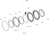
- the laundry treating device mainly includes the machine body, the door body 200 and the door-ring light-emitting assembly 100 for the laundry treating device according to the above-mentioned embodiments.
- the door body 200 is movably disposed to the machine body by means of a door hinge 90.
- the door body 200 mainly includes the door-ring light-emitting assembly 100, an anti-scald cover 40, a connecting member 60, a door back ring 70 and a glass bowl 80.
- the door-ring light-emitting assembly 100, the anti-scald cover 40, the connecting member 60, the door back ring 70, and the glass bowl 80 are disposed coaxially.
- the door-ring light-emitting assembly 100 is fixed to the glass bowl 80 by means of the connecting member 60, and the door back ring 70 is disposed at inner side of the door body 200 and fitted with the connecting member 60 and the glass bowl 80.
- the anti-scald cover 40 is arranged at an outer circumference side of the main trim 20 of the door-ring light-emitting assembly 100, so that damage to the user due to temperature rise of the main trim 20 of the door-ring light-emitting assembly 100 resulted by light rays illumination is prevented.
- the laundry treating device according to embodiments of the present disclosure also has the above-described technical effect, that is, by arranging the light source 10 between the auxiliary trim 30 and the main trim 20, the light rays transmitted by the light source 10 is reflected to the main reflection surface of the main trim 20 by means of the auxiliary reflection surface of the auxiliary trim 30, so that the light rays are distributed along the main reflection surface of the main trim 20, and the blooming effect of gradual changing and gradual weakening along the radial direction of the main reflection surface, which further enlarges visual range, enhances display effect, facilitates observation by the user, and improves user experience.
- the laundry treating device has a simple and compact structure, low manufacturing cost, is able to feed back the real-time state, and has the light escaping effect and better user experience.
- the terms “mounted,” “connected,” “coupled,” “fixed” and the like are used broadly, and may be, for example, fixed connections, detachable connections, or integral connections; may also be mechanical or electrical connections; may also be direct connections or indirect connections via intervening structures; may also be inner communications of two elements, which can be understood by those skilled in the art according to specific situations.
Landscapes
- Engineering & Computer Science (AREA)
- Textile Engineering (AREA)
- Vehicle Interior And Exterior Ornaments, Soundproofing, And Insulation (AREA)
- Illuminated Signs And Luminous Advertising (AREA)
Abstract
Description
- The present disclosure relates to a technical field of manufacturing of washing apparatus, particularly to a door-ring light-emitting assembly for a laundry treating device and a laundry treating device having the same.
- At present, a processing state of a washing apparatus is usually displayed by a display screen of the washing apparatus. However, users usually leave the washing apparatus after starting it and conduct other activities. In conditions of a long distance or poor night vision, it is difficult for the users to view the processing state on the display screen of the washing apparatus. In the related art, a light-emitting door ring of some washing apparatuses can display the processing state of the washing apparatus, but it is only able to display two states of washing and drying, cannot feed back a real-time operation state of the apparatus effectively, and has poor display effect.
- The present disclosure aims to solve at least one of the above-mentioned technical problems to some extent.
- Thus, the present disclosure provides a door-ring light-emitting assembly for a laundry treating device. The door-ring light-emitting assembly for the laundry treating device has a simple and compact structure and low manufacturing cost, is able to feed back a real-time operation state of an apparatus timely, has light escaping effect, facilitates observation by the user and has good user experience.
- The present disclosure further provides a laundry treating device having the above-mentioned door-ring light-emitting assembly.
- The door-ring light-emitting assembly for the laundry treating device according to embodiments of a first aspect of the present disclosure includes a main trim, an auxiliary trim, and a light source. The auxiliary trim is spaced apart from the main trim. The light source is arranged adjacent to the main trim. Light rays generated by the light source escape via a channel defined between the main trim and the auxiliary trim.
- With the door-ring light-emitting assembly for the laundry treating device according to embodiments of the present disclosure, by arranging the main trim and the auxiliary trim to be spaced apart and the light source to be adjacent to the maim trim, light rays escape via the channel between the main trim and the auxiliary trim, escaping effect is formed, which enlarges visual range of the light source, enhances display effect, facilitates observation by the user, and improves user experience. The door-ring light-emitting assembly for the laundry treating device has a simple and compact structure and low manufacturing cost, and has the light escaping effect and better user experience.
- In addition, the light-emitting assembly for the laundry treating device according to embodiments of the present disclosure can further has the following additional technical feature.
- According to some embodiments of the present disclosure, the main trim has a main reflection surface able to reflect light; the auxiliary trim has an auxiliary reflection surface able to reflect light, and the light rays generated by the light source escape via at least one of the main reflection surface and the auxiliary reflection surface.
- According to some embodiments of the present disclosure, the light rays generated by the light source escape via the auxiliary reflection surface of the auxiliary trim at first and the main reflection surface of the main trim then.
- According to some embodiments of the present disclosure, the main trim, the auxiliary trim and the light source are configured to be annular separately.
- According to some embodiments of the present disclosure, a section of the main trim is configured to have a first substantially L shape, and the main trim includes a first straight section and a first inclined section. The first straight section extends along an axial direction of the main trim, and the first inclined section is connected to an end of the first straight section and extends outwards along a radial direction of the main trim and inclinedly towards a side of the axial direction of the main trim, an outer surface of the first inclined section facing the side is configured to be the main reflection surface. The section of the auxiliary trim is configured to have a second substantially L shape, and the auxiliary trim includes a second straight section and a second inclined section. The second straight section extends along an axial direction of the auxiliary trim and is arranged coaxially with the first straight section. The second inclined section is connected to an end of the first straight section and extends outwards along a radial direction of the auxiliary trim and inclinedly towards the side of the axial direction of the auxiliary trim. An inner surface of the second inclined section facing away from the side is configured to be the auxiliary reflection surface.
- According to some embodiments of the present disclosure, the light source is arranged between the first straight section and the second straight section.
- According to some embodiments of the present disclosure, an inclined angle of the second inclined section with respect to the second straight section is greater than an inclined angle of the first inclined section with respect to the first straight section.
- According to some embodiments of the present disclosure, an outwards-extending length of the second inclined section is less than an outwards-extending length of the first inclined section.
- According to some embodiments of the present disclosure, the main reflection surface and the auxiliary reflection surface are configured to be an arc surface protruding towards the side separately.
- According to some embodiments of the present disclosure, the first straight section and the first inclined section are molded integrally, and the second straight section and the second inclined section are molded integrally.
- According to some embodiments of the present disclosure, the light-emitting assembly for the laundry treating device further includes a light uniformizing sheet, and the light uniformizing sheet is arranged between the light source and the auxiliary trim.
- According to some embodiments of the present disclosure, the auxiliary reflection surface is configured to be a white surface.
- According to some embodiments of the present disclosure, the light source is configured by a plurality of LED lights arranged continuously.
- The laundry treating device according to embodiments of the second aspect of the present disclosure includes a machine body, a door body, and a door-ring light-emitting assembly for a laundry treating device according to the above-mentioned embodiments. The door body can be movably disposed to the machine body, and the light-emitting assembly is arranged to the door body.
- With the laundry treating device according to embodiments of the present disclosure, by arranging the door-ring light-emitting assembly of the above-mentioned embodiments of the present disclosure to the door body, blooming effect of gradual changing and gradual weakening is formed by means of the light-emitting assembly, hence enlarging visual range of the light source, enhancing display effect, facilitating observation by the user, and improving user experience. The laundry treating device has a simple and compact structure and low manufacturing cost, and is able to feed back the real-time state timely and improve user experience.
- Additional aspects and advantages of embodiments of present disclosure will be given in part in the following descriptions, become apparent in part from the following descriptions, or be learned from the practice of the embodiments of the present disclosure.
- These and other aspects and advantages of embodiments of the present disclosure will become apparent and more readily appreciated from the following descriptions made with reference to the drawings, in which:
-
Fig. 1 is a schematic view of a door-ring light-emitting assembly for a laundry treating device in operation according to embodiments of the present disclosure. -
Fig. 2 is an exploded view of a door body of a laundry treating device according to embodiments of the present disclosure. -
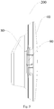
Fig. 3 is a sectional view of a door body of a laundry treating device according to embodiments of the present disclosure. -
Fig. 4 is an enlarged view of portion "A" illustrated inFig. 3 . -
Fig. 5 is an assembled view of a door body of a laundry treating device according to embodiments of the present disclosure. -
- 200:
- door body;
- 100:
- door-ring light-emitting assembly for laundry treating device;
- 10:
- light source;
- 20:
- main trim; 21: first inclined section; 22: first straight section;
- 30:
- auxiliary trim; 31: second inclined section; 32: second straight section;
- 50:
- light uniformizing sheet;
- 40:
- anti-scald cover;
- 60:
- connecting member;
- 70:
- door back ring;
- 80:
- glass bowl;
- 90:
- door hinge
- The embodiments of the present disclosure are described in detail below, and the examples of the embodiments are illustrated in the drawings, in which the same or similar reference numerals are configured to refer to the same or similar elements or elements having the same or similar functions. The embodiments described below with reference to the drawings are illustrative, intended to explain the present disclosure, and cannot be construed to limit the present disclosure.
- A door-ring light-emitting
assembly 100 for a laundry treating device according to embodiments of the first aspect of the present disclosure is described specifically in conjunction withFigs. 1 to 5 . - The door-ring light-emitting
assembly 100 for the laundry treating device according to embodiments of the present disclosure includes amain trim 20, anauxiliary trim 30 and alight source 10. - Specifically, the
auxiliary trim 30 and themain trim 20 are arranged spaced apart from each other, thelight source 10 is arranged adjacent to themain trim 20, and light rays generated by thelight source 10 escape via a channel defined between themain trim 20 and theauxiliary trim 30. - In other words, the door-ring light-emitting
assembly 100 for the laundry treating device mainly includes themain trim 20, theauxiliary trim 30 and thelight source 10. A section of themain trim 20 is configured to have a first substantially L shape and a front face (i.e. a front end face of themain trim 20 illustrated inFig. 1 ) of themain trim 20 forms into a curved face of a certain radian. A section of theauxiliary trim 30 is configured to have a second substantially L shape, and a back face of theauxiliary trim 30 forms into a curved face of a certain radian. Theauxiliary trim 30 and themain trim 20 are arranged spaced apart in an axial direction (a front-and-rear direction inFig. 1 ). The channel is defined between the back face of theauxiliary trim 30 and the front face of themain trim 20, and an extension line of a tangent line of the back face of theauxiliary trim 30 and an extension line of a tangent line of the front face of themain trim 20 intersect to form an included angle of a certain angle. Thelight source 10 is arranged between theauxiliary trim 30 and themain trim 20 along a left-and-right direction and adjacent to themain trim 20, and light rays generated by thelight source 10 escape via the channel between an auxiliary reflection surface and a main reflection surface. - Thus, with the door-ring light-emitting
assembly 100 for the laundry treating device according to embodiments of the present disclosure, by arranging themain trim 20 and theauxiliary trim 30 to be spaced apart, the channel is defined between themain trim 20 and theauxiliary trim 30; meanwhile, thelight source 10 is arranged adjacent to themain trim 20, so that light rays escape via the channel between themain trim 20 and theauxiliary trim 30, escaping effect is formed, which enlarges visual range for the light source, enhances display effect, facilitates observation by the user, and improves user experience. The door-ring light-emittingassembly 100 for the laundry treating device has a simple and compact structure, low manufacturing cost, and has the light escaping effect and better user experience. - In some specific embodiments of the present disclosure, the
main trim 20 has the main reflection surface which can reflect light, theauxiliary trim 30 has the auxiliary reflection surface which can reflect light, and light rays generated by thelight source 10 escape via at least one of the main reflection surface and the auxiliary reflection surface. - With reference to
Fig. 2 andFig. 4 , the section of themain trim 20 is configured to have the first substantially L shape, and the front face (i.e. the front end face of themain trim 20 illustrated inFig. 1 ) of themain trim 20 forms into the curved face (i.e. the main reflection surface) of a certain radian. The curved face of certain radian of themain trim 20 can reflect the light rays entering the curved face by being reflected by the back face (a rear end face of theauxiliary trim 20 illustrated inFig. 1 ) of theauxiliary trim 30, and can also directly reflect the light rays which escape from the channel, so that the light rays can be distributed gradiently along the curved face of certain radian of themain trim 20, the further the distance, the weaker the intensity of the light rays, so that blooming effect of gradual changing and gradual disappearing is exhibited. - Further, the section of the
auxiliary trim 30 is configured to have the second substantially L shape, and the back face of theauxiliary trim 30 forms into the curved face (i.e. the auxiliary reflection surface) of certain radian. The auxiliary reflection surface of theauxiliary trim 30 and the main reflection surface of themain trim 20 are arranged spaced apart in the axial direction (the front-and-rear direction inFig. 1 ). The extension line of the tangent line of the auxiliary reflection surface and the extension line of the tangent line of the main reflection surface intersect to form the included angle of certain angle. Thelight source 10 is arranged between theauxiliary trim 30 and themain trim 20 along the left-and-right direction, and light rays generated by thelight source 10 escape via the included angle between the auxiliary reflection surface and the main reflection surface, and are irradiated upon the main reflection surface of themain trim 20 after being reflected by the auxiliary reflection surface. - Thus, the transmitted light rays by the
light source 10 not only can be reflected to the main reflection surface of themain trim 20 by means of the auxiliary reflection surface of theauxiliary trim 30, but also can escape from the main reflection surface of themain trim 20, so that the light rays can be distributed along the main reflection surface of themain trim 20, thus forming blooming effect of gradual changing and gradual disappearing along a radial direction of the main reflection surface, hence enlarging visual range, enhancing display effect, facilitating observation by the user, and improving user experience. The door-ring light-emittingassembly 100 for the laundry treating device has the simple and compact structure, low manufacturing cost, is able to feed back the real-time state timely, and has the light escaping effect and better user experience. - The light rays generated by the light source escape via the auxiliary reflection surface of the
auxiliary trim 30 firstly and then the main reflection surface of themain trim 20. - With reference to
Fig. 1 , thelight source 10 is arranged between theauxiliary trim 30 and themain trim 20 along the left-and-right direction, the light rays generated by thelight source 10 can escape through the channel between the auxiliary reflection surface and the main reflection surface, and are irradiated upon the main reflection surface of themain trim 20 after being reflected by the auxiliary reflection surface, and then be reflected by the main reflection surface of themain trim 20 and escape from the main reflection surface of themain trim 20. - In some specific embodiments of the present disclosure, the
main trim 20, theauxiliary trim 30 and thelight source 10 are respectively configured to be annular. Specifically, as illustrated inFigs. 2 to 4 , theauxiliary trim 30, thelight source 10 and themain trim 20 are respectively configured to be annular and arranged coaxially, and light rays of the annularlight source 10 can be transmitted out through an included angle between theauxiliary trim 30 and themain trim 20, so that the light rays can be distributed along a circumferential direction after being reflected from the auxiliary reflection surface to the main reflection surface of themain trim 20, which further improves the uniformity of light rays and increases the visual range, enhancing the display effect. - The section of the
main trim 20 is configured to have the first substantially L shape and includes a firststraight section 22 and a firstinclined section 21. The firststraight section 22 extends along an axial direction of themain trim 20, and the firstinclined section 21 is connected to an end of the firststraight section 22 and extends outwards along a radial direction of themain trim 20 and inclinedly towards a side of the axial direction of themain trim 20, and an outer surface of the firstinclined section 21 facing the side is configured to be the main reflection surface. The section of theauxiliary trim 30 is configured to have the second substantially L shape, and theauxiliary trim 30 includes a secondstraight section 32 and a secondinclined section 31. The secondstraight section 32 extends along an axial direction of theauxiliary trim 30 and is arranged coaxially with the firststraight section 22. The secondinclined section 31 is connected to an end of the secondstraight section 32 and extends outwards along a radial direction of the auxiliary trim and inclinedly towards the side of the axial direction of theauxiliary trim 30. An inner surface of the secondinclined section 31 facing away from the side is configured to be the auxiliary reflection surface. - Specifically, as illustrated in
Figs. 1 to 4 , themain trim 20 mainly includes the firststraight section 22 and the firstinclined section 21, the section of themain trim 20 is configured to have the first substantially L shape, the firststraight section 22 extends along the axial direction (the front-and-rear direction as illustrated inFig. 1 ) of themain trim 20, and an end of the firstinclined section 21 is connected to a front end of the firststraight section 22, and the firstinclined section 21 extends outwards along the radial direction of the main reflection surface of themain trim 20 and inclinedly towards a side of an axial direction of the firstinclined section 21. The outer surface of the firstinclined section 21 facing the side in the axial direction is configured to be the main reflection surface, for example, as illustrated inFig. 1 , in the present embodiment, the firstinclined section 21 extends outwards along the radial direction of the main reflection surface of themain trim 20 and inclinedly forwards with respect to the axial direction (the front-and-rear direction inFig. 1 ) of the firstinclined section 21, and the front face (the front end face as illustrated inFig. 1 ) of the firstinclined section 21 is configured to be the main reflection surface. - Further, the
auxiliary trim 30 mainly includes the secondstraight section 32 and the secondinclined section 31. The section of theauxiliary trim 30 is configured to have the second substantially L shape, and the secondstraight section 32 extends along the axial direction (i.e. the front-and-rear direction as illustrated inFig. 1 ) of theauxiliary trim 30 and is arranged coaxially with the firststraight section 22. An end of the secondinclined section 31 is connected to a front end of the secondstraight section 32 and the secondinclined section 31 extends outwards along the radial direction of the auxiliary reflection surface of theauxiliary trim 30 and inclinedly towards the side of the axial direction of the secondinclined section 31. An outer surface of the secondinclined section 31 facing away from the side in the axial direction is configured to be the auxiliary reflection surface, for example, as illustrated inFig. 1 , in the present embodiment, the secondinclined section 31 extends outwards along the radial direction of the auxiliary reflection surface of theauxiliary trim 30 and inclinedly forwards with respect to the axial direction (the front-and-rear direction inFig. 1 ) of the secondinclined section 31, and the back face (the rear end surface as illustrated inFig. 1 ) of the secondinclined section 31 is configured to be the auxiliary reflection surface. - It is to be illustrated that "inner" can be construed as a side pointing towards a circle center in the radial direction of the
main trim 20, and the opposite direction is defined as "outer". - The
light source 10 is arranged between the firststraight section 22 and the secondstraight section 32. - Referring to
Fig. 1 , thelight source 10 is arranged between the firststraight section 22 and the secondstraight section 32 and adjacent to the firststraight section 22, so that the light rays of thelight source 10 can escape from the included angle between themain trim 20 and theauxiliary trim 30. After the reflection of the auxiliary reflection surface and the main reflection surface, the blooming effect of gradual changing and gradual weakening along the radial direction of the main reflection surface of themain trim 20 is formed. - In some specific embodiments of the present disclosure, an inclined angle of the second
inclined section 31 with respect to the secondstraight section 32 is greater than an inclined angle of the firstinclined section 21 with respect to the firststraight section 22. - Specifically, as illustrated in
Fig. 1 , themain trim 20 and theauxiliary trim 30 are arranged coaxially, the inclined angle of the firstinclined section 21 with respect to the firststraight section 22 is less than the inclined angle of the secondinclined section 31 with respect to the secondstraight section 32, so that it is ensured that the included angle of certain angle is formed between the extension line of the tangent line of the firstinclined section 21 and the extension line of the tangent line of the secondinclined section 31, thus increasing a range where the light rays are reflected to the main reflection surface of the firstinclined section 21 through the auxiliary reflection surface at the secondinclined section 31, and enhancing the blooming effect. - An outwards-extending length of the second
inclined section 31 is less than an outwards-extending length of the firstinclined section 21. Thus, not only it is ensured that the light rays can be reflected to the main reflection surface of the firstinclined section 21 through the auxiliary reflection surface of the secondinclined section 31, but also it is able to prevent the secondinclined section 31 from blocking the light rays reflected by the main reflection surface of the firstinclined section 21 to reduce the visual range of user. - The main reflection surface and the auxiliary reflection surface are configured to be an arc surface protruding towards the side separately.
- Referring to
Figs. 1 and4 , each of the main reflection surface and the auxiliary reflection surface protrudes forwards along the axial direction (the front-and-rear direction as illustrated inFig. 1 ) to form the arc surface, so that not only the range for light rays reflection can be increased, but also the light rays reflected on the main reflection surface can be distributed along the arc curved face of the main reflection surface and get weaken gradually along the radial direction of the main reflection surface, so that the visual range and the display effect can be increased. - Optionally, the first
straight section 22 and the firstinclined section 21 are molded integrally, and the secondstraight section 32 and the secondinclined section 31 are molded integrally. The integrally molded structure can not only ensure the connection reliability of various components, enhance structural strength of themain trim 20 and theauxiliary trim 30, but also simplify the manufacturing procedure due to convenient molding, so that the production efficiency of the door-ring light-emittingassembly 100 is increased. Certainly, the firststraight section 22 and the firstinclined section 21, the secondstraight section 32 and the secondinclined section 31 can also be assemblies in fixed connection, which is not limited in the present disclosure. - In addition, in some embodiments of the present disclosure, the door-ring light-emitting
assembly 100 for the laundry treating device further includes alight uniformizing sheet 50, and thelight uniformizing sheet 50 is arranged between thelight source 10 and theauxiliary trim 30. - Referring to
Fig. 4 , thelight uniformizing sheet 50 is arranged adjacent to thelight source 10 and between thelight source 10 and theauxiliary trim 30, so that with the light transmission and light diffusion property of thelight uniformizing sheet 50, the uniformity of light rays of thelight source 10 is improved, the formation of dark area is reduced, and the display effect of the door-ring light-emittingassembly 100 is enhanced. - The auxiliary reflection surface is configured to be a white surface. Thus, with the light reflection characteristic of white, the light rays of the
light source 10 can be reflected to the main reflection surface by the auxiliary reflection surface more fully, so that the reflection effect of the auxiliary reflection surface is enhanced, and hence the display effect and visual range of light rays on the main reflection surface is increased. - Optionally, the
light source 10 is configured by a plurality of LED lights arranged continuously. Thus, by providing the LED lights, not only brightening effect indicating different processing states of the laundry treating device is achieved and the real-time state of the laundry treating device is fed back to the user timely, but also the manufacturing cost of the door-ring light-emittingassembly 100 can be reduced effectively, and the service life can be increased. Certainly, annular lamp tube or other lamps can also be adopted as thelight source 10, which is not limited in the present disclosure. - The laundry treating device (not illustrated) according to embodiments of the second aspect of the present disclosure is described specifically with reference to
Figs. 1 to 5 . - The laundry treating device according to embodiments of the present disclosure includes a machine body (not illustrated), a
door body 200 and the door-ring light-emittingassembly 100 for the laundry treating device according to the above-mentioned embodiments. Thedoor body 200 can be movably disposed to the machine body, and the door-ring light-emittingassembly 100 is disposed to the door body. - In other words, the laundry treating device mainly includes the machine body, the
door body 200 and the door-ring light-emittingassembly 100 for the laundry treating device according to the above-mentioned embodiments. Thedoor body 200 is movably disposed to the machine body by means of adoor hinge 90. Thedoor body 200 mainly includes the door-ring light-emittingassembly 100, ananti-scald cover 40, a connectingmember 60, a door backring 70 and aglass bowl 80. The door-ring light-emittingassembly 100, theanti-scald cover 40, the connectingmember 60, the door backring 70, and theglass bowl 80 are disposed coaxially. The door-ring light-emittingassembly 100 is fixed to theglass bowl 80 by means of the connectingmember 60, and the door backring 70 is disposed at inner side of thedoor body 200 and fitted with the connectingmember 60 and theglass bowl 80. Theanti-scald cover 40 is arranged at an outer circumference side of themain trim 20 of the door-ring light-emittingassembly 100, so that damage to the user due to temperature rise of themain trim 20 of the door-ring light-emittingassembly 100 resulted by light rays illumination is prevented. - As the door-ring light-emitting
assembly 100 for the laundry treating device according to embodiments of the present disclosure has the above-mentioned technical effect, the laundry treating device according to embodiments of the present disclosure also has the above-described technical effect, that is, by arranging thelight source 10 between theauxiliary trim 30 and themain trim 20, the light rays transmitted by thelight source 10 is reflected to the main reflection surface of themain trim 20 by means of the auxiliary reflection surface of theauxiliary trim 30, so that the light rays are distributed along the main reflection surface of themain trim 20, and the blooming effect of gradual changing and gradual weakening along the radial direction of the main reflection surface, which further enlarges visual range, enhances display effect, facilitates observation by the user, and improves user experience. The laundry treating device has a simple and compact structure, low manufacturing cost, is able to feed back the real-time state, and has the light escaping effect and better user experience. - Other configurations of the door-ring light-emitting
assembly 100 for the laundry treating device and the laundry treating device having the door-ring light-emittingassembly 100 according to embodiments of the present disclosure are known to those ordinarily skilled in the art, which will not be described in detail here. - In the specification, it is to be understood that terms such as "central," "length," "width," "thickness," "front," "rear," "left," "right," "vertical," "horizontal," "inner," and "outer" should be construed to refer to the orientation as then described or as shown in the drawings under discussion. These relative terms are for convenience of description and do not require that the present disclosure be constructed or operated in a particular orientation, and cannot be construed to limit the present disclosure.
- In the present disclosure, unless specified or limited otherwise, the terms "mounted," "connected," "coupled," "fixed" and the like are used broadly, and may be, for example, fixed connections, detachable connections, or integral connections; may also be mechanical or electrical connections; may also be direct connections or indirect connections via intervening structures; may also be inner communications of two elements, which can be understood by those skilled in the art according to specific situations.
- Reference throughout this specification to "an embodiment," "some embodiments," "an example," "a specific example," or "some examples," means that a particular feature, structure, material, or characteristic described in connection with the embodiment or example is included in at least one embodiment or example of the present disclosure. Thus, the appearances of the phrases in various places throughout this specification are not necessarily referring to the same embodiment or example of the present disclosure. Furthermore, the particular features, structures, materials, or characteristics may be combined in any suitable manner in one or more embodiments or examples.
- Although explanatory embodiments have been shown and described, it would be appreciated by those skilled in the art that the above embodiments cannot be construed to limit the present disclosure, and changes, alternatives, variation, and modifications can be made in the embodiments without departing from spirit, principles and scope of the present disclosure.
Claims (14)
- A door-ring light-emitting assembly for a laundry treating device, comprising:a main trim;an auxiliary trim spaced apart from the main trim; anda light source arranged adjacent to the main trim, wherein light rays generated by the light source escape via a channel defined between the main trim and the auxiliary trim.
- The door-ring light-emitting assembly for the laundry treating device according to claim 1, wherein the main trim has a main reflection surface capable of reflecting light, the auxiliary trim has an auxiliary reflection surface capable of reflecting light, and the light rays generated by the light source escape via at least one of the main reflection surface and the auxiliary reflection surface.
- The door-ring light-emitting assembly for the laundry treating device according to claim 2, wherein the light rays generated by the light source escape via the auxiliary reflection surface of the auxiliary trim first and then the main reflection surface of the main trim.
- The door-ring light-emitting assembly for the laundry treating device according to claim 3, wherein the main trim, the auxiliary trim and the light source are configured to be annular separately.
- The door-ring light-emitting assembly for the laundry treating device according to claim 3 or 4, wherein a section of the main trim is configured to have a first substantially L shape, the main trim comprises a first straight section and a first inclined section, the first straight section extends along an axial direction of the main trim, the first inclined section is connected to an end of the first straight section and extends outwards along a radial direction of the main trim and inclinedly towards a side of the axial direction of the main trim, an outer surface of the first inclined section facing the side is configured to be the main reflection surface;
a section of the auxiliary trim is configured to have a second substantially L shape, the auxiliary trim comprises a second straight section and a second inclined section, the second straight section extends along an axial direction of the auxiliary trim and is arranged coaxially with the first straight section, the second inclined section is connected to an end of the second straight section and extends outwards along a radial direction of the auxiliary trim and inclinedly towards the side of the axial direction of the auxiliary trim, and an inner surface of the second inclined section facing away from the side is configured to be the auxiliary reflection surface. - The door-ring light-emitting assembly for the laundry treating device according to claim 5, wherein the light source is arranged between the first straight section and the second straight section.
- The door-ring light-emitting assembly for the laundry treating device according to claim 5, wherein an inclined angle of the second inclined section with respect to the second straight section is greater than an inclined angle of the first inclined section with respect to the first straight section.
- The door-ring light-emitting assembly for the laundry treating device according to claim 5, wherein an outwards-extending length of the second inclined section is less than an outwards-extending length of the first inclined section.
- The door-ring light-emitting assembly for the laundry treating device according to claim 5, wherein the main reflection surface and the auxiliary reflection surface are configured to be an arc surface protruding towards the side separately.
- The door-ring light-emitting assembly for the laundry treating device according to claim 5, wherein the first straight section and the first inclined section are molded integrally, and the second straight section and the second inclined section are molded integrally.
- The door-ring light-emitting assembly for the laundry treating device according to claim 6, further comprising a light uniformizing sheet arranged between the light source and the auxiliary trim.
- The door-ring light-emitting assembly for the laundry treating device according to any one of claims 1 to 11, wherein the auxiliary reflection surface is configured to be a white surface.
- The door-ring light-emitting assembly for the laundry treating device according to any one of claims 1 to 12, wherein the light source is configured by a plurality of LED lights arranged continuously.
- A laundry treating device, comprising:a machine body;a door body movably disposed to the machine body; anda door-ring light-emitting assembly for a laundry treating device according to any one of claims 1 to 13, wherein the light-emitting assembly is disposed to the door body.
Applications Claiming Priority (3)
| Application Number | Priority Date | Filing Date | Title |
|---|---|---|---|
| CN201610796727.4A CN107794719B (en) | 2016-08-31 | 2016-08-31 | Door ring light-emitting component of clothes treatment device and clothes treatment device with door ring light-emitting component |
| CN201621027962.7U CN206189132U (en) | 2016-08-31 | 2016-08-31 | Laundry treating apparatus's door circle light -emitting component and laundry treating apparatus who has it |
| PCT/CN2016/100913 WO2018040198A1 (en) | 2016-08-31 | 2016-09-29 | Door ring light-emitting assembly for laundry treating device, and laundry treating device having same |
Publications (3)
| Publication Number | Publication Date |
|---|---|
| EP3489408A1 true EP3489408A1 (en) | 2019-05-29 |
| EP3489408A4 EP3489408A4 (en) | 2019-06-19 |
| EP3489408B1 EP3489408B1 (en) | 2023-08-16 |
Family
ID=61299871
Family Applications (1)
| Application Number | Title | Priority Date | Filing Date |
|---|---|---|---|
| EP16914761.8A Active EP3489408B1 (en) | 2016-08-31 | 2016-09-29 | Door ring light-emitting assembly for laundry treating device, and laundry treating device having same |
Country Status (2)
| Country | Link |
|---|---|
| EP (1) | EP3489408B1 (en) |
| WO (1) | WO2018040198A1 (en) |
Families Citing this family (1)
| Publication number | Priority date | Publication date | Assignee | Title |
|---|---|---|---|---|
| DE102018007700A1 (en) * | 2018-09-28 | 2019-09-05 | Emz-Hanauer Gmbh & Co. Kgaa | Electric home appliance with a light window |
Family Cites Families (8)
| Publication number | Priority date | Publication date | Assignee | Title |
|---|---|---|---|---|
| EP1568816B1 (en) * | 2000-08-11 | 2008-04-30 | Arcelik A.S. | A washing machine with washing steps monitored remotely |
| DE102004015078A1 (en) * | 2004-03-25 | 2005-10-20 | Miele & Cie | Lighting device for a laundry treatment machine |
| JP4876876B2 (en) * | 2006-12-05 | 2012-02-15 | パナソニック株式会社 | Washing machine |
| JP2009213804A (en) * | 2008-03-13 | 2009-09-24 | Panasonic Corp | Drum type washing machine |
| DE102012212550A1 (en) * | 2012-07-18 | 2014-01-23 | BSH Bosch und Siemens Hausgeräte GmbH | Lighting device on a laundry care device |
| KR20140141099A (en) * | 2013-05-31 | 2014-12-10 | 삼성전자주식회사 | Washing machine and control method thereof |
| CN204311247U (en) * | 2014-12-11 | 2015-05-06 | 赵东晶 | Roller washing machine or dryer and door body assembly |
| CN205275986U (en) * | 2015-12-18 | 2016-06-01 | 德仕科技(深圳)有限公司 | Take washing machine observation window of light demonstration |
-
2016
- 2016-09-29 WO PCT/CN2016/100913 patent/WO2018040198A1/en not_active Ceased
- 2016-09-29 EP EP16914761.8A patent/EP3489408B1/en active Active
Also Published As
| Publication number | Publication date |
|---|---|
| WO2018040198A1 (en) | 2018-03-08 |
| EP3489408A4 (en) | 2019-06-19 |
| EP3489408B1 (en) | 2023-08-16 |
Similar Documents
| Publication | Publication Date | Title |
|---|---|---|
| EP3832197B1 (en) | Lampshade structure and lamp | |
| US20140252942A1 (en) | Lighting device with omnidirectional light distribution | |
| CN107795970A (en) | Household electrical appliance comprising illuminating module | |
| US9453622B2 (en) | Lens and LED module having the same | |
| US8764260B2 (en) | Light-guiding cover and illumination device having the same | |
| EP3489408B1 (en) | Door ring light-emitting assembly for laundry treating device, and laundry treating device having same | |
| CN106500021A (en) | Automobile Rear Position Lamp guide structure of the light inlet with coupling device | |
| US20220113001A1 (en) | Lamp | |
| US20130201693A1 (en) | Anti-glare lens | |
| CN203615246U (en) | LED illumination module | |
| CN206189132U (en) | Laundry treating apparatus's door circle light -emitting component and laundry treating apparatus who has it | |
| CN211650001U (en) | Lamp fitting | |
| CN212178562U (en) | Straight luminous type frame-free panel lamp | |
| CN107794719B (en) | Door ring light-emitting component of clothes treatment device and clothes treatment device with door ring light-emitting component | |
| EP3379135B1 (en) | Led lighting device having pipe shape | |
| TWI582353B (en) | Light emitting ring | |
| CN211650000U (en) | Light source module | |
| CN108072014A (en) | Lampshade and panel and cooking apparatus | |
| JP3174884U (en) | LED traffic light | |
| CN218729105U (en) | Structure improved fingerprint annular luminous module | |
| CN216113852U (en) | Novel uniform-light lens | |
| CN218355521U (en) | Lamp mirror | |
| CN223598598U (en) | Luminous switch | |
| CN223306771U (en) | Anti-glare lamps and lighting systems | |
| CN223953942U (en) | Light guide ring |
Legal Events
| Date | Code | Title | Description |
|---|---|---|---|
| STAA | Information on the status of an ep patent application or granted ep patent |
Free format text: STATUS: THE INTERNATIONAL PUBLICATION HAS BEEN MADE |
|
| PUAI | Public reference made under article 153(3) epc to a published international application that has entered the european phase |
Free format text: ORIGINAL CODE: 0009012 |
|
| STAA | Information on the status of an ep patent application or granted ep patent |
Free format text: STATUS: REQUEST FOR EXAMINATION WAS MADE |
|
| 17P | Request for examination filed |
Effective date: 20190221 |
|
| AK | Designated contracting states |
Kind code of ref document: A1 Designated state(s): AL AT BE BG CH CY CZ DE DK EE ES FI FR GB GR HR HU IE IS IT LI LT LU LV MC MK MT NL NO PL PT RO RS SE SI SK SM TR |
|
| AX | Request for extension of the european patent |
Extension state: BA ME |
|
| A4 | Supplementary search report drawn up and despatched |
Effective date: 20190516 |
|
| RIC1 | Information provided on ipc code assigned before grant |
Ipc: D06F 39/14 20060101AFI20190510BHEP |
|
| DAV | Request for validation of the european patent (deleted) | ||
| DAX | Request for extension of the european patent (deleted) | ||
| RAP1 | Party data changed (applicant data changed or rights of an application transferred) |
Owner name: WUXI LITTLE SWAN ELECTRIC CO., LTD. |
|
| STAA | Information on the status of an ep patent application or granted ep patent |
Free format text: STATUS: EXAMINATION IS IN PROGRESS |
|
| 17Q | First examination report despatched |
Effective date: 20210707 |
|
| GRAP | Despatch of communication of intention to grant a patent |
Free format text: ORIGINAL CODE: EPIDOSNIGR1 |
|
| STAA | Information on the status of an ep patent application or granted ep patent |
Free format text: STATUS: GRANT OF PATENT IS INTENDED |
|
| INTG | Intention to grant announced |
Effective date: 20230601 |
|
| GRAS | Grant fee paid |
Free format text: ORIGINAL CODE: EPIDOSNIGR3 |
|
| GRAA | (expected) grant |
Free format text: ORIGINAL CODE: 0009210 |
|
| STAA | Information on the status of an ep patent application or granted ep patent |
Free format text: STATUS: THE PATENT HAS BEEN GRANTED |
|
| AK | Designated contracting states |
Kind code of ref document: B1 Designated state(s): AL AT BE BG CH CY CZ DE DK EE ES FI FR GB GR HR HU IE IS IT LI LT LU LV MC MK MT NL NO PL PT RO RS SE SI SK SM TR |
|
| REG | Reference to a national code |
Ref country code: GB Ref legal event code: FG4D |
|
| REG | Reference to a national code |
Ref country code: CH Ref legal event code: EP Ref country code: DE Ref legal event code: R096 Ref document number: 602016082044 Country of ref document: DE |
|
| REG | Reference to a national code |
Ref country code: IE Ref legal event code: FG4D |
|
| REG | Reference to a national code |
Ref country code: LT Ref legal event code: MG9D |
|
| REG | Reference to a national code |
Ref country code: NL Ref legal event code: MP Effective date: 20230816 |
|
| REG | Reference to a national code |
Ref country code: AT Ref legal event code: MK05 Ref document number: 1600156 Country of ref document: AT Kind code of ref document: T Effective date: 20230816 |
|
| PG25 | Lapsed in a contracting state [announced via postgrant information from national office to epo] |
Ref country code: GR Free format text: LAPSE BECAUSE OF FAILURE TO SUBMIT A TRANSLATION OF THE DESCRIPTION OR TO PAY THE FEE WITHIN THE PRESCRIBED TIME-LIMIT Effective date: 20231117 |
|
| PG25 | Lapsed in a contracting state [announced via postgrant information from national office to epo] |
Ref country code: IS Free format text: LAPSE BECAUSE OF FAILURE TO SUBMIT A TRANSLATION OF THE DESCRIPTION OR TO PAY THE FEE WITHIN THE PRESCRIBED TIME-LIMIT Effective date: 20231216 |
|
| PG25 | Lapsed in a contracting state [announced via postgrant information from national office to epo] |
Ref country code: SE Free format text: LAPSE BECAUSE OF FAILURE TO SUBMIT A TRANSLATION OF THE DESCRIPTION OR TO PAY THE FEE WITHIN THE PRESCRIBED TIME-LIMIT Effective date: 20230816 Ref country code: RS Free format text: LAPSE BECAUSE OF FAILURE TO SUBMIT A TRANSLATION OF THE DESCRIPTION OR TO PAY THE FEE WITHIN THE PRESCRIBED TIME-LIMIT Effective date: 20230816 Ref country code: PT Free format text: LAPSE BECAUSE OF FAILURE TO SUBMIT A TRANSLATION OF THE DESCRIPTION OR TO PAY THE FEE WITHIN THE PRESCRIBED TIME-LIMIT Effective date: 20231218 Ref country code: NO Free format text: LAPSE BECAUSE OF FAILURE TO SUBMIT A TRANSLATION OF THE DESCRIPTION OR TO PAY THE FEE WITHIN THE PRESCRIBED TIME-LIMIT Effective date: 20231116 Ref country code: NL Free format text: LAPSE BECAUSE OF FAILURE TO SUBMIT A TRANSLATION OF THE DESCRIPTION OR TO PAY THE FEE WITHIN THE PRESCRIBED TIME-LIMIT Effective date: 20230816 Ref country code: LV Free format text: LAPSE BECAUSE OF FAILURE TO SUBMIT A TRANSLATION OF THE DESCRIPTION OR TO PAY THE FEE WITHIN THE PRESCRIBED TIME-LIMIT Effective date: 20230816 Ref country code: LT Free format text: LAPSE BECAUSE OF FAILURE TO SUBMIT A TRANSLATION OF THE DESCRIPTION OR TO PAY THE FEE WITHIN THE PRESCRIBED TIME-LIMIT Effective date: 20230816 Ref country code: IS Free format text: LAPSE BECAUSE OF FAILURE TO SUBMIT A TRANSLATION OF THE DESCRIPTION OR TO PAY THE FEE WITHIN THE PRESCRIBED TIME-LIMIT Effective date: 20231216 Ref country code: HR Free format text: LAPSE BECAUSE OF FAILURE TO SUBMIT A TRANSLATION OF THE DESCRIPTION OR TO PAY THE FEE WITHIN THE PRESCRIBED TIME-LIMIT Effective date: 20230816 Ref country code: GR Free format text: LAPSE BECAUSE OF FAILURE TO SUBMIT A TRANSLATION OF THE DESCRIPTION OR TO PAY THE FEE WITHIN THE PRESCRIBED TIME-LIMIT Effective date: 20231117 Ref country code: FI Free format text: LAPSE BECAUSE OF FAILURE TO SUBMIT A TRANSLATION OF THE DESCRIPTION OR TO PAY THE FEE WITHIN THE PRESCRIBED TIME-LIMIT Effective date: 20230816 Ref country code: AT Free format text: LAPSE BECAUSE OF FAILURE TO SUBMIT A TRANSLATION OF THE DESCRIPTION OR TO PAY THE FEE WITHIN THE PRESCRIBED TIME-LIMIT Effective date: 20230816 |
|
| PG25 | Lapsed in a contracting state [announced via postgrant information from national office to epo] |
Ref country code: PL Free format text: LAPSE BECAUSE OF FAILURE TO SUBMIT A TRANSLATION OF THE DESCRIPTION OR TO PAY THE FEE WITHIN THE PRESCRIBED TIME-LIMIT Effective date: 20230816 |
|
| PG25 | Lapsed in a contracting state [announced via postgrant information from national office to epo] |
Ref country code: ES Free format text: LAPSE BECAUSE OF FAILURE TO SUBMIT A TRANSLATION OF THE DESCRIPTION OR TO PAY THE FEE WITHIN THE PRESCRIBED TIME-LIMIT Effective date: 20230816 |
|
| PG25 | Lapsed in a contracting state [announced via postgrant information from national office to epo] |
Ref country code: SM Free format text: LAPSE BECAUSE OF FAILURE TO SUBMIT A TRANSLATION OF THE DESCRIPTION OR TO PAY THE FEE WITHIN THE PRESCRIBED TIME-LIMIT Effective date: 20230816 Ref country code: RO Free format text: LAPSE BECAUSE OF FAILURE TO SUBMIT A TRANSLATION OF THE DESCRIPTION OR TO PAY THE FEE WITHIN THE PRESCRIBED TIME-LIMIT Effective date: 20230816 Ref country code: ES Free format text: LAPSE BECAUSE OF FAILURE TO SUBMIT A TRANSLATION OF THE DESCRIPTION OR TO PAY THE FEE WITHIN THE PRESCRIBED TIME-LIMIT Effective date: 20230816 Ref country code: EE Free format text: LAPSE BECAUSE OF FAILURE TO SUBMIT A TRANSLATION OF THE DESCRIPTION OR TO PAY THE FEE WITHIN THE PRESCRIBED TIME-LIMIT Effective date: 20230816 Ref country code: DK Free format text: LAPSE BECAUSE OF FAILURE TO SUBMIT A TRANSLATION OF THE DESCRIPTION OR TO PAY THE FEE WITHIN THE PRESCRIBED TIME-LIMIT Effective date: 20230816 Ref country code: CZ Free format text: LAPSE BECAUSE OF FAILURE TO SUBMIT A TRANSLATION OF THE DESCRIPTION OR TO PAY THE FEE WITHIN THE PRESCRIBED TIME-LIMIT Effective date: 20230816 Ref country code: SK Free format text: LAPSE BECAUSE OF FAILURE TO SUBMIT A TRANSLATION OF THE DESCRIPTION OR TO PAY THE FEE WITHIN THE PRESCRIBED TIME-LIMIT Effective date: 20230816 |
|
| REG | Reference to a national code |
Ref country code: CH Ref legal event code: PL |
|
| PG25 | Lapsed in a contracting state [announced via postgrant information from national office to epo] |
Ref country code: LU Free format text: LAPSE BECAUSE OF NON-PAYMENT OF DUE FEES Effective date: 20230929 |
|
| REG | Reference to a national code |
Ref country code: DE Ref legal event code: R097 Ref document number: 602016082044 Country of ref document: DE |
|
| REG | Reference to a national code |
Ref country code: BE Ref legal event code: MM Effective date: 20230930 |
|
| PG25 | Lapsed in a contracting state [announced via postgrant information from national office to epo] |
Ref country code: LU Free format text: LAPSE BECAUSE OF NON-PAYMENT OF DUE FEES Effective date: 20230929 Ref country code: MC Free format text: LAPSE BECAUSE OF FAILURE TO SUBMIT A TRANSLATION OF THE DESCRIPTION OR TO PAY THE FEE WITHIN THE PRESCRIBED TIME-LIMIT Effective date: 20230816 |
|
| PLBE | No opposition filed within time limit |
Free format text: ORIGINAL CODE: 0009261 |
|
| STAA | Information on the status of an ep patent application or granted ep patent |
Free format text: STATUS: NO OPPOSITION FILED WITHIN TIME LIMIT |
|
| REG | Reference to a national code |
Ref country code: IE Ref legal event code: MM4A |
|
| PG25 | Lapsed in a contracting state [announced via postgrant information from national office to epo] |
Ref country code: IE Free format text: LAPSE BECAUSE OF NON-PAYMENT OF DUE FEES Effective date: 20230929 |
|
| PG25 | Lapsed in a contracting state [announced via postgrant information from national office to epo] |
Ref country code: CH Free format text: LAPSE BECAUSE OF NON-PAYMENT OF DUE FEES Effective date: 20230930 |
|
| 26N | No opposition filed |
Effective date: 20240517 |
|
| GBPC | Gb: european patent ceased through non-payment of renewal fee |
Effective date: 20231116 |
|
| PG25 | Lapsed in a contracting state [announced via postgrant information from national office to epo] |
Ref country code: IT Free format text: LAPSE BECAUSE OF FAILURE TO SUBMIT A TRANSLATION OF THE DESCRIPTION OR TO PAY THE FEE WITHIN THE PRESCRIBED TIME-LIMIT Effective date: 20230816 Ref country code: IE Free format text: LAPSE BECAUSE OF NON-PAYMENT OF DUE FEES Effective date: 20230929 Ref country code: FR Free format text: LAPSE BECAUSE OF NON-PAYMENT OF DUE FEES Effective date: 20231016 Ref country code: CH Free format text: LAPSE BECAUSE OF NON-PAYMENT OF DUE FEES Effective date: 20230930 Ref country code: SI Free format text: LAPSE BECAUSE OF FAILURE TO SUBMIT A TRANSLATION OF THE DESCRIPTION OR TO PAY THE FEE WITHIN THE PRESCRIBED TIME-LIMIT Effective date: 20230816 |
|
| PG25 | Lapsed in a contracting state [announced via postgrant information from national office to epo] |
Ref country code: BE Free format text: LAPSE BECAUSE OF NON-PAYMENT OF DUE FEES Effective date: 20230930 |
|
| PG25 | Lapsed in a contracting state [announced via postgrant information from national office to epo] |
Ref country code: GB Free format text: LAPSE BECAUSE OF NON-PAYMENT OF DUE FEES Effective date: 20231116 |
|
| PG25 | Lapsed in a contracting state [announced via postgrant information from national office to epo] |
Ref country code: GB Free format text: LAPSE BECAUSE OF NON-PAYMENT OF DUE FEES Effective date: 20231116 |
|
| PG25 | Lapsed in a contracting state [announced via postgrant information from national office to epo] |
Ref country code: BG Free format text: LAPSE BECAUSE OF FAILURE TO SUBMIT A TRANSLATION OF THE DESCRIPTION OR TO PAY THE FEE WITHIN THE PRESCRIBED TIME-LIMIT Effective date: 20230816 |
|
| PG25 | Lapsed in a contracting state [announced via postgrant information from national office to epo] |
Ref country code: BG Free format text: LAPSE BECAUSE OF FAILURE TO SUBMIT A TRANSLATION OF THE DESCRIPTION OR TO PAY THE FEE WITHIN THE PRESCRIBED TIME-LIMIT Effective date: 20230816 |
|
| PG25 | Lapsed in a contracting state [announced via postgrant information from national office to epo] |
Ref country code: CY Free format text: LAPSE BECAUSE OF FAILURE TO SUBMIT A TRANSLATION OF THE DESCRIPTION OR TO PAY THE FEE WITHIN THE PRESCRIBED TIME-LIMIT; INVALID AB INITIO Effective date: 20160929 |
|
| PG25 | Lapsed in a contracting state [announced via postgrant information from national office to epo] |
Ref country code: HU Free format text: LAPSE BECAUSE OF FAILURE TO SUBMIT A TRANSLATION OF THE DESCRIPTION OR TO PAY THE FEE WITHIN THE PRESCRIBED TIME-LIMIT; INVALID AB INITIO Effective date: 20160929 |
|
| PGFP | Annual fee paid to national office [announced via postgrant information from national office to epo] |
Ref country code: DE Payment date: 20250923 Year of fee payment: 10 |
|
| PG25 | Lapsed in a contracting state [announced via postgrant information from national office to epo] |
Ref country code: TR Free format text: LAPSE BECAUSE OF FAILURE TO SUBMIT A TRANSLATION OF THE DESCRIPTION OR TO PAY THE FEE WITHIN THE PRESCRIBED TIME-LIMIT Effective date: 20230816 |