EP3489398B1 - Open-end spinning machine with improved yarn waste discharge device and related yarn waste discharge method - Google Patents
Open-end spinning machine with improved yarn waste discharge device and related yarn waste discharge method Download PDFInfo
- Publication number
- EP3489398B1 EP3489398B1 EP18204945.2A EP18204945A EP3489398B1 EP 3489398 B1 EP3489398 B1 EP 3489398B1 EP 18204945 A EP18204945 A EP 18204945A EP 3489398 B1 EP3489398 B1 EP 3489398B1
- Authority
- EP
- European Patent Office
- Prior art keywords
- trolley
- open
- storage tank
- spinning machine
- waste
- Prior art date
- Legal status (The legal status is an assumption and is not a legal conclusion. Google has not performed a legal analysis and makes no representation as to the accuracy of the status listed.)
- Active
Links
Images




Classifications
-
- D—TEXTILES; PAPER
- D01—NATURAL OR MAN-MADE THREADS OR FIBRES; SPINNING
- D01H—SPINNING OR TWISTING
- D01H4/00—Open-end spinning machines or arrangements for imparting twist to independently moving fibres separated from slivers; Piecing arrangements therefor; Covering endless core threads with fibres by open-end spinning techniques
- D01H4/48—Piecing arrangements; Control therefor
Definitions
- the present invention preferably provides for the use of at least one piecing trolley 76 for each machine side A, B to allow all the trolleys 76 of each machine side A, B to be able to discharge the fluff storage tank 52.
Landscapes
- Engineering & Computer Science (AREA)
- Mechanical Engineering (AREA)
- Textile Engineering (AREA)
- Spinning Or Twisting Of Yarns (AREA)
Description
- The present invention relates to an open-end spinning machine with an improved device for discarding the yarn waste and the relative method for discharging the yarn waste in an open-end spinning machine.
- As is known, during the spinning process it may happen that a breakdown of the produced yarn occurs in the spinning machines, with consequent interruption of the yarn production. The restoration of this activity involves the junction between two portions of yarn: the one produced before the break, which is wound on the reel, and the amount that will be generated when the spinning resumes.
- In general, in the textile the procedure that joins the ends of the thread is carried out through the piecing cycle (or simply piecing).
- During the piecing cycle it is necessary to provide a suction system whose purpose is both to retain the yarn in order to handle it and to evacuate any waste produced in the processing (fluff, duct, yarn fibres, etc.).
- Known open end spinning machines can be completely automatic, in which the doffing and piecing cycles are carried out by a single trolley.
- Within this single trolley, some devices are designed for the single doffing cycle of a reel, while others are used for the yarn piecing cycle.
- In known machines of the fully automatic type, when said single trolley reaches the spinning unit where intervention is required, it connects with the centralized suction system of the machine. The machine is in fact provided with a suction channel that develops horizontally above the spinning units, in proximity and parallel to the trolley translation tracks. This channel is aeraulically connected to the main suction system of the machine.
- Concurrently with each individual spinning head there is a horizontal axis throttle gate, through the pivoting of which the suction channel can be accessed to interface with each other.
- When necessary, the trolley opens the throttle gate and operates a telescopic nozzle with which it connects to the suction channel. In this way the trolley has available the vacuum needed to operate the devices mounted on the trolley itself.
- In this way, all the waste sucked by the reel suction mouth, by the preparer and by the other service mouths mounted on the trolley, pass through the suction channel and end directly to the machine's main suction system. Once the operations for which suction is necessary have ended, the trolley retracts the telescopic suction mouth and closes the throttle gate.
- Therefore, all the most advanced machines available on the market today directly use the centralized suction system of the machine, thus requiring a system of ducts and mouths to allow the relative pneumatic connection in every single working position of the trolley.
- Therefore, the known solutions described above have drawbacks and limitations, essentially due to the fact that they provide for the use of complex and expensive systems of ducts and mouths which, in addition to increasing the complexity and costs of the machine, also increase the time required to discharge the yarn waste. Such known solutions are disclosed, for example, by
JP H0551828 A EP 0442049 A2 ,EP 2508659 A1 ,EP 2530193 A1 ,EP 2305864 A1 . - The need to solve the drawbacks and limitations mentioned with reference to the prior art is therefore felt.
- This need is met by an open-end spinning machine according to claim 1 and by a method for discharging yarn waste from an open-end spinning machine according to claim 13.
- Further features and advantages of the present invention will appear more clearly from the following description of preferred non-limiting embodiments thereof, in which:
-
figure 1 shows a schematic plan view of a part of an open-end type spinning machine according to an embodiment of the present invention; -
figure 2 shows a plan view of the enlarged detail II infigure 1 ; -
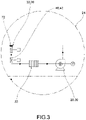
figure 3 shows a plan view of the enlarged detail III infigure 1 ; -
figure 4 shows a schematic plan view of a part of a side of an open-end type spinning machine according to an embodiment of the present invention; -
figure 5 shows a plan view of the enlarged detail V infigure 4 ; -
figure 6 shows a cross sectional view of a spinning machine according to an embodiment of the present invention; -
figure 7 shows a perspective view of a service trolley of a spinning machine according to the present invention; -
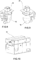
figures 8-9 show perspective views, from different angles, of a secondary suction device mounted on a service trolley according to the present invention; -
figure 10 shows a perspective view of a part of a centralized or main suction system of the spinning machine according to the present invention; -
figures 11-12 show perspective views of a yarn waste reception duct of the main suction system according to an embodiment of the present invention, in a retracted and extracted configuration, respectively; -
figures 13-14 show perspective views of a main or secondary shut-off valve, according to an embodiment of the present invention, in closed and open configuration, respectively. - Elements, or parts of elements, in common to the embodiments described below are referred to with the same reference numerals.
- With reference to the above figures,
reference numeral 4 globally indicates an overall schematic view of an open-end type spinning apparatus according to the present invention. - In particular, the
spinning machine 4 comprises at least one spinninghead 8 having aspinning unit 12 and areel winding unit 16, wherein thereel winding unit 16 wraps on a tube 20 a reel of yarn obtained from theunderlying spinning unit 12. - The
spinning machine 4 further comprises a centralized ormain suction system 24 having vacuum generating means 28 for themachine 4, such as typically a fan 30 and at least onefilter 33. - The
centralized suction system 24 is provided with areception duct 32 of the yarn waste, such as fluff, dust and/or yarn fibres, having aninput mouth 36 aeraulically connectable to said vacuum generating means 28 by means of a main shut-offvalve 40. - Preferably, the main shut-off
valve 40 is a diaphragm-type shut-off valve, having an obturator insectors 42. - The use of an obturator in
sectors 42 avoids the generation of sudden fluid dynamic impulses which would result in damaging water hammers inside the suction ducts of thespinning machine 4. - Furthermore, the
centralized suction system 24 is provided with at least oneservice trolley 44 mobile so as to be placed in the vicinity of each spinninghead 8 and fitted with its ownsecondary suction device 48 able to generate a vacuum to aspirate yarn waste from each spinninghead 8. - Advantageously, the
secondary suction device 48 is fitted with itsown storage tank 52 for collecting the aspirated yarn waste, and itsown discharge duct 56 suitable to allow the selective emptying of the waste accumulated in saidstorage tank 52. - The
discharge duct 56 is in turn fitted with adischarge mouth 60 and a secondary shut-off valve 64 configured to interact selectively with theinput mouth 36 of thewaste reception duct 32 and/or with the main shut-offvalve 40. - Preferably, the
storage tank 52 is arranged immediately below the corresponding secondary suction device 48: in this way, the waste sucked by the suction mouth can fall directly due to gravity inside thestorage tank 52. - According to a possible embodiment, the secondary shut-off valve 64 is a diaphragm-type shut-off valve, having an obturator in sectors 68, of the same type as that of which the main shut-off
valve 40 is provided. - The use of an obturator in sectors 68 avoids the generation of sudden fluid dynamic impulses which would result in damaging water hammers inside the suction ducts of the
spinning machine 4. - Preferably, the secondary shut-off valve 64 is arranged downstream of the
storage tank 52 and upstream of thedischarge duct 56. - As seen, the yarn waste must be sent from the
discharge duct 56 to thereception duct 32 of thecentralized suction system 4. - According to the invention, the yarn
waste reception duct 32 is of the mobile and/or telescopic type so as to pass from a retracted configuration (figure 11 ) in which it does not interface with thedischarge duct 56 of theservice trolley 44 to an extracted configuration (figure 12 ) in which it connects aeraulically with saiddischarge duct 56. - Preferably, the
input mouth 36 of the yarnwaste reception duct 32 is provided with at least onegasket 72 to achieve a seal with thedischarge mouth 60 of thedischarge duct 56. - Preferably, said
gasket 72 is of the suction cup type. - As mentioned, the
spinning machine 4 comprises at least oneservice trolley 44; preferably, theservice trolley 44 is apiecing trolley 76 comprising suction and gripping means of a broken end of yarn and means of piecing said broken yarn (not shown). - According to a possible embodiment, the
spinning machine 4 comprises, as afurther service trolley 44, at least one doffing trolley 80 which can be positioned at eachspinning unit 12 and fitted with devices for picking up and moving atube 20 from a tube-holder basket to a pair of tailstocks of the winding unit into reels. - Advantageously, the
piecing trolley 76 and the doffing trolley 80 are distinct and independent from each other. - Preferably (
figure 6 ), thepiecing trolley 76 and doffing trolley 80 at least partially penetrate each other in order to mutually override each other along a patrol path of the spinningheads 8 of thespinning machine 4. - In other words, the
piecing trolley 76 and the doffing trolley 80 have a shape and follow a trajectory such that they can meet in any intermediate section and cross it, that is, climb it, without disturbing each other. - According to a preferred embodiment, the
spinning machine 4 comprises at least two distinct piecing trolleys 76', 76'', each with its ownsecondary suction device 48', 48", itsown storage tank 52', 52" and itsown discharge duct 56', 56", so that eachpiecing trolley 76', 76" can patrol a specific side A, B of thespinning machine 4. - The operation of an open-end spinning machine according to the present invention will now be described.
- In particular, the
spinning machine 4 operates continuously, producing yarn through thespinning unit 12; in the meantime, theservice trolley 44, typically thepiecing trolley 76, patrols thevarious spinning units 12 and, if necessary, performs all the required piecing operations. During its operation, thepiecing trolley 76 continues to suck up yarn waste which is conveyed, through the vacuum created by thesecondary suction device 48, into thestorage tank 52. - Obviously, the independence and autonomy of the
piecing trolley 76 from the rest of thespinning machine 4 in carrying out its functions is limited by the volume of thestorage tank 52, which is why at a certain point it will be necessary to proceed with the emptying of the collection container. - This discharge is then carried out automatically.
- In particular, when it is possible to empty the fluff storage tank 52 (according to the criteria indicated below), the management software of the spinning
machine 4 activates the automatic cleaning cycle. The piecingtrolley 76 moves to a precise point of the spinningmachine 4, that is, at thecentralized suction system 24, where it is possible to carry out the waste discharge. In fact, the centralized suction system is connected to thereception duct 32 described above, which allows the piecingtrolley 76 to be able to discharge the waste accumulated during the various cycles, thus releasing thefluff storage tank 52. - The piecing
trolley 76 stops in the exact position where it is possible to discharge, for example due to an identification system by means of an optical bar code reader, which is normally used to precisely locate the spinningunits 12 on which to operate. - After alignment between the
discharge duct 56 of the piecingtrolley 76 and thecorresponding reception duct 32 of thecentralized suction system 24, the software for managing the spinningmachine 4 activates the movement of thereception duct 32. For example, saidreception duct 32 is provided with a telescopic system: an electric stepper motor rotates a nut screw, for example with a trapezoidal thread, allowing translation of theinput mouth 36 of thereception duct 32, which projects from the side of the spinningmachine 4 to reach theadjacent piecing trolley 76. - Preferably, as seen, the terminal or
input mouth 36 of such areception duct 32 is provided with agasket 72, preferably suction cup type, which allows the ends of thereception duct 32 and of thedischarge duct 56, respectively, to mate thus ensuring a good pneumatic seal. In this way, the continuity and the aeraulic connection between thedischarge duct 56 and thereception duct 32 are achieved. - The other end of the
reception duct 32 is connected to the suction channel of thecentralized suction system 24 of the technological air of the spinningmachine 4 . - The
reception duct 32 is in turn provided in an intermediate position with a main shut-offvalve 40 with an obturator insectors 42, of the same type as the secondary shut-off valve 64 mounted on thedischarge duct 56 on the side of the piecingtrolley 76. - When the respective ends of the
discharge ducts 56 and of thereception duct 32 are connected to each other, the actual yarn waste discharge cycle begins: the main shut-offvalve 40 opens slowly so as not to generate undesired fluid dynamic impulses in thereception duct 32. The secondary shut-off valve 64 then opens, mounted on the piecingtrolley 76, taking the same care, in order to avoid the occurrence of water hammer phenomena. - The
fluff storage tank 52 will now be in high vacuum and all of its contents will flow rapidly through thedischarge ducts 56 and the related secondary shut-off valves 64 and main shut-offvalves 40; from here, through the main air suction channel of the technological air, the waste will end up in the filter of the spinningmachine 4 where it can be easily collected together with the other waste and removed by known and universally adopted systems. - Once the
fluff storage tank 52 has been emptied, the secondary shut-off valve 64 on board the piecingtrolley 76 is closed again, after which the main shut-offvalve 40 of thecentralized suction system 24 is also closed, after which the telescopic connection of theinput mouth 36 of thereception duct 32 of thecentralized suction system 24 is retracted into the footprint of the machine. - At this point, the piecing
trolley 76 is free to leave thecentralized suction system 24 resuming its patrolling activities of the various spinning heads 8. - As mentioned above, the present invention preferably provides for the use of at least one piecing
trolley 76 for each machine side A, B to allow all thetrolleys 76 of each machine side A, B to be able to discharge thefluff storage tank 52. - The present invention also relates to the criteria for emptying the
storage tank 52, i.e. the control logic for activating the emptying procedures by means of theservice trolleys 44. - In fact, the choice of when to start the emptying cycle of the
fluff storage tank 52 is fundamental with a view to optimizing overall machine times. - The main idea is to not specifically send the piecing
trolley 76 to thecentralized suction system 24 to follow only the waste discharge, so that it is not in the condition in which thestorage tank 52 has reached its limit filling capacity. Preferably, it is contemplated to anticipate the overflow condition of thestorage tank 52 and to exploit one of the movements of the piecingtrolley 76 in which the same should pass through the section of thecentralized suction system 24 or in which it would operate on aspinning unit 12 located close to saidcentralized suction system 24. - At this point, taking advantage of the proximity, the piecing
trolley 76 could approach thecentralized suction system 24 and perform the waste discharge procedure. - In any case, in order to be able to determine when it is more convenient to send the piecing
trolley 76 to the fluff discharge, a criterion must be set on the machine management software with which to evaluate when it is necessary to empty thefluff storage tank 52. - For the purposes of the present invention, there are several criteria that can be used to set the emptying, namely:
- I. time-based;
- II. with the number of piecing made;
- III. by estimating the fullness of the
storage tank 52 with a volumetric sensor on the tank itself; - IV. by estimating the fullness of the
storage tank 56 with a pressure gauge on the aspirator on board theservice trolley 44; - V. by estimating the fullness of the
storage tank 56 by detecting the electricity consumption of the motor supplying motion to thesecondary suction device 48 on board theservice trolley 44. - With the 'time-based' criterion a time interval is set between one discharge and the other: this method can be implemented without the need for additional control devices.
- With the principle of the number of piecing, the
service trolley 44 is forced to carry out the discharge of the fluff at predetermined intervention intervals: also in this case no further control devices are required. - With a volumetric sensor installed on the
fluff storage tank 52, the machine could have a more precise control as it would be able to have a more precise estimate of the amount of waste collected. - The pressure gauge installed on the suction mouth of the
secondary suction device 48 would allow evaluating when the machine is too 'straining' due to a toofull storage tank 52. - Also the measurement of current consumption of the motor which moves the impeller of the
secondary suction device 48 has the advantage that it does not require any additional device as consumption is a data already known to the management software. - In the machine of the present invention, preferably the emptying step is activated according to one or more of the above mentioned criteria which can be implemented either individually or in combination with each other.
- As can be appreciated from what has been described, the open-end spinning machine and the method of waste discharge from an open-end spinning machine according to the invention allow overcoming the drawbacks of the prior art.
- The new fluff discharge system has several advantages over all the prior art solutions currently present on the market.
- The main advantages introduced are the following:
- reduction of the suction system;
- reduction of load losses;
- reduction of the trolley intervention times;
- better efficiency in the overall management of the machine.
- The above advantages are better explained hereinafter.
- In particular, the reduction of the suction system is a consequence of the fact that the entire system of secondary ducts and mouths (one for each spinning head) necessary to allow the connection of the trolley in each working position with the centralized suction system is no longer required. With the present invention, the extension of the secondary duct is reduced considerably (even by half of the current open-end marketed by the same applicant) and the interconnection mouths between the machine and the piecing trolley are reduced to two (one for each side). The benefit will also result in maintenance: in fact, fewer components offer less chance of breakage.
- The reduction described above not only entails benefits in terms of reducing machine and maintenance costs, but also benefits in pneumatic terms.
- In fact, the overall reduction in the number of mouths also leads to a reduction in pressure losses (localized losses introduced by each individual mouth) but above all to a clear reduction of the distributed losses due to the extra length of duct necessary to reach the outermost mouths, that is, the mouths farthest from the centralized suction system (used in known solutions).
- The reduction in the intervention time of the trolley is due to the fact that at the beginning of each piecing cycle that the trolley must perform, it will no longer be necessary to dedicate machine time to the opening step of the throttle valve and to the pneumatic connection of the telescopic mouth; furthermore, at the end of the cycle it will not be necessary to spend more time to disconnect the telescopic mouth and close the aforementioned throttle valve. These operations will be carried out anyway but with a frequency much lower than the solutions of the prior art.
- The best efficiency in machine management refers to the fact that in the known systems previously adopted, when the filter of the centralized suction system needs to be cleaned, the action of the trolleys on both sides of the machine is inhibited, as the suction is completely interrupted.
- With the present invention, the trolley works with its own suction system independent of that of the machine, until it is necessary to discharge the fluff: in this way, the trolley can operate even if the central vacuum is in the filter cleaning step.
- A man skilled in the art may make several changes and adjustments to the machines and methods of the present invention in order to meet specific and incidental needs, all falling within the scope of protection defined in the following claims.
Claims (17)
- Open-end spinning machine (4) comprising at least one spinning head (8) having a spinning unit (12) and a winding unit into reels (16), wherein the winding unit into reels (16) winds onto a tube (20) a reel of yarn obtained from the underlying spinning unit (12),- a main suction system (24) of the spinning machine (4), with means for producing a vacuum (28) for the machine (4) and provided with a reception duct (32) of the yarn waste, such as fluff, dust and/or yarn fibres, with an input mouth (36) aeraulically connectable to said vacuum generating means (28) by means of a main shut-off valve (40),- at least one service trolley (44) mobile so as to be placeabale in the vicinity of each spinning head (8), the service trolley being fitted with its own secondary suction device (48) able to generate a vacuum to aspirate yarn waste from each spinning head (8),
wherein- the secondary suction device (48) is fitted with its own storage tank (52) for collecting the aspirated yarn waste, and its own discharge duct (56) suitable to allow the selective emptying of the waste accumulated in said storage tank (52),- the discharge duct (56) being fitted with a discharge mouth (60) and a secondary shut-off valve (64) configured to interact selectively with the input mouth (36) of the waste reception duct (32) and/or with the main shut-off valve (40), wherein the yarn waste reception duct (32) is of the mobile and/or telescopic type so as to pass from a retracted configuration in which it does not interface with the discharge duct (56) of the service trolley (44) to an extracted configuration in which it connects aeraulically with said discharge duct (56) in order to allow the passage of the waste from the collection tank (52) into the centralised suction system (24). - Open-end spinning machine (4) according to claim 1, wherein the storage tank (52) is placed immediately below the corresponding secondary suction device (48).
- Open-end spinning machine (4) according to claim 1 or 2, wherein the secondary shut-off valve (64) is a diaphragm-type shut-off valve, having an obturator in sectors (68).
- Open-end spinning machine (4) according to any of the preceding claims, wherein the secondary shut-off valve (64) is placed downstream of the storage tank (52) and upstream of the discharge duct (56).
- Open-end spinning machine (4) according to any of the preceding claims, wherein the input mouth (36) of the yarn waste reception duct (32) is provided with at least one gasket (72) to achieve a seal with the discharge mouth (60) of the discharge duct (56).
- Open-end spinning machine (4) according to claim 5, wherein said gasket (72) is of the suction cup kind.
- Open-end spinning machine (4) according to any of the preceding claims, wherein the main shut-off valve (40) is a diaphragm-type shut-off valve, having an obturator in sectors (42) .
- Open-end spinning machine (4) according to any of the preceding claims, wherein the service trolley (44) is a piecing trolley (76) comprising suction and gripping means of a broken end of yarn and means of piecing said broken yarn.
- Open-end spinning machine (4) according to any of the preceding claims, wherein the machine comprises at least one doffing trolley (80) which can be positioned at each spinning unit (12) and fitted with devices for picking up and moving a tube (20) from a tube-holder basket to a pair of tailstocks of the winding unit into reels (16).
- Open-end spinning machine (4) according to claim 8 in conjunction with claim 9, wherein the trolley (44) coincides with the piecing trolley (76), said piecing trolley (76) and doffing trolley (80) being separate and independent of each other.
- Open-end spinning machine (4) according to claim 10, wherein the piecing trolley (76) and doffing trolley (80) at least partially penetrate each other in order to mutually override each other along a patrol path of the spinning heads (8) of the machine (4).
- Open-end spinning machine (4) according to any of the preceding claims, comprising at least two distinct piecing trolleys (76',76'') such as service trolleys, each with its own secondary suction device (48',48 "), its own storage tank (52', 52") and its own discharge duct (56', 56''), each trolley (76', 76") patrolling a specific side (A, B) of the spinning machines (4).
- Method of discharging yarn waste from an open-end spinning machine (4) comprising the steps of:- providing an open-end spinning machine (4) comprising at least one spinning head (8) having a spinning unit (12) and a winding unit into reels (16), wherein the winding unit into reels (16) winds onto a tube (20) a reel of yarn obtained from the underlying spinning unit (12),- providing a main suction system (24) of the spinning apparatus (4), with means of producing a vacuum (28) for the machine (4) and provided with a reception duct (32) of the yarn waste, such as fluff, dust and/or yarn fibres, with an input mouth (36) aeraulically connectable to said vacuum generating means (28) by means of a main shut-off valve (40),- providing at least one service trolley (44) mobile so as to be placeable in the vicinity of each spinning head (8), the service trolley (44) being fitted with its own secondary suction device (48) able to generate a vacuum to aspirate yarn waste from each spinning head (8),- fitting the secondary suction device (48) with its own storage tank (52) for collecting the aspirated yarn waste, and its own discharge duct (56) suitable to allow the selective emptying of the waste accumulated in said storage tank (52), wherein the yarn waste reception duct (32) is of the mobile and/or telescopic type so as to pass from a retracted configuration in which it does not interface with the discharge duct (56) of the service trolley (44) to an extracted configuration in which it connects aeraulically with said discharge duct (56),- fitting the discharge pipe (56) with a discharge mouth (60) and a secondary shut-off valve (64) configured to interact selectively with the input mouth (36) of the waste reception duct (32) and/or with the main shut-off valve (40),- selectively emptying the storage tank (52) after aeraulically connecting the discharge duct (56) of the secondary suction device (48) of the service trolley (44) with the centralised or main suction system (24) of the spinning machine (4),- actuating an emptying procedure of the storage tank (52),- bringing the service trolley (44) to the centralised suction system (24), where the waste can be discharged,- aligning and connecting aeraulically to each other, in an airtight manner, the previously extracted input mouth (36), with the discharge mouth (60), to allow the passage of the waste from the collection tank (52) into the centralised suction system (24).
- Method of discharging yarn waste from an open-end spinning apparatus (4) according to claim 13, wherein following the mutual alignment of the input mouth (36) and the discharge mouth (60), the following steps are performed:- gradual opening of the main shut-off valve (40),- gradual opening of the secondary shut-off valve (64) on the service trolley (44),- emptying of the storage tank (52) by means of the vacuum inside the centralised suction system (24).
- Method of discharging yarn waste from an open-end spinning machine (4) according to claim 14, comprising the steps of:- slowly re-closing the secondary shut-off valve (64) on the service trolley (44),- slowly re-closing the main shut-off valve slowly (40),- retracting the input mouth (36).
- Method of discharging yarn waste from an open-end spinning machine (4) according to any of the claims from 13 to 15, comprising the steps of emptying the yarn waste from the storage tank (52) before the tank has reached its limit filling capacity, anticipating the overfull condition in one or more of the following circumstances:- the service trolley (44) is passing the input mouth (36) of the centralised suction system (24),- the service trolley (44) is operating on a spinning head (8) located near the input mouth (36) of the centralised suction system (24).
- Method of discharging yarn waste from an open-end spinning machine (4) according to any of the claims from 13 to 15, where the emptying step is activated according to one or more of the following criteria in combination with each other:- temporal basis, after setting an interval of time between one emptying and the next of the storage tank (52);- criterion of counting the number of piecing operations performed by the service trolley (44) bearing in mind the thread counts to be machined;- criterion of estimating the fullness of the storage tank (52) by means of a volume sensor on the storage tank (52);- criterion of estimating the fullness of the storage tank (52) with a pressure gauge placed on the secondary suction device (48) on board the service trolley (44);- criterion of estimating the fullness of the storage tank (52) by detecting the electricity consumption of the motor supplying motion to the secondary suction device (48) on board the service trolley (44).
Applications Claiming Priority (1)
| Application Number | Priority Date | Filing Date | Title |
|---|---|---|---|
| IT201700133711 | 2017-11-22 |
Publications (2)
| Publication Number | Publication Date |
|---|---|
| EP3489398A1 EP3489398A1 (en) | 2019-05-29 |
| EP3489398B1 true EP3489398B1 (en) | 2022-11-23 |
Family
ID=61527376
Family Applications (1)
| Application Number | Title | Priority Date | Filing Date |
|---|---|---|---|
| EP18204945.2A Active EP3489398B1 (en) | 2017-11-22 | 2018-11-07 | Open-end spinning machine with improved yarn waste discharge device and related yarn waste discharge method |
Country Status (2)
| Country | Link |
|---|---|
| EP (1) | EP3489398B1 (en) |
| CN (2) | CN209522959U (en) |
Families Citing this family (4)
| Publication number | Priority date | Publication date | Assignee | Title |
|---|---|---|---|---|
| EP3489398B1 (en) * | 2017-11-22 | 2022-11-23 | Savio Macchine Tessili S.p.A. | Open-end spinning machine with improved yarn waste discharge device and related yarn waste discharge method |
| DE102019129499A1 (en) * | 2019-10-31 | 2021-05-06 | Saurer Spinning Solutions Gmbh & Co. Kg | Open-end spinning machine and method and control device for operating such an open-end spinning machine |
| CZ308782B6 (en) * | 2020-05-22 | 2021-05-12 | Rieter Cz S.R.O. | Method of regulating the flow or pressure in a waste transport device when preparing fibre and equipment |
| LU504423B1 (en) * | 2023-06-06 | 2024-12-06 | Saurer Spinning Solutions Gmbh & Co Kg | spinning machine and process |
Family Cites Families (10)
| Publication number | Priority date | Publication date | Assignee | Title |
|---|---|---|---|---|
| AT291056B (en) * | 1966-08-24 | 1971-06-25 | Rieter Ag Maschf | Cleaning device for fiber collecting surfaces of spinning chamber spinning machines |
| DE2457034A1 (en) * | 1974-12-03 | 1976-06-10 | Schlafhorst & Co W | METHOD AND DEVICE FOR CLEANING SPINNING TURBINES OF A SPINNING MACHINE |
| US4435876A (en) * | 1982-10-13 | 1984-03-13 | Parks-Cramer Company | Fiber waste disposal system for traveling pneumatic cleaners |
| DE4001007A1 (en) * | 1990-01-16 | 1991-07-18 | Zinser Textilmaschinen Gmbh | Ring spinning frame - has roving creel cleaning equipment installed in service robot and mechanism for disposal of flay waste |
| JPH0551828A (en) * | 1991-08-15 | 1993-03-02 | Murata Mach Ltd | Yarn waste discharging device |
| DE102009036777A1 (en) * | 2009-08-08 | 2011-02-10 | Oerlikon Textile Gmbh & Co. Kg | Method for operating a service aggregate and service aggregate |
| ITMI20110585A1 (en) * | 2011-04-08 | 2012-10-09 | Savio Macchine Tessili Spa | SYSTEM FOR THE COLLECTION AND RECOVERY OF ROCKING SFRIDES |
| ITMI20110978A1 (en) * | 2011-05-30 | 2012-12-01 | Savio Macchine Tessili Spa | SUCTION DEVICE FOR SERVICE TROLLEYS FOR OPEN-END YARNS |
| DE102016102010A1 (en) * | 2016-02-04 | 2017-08-10 | Rieter Ingolstadt Gmbh | Method for cleaning a textile machine |
| EP3489398B1 (en) * | 2017-11-22 | 2022-11-23 | Savio Macchine Tessili S.p.A. | Open-end spinning machine with improved yarn waste discharge device and related yarn waste discharge method |
-
2018
- 2018-11-07 EP EP18204945.2A patent/EP3489398B1/en active Active
- 2018-11-21 CN CN201821927312.7U patent/CN209522959U/en not_active Withdrawn - After Issue
- 2018-11-21 CN CN201811389956.XA patent/CN109811433B/en active Active
Also Published As
| Publication number | Publication date |
|---|---|
| CN109811433B (en) | 2023-06-30 |
| CN109811433A (en) | 2019-05-28 |
| CN209522959U (en) | 2019-10-22 |
| EP3489398A1 (en) | 2019-05-29 |
Similar Documents
| Publication | Publication Date | Title |
|---|---|---|
| EP3489398A1 (en) | Open-end spinning machine with improved yarn waste discharge device and related yarn waste discharge method | |
| CN101235565B (en) | Suction system for spoolers | |
| CN102060215B (en) | Individual suction system for winding unit | |
| EP2465800B1 (en) | Individual cleaning system for winding units | |
| JPWO2015198698A1 (en) | Spinning take-up device | |
| CN102808247B (en) | For the aspirator of the service trolley of free-end spinning machine | |
| CN104947255A (en) | Yarn winding machine | |
| CN102060216B (en) | Device for capturing skein-end during preparation of spools to be fed to automatic winding | |
| CN205329244U (en) | Tail yarn is clear away, tail yarn spool filters and empty full packages exchange integrated device | |
| CN112080826A (en) | Method for operating a suction device of a textile machine, as well as a suction device and a textile machine | |
| EP3141507B1 (en) | Yarn winding machine | |
| EP3141508B1 (en) | Yarn winding machine | |
| CN1272483C (en) | Rotor spinning machine | |
| JP2015009965A (en) | Automatic winder | |
| CN209722398U (en) | A kind of efficient fly frame suction suede device | |
| CN104163360B (en) | Method for winding and bobbin winoler | |
| US20230228007A1 (en) | Method for operating a spinning station of a rotor spinning machine and rotor spinning machine | |
| EP4029978B1 (en) | Rotor spinning device self-cleaning structure, textile machine and self-cleaning operation method | |
| US4967549A (en) | Device and process for the storage of a yarn | |
| CN112481753A (en) | Jet spinning equipment | |
| CN209906098U (en) | Portable intelligent roving untwisting and yarn storing integrated machine | |
| US5669215A (en) | Combined pneumatic yarn attending for textile machines | |
| CN107587220A (en) | Method of doffing in open-end-spinning machine | |
| CN208943567U (en) | A kind of new automatic hairbrush filter | |
| US3434272A (en) | Doffing arrangement for centrifugal spinning system |
Legal Events
| Date | Code | Title | Description |
|---|---|---|---|
| PUAI | Public reference made under article 153(3) epc to a published international application that has entered the european phase |
Free format text: ORIGINAL CODE: 0009012 |
|
| STAA | Information on the status of an ep patent application or granted ep patent |
Free format text: STATUS: THE APPLICATION HAS BEEN PUBLISHED |
|
| AK | Designated contracting states |
Kind code of ref document: A1 Designated state(s): AL AT BE BG CH CY CZ DE DK EE ES FI FR GB GR HR HU IE IS IT LI LT LU LV MC MK MT NL NO PL PT RO RS SE SI SK SM TR |
|
| AX | Request for extension of the european patent |
Extension state: BA ME |
|
| STAA | Information on the status of an ep patent application or granted ep patent |
Free format text: STATUS: REQUEST FOR EXAMINATION WAS MADE |
|
| 17P | Request for examination filed |
Effective date: 20191120 |
|
| RBV | Designated contracting states (corrected) |
Designated state(s): AL AT BE BG CH CY CZ DE DK EE ES FI FR GB GR HR HU IE IS IT LI LT LU LV MC MK MT NL NO PL PT RO RS SE SI SK SM TR |
|
| GRAP | Despatch of communication of intention to grant a patent |
Free format text: ORIGINAL CODE: EPIDOSNIGR1 |
|
| STAA | Information on the status of an ep patent application or granted ep patent |
Free format text: STATUS: GRANT OF PATENT IS INTENDED |
|
| INTG | Intention to grant announced |
Effective date: 20220620 |
|
| GRAS | Grant fee paid |
Free format text: ORIGINAL CODE: EPIDOSNIGR3 |
|
| GRAA | (expected) grant |
Free format text: ORIGINAL CODE: 0009210 |
|
| STAA | Information on the status of an ep patent application or granted ep patent |
Free format text: STATUS: THE PATENT HAS BEEN GRANTED |
|
| AK | Designated contracting states |
Kind code of ref document: B1 Designated state(s): AL AT BE BG CH CY CZ DE DK EE ES FI FR GB GR HR HU IE IS IT LI LT LU LV MC MK MT NL NO PL PT RO RS SE SI SK SM TR |
|
| REG | Reference to a national code |
Ref country code: GB Ref legal event code: FG4D |
|
| REG | Reference to a national code |
Ref country code: CH Ref legal event code: EP |
|
| REG | Reference to a national code |
Ref country code: AT Ref legal event code: REF Ref document number: 1533191 Country of ref document: AT Kind code of ref document: T Effective date: 20221215 Ref country code: DE Ref legal event code: R096 Ref document number: 602018043317 Country of ref document: DE |
|
| REG | Reference to a national code |
Ref country code: IE Ref legal event code: FG4D |
|
| REG | Reference to a national code |
Ref country code: LT Ref legal event code: MG9D |
|
| REG | Reference to a national code |
Ref country code: NL Ref legal event code: MP Effective date: 20221123 |
|
| REG | Reference to a national code |
Ref country code: AT Ref legal event code: MK05 Ref document number: 1533191 Country of ref document: AT Kind code of ref document: T Effective date: 20221123 |
|
| PG25 | Lapsed in a contracting state [announced via postgrant information from national office to epo] |
Ref country code: SE Free format text: LAPSE BECAUSE OF FAILURE TO SUBMIT A TRANSLATION OF THE DESCRIPTION OR TO PAY THE FEE WITHIN THE PRESCRIBED TIME-LIMIT Effective date: 20221123 Ref country code: PT Free format text: LAPSE BECAUSE OF FAILURE TO SUBMIT A TRANSLATION OF THE DESCRIPTION OR TO PAY THE FEE WITHIN THE PRESCRIBED TIME-LIMIT Effective date: 20230323 Ref country code: NO Free format text: LAPSE BECAUSE OF FAILURE TO SUBMIT A TRANSLATION OF THE DESCRIPTION OR TO PAY THE FEE WITHIN THE PRESCRIBED TIME-LIMIT Effective date: 20230223 Ref country code: LT Free format text: LAPSE BECAUSE OF FAILURE TO SUBMIT A TRANSLATION OF THE DESCRIPTION OR TO PAY THE FEE WITHIN THE PRESCRIBED TIME-LIMIT Effective date: 20221123 Ref country code: FI Free format text: LAPSE BECAUSE OF FAILURE TO SUBMIT A TRANSLATION OF THE DESCRIPTION OR TO PAY THE FEE WITHIN THE PRESCRIBED TIME-LIMIT Effective date: 20221123 Ref country code: ES Free format text: LAPSE BECAUSE OF FAILURE TO SUBMIT A TRANSLATION OF THE DESCRIPTION OR TO PAY THE FEE WITHIN THE PRESCRIBED TIME-LIMIT Effective date: 20221123 Ref country code: AT Free format text: LAPSE BECAUSE OF FAILURE TO SUBMIT A TRANSLATION OF THE DESCRIPTION OR TO PAY THE FEE WITHIN THE PRESCRIBED TIME-LIMIT Effective date: 20221123 |
|
| PG25 | Lapsed in a contracting state [announced via postgrant information from national office to epo] |
Ref country code: RS Free format text: LAPSE BECAUSE OF FAILURE TO SUBMIT A TRANSLATION OF THE DESCRIPTION OR TO PAY THE FEE WITHIN THE PRESCRIBED TIME-LIMIT Effective date: 20221123 Ref country code: PL Free format text: LAPSE BECAUSE OF FAILURE TO SUBMIT A TRANSLATION OF THE DESCRIPTION OR TO PAY THE FEE WITHIN THE PRESCRIBED TIME-LIMIT Effective date: 20221123 Ref country code: LV Free format text: LAPSE BECAUSE OF FAILURE TO SUBMIT A TRANSLATION OF THE DESCRIPTION OR TO PAY THE FEE WITHIN THE PRESCRIBED TIME-LIMIT Effective date: 20221123 Ref country code: IS Free format text: LAPSE BECAUSE OF FAILURE TO SUBMIT A TRANSLATION OF THE DESCRIPTION OR TO PAY THE FEE WITHIN THE PRESCRIBED TIME-LIMIT Effective date: 20230323 Ref country code: HR Free format text: LAPSE BECAUSE OF FAILURE TO SUBMIT A TRANSLATION OF THE DESCRIPTION OR TO PAY THE FEE WITHIN THE PRESCRIBED TIME-LIMIT Effective date: 20221123 Ref country code: GR Free format text: LAPSE BECAUSE OF FAILURE TO SUBMIT A TRANSLATION OF THE DESCRIPTION OR TO PAY THE FEE WITHIN THE PRESCRIBED TIME-LIMIT Effective date: 20230224 |
|
| PG25 | Lapsed in a contracting state [announced via postgrant information from national office to epo] |
Ref country code: NL Free format text: LAPSE BECAUSE OF FAILURE TO SUBMIT A TRANSLATION OF THE DESCRIPTION OR TO PAY THE FEE WITHIN THE PRESCRIBED TIME-LIMIT Effective date: 20221123 |
|
| P01 | Opt-out of the competence of the unified patent court (upc) registered |
Effective date: 20230526 |
|
| PG25 | Lapsed in a contracting state [announced via postgrant information from national office to epo] |
Ref country code: SM Free format text: LAPSE BECAUSE OF FAILURE TO SUBMIT A TRANSLATION OF THE DESCRIPTION OR TO PAY THE FEE WITHIN THE PRESCRIBED TIME-LIMIT Effective date: 20221123 Ref country code: RO Free format text: LAPSE BECAUSE OF FAILURE TO SUBMIT A TRANSLATION OF THE DESCRIPTION OR TO PAY THE FEE WITHIN THE PRESCRIBED TIME-LIMIT Effective date: 20221123 Ref country code: EE Free format text: LAPSE BECAUSE OF FAILURE TO SUBMIT A TRANSLATION OF THE DESCRIPTION OR TO PAY THE FEE WITHIN THE PRESCRIBED TIME-LIMIT Effective date: 20221123 Ref country code: DK Free format text: LAPSE BECAUSE OF FAILURE TO SUBMIT A TRANSLATION OF THE DESCRIPTION OR TO PAY THE FEE WITHIN THE PRESCRIBED TIME-LIMIT Effective date: 20221123 Ref country code: CZ Free format text: LAPSE BECAUSE OF FAILURE TO SUBMIT A TRANSLATION OF THE DESCRIPTION OR TO PAY THE FEE WITHIN THE PRESCRIBED TIME-LIMIT Effective date: 20221123 |
|
| REG | Reference to a national code |
Ref country code: DE Ref legal event code: R097 Ref document number: 602018043317 Country of ref document: DE |
|
| PG25 | Lapsed in a contracting state [announced via postgrant information from national office to epo] |
Ref country code: SK Free format text: LAPSE BECAUSE OF FAILURE TO SUBMIT A TRANSLATION OF THE DESCRIPTION OR TO PAY THE FEE WITHIN THE PRESCRIBED TIME-LIMIT Effective date: 20221123 Ref country code: AL Free format text: LAPSE BECAUSE OF FAILURE TO SUBMIT A TRANSLATION OF THE DESCRIPTION OR TO PAY THE FEE WITHIN THE PRESCRIBED TIME-LIMIT Effective date: 20221123 |
|
| PLBE | No opposition filed within time limit |
Free format text: ORIGINAL CODE: 0009261 |
|
| STAA | Information on the status of an ep patent application or granted ep patent |
Free format text: STATUS: NO OPPOSITION FILED WITHIN TIME LIMIT |
|
| 26N | No opposition filed |
Effective date: 20230824 |
|
| PG25 | Lapsed in a contracting state [announced via postgrant information from national office to epo] |
Ref country code: SI Free format text: LAPSE BECAUSE OF FAILURE TO SUBMIT A TRANSLATION OF THE DESCRIPTION OR TO PAY THE FEE WITHIN THE PRESCRIBED TIME-LIMIT Effective date: 20221123 |
|
| REG | Reference to a national code |
Ref country code: DE Ref legal event code: R119 Ref document number: 602018043317 Country of ref document: DE |
|
| REG | Reference to a national code |
Ref country code: CH Ref legal event code: PL |
|
| PG25 | Lapsed in a contracting state [announced via postgrant information from national office to epo] |
Ref country code: MC Free format text: LAPSE BECAUSE OF FAILURE TO SUBMIT A TRANSLATION OF THE DESCRIPTION OR TO PAY THE FEE WITHIN THE PRESCRIBED TIME-LIMIT Effective date: 20221123 |
|
| PG25 | Lapsed in a contracting state [announced via postgrant information from national office to epo] |
Ref country code: LU Free format text: LAPSE BECAUSE OF NON-PAYMENT OF DUE FEES Effective date: 20231107 |
|
| PG25 | Lapsed in a contracting state [announced via postgrant information from national office to epo] |
Ref country code: CH Free format text: LAPSE BECAUSE OF NON-PAYMENT OF DUE FEES Effective date: 20231130 |
|
| GBPC | Gb: european patent ceased through non-payment of renewal fee |
Effective date: 20231107 |
|
| PG25 | Lapsed in a contracting state [announced via postgrant information from national office to epo] |
Ref country code: MC Free format text: LAPSE BECAUSE OF FAILURE TO SUBMIT A TRANSLATION OF THE DESCRIPTION OR TO PAY THE FEE WITHIN THE PRESCRIBED TIME-LIMIT Effective date: 20221123 Ref country code: LU Free format text: LAPSE BECAUSE OF NON-PAYMENT OF DUE FEES Effective date: 20231107 Ref country code: CH Free format text: LAPSE BECAUSE OF NON-PAYMENT OF DUE FEES Effective date: 20231130 |
|
| REG | Reference to a national code |
Ref country code: BE Ref legal event code: MM Effective date: 20231130 |
|
| REG | Reference to a national code |
Ref country code: IE Ref legal event code: MM4A |
|
| PG25 | Lapsed in a contracting state [announced via postgrant information from national office to epo] |
Ref country code: IE Free format text: LAPSE BECAUSE OF NON-PAYMENT OF DUE FEES Effective date: 20231107 Ref country code: DE Free format text: LAPSE BECAUSE OF NON-PAYMENT OF DUE FEES Effective date: 20240601 |
|
| PG25 | Lapsed in a contracting state [announced via postgrant information from national office to epo] |
Ref country code: GB Free format text: LAPSE BECAUSE OF NON-PAYMENT OF DUE FEES Effective date: 20231107 |
|
| PG25 | Lapsed in a contracting state [announced via postgrant information from national office to epo] |
Ref country code: BE Free format text: LAPSE BECAUSE OF NON-PAYMENT OF DUE FEES Effective date: 20231130 |
|
| PG25 | Lapsed in a contracting state [announced via postgrant information from national office to epo] |
Ref country code: FR Free format text: LAPSE BECAUSE OF NON-PAYMENT OF DUE FEES Effective date: 20231130 |
|
| PG25 | Lapsed in a contracting state [announced via postgrant information from national office to epo] |
Ref country code: IE Free format text: LAPSE BECAUSE OF NON-PAYMENT OF DUE FEES Effective date: 20231107 Ref country code: GB Free format text: LAPSE BECAUSE OF NON-PAYMENT OF DUE FEES Effective date: 20231107 Ref country code: FR Free format text: LAPSE BECAUSE OF NON-PAYMENT OF DUE FEES Effective date: 20231130 Ref country code: DE Free format text: LAPSE BECAUSE OF NON-PAYMENT OF DUE FEES Effective date: 20240601 Ref country code: BE Free format text: LAPSE BECAUSE OF NON-PAYMENT OF DUE FEES Effective date: 20231130 |
|
| PGFP | Annual fee paid to national office [announced via postgrant information from national office to epo] |
Ref country code: IT Payment date: 20240905 Year of fee payment: 7 |
|
| PG25 | Lapsed in a contracting state [announced via postgrant information from national office to epo] |
Ref country code: BG Free format text: LAPSE BECAUSE OF FAILURE TO SUBMIT A TRANSLATION OF THE DESCRIPTION OR TO PAY THE FEE WITHIN THE PRESCRIBED TIME-LIMIT Effective date: 20221123 |
|
| PG25 | Lapsed in a contracting state [announced via postgrant information from national office to epo] |
Ref country code: BG Free format text: LAPSE BECAUSE OF FAILURE TO SUBMIT A TRANSLATION OF THE DESCRIPTION OR TO PAY THE FEE WITHIN THE PRESCRIBED TIME-LIMIT Effective date: 20221123 |
|
| PGFP | Annual fee paid to national office [announced via postgrant information from national office to epo] |
Ref country code: TR Payment date: 20241104 Year of fee payment: 7 |
|
| PG25 | Lapsed in a contracting state [announced via postgrant information from national office to epo] |
Ref country code: CY Free format text: LAPSE BECAUSE OF FAILURE TO SUBMIT A TRANSLATION OF THE DESCRIPTION OR TO PAY THE FEE WITHIN THE PRESCRIBED TIME-LIMIT; INVALID AB INITIO Effective date: 20181107 |
|
| PG25 | Lapsed in a contracting state [announced via postgrant information from national office to epo] |
Ref country code: HU Free format text: LAPSE BECAUSE OF FAILURE TO SUBMIT A TRANSLATION OF THE DESCRIPTION OR TO PAY THE FEE WITHIN THE PRESCRIBED TIME-LIMIT; INVALID AB INITIO Effective date: 20181107 |