EP3489317A1 - Thermal control tape, system, and method for a spacecraft structure - Google Patents
Thermal control tape, system, and method for a spacecraft structure Download PDFInfo
- Publication number
- EP3489317A1 EP3489317A1 EP18206729.8A EP18206729A EP3489317A1 EP 3489317 A1 EP3489317 A1 EP 3489317A1 EP 18206729 A EP18206729 A EP 18206729A EP 3489317 A1 EP3489317 A1 EP 3489317A1
- Authority
- EP
- European Patent Office
- Prior art keywords
- thermal control
- layer
- control tape
- see
- silicone resin
- Prior art date
- Legal status (The legal status is an assumption and is not a legal conclusion. Google has not performed a legal analysis and makes no representation as to the accuracy of the status listed.)
- Granted
Links
Images






Classifications
-
- B—PERFORMING OPERATIONS; TRANSPORTING
- B64—AIRCRAFT; AVIATION; COSMONAUTICS
- B64G—COSMONAUTICS; VEHICLES OR EQUIPMENT THEREFOR
- B64G1/00—Cosmonautic vehicles
- B64G1/22—Parts of, or equipment specially adapted for fitting in or to, cosmonautic vehicles
- B64G1/52—Protection, safety or emergency devices; Survival aids
- B64G1/58—Thermal protection, e.g. heat shields
-
- C—CHEMISTRY; METALLURGY
- C09—DYES; PAINTS; POLISHES; NATURAL RESINS; ADHESIVES; COMPOSITIONS NOT OTHERWISE PROVIDED FOR; APPLICATIONS OF MATERIALS NOT OTHERWISE PROVIDED FOR
- C09J—ADHESIVES; NON-MECHANICAL ASPECTS OF ADHESIVE PROCESSES IN GENERAL; ADHESIVE PROCESSES NOT PROVIDED FOR ELSEWHERE; USE OF MATERIALS AS ADHESIVES
- C09J7/00—Adhesives in the form of films or foils
- C09J7/20—Adhesives in the form of films or foils characterised by their carriers
- C09J7/22—Plastics; Metallised plastics
- C09J7/25—Plastics; Metallised plastics based on macromolecular compounds obtained otherwise than by reactions involving only carbon-to-carbon unsaturated bonds
-
- B—PERFORMING OPERATIONS; TRANSPORTING
- B32—LAYERED PRODUCTS
- B32B—LAYERED PRODUCTS, i.e. PRODUCTS BUILT-UP OF STRATA OF FLAT OR NON-FLAT, e.g. CELLULAR OR HONEYCOMB, FORM
- B32B27/00—Layered products comprising a layer of synthetic resin
- B32B27/06—Layered products comprising a layer of synthetic resin as the main or only constituent of a layer, which is next to another layer of the same or of a different material
-
- B—PERFORMING OPERATIONS; TRANSPORTING
- B32—LAYERED PRODUCTS
- B32B—LAYERED PRODUCTS, i.e. PRODUCTS BUILT-UP OF STRATA OF FLAT OR NON-FLAT, e.g. CELLULAR OR HONEYCOMB, FORM
- B32B27/00—Layered products comprising a layer of synthetic resin
- B32B27/28—Layered products comprising a layer of synthetic resin comprising synthetic resins not wholly covered by any one of the sub-groups B32B27/30 - B32B27/42
- B32B27/281—Layered products comprising a layer of synthetic resin comprising synthetic resins not wholly covered by any one of the sub-groups B32B27/30 - B32B27/42 comprising polyimides
-
- B—PERFORMING OPERATIONS; TRANSPORTING
- B32—LAYERED PRODUCTS
- B32B—LAYERED PRODUCTS, i.e. PRODUCTS BUILT-UP OF STRATA OF FLAT OR NON-FLAT, e.g. CELLULAR OR HONEYCOMB, FORM
- B32B37/00—Methods or apparatus for laminating, e.g. by curing or by ultrasonic bonding
- B32B37/12—Methods or apparatus for laminating, e.g. by curing or by ultrasonic bonding characterised by using adhesives
-
- B—PERFORMING OPERATIONS; TRANSPORTING
- B32—LAYERED PRODUCTS
- B32B—LAYERED PRODUCTS, i.e. PRODUCTS BUILT-UP OF STRATA OF FLAT OR NON-FLAT, e.g. CELLULAR OR HONEYCOMB, FORM
- B32B38/00—Ancillary operations in connection with laminating processes
- B32B38/10—Removing layers, or parts of layers, mechanically or chemically
-
- C—CHEMISTRY; METALLURGY
- C09—DYES; PAINTS; POLISHES; NATURAL RESINS; ADHESIVES; COMPOSITIONS NOT OTHERWISE PROVIDED FOR; APPLICATIONS OF MATERIALS NOT OTHERWISE PROVIDED FOR
- C09J—ADHESIVES; NON-MECHANICAL ASPECTS OF ADHESIVE PROCESSES IN GENERAL; ADHESIVE PROCESSES NOT PROVIDED FOR ELSEWHERE; USE OF MATERIALS AS ADHESIVES
- C09J5/00—Adhesive processes in general; Adhesive processes not provided for elsewhere, e.g. relating to primers
-
- C—CHEMISTRY; METALLURGY
- C09—DYES; PAINTS; POLISHES; NATURAL RESINS; ADHESIVES; COMPOSITIONS NOT OTHERWISE PROVIDED FOR; APPLICATIONS OF MATERIALS NOT OTHERWISE PROVIDED FOR
- C09J—ADHESIVES; NON-MECHANICAL ASPECTS OF ADHESIVE PROCESSES IN GENERAL; ADHESIVE PROCESSES NOT PROVIDED FOR ELSEWHERE; USE OF MATERIALS AS ADHESIVES
- C09J7/00—Adhesives in the form of films or foils
- C09J7/30—Adhesives in the form of films or foils characterised by the adhesive composition
- C09J7/38—Pressure-sensitive adhesives [PSA]
-
- C—CHEMISTRY; METALLURGY
- C09—DYES; PAINTS; POLISHES; NATURAL RESINS; ADHESIVES; COMPOSITIONS NOT OTHERWISE PROVIDED FOR; APPLICATIONS OF MATERIALS NOT OTHERWISE PROVIDED FOR
- C09J—ADHESIVES; NON-MECHANICAL ASPECTS OF ADHESIVE PROCESSES IN GENERAL; ADHESIVE PROCESSES NOT PROVIDED FOR ELSEWHERE; USE OF MATERIALS AS ADHESIVES
- C09J9/00—Adhesives characterised by their physical nature or the effects produced, e.g. glue sticks
-
- C—CHEMISTRY; METALLURGY
- C09—DYES; PAINTS; POLISHES; NATURAL RESINS; ADHESIVES; COMPOSITIONS NOT OTHERWISE PROVIDED FOR; APPLICATIONS OF MATERIALS NOT OTHERWISE PROVIDED FOR
- C09J—ADHESIVES; NON-MECHANICAL ASPECTS OF ADHESIVE PROCESSES IN GENERAL; ADHESIVE PROCESSES NOT PROVIDED FOR ELSEWHERE; USE OF MATERIALS AS ADHESIVES
- C09J9/00—Adhesives characterised by their physical nature or the effects produced, e.g. glue sticks
- C09J9/02—Electrically-conducting adhesives
-
- F—MECHANICAL ENGINEERING; LIGHTING; HEATING; WEAPONS; BLASTING
- F28—HEAT EXCHANGE IN GENERAL
- F28F—DETAILS OF HEAT-EXCHANGE AND HEAT-TRANSFER APPARATUS, OF GENERAL APPLICATION
- F28F13/00—Arrangements for modifying heat-transfer, e.g. increasing, decreasing
- F28F13/18—Arrangements for modifying heat-transfer, e.g. increasing, decreasing by applying coatings, e.g. radiation-absorbing, radiation-reflecting; by surface treatment, e.g. polishing
-
- H—ELECTRICITY
- H05—ELECTRIC TECHNIQUES NOT OTHERWISE PROVIDED FOR
- H05F—STATIC ELECTRICITY; NATURALLY-OCCURRING ELECTRICITY
- H05F1/00—Preventing the formation of electrostatic charges
-
- B—PERFORMING OPERATIONS; TRANSPORTING
- B32—LAYERED PRODUCTS
- B32B—LAYERED PRODUCTS, i.e. PRODUCTS BUILT-UP OF STRATA OF FLAT OR NON-FLAT, e.g. CELLULAR OR HONEYCOMB, FORM
- B32B2307/00—Properties of the layers or laminate
- B32B2307/20—Properties of the layers or laminate having particular electrical or magnetic properties, e.g. piezoelectric
- B32B2307/202—Conductive
-
- B—PERFORMING OPERATIONS; TRANSPORTING
- B32—LAYERED PRODUCTS
- B32B—LAYERED PRODUCTS, i.e. PRODUCTS BUILT-UP OF STRATA OF FLAT OR NON-FLAT, e.g. CELLULAR OR HONEYCOMB, FORM
- B32B2307/00—Properties of the layers or laminate
- B32B2307/70—Other properties
- B32B2307/748—Releasability
-
- B—PERFORMING OPERATIONS; TRANSPORTING
- B32—LAYERED PRODUCTS
- B32B—LAYERED PRODUCTS, i.e. PRODUCTS BUILT-UP OF STRATA OF FLAT OR NON-FLAT, e.g. CELLULAR OR HONEYCOMB, FORM
- B32B2405/00—Adhesive articles, e.g. adhesive tapes
-
- C—CHEMISTRY; METALLURGY
- C08—ORGANIC MACROMOLECULAR COMPOUNDS; THEIR PREPARATION OR CHEMICAL WORKING-UP; COMPOSITIONS BASED THEREON
- C08K—Use of inorganic or non-macromolecular organic substances as compounding ingredients
- C08K3/00—Use of inorganic substances as compounding ingredients
- C08K3/18—Oxygen-containing compounds, e.g. metal carbonyls
- C08K3/20—Oxides; Hydroxides
- C08K3/22—Oxides; Hydroxides of metals
- C08K2003/2296—Oxides; Hydroxides of metals of zinc
-
- C—CHEMISTRY; METALLURGY
- C09—DYES; PAINTS; POLISHES; NATURAL RESINS; ADHESIVES; COMPOSITIONS NOT OTHERWISE PROVIDED FOR; APPLICATIONS OF MATERIALS NOT OTHERWISE PROVIDED FOR
- C09J—ADHESIVES; NON-MECHANICAL ASPECTS OF ADHESIVE PROCESSES IN GENERAL; ADHESIVE PROCESSES NOT PROVIDED FOR ELSEWHERE; USE OF MATERIALS AS ADHESIVES
- C09J2301/00—Additional features of adhesives in the form of films or foils
- C09J2301/10—Additional features of adhesives in the form of films or foils characterized by the structural features of the adhesive tape or sheet
- C09J2301/18—Additional features of adhesives in the form of films or foils characterized by the structural features of the adhesive tape or sheet characterized by perforations in the adhesive tape
-
- C—CHEMISTRY; METALLURGY
- C09—DYES; PAINTS; POLISHES; NATURAL RESINS; ADHESIVES; COMPOSITIONS NOT OTHERWISE PROVIDED FOR; APPLICATIONS OF MATERIALS NOT OTHERWISE PROVIDED FOR
- C09J—ADHESIVES; NON-MECHANICAL ASPECTS OF ADHESIVE PROCESSES IN GENERAL; ADHESIVE PROCESSES NOT PROVIDED FOR ELSEWHERE; USE OF MATERIALS AS ADHESIVES
- C09J2301/00—Additional features of adhesives in the form of films or foils
- C09J2301/30—Additional features of adhesives in the form of films or foils characterized by the chemical, physicochemical or physical properties of the adhesive or the carrier
- C09J2301/302—Additional features of adhesives in the form of films or foils characterized by the chemical, physicochemical or physical properties of the adhesive or the carrier the adhesive being pressure-sensitive, i.e. tacky at temperatures inferior to 30°C
-
- C—CHEMISTRY; METALLURGY
- C09—DYES; PAINTS; POLISHES; NATURAL RESINS; ADHESIVES; COMPOSITIONS NOT OTHERWISE PROVIDED FOR; APPLICATIONS OF MATERIALS NOT OTHERWISE PROVIDED FOR
- C09J—ADHESIVES; NON-MECHANICAL ASPECTS OF ADHESIVE PROCESSES IN GENERAL; ADHESIVE PROCESSES NOT PROVIDED FOR ELSEWHERE; USE OF MATERIALS AS ADHESIVES
- C09J2301/00—Additional features of adhesives in the form of films or foils
- C09J2301/40—Additional features of adhesives in the form of films or foils characterized by the presence of essential components
- C09J2301/41—Additional features of adhesives in the form of films or foils characterized by the presence of essential components additives as essential feature of the carrier layer
-
- C—CHEMISTRY; METALLURGY
- C09—DYES; PAINTS; POLISHES; NATURAL RESINS; ADHESIVES; COMPOSITIONS NOT OTHERWISE PROVIDED FOR; APPLICATIONS OF MATERIALS NOT OTHERWISE PROVIDED FOR
- C09J—ADHESIVES; NON-MECHANICAL ASPECTS OF ADHESIVE PROCESSES IN GENERAL; ADHESIVE PROCESSES NOT PROVIDED FOR ELSEWHERE; USE OF MATERIALS AS ADHESIVES
- C09J2400/00—Presence of inorganic and organic materials
- C09J2400/10—Presence of inorganic materials
-
- C—CHEMISTRY; METALLURGY
- C09—DYES; PAINTS; POLISHES; NATURAL RESINS; ADHESIVES; COMPOSITIONS NOT OTHERWISE PROVIDED FOR; APPLICATIONS OF MATERIALS NOT OTHERWISE PROVIDED FOR
- C09J—ADHESIVES; NON-MECHANICAL ASPECTS OF ADHESIVE PROCESSES IN GENERAL; ADHESIVE PROCESSES NOT PROVIDED FOR ELSEWHERE; USE OF MATERIALS AS ADHESIVES
- C09J2400/00—Presence of inorganic and organic materials
- C09J2400/10—Presence of inorganic materials
- C09J2400/16—Metal
-
- C—CHEMISTRY; METALLURGY
- C09—DYES; PAINTS; POLISHES; NATURAL RESINS; ADHESIVES; COMPOSITIONS NOT OTHERWISE PROVIDED FOR; APPLICATIONS OF MATERIALS NOT OTHERWISE PROVIDED FOR
- C09J—ADHESIVES; NON-MECHANICAL ASPECTS OF ADHESIVE PROCESSES IN GENERAL; ADHESIVE PROCESSES NOT PROVIDED FOR ELSEWHERE; USE OF MATERIALS AS ADHESIVES
- C09J2483/00—Presence of polysiloxane
-
- C—CHEMISTRY; METALLURGY
- C09—DYES; PAINTS; POLISHES; NATURAL RESINS; ADHESIVES; COMPOSITIONS NOT OTHERWISE PROVIDED FOR; APPLICATIONS OF MATERIALS NOT OTHERWISE PROVIDED FOR
- C09J—ADHESIVES; NON-MECHANICAL ASPECTS OF ADHESIVE PROCESSES IN GENERAL; ADHESIVE PROCESSES NOT PROVIDED FOR ELSEWHERE; USE OF MATERIALS AS ADHESIVES
- C09J2483/00—Presence of polysiloxane
- C09J2483/006—Presence of polysiloxane in the substrate
-
- F—MECHANICAL ENGINEERING; LIGHTING; HEATING; WEAPONS; BLASTING
- F28—HEAT EXCHANGE IN GENERAL
- F28F—DETAILS OF HEAT-EXCHANGE AND HEAT-TRANSFER APPARATUS, OF GENERAL APPLICATION
- F28F2245/00—Coatings; Surface treatments
- F28F2245/06—Coatings; Surface treatments having particular radiating, reflecting or absorbing features, e.g. for improving heat transfer by radiation
-
- F—MECHANICAL ENGINEERING; LIGHTING; HEATING; WEAPONS; BLASTING
- F28—HEAT EXCHANGE IN GENERAL
- F28F—DETAILS OF HEAT-EXCHANGE AND HEAT-TRANSFER APPARATUS, OF GENERAL APPLICATION
- F28F2275/00—Fastening; Joining
- F28F2275/02—Fastening; Joining by using bonding materials; by embedding elements in particular materials
- F28F2275/025—Fastening; Joining by using bonding materials; by embedding elements in particular materials by using adhesives
Definitions
- the silicone PSA layer 40 comprises an unfilled silicone pressure sensitive adhesive (PSA) layer 40a.
- the silicone PSA layer 40 comprises a filled silicone pressure sensitive adhesive (PSA) layer 40b.
- first release liner layer 46a see FIGS. 3A-3B
- second release liner layer 46b see FIGS. 3A-3B
- the film layer 60 has a first side 62a and a second side 62b.
- the first side 62a (see FIG. 4A ) of the film layer 60 (see FIG. 4A ) is adjacent the second side 38b (see FIG. 4A ) of the filled silicone resin layer 32
- the second side 62b (see FIG. 4A ) of the film layer 60 (see FIG. 4A ) is adjacent the first side 44a (see FIG. 4A ) of the silicone PSA layer 40, such as the unfilled silicone PSA layer 40a (see FIG. 4A ).
- the non-conductive film layer 60a (see FIGS. 4A-4D ) is added to the thermal control tape 10, such as in the form of thermal control tape 10c, the unfilled silicone PSA layer 40a is preferably used.
- first release liner layer 46a see FIGS. 5A-5B
- second release liner layer 46b see FIGS. 5A-5B
- the thermal control tape 10 further comprises the silicone pressure sensitive adhesive (PSA) layer 40 preferably made of silicone PSA 42, and coupled to the filled silicone resin layer 32, where the silicone PSA layer 40 may be in the form of the unfilled silicone PSA layer 40a, or the filled silicone PSA layer 40b.
- the silicone PSA layer 40 (see FIG. 8 ), such as the filled silicone PSA layer 40b (see FIG. 8 ) preferably further comprises the electrostatic dissipative (ESD) filler material 58 (see FIG. 8 ) comprising one of, the metallic filler material 58a (see FIG. 8 ), the carbon filler material 58b (see FIG. 8 ), or another suitable ESD filler material 58.
- ESD electrostatic dissipative
- the filled silicone PSA layer 40b creates an electrostatic dissipative system 59 (see FIG. 8 ).
- the film layer 60 may further comprise optionally adding a film layer 60 (see FIGS. 4A-5D ) between the filled silicone resin layer 32 (see FIGS. 4A-5D ) and the silicone PSA layer 40 (see FIGS. 4A-5D ).
- the film layer 60 may comprise a non-conductive film layer 60a (see FIGS. 4A-4D ), or may comprise a conductive film layer 60b (see FIGS. 5A-5D ).
- the step 102 (see FIG. 9 ) of assembling the thermal control tape system 30 may further comprise forming the white inorganic filler material 36 (see FIGS. 2A-5D ) of the filled silicone resin layer 32 (see FIGS.
Landscapes
- Chemical & Material Sciences (AREA)
- Organic Chemistry (AREA)
- Engineering & Computer Science (AREA)
- Physics & Mathematics (AREA)
- Thermal Sciences (AREA)
- Mechanical Engineering (AREA)
- Chemical Kinetics & Catalysis (AREA)
- Critical Care (AREA)
- Health & Medical Sciences (AREA)
- Emergency Medicine (AREA)
- General Health & Medical Sciences (AREA)
- Remote Sensing (AREA)
- Aviation & Aerospace Engineering (AREA)
- General Engineering & Computer Science (AREA)
- Laminated Bodies (AREA)
- Adhesive Tapes (AREA)
- Adhesives Or Adhesive Processes (AREA)
Abstract
Description
- The disclosure relates generally to thermal control coatings, systems, and methods for spacecraft, and more particularly, to thermal control tape, tape systems, and methods for application to spacecraft structures, to provide thermal control by radiating heat away from the spacecraft structures.
- Spacecraft, such as satellites, rockets, and other unmanned and manned spacecraft, that travel through space may be exposed to extreme temperatures or environmental events which may adversely affect various surfaces of the spacecraft. To provide thermal control of spacecraft structures made of such materials as aluminum, titanium, composite, or plastics that require low solar absorptance and high emittance optical properties, one or more surfaces of such spacecraft structures typically need to be painted or coated with white organic coatings.
- Known thermal control paint coatings, paint systems, and paint methods exist for painting spacecraft structures. However, such known thermal control paint coatings, paint systems, and paint methods typically require masking, surface preparation, priming, painting, demasking, and cleanup. For example, masking is very time consuming, as 80%-90% of process time for painting is for masking. Priming and painting may require trained and certified painters to optimize spray gun settings, such as inlet pressure, fan size, air pressure, fluid rate, and other settings. In addition, both primer and paint thicknesses may vary when manually applied or spray applied. For example, a too thin or a too thick layer of primer may affect topcoat adhesion, and areas of thin paint may not meet optical properties such as solar absorptance, and areas of thick paint may have adhesion and cohesion, i.e., paint cracking, issues.
- Moreover, priming and painting may require an environment with a humidity of at least 30%, and painting may require mixing of the proper ratios of resin and catalyst, as well as thinning to acceptable consistency. Such mixing and thinning processes may increase the time and cost of the overall painting process. Further, painting typically requires a 7-14 day, room temperature curing period, which may also increase the time and cost of the overall painting process. Further, touching up areas having missing or removed paint may be difficult to perform and access, and may also increase the time and cost of the overall painting process.
- In addition, known thermal control metallized tape coatings exist, such as silver or aluminum vapor deposited tapes designed for thermal control. However, such known silver or aluminum vapor deposited tapes may have an undesirable low thermal emittance and may have an undesirable specular reflection rather than a desirable diffuse reflection.
- Accordingly, there is a need in the art for an improved thermal control tape, tape system, and method for providing thermal control of one or more spacecraft structures that eliminate painting operations, are simple and fast to apply, that provide improved optical properties, and that provide advantages over known systems and methods.
- Example implementations of this disclosure provide for an improved thermal control tape, tape system, and method for providing thermal control of one or more spacecraft structures. As discussed in the below detailed description, versions of a thermal control tape, tape system, and method for providing thermal control of one or more spacecraft structures may provide significant advantages over known systems and methods.
- In one aspect there is provided a thermal control tape for providing thermal control of a spacecraft structure, to which the thermal control tape is applied. The thermal control tape comprises a filled silicone resin layer having a first side and a second side. The filled silicone resin layer comprises a silicone resin material filled with a white inorganic filler material.
- The thermal control tape further comprises a silicone pressure sensitive adhesive (PSA) layer having a first side and a second side. The first side of the silicone PSA layer is attached to the second side of the filled silicone resin layer. The filled silicone resin layer and the silicone PSA layer form the thermal control tape, with the second side of the silicone PSA layer configured for attachment to at least one surface of the spacecraft structure of a spacecraft, to provide thermal control of the spacecraft structure, by radiating heat away from the spacecraft structure.
- In another aspect there is provided a thermal control tape for providing thermal control of a spacecraft structure. The thermal control tape comprises a filled silicone resin layer having a first side and a second side. The filled silicone resin layer comprises a silicone resin material filled with a white inorganic filler material. The silicone resin material and the white inorganic filler material are present in a ratio of from 1:3 parts by weight to 1:4 parts by weight.
- The thermal control tape further comprises a silicone pressure sensitive adhesive (PSA) layer having a first side and a second side. The first side of the silicone PSA layer is attached to the second side of the filled silicone resin layer. The second side of the silicone PSA layer is configured for attachment to the at least one surface of the spacecraft structure, to provide thermal control of the spacecraft structure, by radiating heat away from the spacecraft structure.
- In another aspect there is provided a method of using a thermal control tape to provide thermal control of a spacecraft structure, to which the thermal control tape is applied. The method comprises the step of assembling a thermal control tape system.
- The thermal control tape system comprises a thermal control tape. The thermal control tape comprises a filled silicone resin layer having a first side and a second side. The filled silicone resin layer comprises a silicone resin material filled with a white inorganic filler material. The thermal control tape further comprises a silicone pressure sensitive adhesive (PSA) layer having a first side and a second side. The first side of the silicone PSA layer is attached to the second side of the filled silicone resin layer.
- The thermal control tape system further comprises a first release liner layer removably attached to the first side of the filled silicone resin layer. The thermal control tape system further comprises a second release liner layer removably attached to the second side of the silicone PSA layer.
- The method further comprises the step of preparing at least one surface of the spacecraft structure, to obtain at least one prepared surface, for application of the thermal control tape. The method further comprises the step of removing the second release liner from the second side of the silicone PSA layer.
- The method further comprises the step of applying the second side of the silicone PSA layer to the at least one prepared surface of the spacecraft structure. The method further comprises the step of removing the first release liner from the first side of the filled silicone resin layer.
- The features, functions, and advantages that have been discussed can be achieved independently in various versions or aspects of the disclosure or may be combined in yet other versions or aspects further details of which can be seen with reference to the following description and drawings.
- The disclosure can be better understood with reference to the following detailed description taken in conjunction with the accompanying drawings which illustrate exemplary versions or aspects, but which are not necessarily drawn to scale, wherein:
-
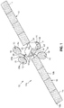
FIG. 1 is an illustration of a front perspective view of an exemplary spacecraft with various surfaces covered with an exemplary thermal control tape of the disclosure; -
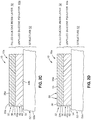
FIG. 2A is an illustration of an exploded cross-sectional view of an exemplary thermal control tape system that includes an exemplary thermal control tape of the disclosure; -
FIG. 2B is an illustration of an assembled cross-sectional view of the thermal control tape system and thermal control tape ofFIG. 2A ; -
FIG. 2C is an illustration of a cross-sectional view of the exemplary thermal control tape of the thermal control tape system ofFIG. 2B , applied to a structure; -
FIG. 2D is an illustration of a cross-sectional view of the thermal control tape ofFIG. 2C , having a plurality of perforations, and applied to the structure; -
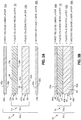
FIG. 3A is an illustration an exploded cross-sectional view of another exemplary thermal control tape system that includes another exemplary thermal control tape of the disclosure; -
FIG. 3B is an illustration of an assembled cross-sectional view of the thermal control tape system and thermal control tape ofFIG. 3A ; -
FIG. 3C is an illustration of a cross-sectional view of the exemplary thermal control tape of the thermal control tape system ofFIG. 3B , applied to a structure; -
FIG. 3D is an illustration of a cross-sectional view of the thermal control tape ofFIG. 3C , having a plurality of perforations, and applied to the structure; -
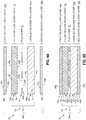
FIG. 4A is an illustration an exploded cross-sectional view of yet another exemplary thermal control tape system that includes yet another exemplary thermal control tape of the disclosure; -
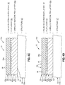
FIG. 4B is an illustration of an assembled cross-sectional view of the thermal control tape system and thermal control tape ofFIG. 4A ; -
FIG. 4C is an illustration of a cross-sectional view of the exemplary thermal control tape of the thermal control tape system ofFIG. 4B , applied to a structure; -
FIG. 4D is an illustration of a cross-sectional view of the thermal control tape ofFIG. 4C , having a plurality of perforations, and applied to the structure; -
FIG. 5A is an illustration an exploded cross-sectional view of yet another exemplary thermal control tape system that includes yet another exemplary thermal control tape of the disclosure; -
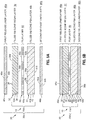
FIG. 5B is an illustration of an assembled cross-sectional view of the thermal control tape system and thermal control tape ofFIG. 5A ; -
FIG. 5C is an illustration of a cross-sectional view of the exemplary thermal control tape of the thermal control tape system ofFIG. 5B , applied to a structure; -
FIG. 5D is an illustration of a cross-sectional view of the thermal control tape ofFIG. 5C , having a plurality of perforations, and applied to the structure; -
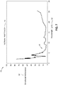
FIG. 6 is an illustration of a solar absorptance graph; -
FIG. 7 is an illustration of a normal emittance graph; -
FIG. 8 is an illustration of a functional block diagram showing exemplary versions of a thermal control tape system and a thermal control tape of the disclosure; -
FIG. 9 is an illustration of a flowchart showing an exemplary method of using a thermal control tape to provide thermal control of a spacecraft structure according to the disclosure; -
FIG. 10 is an illustration of a flow diagram of an exemplary spacecraft manufacturing and service method; and -
FIG. 11 is an illustration of an exemplary block diagram of a spacecraft. - Each figure shown in this disclosure shows a variation of an aspect of the aspects presented, and only differences will be discussed in detail.
- Disclosed versions or aspects will now be described more fully hereinafter with reference to the accompanying drawings, in which some, but not all of the disclosed aspects are shown. Indeed, several different versions or aspects may be provided and should not be construed as limited to the versions or aspects set forth herein. Rather, these versions or aspects are provided so that this disclosure will be thorough and fully convey the scope of the disclosure to those skilled in the art.
- Now referring to the Figures,
FIG. 1 is an illustration of a front perspective view of anexemplary spacecraft vehicle 12, such as in the form asatellite 12a, with one ormore surfaces 54 covered with an exemplarythermal control tape 10 of the disclosure. As shown inFIG. 1 , thespacecraft 12, such as in the form ofsatellite 12a, comprisessolar arrays 14. Each solar array 14 (seeFIG. 1 ) has afirst side 16a (seeFIG. 1 ) and asecond side 16b (seeFIG. 1 ). As shown inFIG. 1 , thesecond side 16b of eachsolar array 14 is coated or covered with thethermal control tape 10, as disclosed herein, and thefirst side 16a of eachsolar array 14 is not coated or covered with thethermal control tape 10. As further shown inFIG. 1 , thespacecraft 12, such as in the form ofsatellite 12a, comprises fourantennas 18. Each antenna 18 (seeFIG. 1 ) has afirst reflector side 20a (seeFIG. 1 ) and a secondnon-reflector side 20b (seeFIG. 1 ). As shown inFIG. 1 , thefirst reflector side 20a of eachantenna 18 is coated or covered with thethermal control tape 10, as disclosed herein, and the secondnon-reflector side 20b is not coated or covered with thethermal control tape 10. - As further shown in
FIG. 1 , thespacecraft 12, such as in the form ofsatellite 12a, comprises aradiator 22, one ormore struts 24, one ormore brackets 26, and one ormore fittings 28. One or more surfaces 54 (seeFIGS. 1 ,8 ) of the radiator 22 (seeFIG. 1 ), the one or more struts 24 (seeFIG. 1 ), the one or more brackets 26 (seeFIG. 1 ), and the one or more fittings 28 (seeFIG. 1 ) are coated or covered with thethermal control tape 10. - As used herein, "spacecraft" may include, but is not limited to, a
satellite 12a (seeFIGS. 1 ,8 ), anunmanned spacecraft 12b (seeFIG. 8 ), amanned spacecraft 12c (seeFIG. 8 ), arocket 12d (seeFIG. 8 ), are-entry vehicle 12e (seeFIG. 8 ), a reusable launch vehicle (RLV) 12f (seeFIG. 8 ), or another suitable spacecraft vehicle or object that travels through space. As used herein, "re-entry vehicles" may include, but are not limited to, satellites, rockets, manned and unmanned spacecraft and capsules, ballistic missile payloads, or other parts of a spacecraft configured to return from space through Earth's atmosphere and configured to withstand very high temperatures and very high speeds or velocities through Earth's atmosphere, and configured to protect crew members and/or instruments and equipment on the vehicle. As used herein, "reusable launch vehicle (RLV)" means a vehicle that is launched into space more than once, or is capable of launching a payload into space more than once. - In one version of the disclosure, there is provided the thermal control tape 10 (see
FIGS. 2A-5D ) for providing thermal control 11 (seeFIG. 8 ) of a structure 52 (seeFIG. 8 ), such as in the form of aspacecraft structure 52a (seeFIG. 8 ), to which thethermal control tape 10 is applied. - Now referring to
FIGS. 2A-2D , an exemplarythermal control tape 10 that may be part of an exemplary thermal control tape system 30 (seeFIGS. 2A-2B ) is provided.FIG. 2A is an illustration of an exploded cross-sectional view of the exemplary thermalcontrol tape system 30, such as in the form of thermalcontrol tape system 30a, that includes the exemplarythermal control tape 10, such as in the form ofthermal control tape 10a, of the disclosure.FIG. 2B is an illustration of an assembled cross-sectional view of the thermalcontrol tape system 30, such as in the form of thermalcontrol tape system 30a, ofFIG. 2A , with thethermal control tape 10, such as in the form ofthermal control tape 10a.FIG. 2C is an illustration of a cross-sectional view of the exemplarythermal control tape 10, such as in the form ofthermal control tape 10a, of the thermalcontrol tape system 30, ofFIG. 2B , applied to astructure 52, such as aspacecraft structure 52a.FIG. 2D is an illustration of a cross-sectional view of thethermal control tape 10, such as in the form ofthermal control tape 10a, ofFIG. 2C , having a plurality ofperforations 56, or openings, and applied to thestructure 52. - As shown in
FIGS. 2A-2D , the thermalcontrol tape system 30, such as in the form of thermalcontrol tape system 30a, comprises thethermal control tape 10, such as in the form ofthermal control tape 10a. The thermal control tape 10 (seeFIGS. 2A-2D ), such as in the form ofthermal control tape 10a (seeFIGS. 2A-2D ), comprises a filled silicone resin layer 32 (seeFIGS. 2A-2D ) having afirst side 38a (seeFIGS. 2A ,2C, 2D ) and asecond side 38b (seeFIG. 2A ). - The filled silicone resin layer 32 (see
FIGS. 2A-2D ) may comprise an unperforated filledsilicone resin layer 32a (seeFIGS. 2A-2C ), or may comprise a perforated filledsilicone resin layer 32b (seeFIG. 2D ). As shown inFIGS. 2A-2D , the filledsilicone resin layer 32 comprises asilicone resin material 34 filled with a whiteinorganic filler material 36. The silicone resin material 34 (seeFIGS. 2A-2D ) and the white inorganic filler material 36 (seeFIGS. 2A-2D ) are preferably present in a ratio of from 1:3 parts by weight to 1:4 parts by weight of the total weight of the filledsilicone resin layer 32. - The silicone resin material 34 (see
FIGS. 2A-2D ) may comprise a siliconepolymeric resin material 34a (seeFIG. 8 ) or another suitablesilicone resin material 34. The white inorganic filler material 36 (seeFIGS. 2A-2D ) of the filledsilicone resin layer 32 preferably comprises doped zincoxide pigment particles 36a (seeFIG. 8 ) formed from zinc oxide pigment particles 37 (seeFIG. 8 ) doped with a dopant element 39 (seeFIG. 8 ). As shown inFIG. 8 , which is discussed in more detail below, the dopant element 39 may consist of one or more of,aluminum 39a, gallium 39b,indium 39c,boron 39d,zinc 39e,tin 39f,hydrogen 39g, or another suitable dopant element 39. An exemplary method of preparing the whiteinorganic filler material 36 is disclosed inU.S. Patent No. 5,094,693 , which is herein incorporated by reference in its entirety. An exemplary method of preparing the filledsilicone resin layer 32 is disclosed inU.S. Patent No. 5,770,269 , which is herein incorporated by reference in its entirety. - The filled silicone resin layer 32 (see
FIGS. 2A-2D ) preferably has a thickness in a range of from about 2 mil (0.002 inch) to about 5 mil (0.005 inch). The thicker the filledsilicone resin layer 32 is, the more reflective it may be, and the lower a solar absorptance 71 (seeFIGS. 6 ,8 ) it may have. The filled silicone resin layer 32 (seeFIGS. 2A-2D ), with the white inorganic filler material 36 (seeFIGS. 2A-2D ), preferably has a solar absorptance 71 (seeFIGS. 6 ,8 ) that is low and preferably has a thermal emittance 84 (seeFIG. 8 ) that is high. - As shown in
FIGS. 2A-2D , thethermal control tape 10, such as in the form ofthermal control tape 10a, further comprises a silicone pressure sensitive adhesive (PSA)layer 40 having afirst side 44a (seeFIG. 2A ) and asecond side 44b (seeFIG. 2A ). Thefirst side 44a (seeFIG. 2A ) of the silicone PSA layer 40 (seeFIG. 2A ) is configured for attachment to, and is attached to, thesecond side 38b (seeFIG. 2A ) of the filled silicone resin layer 32 (seeFIG. 2A ). Preferably, the silicone PSA layer 40 (seeFIGS. 2A-2D ) comprises a silicone pressure sensitive adhesive (PSA) 42 (seeFIGS. 2A-2D ), or another suitable pressure sensitive adhesive (PSA). Thesilicone PSA layer 40 preferably has a superior adhesion over a wider temperature range, as compared to acrylic adhesives or rubber adhesives. In addition, thesilicone PSA layer 40 may be superior in terms of radiation degradation, as compared to other types of adhesives. - The silicone PSA layer 40 (see
FIGS. 2A-2D ) preferably has a thickness in a range of from about 2 mil (0.002 inch) to about 5 mil (0.005 inch), and more preferably, has a thickness of about 4 mil (0.004 inch). The thickness of thesilicone PSA layer 40 may be determined by its robustness, in terms of adhesion, in a space environment. - In one version of the
thermal control tape 10, shown inFIGS. 2A-2D andFIGS. 4A-4D , thesilicone PSA layer 40 comprises an unfilled silicone pressure sensitive adhesive (PSA)layer 40a. In another version of thethermal control tape 10, shown inFIGS. 3A-3D andFIGS. 5A-5D , and discussed in further detail below, thesilicone PSA layer 40 comprises a filled silicone pressure sensitive adhesive (PSA)layer 40b. - As shown in
FIGS. 2A-2B , the thermalcontrol tape system 30, such as in the form of thermalcontrol tape system 30a, further comprises a firstrelease liner layer 46a having afirst side 48a and asecond side 48b (seeFIG. 2A ). Thesecond side 48b of the firstrelease liner layer 46a is preferably removably attached to thefirst side 38a of the filledsilicone resin layer 32. - As shown in
FIGS. 2A-2B , the thermalcontrol tape system 30, such as in the form of thermalcontrol tape system 30a, further comprises a secondrelease liner layer 46b having afirst side 50a (seeFIG. 2A ) and asecond side 50b. Thefirst side 50a of the secondrelease liner layer 46b is preferably removably attached to thesecond side 44b of thesilicone PSA layer 40. - The first
release liner layer 46a (seeFIGS. 2A-2B ) and the secondrelease liner layer 46b (seeFIGS. 2A-2B ) may each comprise a fluoropolymer film, for example, a polyvinyl fluoride (PVF) film, or another suitable polymeric material. Preferably, the firstrelease liner layer 46a (seeFIGS. 2A-2B ) and the secondrelease liner layer 46b (seeFIGS. 2A-2B ) do not include a plasticizer in order to avoid degrading the whiteness of the white inorganic filler material 36 (seeFIGS. 2A-2B ) of the filled silicone resin layer 32 (seeFIGS. 2A-2B ). - The first
release liner layer 46a (seeFIGS. 2A-2B ) preferably has a thickness in a range of from about 1 mil (0.001 inch) to about 4 mil (0.004 inch), and more preferably, has a thickness in a range of from about 1 mil (0.001 inch) to about 2 mil (0.002 inch). The secondrelease liner layer 46b (seeFIGS. 2A-2B ) preferably has a thickness in a range of from about 3 mil (0.004 inch) to about 4 mil (0.004 inch), and more preferably, has a thickness of 4 mil (0.004 inch). The secondrelease liner layer 46b is preferably thicker than the firstrelease liner layer 46a because thesilicone PSA layer 40 tends to be sticky, and the thicker the secondrelease liner layer 46b adjacent thesilicone PSA layer 40 is, the easier it may be to remove the secondrelease liner layer 46b from thesilicone PSA layer 40. - As shown in
FIGS. 2C-2D , the filledsilicone resin layer 32 and the unfilledsilicone PSA layer 40a form thethermal control tape 10, such as in the form ofthermal control tape 10a, with thesecond side 44b (seeFIG. 2C ) of the unfilledsilicone PSA layer 40a configured for attachment to at least onesurface 54 of thestructure 52, such as thespacecraft structure 52a, of the spacecraft 12 (seeFIGS. 1 ,8 ), to provide thermal control 11 (seeFIG. 8 ) of thespacecraft structure 52a, by radiating heat 66 (seeFIG. 8 ) away from thespacecraft structure 52a. - As shown in
FIG. 2D , the filledsilicone resin layer 32 of thethermal control tape 10, such as in the form ofthermal control tape 10a, applied to thestructure 52, has a plurality ofperforations 56, or openings, to form the perforated filledsilicone resin layer 32b. The perforations 56 (seeFIG. 2D ), or openings, create a perforated surface 55 (seeFIG. 2D ) that may provide an escape or exit for any outgassing in a space environment. In addition, the perforated surface 55 (seeFIG. 2D ) may provide an escape or exit for any air during application of the thermal control tape 10 (seeFIG. 2D ) to the structure 52 (seeFIG. 2D ). - Now referring to
FIGS. 3A-3D , another exemplarythermal control tape 10 that may be part of another exemplary thermal control tape system 30 (seeFIGS. 3A-3B ) is provided.FIG. 3A is an illustration an exploded cross-sectional view of another exemplary thermalcontrol tape system 30, such as in the form of thermalcontrol tape system 30b, that includes another exemplarythermal control tape 10, such as in the form ofthermal control tape 10b, of the disclosure.FIG. 3B is an illustration of an assembled cross-sectional view of the thermalcontrol tape system 30, such as in the form of thermalcontrol tape system 30b, ofFIG. 3A , with thethermal control tape 10, such as in the form ofthermal control tape 10b.FIG. 3C is an illustration of a cross-sectional view of the exemplarythermal control tape 10, such as in the form ofthermal control tape 10b, of the thermalcontrol tape system 30, ofFIG. 3B , applied to thestructure 52, such as thespacecraft structure 52aFIG. 3D is an illustration of a cross-sectional view of thethermal control tape 10, such as in the form ofthermal control tape 10b, ofFIG. 3C , having the plurality ofperforations 56, or openings, and applied to thestructure 52. - In this version of the thermal
control tape system 30, such as in the form of thermalcontrol tape system 30b, shown inFIGS. 3A-3D , thesilicone PSA layer 40 comprises a filledsilicone PSA layer 40b, instead of an unfilledsilicone PSA layer 40a (seeFIGS. 2A-2D ). - As shown in
FIGS. 3A-3D , thethermal control tape 10, such as in the form ofthermal control tape 10b, of the thermalcontrol tape system 30, such as in the form of thermalcontrol tape system 30b, comprises the filledsilicone resin layer 32 having thefirst side 38a (seeFIGS. 3A ,3C, 3D ) and thesecond side 38b (seeFIG. 3A ). As discussed above, the filled silicone resin layer 32 (seeFIGS. 3A-3D ) may comprise the unperforated filledsilicone resin layer 32a (seeFIGS. 3A-3C ), or may comprise the perforated filledsilicone resin layer 32b (seeFIG. 3D ). As shown inFIGS. 3A-3D , the filledsilicone resin layer 32 comprises thesilicone resin material 34 filled with the whiteinorganic filler material 36. The silicone resin material 34 (seeFIGS. 3A-3D ) may comprise the siliconepolymeric resin material 34a (seeFIG. 8 ), or another suitablesilicone resin material 34, and the white inorganic filler material 36 (seeFIGS. 3A-3D ) is the same as discussed above with respect toFIGS. 2A-2D . The filled silicone resin layer 32 (seeFIGS. 3A-3D ) preferably has a thickness in a range of from about 2 mil (0.002 inch) to about 5 mil (0.005 inch). - As shown in
FIGS. 3A-3D , thethermal control tape 10, such as in the form ofthermal control tape 10b, further comprises the silicone pressure sensitive adhesive (PSA)layer 40 having thefirst side 44a (seeFIG. 3A ) and thesecond side 44b (seeFIG. 3A ). Thefirst side 44a (seeFIG. 3A ) of the silicone PSA layer 40 (seeFIG. 3A ) is configured for attachment to, and is attached to, thesecond side 38b (seeFIG. 3A ) of the filled silicone resin layer 32 (seeFIG. 3A ). Preferably, the silicone PSA layer 40 (seeFIGS. 3A-3D ) comprises the silicone pressure sensitive adhesive (PSA) 42 (seeFIGS. 3A-3D ), or another suitable pressure sensitive adhesive (PSA). As discussed above, the silicone PSA layer 40 (seeFIGS. 3A-3D ) preferably has a thickness in a range of from about 2 mil (0.002 inch) to about 5 mil (0.005 inch), and more preferably, has a thickness of about 4 mil (0.004 inch). - In this version shown in
FIGS. 3A-3D , thesilicone PSA layer 40 comprises the filled silicone pressure sensitive adhesive (PSA)layer 40b. Preferably, thesilicone PSA layer 40 is the filledsilicone PSA layer 40b. As shown inFIGS. 3A-3D , thesilicone PSA layer 40, such as in the form of filledsilicone PSA layer 40b, comprises an electrostatic dissipative (ESD)filler material 58. The ESD filler material 58 (seeFIGS. 3A-3D ) may comprise one of, ametallic filler material 58a (seeFIG. 8 ), acarbon filler material 58b (seeFIG. 8 ), or another suitableESD filler material 58. Themetallic filler material 58a (seeFIG. 8 ) may comprise nickel particles, copper particles, glass spheres coated with nickel, glass spheres coated with copper, or another suitablemetallic filler material 58a. Preferably, theESD filler material 58 is thecarbon filler material 58b (seeFIG. 8 ). - As shown in
FIGS. 3A-3B , the thermalcontrol tape system 30, such as in the form of thermalcontrol tape system 30b, further comprises the firstrelease liner layer 46a having thefirst side 48a and thesecond side 48b (seeFIG. 3A ), where thesecond side 48b of the firstrelease liner layer 46a is preferably removably attached to thefirst side 38a of the filledsilicone resin layer 32. As shown inFIGS. 3A-3B , the thermalcontrol tape system 30, such as in the form of thermalcontrol tape system 30b, further comprises the secondrelease liner layer 46b having thefirst side 50a (seeFIG. 3A ) and thesecond side 50b, where thefirst side 50a of the secondrelease liner layer 46b is preferably removably attached to thesecond side 44b of thesilicone PSA layer 40. The thicknesses and preferred materials of the firstrelease liner layer 46a (seeFIGS. 3A-3B ) and the secondrelease liner layer 46b (seeFIGS. 3A-3B ) are the same as discussed above with respect toFIGS. 2A-2B . - As shown in
FIGS. 3C-3D , the filledsilicone resin layer 32 and the filledsilicone PSA layer 40b form thethermal control tape 10, such as in the form ofthermal control tape 10b, with thesecond side 44b (seeFIG. 3A ) of the filledsilicone PSA layer 40b configured for attachment to at least onesurface 54 of thestructure 52, such as thespacecraft structure 52a, of the spacecraft 12 (seeFIGS. 1 ,8 ), to provide thermal control 11 (seeFIG. 8 ) of thespacecraft structure 52a, by radiating heat 66 (seeFIG. 8 ) away from thespacecraft structure 52a. - As shown in
FIG. 3D , the filledsilicone resin layer 32 of thethermal control tape 10, such as in the form ofthermal control tape 10b, applied to thestructure 52, has the plurality ofperforations 56, or openings, to form the perforated filledsilicone resin layer 32b. The perforations 56 (seeFIG. 3D ), or openings, create the perforated surface 55 (seeFIG. 3D ) that may provide an escape or exit for any outgassing in a space environment, or may provide an escape or exit for any air during application of the thermal control tape 10 (seeFIG. 3D ) to the structure 52 (seeFIG. 3D ). - Now referring to
FIGS. 4A-4D , another exemplarythermal control tape 10 that may be part of another exemplary thermal control tape system 30 (seeFIGS. 4A-4B ) is provided.FIG. 4A is an illustration an exploded cross-sectional view of yet another exemplary thermalcontrol tape system 30, such as in the form of thermalcontrol tape system 30c, that includes another exemplarythermal control tape 10, such as in the form ofthermal control tape 10c, of the disclosure.FIG. 4B is an illustration of an assembled cross-sectional view of the thermalcontrol tape system 30, such as in the form of thermalcontrol tape system 30c,ofFIG. 4A , with thethermal control tape 10, such as in the form ofthermal control tape 10c.FIG. 4C is an illustration of a cross-sectional view of the exemplarythermal control tape 10, such as in the form ofthermal control tape 10c, of the thermalcontrol tape system 30, ofFIG. 4B , applied to thestructure 52, such as thespacecraft structure 52aFIG. 4D is an illustration of a cross-sectional view of thethermal control tape 10, such as in the form ofthermal control tape 10c, ofFIG. 4C , having the plurality ofperforations 56, or openings, and applied to thestructure 52. - In this version of the thermal
control tape system 30, such as in the form of thermalcontrol tape system 30c, shown inFIGS. 4A-4D , thethermal control tape 10, such as in the form ofthermal control tape 10c, further comprises afilm layer 60 added between the filledsilicone resin layer 32 and thesilicone PSA layer 40, such as in the form of unfilledsilicone PSA layer 40a. In the version shown inFIGS. 4A-4D , thefilm layer 60 comprises anon-conductive film layer 60a. In another version shown inFIGS. 5A-5D , thefilm layer 60 comprises aconductive film layer 60b. - The
non-conductive film layer 60a (seeFIGS. 4A-4D ,8 ) preferably comprises an electrically insulatingpolyimide film 60c (seeFIG. 8 ), or another suitable non-conductive polyimide or polymer film. The film layer 60 (seeFIGS. 4A-4D ), such as in the form ofnon-conductive film layer 60a (seeFIGS. 4A-4D ), preferably has a thickness in a range of from about 1 mil (0.001 inch) to about 3 mil (0.003 inch), and more preferably, has a thickness of about 1 mil (0.001 inch). - As shown in
FIG. 4A , thefilm layer 60 has afirst side 62a and asecond side 62b. When assembled, thefirst side 62a (seeFIG. 4A ) of the film layer 60 (seeFIG. 4A ) is adjacent thesecond side 38b (seeFIG. 4A ) of the filledsilicone resin layer 32, and thesecond side 62b (seeFIG. 4A ) of the film layer 60 (seeFIG. 4A ) is adjacent thefirst side 44a (seeFIG. 4A ) of thesilicone PSA layer 40, such as the unfilledsilicone PSA layer 40a (seeFIG. 4A ). If thenon-conductive film layer 60a (seeFIGS. 4A-4D ) is added to thethermal control tape 10, such as in the form ofthermal control tape 10c, the unfilledsilicone PSA layer 40a is preferably used. - The addition of the
non-conductive film layer 60a (seeFIGS. 4A-4D ,8 ) to the thermal control tape 10 (seeFIGS. 4A-4D ) preferably improves tape handling stability. Thus, the thermal control tape 10 (seeFIGS. 4A-4D ), such as in the form ofthermal control tape 10c (seeFIGS. 4A-4D ), may provide an improved tape handling stability 92 (seeFIG. 8 ). - As shown in
FIGS. 4A-4D , thethermal control tape 10, such as in the form ofthermal control tape 10c, of the thermalcontrol tape system 30, such as in the form of thermalcontrol tape system 30c, comprises the filledsilicone resin layer 32 having thefirst side 38a (seeFIGS. 4A ,4C, 4D ) and thesecond side 38b (seeFIG. 4A ). As discussed above, the filled silicone resin layer 32 (seeFIGS. 4A-4D ) may comprise the unperforated filledsilicone resin layer 32a (seeFIGS. 4A-4C ), or may comprise the perforated filledsilicone resin layer 32b (seeFIG. 4D ). - As shown in
FIGS. 4A-4D , the filledsilicone resin layer 32 comprises thesilicone resin material 34 filled with the whiteinorganic filler material 36. The silicone resin material 34 (seeFIGS. 4A-4D ) may comprise the siliconepolymeric resin material 34a (seeFIG. 8 ), or another suitablesilicone resin material 34, and the white inorganic filler material 36 (seeFIGS. 4A-4D ) is the same as discussed above with respect toFIGS. 2A-2D . The filled silicone resin layer 32 (seeFIGS. 4A-4D ) preferably has the thickness in a range of from about 2 mil (0.002 inch) to about 5 mil (0.005 inch). - As shown in
FIGS. 4A-4D , thethermal control tape 10, such as in the form ofthermal control tape 10c, further comprises the silicone pressure sensitive adhesive (PSA)layer 40, in the form of unfilled silicone pressure sensitive adhesive (PSA)layer 40a, having thefirst side 44a (seeFIG. 4A ) and thesecond side 44b (seeFIG. 4A ). Thefirst side 44a (seeFIG. 4A ) of the silicone PSA layer 40 (seeFIG. 4A ) is configured for attachment to, and is attached to, thesecond side 38b (seeFIG. 4A ) of the filled silicone resin layer 32 (seeFIG. 4A ). Preferably, the silicone PSA layer 40 (seeFIGS. 4A-4D ) comprises the silicone pressure sensitive adhesive (PSA) 42 (seeFIGS. 4A-4D ), or another suitable pressure sensitive adhesive (PSA). As discussed above, the silicone PSA layer 40 (seeFIGS. 4A-4D ) preferably has the thickness in a range of from about 2 mil (0.002 inch) to about 5 mil (0.005 inch), and more preferably, has a thickness of about 4 mil (0.004 inch). - As shown in
FIGS. 4A-4B , the thermalcontrol tape system 30, such as in the form of thermalcontrol tape system 30c, further comprises the firstrelease liner layer 46a having thefirst side 48a and thesecond side 48b (seeFIG. 4A ), where thesecond side 48b of the firstrelease liner layer 46a is preferably removably attached to thefirst side 38a of the filledsilicone resin layer 32. As shown inFIGS. 4A-4B , the thermalcontrol tape system 30, such as in the form of thermalcontrol tape system 30c, further comprises the secondrelease liner layer 46b having thefirst side 50a (seeFIG. 4A ) and thesecond side 50b, where thefirst side 50a of the secondrelease liner layer 46b is preferably removably attached to thesecond side 44b of thesilicone PSA layer 40. The thicknesses and preferred materials of the firstrelease liner layer 46a (seeFIGS. 4A-4B ) and the secondrelease liner layer 46b (seeFIGS. 4A-4B ) are the same as discussed above with respect toFIGS. 2A-2B . - As shown in
FIGS. 4C-4D , the filledsilicone resin layer 32 and the unfilledsilicone PSA layer 40a form thethermal control tape 10, such as in the form ofthermal control tape 10c, with thesecond side 44b (seeFIG. 4A ) of the filledsilicone PSA layer 40b configured for attachment to at least onesurface 54 of thestructure 52, such as thespacecraft structure 52a, of the spacecraft 12 (seeFIGS. 1 ,8 ), to provide thermal control 11 (seeFIG. 8 ) of thespacecraft structure 52a, by radiating heat 66 (seeFIG. 8 ) away from thespacecraft structure 52a. - As shown in
FIG. 4D , the filledsilicone resin layer 32 of thethermal control tape 10, such as in the form ofthermal control tape 10c, applied to thestructure 52, has the plurality ofperforations 56, or openings, to form the perforated filledsilicone resin layer 32b. The perforations 56 (seeFIG. 4D ), or openings, create the perforated surface 55 (seeFIG. 4D ) that may provide an escape or exit for any outgassing in a space environment, or may provide an escape or exit for any air during application of the thermal control tape 10 (seeFIG. 4D ) to the structure 52 (seeFIG. 4D ). - Now referring to
FIGS. 5A-5D , another exemplarythermal control tape 10 that may be part of another exemplary thermal control tape system 30 (seeFIGS. 5A-5B ) is provided.FIG. 5A is an illustration an exploded cross-sectional view of yet another exemplary thermalcontrol tape system 30, such as in the form of thermalcontrol tape system 30d, that includes another exemplarythermal control tape 10, such as in the form ofthermal control tape 10d, of the disclosure.FIG. 5B is an illustration of an assembled cross-sectional view of the thermalcontrol tape system 30, such as in the form of thermalcontrol tape system 30d,ofFIG. 5A , with thethermal control tape 10, such as in the form ofthermal control tape 10d.FIG. 5C is an illustration of a cross-sectional view of the exemplarythermal control tape 10, such as in the form ofthermal control tape 10d, of the thermalcontrol tape system 30, ofFIG. 5B , applied to thestructure 52, such as thespacecraft structure 52aFIG. 5D is an illustration of a cross-sectional view of thethermal control tape 10, such as in the form ofthermal control tape 10d, ofFIG. 5C , having the plurality ofperforations 56, or openings, and applied to thestructure 52. - In this version of the thermal
control tape system 30, such as in the form of thermalcontrol tape system 30d, shown inFIGS. 5A-5D , thethermal control tape 10, such as in the form ofthermal control tape 10d, further comprises thefilm layer 60 added between the filledsilicone resin layer 32 and thesilicone PSA layer 40, such as in the form of filledsilicone PSA layer 40b. - In this version shown in
FIGS. 5A-5D , thefilm layer 60 comprises theconductive film layer 60b. Theconductive film layer 60b (seeFIGS. 5A-5D ,8 ) preferably comprises an electricallyconductive polyimide film 60d (seeFIG. 8 ), an electrically conductive carbon-filledpolyimide film 60e (seeFIG. 8 ), or another suitable conductive polyimide or polymer film. Preferably, theconductive film layer 60b remains stable across a wide range of temperatures, for example, from -269 degrees Celsius to +400 degrees Celsius (-452 degrees Fahrenheit to +752 degrees Fahrenheit). The film layer 60 (seeFIGS. 4A-4D ), such as in the form ofconductive film layer 60b (seeFIGS. 5A-5D ), preferably has a thickness in a range of from about 1 mil (0.001 inch) to about 3 mil (0.003 inch), and more preferably, has a thickness of about 1 mil (0.001 inch). - As shown in
FIG. 5A , thefilm layer 60 has thefirst side 62a and thesecond side 62b. When assembled, thefirst side 62a (seeFIG. 5A ) of the film layer 60 (seeFIG. 5A ) is adjacent thesecond side 38b (seeFIG. 5A ) of the filledsilicone resin layer 32, and thesecond side 62b (seeFIG. 5A ) of the film layer 60 (seeFIG. 5A ) is adjacent thefirst side 44a (seeFIG. 5A ) of thesilicone PSA layer 40, such as the filledsilicone PSA layer 40b (seeFIG. 5A ). If theconductive film layer 60b (seeFIGS. 5A-5D ) is added to the thermal control tape 10 (seeFIGS. 5A-5D ), such as in the form ofthermal control tape 10d (seeFIGS. 5A-5D , the filledsilicone PSA layer 40b (seeFIGS. 5A-5D ) filled with the ESD filler material 58 (seeFIGS. 5A-5D ), such as themetallic filler material 58a (seeFIG. 8 ) or thecarbon filler material 58b (seeFIG. 8 ), is preferably used. - The addition of the
conductive film layer 60b (seeFIGS. 5A-5D ,8 ) to the thermal control tape 10 (seeFIGS. 5A-5D ) may add greater electrical stability for electrostatic dissipation and may improve tape handling stability. Thus, the thermal control tape 10 (seeFIGS. 5A-5D ), such as in the form ofthermal control tape 10d (seeFIGS. 5A-5D ), may provide an improved electrical stability 90 (seeFIG. 8 ) and an improved tape handling stability 92 (seeFIG. 8 ). - As shown in
FIGS. 5A-5D , thethermal control tape 10, such as in the form ofthermal control tape 10d, of the thermalcontrol tape system 30, such as in the form of thermalcontrol tape system 30d, comprises the filledsilicone resin layer 32 having thefirst side 38a (seeFIGS. 5A ,5C, 5D ) and thesecond side 38b (seeFIG. 5A ). - As discussed above, the filled silicone resin layer 32 (see
FIGS. 5A-5D ) may comprise the unperforated filledsilicone resin layer 32a (seeFIGS. 5A-5C ), or may comprise the perforated filledsilicone resin layer 32b (seeFIG. 5D ). As shown inFIGS. 5A-5D , the filledsilicone resin layer 32 comprises thesilicone resin material 34 filled with the whiteinorganic filler material 36. - As shown in
FIGS. 5A-5D , the filledsilicone resin layer 32 comprises thesilicone resin material 34 filled with the whiteinorganic filler material 36. The silicone resin material 34 (seeFIGS. 5A-5D ) may comprise the siliconepolymeric resin material 34a (seeFIG. 8 ), or another suitablesilicone resin material 34, and the white inorganic filler material 36 (seeFIGS. 5A-5D ) is the same as discussed above with respect toFIGS. 2A-2D . The filled silicone resin layer 32 (seeFIGS. 5A-5D ) preferably has the thickness in a range of from about 2 mil (0.002 inch) to about 5 mil (0.005 inch). - As shown in
FIGS. 5A-5D , thethermal control tape 10, such as in the form ofthermal control tape 10d, further comprises thesilicone PSA layer 40, such as in the form of filledsilicone PSA layer 40b, having thefirst side 44a (seeFIG. 5A ) and thesecond side 44b (seeFIG. 5A ). Thefirst side 44a (seeFIG. 5A ) of the silicone PSA layer 40 (seeFIG. 5A ) is configured for attachment to, and is attached to, thesecond side 38b (seeFIG. 5A ) of the filled silicone resin layer 32 (seeFIG. 5A ). Preferably, the silicone PSA layer 40 (seeFIGS. 5A-5D ) comprises the silicone pressure sensitive adhesive (PSA) 42 (seeFIGS. 5A-5D ), or another suitable pressure sensitive adhesive (PSA). As discussed above, the silicone PSA layer 40 (seeFIGS. 5A-5D ) preferably has the thickness in a range of from about 2 mil (0.002 inch) to about 5 mil (0.005 inch), and more preferably, has a thickness of about 4 mil (0.004 inch). - As shown in
FIGS. 5A-5B , the thermalcontrol tape system 30, such as in the form of thermalcontrol tape system 30d, further comprises the firstrelease liner layer 46a having thefirst side 48a and thesecond side 48b (seeFIG. 5A ), where thesecond side 48b of the firstrelease liner layer 46a is preferably removably attached to thefirst side 38a of the filledsilicone resin layer 32. As shown inFIGS. 5A-5B , the thermalcontrol tape system 30, such as in the form of thermalcontrol tape system 30d, further comprises the secondrelease liner layer 46b having thefirst side 50a (seeFIG. 5A ) and thesecond side 50b, where thefirst side 50a of the secondrelease liner layer 46b is preferably removably attached to thesecond side 44b of thesilicone PSA layer 40. The thicknesses and preferred materials of the firstrelease liner layer 46a (seeFIGS. 5A-5B ) and the secondrelease liner layer 46b (seeFIGS. 5A-5B ) are the same as discussed above with respect toFIGS. 2A-2B . - Now referring to
FIG. 6, FIG. 6 is an illustration of asolar absorptance graph 70 for testing a solar absorptance (SA) 71 on a thermal control surface 64 (seeFIG. 8 ), for example, a white thermal control surface, such as the filled silicone resin layer 32 (seeFIGS. 2A-5D ) filled with the white inorganic filler material 36 (seeFIGS. 2A-5D ) of exemplary aspects of the thermal control tape 10 (seeFIGS. 2A-5D ) of the disclosure. As used herein, "solar absorptance" means a measure of the ability or effectiveness of a surface of a material in absorbing radiant energy, and is a ratio of total absorbed radiant energy to incident radiant energy measured as a unitless factor between 0 and 1. - To obtain the solar absorptance 71 (see
FIG. 6 ) of a surface or material, a percent (%)total reflectance 72, as a function of wavelength (nm - nanometer) 74, is measured, from which thesolar absorptance 71 is then calculated.FIG. 6 shows asolar absorptance plot 76. An average solar absorptance obtained from thesolar absorptance plot 76 was 0.2027. Preferably, the thermal control tape 10 (seeFIGS. 2A-5D ) disclosed herein has a solar absorptance (SA) 71 in a range of from 0.16 to 0.30. The filled silicone resin layer 32 (seeFIGS. 2A-5D ) functioning as a thermal control layer 64 (seeFIG. 8 ) preferably has asolar absorptance 71 that is low and a reflectance that is high. - Now referring to
FIG. 7, FIG. 7 is an illustration of anormal emittance graph 78 for testing a normal emittance 79 (or emittance or thermal emittance) on the thermal control surface 64 (seeFIG. 8 ), for example, the white thermal control surface, such as the filled silicone resin layer 32 (seeFIGS. 2A-5D ) filled with the white inorganic filler material 36 (seeFIGS. 2A-5D ) of exemplary aspects of the thermal control tape 10 (seeFIGS. 2A-5D ) of the disclosure. As used herein, "normal emittance" or "emittance" or "thermal emittance" means a measure of the energy radiated by the surface of a body per second per unit area, and is a ratio of the radiant emittance of heat of a specific surface to that of a standard black body measured as a unitless factor between 0 and 1. - To obtain the normal emittance 79 (see
FIG. 7 ) of a surface or material, adirectional reflectance 80, as a function of wavelength (µm - micrometer) 82, is measured, from which thenormal emittance 79 is then calculated.FIG. 6 shows anormal emittance plot 84. An average normal emittance obtained from thenormal emittance plot 84 was 0.93. The normal emittance 79 (seeFIG. 7 ) is measured at ahigher wavelength 82 than the solar absorptance 71 (seeFIG. 6 ). Preferably, the thermal control tape 10 (seeFIGS. 2A-5D ) disclosed herein has a thermal emittance 84 (seeFIG. 8 ) greater than 0.88. More preferably, the thermal control tape 10 (seeFIGS. 2A-5D ) has a thermal emittance 84 (seeFIG. 8 ) in a range of from 0.88 to 0.96. - Now referring to
FIG. 8, FIG. 8 is an illustration of a functional block diagram showing exemplary aspects of the thermalcontrol tape system 30 and thethermal control tape 10 of the disclosure. As shown inFIG. 8 , and as discussed in detail above, the thermal control tape 10 (seeFIGS. 2A-5D ) is designed for use on one ormore surfaces 54 of thestructure 52, such as thespacecraft structure 52a, of thespacecraft 12. As further shown inFIG. 8 , thespacecraft 12 may comprise asatellite 12a, anunmanned spacecraft 12b, amanned spacecraft 12c, arocket 12d, are-entry vehicle 12e, a reusable launch vehicle 12f, or anothersuitable spacecraft 12. Preferably, the surface 54 (seeFIG. 8 ) is aprepared surface 54a (seeFIG. 8 ) and athermal control surface 54b (seeFIG. 8 ). In certain versions, thesurface 54 may comprise a perforated surface 55 (seeFIGS. 2D ,3D ,4D ,5D ,8 ). - As further shown in
FIG. 8 , the thermalcontrol tape system 30 comprises the firstrelease liner layer 46a and the secondrelease liner layer 46b, discussed in detail above. As further shown inFIG. 8 , the thermalcontrol tape system 30 comprises thethermal control tape 10 for providingthermal control 11 of one ormore surfaces 54 of thestructure 52, such as thespacecraft structure 52a. The thermal control tape 10 (seeFIG. 8 ) comprises the filled silicone resin layer 32 (seeFIG. 8 ) in the form of the unperforated filledsilicone resin layer 32a (seeFIG. 8 ), or in the form of the perforated filledsilicone resin layer 32b (seeFIG. 8 ) having the plurality of perforations 56 (seeFIG. 8 ). - As shown in
FIG. 8 , the filledsilicone resin layer 32 comprises thesilicone resin material 34, such as in the form of siliconepolymeric resin material 34a, filled with the whiteinorganic filler material 36 comprising zincoxide pigment particles 37 doped with the dopant element 39. As further shown inFIG. 8 , the dopant element 39 consists of one of,aluminum 39a, gallium 39b,indium 39c, boron 39,zinc 39e,tin 39f,hydrogen 39g, or another suitable dopant element 39, to form doped zincoxide pigment particles 36a. - As shown in
FIG. 8 , thethermal control tape 10 further comprises the silicone pressure sensitive adhesive (PSA)layer 40 preferably made ofsilicone PSA 42, and coupled to the filledsilicone resin layer 32, where thesilicone PSA layer 40 may be in the form of the unfilledsilicone PSA layer 40a, or the filledsilicone PSA layer 40b. The silicone PSA layer 40 (seeFIG. 8 ), such as the filledsilicone PSA layer 40b (seeFIG. 8 ) preferably further comprises the electrostatic dissipative (ESD) filler material 58 (seeFIG. 8 ) comprising one of, themetallic filler material 58a (seeFIG. 8 ), thecarbon filler material 58b (seeFIG. 8 ), or another suitableESD filler material 58. The filledsilicone PSA layer 40b (seeFIG. 8 ) creates an electrostatic dissipative system 59 (seeFIG. 8 ). - In some versions, the thermal control tape 10 (see
FIG. 8 ) may optionally comprise the film layer 60 (seeFIG. 8 ) attached between the filled silicone resin layer 32 (seeFIG. 8 ) and the silicone PSA layer 40 (seeFIG. 8 ). As shown inFIG. 8 , in one version, thefilm layer 60 comprises thenon-conductive film layer 60a comprising the electrically insulatingpolyimide film 60c, or another suitable non-conductive polyimide or polymer. As further shown inFIG. 8 , in another version, thefilm layer 60 comprises theconductive film layer 60b comprising one of the electricallyconductive polyimide film 60d, the electrically conductive carbon-filledpolyimide film 60e, or another suitable conductive polyimide or polymer.
The thermal control tape 10 (seeFIG. 8 ) is configured for attachment to at least one surface 54 (seeFIG. 8 ) of the structure 52 (seeFIG. 8 ), such as thespacecraft structure 52a (seeFIG. 8 ), of the spacecraft 12 (seeFIGS. 1 ,8 ), to provide thermal control 11 (seeFIG. 8 ) of thespacecraft structure 52a, by radiating heat 66 (seeFIG. 8 ) away from thespacecraft structure 52a. The filled silicone resin layer 32 (seeFIG. 8 ) functions as a thermal control layer 64 (seeFIG. 8 ). The thermal control tape 10 (seeFIG. 8 ) functions as a thermallyemissive tape 86a (seeFIG. 8 ) comprising a cured thermallyemissive paint 86b (seeFIG. 8 ) adhered to a silicone PSA layer 40 (seeFIG. 8 ), where the thermal control tape 10 (seeFIG. 8 ) has auniform thickness 88 with improved quality (seeFIG. 8 ), an improvedelectrical stability 90, and an improved tape handling stability 92 (seeFIG. 8 ).
The thermal control tape 10 (seeFIG. 8 ) preferably meets the optical properties 68 (seeFIG. 8 ) of solar absorptance 71 (seeFIG. 8 ) being low (e.g., 0.18 to 0.30), and thermal emittance 84 (seeFIG. 8 ) being high (e.g., greater than 0.9). In the application of the thermal control tape 10 (seeFIG. 8 ), a robotic assembly 96 (seeFIG. 8 ) using a plurality of robot parameters 97 (seeFIG. 8 ) may preferably be used to control the thickness precisely and to optimize a uniform thickness 88 (seeFIG. 8 ) of thethermal control tape 10. Various robot parameters 97 (seeFIG. 8 ) may include, but are not limited to, positioning the robotic assembly 96 (seeFIG. 8 ) ninety (90) degrees to the surface 54 (seeFIG. 8 ) to be applied with thethermal control tape 10, using an optimum spraying angle 94 (seeFIG. 8 ) of six (6) +/- 0.25 inches spray nozzle to the structure 52 (seeFIG. 8 ), spraying four (4) inches beyond the edges of the structure 52 (seeFIG. 8 ), having a flow rate of two hundred (200) cc/min (cubic centimeters per minute), having a head speed of three hundred (300) mm/sec (millimeters per second), having a rastering index of 37.5 mm (millimeters), and othersuitable robot parameters 97. Preferably, the application using therobotic assembly 96 is performed at a temperature of about seventy-five (75) +/- 10 degrees Fahrenheit.
As further shown inFIG. 8 , thethermal control tape 10 may be formed with a thermalcontrol tape processing 98, including avacuum bag processing 98a, or other suitable processing techniques. The layers of the thermal control tape 10 (seeFIG. 8 ), such as the filled silicone resin layer 32 (seeFIG. 8 ), the silicone PSA layer 40 (seeFIG. 8 ), and optionally, the film layer 60 (seeFIG. 8 ), may be compressed together using thevacuum bag processing 98a (seeFIG. 8 ) or other suitable processing techniques.
In one exemplary thermalcontrol tape processing 98, the filled silicone resin layer 32 (seeFIG. 8 ) may be applied, such as spray applied, to the firstrelease liner layer 46a (seeFIG. 8 ). The silicone PSA layer 40 (seeFIG. 8 ) having the secondrelease liner layer 46b (seeFIG. 8 ) applied to thesilicone PSA layer 40 may then be applied on top of the filled silicone resin layer 32 (seeFIG. 8 ). The filledsilicone resin layer 32 with the firstrelease liner layer 46a and thesilicone PSA layer 40 with the secondrelease liner layer 46b may then be vacuum sealed with thevacuum bag processing 98a or another suitable sealing process, to compress the filledsilicone resin layer 32 and thesilicone PSA layer 40 together. When thethermal control tape 10 is processed and ready for application to one or more surfaces 54 (seeFIG. 8 ) of the structure 52 (seeFIG. 8 ), the secondrelease liner layer 46b may be removed from thesilicone PSA layer 40 and thesilicone PSA layer 40 applied to thesurface 54, and the firstrelease liner layer 46a may be removed from the filledsilicone resin layer 32.
Now referring toFIG. 9, FIG. 9 is an illustration of an exemplary flowchart showing amethod 100 of using a thermal control tape 10 (seeFIGS. 2A-5D ) to provide thermal control 11 (seeFIG. 8 ) of a structure 52 (seeFIGS. 2C ,3C ,4C ,5C ,8 ), such as aspacecraft structure 52a (seeFIGS. 2C ,3C ,4C ,5C ,8 ), to which the thermal control tape 10 (seeFIGS. 2A-5D ) is applied, according to an aspect of the disclosure. As shown inFIG. 9 , themethod 100 comprisesstep 102 of assembling a thermal control tape system 30 (seeFIG. 8 ). The thermal control tape system 30 (seeFIG. 8 ) comprises a thermal control tape 10 (seeFIGS. 2A-3D ,8 ), as discussed in detail above.
As further discussed above, the thermal control tape 10 (seeFIGS. 2A-5D ) comprises the filled silicone resin layer 32 (seeFIGS. 2A-5D ) having thefirst side 38a (seeFIG. 2A ) and thesecond side 38b (seeFIG. 2A ). The filled silicone resin layer 32 (seeFIGS. 2A-5D ) comprises the silicone resin material 34 (seeFIGS. 2A-5D ) filled with the white inorganic filler material 36 (seeFIGS. 2A-5D ). The thermal control tape 10 (seeFIGS. 2A-5D ) comprises the silicone pressure sensitive adhesive (PSA) layer 40 (seeFIGS. 2A-5D ) having thefirst side 44a (seeFIG. 2A ) and thesecond side 44b (seeFIG. 2A ). Thefirst side 44a of thesilicone PSA layer 40 is attached to the second side 28b of the filledsilicone resin layer 32.
As further discussed above, the thermal control tape system 30 (seeFIGS. 2A ,3A ,4A ,5A ) further comprises the firstrelease liner layer 46a (seeFIGS. 2A ,3A ,4A ,5A ) removably attached to thefirst side 38a of the filledsilicone resin layer 32. The thermal control tape system 30 (seeFIGS. 2A ,3A ,4A ,5A ) further comprises the secondrelease liner layer 46b (seeFIGS. 2A ,3A ,4A ,5A ) removably attached to thesecond side 44b of thesilicone PSA layer 40.
The step 102 (seeFIG. 9 ) of assembling the thermal control tape system 30 (seeFIGS. 3A ,5A ) may further comprise adding to the silicone PSA layer 40 (seeFIGS. 3A ,5A ) of the thermal control tape 10 (seeFIGS. 3A ,5A ), an electrostatic dissipative (ESD) filler material 58 (seeFIGS. 3A ,5A ) comprising one of, ametallic filler material 58a (seeFIG. 8 ), acarbon filler material 58b (seeFIG. 8 ), or another suitableESD filler material 58.
The step 102 (seeFIG. 9 ) of assembling the thermal control tape system 30 (seeFIGS. 4A-5D ) may further comprise optionally adding a film layer 60 (seeFIGS. 4A-5D ) between the filled silicone resin layer 32 (seeFIGS. 4A-5D ) and the silicone PSA layer 40 (seeFIGS. 4A-5D ). As discussed above, thefilm layer 60 may comprise anon-conductive film layer 60a (seeFIGS. 4A-4D ), or may comprise aconductive film layer 60b (seeFIGS. 5A-5D ).
The step 102 (seeFIG. 9 ) of assembling the thermal control tape system 30 (seeFIGS. 2A-5D ) may further comprise forming the white inorganic filler material 36 (seeFIGS. 2A-5D ) of the filled silicone resin layer 32 (seeFIGS. 2A-5D ) of the thermal control tape 10 (seeFIGS. 2A-5D ) comprising doped zincoxide pigment particles 36a (seeFIG. 8 ) formed from zinc oxide pigment particles 37 (seeFIG. 8 ) doped with the dopant element 39 (seeFIG. 8 ). As shown inFIG. 8 , the dopant element 39 may consist ofaluminum 39a, gallium 39b,indium 39c,boron 39d,zinc 39e,tin 39f,hydrogen 39g, or another suitable dopant element 39.
As shown inFIG. 9 , themethod 100 further comprises step 104 of preparing at least one surface 54 (seeFIGS. 2C ,3C ,4C ,5C ,8 ) of the structure 52 (seeFIGS. 2C ,3C ,4C ,5C ,8 ), such as thespacecraft structure 52a (seeFIG. 8 ), to obtain at least oneprepared surface 54a (seeFIG. 8 ), for application of the thermal control tape 10 (seeFIGS. 2C ,3C ,4C ,5C ,8 ).
As shown inFIG. 9 , themethod 100 further comprises step 106 of removing the secondrelease liner layer 46b (seeFIGS. 2A ,3A ,4A ,5A ) from thesecond side 44b (seeFIGS. 2A ,3A ,4A ,5A ) of the silicone PSA layer 40 (seeFIGS. 2A ,3A ,4A ,5A ).
As shown inFIG. 9 , themethod 100 further comprises step 108 of applying thesecond side 44b (seeFIGS. 2A ,3A ,4A ,5A ) of the silicone PSA layer 40 (seeFIGS. 2A ,3A ,4A ,5A ) to the at least oneprepared surface 54a (seeFIG. 8 ) of thespacecraft structure 52a (seeFIG. 8 ).
As shown inFIG. 9 , themethod 100 further comprises step 110 of removing the firstrelease liner layer 46a (seeFIGS. 2A ,3A ,4A ,5A ) from thefirst side 38a (seeFIGS. 2A ,3A ,4A ,5A ) of the filled silicone resin layer 32 (seeFIGS. 2A ,3A ,4A ,5A ).
Themethod 100 may be partially or fully performed on a manual basis or on an automated basis. If the method 100 (seeFIG. 9 ) is performed on an automated basis, at least thestep 104 of preparing the at least one surface 54 (seeFIGS. 1 ,2C ,3C ,4C ,5C ), thestep 106 of removing the secondrelease liner layer 46b (seeFIGS. 2A ,3A ,4A ,5A ), thestep 108 of applying thesecond side 44b (seeFIGS. 2A ,3A ,4A ,5A ) of the silicone PSA layer 40 (seeFIGS. 2A ,3A ,4A ,5A ), and thestep 110 of removing the firstrelease liner layer 46a, are preferably performed using a robotic assembly 96 (seeFIG. 8 ).
FIG. 10 is an illustration of a flow diagram of an exemplary spacecraft manufacturing andservice method 200.FIG. 11 is an illustration of an exemplary block diagram of aspacecraft 216. Referring toFIGS. 10-11 , aspects of the disclosure may be described in the context of the spacecraft manufacturing andservice method 200 as shown inFIG. 10 , and thespacecraft 216 as shown inFIG. 11 .
During pre-production, exemplary spacecraft manufacturing andservice method 200 may include specification anddesign 202 of thespacecraft 216 andmaterial procurement 204. During manufacturing, component andsubassembly manufacturing 206 andsystem integration 208 of thespacecraft 216 takes place. Thereafter, thespacecraft 216 may go through certification anddelivery 210 in order to be placed inservice 212. While inservice 212 by a customer, thespacecraft 216 may be scheduled for routine maintenance and service 214 (which may also include modification, reconfiguration, refurbishment, and other suitable services).
Each of the processes of the spacecraft manufacturing andservice method 200 may be performed or carried out by a system integrator, a third party, and/or an operator (e.g., a customer). For the purposes of this description, a system integrator may include, without limitation, any number of spacecraft manufacturers and major-system subcontractors. A third party may include, without limitation, any number of vendors, subcontractors, and suppliers. An operator may include an aerospace company, a leasing company, a military entity, a service organization, and other suitable operators.
As shown inFIG. 11 , thespacecraft 216 produced by the exemplary spacecraft manufacturing andservice method 200 may include aframe 218 with a plurality ofsystems 220 and an interior 222. Examples of the plurality ofsystems 220 may include one or more of apropulsion system 224 and anelectrical system 226. Any number of other systems may be included. Although an aerospace example is shown, the principles of the disclosure may be applied to other industries, such as the automotive industry.
Methods and systems embodied herein may be employed during any one or more of the stages of the spacecraft manufacturing andservice method 200. For example, components or subassemblies corresponding to component andsubassembly manufacturing 206 may be fabricated or manufactured in a manner similar to components or subassemblies produced while thespacecraft 216 is inservice 212. Also, one or more apparatus aspects, method aspects, or a combination thereof, may be utilized during component andsubassembly manufacturing 206 andsystem integration 208, for example, by substantially expediting assembly of or reducing the cost of thespacecraft 216. Similarly, one or more of apparatus aspects, method aspects, or a combination thereof, may be utilized while thespacecraft 216 is inservice 212, for example and without limitation, to maintenance andservice 214.
Disclosed aspects of the thermal control tape 10 (seeFIGS. 2A-5D ,8 ), the thermal control tape system 30 (seeFIGS. 2A-2B ,3A-3B ,4A-4B ,5A-5B ,8 ), and the method 100 (seeFIG. 9 ) provide a novel solution for producing athermal control surface 54b (seeFIG. 8 ) that radiates heat 66 (seeFIG. 8 ) from spacecraft 12 (seeFIG. 8 ) by using a thermallyemissive tape 86a (seeFIG. 8 ) comprised of a filled silicone resin layer 32 (seeFIG. 8 ) and a silicone PSA layer 40 (seeFIG. 8 ), rather than coating structures such as radiators and other components with thermal paint alone. All the processes associated with painting, including masking, priming, painting, demasking, and cleanup are eliminated and replaced with a peel and stick thermal control and thermallyemissive tape 86a (seeFIG. 8 ). Moreover, because these processes associated with painting are eliminated, the need for paint facilities, such as a paint booth, is also eliminated, the need for trained and certified painters is eliminated, the environmental impact and safety concerns of painting are eliminated, the 7-14 day paint curing time is eliminated, and the overall processing and cycle time are reduced. Thus, the simplicity of the thermal control tape 10 (seeFIGS. 2A-5D ,8 ), the thermal control tape system 30 (seeFIGS. 2A-2B ,3A-3B ,4A-4B ,5A-5B ,8 ), and the method 100 (seeFIG. 9 ) allow for cost reduction and reduced cycle time by eliminating the painting operations, and allow for replacement of paint when economical and practical.
Further, the thermal control layer 64 (seeFIG. 8 ) may be applied late in the spacecraft/hardware integration or during a final spacecraft integration, as opposed to having to paint early due to the paint process, which may increase the risk that the white thermal control layer may be scuffed or damaged along the process. Moreover, there is no need to transfer hardware or sensitive electronics to a paint facility. Thus, the thermal control tape 10 (seeFIGS. 2A-5D ,8 ), the thermal control tape system 30 (seeFIGS. 2A-2B ,3A-3B ,4A-4B ,5A-5B ,8 ), and the method 100 (seeFIG. 9 ) allow for faster hardware integration due to the point of integration application of the white PSA (e.g., no need to transfer to a paint facility). - In addition, disclosed aspects of the thermal control tape 10 (see
FIGS. 2A-5D ,8 ), the thermal control tape system 30 (seeFIGS. 2A-2B ,3A-3B ,4A-4B ,5A-5B ,8 ), and the method 100 (seeFIG. 9 ) provide optimized optical properties 68 (seeFIG. 8 ), such as a low solar absorptance 71 (seeFIG. 8 ) and a high thermal emittance 84 (seeFIG. 8 ). As compared to known thermal control tapes, such as known silver and aluminum foil tapes, thethermal emittance 84 of thethermal control tape 10 disclosed herein is much higher and the reflection is a desirable diffuse reflection as opposed to an undesirable specular reflection. Further, disclosed aspects of the thermal control tape 10 (seeFIGS. 2A-5D ,8 ) provide a thermal control layer 64 (seeFIG. 8 ) having a uniform thickness 88 (seeFIG. 8 ) and uniform coverage with no variability in the thickness or coverage of the filled silicone resin layer 32 (seeFIGS. 2A-5D ), and in turn, the thermal control tape 10 (seeFIGS. 2A-5D ). Moreover, disclosed aspects of the thermal control tape 10 (seeFIGS. 2A-5D ) diffuse reflectance, provide electrostatic charge dissipation, provide easy and simple touchup, if a piece of thethermal control tape 10 needs to be reapplied or fixed, eliminate a seven (7) day or longer curing time, provide improved adhesion over a wide temperature range and provide the ability to remain adhered to the substrate given the harsh space environment (i.e., large temperature deltas and radiation exposure), and provide survival against radiation damage.
Further, the disclosure comprises aspects according to the following clauses: - Clause 1. A thermal control tape for providing thermal control of a spacecraft structure, to which the thermal control tape is applied, the thermal control tape comprising:
- a filled silicone resin layer having a first side and a second side, the filled silicone resin layer comprising a silicone resin material filled with a white inorganic filler material; and
- a silicone pressure sensitive adhesive (PSA) layer having a first side and a second side, the first side of the silicone PSA layer attached to the second side of the filled silicone resin layer,
- wherein the filled silicone resin layer and the silicone PSA layer form the thermal control tape, with the second side of the silicone PSA layer configured for attachment to at least one surface of the spacecraft structure of a spacecraft, to provide thermal control of the spacecraft structure, by radiating heat away from the spacecraft structure.
- Clause 2. The thermal control tape of Clause 1 further comprising a first release liner layer removably attached to the first side of the filled silicone resin layer, and a second release liner layer removably attached to the second side of the silicone PSA layer.
- Clause 3. The thermal control tape of Clause 1-2 further comprising a film layer added between the filled silicone resin layer and the silicone PSA layer.
- Clause 4. The thermal control tape of Clause 3 wherein the film layer comprises a conductive film layer.
-
Clause 5. The thermal control tape of Clause 3 wherein the film layer comprises a non-conductive film layer. - Clause 6. The thermal control tape of Clause 1-5 wherein the white inorganic filler material comprises doped zinc oxide pigment particles formed from zinc oxide pigment particles doped with a dopant element comprising one of, aluminum, gallium, indium, boron, zinc, tin, and hydrogen.
- Clause 7. The thermal control tape of Clause 1-6 wherein the silicone PSA layer further comprises an electrostatic dissipative (ESD) filler material comprising one of, a metallic filler material, and a carbon filler material.
- Clause 8. The thermal control tape of Clause 1-7 wherein the thermal control tape has a solar absorptance (SA) in a range of 0.16 to 0.30.
- Clause 9. The thermal control tape of Clause 1-8 wherein the thermal control tape has a thermal emittance in a range of 0.88 to 0.96.
-
Clause 10. The thermal control tape of Clause 1-9 wherein the filled silicone resin layer has a plurality of perforations. -
Clause 11. A thermal control tape for providing thermal control of a spacecraft structure, the thermal control tape comprising:- a filled silicone resin layer having a first side and a second side, the filled silicone resin layer comprising a silicone resin material filled with a white inorganic filler material, wherein the silicone resin material and the white inorganic filler material are present in a ratio of from 1:3 parts by weight to 1:4 parts by weight, and wherein the white inorganic filler material comprises zinc oxide pigment particles doped with a dopant element comprising one of, aluminum, gallium, indium, boron, zinc, tin, and hydrogen, to form doped zinc oxide pigment particles; and
- a silicone pressure sensitive adhesive (PSA) layer having a first side and a second side, the first side of the silicone PSA layer attached to the second side of the filled silicone resin layer, and the second side of the silicone PSA layer configured for attachment to the at least one surface of the spacecraft structure, to provide thermal control of the spacecraft structure, by radiating heat away from the spacecraft structure.
-
Clause 12. The thermal control tape ofClause 11 further comprising a first release liner layer removably attached to the first side of the filled silicone resin layer, and a second release liner layer removably attached to the second side of the silicone PSA layer. - Clause 13. The thermal control tape of Clause 11-12 wherein the silicone PSA layer further comprises an electrostatic dissipative filler material comprising one of, a metallic filler material, and a carbon filler material.
-
Clause 14. The thermal control tape ofClause 12 further comprising a film layer attached between the filled silicone resin layer and the silicone PSA layer, the film layer comprising a conductive film layer comprising one of an electrically conductive polyimide film, and an electrically conductive carbon-filled polyimide film. -
Clause 15. The thermal control tape ofClause 11 further comprising a film layer attached between the filled silicone resin layer and the silicone PSA layer, the film layer comprising a non-conductive film layer comprising an electrically insulating polyimide film. - Clause 16. A method of using a thermal control tape to provide thermal control of a spacecraft structure, to which the thermal control tape is applied, the method comprising the steps of:
- assembling a thermal control tape system comprising:
a thermal control tape comprising:- a filled silicone resin layer having a first side and a second side, the filled silicone resin layer comprising a silicone resin material filled with a white inorganic filler material; and
- a silicone pressure sensitive adhesive (PSA) layer having a first side and a second side, the first side of the silicone PSA layer attached to the second side of the filled silicone resin layer;
- a first release liner layer removably attached to the first side of the filled silicone resin layer; and
- a second release liner layer removably attached to the second side of the silicone PSA layer;
- preparing at least one surface of the spacecraft structure, to obtain at least one prepared surface, for application of the thermal control tape;
- removing the second release liner layer from the second side of the silicone PSA layer;
- applying the second side of the silicone PSA layer to the at least one prepared surface of the spacecraft structure; and
- removing the first release liner layer from the first side of the filled silicone resin layer.
- assembling a thermal control tape system comprising:
- Clause 17. The method of Clause 16 wherein assembling the thermal control tape system further comprises adding to the silicone PSA layer of the thermal control tape, an electrostatic dissipative (ESD) filler material comprising one of, a metallic filler material, and a carbon filler material.
-
Clause 18. The method of Clause 17 wherein assembling the thermal control tape system further comprises adding a film layer between the filled silicone resin layer and the silicone PSA layer, the film layer comprising a conductive film layer. - Clause 19. The method of Clause 16 wherein assembling the thermal control tape system further comprises adding a film layer between the filled silicone resin layer and the silicone PSA layer, the film layer comprising a non-conductive film layer.
-
Clause 20. The method of Clause 16 wherein at least preparing the at least one surface, removing the second release liner layer, applying the second side of the silicone PSA layer, and removing the first release liner layer, are performed using a robotic assembly. - Many modifications and other aspects of the disclosure will come to mind to one skilled in the art to which this disclosure pertains having the benefit of the teachings presented in the foregoing descriptions and the associated drawings. The aspects described herein are meant to be illustrative and are not intended to be limiting or exhaustive. Although specific terms are employed herein, they are used in a generic and descriptive sense only and not for purposes of limitation.
Claims (15)
- A thermal control tape (10) for providing thermal control of a spacecraft structure (52a), to which the thermal control tape is applied, the thermal control tape comprising:a filled silicone resin layer (32) having a first side (38a) and a second side (38b), the filled silicone resin layer comprising a silicone resin material (34) filled with a white inorganic filler material (36); anda silicone pressure sensitive adhesive (PSA) layer (40) having a first side (44a) and a second side (44b), the first side of the silicone PSA layer attached to the second side of the filled silicone resin layer,wherein the filled silicone resin layer and the silicone PSA layer form the thermal control tape, with the second side of the silicone PSA layer configured for attachment to at least one surface (54) of the spacecraft structure of a spacecraft (12), to provide thermal control of the spacecraft structure, by radiating heat away from the spacecraft structure.
- The thermal control tape (10) of claim 1 further comprising a first release liner layer (46a) removably attached to the first side (38a) of the filled silicone resin layer (32), and a second release liner layer (46b) removably attached to the second side (44b) of the silicone PSA layer (40).
- The thermal control tape (10) of any of claims 1-2 further comprising a film layer (60) added between the filled silicone resin layer (32) and the silicone PSA layer (40).
- The thermal control tape (10) of claim 3 wherein the film layer (60) comprises a conductive film layer (60b).
- The thermal control tape (10) of claim 3 wherein the film layer (60) comprises a non-conductive film layer (60a).
- The thermal control tape (10) of any of claims 1-5 wherein the white inorganic filler material (36) comprises doped zinc oxide pigment particles (36a) formed from zinc oxide pigment particles (37) doped with a dopant element (39) comprising one of, aluminum, gallium, indium, boron, zinc, tin, and hydrogen.
- The thermal control tape (10) of any of claims 1-6 wherein the silicone PSA layer (40) further comprises an electrostatic dissipative (ESD) filler material (58) comprising one of, a metallic filler material (58a), and a carbon filler material (58b).
- The thermal control tape (10) of any of claims 1-7 wherein the thermal control tape has a solar absorptance (71) (SA) in a range of 0.16 to 0.30.
- The thermal control tape (10) of any of claims 1-8 wherein the thermal control tape has a thermal emittance (84) in a range of 0.88 to 0.96.
- The thermal control tape (10) of any of claims 1-9 wherein the filled silicone resin layer (32) has a plurality of perforations (56).
- A method (100) of using a thermal control tape (10) to provide thermal control of a spacecraft structure (52a), to which the thermal control tape is applied, the method comprising the steps of:assembling (102) a thermal control tape system (30) comprising:a thermal control tape comprising:a filled silicone resin layer (32) having a first side (38a) and a second side (38b), the filled silicone resin layer comprising a silicone resin material filled (34) with a white inorganic filler material (36); anda silicone pressure sensitive adhesive (PSA) layer (40) having a first side (44a) and a second side (44b), the first side of the silicone PSA layer attached to the second side of the filled silicone resin layer;a first release liner layer (46a) removably attached to the first side of the filled silicone resin layer; anda second release liner layer (46b) removably attached to the second side of the silicone PSA layer;preparing (104) at least one surface (54) of the spacecraft structure (52a), to obtain at least one prepared surface (54a), for application of the thermal control tape;removing (106) the second release liner layer from the second side of the silicone PSA layer;applying (108) the second side of the silicone PSA layer to the at least one prepared surface of the spacecraft structure; andremoving (110) the first release liner layer from the first side of the filled silicone resin layer.
- The method (100) of claim 11 wherein assembling (102) the thermal control tape system (30) further comprises adding to the silicone PSA layer (40) of the thermal control tape (10), an electrostatic dissipative (ESD) filler material (58) comprising one of, a metallic filler material (58a), and a carbon filler material (58b).
- The method (100) of any of claims 11-12 wherein assembling (102) the thermal control tape system (30) further comprises adding a film layer (60) between the filled silicone resin layer (32) and the silicone PSA layer (40), the film layer comprising a conductive film layer (60b).
- The method (100) of any of claims 11-13 wherein assembling (102) the thermal control tape system (30) further comprises adding a film layer (60) between the filled silicone resin layer (32) and the silicone PSA layer (40), the film layer comprising a non-conductive film layer (60a).
- The method (100) of any of claims 11-14 wherein at least preparing (104) the at least one surface (54), removing the second release liner layer (46b), applying the second side (44b) of the silicone PSA layer (40), and removing the first release liner layer (46a), are performed using a robotic assembly (96).
Applications Claiming Priority (1)
| Application Number | Priority Date | Filing Date | Title |
|---|---|---|---|
| US15/821,462 US20190152626A1 (en) | 2017-11-22 | 2017-11-22 | Thermal control tape, system, and method for a spacecraft structure |
Publications (2)
| Publication Number | Publication Date |
|---|---|
| EP3489317A1 true EP3489317A1 (en) | 2019-05-29 |
| EP3489317B1 EP3489317B1 (en) | 2022-05-04 |
Family
ID=64331913
Family Applications (1)
| Application Number | Title | Priority Date | Filing Date |
|---|---|---|---|
| EP18206729.8A Active EP3489317B1 (en) | 2017-11-22 | 2018-11-16 | Thermal control tape, system, and method for a spacecraft structure |
Country Status (4)
| Country | Link |
|---|---|
| US (1) | US20190152626A1 (en) |
| EP (1) | EP3489317B1 (en) |
| JP (1) | JP7213062B2 (en) |
| CN (1) | CN109808919B (en) |
Families Citing this family (3)
| Publication number | Priority date | Publication date | Assignee | Title |
|---|---|---|---|---|
| CN111776253B (en) * | 2020-07-20 | 2022-03-22 | 北京卫星环境工程研究所 | Spacecraft propulsion membrane structure using space plasma and preparation method thereof |
| CN111893451B (en) * | 2020-08-13 | 2022-10-21 | 上海卫星工程研究所 | High-performance wave-transparent nano thermal control film for satellite, preparation method and application thereof |
| US12168530B2 (en) * | 2023-02-28 | 2024-12-17 | Lockheed Martin Corporation | Thermal control systems and methods for spacecraft |
Citations (5)
| Publication number | Priority date | Publication date | Assignee | Title |
|---|---|---|---|---|
| US5094693A (en) | 1990-02-20 | 1992-03-10 | International Lead Zinc Research Organization, Inc. | Doped zinc oxide-based pigment |
| US5770269A (en) | 1994-05-13 | 1998-06-23 | Hughes Aircraft Company | Thermal control coating |
| US6124378A (en) * | 1997-03-18 | 2000-09-26 | Hughes Electronics Corporation | (Zinc, cadmium, magnesium) aluminate-gallate-containing organic-binder paint and film articles |
| CN1916057A (en) * | 2005-08-17 | 2007-02-21 | 中科纳米技术工程中心有限公司 | Sunlight controlled transparent film in low radiation, prepartion method and application |
| EP2873993A1 (en) * | 2012-07-13 | 2015-05-20 | Konica Minolta, Inc. | Infrared-shielding film |
Family Cites Families (25)
| Publication number | Priority date | Publication date | Assignee | Title |
|---|---|---|---|---|
| US5427849A (en) * | 1990-02-28 | 1995-06-27 | Morgan Adhesive Company | Pressure sensitive adhesive tape with central release liner and its use on a jacket portion of insulation member |
| US5069969A (en) * | 1990-02-28 | 1991-12-03 | Morgan Adhesives Co. | Pressure sensitive adhesive tape with central release liner |
| US5215824A (en) * | 1990-12-05 | 1993-06-01 | General Electric Co. | RF-transparent spacecraft thermal control barrier |
| JP2934128B2 (en) * | 1993-09-27 | 1999-08-16 | 稲谷 芳文 | Thermal protection system structure and method of manufacturing the same |
| US5858624A (en) * | 1996-09-20 | 1999-01-12 | Minnesota Mining And Manufacturing Company | Method for assembling planarization and indium-tin-oxide layer on a liquid crystal display color filter with a transfer process |
| JP4140067B2 (en) * | 1997-04-08 | 2008-08-27 | 三菱電機株式会社 | Manufacturing method of composite material |
| JP3653016B2 (en) * | 2000-07-07 | 2005-05-25 | Nec東芝スペースシステム株式会社 | Thermal control apparatus and thermal control method |
| JP3732126B2 (en) * | 2001-08-06 | 2006-01-05 | 川崎重工業株式会社 | Thermal defense structure |
| US7629123B2 (en) * | 2003-07-03 | 2009-12-08 | University Of Medicine And Dentistry Of New Jersey | Compositions and methods for diagnosing autism |
| CA2575238C (en) * | 2004-08-11 | 2015-04-21 | Dow Corning Corporation | Photopolymerizable silicone materials forming semipermeable membranes for sensor applications |
| DE102004052022B4 (en) * | 2004-10-26 | 2008-10-30 | Uzin Tyro Ag | Self-adhesive film with air channels |
| US7632568B2 (en) | 2005-01-07 | 2009-12-15 | 3M Innovative Properties Company | Solar control multilayer film |
| CN101657522B (en) | 2007-04-13 | 2014-05-07 | 3M创新有限公司 | Antistatic optically clear pressure sensitive adhesive |
| PT2650210T (en) * | 2009-04-17 | 2018-05-10 | 3M Innovative Properties Co | Lightning protection sheet with patterned discriminator |
| FR2958653B1 (en) * | 2010-04-08 | 2013-11-29 | Centre Nat Etd Spatiales | ANTISTATIC WHITE COATING WITH SILYLATED BASE |
| CN102241950A (en) * | 2010-05-14 | 2011-11-16 | 3M创新有限公司 | Electromagnetic shielding adhesive tape |
| US11299619B2 (en) * | 2011-07-01 | 2022-04-12 | The Boeing Company | Composite structure having an inorganic coating adhered thereto and method of making same |
| US9620658B1 (en) * | 2012-03-13 | 2017-04-11 | Deployable Space Systems, Inc. | Integrated modular photovoltaic blanket assembly for space solar array |
| WO2014137801A1 (en) * | 2013-03-03 | 2014-09-12 | John Moore | Temporary adhesive with tunable adhesion force sufficient for processing thin solid materials |
| US9820367B2 (en) * | 2013-07-01 | 2017-11-14 | The Boeing Company | Apparatuses, methods and systems for passive counter-directed energy platform protection |
| JP6539429B2 (en) | 2013-08-28 | 2019-07-03 | 三菱重工業株式会社 | Flexible heat control material and propellant tank |
| WO2015029975A1 (en) * | 2013-08-28 | 2015-03-05 | 三菱重工業株式会社 | Flexible thermal-control material, and production method therefor |
| WO2015072794A1 (en) * | 2013-11-15 | 2015-05-21 | 주식회사 엘지화학 | Adhesive composition |
| KR20150071149A (en) * | 2013-12-18 | 2015-06-26 | (주)티디엘 | Thermal conductive sheet comprised electromagnetic interference shielding |
| CN203912428U (en) * | 2014-03-13 | 2014-10-29 | 厦门恒坤新材料科技股份有限公司 | Composite heat-conduction graphite flake |
-
2017
- 2017-11-22 US US15/821,462 patent/US20190152626A1/en not_active Abandoned
-
2018
- 2018-11-07 JP JP2018209339A patent/JP7213062B2/en active Active
- 2018-11-16 EP EP18206729.8A patent/EP3489317B1/en active Active
- 2018-11-21 CN CN201811388845.7A patent/CN109808919B/en active Active
Patent Citations (5)
| Publication number | Priority date | Publication date | Assignee | Title |
|---|---|---|---|---|
| US5094693A (en) | 1990-02-20 | 1992-03-10 | International Lead Zinc Research Organization, Inc. | Doped zinc oxide-based pigment |
| US5770269A (en) | 1994-05-13 | 1998-06-23 | Hughes Aircraft Company | Thermal control coating |
| US6124378A (en) * | 1997-03-18 | 2000-09-26 | Hughes Electronics Corporation | (Zinc, cadmium, magnesium) aluminate-gallate-containing organic-binder paint and film articles |
| CN1916057A (en) * | 2005-08-17 | 2007-02-21 | 中科纳米技术工程中心有限公司 | Sunlight controlled transparent film in low radiation, prepartion method and application |
| EP2873993A1 (en) * | 2012-07-13 | 2015-05-20 | Konica Minolta, Inc. | Infrared-shielding film |
Also Published As
| Publication number | Publication date |
|---|---|
| RU2018135649A3 (en) | 2021-12-14 |
| EP3489317B1 (en) | 2022-05-04 |
| RU2018135649A (en) | 2020-04-10 |
| CN109808919B (en) | 2023-09-26 |
| US20190152626A1 (en) | 2019-05-23 |
| JP7213062B2 (en) | 2023-01-26 |
| CN109808919A (en) | 2019-05-28 |
| JP2019147540A (en) | 2019-09-05 |
Similar Documents
| Publication | Publication Date | Title |
|---|---|---|
| EP3489317A1 (en) | Thermal control tape, system, and method for a spacecraft structure | |
| US20140299712A1 (en) | Thermal Barrier Coated RF Radomes | |
| US5283592A (en) | Antenna sunshield membrane | |
| US5589274A (en) | Thermal control coating | |
| CN112321868B (en) | Removal of surface films and primers from composite substrates by use of co-cured paint films | |
| US20090104396A1 (en) | Color pattern film for metal shell | |
| US10787575B2 (en) | Black molecular adsorber coating system | |
| US20180306530A1 (en) | Passively deployable thermal management devices, systems, and methods | |
| GB2545494A (en) | A structure formed from composite material | |
| RU2772059C2 (en) | Thermoregulating tape, system and method for spacecraft construction | |
| US11262489B1 (en) | Methods for increasing IR emittance of thin film second surface mirrored thermal control coatings | |
| US7834799B1 (en) | System and method for fabricating composite laminate structures with co-laminated radar absorbing material | |
| US9236660B2 (en) | Electromagnetic attenuating object and method of electromagnetic attenuation | |
| US4534998A (en) | Conductive coating process | |
| EP0780921B1 (en) | Sunshield film transparent to radio frequency energy and shielded articles | |
| CN103600829B (en) | A kind of Weather-proof stratospheric airship | |
| JP2004360904A (en) | Heat insulation material and formation method of heat insulation material | |
| CN103587676B (en) | A kind of High Altitude Airship | |
| CN103600830B (en) | A kind of Ultraviolet-resistanhigh-altitude high-altitude airship | |
| US20040178967A1 (en) | Painted broadcast-frequency reflective component | |
| CN103612436B (en) | A kind of Weather resistant high altitude airship | |
| CN103587673B (en) | A kind of Weather-proof near space airship | |
| CN103587672B (en) | A kind of stratospheric airship | |
| CN103587675B (en) | A kind of Ultraviolet-resistanstratosphere stratosphere airship | |
| EP3621787A1 (en) | Method of bonding a metal fitting to a polyurethane structure |
Legal Events
| Date | Code | Title | Description |
|---|---|---|---|
| PUAI | Public reference made under article 153(3) epc to a published international application that has entered the european phase |
Free format text: ORIGINAL CODE: 0009012 |
|
| STAA | Information on the status of an ep patent application or granted ep patent |
Free format text: STATUS: REQUEST FOR EXAMINATION WAS MADE |
|
| 17P | Request for examination filed |
Effective date: 20181116 |
|
| AK | Designated contracting states |
Kind code of ref document: A1 Designated state(s): AL AT BE BG CH CY CZ DE DK EE ES FI FR GB GR HR HU IE IS IT LI LT LU LV MC MK MT NL NO PL PT RO RS SE SI SK SM TR |
|
| AX | Request for extension of the european patent |
Extension state: BA ME |
|
| GRAP | Despatch of communication of intention to grant a patent |
Free format text: ORIGINAL CODE: EPIDOSNIGR1 |
|
| STAA | Information on the status of an ep patent application or granted ep patent |
Free format text: STATUS: GRANT OF PATENT IS INTENDED |
|
| GRAS | Grant fee paid |
Free format text: ORIGINAL CODE: EPIDOSNIGR3 |
|
| GRAA | (expected) grant |
Free format text: ORIGINAL CODE: 0009210 |
|
| STAA | Information on the status of an ep patent application or granted ep patent |
Free format text: STATUS: THE PATENT HAS BEEN GRANTED |
|
| INTG | Intention to grant announced |
Effective date: 20220307 |
|
| AK | Designated contracting states |
Kind code of ref document: B1 Designated state(s): AL AT BE BG CH CY CZ DE DK EE ES FI FR GB GR HR HU IE IS IT LI LT LU LV MC MK MT NL NO PL PT RO RS SE SI SK SM TR |
|
| REG | Reference to a national code |
Ref country code: GB Ref legal event code: FG4D |
|
| REG | Reference to a national code |
Ref country code: CH Ref legal event code: EP |
|
| REG | Reference to a national code |
Ref country code: AT Ref legal event code: REF Ref document number: 1489043 Country of ref document: AT Kind code of ref document: T Effective date: 20220515 |
|
| REG | Reference to a national code |
Ref country code: IE Ref legal event code: FG4D Ref country code: DE Ref legal event code: R096 Ref document number: 602018034841 Country of ref document: DE |
|
| REG | Reference to a national code |
Ref country code: LT Ref legal event code: MG9D |
|
| REG | Reference to a national code |
Ref country code: NL Ref legal event code: MP Effective date: 20220504 |
|
| REG | Reference to a national code |
Ref country code: AT Ref legal event code: MK05 Ref document number: 1489043 Country of ref document: AT Kind code of ref document: T Effective date: 20220504 |
|
| PG25 | Lapsed in a contracting state [announced via postgrant information from national office to epo] |
Ref country code: SE Free format text: LAPSE BECAUSE OF FAILURE TO SUBMIT A TRANSLATION OF THE DESCRIPTION OR TO PAY THE FEE WITHIN THE PRESCRIBED TIME-LIMIT Effective date: 20220504 Ref country code: PT Free format text: LAPSE BECAUSE OF FAILURE TO SUBMIT A TRANSLATION OF THE DESCRIPTION OR TO PAY THE FEE WITHIN THE PRESCRIBED TIME-LIMIT Effective date: 20220905 Ref country code: NO Free format text: LAPSE BECAUSE OF FAILURE TO SUBMIT A TRANSLATION OF THE DESCRIPTION OR TO PAY THE FEE WITHIN THE PRESCRIBED TIME-LIMIT Effective date: 20220804 Ref country code: NL Free format text: LAPSE BECAUSE OF FAILURE TO SUBMIT A TRANSLATION OF THE DESCRIPTION OR TO PAY THE FEE WITHIN THE PRESCRIBED TIME-LIMIT Effective date: 20220504 Ref country code: LT Free format text: LAPSE BECAUSE OF FAILURE TO SUBMIT A TRANSLATION OF THE DESCRIPTION OR TO PAY THE FEE WITHIN THE PRESCRIBED TIME-LIMIT Effective date: 20220504 Ref country code: HR Free format text: LAPSE BECAUSE OF FAILURE TO SUBMIT A TRANSLATION OF THE DESCRIPTION OR TO PAY THE FEE WITHIN THE PRESCRIBED TIME-LIMIT Effective date: 20220504 Ref country code: GR Free format text: LAPSE BECAUSE OF FAILURE TO SUBMIT A TRANSLATION OF THE DESCRIPTION OR TO PAY THE FEE WITHIN THE PRESCRIBED TIME-LIMIT Effective date: 20220805 Ref country code: FI Free format text: LAPSE BECAUSE OF FAILURE TO SUBMIT A TRANSLATION OF THE DESCRIPTION OR TO PAY THE FEE WITHIN THE PRESCRIBED TIME-LIMIT Effective date: 20220504 Ref country code: ES Free format text: LAPSE BECAUSE OF FAILURE TO SUBMIT A TRANSLATION OF THE DESCRIPTION OR TO PAY THE FEE WITHIN THE PRESCRIBED TIME-LIMIT Effective date: 20220504 Ref country code: BG Free format text: LAPSE BECAUSE OF FAILURE TO SUBMIT A TRANSLATION OF THE DESCRIPTION OR TO PAY THE FEE WITHIN THE PRESCRIBED TIME-LIMIT Effective date: 20220804 Ref country code: AT Free format text: LAPSE BECAUSE OF FAILURE TO SUBMIT A TRANSLATION OF THE DESCRIPTION OR TO PAY THE FEE WITHIN THE PRESCRIBED TIME-LIMIT Effective date: 20220504 |
|
| PG25 | Lapsed in a contracting state [announced via postgrant information from national office to epo] |
Ref country code: RS Free format text: LAPSE BECAUSE OF FAILURE TO SUBMIT A TRANSLATION OF THE DESCRIPTION OR TO PAY THE FEE WITHIN THE PRESCRIBED TIME-LIMIT Effective date: 20220504 Ref country code: PL Free format text: LAPSE BECAUSE OF FAILURE TO SUBMIT A TRANSLATION OF THE DESCRIPTION OR TO PAY THE FEE WITHIN THE PRESCRIBED TIME-LIMIT Effective date: 20220504 Ref country code: LV Free format text: LAPSE BECAUSE OF FAILURE TO SUBMIT A TRANSLATION OF THE DESCRIPTION OR TO PAY THE FEE WITHIN THE PRESCRIBED TIME-LIMIT Effective date: 20220504 Ref country code: IS Free format text: LAPSE BECAUSE OF FAILURE TO SUBMIT A TRANSLATION OF THE DESCRIPTION OR TO PAY THE FEE WITHIN THE PRESCRIBED TIME-LIMIT Effective date: 20220904 |
|
| PG25 | Lapsed in a contracting state [announced via postgrant information from national office to epo] |
Ref country code: SM Free format text: LAPSE BECAUSE OF FAILURE TO SUBMIT A TRANSLATION OF THE DESCRIPTION OR TO PAY THE FEE WITHIN THE PRESCRIBED TIME-LIMIT Effective date: 20220504 Ref country code: SK Free format text: LAPSE BECAUSE OF FAILURE TO SUBMIT A TRANSLATION OF THE DESCRIPTION OR TO PAY THE FEE WITHIN THE PRESCRIBED TIME-LIMIT Effective date: 20220504 Ref country code: RO Free format text: LAPSE BECAUSE OF FAILURE TO SUBMIT A TRANSLATION OF THE DESCRIPTION OR TO PAY THE FEE WITHIN THE PRESCRIBED TIME-LIMIT Effective date: 20220504 Ref country code: EE Free format text: LAPSE BECAUSE OF FAILURE TO SUBMIT A TRANSLATION OF THE DESCRIPTION OR TO PAY THE FEE WITHIN THE PRESCRIBED TIME-LIMIT Effective date: 20220504 Ref country code: DK Free format text: LAPSE BECAUSE OF FAILURE TO SUBMIT A TRANSLATION OF THE DESCRIPTION OR TO PAY THE FEE WITHIN THE PRESCRIBED TIME-LIMIT Effective date: 20220504 Ref country code: CZ Free format text: LAPSE BECAUSE OF FAILURE TO SUBMIT A TRANSLATION OF THE DESCRIPTION OR TO PAY THE FEE WITHIN THE PRESCRIBED TIME-LIMIT Effective date: 20220504 |
|
| REG | Reference to a national code |
Ref country code: DE Ref legal event code: R097 Ref document number: 602018034841 Country of ref document: DE |
|
| PLBE | No opposition filed within time limit |
Free format text: ORIGINAL CODE: 0009261 |
|
| STAA | Information on the status of an ep patent application or granted ep patent |
Free format text: STATUS: NO OPPOSITION FILED WITHIN TIME LIMIT |
|
| RAP4 | Party data changed (patent owner data changed or rights of a patent transferred) |
Owner name: THE BOEING COMPANY |
|
| PG25 | Lapsed in a contracting state [announced via postgrant information from national office to epo] |
Ref country code: AL Free format text: LAPSE BECAUSE OF FAILURE TO SUBMIT A TRANSLATION OF THE DESCRIPTION OR TO PAY THE FEE WITHIN THE PRESCRIBED TIME-LIMIT Effective date: 20220504 |
|
| 26N | No opposition filed |
Effective date: 20230207 |
|
| PG25 | Lapsed in a contracting state [announced via postgrant information from national office to epo] |
Ref country code: SI Free format text: LAPSE BECAUSE OF FAILURE TO SUBMIT A TRANSLATION OF THE DESCRIPTION OR TO PAY THE FEE WITHIN THE PRESCRIBED TIME-LIMIT Effective date: 20220504 |
|
| P01 | Opt-out of the competence of the unified patent court (upc) registered |
Effective date: 20230516 |
|
| PG25 | Lapsed in a contracting state [announced via postgrant information from national office to epo] |
Ref country code: MC Free format text: LAPSE BECAUSE OF FAILURE TO SUBMIT A TRANSLATION OF THE DESCRIPTION OR TO PAY THE FEE WITHIN THE PRESCRIBED TIME-LIMIT Effective date: 20220504 |
|
| REG | Reference to a national code |
Ref country code: CH Ref legal event code: PL |
|
| REG | Reference to a national code |
Ref country code: BE Ref legal event code: MM Effective date: 20221130 |
|
| PG25 | Lapsed in a contracting state [announced via postgrant information from national office to epo] |
Ref country code: LI Free format text: LAPSE BECAUSE OF NON-PAYMENT OF DUE FEES Effective date: 20221130 Ref country code: CH Free format text: LAPSE BECAUSE OF NON-PAYMENT OF DUE FEES Effective date: 20221130 |
|
| PG25 | Lapsed in a contracting state [announced via postgrant information from national office to epo] |
Ref country code: LU Free format text: LAPSE BECAUSE OF NON-PAYMENT OF DUE FEES Effective date: 20221116 |
|
| PG25 | Lapsed in a contracting state [announced via postgrant information from national office to epo] |
Ref country code: IE Free format text: LAPSE BECAUSE OF NON-PAYMENT OF DUE FEES Effective date: 20221116 |
|
| PG25 | Lapsed in a contracting state [announced via postgrant information from national office to epo] |
Ref country code: BE Free format text: LAPSE BECAUSE OF NON-PAYMENT OF DUE FEES Effective date: 20221130 |
|
| PG25 | Lapsed in a contracting state [announced via postgrant information from national office to epo] |
Ref country code: IT Free format text: LAPSE BECAUSE OF FAILURE TO SUBMIT A TRANSLATION OF THE DESCRIPTION OR TO PAY THE FEE WITHIN THE PRESCRIBED TIME-LIMIT Effective date: 20220504 |
|
| PG25 | Lapsed in a contracting state [announced via postgrant information from national office to epo] |
Ref country code: HU Free format text: LAPSE BECAUSE OF FAILURE TO SUBMIT A TRANSLATION OF THE DESCRIPTION OR TO PAY THE FEE WITHIN THE PRESCRIBED TIME-LIMIT; INVALID AB INITIO Effective date: 20181116 |
|
| PG25 | Lapsed in a contracting state [announced via postgrant information from national office to epo] |
Ref country code: CY Free format text: LAPSE BECAUSE OF FAILURE TO SUBMIT A TRANSLATION OF THE DESCRIPTION OR TO PAY THE FEE WITHIN THE PRESCRIBED TIME-LIMIT Effective date: 20220504 |
|
| PG25 | Lapsed in a contracting state [announced via postgrant information from national office to epo] |
Ref country code: MK Free format text: LAPSE BECAUSE OF FAILURE TO SUBMIT A TRANSLATION OF THE DESCRIPTION OR TO PAY THE FEE WITHIN THE PRESCRIBED TIME-LIMIT Effective date: 20220504 |
|
| PG25 | Lapsed in a contracting state [announced via postgrant information from national office to epo] |
Ref country code: MT Free format text: LAPSE BECAUSE OF FAILURE TO SUBMIT A TRANSLATION OF THE DESCRIPTION OR TO PAY THE FEE WITHIN THE PRESCRIBED TIME-LIMIT Effective date: 20220504 |
|
| PG25 | Lapsed in a contracting state [announced via postgrant information from national office to epo] |
Ref country code: BG Free format text: LAPSE BECAUSE OF FAILURE TO SUBMIT A TRANSLATION OF THE DESCRIPTION OR TO PAY THE FEE WITHIN THE PRESCRIBED TIME-LIMIT Effective date: 20220504 |
|
| PG25 | Lapsed in a contracting state [announced via postgrant information from national office to epo] |
Ref country code: BG Free format text: LAPSE BECAUSE OF FAILURE TO SUBMIT A TRANSLATION OF THE DESCRIPTION OR TO PAY THE FEE WITHIN THE PRESCRIBED TIME-LIMIT Effective date: 20220504 |
|
| PG25 | Lapsed in a contracting state [announced via postgrant information from national office to epo] |
Ref country code: TR Free format text: LAPSE BECAUSE OF FAILURE TO SUBMIT A TRANSLATION OF THE DESCRIPTION OR TO PAY THE FEE WITHIN THE PRESCRIBED TIME-LIMIT Effective date: 20220504 |
|
| PGFP | Annual fee paid to national office [announced via postgrant information from national office to epo] |
Ref country code: DE Payment date: 20251128 Year of fee payment: 8 |
|
| PGFP | Annual fee paid to national office [announced via postgrant information from national office to epo] |
Ref country code: GB Payment date: 20251127 Year of fee payment: 8 |
|
| PGFP | Annual fee paid to national office [announced via postgrant information from national office to epo] |
Ref country code: FR Payment date: 20251125 Year of fee payment: 8 |