EP3489185A1 - Cooling solution for hoisting machinery - Google Patents
Cooling solution for hoisting machinery Download PDFInfo
- Publication number
- EP3489185A1 EP3489185A1 EP17203477.9A EP17203477A EP3489185A1 EP 3489185 A1 EP3489185 A1 EP 3489185A1 EP 17203477 A EP17203477 A EP 17203477A EP 3489185 A1 EP3489185 A1 EP 3489185A1
- Authority
- EP
- European Patent Office
- Prior art keywords
- hoisting machinery
- stator
- evaporator
- frame
- expansion tank
- Prior art date
- Legal status (The legal status is an assumption and is not a legal conclusion. Google has not performed a legal analysis and makes no representation as to the accuracy of the status listed.)
- Granted
Links
Images


Classifications
-
- B—PERFORMING OPERATIONS; TRANSPORTING
- B66—HOISTING; LIFTING; HAULING
- B66B—ELEVATORS; ESCALATORS OR MOVING WALKWAYS
- B66B11/00—Main component parts of lifts in, or associated with, buildings or other structures
- B66B11/04—Driving gear ; Details thereof, e.g. seals
- B66B11/043—Driving gear ; Details thereof, e.g. seals actuated by rotating motor; Details, e.g. ventilation
Definitions
- the present invention refers to a hoisting machinery for an elevator having a cooling system in the form of a free flowing cooling system.
- Hoisting machineries for elevators are usually embodied as electric motors having a stator core with windings and a rotor with magnets.
- electric current When electric current is supplied to the windings, most of the electric energy is transferred into a force acting on the rotor's magnets for making the rotor rotate.
- a part of the electric energy is transferred by the windings into heat which heats the stator core and its surroundings.
- the generated heat acts on the material of not only the windings and the stator but also on that of isolators resulting in that these materials are prone to thermal aging such that the life span of the hoisting machinery is deteriorated.
- sufficient cooling of the electric motor is always important.
- a hoisting machinery for an elevator comprises a frame with a stator flange, a stator supported at the stator flange, stator windings arranged at the stator, and a cooling system having an evaporator part, a condenser part and an expansion tank, wherein a cooling medium can circulate through the cooling system.
- the evaporator part is arranged at the stator flange in a manner to allow the cooling medium to receive heat generated by the stator windings
- the condenser part is arranged at the frame in a manner to be in contact with ambient air
- the expansion tank is arranged at the frame in a manner to allow the condensed cooling medium to be collected.
- the evaporator part is an evaporator pipe which is arranged in a meandering shape at the stator flange. This allows the evaporator part to efficiently collect heat from the stator.
- the frame constitutes a part of a hoisting machinery housing and the evaporator part is arranged inside the hoisting machinery housing, and the condenser part and the expansion tank are arranged outside the hoisting machinery housing. This allows the heat collected in the evaporator part to be transferred to the outside of the hoisting machinery housing.
- the evaporator part exits the hoisting machinery housing at an upper portion of the hoisting machinery housing and is connected to the condenser part. This allows the vaporous cooling medium in the evaporator part to rise upward and to easily enter the condenser part where the vaporous cooling medium can condense to become liquid cooling medium.
- the expansion tank is arranged on a lower side of the hoisting machine housing and is connected to the evaporator part and the condenser part.
- the evaporator part is connected to a lower portion of the expansion tank and the condenser part is connected to an upper portion of the expansion tank. This assures that the liquefied cooling medium can enter the expansion tank by gravity and that the evaporator part is always in communication with the liquefied cooling medium.
- the hoisting machinery further comprises frame fixing means for fixing the frame to a guide rail for guiding an elevator car in a shaft.
- the condenser part is heat conductively connected to a guide rail for guiding an elevator car in a shaft. This allows to more effectively transfer the heat of vaporous cooling medium to the ambient air.
- the stator is part of an electric motor having an outer rotor.
- the electric motor is configured as a radial flux machinery.
- the electric motor has a rotor comprising a traction sheave which has a smaller diameter than a magnet mounting portion of the rotor for mounting rotor magnets.
- a hoisting machinery 1 is configured as an electric motor having a stator 4 and a rotor 6 being mounted to a machine frame 2.
- the machine frame 2 has a shell-like structure for partly covering the electric motor from one side thereof.
- the machine frame 2 has a vertical rail slot 16 allowing a guide rail 9 to pass the machine frame 2.
- the guide rail 9 is mounted to a not shown elevator shaft and is also used to guide an elevator car along the guide rail 9 during the up and down movement of the elevator car in the shaft.
- the machine frame 2 further comprises lower struts 24 and upper struts 25 on each of the left and right side and machinery brakes 26 are mounted vertically between the outer end portions of the struts 24, 25.
- rope openings 17 are formed in the machine frame 2 below the lower struts 24 so as to allow ropes 23 to pass from inside the hoisting machinery 1 to the outside thereof.
- the ropes 23 are driven by the hoisting machinery 1 so as to make the elevator car move up or down in the shaft.
- the rope openings 17 also allow ambient air to flow towards the electric motor for cooling purpose.
- lateral vent openings 18 are formed between the lower struts 24 and the upper struts 25 so as to allow ambient air to flow towards the electric motor for cooling purpose.
- the lateral vent openings 18 are formed between respective lower struts 24 and upper struts 25 of the machinery frame 2.
- upper vent openings 19 are formed above the upper struts 25 so as to allow ambient air to flow towards the electric motor for cooling purpose.
- the upper vent openings 19 are formed to lie in a substantially horizontal plane.
- the machine frame 2 comprises a stator flange 3 which protrudes from the inner side of a central portion 29 of the machine frame 2 (see Fig. 1 ) in a direction away from the guide rail 9 and is formed integrally with the machine frame 2.
- the stator flange 3 has the shape of continuous ring.
- Fig. 2 also shows that the machine frame 2 has an upper projection which projects from the machine frame 2 to the upper side, and a lower projection which projects form the machine frame 2 to the lower side.
- An upper fixing means 14 is fixed to the upper projection and to the guide rail 9, and a lower fixing means 15 is fixed to the lower projection and the guide rail 9. As a result, the machine frame 2 is fixed to the guide rail 9.
- stator flange 3 has stator flange openings 27 which correspond to the rope openings 17 with respect to the circumferential direction of the machine frame 2.
- stator flange openings 27 each have a dimension in the axial direction corresponding to a later described rope groove portion 8 of the rotor 6, in which grooves for accommodating the ropes 23 are provided.
- the rope groove portion 8 corresponds to the traction sheave according to the invention.
- a ring-shaped stator 4 is mounted to the distal end (left end in Fig. 2 ) of the stator flange 3 at a radial outside position thereof and is fit onto a portion of the stator flange 3 which has a reduced dimension in the radial direction to form a seat against which the stator 4 is pressed in the axial direction by means of bolts.
- the stator 4 comprises radially extending protrusions about which stator windings 5 are wound in a manner to general a radial magnetic flux.
- the stator windings 5 are wound to have longer components extending in the axial direction of the hoisting machinery 1 and shorter components extending in the circumferential direction of the hoisting machinery 1.
- the rotor 6 has a shell-like structure comprising a rotor hub 11, the rope groove portion 8 and a magnet mounting portion 7.
- the rotor hub 11 extends in the axial direction and is supported by bearings 12, 13 which are supported by a rotor fixing plate 10 mounted to the guide rail 9 through the rail slot 16 of the machine frame 2.
- the rope groove portion 8 extends in the axial direction and within an axial range corresponding substantially to that of the rotor hub 11 and is connected to the rotor hub 11 by a ring-disc-like portion which is partly inclined to a vertical plane perpendicular to the rotor axis.
- the rope groove portion 8 comprise a plurality of grooves for accommodating the ropes 23 connected to the elevator car. When the rotor 6 rotates, the rotational force is transmitted to the ropes 23 via friction between the ropes 23 and the rope grooves.
- the magnet mounting portion 7 is integrally connected to the rope groove portion 8 radially outside thereof and has a substantially U-shaped cross-sectional shape with the U opening towards the stator flange 3.
- the radially outer portion of the U-shaped magnet mounting portion 7 forms a ring on the radial inner side of which magnets 28 are fixed in such a manner that they are opposite to the stator windings 5 with a small gap between the magnets 28 and stator windings 5.
- the hoisting machinery 1 comprises a cooling system having evaporator pipes 22 provided inside the hoisting machinery 1, condenser pipes 20 provided outside the hoisting machinery 1, and an expansion tank 21 provided outside the hoisting machinery 1.
- the expansion tank 21 is provided at a position between the machine frame 2 and the guide rail 9.
- the central portion 29 of the machine frame 2 extends substantially within a vertical plane.
- This central portion 29 has a lower portion which is divided by the rail slot 16, is located between the two rope openings 17 and has a lower borderline which is curved concentrically to the rope groove portion 8.
- the machine frame 2 has a displaced portion 31 which is displaced toward the rotor 6 such that a space is generated between this displaced portion 31 of the machine frame 2 and the guide rail 9.
- this space is used to mount the expansion tank 21 which is shaped to have an upper edge corresponding to the curvature of the lower borderline.
- the expansion tank 21 may be supported by the lower fixing means 15.
- an already existing structure, namely the lower fixing means 15, can be used for supporting the expansion tank 21 such that no additional structural feature needs to be provided for this purpose.
- the evaporator pipes 22 exit from the expansion tank 21 at positions right and left from and close to the guide rail 9, and they are guided to enter the inside of the machine frame 2 via the rail slot 16 at both sides of the guide rail 9.
- the evaporator pipes 22 can enter the inside of the machine frame 2 through through-holes provided in a transition portion 30 between the central portion 29 and the displaced portion 31 on both sides of the guide rail 9.
- Such a configuration is shown in Fig. 3 .
- the evaporator pipes 22 are guided to the radial inner side of the stator flange 3 and are arranged in a meandering manner from the lower portion of the stator flange 3 to the upper portion thereof.
- the radial inner side of the stator flange 3 has axially extending ribs 32 which are provided to increase the cooling surface of the stator flange 3 for the purpose of improving natural cooling.
- the meandering arrangement of the evaporator pipes 22 is such that portions of the evaporator pipes 22, which extend in the axial direction of the hoisting machinery, are placed in recesses 33 between the ribs 32, whereas circumferentially portions of the evaporator pipes 22 cross over the ribs 32.
- the meandering portions of the evaporator pipes 22 are provided on the right side and the left side of the rail slot 16, respectively.
- the evaporator pipes 22 exit the machine frame 2 through the rail slot 16 between the guide rail 9 and the machine frame 2 at both sides of the guide rail 9, respectively, and merge into the condenser pipes 20 which are provided outside the machine frame 2.
- the evaporator pipes 22 penetrate the stator flange 3 so as to exit the machine frame 2 and then merge into the condenser pipes 20.
- the central portion 29 of the machine frame 2 comprises, comparable to the lower side, also at the upper side a curved borderline which is concentric to the rope groove portion 8 and defines an upper transition portion 34 which is inclined towards the rotor with respect to the central portion 29.
- the condenser pipes 20 are guided on both left and right sides of the rail slot 16 along the upper transition portion 34 in the circumferential direction towards recesses 35 having a substantially trapezoidal shape with curved base lines and a vertical leg and a horizontal leg. Each condenser pipe 20 is guided along the vertical leg and the inner curved base line of the recesses 35.
- the upper vent opening 19 is formed along the horizontal leg of the trapezoidal recess 35, and the condenser pipes 20 enter the upper vent openings 19. Then, the condenser pipes 20 are guided behind the upper struts 25, are guided along a radially inner edge of the lateral vent openings 18, cross the lower struts 25 on the outside of the machine frame 2, and are guided along the radial inner edges of the rope openings 17 towards the expansion tank 21. Here, the condenser pipes 20 are connected to the expansion tank 21.
- the expansion tank 21, the evaporator pipes 22 and the condenser pipes 20 form a closed free flow cooling system along which a cooling medium can circulate.
- the stator windings 5 transfer part of the electric energy into heat which heats mainly the stator 4.
- This heat is transmitted to the evaporator pipes 22 and the cooling medium inside the evaporator pipes 22 is evaporated, i.e. it makes a phase transition from liquid to gas.
- This gas is rises upwards and exits the evaporator pipes 22 at the upper portion of the hoisting machinery 1 where it enters the condenser pipes 20 which have a lower temperature due to being exposed to the ambient air.
- the cooling medium makes a phase transition from gas to liquid such that the cooling medium is allowed to flow back to the expansion tank 21 due to gravity.
- the cooling medium absorbs heat energy from the stator 4 by evaporation of the cooling medium.
- the vapor is transmitted to the condenser pipes 20 where the heat energy is released to the ambient air due to condensation of the vapor.
- the cooling system is adjusted in such a manner that the evaporation surface temperature of the cooling medium is in a range of 80 to 90°C.
- the evaporator pipes 22 and the condenser pipes 20 are made from copper.
- the evaporator pipes 22 and the condenser pipes 20 can also be made from aluminum or steel.
- the cooling system is adapted to be operable with atmospheric pressure or over-pressure.
- the evaporator pipes are not provided at the inner radial surface of the stator flange but on the outer radial surface of the stator flange.
- the condenser pipes comprise cooling fins which improve the cooling performance of the cooling medium within the condenser pipes.
- the cooling fins may be provided on the outer surface of the condenser pipes in a manner to project in a radial direction of the condenser pipes and to extend in a longitudinal direction of the condenser pipes.
- the number of cooling fins for each condenser pipe can be one or more.
Landscapes
- Engineering & Computer Science (AREA)
- Civil Engineering (AREA)
- Mechanical Engineering (AREA)
- Structural Engineering (AREA)
- Motor Or Generator Cooling System (AREA)
- Cage And Drive Apparatuses For Elevators (AREA)
Abstract
Description
- The present invention refers to a hoisting machinery for an elevator having a cooling system in the form of a free flowing cooling system.
- Hoisting machineries for elevators are usually embodied as electric motors having a stator core with windings and a rotor with magnets. When electric current is supplied to the windings, most of the electric energy is transferred into a force acting on the rotor's magnets for making the rotor rotate. However, a part of the electric energy is transferred by the windings into heat which heats the stator core and its surroundings. The generated heat acts on the material of not only the windings and the stator but also on that of isolators resulting in that these materials are prone to thermal aging such that the life span of the hoisting machinery is deteriorated. Hence, sufficient cooling of the electric motor is always important.
- In the technical field of elevators, hoisting elevators have become more and more compact in the recent years resulting in that thermal performance has become a challenging task. Although power losses resulting from heat generation when applying electric energy to the windings, and thus the heat generation itself, can be reduced by using more copper for the windings or better electric steel/powder metallurgy (PM) material for the stator core, these countermeasures lead to an increase of production cost. Furthermore, increasing the copper amount also increases the size of the hoisting machinery which counteracts the aim of having hoisting machineries which are as compact as possible. A further countermeasure is increasing the cooling area so as to improve natural cooling. However, also this increases the size of the hoisting machinery.
- It is thus the object of the present invention to provide a hoisting machinery for an elevator which can be more efficiently cooled.
- According to the present invention, the above object is solved with a hoisting machinery having the features of claim 1. Further embodiments are laid down in the dependent claims.
- A hoisting machinery for an elevator comprises a frame with a stator flange, a stator supported at the stator flange, stator windings arranged at the stator, and a cooling system having an evaporator part, a condenser part and an expansion tank, wherein a cooling medium can circulate through the cooling system. The evaporator part is arranged at the stator flange in a manner to allow the cooling medium to receive heat generated by the stator windings, the condenser part is arranged at the frame in a manner to be in contact with ambient air, and the expansion tank is arranged at the frame in a manner to allow the condensed cooling medium to be collected.
- In this hoisting machinery, when heat is generated by the stator windings, the heat is transmitted to the evaporator part and the cooling medium in the evaporator part evaporates and becomes vaporous cooling medium. The vapor is then received in the condenser part which is in contact with ambient air. As a result, the vapor is cooled in the condenser part and thus condenses to become liquefied cooling medium. The liquefied cooling medium can then flow back to the expansion tank where it is collected so as to enter the evaporator part again. With the hoisting machinery according to the present invention, the cooling performance of the hoisting machinery can be improved by transferring heat from the stator to the outside of the hoisting machinery. As a result, overheating of components of the electric motor can be avoided without taking expensive measures such as using more copper for the windings or better electrical steel for the stator. Size increasing measures such as increasing the cooling area for improving natural cooling can also be avoided. As a result, a space efficient hoisting machinery can be obtained. Furthermore, thermal aging of the components such as insulators can be attenuated.
- According to a preferable embodiment, the evaporator part is an evaporator pipe which is arranged in a meandering shape at the stator flange. This allows the evaporator part to efficiently collect heat from the stator.
- According to a further preferable embodiment, the frame constitutes a part of a hoisting machinery housing and the evaporator part is arranged inside the hoisting machinery housing, and the condenser part and the expansion tank are arranged outside the hoisting machinery housing. This allows the heat collected in the evaporator part to be transferred to the outside of the hoisting machinery housing.
- According to a further preferable embodiment, the evaporator part exits the hoisting machinery housing at an upper portion of the hoisting machinery housing and is connected to the condenser part. This allows the vaporous cooling medium in the evaporator part to rise upward and to easily enter the condenser part where the vaporous cooling medium can condense to become liquid cooling medium.
- According to a further preferable embodiment, the expansion tank is arranged on a lower side of the hoisting machine housing and is connected to the evaporator part and the condenser part. This allows the liquefied cooling medium to easily flow back to the expansion tank by gravity. Preferably, the evaporator part is connected to a lower portion of the expansion tank and the condenser part is connected to an upper portion of the expansion tank. This assures that the liquefied cooling medium can enter the expansion tank by gravity and that the evaporator part is always in communication with the liquefied cooling medium.
- According to a further preferable embodiment, the hoisting machinery further comprises frame fixing means for fixing the frame to a guide rail for guiding an elevator car in a shaft.
- According to a further preferable embodiment, the condenser part is heat conductively connected to a guide rail for guiding an elevator car in a shaft. This allows to more effectively transfer the heat of vaporous cooling medium to the ambient air.
- According to a further preferable embodiment, the stator is part of an electric motor having an outer rotor.
- According to a further preferable embodiment, the electric motor is configured as a radial flux machinery.
- According to a further preferable embodiment, the electric motor has a rotor comprising a traction sheave which has a smaller diameter than a magnet mounting portion of the rotor for mounting rotor magnets.
- In the following, an embodiment of the invention is described with making reference to the figures, in which
-
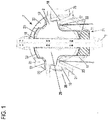
Fig. 1 is a side view of a hoisting machinery with a cooling system according to an embodiment of the invention; -
Fig. 2 is a vertical cross sectional view of the hoisting machinery with the cooling system according to the embodiment of the invention. -
Fig. 3 is a perspective view of a half-cut-away hoisting machine without the rotor. - A hoisting machinery 1 according to an embodiment of the invention is configured as an electric motor having a
stator 4 and a rotor 6 being mounted to amachine frame 2. Themachine frame 2 has a shell-like structure for partly covering the electric motor from one side thereof. - As can be seen in
Fig. 1 , themachine frame 2 has avertical rail slot 16 allowing aguide rail 9 to pass themachine frame 2. Theguide rail 9 is mounted to a not shown elevator shaft and is also used to guide an elevator car along theguide rail 9 during the up and down movement of the elevator car in the shaft. - The
machine frame 2 further compriseslower struts 24 and upper struts 25 on each of the left and right side andmachinery brakes 26 are mounted vertically between the outer end portions of thestruts 24, 25. - At the lower left and right sides of the
machine frame 2,rope openings 17 are formed in themachine frame 2 below thelower struts 24 so as to allowropes 23 to pass from inside the hoisting machinery 1 to the outside thereof. Theropes 23 are driven by the hoisting machinery 1 so as to make the elevator car move up or down in the shaft. Therope openings 17 also allow ambient air to flow towards the electric motor for cooling purpose. - At the middle left and right side of the
machine frame 2,lateral vent openings 18 are formed between thelower struts 24 and the upper struts 25 so as to allow ambient air to flow towards the electric motor for cooling purpose. Thelateral vent openings 18 are formed between respectivelower struts 24 and upper struts 25 of themachinery frame 2. - At the upper left and right side of the
machine frame 2,upper vent openings 19 are formed above the upper struts 25 so as to allow ambient air to flow towards the electric motor for cooling purpose. Theupper vent openings 19 are formed to lie in a substantially horizontal plane. - As can be seen in
Fig. 2 , themachine frame 2 comprises astator flange 3 which protrudes from the inner side of acentral portion 29 of the machine frame 2 (seeFig. 1 ) in a direction away from theguide rail 9 and is formed integrally with themachine frame 2. In this embodiment, thestator flange 3 has the shape of continuous ring. However, according to other embodiments, there might be a plurality of stator flanges which are placed along a ring-shaped path on the inner side of the machine frame. -
Fig. 2 also shows that themachine frame 2 has an upper projection which projects from themachine frame 2 to the upper side, and a lower projection which projects form themachine frame 2 to the lower side. Anupper fixing means 14 is fixed to the upper projection and to theguide rail 9, and a lower fixing means 15 is fixed to the lower projection and theguide rail 9. As a result, themachine frame 2 is fixed to theguide rail 9. - As can be seen in
Fig. 3 , thestator flange 3 hasstator flange openings 27 which correspond to therope openings 17 with respect to the circumferential direction of themachine frame 2. Thesestator flange openings 27 each have a dimension in the axial direction corresponding to a later describedrope groove portion 8 of the rotor 6, in which grooves for accommodating theropes 23 are provided. Therope groove portion 8 corresponds to the traction sheave according to the invention. - A ring-shaped
stator 4 is mounted to the distal end (left end inFig. 2 ) of thestator flange 3 at a radial outside position thereof and is fit onto a portion of thestator flange 3 which has a reduced dimension in the radial direction to form a seat against which thestator 4 is pressed in the axial direction by means of bolts. Thestator 4 comprises radially extending protrusions about which stator windings 5 are wound in a manner to general a radial magnetic flux. In this embodiment, the stator windings 5 are wound to have longer components extending in the axial direction of the hoisting machinery 1 and shorter components extending in the circumferential direction of the hoisting machinery 1. - The rotor 6 has a shell-like structure comprising a
rotor hub 11, therope groove portion 8 and a magnet mounting portion 7. Therotor hub 11 extends in the axial direction and is supported bybearings rotor fixing plate 10 mounted to theguide rail 9 through therail slot 16 of themachine frame 2. - The
rope groove portion 8 extends in the axial direction and within an axial range corresponding substantially to that of therotor hub 11 and is connected to therotor hub 11 by a ring-disc-like portion which is partly inclined to a vertical plane perpendicular to the rotor axis. Therope groove portion 8 comprise a plurality of grooves for accommodating theropes 23 connected to the elevator car. When the rotor 6 rotates, the rotational force is transmitted to theropes 23 via friction between theropes 23 and the rope grooves. - The magnet mounting portion 7 is integrally connected to the
rope groove portion 8 radially outside thereof and has a substantially U-shaped cross-sectional shape with the U opening towards thestator flange 3. The radially outer portion of the U-shaped magnet mounting portion 7 forms a ring on the radial inner side of whichmagnets 28 are fixed in such a manner that they are opposite to the stator windings 5 with a small gap between themagnets 28 and stator windings 5. - When the hoisting machinery 1 is operated, electricity is supplied and controlled by an electricity supply and control units (not shown) to the stator windings 5. As a result, most of the electric energy is transferred into a magnetic field which acts on the
magnets 28 of the rotor 6, and the rotor 6 is rotated so as the move the elevator car up or down via theropes 23. - However, a part of the electric energy is transferred by the stator windings 5 into heat which heats the stator core and its surroundings. The generated heat acts on the material of not only the windings 5 and the
stator 4 but also on that of isolators resulting in that these materials are prone to thermal aging such that the life span of the hoisting machinery would be deteriorated. Hence, sufficient cooling of the electric motor is important. - For this purpose, the hoisting machinery 1 according to the embodiment comprises a cooling system having
evaporator pipes 22 provided inside the hoisting machinery 1, condenser pipes 20 provided outside the hoisting machinery 1, and anexpansion tank 21 provided outside the hoisting machinery 1. - As can be seen in the
Fig. 2 , theexpansion tank 21 is provided at a position between themachine frame 2 and theguide rail 9. In more detail, making reference toFig. 1 , thecentral portion 29 of themachine frame 2 extends substantially within a vertical plane. Thiscentral portion 29 has a lower portion which is divided by therail slot 16, is located between the tworope openings 17 and has a lower borderline which is curved concentrically to therope groove portion 8. Below this curved borderline, themachine frame 2 has a displacedportion 31 which is displaced toward the rotor 6 such that a space is generated between this displacedportion 31 of themachine frame 2 and theguide rail 9. According to one embodiment of the invention, this space is used to mount theexpansion tank 21 which is shaped to have an upper edge corresponding to the curvature of the lower borderline. - Furthermore, the
expansion tank 21 may be supported by the lower fixing means 15. Hence, an already existing structure, namely the lower fixing means 15, can be used for supporting theexpansion tank 21 such that no additional structural feature needs to be provided for this purpose. - As is shown in
Figs. 1 and2 , theevaporator pipes 22 exit from theexpansion tank 21 at positions right and left from and close to theguide rail 9, and they are guided to enter the inside of themachine frame 2 via therail slot 16 at both sides of theguide rail 9. Alternatively, theevaporator pipes 22 can enter the inside of themachine frame 2 through through-holes provided in atransition portion 30 between thecentral portion 29 and the displacedportion 31 on both sides of theguide rail 9. Such a configuration is shown inFig. 3 . - Inside the
machine frame 2, theevaporator pipes 22 are guided to the radial inner side of thestator flange 3 and are arranged in a meandering manner from the lower portion of thestator flange 3 to the upper portion thereof. The radial inner side of thestator flange 3 has axially extendingribs 32 which are provided to increase the cooling surface of thestator flange 3 for the purpose of improving natural cooling. In this embodiment, the meandering arrangement of theevaporator pipes 22 is such that portions of theevaporator pipes 22, which extend in the axial direction of the hoisting machinery, are placed inrecesses 33 between theribs 32, whereas circumferentially portions of theevaporator pipes 22 cross over theribs 32. - Making reference to
Fig. 1 , the meandering portions of theevaporator pipes 22 are provided on the right side and the left side of therail slot 16, respectively. At the upper side of the meandering portions, theevaporator pipes 22 exit themachine frame 2 through therail slot 16 between theguide rail 9 and themachine frame 2 at both sides of theguide rail 9, respectively, and merge into the condenser pipes 20 which are provided outside themachine frame 2. - In an alternative embodiment shown in
Fig. 3 , theevaporator pipes 22 penetrate thestator flange 3 so as to exit themachine frame 2 and then merge into the condenser pipes 20. - In a possible embodiment of the invention, as can be seen in
Fig. 1 , thecentral portion 29 of themachine frame 2 comprises, comparable to the lower side, also at the upper side a curved borderline which is concentric to therope groove portion 8 and defines an upper transition portion 34 which is inclined towards the rotor with respect to thecentral portion 29. The condenser pipes 20 are guided on both left and right sides of therail slot 16 along the upper transition portion 34 in the circumferential direction towardsrecesses 35 having a substantially trapezoidal shape with curved base lines and a vertical leg and a horizontal leg. Each condenser pipe 20 is guided along the vertical leg and the inner curved base line of therecesses 35. Furthermore, the upper vent opening 19 is formed along the horizontal leg of thetrapezoidal recess 35, and the condenser pipes 20 enter theupper vent openings 19. Then, the condenser pipes 20 are guided behind the upper struts 25, are guided along a radially inner edge of thelateral vent openings 18, cross the lower struts 25 on the outside of themachine frame 2, and are guided along the radial inner edges of therope openings 17 towards theexpansion tank 21. Here, the condenser pipes 20 are connected to theexpansion tank 21. - In this manner, the
expansion tank 21, theevaporator pipes 22 and the condenser pipes 20 form a closed free flow cooling system along which a cooling medium can circulate. - In operation of the hoisting machinery 1, the stator windings 5 transfer part of the electric energy into heat which heats mainly the
stator 4. This heat is transmitted to theevaporator pipes 22 and the cooling medium inside theevaporator pipes 22 is evaporated, i.e. it makes a phase transition from liquid to gas. This gas is rises upwards and exits theevaporator pipes 22 at the upper portion of the hoisting machinery 1 where it enters the condenser pipes 20 which have a lower temperature due to being exposed to the ambient air. In the condenser pipes 20, the cooling medium makes a phase transition from gas to liquid such that the cooling medium is allowed to flow back to theexpansion tank 21 due to gravity. - In the
evaporator pipes 22, the cooling medium absorbs heat energy from thestator 4 by evaporation of the cooling medium. The vapor is transmitted to the condenser pipes 20 where the heat energy is released to the ambient air due to condensation of the vapor. - The cooling system is adjusted in such a manner that the evaporation surface temperature of the cooling medium is in a range of 80 to 90°C.
- Preferably, the
evaporator pipes 22 and the condenser pipes 20 are made from copper. However, theevaporator pipes 22 and the condenser pipes 20 can also be made from aluminum or steel. - Preferably, the cooling system is adapted to be operable with atmospheric pressure or over-pressure.
- According to another embodiment, the evaporator pipes are not provided at the inner radial surface of the stator flange but on the outer radial surface of the stator flange.
- According to a further possible embodiment, the condenser pipes comprise cooling fins which improve the cooling performance of the cooling medium within the condenser pipes. The cooling fins may be provided on the outer surface of the condenser pipes in a manner to project in a radial direction of the condenser pipes and to extend in a longitudinal direction of the condenser pipes. The number of cooling fins for each condenser pipe can be one or more.
Claims (15)
- A hoisting machinery (1) for an elevator, comprising:a frame (2) with a stator flange (3),a stator (4) supported at the stator flange (3),stator windings (5) arranged at the stator (4), anda cooling system having an evaporator part (22), a condenser part (20) and an expansion tank (21), wherein a cooling medium can circulate through the cooling system, whereinthe evaporator part (22) is arranged at the stator flange (3) in a manner to allow the cooling medium to receive heat generated by the stator windings (5),the condenser part (20) is arranged at the frame (2) in a manner to be in contact with ambient air, andthe expansion tank (21) is arranged at the frame (2) in a manner to allow the condensed cooling medium to be collected.
- The hoisting machinery (1) according to claim 1, whereinthe evaporator part (22) is an evaporator pipe which is arranged in a meandering shape at the stator flange (3).
- The hoisting machinery (1) according to claim 1 or 2, whereinthe evaporator part (22) is arranged on an inner radial surface of the stator flange (3).
- The hoisting machinery (1) according to claim 1 or 2, wherein the evaporator part (22) is arranged on an outer radial surface of the stator flange (3).
- The hoisting machinery (1) according to any one of claims 1 to 4, whereinthe frame (2) constitutes a part of a hoisting machinery housing and the evaporator part (22) is arranged inside the hoisting machinery housing, andthe condenser part (20) and the expansion tank (21) are arranged outside the hoisting machinery housing.
- The hoisting machinery (1) according to claim 5, whereinthe evaporator part (22) exits the hoisting machinery housing at an upper portion of the hoisting machinery housing and is connected to the condenser part (20).
- The hoisting machinery (1) according to claim 4, whereinthe expansion tank (21) is arranged on a lower side of the hoisting machine housing and is connected to the evaporator part (22) and the condenser part (20).
- The hoisting machinery (1) according to claim 7, wherein the expansion tank (21) is arranged between the frame (2) and a guide rail (9).
- The hoisting machinery (1) according to any one of the preceding claims, further comprising frame fixing means (14, 15) for fixing the frame (2) to a guide rail (9) for guiding an elevator car in a shaft.
- The hoisting machinery (1) according to claim 9, wherein the expansion tank (21) is supported with the frame fixing means (15).
- The hoisting machinery (1) according to any of the preceding claims, wherein the condenser part (20) is heat conductively connected to a guide rail (9) for guiding an elevator car in a shaft.
- The hoisting machinery (1) according to any of the preceding claims, wherein the condenser part (20) comprises cooling fins.
- The hoisting machinery (1) according to any one of claims 1 to 12, wherein the stator (4) is part of an electric motor having an outer rotor (6).
- The hoisting machinery (1) according to any one of claims 1 to 13, wherein the electric motor is configured as a radial flux machinery.
- The hoisting machinery (1) according to claim 13 or 14, wherein the electric motor has a rotor (6) comprising a traction sheave (8) which has a smaller diameter than a magnet mounting portion (7) of the rotor (6) for mounting rotor magnets (28).
Priority Applications (1)
| Application Number | Priority Date | Filing Date | Title |
|---|---|---|---|
| EP17203477.9A EP3489185B1 (en) | 2017-11-24 | 2017-11-24 | Cooling solution for hoisting machinery |
Applications Claiming Priority (1)
| Application Number | Priority Date | Filing Date | Title |
|---|---|---|---|
| EP17203477.9A EP3489185B1 (en) | 2017-11-24 | 2017-11-24 | Cooling solution for hoisting machinery |
Publications (2)
| Publication Number | Publication Date |
|---|---|
| EP3489185A1 true EP3489185A1 (en) | 2019-05-29 |
| EP3489185B1 EP3489185B1 (en) | 2020-07-29 |
Family
ID=60452510
Family Applications (1)
| Application Number | Title | Priority Date | Filing Date |
|---|---|---|---|
| EP17203477.9A Active EP3489185B1 (en) | 2017-11-24 | 2017-11-24 | Cooling solution for hoisting machinery |
Country Status (1)
| Country | Link |
|---|---|
| EP (1) | EP3489185B1 (en) |
Citations (2)
| Publication number | Priority date | Publication date | Assignee | Title |
|---|---|---|---|---|
| WO2009075672A1 (en) * | 2007-12-10 | 2009-06-18 | Otis Elevator Company | Integrated elevator machine motor and drive |
| WO2009151434A1 (en) * | 2008-06-09 | 2009-12-17 | Otis Elevator Company | Elevator machine motor and drive and cooling thereof |
-
2017
- 2017-11-24 EP EP17203477.9A patent/EP3489185B1/en active Active
Patent Citations (2)
| Publication number | Priority date | Publication date | Assignee | Title |
|---|---|---|---|---|
| WO2009075672A1 (en) * | 2007-12-10 | 2009-06-18 | Otis Elevator Company | Integrated elevator machine motor and drive |
| WO2009151434A1 (en) * | 2008-06-09 | 2009-12-17 | Otis Elevator Company | Elevator machine motor and drive and cooling thereof |
Also Published As
| Publication number | Publication date |
|---|---|
| EP3489185B1 (en) | 2020-07-29 |
Similar Documents
| Publication | Publication Date | Title |
|---|---|---|
| KR101924294B1 (en) | Stator used for motor, motor and ventilation cooling method for motor | |
| JP7013285B2 (en) | Heat pipes, rotors and rotary machines | |
| US9819246B2 (en) | Electrical machine and controller and methods of assembling the same | |
| US7880348B2 (en) | Method of installing a permanent magnet motor in a cooling tower and a shroud used in connection therewith | |
| US12184122B2 (en) | Enhancements to cooling means for axial flux generators | |
| KR20100106247A (en) | Arrangement and method for cooling an electrical machine | |
| EP2902619B1 (en) | Cooling arrangement for a direct drive wind turbine | |
| US20160352201A1 (en) | Integrated heat dissipative structure for electric machine | |
| US20160076522A1 (en) | Wind turbine architecture | |
| KR102927962B1 (en) | Cooling of electrical machines | |
| CN105811660A (en) | Rotating device | |
| US9698641B2 (en) | Active segment of a wind turbine rotary electric machine, rotary electric machine, and wind turbine | |
| CN103390942B (en) | Generator is particularly used for the generator of wind turbine | |
| JP6406913B2 (en) | In-wheel motor cooling structure | |
| EP3489185B1 (en) | Cooling solution for hoisting machinery | |
| CN207304293U (en) | Motor | |
| JP2019134667A (en) | Electric motor assembly | |
| JP2017085830A (en) | Rotary electric machine | |
| CN213879471U (en) | Permanent magnet motors for air compressors and corresponding air compressors | |
| CN105531912B (en) | Cooling of machines for elevator systems | |
| US10550851B2 (en) | Fan having an impeller including a resin portion and a metal plate | |
| US12609594B2 (en) | Magnetic geared electrical machine, power generation system, and drive system | |
| KR102379441B1 (en) | Single stage low vibration turbine with impeller and fan | |
| KR101265131B1 (en) | Electric motor and electric vehicle having the same | |
| US20250357820A1 (en) | Electric traction motor for a vehicle, with a cooling device |
Legal Events
| Date | Code | Title | Description |
|---|---|---|---|
| PUAI | Public reference made under article 153(3) epc to a published international application that has entered the european phase |
Free format text: ORIGINAL CODE: 0009012 |
|
| STAA | Information on the status of an ep patent application or granted ep patent |
Free format text: STATUS: REQUEST FOR EXAMINATION WAS MADE |
|
| 17P | Request for examination filed |
Effective date: 20180817 |
|
| AK | Designated contracting states |
Kind code of ref document: A1 Designated state(s): AL AT BE BG CH CY CZ DE DK EE ES FI FR GB GR HR HU IE IS IT LI LT LU LV MC MK MT NL NO PL PT RO RS SE SI SK SM TR |
|
| AX | Request for extension of the european patent |
Extension state: BA ME |
|
| RIC1 | Information provided on ipc code assigned before grant |
Ipc: B66B 11/04 20060101AFI20191120BHEP |
|
| GRAP | Despatch of communication of intention to grant a patent |
Free format text: ORIGINAL CODE: EPIDOSNIGR1 |
|
| STAA | Information on the status of an ep patent application or granted ep patent |
Free format text: STATUS: GRANT OF PATENT IS INTENDED |
|
| INTG | Intention to grant announced |
Effective date: 20200221 |
|
| GRAS | Grant fee paid |
Free format text: ORIGINAL CODE: EPIDOSNIGR3 |
|
| GRAA | (expected) grant |
Free format text: ORIGINAL CODE: 0009210 |
|
| STAA | Information on the status of an ep patent application or granted ep patent |
Free format text: STATUS: THE PATENT HAS BEEN GRANTED |
|
| AK | Designated contracting states |
Kind code of ref document: B1 Designated state(s): AL AT BE BG CH CY CZ DE DK EE ES FI FR GB GR HR HU IE IS IT LI LT LU LV MC MK MT NL NO PL PT RO RS SE SI SK SM TR |
|
| REG | Reference to a national code |
Ref country code: CH Ref legal event code: EP |
|
| REG | Reference to a national code |
Ref country code: DE Ref legal event code: R096 Ref document number: 602017020484 Country of ref document: DE |
|
| REG | Reference to a national code |
Ref country code: AT Ref legal event code: REF Ref document number: 1295556 Country of ref document: AT Kind code of ref document: T Effective date: 20200815 |
|
| REG | Reference to a national code |
Ref country code: IE Ref legal event code: FG4D |
|
| REG | Reference to a national code |
Ref country code: LT Ref legal event code: MG4D |
|
| REG | Reference to a national code |
Ref country code: NL Ref legal event code: MP Effective date: 20200729 |
|
| REG | Reference to a national code |
Ref country code: AT Ref legal event code: MK05 Ref document number: 1295556 Country of ref document: AT Kind code of ref document: T Effective date: 20200729 |
|
| PG25 | Lapsed in a contracting state [announced via postgrant information from national office to epo] |
Ref country code: PT Free format text: LAPSE BECAUSE OF FAILURE TO SUBMIT A TRANSLATION OF THE DESCRIPTION OR TO PAY THE FEE WITHIN THE PRESCRIBED TIME-LIMIT Effective date: 20201130 Ref country code: FI Free format text: LAPSE BECAUSE OF FAILURE TO SUBMIT A TRANSLATION OF THE DESCRIPTION OR TO PAY THE FEE WITHIN THE PRESCRIBED TIME-LIMIT Effective date: 20200729 Ref country code: SE Free format text: LAPSE BECAUSE OF FAILURE TO SUBMIT A TRANSLATION OF THE DESCRIPTION OR TO PAY THE FEE WITHIN THE PRESCRIBED TIME-LIMIT Effective date: 20200729 Ref country code: AT Free format text: LAPSE BECAUSE OF FAILURE TO SUBMIT A TRANSLATION OF THE DESCRIPTION OR TO PAY THE FEE WITHIN THE PRESCRIBED TIME-LIMIT Effective date: 20200729 Ref country code: NO Free format text: LAPSE BECAUSE OF FAILURE TO SUBMIT A TRANSLATION OF THE DESCRIPTION OR TO PAY THE FEE WITHIN THE PRESCRIBED TIME-LIMIT Effective date: 20201029 Ref country code: BG Free format text: LAPSE BECAUSE OF FAILURE TO SUBMIT A TRANSLATION OF THE DESCRIPTION OR TO PAY THE FEE WITHIN THE PRESCRIBED TIME-LIMIT Effective date: 20201029 Ref country code: HR Free format text: LAPSE BECAUSE OF FAILURE TO SUBMIT A TRANSLATION OF THE DESCRIPTION OR TO PAY THE FEE WITHIN THE PRESCRIBED TIME-LIMIT Effective date: 20200729 Ref country code: GR Free format text: LAPSE BECAUSE OF FAILURE TO SUBMIT A TRANSLATION OF THE DESCRIPTION OR TO PAY THE FEE WITHIN THE PRESCRIBED TIME-LIMIT Effective date: 20201030 Ref country code: LT Free format text: LAPSE BECAUSE OF FAILURE TO SUBMIT A TRANSLATION OF THE DESCRIPTION OR TO PAY THE FEE WITHIN THE PRESCRIBED TIME-LIMIT Effective date: 20200729 Ref country code: ES Free format text: LAPSE BECAUSE OF FAILURE TO SUBMIT A TRANSLATION OF THE DESCRIPTION OR TO PAY THE FEE WITHIN THE PRESCRIBED TIME-LIMIT Effective date: 20200729 |
|
| PG25 | Lapsed in a contracting state [announced via postgrant information from national office to epo] |
Ref country code: PL Free format text: LAPSE BECAUSE OF FAILURE TO SUBMIT A TRANSLATION OF THE DESCRIPTION OR TO PAY THE FEE WITHIN THE PRESCRIBED TIME-LIMIT Effective date: 20200729 Ref country code: LV Free format text: LAPSE BECAUSE OF FAILURE TO SUBMIT A TRANSLATION OF THE DESCRIPTION OR TO PAY THE FEE WITHIN THE PRESCRIBED TIME-LIMIT Effective date: 20200729 Ref country code: RS Free format text: LAPSE BECAUSE OF FAILURE TO SUBMIT A TRANSLATION OF THE DESCRIPTION OR TO PAY THE FEE WITHIN THE PRESCRIBED TIME-LIMIT Effective date: 20200729 Ref country code: IS Free format text: LAPSE BECAUSE OF FAILURE TO SUBMIT A TRANSLATION OF THE DESCRIPTION OR TO PAY THE FEE WITHIN THE PRESCRIBED TIME-LIMIT Effective date: 20201129 |
|
| PG25 | Lapsed in a contracting state [announced via postgrant information from national office to epo] |
Ref country code: NL Free format text: LAPSE BECAUSE OF FAILURE TO SUBMIT A TRANSLATION OF THE DESCRIPTION OR TO PAY THE FEE WITHIN THE PRESCRIBED TIME-LIMIT Effective date: 20200729 |
|
| PG25 | Lapsed in a contracting state [announced via postgrant information from national office to epo] |
Ref country code: DK Free format text: LAPSE BECAUSE OF FAILURE TO SUBMIT A TRANSLATION OF THE DESCRIPTION OR TO PAY THE FEE WITHIN THE PRESCRIBED TIME-LIMIT Effective date: 20200729 Ref country code: CZ Free format text: LAPSE BECAUSE OF FAILURE TO SUBMIT A TRANSLATION OF THE DESCRIPTION OR TO PAY THE FEE WITHIN THE PRESCRIBED TIME-LIMIT Effective date: 20200729 Ref country code: RO Free format text: LAPSE BECAUSE OF FAILURE TO SUBMIT A TRANSLATION OF THE DESCRIPTION OR TO PAY THE FEE WITHIN THE PRESCRIBED TIME-LIMIT Effective date: 20200729 Ref country code: SM Free format text: LAPSE BECAUSE OF FAILURE TO SUBMIT A TRANSLATION OF THE DESCRIPTION OR TO PAY THE FEE WITHIN THE PRESCRIBED TIME-LIMIT Effective date: 20200729 Ref country code: EE Free format text: LAPSE BECAUSE OF FAILURE TO SUBMIT A TRANSLATION OF THE DESCRIPTION OR TO PAY THE FEE WITHIN THE PRESCRIBED TIME-LIMIT Effective date: 20200729 Ref country code: IT Free format text: LAPSE BECAUSE OF FAILURE TO SUBMIT A TRANSLATION OF THE DESCRIPTION OR TO PAY THE FEE WITHIN THE PRESCRIBED TIME-LIMIT Effective date: 20200729 |
|
| REG | Reference to a national code |
Ref country code: DE Ref legal event code: R097 Ref document number: 602017020484 Country of ref document: DE |
|
| PG25 | Lapsed in a contracting state [announced via postgrant information from national office to epo] |
Ref country code: AL Free format text: LAPSE BECAUSE OF FAILURE TO SUBMIT A TRANSLATION OF THE DESCRIPTION OR TO PAY THE FEE WITHIN THE PRESCRIBED TIME-LIMIT Effective date: 20200729 |
|
| PLBE | No opposition filed within time limit |
Free format text: ORIGINAL CODE: 0009261 |
|
| STAA | Information on the status of an ep patent application or granted ep patent |
Free format text: STATUS: NO OPPOSITION FILED WITHIN TIME LIMIT |
|
| PG25 | Lapsed in a contracting state [announced via postgrant information from national office to epo] |
Ref country code: SK Free format text: LAPSE BECAUSE OF FAILURE TO SUBMIT A TRANSLATION OF THE DESCRIPTION OR TO PAY THE FEE WITHIN THE PRESCRIBED TIME-LIMIT Effective date: 20200729 Ref country code: MC Free format text: LAPSE BECAUSE OF FAILURE TO SUBMIT A TRANSLATION OF THE DESCRIPTION OR TO PAY THE FEE WITHIN THE PRESCRIBED TIME-LIMIT Effective date: 20200729 |
|
| REG | Reference to a national code |
Ref country code: CH Ref legal event code: PL |
|
| 26N | No opposition filed |
Effective date: 20210430 |
|
| PG25 | Lapsed in a contracting state [announced via postgrant information from national office to epo] |
Ref country code: LU Free format text: LAPSE BECAUSE OF NON-PAYMENT OF DUE FEES Effective date: 20201124 |
|
| REG | Reference to a national code |
Ref country code: BE Ref legal event code: MM Effective date: 20201130 |
|
| PG25 | Lapsed in a contracting state [announced via postgrant information from national office to epo] |
Ref country code: CH Free format text: LAPSE BECAUSE OF NON-PAYMENT OF DUE FEES Effective date: 20201130 Ref country code: SI Free format text: LAPSE BECAUSE OF FAILURE TO SUBMIT A TRANSLATION OF THE DESCRIPTION OR TO PAY THE FEE WITHIN THE PRESCRIBED TIME-LIMIT Effective date: 20200729 Ref country code: LI Free format text: LAPSE BECAUSE OF NON-PAYMENT OF DUE FEES Effective date: 20201130 |
|
| PG25 | Lapsed in a contracting state [announced via postgrant information from national office to epo] |
Ref country code: IE Free format text: LAPSE BECAUSE OF NON-PAYMENT OF DUE FEES Effective date: 20201124 |
|
| PG25 | Lapsed in a contracting state [announced via postgrant information from national office to epo] |
Ref country code: TR Free format text: LAPSE BECAUSE OF FAILURE TO SUBMIT A TRANSLATION OF THE DESCRIPTION OR TO PAY THE FEE WITHIN THE PRESCRIBED TIME-LIMIT Effective date: 20200729 Ref country code: MT Free format text: LAPSE BECAUSE OF FAILURE TO SUBMIT A TRANSLATION OF THE DESCRIPTION OR TO PAY THE FEE WITHIN THE PRESCRIBED TIME-LIMIT Effective date: 20200729 Ref country code: CY Free format text: LAPSE BECAUSE OF FAILURE TO SUBMIT A TRANSLATION OF THE DESCRIPTION OR TO PAY THE FEE WITHIN THE PRESCRIBED TIME-LIMIT Effective date: 20200729 |
|
| PG25 | Lapsed in a contracting state [announced via postgrant information from national office to epo] |
Ref country code: MK Free format text: LAPSE BECAUSE OF FAILURE TO SUBMIT A TRANSLATION OF THE DESCRIPTION OR TO PAY THE FEE WITHIN THE PRESCRIBED TIME-LIMIT Effective date: 20200729 |
|
| PG25 | Lapsed in a contracting state [announced via postgrant information from national office to epo] |
Ref country code: BE Free format text: LAPSE BECAUSE OF NON-PAYMENT OF DUE FEES Effective date: 20201130 |
|
| P01 | Opt-out of the competence of the unified patent court (upc) registered |
Effective date: 20230525 |
|
| PGFP | Annual fee paid to national office [announced via postgrant information from national office to epo] |
Ref country code: DE Payment date: 20251119 Year of fee payment: 9 |
|
| PGFP | Annual fee paid to national office [announced via postgrant information from national office to epo] |
Ref country code: GB Payment date: 20251121 Year of fee payment: 9 |
|
| PGFP | Annual fee paid to national office [announced via postgrant information from national office to epo] |
Ref country code: FR Payment date: 20251126 Year of fee payment: 9 |