EP3489156A1 - Packer machine and wrapping method to produce a pack of smoking articles provided with two rigid containers one inside the other - Google Patents
Packer machine and wrapping method to produce a pack of smoking articles provided with two rigid containers one inside the other Download PDFInfo
- Publication number
- EP3489156A1 EP3489156A1 EP18208128.1A EP18208128A EP3489156A1 EP 3489156 A1 EP3489156 A1 EP 3489156A1 EP 18208128 A EP18208128 A EP 18208128A EP 3489156 A1 EP3489156 A1 EP 3489156A1
- Authority
- EP
- European Patent Office
- Prior art keywords
- panel
- wrapping
- blank
- inner container
- drum
- Prior art date
- Legal status (The legal status is an assumption and is not a legal conclusion. Google has not performed a legal analysis and makes no representation as to the accuracy of the status listed.)
- Withdrawn
Links
Images


Classifications
-
- B—PERFORMING OPERATIONS; TRANSPORTING
- B65—CONVEYING; PACKING; STORING; HANDLING THIN OR FILAMENTARY MATERIAL
- B65B—MACHINES, APPARATUS OR DEVICES FOR, OR METHODS OF, PACKAGING ARTICLES OR MATERIALS; UNPACKING
- B65B19/00—Packaging rod-shaped or tubular articles susceptible to damage by abrasion or pressure, e.g. cigarettes, cigars, macaroni, spaghetti, drinking straws or welding electrodes
- B65B19/02—Packaging cigarettes
- B65B19/22—Wrapping the cigarettes; Packaging the cigarettes in containers formed by folding wrapping material around formers
-
- B—PERFORMING OPERATIONS; TRANSPORTING
- B65—CONVEYING; PACKING; STORING; HANDLING THIN OR FILAMENTARY MATERIAL
- B65B—MACHINES, APPARATUS OR DEVICES FOR, OR METHODS OF, PACKAGING ARTICLES OR MATERIALS; UNPACKING
- B65B19/00—Packaging rod-shaped or tubular articles susceptible to damage by abrasion or pressure, e.g. cigarettes, cigars, macaroni, spaghetti, drinking straws or welding electrodes
- B65B19/02—Packaging cigarettes
- B65B19/12—Inserting the cigarettes, or wrapped groups thereof, into preformed containers
- B65B19/20—Inserting the cigarettes, or wrapped groups thereof, into preformed containers into boxes with hinged lids
-
- B—PERFORMING OPERATIONS; TRANSPORTING
- B65—CONVEYING; PACKING; STORING; HANDLING THIN OR FILAMENTARY MATERIAL
- B65B—MACHINES, APPARATUS OR DEVICES FOR, OR METHODS OF, PACKAGING ARTICLES OR MATERIALS; UNPACKING
- B65B19/00—Packaging rod-shaped or tubular articles susceptible to damage by abrasion or pressure, e.g. cigarettes, cigars, macaroni, spaghetti, drinking straws or welding electrodes
- B65B19/02—Packaging cigarettes
- B65B19/22—Wrapping the cigarettes; Packaging the cigarettes in containers formed by folding wrapping material around formers
- B65B19/223—Wrapping the cigarettes; Packaging the cigarettes in containers formed by folding wrapping material around formers in a curved path; in a combination of straight and curved paths, e.g. on rotary tables or other endless conveyors
-
- B—PERFORMING OPERATIONS; TRANSPORTING
- B65—CONVEYING; PACKING; STORING; HANDLING THIN OR FILAMENTARY MATERIAL
- B65D—CONTAINERS FOR STORAGE OR TRANSPORT OF ARTICLES OR MATERIALS, e.g. BAGS, BARRELS, BOTTLES, BOXES, CANS, CARTONS, CRATES, DRUMS, JARS, TANKS, HOPPERS, FORWARDING CONTAINERS; ACCESSORIES, CLOSURES, OR FITTINGS THEREFOR; PACKAGING ELEMENTS; PACKAGES
- B65D85/00—Containers, packaging elements or packages, specially adapted for particular articles or materials
- B65D85/07—Containers, packaging elements or packages, specially adapted for particular articles or materials for compressible or flexible articles
- B65D85/08—Containers, packaging elements or packages, specially adapted for particular articles or materials for compressible or flexible articles rod-shaped or tubular
- B65D85/10—Containers, packaging elements or packages, specially adapted for particular articles or materials for compressible or flexible articles rod-shaped or tubular for cigarettes
- B65D85/1036—Containers formed by erecting a rigid or semi-rigid blank
- B65D85/1045—Containers formed by erecting a rigid or semi-rigid blank having a cap-like lid hinged to an edge
- B65D85/1056—Containers formed by erecting a rigid or semi-rigid blank having a cap-like lid hinged to an edge characterized by the lid
- B65D85/10568—Containers formed by erecting a rigid or semi-rigid blank having a cap-like lid hinged to an edge characterized by the lid opening of the lid opens simultaneously an inner package within the container
Definitions
- the present invention relates to a packer machine and to a wrapping method to produce a pack of smoking articles provided with two rigid containers one inside the other.
- the present invention finds advantageous application in producing a pack of cigarettes containing a group of cigarettes, to which the following disclosure will make explicit reference without thereby losing generality.
- a pack of cigarettes comprising a group of cigarettes, a rigid inner container having a through pull-out opening through which the cigarettes can be withdrawn, and a rigid outer container which contains the inner container and is provided with a hinged lid; preferably, a closing tab is coupled to the inner container, which is glued, by means of re-stick glue, to the inner container to cover the pull-out opening.
- a packer machine which produces the pack of cigarettes described above and comprises: a first wrapping drum having a vertical rotation axis (i.e. arranged horizontally), which receives a first blank and then the group of cigarettes and folds the first blank around the group of cigarettes to form the inner container, a first gluing unit that is arranged downstream of the first wrapping drum and applies glue to opposite side walls of the first container to stabilize the shape of the first container itself, a pair of first drying drums arranged downstream of the first gluing unit to allow the glue to set, a second wrapping drum having a vertical rotation axis (i.e.
- a second gluing unit which is arranged downstream of the second wrapping drum and applies glue to opposite side walls of the second container to stabilize the shape of the second container itself, and a pair of second drying drums arranged downstream of the second gluing unit to allow the glue to set.
- the packer machine described in patent US8123030B2 is very bulky (i.e. it occupies a large surface area) and above all has many parts that are hard to reach (i.e. an operator cannot reach, by hand, many parts of the packer machine while standing in front of the packer machine, but in order to reach many parts of the packer machine by hand one must somehow "enter” the packer machine by making demanding and tiring "contortions "). Consequently, assembly and above all maintenance and periodic cleaning of the packer machine described in patent US8123030B2 are extremely laborious and particularly long (with a consequent extremely long maintenance and cleaning down-time of the machine and therefore clearly detrimental to the average productivity of the packer machine in the long run).
- the packer machine described in the patent US8123030B2 is adapted to operate only with an intermittent motion (i.e. a motion that cyclically alternates stopping steps and motion steps) and then subjects the mechanics to continuous accelerations/decelerations which do not allow a high hourly productivity to be obtained (i.e. a large number of packs of cigarettes produced per time unit) while maintaining an optimal production quality.
- an intermittent motion i.e. a motion that cyclically alternates stopping steps and motion steps
- continuous accelerations/decelerations which do not allow a high hourly productivity to be obtained (i.e. a large number of packs of cigarettes produced per time unit) while maintaining an optimal production quality.
- the object of the present invention is to provide a packer machine and a wrapping method to produce a pack of smoking articles provided with two rigid containers one inside the other, which packer machine and wrapping method are free from the drawbacks described above and are, at the same time, easy and inexpensive to produce.
- a packer machine and a wrapping method are provided to produce a pack of smoking articles provided with two rigid containers one inside the other, according to what is claimed in the attached claims.
- the pack 1 of cigarettes comprises an outer container 2 made of a cup-shaped rigid cardboard or paperboard.
- the outer container 2 has an open upper end 3 and is provided with a lid 4, which is cup-shaped and is hinged to the outer container 2 along a hinge 5 (illustrated in Figure 2 ) to rotate relative to the outer container 2, between an open position (illustrated in Figure 3 ) and a closed position (illustrated in Figures 1 and 2 ) of the open upper end 3.
- the outer container 2 has a substantially rectangular parallelepiped shape orientated in a prevalently vertical development direction, is cup-shaped, and has the open upper end 3, a lower wall 6 opposite the open upper end 3, a front wall 7 and a rear wall 8 (where the hinge 5 is obtained) parallel and opposite to one another, and two side walls 9 parallel and opposite to each other. Between the front 7, rear 8 and side 9 walls of the outer container 2, four longitudinal edges are defined, whereas between the walls 7, 8 and 9 and the lower wall 6 of the outer container 2, four transverse edges are defined.
- the lid 4 has a substantially rectangular parallelepiped shape, is cup-shaped, and has an open lower end (facing the open upper end 3 of the outer container 2 when the lid 4 is in the closed position), an upper wall 10 (which is parallel and opposite to the lower wall 6 of the outer container 2 when the lid 4 is in the closed position), a front wall 11 (which is parallel to and aligned with the front wall 7 of the outer container 2 when the lid 4 is in the closed position) a rear wall 12 (which is parallel to and aligned with the rear wall 8 of the outer container 2 when the lid 4 is in the closed position and is hinged to the rear wall 8 of the outer container 2 along the hinge 5), and two side walls 13 parallel and opposite to each other (which are parallel and aligned, in particular coplanar and adjacent, to the side walls 9 of the outer container 2 when the lid 4 is in the closed position).
- the longitudinal edges and transverse edges of the lid 4 are parallel to and aligned with the corresponding longitudinal and transverse edges of the outer container 2 when the lid 4 is in the closed position.
- the pack 1 of cigarettes comprises an inner container 14, which is fixed (normally by gluing) to the inside of the outer container 2 to partially protrude to the outside of the open upper end 3 and to engage a corresponding inner surface of the lid 4 when the lid 4 itself is arranged in said closed position.
- the inner container 14 comprises a front wall 15, which is parallel to and rests against the front wall 7 of the container 2, two side walls 16 which are folded by 90° relative to the front wall 15 and are parallel to and rest against the side walls 9 of the container 2, a rear wall 17 which is folded by 90° relative to the side walls 16, is parallel to the front wall 15 and is parallel to, rests against and is glued to the rear wall 8 of the container 2, an upper wall 18 which is perpendicular to the walls 15, 16 and 17, and a lower wall 19 which is parallel and opposite to the upper wall 18, is perpendicular to the walls 15, 16 and 17, and is parallel to and rests against the lower wall 6 of the container 2.
- the inner container 14 also has the function of keeping the lid 4 in the closed position with a given force to avoid undesired openings of the lid 4; said "locking" function of the lid 4 in the closed position is carried out due to the fact that when the lid 4 is in the closed position the inner container 14 partially protrudes from the open end of the container 2 and thus engages a corresponding inner surface of the lid 4: in this way, to open the lid 4 it is necessary to elastically and slightly deform the lid 4 and/or the inner container 14 and therefore it is necessary to apply a given force to the lid 4 to open the lid 4.
- the inner container 14 has a pull-out opening 20 which is arranged at the centre and involves a portion of the front wall 15 of the inner container 14 and a portion of the upper wall 18 of the inner container 14.
- the pull-out opening 20 is formed by making a closed-shaped through incision through the inner container 14 which internally delimits a disposable portion of the inner container 14 which is removed, so as to leave a hole (which forms the extraction opening 20).
- the extraction opening 20 of the inner container 14 is normally closed by a reusable closing tab 21 which is fixed to the inner container 14 by means of the re-stick glue which is arranged around the pull-out opening 20 to allow the closing tab 21 to be (i.e. at each opening of the pack 1 of cigarettes) partially separated from the inner container 14 several times and then fixed again to the inner container 14 (at each closing of the pack 1 of cigarettes).
- the re-stick glue is a glue that does not dry after its application and therefore allows the separation and subsequent re-adhesion of the closing tab 21 to the underlying inner container 14 to be repeated several times.
- the closing tab 21 is provided with a connecting flap 22, which is glued in a permanent and non-separable manner to the inner surface of the front wall 11 of the lid 4 by means of the permanent glue 26 (illustrated in Figure 8 ) which is applied to the outer surface 27 of the closing tab 21 (i.e. to the surface of the closing tab 21 facing outwards, i.e. from the opposite wall of the inner container 14). In this way, by opening or closing the lid 4, the closing tab 21 is simultaneously opened and closed as well.
- the outer surface of the connecting flap 22 of the closing tab 21 is glued in a permanent and not separable manner to the inner surface of the front wall 11 of the lid 4 by permanent glue so that, by opening and closing the lid 4, the closing tab 21 is simultaneously and automatically opened and closed as well.
- a group 23 of cigarettes is arranged (illustrated in its entirety in Figure 5 ) inside the container 14.
- the group 23 of cigarettes is devoid of inner wrap and is in direct contact with the inner container 14; i.e. the group 23 of cigarettes is "naked” and therefore it is completely devoid of an inner wrap that wraps the same and, is inserted into the inner container 14 exactly as illustrated in Figure 5 .
- the group 23 of cigarettes is wrapped in an inner wrap that is cup-shaped, leaving the upper part of the cigarettes completely in sight (i.e.
- the group 23 of cigarettes is wrapped in an inner wrap which completely covers the group 23 of cigarettes and is provided with a removable upper portion (the so-called "pull") which must be removed at the first opening of the pack 1 of cigarettes.
- the outer container 2 and the lid 4 are formed by folding a blank 24 of a conventional type.
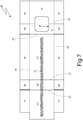
- the inner container 14 is formed by folding a blank 25.
- the blank 25 comprises two longitudinal folding lines 26 and a plurality of transverse folding lines 27 which define, between the two longitudinal folding lines 26, a panel 15' which makes up the upper part of the front wall 15 of the inner container 14, a panel 18' which makes up the upper wall 18 of the inner container 14, a panel 17' which makes up the rear wall 17 of the inner container 14, a panel 19' which makes up the lower wall 19 of the inner container 14, and a panel 15" which makes up the lower part of the front wall 15 of the inner container 14.
- the panel 15' partially overlaps the panel 15" to form the front wall 15 of the inner container 14; as clearly illustrated in Figure 7 , there is an overlapping band in which the lower portion of the panel 15' is resting on top of the upper portion of the panel 15".
- the lower edge of the panel 15' is flush with the upper edge of the panel 15" or, alternatively, the lower edge of the panel 15' is spaced apart from the upper edge of the panel 15".
- the blank 25 comprises a pair of wings 16', which are arranged on opposite sides of the panel 15', are connected to the panel 15' along the two longitudinal folding lines 26 and make up part of the side walls 16 of the inner container 14.
- the blank 25 comprises a pair of wings 16"', which are arranged on opposite sides of the panel 17', are connected to the panel 17' along the two longitudinal folding lines 26, make up part of the side walls 16 of the inner container 14, and overlap the corresponding wings 16' to form part of the side walls 16 of the inner container 14.
- the blank 25 comprises a pair of wings 16", which are arranged on opposite sides of the panel 15", are connected to the panel 15" along the two longitudinal folding lines 26, make up part of the side walls 16 of the inner container 14, and overlap the corresponding wings 16"' to form part of the side walls 16 of the inner container 14.
- the blank 25 comprises a pair of wings 29, which are arranged on opposite sides of the panel 18', are connected to the panel 18' along the two longitudinal folding lines 26 and are folded by 90° relative to the panel 18' to rest against the wings 16"'.
- the blank 25 comprises a pair of wings 30, which are arranged on opposite sides of the panel 19', are connected to the corresponding wings 16"' along a transverse folding line 27 and are folded by 90° relative to the corresponding wings 16"' to rest against the panel 19'.
- the inner container 14 is internally devoid of glue (i.e. no glue is used to connect parts of the inner container 14 to one another) and the inner container 14 is glued to the outer container 2 only by means of permanent glue 31 (i.e. of a glue that dries after its application thus providing a strong and non-separable bond, except by means of a violent and destructive tear).
- permanent glue 31 i.e. of a glue that dries after its application thus providing a strong and non-separable bond, except by means of a violent and destructive tear.
- the permanent glue 31 is arranged at the rear wall 17 of the inner container 14 (i.e.
- the permanent glue 31 may also not be provided (i.e. the inner container 14 is not glued to the outer container 2) or the permanent glue 31 could be applied differently than what illustrated in Figure 7 . It is important to note that preferably the permanent glue 31 (interposed between the inner container 14 and the outer container 2) is initially applied to the blank 24 (i.e. to the outer container 2) and not to the blank 25 (i.e. to the inner container 14).
- the wings 16"' (to which the wings 30 are connected) are folded by 90° relative to the panel 17'.
- the wings 30 are folded by 90° relative to the corresponding wings 16"'.
- the panel 19' (to which the panel 15", provided with the wings 16", is connected) is folded by 90° relative to the panel 17'; in this way the panel 19' rests against the two previously folded wings 30 and the panel 15", provided with the wings 16", is arranged perpendicular to the panel 17'.
- the panel 15" provided with the wings 16" is folded by 90° relative to the panel 19'; in this way the panel 15", provided with the wings 16", is arranged parallel to the panel 17'.
- the panel 18' (provided with the wings 29 and to which the panel 15', provided with the wings 16', is connected) is folded by 90° relative to the panel 17'; in this way the panel 15', provided with the wings 16', is arranged perpendicular to the panel 17'.
- the wings 29 are folded by 90° relative to the panel 18' and against the wings 16"' .
- the panel 15' provided with the wings 16' is folded by 90° relative to the panel 18' and partially above the panel 15"; in this way the panel 15', provided with the wings 16', is arranged parallel to the panel 17'.
- the wings 16' are folded by 90° relative to the panel 15' and against the wings 16"' and, at the same time, the wings 16" are folded by 90° relative to the panel 15" and against the wings 16"' to complete the formation of the inner container 14.
- the wings 30 are arranged on opposite sides of the panel 19', are connected to the panel 19' along the two longitudinal folding lines 26 and are folded by 90° relative to the panel 19' to rest against the wings 16"'.
- the panel 19' (provided with the wings 30 and to which the panel 15", provided with the wings 16", is connected) is folded by 90° relative to the panel 17'; in this way the panel 15", provided with the wings 16" is arranged perpendicular to the panel 17'.
- the wings 30 are folded by 90° relative to the panel 19' and against the corresponding wings 16"'.
- the wings 29 are arranged on opposite sides of the panel 18', are connected to the corresponding wings 16"' along a transverse folding line 27, and are folded by 90° relative to the corresponding wings 16"' so as to rest against the panel 18' (in this embodiment the wings 29 are much smaller so as not to interfere with the pull-out opening 20 when they are folded against the panel 18').
- number 32 denotes, as a whole, a packer machine which is adapted to produce the pack 1 of cigarettes described above.
- the packer machine 32 comprises a forming unit 33 (known and only schematically illustrated in Figure 19 ) in which the groups 23 of cigarettes are formed in succession, a wrapping unit 34 in which a blank 25 is folded around each group 23 of cigarettes to form the corresponding inner container 14, and a wrapping unit 35, in which a blank 24 is folded around each inner container 14 to form the corresponding outer container 2 provided with the hinged lid 4.
- a feeding unit 36 is coupled to the wrapping unit 34, which feeds the blanks 25 in succession, while a feeding unit 37 is coupled to the wrapping unit 35, which feeds the blanks 24 in succession.
- the forming unit 33 comprises a hopper 38 provided with a plurality of outlet openings for feeding the groups 23 of cigarettes, a forming conveyor 39 provided with trains of pockets, each of which receives a group 23 of cigarettes from the hopper 38 and a transfer drum 40 which is mounted so as to rotate in a continuous manner and cyclically withdraws the groups 23 of cigarettes from the pockets of the forming conveyor 39 to transfer the groups 23 of cigarettes to the wrapping unit 34.
- the wrapping unit 34 comprises a transfer drum 41 which is mounted so as to rotate in a continuous manner about a horizontal rotation axis 42 (perpendicular to the plane of Figure 16 ) and is provided with a plurality of transfer pockets 43 (only one of which is illustrated in the attached Figures for clarity), each of which is adapted to receive and hold a group 23 of cigarettes.
- the rotation of the transfer drum 41 about the rotation axis 42 carries each transfer pocket 43 through a transfer station S1 in which the transfer pocket 43 receives a group 23 of cigarettes from the transfer drum 40 of the forming unit 33 and a transfer station S2, in which the transfer pocket 43 releases the group 23 of cigarettes.
- the wrapping unit 34 comprises a wrapping drum 44 which is mounted so as to rotate in a continuous manner about a horizontal rotation axis 45 (parallel to the rotation axis 42) and is provided with a plurality of wrapping pockets 46 (only one of which is illustrated in the attached Figures for clarity), each of which is adapted to receive and hold a blank 25 and subsequently a group 23 of cigarettes.
- the rotation of the wrapping drum 44 about the rotation axis 45 carries each wrapping pocket 46 through a feeding station S3 in which the wrapping pocket 46 receives a blank 25 from the feeding unit 36, subsequently through the transfer station S2 in which the wrapping pocket 46 receives a group 23 of cigarettes from the transfer drum 41, and finally through a transfer station S4 in which the wrapping pocket 46 releases the group 23 of cigarettes coupled to the blank 25.
- Each wrapping pocket 46 is provided with folding devices (better described in the following) which perform all the folding of the blank 25 around the group 23 of cigarettes.
- the wrapping unit 34 comprises a wrapping drum 47 which is mounted so as to rotate in a continuous manner about a horizontal rotation axis 48 (parallel to the rotation axis 45) and is provided with a plurality of wrapping pockets 49 (only one of which is illustrated in the attached Figures for clarity), each of which is adapted to receive and hold an inner container 14 (i.e. a group 23 of cigarettes completely wrapped in a blank 25).
- the rotation of the wrapping drum 47 about the rotation axis 48 carries each wrapping pocket 49 through the transfer station S4 in which the wrapping pocket 49 receives an inner container 14 from the wrapping drum 44 (the folding of the blank 25 around the group 23 of cigarettes is completed in the transfer station S4 wherein the entry of the wrapping drum 47 into the wrapping pocket 49 causes the folding by 90° of the wings 16' and of the wings 16" against the wings 16"') and subsequently through a transfer station S5 in which the wrapping pocket 49 releases the inner container 14.
- the wrapping unit 35 comprises a wrapping drum 50 which is mounted so as to rotate in a continuous manner about a horizontal rotation axis 51 (parallel to the rotation axis 48) and is provided with a plurality of wrapping pockets 52 (only one of which is illustrated in the attached Figures for clarity), each of which is adapted to receive and hold a blank 24 and therefore an inner container 14.
- the rotation of the wrapping drum 50 about the rotation axis 51 carries each wrapping pocket 52 through a feeding station S6, in which the wrapping pocket 52 receives a blank 24 from the feeding unit 37, thereafter through the transfer station S5, in which the wrapping pocket 52 receives an inner container 14 from the wrapping drum 47, and finally through a transfer station S7, in which the wrapping pocket 52 releases the inner container 14 coupled to the blank 24.
- Each wrapping pocket 52 is provided with folding devices which fold the blank 24 around the inner container 14. Moreover, around the wrapping drum 44 and between the transfer station S5 and the transfer station S7 further folding devices (external and independent of the wrapping drum 50 and schematically illustrated only with a dashed line) are arranged, which perform the folding of the blank 24 around the inner container 14.
- the wrapping unit 35 comprises a wrapping drum 53 (illustrated only in Figure 19 ) which is mounted so as to rotate in a continuous manner about a horizontal rotation axis (parallel to the rotation axis 51) and is provided with a plurality of wrapping pockets (only one of which is illustrated in Figure 19 for clarity), each of which is adapted to receive and hold a pack 1 of cigarettes (i.e. an inner container 14 completely wrapped in a blank 24).
- a wrapping drum 53 illustrated only in Figure 19
- the wrapping unit 35 comprises a wrapping drum 53 (illustrated only in Figure 19 ) which is mounted so as to rotate in a continuous manner about a horizontal rotation axis (parallel to the rotation axis 51) and is provided with a plurality of wrapping pockets (only one of which is illustrated in Figure 19 for clarity), each of which is adapted to receive and hold a pack 1 of cigarettes (i.e. an inner container 14 completely wrapped in a blank 24).
- the rotation of the wrapping drum 53 about its rotation axis carries each wrapping pocket through the transfer station S7 in which the wrapping pocket receives a pack 1 of cigarettes from the wrapping drum 50 (the folding of the blank 24 around the inner container 14 is completed in the transfer station S7 by folding the wings 9' and 13' by 90° against the previously folded wings 9" and 13").
- the packs 1 of cigarettes are transferred to a vertical outlet conveyor and then to a subsequent horizontal outlet conveyor.
- the feeding unit 36 comprises a feeding drum 54 which is mounted so as to rotate in a continuous manner about a horizontal rotation axis 55 (parallel to the rotation axis 45) and is provided with a plurality of feeding heads 56 (only one of which is illustrated in the attached Figures for clarity), each of which is adapted to receive and hold a blank 25.
- the rotation of the feeding drum 54 about the rotation axis 55 carries each feeding head 56 through a pick-up station S8 in which the feeding head 56 picks-up a blank 25 from a horizontal stack of blanks 25 and through the feeding station S3, in which the feeding head 56 releases the blank 25 to a wrapping pocket 46 of the wrapping drum 44.
- the feeding unit 36 comprises a horizontal feeding conveyor 57 which supports the horizontal stack of blanks 25 thus feeding the horizontal stack towards the pick-up station S8.
- the feeding unit 36 comprises a horizontal feeding conveyor 58 which supports a series of bundles 59 of blanks 25 and feeds the bundles 59 of blanks 25 to a vertical hopper 60 having an upper inlet opening in which the bundles 59 of blanks 25 are inserted in succession and a lower outlet opening from which the individual blanks 25 are cyclically extracted.
- a transfer drum 61 is arranged downstream of the hopper 60, which is mounted so as to rotate in a continuous manner about a horizontal rotation axis and is provided with a plurality of transfer heads (only one of which is illustrated in Figure 19 for clarity), each of which is adapted to receive and hold a blank 25.
- the rotation of the transfer drum 61 around the rotation axis carries each transfer head to pick up an individual blank 25 from the outlet opening of the hopper 60 and then to release the blank 25 to a tab-sticking unit 62 in which a corresponding closing tab 21 is applied to each blank 25.
- the tab-sticking unit 62 comprises a tab-sticking drum 63 which receives the blanks 25 from the transfer drum 61, a tab-sticking device 64 which is adapted to stick the closing tabs 21 onto the blanks 25 carried by the tab-sticking drum 63, a further tab-sticking drum 65, which receive the blanks 25 from the tab-sticking drum 63 by the interposition of a transfer drum 66, and a further tab-sticking device 67, which is adapted to stick the closing tabs 21 on the blanks 25 carried by the tab-sticking drum 65.
- the two tab-sticking devices 64 can be operated alternatively (while a tab-sticking device 64 works the other tab-sticking device 64 is still, for example to allow cleaning, adjustment or replacement manoeuvres of the belt containing the closing tabs 23) or the two tab-sticking devices 64 can be operated together (obviously at a half operating speed because each tab-sticking device 64 applies a closing tab 21 to every two blanks 25).
- the tab-sticking unit comprises only the tab-sticking device 67 and the tab-sticking drum 65 (i.e. the tab-sticking device 64, the tab-sticking drum 63, and the transfer drum 66 are not provided).
- each closing tab 21 is applied to the corresponding blank 25 when the blank 25 is completely extended; in this way it is possible to stick each closing tab 21 to the corresponding blank 25 with a very high precision (not having to "follow" three-dimensional shapes during the application) and with an optimal adhesion (when the blank 25 is completely extended, it is simple to exert a high pressure between the closing tab 21 and the blank 25 to favour optimal adhesion of the closing tab 21 to the blank 25).
- the tab-sticking unit 62 comprises a control and rejection device 68, which is adapted to optically detect (for example by means of a digital video camera) an image of each blank 25 at least at the closing tab 21 to check whether the closing tab 21 is present, has been correctly applied (i.e. in the desired position and without folds or anomalous orientations) and is free of defects; in case of missing, incorrectly arranged or defective closing tabs 21, the control and rejection device 68 rejects the corresponding blanks 25, i.e. extracts the corresponding blanks 25 from the production flow, directing the rejected blanks 25 to a collecting container.
- a control and rejection device 68 which is adapted to optically detect (for example by means of a digital video camera) an image of each blank 25 at least at the closing tab 21 to check whether the closing tab 21 is present, has been correctly applied (i.e. in the desired position and without folds or anomalous orientations) and is free of defects; in case of missing, incorrectly arranged or defective closing tabs 21, the control and rejection device
- control and rejection device 68 could control the blanks 25 only at the closing tab 21 or could also control the blanks 25 in their entirety.
- the control and rejection device 68 is coupled to the tab-sticking drum 65 downstream of the tab-sticking device 67; according to other embodiments not illustrated, the control and rejection device 68 could be arranged in a different position (again downstream of the tab-sticking device 67).
- controlling each blank 25 before folding the blank 25 around the corresponding group 23 of cigarettes makes it possible to reject only the defective 25 blanks without having, at the same time, to also reject groups 23 of cigarettes (being free of defects) only because they are coupled with defective blanks 25.
- controlling each blank 25 before folding the blank 25 around the corresponding group 23 of cigarettes allows to significantly reduce the number of cigarettes being rejected.
- the feeding unit 36 comprises a transfer device 69 which receives the blanks 25 (provided with the closing tabs 21) from the tab-sticking drum 62 of the tab-sticking unit 62, collects the blanks 25 forming corresponding stacks and then cyclically transfers the stacks of blanks 25 on the feeding conveyor 57 to replenish the horizontal stack fed by feeding conveyor 57 towards the pick-up station S8.
- the transfer device 69 comprises a stacking chamber which is hinged to rotate about a horizontal rotation axis between a receiving position (illustrated in Figure 19 ) in which the blanks 25 are cyclically inserted on the inside of the stacking chamber by the tab-sticking drum 65 to form a stack and a release position (not illustrated) in which a stack of blanks 25 is extracted from the stacking chamber to be transferred to the feeding conveyor 57.
- the transfer device 69 comprises a horizontal stacking chamber which is vertically movable between a receiving position, in which the blanks 25 are cyclically inserted inside the stacking chamber to form a stack, and a release position, in which a stack of blanks 25 is extracted from the stacking chamber to be transferred to the feeding conveyor 57; preferably, in the receiving position, the stacking chamber is arranged above the feeding conveyor 57 and in the release position the stacking chamber is vertically aligned with the feeding conveyor 57 (i.e. the stacking chamber is lowered with a vertical movement to move from the receiving position to the release position).
- the transfer device 69 comprises a transfer drum (totally similar to the transfer drum 61) which cyclically picks-up the individual blanks 25 from the tab-sticking drum 65 and deposits the individual blanks 25 in the stacking chamber.
- the feeding unit 37 comprises a feeding drum 70 which is mounted so as to rotate in a continuous manner about a horizontal rotation axis 71 (parallel to the rotation axis 51) and is provided with a plurality of feeding heads 72 (only one of which is illustrated in the attached Figures for clarity), each of which is adapted to receive and hold a blank 24.
- the rotation of the feeding drum 70 about the rotation axis 71 carries each feeding head 72 through a pick-up station S9, in which the feeding head 72 picks-up a blank 24 from the pocket of a horizontal stack of blanks 24 and through the feeding station S6, in which the feeding head 72 transfers the blank 24 to a wrapping pocket 52 of a wrapping drum 50.
- the feeding unit 37 comprises a horizontal feeding conveyor 73 which supports the horizontal stack of blanks 24, feeding the horizontal stack towards the pick-up station S9.
- the feeding unit 37 comprises a horizontal feeding conveyor 74 which supports a series of bundles 75 of blanks 24 and feeds the bundles 75 of blanks 24 to a transfer device 76 which cyclically transfers (by rotation) the bundles 75 of blanks 24 on the feeding conveyor 73 to replenish the horizontal stack fed by the feeding conveyor 73 towards the pick-up station S9.
- the wrapping unit 35 comprises a gluing device 77 (for example by spraying) which deposits the permanent glue 31 (for example quick-setting hot glue) on the panel 8' of the blank 24 so that the permanent glue 31 produces a permanent adhesion of the rear wall 8 of the outer container 2 to the rear wall 17 of the inner container 14 when the inner container 14 rests against the panel 8' of the blank 24 in the transfer station S5.
- the permanent glue 31 for example quick-setting hot glue
- the inner container 14 is internally devoid of glue (i.e. no glue is used to connect parts of the inner container 14 together) and therefore in the wrapping unit 34 (i.e. at the wrapping drum 44 and at the wrapping drum 47) no gluing devices are provided as no glue is applied to the blank 25.
- the wrapping unit 35 only comprises the gluing device 77 which, in addition to applying the permanent glue 31 on each blank 24 for gluing the inner container 14 to the outer container 2, it also applies, to each blank 24 (in particular on the wings 9' or 9" and 13' or 13" of each blank 24), permanent glue which stabilizes the shape of the outer container 2 and of the lid 4.
- the gluing device 77 only applies the permanent glue which stabilizes the shape of the outer container 2 and of the lid 4 (i.e. does not apply the permanent glue 31 for gluing the inner container 14 to the outer container 2 and therefore the inner container 14 is not glued to the outer container 2).
- the gluing device 77 only applies the permanent glue 31 for gluing the inner container 14 to the outer container 2 and a further gluing device is provided (separate and independent of the gluing device 77) which is arranged around the wrapping drum 50 near the transfer station S7 and is adapted to apply, on the blank 24, the permanent glue, which stabilizes the shape of the outer container 2 and of the lid 4.
- the folding of the blank 24 around the inner container 14 is completed in the transfer station S7 by folding the wings 9' and 13' by 90° against the previously folded wings 9" and 13"; consequently, the gluing (i.e. the application of glue) on the wings 9' or 9" and 13' or 13" of the blank 24 takes place immediately before the folding of the wings 9' and 13' against the wings 9" and 13" (i.e. immediately before the transfer station S7).
- each wrapping pocket 46 comprises a main body 78 that is rigidly mounted on a support head 79, which is connected to the wrapping drum 44 in a rotary manner so as to rotate about a rotation axis 80 (parallel to the rotation axis 45 of the wrapping drum 44) under the control of a cam actuating system.
- a base 81 is mounted on the main body 78 of each wrapping pocket 46, which is arranged parallel to the rotation axis 45 of the wrapping drum 44 and is provided with suction to hold a corresponding blank 25 by way of suction; in particular, the base 81 has approximately the size of the panel 17' of the blank 25 and in use engages (by suction) the panel 17' of the blank 25.
- the base 81 is mounted on the main body 78 in a radially sliding manner, i.e. it is adapted to slide (under the control of a cam actuating system) relative to the main body 78 along a radial sliding direction 82 (i.e. perpendicular to the rotation axis 45 of the wrapping drum 44) between a retracted position (not illustrated) and an extracted position (illustrated in Figures 23 and 24 ).
- each wrapping pocket 46 On the main body 78 of each wrapping pocket 46, two side walls 83 are mounted, which are arranged on opposite sides of the base 81 and are hinged to the main body 78 to rotate (under the control of a cam actuating system) about two corresponding rotation axes parallel to the rotation axis 45 of the wrapping drum 44 between a raised position (illustrated in Figures 21 and 22 ), wherein the two side walls 83 are perpendicular to the base 81 and a lowered position (not illustrated), wherein the two side walls 83 are parallel to the base 81 (or slightly inclined relative to the base 81).
- each wrapping pocket 46 On the main body 78 of each wrapping pocket 46, two containment plates 84 are mounted, which are orientated perpendicularly to the two side walls 83 and are hinged to the main body 78 to rotate (under the control of a cam actuating system) around two corresponding rotation axes perpendicular to the rotation axis 45 of the wrapping drum 44 between a rest position (illustrated in Figures 21 and 22 ) wherein the two containment plates 84 are relatively far away from the base 81 and an operative position (not illustrated) wherein the two containment plates 84 are arranged at the base 81.
- each containment plate 84 is hinged to the main body 78 by means of a "U"-shaped arm which rigidly supports the containment plate 84 at one end and is hinged to the main body 78 at the opposite end.
- each transfer pocket 43 of the transfer drum 41 is completely identical to the wrapping pockets 46 of the wrapping drum 44 (and therefore, in fact, also the transfer drum 41 is identical to the wrapping drum 44, although having a different role, as the transfer drum 41 limits the movement of the groups 23 of cigarettes from the transfer station S1 to the transfer station S2, whereas in the wrapping drum 44, during the movement of the groups 23 of cigarettes from the transfer station S2 to the transfer station S3, the folding of the blanks 25 around the groups 23 of cigarettes is performed).
- This design choice allows to lower the production costs of the packer machine 32 as it allows to considerably reduce the number of different pieces of which the packer machine 32 is formed.
- each wrapping pocket 49 of the wrapping drum 47 is completely identical to the wrapping pockets 46 of the wrapping drum 44, while each wrapping pocket 52 of the wrapping drum 50 is very similar but not completely identical to the wrapping pockets 46 of the wrapping drum 44, since around the wrapping drum 50 the blanks 24 are folded, which are different from the blanks 25 that are folded around the wrapping drum 44.
- each wrapping pocket 46 the two side walls 83 form folding devices (carried by the wrapping pocket 46), which perform the folding of the wings 16"' relative to the panel 17' and the two containment plates 84 form the folding devices (carried by the wrapping pocket 46), which perform the folding of the panels 19' e 18' relative to the panel 17' and the folding of the panels 15' e 15" relative to the panels 18' e 19'.
- the base 81 of the wrapping pocket 46 when a blank 25 is fed (at the feeding station S3) to a wrapping pocket 46, the base 81 of the wrapping pocket 46 is in the extracted position (also illustrated in figure 23 wherein the feeding of the blank 25 to the wrapping pocket 46 is shown) so as to receive the blank 25 (in particular the base 81 rests against the panel 17' of the blank 25) and to hold the blank 25 by suction.
- the wrapping pocket 46 Once the wrapping pocket 46 has picked-up a blank 25 in the feeding station S3, the wrapping pocket 46 moves towards the transfer station S2 in which it also receives the group 23 of cigarettes from a transfer pocket 43 of the transfer drum 41 (as illustrated in Figure 24 ).
- the bases 81 of both the pockets 43 and 46 are in the extracted position so that the group 23 of cigarettes carried by the transfer pocket 43 of the transfer drum 41 can be released to the wrapping pocket 46 of the wrapping drum 44 (there is a moment, illustrated in Figure 24 , wherein the group 23 of cigarettes is engaged by both bases 81).
- the side walls 83 Upstream of the transfer station S2 and in the transfer pocket 43 of transfer drum 41, the side walls 83 (not illustrated for clarity in Figure 24 ) are in the raised position and the containment plates 84 are in the operative position to hold the group 23 of cigarettes thus maintaining the shape of the group 23 of cigarettes unaltered; in the feeding station S3 and in the transfer pocket 43 of the transfer drum 41, the side walls 83 (not illustrated for clarity in Figure 24 ) are moved to the lowered position and the containment plates 84 are moved to the rest position to release the group 23 of cigarettes and thus allowing the group 23 of cigarettes to be transferred into the wrapping pocket 46 of the wrapping drum 44.
- the base 81 of the wrapping pocket 46 of the wrapping drum 44 In the transfer station S2 and after the group 23 of cigarettes has been placed resting against (with the interposition of the blank 25) the base 81 of the wrapping pocket 46 of the wrapping drum 44, the base 81 itself moves from the extracted position to the retracted position and, at the same time, the side walls 83 move from the lowered position to the raised position to fold the two wings 16"' of the blank 25 by 90° relative to the panel 17' and against the group 23 of cigarettes; in other words, the first folding of each blank 25 (as illustrated in Figures 8 and 16 ) takes place in the transfer station S2 and around the group 23 of cigarettes, which rests against the panel 17', by means of the two side walls 83 which act as folding devices.
- the group 23 of cigarettes is rested against the panel 17' of the blank 25 when the blank 25 is still (substantially) flat; in this way the group 23 of cigarettes is not subjected to anomalous stresses (since it cannot "bump” against already folded parts of the blank 25) and can be placed, with great precision, resting against the blank 25 itself.
- the wrapping drum 44 is provided with folding devices (mounted on the wrapping pockets 46) which, between the transfer station S2 and the transfer station S4 and for each blank 25, fold the panel 19' by 90° relative to the panel 17' (as illustrated in Figures 10 and 17 ), fold the panel 15" by 90° relative to the panel 19' (as illustrated in Figure 11 ), fold the panel 18' by 90° relative to the panel 17' (as illustrated in Figure 12 ), and fold the panel 15' by 90° relative to the panel 18' (as illustrated in Figure 14 ); these folding devices are the two containment plates 84 of each wrapping pocket 46 which, by moving from the rest position to the operative position, perform all the folding described above, i.e. they perform the folding of the panels 19' and 18' relative to the panel 17' and the subsequent folding of the panels 15' and 15" relative to panels 18' and 19'.
- the wings 16' and the wings 16" are folded by 90° and against the wings 16"' completing the formation of the inner container 14 in the transfer station S4 during the passage of the inner container 14 from the wrapping pocket 46 of the wrapping drum 44 to the wrapping pocket 49 of the wrapping drum 47.
- the wrapping drum 44 is provided with folding devices (mounted on the wrapping pockets 46) which, between the transfer station S2 and the transfer station S4 and for each blank 25, fold the wings 29 by 90° relative to the panel 18' (as illustrated in Figure 13 ) and against the wings 16"' after having folded the panel 18' by 90° relative to the panel 17' (as illustrated in Figure 12 ) and before folding the panel 15' by 90° relative to the panel 18' (as illustrated in Figure 14 ); according to a preferred embodiment, these folding devices (not illustrated) are mounted (hinged) on a containment plate 84 of each wrapping pocket 46 or, alternatively, they are mounted (hinged) on the support head 79 of each wrapping pocket 46.
- the wrapping drum 44 is provided with folding devices (mounted on the wrapping pockets 46) which, between the feeding station S3 and the transfer station S4 (preferably the feeding station S3 and the transfer station S2) and for each blank 25, fold the wings 30 by 90° relative to the corresponding wings 16"' (as illustrated in Figure 9 ) after having folded the wings 16" by 90° relative to the panel 17' (as illustrated in Figure 8 ) and before folding the panel 19' by 90° relative to the panel 17' (as illustrated in Figure 10 ); according to a preferred embodiment, these folding devices (not illustrated) are mounted (hinged) on both side walls 83 of each wrapping pocket 46.
- the wrapping drum 44 is provided with folding devices (mounted on the wrapping pockets 46) which, between the transfer station S2 and the transfer station S4, fold by 90° the wings 30 relative to the panel 19' and against the wings 16"' (as illustrated in Figure 18 ) after having folded the panel 19' by 90° relative to the panel 17' (as illustrated in Figure 17 ) and before folding the panel 15" by 90° relative to panel 19' (as illustrated in Figure 11 ); according to a preferred embodiment, these folding devices (not illustrated) are mounted (hinged) on a containment plate 84 of each wrapping pocket 46 or, alternatively, they are mounted (hinged) on the support head 79 of each wrapping pocket 46.
- the rear wall 17 is formed by a single panel (the panel 17' of the blank 25) while the front wall 15 is formed by two panels (the panels 15' and 15" of the blank 25) arranged at the opposite ends of the blank 25.
- the front wall 15 is formed by a single panel (the panel 15' of the blank 25) while the rear wall 17 is formed by two panels (the panels 17' and 17" of the blank 25) arranged at the opposite ends of the blank 25; in other words, in this embodiment in the blank 25 the position/configuration of the rear wall 17 is exchanged with the position/configuration of the front wall 15.
- the panel 15' of the blank 25 rests against the base wall 81 of the corresponding wrapping pocket 46, and therefore in the transfer station S2 the group 23 of cigarettes rests against the panel 15' of the blank 25.
- the packer machine 32 described above has numerous advantages.
- the packer machine 32 described above allows to avoid the application of glue inside the inner containers 14 (i.e. in close proximity to the groups 23 of cigarettes) thus avoiding the risk of contaminating the cigarettes with traces of glue (both by direct contact of the cigarettes with the glue, and by absorption, by the cigarettes, of volatile substances released by the glue).
- the packer machine 32 described above can operate with continuous motion (i.e. a motion devoid of stopping steps wherein the various moving parts move with a constant speed) which substantially reduces the mechanical stresses to which the cigarettes are subjected thus allowing to operate at a high hourly productivity (i.e. a high number of packs 1 of cigarettes produced per time unit) while maintaining, at the same time, an optimal production quality.
- continuous motion i.e. a motion devoid of stopping steps wherein the various moving parts move with a constant speed
- a high hourly productivity i.e. a high number of packs 1 of cigarettes produced per time unit
- the packer machine 32 described above is compact and has an optimal accessibility to all its components; in fact, an operator who is in front of the packer machine 32 is able to reach, by hand, all the active parts of the packer machine 32 in a simple, fast and ergonomic manner.
- the embodiment illustrated in the attached figures refers to the production of a pack of cigarettes, but the present invention can also be applied, without substantial modifications, to the production of any other type of pack of smoking articles (for example a pack of cigars, a pack of electronic cigarettes of the liquid vaporization type, a new generation pack of cigarettes without tobacco combustion).
- any other type of pack of smoking articles for example a pack of cigars, a pack of electronic cigarettes of the liquid vaporization type, a new generation pack of cigarettes without tobacco combustion.
- the packer machine 32 described above can be easily modified to produce a standard pack of cigarettes (i.e. wherein the inner container 14 is replaced by a standard collar having only three walls, i.e. a front wall and two opposite side walls) simply by disabling (and possibly disassembling or removing) the feeding unit 36 which is replaced by a standard feeding unit, which feeds the standard collars at the transfer station S4. Accordingly, the packer machine 32 described above is very flexible as it can easily be adapted to produce different types of packs of cigarettes.
Landscapes
- Engineering & Computer Science (AREA)
- Mechanical Engineering (AREA)
- Wrapping Of Specific Fragile Articles (AREA)
- Packaging Of Annular Or Rod-Shaped Articles, Wearing Apparel, Cassettes, Or The Like (AREA)
Abstract
Description
- This Patent application claims priority from Italian Patent Application No.
102017000134278 filed on November 23, 2017 - The present invention relates to a packer machine and to a wrapping method to produce a pack of smoking articles provided with two rigid containers one inside the other.
- The present invention finds advantageous application in producing a pack of cigarettes containing a group of cigarettes, to which the following disclosure will make explicit reference without thereby losing generality.
- In patent
US8123030B2 a pack of cigarettes has been proposed, comprising a group of cigarettes, a rigid inner container having a through pull-out opening through which the cigarettes can be withdrawn, and a rigid outer container which contains the inner container and is provided with a hinged lid; preferably, a closing tab is coupled to the inner container, which is glued, by means of re-stick glue, to the inner container to cover the pull-out opening. - In patent
US8123030B2 a packer machine has also been proposed, which produces the pack of cigarettes described above and comprises: a first wrapping drum having a vertical rotation axis (i.e. arranged horizontally), which receives a first blank and then the group of cigarettes and folds the first blank around the group of cigarettes to form the inner container, a first gluing unit that is arranged downstream of the first wrapping drum and applies glue to opposite side walls of the first container to stabilize the shape of the first container itself, a pair of first drying drums arranged downstream of the first gluing unit to allow the glue to set, a second wrapping drum having a vertical rotation axis (i.e. arranged horizontally) which receives a second blank and then the inner container and folds the second blank around the inner container to form the outer container (thus completing the formation of the pack of cigarettes), a second gluing unit which is arranged downstream of the second wrapping drum and applies glue to opposite side walls of the second container to stabilize the shape of the second container itself, and a pair of second drying drums arranged downstream of the second gluing unit to allow the glue to set. - However, the packer machine described in patent
US8123030B2 is very bulky (i.e. it occupies a large surface area) and above all has many parts that are hard to reach (i.e. an operator cannot reach, by hand, many parts of the packer machine while standing in front of the packer machine, but in order to reach many parts of the packer machine by hand one must somehow "enter" the packer machine by making demanding and tiring "contortions"). Consequently, assembly and above all maintenance and periodic cleaning of the packer machine described in patentUS8123030B2 are extremely laborious and particularly long (with a consequent extremely long maintenance and cleaning down-time of the machine and therefore clearly detrimental to the average productivity of the packer machine in the long run). - Moreover, the packer machine described in the patent
US8123030B2 is adapted to operate only with an intermittent motion (i.e. a motion that cyclically alternates stopping steps and motion steps) and then subjects the mechanics to continuous accelerations/decelerations which do not allow a high hourly productivity to be obtained (i.e. a large number of packs of cigarettes produced per time unit) while maintaining an optimal production quality. - The object of the present invention is to provide a packer machine and a wrapping method to produce a pack of smoking articles provided with two rigid containers one inside the other, which packer machine and wrapping method are free from the drawbacks described above and are, at the same time, easy and inexpensive to produce.
- According to the present invention, a packer machine and a wrapping method are provided to produce a pack of smoking articles provided with two rigid containers one inside the other, according to what is claimed in the attached claims.
- The claims describe preferred embodiments of the present invention forming an integral part of the present disclosure.
- The present invention will now be described with reference to the attached drawings, which illustrate an example of non-limiting embodiment, wherein:
-
Figure 1 is a front perspective view and in a closed configuration of a pack of cigarettes provided with two rigid containers one inside the other; -
Figure 2 is a rear perspective view of the pack of cigarettes ofFigure 1 in a closed configuration; -
Figure 3 is a front perspective view of the pack of cigarettes ofFigure 1 in an open configuration; -
Figure 4 is a front perspective view of an inner container of the pack ofFigure 1 ; -
Figure 5 is a perspective view of a group of cigarettes contained in the inner container ofFigure 4 ; -
Figure 6 is a plan view of a blank used to produce an outer container provided with a hinged lid of the pack of cigarettes ofFigure 1 ; -
Figure 7 is a plan view of a blank used to produce the inner container ofFigure 4 ; -
Figures 8-14 illustrate a perspective view of the folding of the blank ofFigure 7 to produce the inner container ofFigure 4 ; -
Figure 15 is a plan view of an alternative of the blank ofFigure 7 ; -
Figures 16-18 illustrates a perspective view of the folding of the blank ofFigure 15 to produce the inner container ofFigure 4 ; -
Figure 19 is a front view of a packer machine which manufactures the pack of cigarettes ofFigure 1 and is produced according to the present invention; -
Figure 20 is an enlarged view of a portion of the packer machine ofFigure 19 ; -
Figures 21 and22 are two different perspective views and with the removal of parts for clarity of a wrapping pocket of a wrapping drum of the packer machine ofFigure 19 ; -
Figure 23 is a perspective view and with the removal of parts for clarity of the feeding of the blank ofFigure 7 in the wrapping pocket ofFigures 21 and22 ; -
Figure 24 is a perspective view and with the removal of parts for clarity of the transfer of a group of cigarettes into the wrapping pocket ofFigures 21 and22 ; and -
Figure 25 is a plan view of a further alternative of the blank ofFigure 7 . - In
Figures 1, 2 and3 number 1 denotes, as a whole, a rigid pack of cigarettes. Thepack 1 of cigarettes comprises anouter container 2 made of a cup-shaped rigid cardboard or paperboard. - The
outer container 2 has an openupper end 3 and is provided with alid 4, which is cup-shaped and is hinged to theouter container 2 along a hinge 5 (illustrated inFigure 2 ) to rotate relative to theouter container 2, between an open position (illustrated inFigure 3 ) and a closed position (illustrated inFigures 1 and 2 ) of the openupper end 3. Theouter container 2 has a substantially rectangular parallelepiped shape orientated in a prevalently vertical development direction, is cup-shaped, and has the openupper end 3, alower wall 6 opposite the openupper end 3, a front wall 7 and a rear wall 8 (where thehinge 5 is obtained) parallel and opposite to one another, and twoside walls 9 parallel and opposite to each other. Between the front 7, rear 8 andside 9 walls of theouter container 2, four longitudinal edges are defined, whereas between thewalls lower wall 6 of theouter container 2, four transverse edges are defined. - The
lid 4 has a substantially rectangular parallelepiped shape, is cup-shaped, and has an open lower end (facing the openupper end 3 of theouter container 2 when thelid 4 is in the closed position), an upper wall 10 (which is parallel and opposite to thelower wall 6 of theouter container 2 when thelid 4 is in the closed position), a front wall 11 (which is parallel to and aligned with the front wall 7 of theouter container 2 when thelid 4 is in the closed position) a rear wall 12 (which is parallel to and aligned with therear wall 8 of theouter container 2 when thelid 4 is in the closed position and is hinged to therear wall 8 of theouter container 2 along the hinge 5), and twoside walls 13 parallel and opposite to each other (which are parallel and aligned, in particular coplanar and adjacent, to theside walls 9 of theouter container 2 when thelid 4 is in the closed position). Between thefront 11, rear 12 andside 13 walls of thelid 4, four longitudinal edges are defined, whereas between thewalls upper wall 10 of thelid 4, four transverse edges are defined. The longitudinal edges and transverse edges of thelid 4 are parallel to and aligned with the corresponding longitudinal and transverse edges of theouter container 2 when thelid 4 is in the closed position. - As illustrated in
Figures 3 and4 , thepack 1 of cigarettes comprises aninner container 14, which is fixed (normally by gluing) to the inside of theouter container 2 to partially protrude to the outside of the openupper end 3 and to engage a corresponding inner surface of thelid 4 when thelid 4 itself is arranged in said closed position. Theinner container 14 comprises afront wall 15, which is parallel to and rests against the front wall 7 of thecontainer 2, twoside walls 16 which are folded by 90° relative to thefront wall 15 and are parallel to and rest against theside walls 9 of thecontainer 2, arear wall 17 which is folded by 90° relative to theside walls 16, is parallel to thefront wall 15 and is parallel to, rests against and is glued to therear wall 8 of thecontainer 2, anupper wall 18 which is perpendicular to thewalls lower wall 19 which is parallel and opposite to theupper wall 18, is perpendicular to thewalls lower wall 6 of thecontainer 2. - The
inner container 14 also has the function of keeping thelid 4 in the closed position with a given force to avoid undesired openings of thelid 4; said "locking" function of thelid 4 in the closed position is carried out due to the fact that when thelid 4 is in the closed position theinner container 14 partially protrudes from the open end of thecontainer 2 and thus engages a corresponding inner surface of the lid 4: in this way, to open thelid 4 it is necessary to elastically and slightly deform thelid 4 and/or theinner container 14 and therefore it is necessary to apply a given force to thelid 4 to open thelid 4. - The
inner container 14 has a pull-outopening 20 which is arranged at the centre and involves a portion of thefront wall 15 of theinner container 14 and a portion of theupper wall 18 of theinner container 14. The pull-outopening 20 is formed by making a closed-shaped through incision through theinner container 14 which internally delimits a disposable portion of theinner container 14 which is removed, so as to leave a hole (which forms the extraction opening 20). - According to what is illustrated in
Figure 3 , the extraction opening 20 of theinner container 14 is normally closed by areusable closing tab 21 which is fixed to theinner container 14 by means of the re-stick glue which is arranged around the pull-out opening 20 to allow theclosing tab 21 to be (i.e. at each opening of thepack 1 of cigarettes) partially separated from theinner container 14 several times and then fixed again to the inner container 14 (at each closing of thepack 1 of cigarettes). In other words, the re-stick glue is a glue that does not dry after its application and therefore allows the separation and subsequent re-adhesion of theclosing tab 21 to the underlyinginner container 14 to be repeated several times. - The
closing tab 21 is provided with a connectingflap 22, which is glued in a permanent and non-separable manner to the inner surface of thefront wall 11 of thelid 4 by means of the permanent glue 26 (illustrated inFigure 8 ) which is applied to theouter surface 27 of the closing tab 21 (i.e. to the surface of theclosing tab 21 facing outwards, i.e. from the opposite wall of the inner container 14). In this way, by opening or closing thelid 4, theclosing tab 21 is simultaneously opened and closed as well. - In the (non-limiting) embodiment illustrated in the attached Figures, the outer surface of the connecting
flap 22 of theclosing tab 21 is glued in a permanent and not separable manner to the inner surface of thefront wall 11 of thelid 4 by permanent glue so that, by opening and closing thelid 4, theclosing tab 21 is simultaneously and automatically opened and closed as well. - As illustrated in
Figure 3 , agroup 23 of cigarettes is arranged (illustrated in its entirety inFigure 5 ) inside thecontainer 14. According to the embodiment illustrated in the attached Figures, thegroup 23 of cigarettes is devoid of inner wrap and is in direct contact with theinner container 14; i.e. thegroup 23 of cigarettes is "naked" and therefore it is completely devoid of an inner wrap that wraps the same and, is inserted into theinner container 14 exactly as illustrated inFigure 5 . According to a different embodiment not illustrated, thegroup 23 of cigarettes is wrapped in an inner wrap that is cup-shaped, leaving the upper part of the cigarettes completely in sight (i.e. the filters of the cigarettes), and therefore is "invisible" from the outside of theinner container 14; according to a further embodiment not illustrated, thegroup 23 of cigarettes is wrapped in an inner wrap which completely covers thegroup 23 of cigarettes and is provided with a removable upper portion (the so-called "pull") which must be removed at the first opening of thepack 1 of cigarettes. - According to what is illustrated in
Figure 6 , theouter container 2 and thelid 4 are formed by folding a blank 24 of a conventional type. - According to what is illustrated in
Figure 7 , theinner container 14 is formed by folding a blank 25. The blank 25 comprises twolongitudinal folding lines 26 and a plurality oftransverse folding lines 27 which define, between the twolongitudinal folding lines 26, a panel 15' which makes up the upper part of thefront wall 15 of theinner container 14, a panel 18' which makes up theupper wall 18 of theinner container 14, a panel 17' which makes up therear wall 17 of theinner container 14, a panel 19' which makes up thelower wall 19 of theinner container 14, and apanel 15" which makes up the lower part of thefront wall 15 of theinner container 14. - According to a preferred, but not binding, embodiment, the panel 15' partially overlaps the
panel 15" to form thefront wall 15 of theinner container 14; as clearly illustrated inFigure 7 , there is an overlapping band in which the lower portion of the panel 15' is resting on top of the upper portion of thepanel 15". According to other embodiments not illustrated, the lower edge of the panel 15' is flush with the upper edge of thepanel 15" or, alternatively, the lower edge of the panel 15' is spaced apart from the upper edge of thepanel 15". - The blank 25 comprises a pair of wings 16', which are arranged on opposite sides of the panel 15', are connected to the panel 15' along the two
longitudinal folding lines 26 and make up part of theside walls 16 of theinner container 14. The blank 25 comprises a pair ofwings 16"', which are arranged on opposite sides of the panel 17', are connected to the panel 17' along the twolongitudinal folding lines 26, make up part of theside walls 16 of theinner container 14, and overlap the corresponding wings 16' to form part of theside walls 16 of theinner container 14. The blank 25 comprises a pair ofwings 16", which are arranged on opposite sides of thepanel 15", are connected to thepanel 15" along the twolongitudinal folding lines 26, make up part of theside walls 16 of theinner container 14, and overlap thecorresponding wings 16"' to form part of theside walls 16 of theinner container 14. - The blank 25 comprises a pair of
wings 29, which are arranged on opposite sides of the panel 18', are connected to the panel 18' along the twolongitudinal folding lines 26 and are folded by 90° relative to the panel 18' to rest against thewings 16"'. The blank 25 comprises a pair ofwings 30, which are arranged on opposite sides of the panel 19', are connected to thecorresponding wings 16"' along atransverse folding line 27 and are folded by 90° relative to thecorresponding wings 16"' to rest against the panel 19'. - In the (non-binding) embodiment illustrated in the attached Figures, the
inner container 14 is internally devoid of glue (i.e. no glue is used to connect parts of theinner container 14 to one another) and theinner container 14 is glued to theouter container 2 only by means of permanent glue 31 (i.e. of a glue that dries after its application thus providing a strong and non-separable bond, except by means of a violent and destructive tear). In other words, throughout theinner container 14 the only permanent glue that is applied is thepermanent glue 31 which only serves to join theinner container 14 to theouter container 2. In the embodiment illustrated inFigure 15 , thepermanent glue 31 is arranged at therear wall 17 of the inner container 14 (i.e. at therear wall 8 of the outer container 2), of thelower wall 19 of the inner container 14 (i.e. at thelower wall 6 of the outer container 2), and of thefront wall 15 of the inner container 14 (i.e. at the front wall 7 of the outer container 2). According to other equivalent embodiments, thepermanent glue 31 may also not be provided (i.e. theinner container 14 is not glued to the outer container 2) or thepermanent glue 31 could be applied differently than what illustrated inFigure 7 . It is important to note that preferably the permanent glue 31 (interposed between theinner container 14 and the outer container 2) is initially applied to the blank 24 (i.e. to the outer container 2) and not to the blank 25 (i.e. to the inner container 14). - With reference to
Figures 8-14 , the folding sequence of the blank 25 to produce theinner container 14 is described in the following. - Initially and as illustrated in
Figure 8 , thewings 16"' (to which thewings 30 are connected) are folded by 90° relative to the panel 17'. - Subsequently and as illustrated in
Figure 9 , thewings 30 are folded by 90° relative to the correspondingwings 16"'. Subsequently and as illustrated inFigure 10 , the panel 19' (to which thepanel 15", provided with thewings 16", is connected) is folded by 90° relative to the panel 17'; in this way the panel 19' rests against the two previously foldedwings 30 and thepanel 15", provided with thewings 16", is arranged perpendicular to the panel 17'. - Subsequently and as illustrated in
Figure 11 , thepanel 15" provided with thewings 16" is folded by 90° relative to the panel 19'; in this way thepanel 15", provided with thewings 16", is arranged parallel to the panel 17'. - Subsequently and as illustrated in
Figure 12 , the panel 18' (provided with thewings 29 and to which the panel 15', provided with the wings 16', is connected) is folded by 90° relative to the panel 17'; in this way the panel 15', provided with the wings 16', is arranged perpendicular to the panel 17'. - Subsequently and as illustrated in
Figure 13 , thewings 29 are folded by 90° relative to the panel 18' and against thewings 16"' . - Subsequently and as illustrated in
Figure 14 , the panel 15' provided with the wings 16' is folded by 90° relative to the panel 18' and partially above thepanel 15"; in this way the panel 15', provided with the wings 16', is arranged parallel to the panel 17'. - Finally, the wings 16' are folded by 90° relative to the panel 15' and against the
wings 16"' and, at the same time, thewings 16" are folded by 90° relative to thepanel 15" and against thewings 16"' to complete the formation of theinner container 14. - In the alternative of the blank 25 illustrated in
Figure 15 , thewings 30 are arranged on opposite sides of the panel 19', are connected to the panel 19' along the twolongitudinal folding lines 26 and are folded by 90° relative to the panel 19' to rest against thewings 16"'. - In this embodiment, initially and as illustrated in
Figure 16 , only thewings 16"' (completely devoid of flaps) are folded by 90° relative to the panel 17'. - Subsequently and as illustrated in
Figure 17 , the panel 19' (provided with thewings 30 and to which thepanel 15", provided with thewings 16", is connected) is folded by 90° relative to the panel 17'; in this way thepanel 15", provided with thewings 16" is arranged perpendicular to the panel 17'. - Subsequently and as illustrated in
Figure 18 , thewings 30 are folded by 90° relative to the panel 19' and against the correspondingwings 16"'. - From this point on, the folding of the blank 25, illustrated in
Figure 15 , continues in exactly the same manner as the folding of the blank 25 illustrated inFigure 7 . - According to a further embodiment, not illustrated, the
wings 29 are arranged on opposite sides of the panel 18', are connected to the correspondingwings 16"' along atransverse folding line 27, and are folded by 90° relative to the correspondingwings 16"' so as to rest against the panel 18' (in this embodiment thewings 29 are much smaller so as not to interfere with the pull-outopening 20 when they are folded against the panel 18'). - In
Figure 19 ,number 32 denotes, as a whole, a packer machine which is adapted to produce thepack 1 of cigarettes described above. - The
packer machine 32 comprises a forming unit 33 (known and only schematically illustrated inFigure 19 ) in which thegroups 23 of cigarettes are formed in succession, awrapping unit 34 in which a blank 25 is folded around eachgroup 23 of cigarettes to form the correspondinginner container 14, and awrapping unit 35, in which a blank 24 is folded around eachinner container 14 to form the correspondingouter container 2 provided with the hingedlid 4. Afeeding unit 36 is coupled to thewrapping unit 34, which feeds theblanks 25 in succession, while afeeding unit 37 is coupled to thewrapping unit 35, which feeds theblanks 24 in succession. - The forming
unit 33 comprises ahopper 38 provided with a plurality of outlet openings for feeding thegroups 23 of cigarettes, a formingconveyor 39 provided with trains of pockets, each of which receives agroup 23 of cigarettes from thehopper 38 and atransfer drum 40 which is mounted so as to rotate in a continuous manner and cyclically withdraws thegroups 23 of cigarettes from the pockets of the formingconveyor 39 to transfer thegroups 23 of cigarettes to thewrapping unit 34. - As better illustrated in
Figure 20 , thewrapping unit 34 comprises atransfer drum 41 which is mounted so as to rotate in a continuous manner about a horizontal rotation axis 42 (perpendicular to the plane ofFigure 16 ) and is provided with a plurality of transfer pockets 43 (only one of which is illustrated in the attached Figures for clarity), each of which is adapted to receive and hold agroup 23 of cigarettes. The rotation of thetransfer drum 41 about therotation axis 42 carries eachtransfer pocket 43 through a transfer station S1 in which thetransfer pocket 43 receives agroup 23 of cigarettes from thetransfer drum 40 of the formingunit 33 and a transfer station S2, in which thetransfer pocket 43 releases thegroup 23 of cigarettes. - The
wrapping unit 34 comprises a wrappingdrum 44 which is mounted so as to rotate in a continuous manner about a horizontal rotation axis 45 (parallel to the rotation axis 42) and is provided with a plurality of wrapping pockets 46 (only one of which is illustrated in the attached Figures for clarity), each of which is adapted to receive and hold a blank 25 and subsequently agroup 23 of cigarettes. The rotation of the wrappingdrum 44 about therotation axis 45 carries each wrappingpocket 46 through a feeding station S3 in which thewrapping pocket 46 receives a blank 25 from thefeeding unit 36, subsequently through the transfer station S2 in which thewrapping pocket 46 receives agroup 23 of cigarettes from thetransfer drum 41, and finally through a transfer station S4 in which thewrapping pocket 46 releases thegroup 23 of cigarettes coupled to the blank 25. Each wrappingpocket 46 is provided with folding devices (better described in the following) which perform all the folding of the blank 25 around thegroup 23 of cigarettes. - The
wrapping unit 34 comprises a wrappingdrum 47 which is mounted so as to rotate in a continuous manner about a horizontal rotation axis 48 (parallel to the rotation axis 45) and is provided with a plurality of wrapping pockets 49 (only one of which is illustrated in the attached Figures for clarity), each of which is adapted to receive and hold an inner container 14 (i.e. agroup 23 of cigarettes completely wrapped in a blank 25). The rotation of the wrappingdrum 47 about therotation axis 48 carries each wrappingpocket 49 through the transfer station S4 in which thewrapping pocket 49 receives aninner container 14 from the wrapping drum 44 (the folding of the blank 25 around thegroup 23 of cigarettes is completed in the transfer station S4 wherein the entry of the wrappingdrum 47 into the wrappingpocket 49 causes the folding by 90° of the wings 16' and of thewings 16" against thewings 16"') and subsequently through a transfer station S5 in which thewrapping pocket 49 releases theinner container 14. - The
wrapping unit 35 comprises a wrappingdrum 50 which is mounted so as to rotate in a continuous manner about a horizontal rotation axis 51 (parallel to the rotation axis 48) and is provided with a plurality of wrapping pockets 52 (only one of which is illustrated in the attached Figures for clarity), each of which is adapted to receive and hold a blank 24 and therefore aninner container 14. The rotation of the wrappingdrum 50 about therotation axis 51 carries each wrappingpocket 52 through a feeding station S6, in which thewrapping pocket 52 receives a blank 24 from thefeeding unit 37, thereafter through the transfer station S5, in which thewrapping pocket 52 receives aninner container 14 from the wrappingdrum 47, and finally through a transfer station S7, in which thewrapping pocket 52 releases theinner container 14 coupled to the blank 24. Each wrappingpocket 52 is provided with folding devices which fold the blank 24 around theinner container 14. Moreover, around the wrappingdrum 44 and between the transfer station S5 and the transfer station S7 further folding devices (external and independent of the wrappingdrum 50 and schematically illustrated only with a dashed line) are arranged, which perform the folding of the blank 24 around theinner container 14. - The
wrapping unit 35 comprises a wrapping drum 53 (illustrated only inFigure 19 ) which is mounted so as to rotate in a continuous manner about a horizontal rotation axis (parallel to the rotation axis 51) and is provided with a plurality of wrapping pockets (only one of which is illustrated inFigure 19 for clarity), each of which is adapted to receive and hold apack 1 of cigarettes (i.e. aninner container 14 completely wrapped in a blank 24). The rotation of the wrappingdrum 53 about its rotation axis carries each wrapping pocket through the transfer station S7 in which the wrapping pocket receives apack 1 of cigarettes from the wrapping drum 50 (the folding of the blank 24 around theinner container 14 is completed in the transfer station S7 by folding the wings 9' and 13' by 90° against the previously foldedwings 9" and 13"). - Downstream of the wrapping
drum 53, thepacks 1 of cigarettes are transferred to a vertical outlet conveyor and then to a subsequent horizontal outlet conveyor. - As illustrated in
Figure 20 , thefeeding unit 36 comprises a feedingdrum 54 which is mounted so as to rotate in a continuous manner about a horizontal rotation axis 55 (parallel to the rotation axis 45) and is provided with a plurality of feeding heads 56 (only one of which is illustrated in the attached Figures for clarity), each of which is adapted to receive and hold a blank 25. The rotation of the feedingdrum 54 about therotation axis 55 carries each feedinghead 56 through a pick-up station S8 in which the feedinghead 56 picks-up a blank 25 from a horizontal stack ofblanks 25 and through the feeding station S3, in which the feedinghead 56 releases the blank 25 to a wrappingpocket 46 of the wrappingdrum 44. Furthermore, thefeeding unit 36 comprises ahorizontal feeding conveyor 57 which supports the horizontal stack ofblanks 25 thus feeding the horizontal stack towards the pick-up station S8. - As illustrated in
Figure 19 , thefeeding unit 36 comprises ahorizontal feeding conveyor 58 which supports a series ofbundles 59 ofblanks 25 and feeds thebundles 59 ofblanks 25 to avertical hopper 60 having an upper inlet opening in which thebundles 59 ofblanks 25 are inserted in succession and a lower outlet opening from which theindividual blanks 25 are cyclically extracted. Atransfer drum 61 is arranged downstream of thehopper 60, which is mounted so as to rotate in a continuous manner about a horizontal rotation axis and is provided with a plurality of transfer heads (only one of which is illustrated inFigure 19 for clarity), each of which is adapted to receive and hold a blank 25. The rotation of thetransfer drum 61 around the rotation axis carries each transfer head to pick up an individual blank 25 from the outlet opening of thehopper 60 and then to release the blank 25 to a tab-stickingunit 62 in which acorresponding closing tab 21 is applied to each blank 25. - The tab-sticking
unit 62 comprises a tab-stickingdrum 63 which receives theblanks 25 from thetransfer drum 61, a tab-stickingdevice 64 which is adapted to stick theclosing tabs 21 onto theblanks 25 carried by the tab-stickingdrum 63, a further tab-stickingdrum 65, which receive theblanks 25 from the tab-stickingdrum 63 by the interposition of atransfer drum 66, and a further tab-stickingdevice 67, which is adapted to stick theclosing tabs 21 on theblanks 25 carried by the tab-stickingdrum 65. The two tab-stickingdevices 64 can be operated alternatively (while a tab-stickingdevice 64 works the other tab-stickingdevice 64 is still, for example to allow cleaning, adjustment or replacement manoeuvres of the belt containing the closing tabs 23) or the two tab-stickingdevices 64 can be operated together (obviously at a half operating speed because each tab-stickingdevice 64 applies aclosing tab 21 to every two blanks 25). According to a different embodiment, not illustrated, the tab-sticking unit comprises only the tab-stickingdevice 67 and the tab-sticking drum 65 (i.e. the tab-stickingdevice 64, the tab-stickingdrum 63, and thetransfer drum 66 are not provided). - It is important to note that each
closing tab 21 is applied to the corresponding blank 25 when the blank 25 is completely extended; in this way it is possible to stick eachclosing tab 21 to the corresponding blank 25 with a very high precision (not having to "follow" three-dimensional shapes during the application) and with an optimal adhesion (when the blank 25 is completely extended, it is simple to exert a high pressure between theclosing tab 21 and the blank 25 to favour optimal adhesion of theclosing tab 21 to the blank 25). - According to a preferred embodiment, the tab-sticking
unit 62 comprises a control andrejection device 68, which is adapted to optically detect (for example by means of a digital video camera) an image of each blank 25 at least at theclosing tab 21 to check whether theclosing tab 21 is present, has been correctly applied (i.e. in the desired position and without folds or anomalous orientations) and is free of defects; in case of missing, incorrectly arranged ordefective closing tabs 21, the control andrejection device 68 rejects the correspondingblanks 25, i.e. extracts the correspondingblanks 25 from the production flow, directing the rejectedblanks 25 to a collecting container. It is important to note that the control andrejection device 68 could control theblanks 25 only at theclosing tab 21 or could also control theblanks 25 in their entirety. In the embodiment illustrated in the attached Figure, the control andrejection device 68 is coupled to the tab-stickingdrum 65 downstream of the tab-stickingdevice 67; according to other embodiments not illustrated, the control andrejection device 68 could be arranged in a different position (again downstream of the tab-sticking device 67). - It is important to note that controlling each blank 25 before folding the blank 25 around the corresponding
group 23 of cigarettes makes it possible to reject only the defective 25 blanks without having, at the same time, to also rejectgroups 23 of cigarettes (being free of defects) only because they are coupled withdefective blanks 25. Thus, controlling each blank 25 before folding the blank 25 around the correspondinggroup 23 of cigarettes allows to significantly reduce the number of cigarettes being rejected. - The
feeding unit 36 comprises atransfer device 69 which receives the blanks 25 (provided with the closing tabs 21) from the tab-stickingdrum 62 of the tab-stickingunit 62, collects theblanks 25 forming corresponding stacks and then cyclically transfers the stacks ofblanks 25 on the feedingconveyor 57 to replenish the horizontal stack fed by feedingconveyor 57 towards the pick-up station S8. In the embodiment illustrated inFigure 18 , thetransfer device 69 comprises a stacking chamber which is hinged to rotate about a horizontal rotation axis between a receiving position (illustrated inFigure 19 ) in which theblanks 25 are cyclically inserted on the inside of the stacking chamber by the tab-stickingdrum 65 to form a stack and a release position (not illustrated) in which a stack ofblanks 25 is extracted from the stacking chamber to be transferred to the feedingconveyor 57. According to a different embodiment not illustrated, thetransfer device 69 comprises a horizontal stacking chamber which is vertically movable between a receiving position, in which theblanks 25 are cyclically inserted inside the stacking chamber to form a stack, and a release position, in which a stack ofblanks 25 is extracted from the stacking chamber to be transferred to the feedingconveyor 57; preferably, in the receiving position, the stacking chamber is arranged above the feedingconveyor 57 and in the release position the stacking chamber is vertically aligned with the feeding conveyor 57 (i.e. the stacking chamber is lowered with a vertical movement to move from the receiving position to the release position). In this embodiment, furthermore, thetransfer device 69 comprises a transfer drum (totally similar to the transfer drum 61) which cyclically picks-up theindividual blanks 25 from the tab-stickingdrum 65 and deposits theindividual blanks 25 in the stacking chamber. - As illustrated in
Figure 20 , thefeeding unit 37 comprises a feedingdrum 70 which is mounted so as to rotate in a continuous manner about a horizontal rotation axis 71 (parallel to the rotation axis 51) and is provided with a plurality of feeding heads 72 (only one of which is illustrated in the attached Figures for clarity), each of which is adapted to receive and hold a blank 24. The rotation of the feedingdrum 70 about therotation axis 71 carries each feedinghead 72 through a pick-up station S9, in which the feedinghead 72 picks-up a blank 24 from the pocket of a horizontal stack ofblanks 24 and through the feeding station S6, in which the feedinghead 72 transfers the blank 24 to a wrappingpocket 52 of a wrappingdrum 50. Furthermore, thefeeding unit 37 comprises ahorizontal feeding conveyor 73 which supports the horizontal stack ofblanks 24, feeding the horizontal stack towards the pick-up station S9. - As illustrated in
Figure 19 , thefeeding unit 37 comprises ahorizontal feeding conveyor 74 which supports a series ofbundles 75 ofblanks 24 and feeds thebundles 75 ofblanks 24 to atransfer device 76 which cyclically transfers (by rotation) thebundles 75 ofblanks 24 on the feedingconveyor 73 to replenish the horizontal stack fed by the feedingconveyor 73 towards the pick-up station S9. - As illustrated in
Figure 20 , thewrapping unit 35 comprises a gluing device 77 (for example by spraying) which deposits the permanent glue 31 (for example quick-setting hot glue) on the panel 8' of the blank 24 so that thepermanent glue 31 produces a permanent adhesion of therear wall 8 of theouter container 2 to therear wall 17 of theinner container 14 when theinner container 14 rests against the panel 8' of the blank 24 in the transfer station S5. - As previously stated, the
inner container 14 is internally devoid of glue (i.e. no glue is used to connect parts of theinner container 14 together) and therefore in the wrapping unit 34 (i.e. at the wrappingdrum 44 and at the wrapping drum 47) no gluing devices are provided as no glue is applied to the blank 25. - As illustrated in
Figure 20 , thewrapping unit 35 only comprises the gluingdevice 77 which, in addition to applying thepermanent glue 31 on each blank 24 for gluing theinner container 14 to theouter container 2, it also applies, to each blank 24 (in particular on thewings 9' or 9" and 13' or 13" of each blank 24), permanent glue which stabilizes the shape of theouter container 2 and of thelid 4. - According to an alternative embodiment, the gluing
device 77 only applies the permanent glue which stabilizes the shape of theouter container 2 and of the lid 4 (i.e. does not apply thepermanent glue 31 for gluing theinner container 14 to theouter container 2 and therefore theinner container 14 is not glued to the outer container 2). - According to a further embodiment not illustrated, the gluing
device 77 only applies thepermanent glue 31 for gluing theinner container 14 to theouter container 2 and a further gluing device is provided (separate and independent of the gluing device 77) which is arranged around the wrappingdrum 50 near the transfer station S7 and is adapted to apply, on the blank 24, the permanent glue, which stabilizes the shape of theouter container 2 and of thelid 4. In fact, as previously stated, the folding of the blank 24 around theinner container 14 is completed in the transfer station S7 by folding the wings 9' and 13' by 90° against the previously foldedwings 9" and 13"; consequently, the gluing (i.e. the application of glue) on thewings 9' or 9" and 13' or 13" of the blank 24 takes place immediately before the folding of the wings 9' and 13' against thewings 9" and 13" (i.e. immediately before the transfer station S7). - As illustrated in
Figures 21 and22 , each wrappingpocket 46 comprises amain body 78 that is rigidly mounted on asupport head 79, which is connected to the wrappingdrum 44 in a rotary manner so as to rotate about a rotation axis 80 (parallel to therotation axis 45 of the wrapping drum 44) under the control of a cam actuating system. - A
base 81 is mounted on themain body 78 of each wrappingpocket 46, which is arranged parallel to therotation axis 45 of the wrappingdrum 44 and is provided with suction to hold a corresponding blank 25 by way of suction; in particular, thebase 81 has approximately the size of the panel 17' of the blank 25 and in use engages (by suction) the panel 17' of the blank 25. Thebase 81 is mounted on themain body 78 in a radially sliding manner, i.e. it is adapted to slide (under the control of a cam actuating system) relative to themain body 78 along a radial sliding direction 82 (i.e. perpendicular to therotation axis 45 of the wrapping drum 44) between a retracted position (not illustrated) and an extracted position (illustrated inFigures 23 and24 ). - On the
main body 78 of each wrappingpocket 46, twoside walls 83 are mounted, which are arranged on opposite sides of thebase 81 and are hinged to themain body 78 to rotate (under the control of a cam actuating system) about two corresponding rotation axes parallel to therotation axis 45 of the wrappingdrum 44 between a raised position (illustrated inFigures 21 and22 ), wherein the twoside walls 83 are perpendicular to thebase 81 and a lowered position (not illustrated), wherein the twoside walls 83 are parallel to the base 81 (or slightly inclined relative to the base 81). - On the
main body 78 of each wrappingpocket 46, twocontainment plates 84 are mounted, which are orientated perpendicularly to the twoside walls 83 and are hinged to themain body 78 to rotate (under the control of a cam actuating system) around two corresponding rotation axes perpendicular to therotation axis 45 of the wrappingdrum 44 between a rest position (illustrated inFigures 21 and22 ) wherein the twocontainment plates 84 are relatively far away from thebase 81 and an operative position (not illustrated) wherein the twocontainment plates 84 are arranged at thebase 81. According to a preferred embodiment illustrated in the attached Figures, eachcontainment plate 84 is hinged to themain body 78 by means of a "U"-shaped arm which rigidly supports thecontainment plate 84 at one end and is hinged to themain body 78 at the opposite end. - As illustrated in
Figure 24 (wherein part of the transfer station S2 is illustrated during the transfer of agroup 23 of cigarettes from atransfer pocket 43 of thetransfer drum 41 to a wrappingpocket 46 of the wrapping drum 44), eachtransfer pocket 43 of thetransfer drum 41 is completely identical to the wrapping pockets 46 of the wrapping drum 44 (and therefore, in fact, also thetransfer drum 41 is identical to the wrappingdrum 44, although having a different role, as thetransfer drum 41 limits the movement of thegroups 23 of cigarettes from the transfer station S1 to the transfer station S2, whereas in the wrappingdrum 44, during the movement of thegroups 23 of cigarettes from the transfer station S2 to the transfer station S3, the folding of theblanks 25 around thegroups 23 of cigarettes is performed). This design choice allows to lower the production costs of thepacker machine 32 as it allows to considerably reduce the number of different pieces of which thepacker machine 32 is formed. - Again for simplicity and economy of construction, also each wrapping
pocket 49 of the wrappingdrum 47 is completely identical to the wrapping pockets 46 of the wrappingdrum 44, while each wrappingpocket 52 of the wrappingdrum 50 is very similar but not completely identical to the wrapping pockets 46 of the wrappingdrum 44, since around the wrappingdrum 50 theblanks 24 are folded, which are different from theblanks 25 that are folded around the wrappingdrum 44. - As will be described hereinafter, in each wrapping
pocket 46 the twoside walls 83 form folding devices (carried by the wrapping pocket 46), which perform the folding of thewings 16"' relative to the panel 17' and the twocontainment plates 84 form the folding devices (carried by the wrapping pocket 46), which perform the folding of the panels 19' e 18' relative to the panel 17' and the folding of the panels 15'e 15" relative to the panels 18' e 19'. - According to a preferred embodiment, when a blank 25 is fed (at the feeding station S3) to a wrapping
pocket 46, thebase 81 of the wrappingpocket 46 is in the extracted position (also illustrated infigure 23 wherein the feeding of the blank 25 to the wrappingpocket 46 is shown) so as to receive the blank 25 (in particular the base 81 rests against the panel 17' of the blank 25) and to hold the blank 25 by suction. Once the wrappingpocket 46 has picked-up a blank 25 in the feeding station S3, the wrappingpocket 46 moves towards the transfer station S2 in which it also receives thegroup 23 of cigarettes from atransfer pocket 43 of the transfer drum 41 (as illustrated inFigure 24 ). - In the transfer station S2 (as illustrated in
Figure 24 ), thebases 81 of both thepockets group 23 of cigarettes carried by thetransfer pocket 43 of thetransfer drum 41 can be released to the wrappingpocket 46 of the wrapping drum 44 (there is a moment, illustrated inFigure 24 , wherein thegroup 23 of cigarettes is engaged by both bases 81). Upstream of the transfer station S2 and in thetransfer pocket 43 oftransfer drum 41, the side walls 83 (not illustrated for clarity inFigure 24 ) are in the raised position and thecontainment plates 84 are in the operative position to hold thegroup 23 of cigarettes thus maintaining the shape of thegroup 23 of cigarettes unaltered; in the feeding station S3 and in thetransfer pocket 43 of thetransfer drum 41, the side walls 83 (not illustrated for clarity inFigure 24 ) are moved to the lowered position and thecontainment plates 84 are moved to the rest position to release thegroup 23 of cigarettes and thus allowing thegroup 23 of cigarettes to be transferred into the wrappingpocket 46 of the wrappingdrum 44. - In the transfer station S2 and after the
group 23 of cigarettes has been placed resting against (with the interposition of the blank 25) thebase 81 of the wrappingpocket 46 of the wrappingdrum 44, thebase 81 itself moves from the extracted position to the retracted position and, at the same time, theside walls 83 move from the lowered position to the raised position to fold the twowings 16"' of the blank 25 by 90° relative to the panel 17' and against thegroup 23 of cigarettes; in other words, the first folding of each blank 25 (as illustrated inFigures 8 and16 ) takes place in the transfer station S2 and around thegroup 23 of cigarettes, which rests against the panel 17', by means of the twoside walls 83 which act as folding devices. It is important to note that thegroup 23 of cigarettes is rested against the panel 17' of the blank 25 when the blank 25 is still (substantially) flat; in this way thegroup 23 of cigarettes is not subjected to anomalous stresses (since it cannot "bump" against already folded parts of the blank 25) and can be placed, with great precision, resting against the blank 25 itself. - The wrapping
drum 44 is provided with folding devices (mounted on the wrapping pockets 46) which, between the transfer station S2 and the transfer station S4 and for each blank 25, fold the panel 19' by 90° relative to the panel 17' (as illustrated inFigures 10 and17 ), fold thepanel 15" by 90° relative to the panel 19' (as illustrated inFigure 11 ), fold the panel 18' by 90° relative to the panel 17' (as illustrated inFigure 12 ), and fold the panel 15' by 90° relative to the panel 18' (as illustrated inFigure 14 ); these folding devices are the twocontainment plates 84 of each wrappingpocket 46 which, by moving from the rest position to the operative position, perform all the folding described above, i.e. they perform the folding of the panels 19' and 18' relative to the panel 17' and the subsequent folding of thepanels 15' and 15" relative to panels 18' and 19'. - As previously stated, for each blank 25 the wings 16' and the
wings 16" are folded by 90° and against thewings 16"' completing the formation of theinner container 14 in the transfer station S4 during the passage of theinner container 14 from the wrappingpocket 46 of the wrappingdrum 44 to the wrappingpocket 49 of the wrappingdrum 47. - The wrapping
drum 44 is provided with folding devices (mounted on the wrapping pockets 46) which, between the transfer station S2 and the transfer station S4 and for each blank 25, fold thewings 29 by 90° relative to the panel 18' (as illustrated inFigure 13 ) and against thewings 16"' after having folded the panel 18' by 90° relative to the panel 17' (as illustrated inFigure 12 ) and before folding the panel 15' by 90° relative to the panel 18' (as illustrated inFigure 14 ); according to a preferred embodiment, these folding devices (not illustrated) are mounted (hinged) on acontainment plate 84 of each wrappingpocket 46 or, alternatively, they are mounted (hinged) on thesupport head 79 of each wrappingpocket 46. - According to the embodiment illustrated in
Figures 8-14 , the wrappingdrum 44 is provided with folding devices (mounted on the wrapping pockets 46) which, between the feeding station S3 and the transfer station S4 (preferably the feeding station S3 and the transfer station S2) and for each blank 25, fold thewings 30 by 90° relative to the correspondingwings 16"' (as illustrated inFigure 9 ) after having folded thewings 16" by 90° relative to the panel 17' (as illustrated inFigure 8 ) and before folding the panel 19' by 90° relative to the panel 17' (as illustrated inFigure 10 ); according to a preferred embodiment, these folding devices (not illustrated) are mounted (hinged) on bothside walls 83 of each wrappingpocket 46. - According to the embodiment illustrated in
Figures 15-18 , the wrappingdrum 44 is provided with folding devices (mounted on the wrapping pockets 46) which, between the transfer station S2 and the transfer station S4, fold by 90° thewings 30 relative to the panel 19' and against thewings 16"' (as illustrated inFigure 18 ) after having folded the panel 19' by 90° relative to the panel 17' (as illustrated inFigure 17 ) and before folding thepanel 15" by 90° relative to panel 19' (as illustrated inFigure 11 ); according to a preferred embodiment, these folding devices (not illustrated) are mounted (hinged) on acontainment plate 84 of each wrappingpocket 46 or, alternatively, they are mounted (hinged) on thesupport head 79 of each wrappingpocket 46. - In the embodiments illustrated in
Figures 1-24 , in theinner container 14 therear wall 17 is formed by a single panel (the panel 17' of the blank 25) while thefront wall 15 is formed by two panels (thepanels 15' and 15" of the blank 25) arranged at the opposite ends of the blank 25. According to a different embodiment perfectly equivalent and illustrated inFigure 25 , in theinner container 14 thefront wall 15 is formed by a single panel (the panel 15' of the blank 25) while therear wall 17 is formed by two panels (thepanels 17' and 17" of the blank 25) arranged at the opposite ends of the blank 25; in other words, in this embodiment in the blank 25 the position/configuration of therear wall 17 is exchanged with the position/configuration of thefront wall 15. Obviously, in this embodiment, in the feeding station S3 the panel 15' of the blank 25 rests against thebase wall 81 of thecorresponding wrapping pocket 46, and therefore in the transfer station S2 thegroup 23 of cigarettes rests against the panel 15' of the blank 25. - The embodiments described herein can be combined one with the other without departing from the scope of protection of the present invention.
- The
packer machine 32 described above has numerous advantages. - Firstly, the
packer machine 32 described above allows to avoid the application of glue inside the inner containers 14 (i.e. in close proximity to thegroups 23 of cigarettes) thus avoiding the risk of contaminating the cigarettes with traces of glue (both by direct contact of the cigarettes with the glue, and by absorption, by the cigarettes, of volatile substances released by the glue). - Furthermore, the
packer machine 32 described above can operate with continuous motion (i.e. a motion devoid of stopping steps wherein the various moving parts move with a constant speed) which substantially reduces the mechanical stresses to which the cigarettes are subjected thus allowing to operate at a high hourly productivity (i.e. a high number ofpacks 1 of cigarettes produced per time unit) while maintaining, at the same time, an optimal production quality. - The
packer machine 32 described above is compact and has an optimal accessibility to all its components; in fact, an operator who is in front of thepacker machine 32 is able to reach, by hand, all the active parts of thepacker machine 32 in a simple, fast and ergonomic manner. - The embodiment illustrated in the attached figures refers to the production of a pack of cigarettes, but the present invention can also be applied, without substantial modifications, to the production of any other type of pack of smoking articles (for example a pack of cigars, a pack of electronic cigarettes of the liquid vaporization type, a new generation pack of cigarettes without tobacco combustion...).
- Finally, the
packer machine 32 described above can be easily modified to produce a standard pack of cigarettes (i.e. wherein theinner container 14 is replaced by a standard collar having only three walls, i.e. a front wall and two opposite side walls) simply by disabling (and possibly disassembling or removing) thefeeding unit 36 which is replaced by a standard feeding unit, which feeds the standard collars at the transfer station S4. Accordingly, thepacker machine 32 described above is very flexible as it can easily be adapted to produce different types of packs of cigarettes. -
- 1 pack of cigarettes
- 2 outer container
- 3 open upper end
- 4 lid
- 5 hinge
- 6 lower wall
- 7 front wall
- 8 rear wall
- 9 side walls
- 10 upper wall
- 11 front wall
- 12 rear wall
- 13 side walls
- 14 inner container
- 15 front wall
- 16 side walls
- 17 rear wall
- 18 upper wall
- 19 lower wall
- 20 pull-out opening
- 21 closing tab
- 22 connecting flap
- 23 group of cigarettes
- 24 blank
- 25 blank
- 26 longitudinal folding lines
- 27 transverse folding lines
- 28 wing
- 29 wing
- 30 wing
- 31 permanent glue
- 32 packer machine
- 33 forming unit
- 34 wrapping unit
- 35 wrapping unit
- 36 feeding unit
- 37 feeding unit
- 38 hopper
- 39 forming conveyor
- 40 transfer drum
- 41 transfer drum
- 42 rotation axis
- 43 transfer pocket
- 44 wrapping drum
- 45 rotation axis
- 46 wrapping pocket
- 47 wrapping drum
- 48 rotation axis
- 49 wrapping pocket
- 50 wrapping drum
- 51 rotation axis
- 52 wrapping pocket
- 53 wrapping drum
- 54 feeding drum
- 55 rotation axis
- 56 feeding head
- 57 feeding conveyor
- 58 feeding conveyor
- 59 bundles
- 60 hopper
- 61 transfer drum
- 62 tab-sticking unit
- 63 tab-sticking drum
- 64 tab-sticking device
- 65 tab-sticking drum
- 66 transfer drum
- 67 tab-sticking device
- 68 control and rejection device
- 69 transfer device
- 70 feeding drum
- 71 rotation axis
- 72 feeding head
- 73 feeding conveyor
- 74 feeding conveyor
- 75 bundles
- 76 transfer device
- 77 gluing device
- 78 main body
- 79 support head
- 80 rotation axis
- 81 base
- 82 flowing direction
- 83 side walls
- 84 containment plates
- S1 transfer station
- S2 transfer station
- S3 feeding station
- S4 transfer station
- S5 transfer station
- S6 feeding station
- S7 transfer station
- S8 pick-up station
- S9 pick-up station
Claims (15)
- A packer machine (32) to produce a pack (1) of smoking articles;
the pack (1) of smoking articles comprises: a group (23) of smoking articles; a rigid inner container (14), which is formed by folding a first blank (25), has a parallelepiped shape, encloses the group (23) of smoking articles on all six sides, and has a front wall (15), two side walls (16), a rear wall (17), an upper wall (18) and a lower wall (19); and an outer container (2), which is formed by folding a second blank (24), is provided with a hinged lid (4), and encloses the inner container (14);
the packer machine (32) comprises:a first wrapping drum (44), which supports at least one first wrapping pocket (46), which is adapted to receive the first blank (25) and subsequently the group (23) of smoking articles;a first feeding station (S3), in which the first blank (25) is inserted into the first wrapping pocket (46);a first transfer station (S2), which is arranged downstream of the first feeding station (S3) and in which the group (23) of smoking articles is inserted into the first wrapping pocket (46) already containing the first blank (25);a second wrapping drum (50), which supports at least one second wrapping pocket (52), which is adapted to receive the second blank (24) and subsequently the inner container (14);a second feeding station (S6), in which the second blank (24) is inserted into the second wrapping pocket (52); anda second transfer station (S5), which is arranged downstream of the second feeding station (S6) and in which the inner container (14) is inserted into the second wrapping pocket (52) already containing the second blank (24);the packer machine (32) is characterized in that it comprises a third wrapping drum (47), which supports at least one third wrapping pocket (49), which is adapted to directly receive the inner container (14) from the first wrapping pocket (46) in a third transfer station (S4), which is arranged between the first wrapping drum (44) and the third wrapping drum (47), and is adapted to directly release the inner container (14) to the second wrapping pocket (52) in the second transfer station (S5) which is arranged between the third wrapping drum (47) and the second wrapping drum (50). - The packer machine (32) according to claim 1, wherein at the first wrapping drum (44) and at the third wrapping drum (47) no gluing devices are provided and, therefore, the inner container (14) is completely free from glue on the inside.
- The packer machine (32) according to claim 1 or 2 and comprising a gluing device (77), which is arranged around the second wrapping drum (50) between the second feeding station (S6) and the second transfer station (S5) and is adapted to apply, on the second blank (24), permanent glue (31), which glues the outer container (2) to the inner container (14).
- The packer machine (32) according to claim 1, 2 or 3, wherein:the first blank (25) comprises two longitudinal folding lines (26) and a plurality of transverse folding lines (27), which define, between the two longitudinal folding lines (26), a first panel (15'; 17'), which makes up an upper part of the front or rear wall (15; 17) of the inner container (14), a second panel (18'), which makes up the upper wall (18) of the inner container (14), a third panel (17' 15'), which makes up the rear or front wall (17; 15) of the inner container (14), a fourth panel (19'), which makes up the lower wall (19) of the inner container (14), and a fifth panel (15"; 17"), which makes up a lower part of the front or rear wall (15; 17) of the inner container (14);the first blank (25) comprises a pair of first wings (16'), which are arranged on opposite sides of the first panel (15' ; 17'), are connected to the first panel (15'; 17') along the two longitudinal folding lines (26), and make up part of the side walls (16) of the inner container (14);the first blank (25) comprises a pair of second wings (16"), which are arranged on opposite sides of the fifth panel (15"; 17"), are connected to the fifth panel (15"; 17") along the two longitudinal folding lines (26), and make up part of the side walls (16) of the inner container (14);the first blank (25) comprises a pair of third wings (16"'), which are arranged on opposite sides of the third panel (17'; 15'), are connected to the third panel (17'; 15') along the two longitudinal folding lines (26), and make up part of the side walls (16) of the inner container (14);in the first transfer station (S2) the group (23) of cigarettes is laid on the third panel (17'; 15') of the first blank (25); andthe first wrapping pocket (46) comprises first folding devices, which fold the two third wings (16"') by 90° relative to the third panel (17'; 15') at the first transfer station (S2).
- The packer machine (32) according to claim 4 and comprising second folding devices, which, between the first transfer station (S2) and the third transfer station (S4), fold the fourth panel (19') by 90° relative to the third panel (17'; 15'), fold the fifth panel (15"; 17") by 90° relative to the fourth panel (19'), fold the second panel (18') by 90° relative to the third panel (17' ; 15'), and fold the first panel (15'; 17') by 90° relative to the second panel (18').
- The packer machine (32) according to claim 4 or 5, wherein the first wings (16') and the second wings (16") are folded by 90° and against the third wings (16"') thus completing the formation of the inner container (14) in the third transfer station (S4) during the passage of the inner container (14) from the first wrapping pocket (46) to the third wrapping pocket (49) .
- The packer machine (32) according to claim 4, 5 or 6, wherein:the first blank (25) comprises a pair of first wings (29), which are arranged on opposite sides of the second panel (18'), are connected to the second panel (18') along the two longitudinal folding lines (26), and are folded by 90° relative to the second panel (18') so as to rest against the third wings (16"'); andsecond folding devices are provided, which, between the first transfer station (S2) and the third transfer station (S4), fold the second panel (18') by 90° relative to the third panel (17'; 15'), fold the first wings (29) by 90° relative to the second panel (18') and against the third wings (16"'), and fold the first panel (15'; 17') by 90° relative to the second panel (18').
- The packer machine (32) according to one of the claims from 4 to 7, wherein:the first blank (25) comprises a pair of second wings (30), which are arranged on opposite sides of the fourth panel (19'), are connected to the corresponding third wings (16"') along a transverse folding line (27), and are folded by 90° relative to the corresponding third wings (16"') so as to rest against the fourth panel (19'); andsecond folding devices are provided, which, between the first transfer station (S2) and the third transfer station (S4), fold the second wings (30) by 90° relative to the corresponding third wings (16"'), fold the fourth panel (19') by 90° relative to the third panel (17'; 15') and against the second wings (30), fold the fifth panel (15"; 17") by 90° relative to the fourth panel (19'), fold the second panel (18') by 90° relative to the third panel (17'; 15'), and fold the first panel (15'; 17') by 90° relative to the second panel (18').
- The packer machine (32) according to one of the claims from 4 to 7, wherein:the first blank (25) comprises a pair of second wings (30), which are arranged on opposite sides of the fourth panel (19'), are connected to the fourth panel (19') along the two longitudinal folding lines (26), and are folded by 90° relative to the fourth panel (19') so as to rest against the third wings (16"'); andsecond folding devices are provided, which, between the first transfer station (S2) and the third transfer station (S4), fold the fourth panel (19') by 90° relative to the third panel (17', 15'), fold the second wings (30) by 90° relative to the fourth panel (19') and against the third wings (16"'), fold the fifth panel (15"; 17") by 90° relative to the fourth panel (19'), fold the second panel (18') by 90° relative to the third panel (17'; 15'), and fold the first panel (15'; 17') by 90° relative to the second panel (18').
- The packer machine (32) according to one of the claims from 1 to 9 and comprising:a first feeding unit (36), which comprises a first feeding drum (54), which is provided with at least one first feeding head (56), which receives the first blank (25) in a first pick-up station (S8) and releases the first blank (25) to the first wrapping pocket (46) in the first feeding station (S3); anda second feeding unit (37), which comprises a second feeding drum (70), which is provided with at least one second feeding head (72), which receives the second blank (24) in a second pick-up station (S9) and releases the second blank (24) to the second wrapping pocket (52) in the second feeding station (S6).
- The packer machine (32) according to claim 10 wherein:the first feeding unit (36) comprises a first horizontal feeding conveyor (57) which supports a first horizontal stack of first blanks (25), feeding the first horizontal stack towards the first pick-up station (S8); andthe second feeding unit (37) comprises a second horizontal feeding conveyor (73), which is arranged under the first feeding conveyor (57) and supports a second horizontal stack of second blanks (24), feeding the second horizontal stack towards the second pick-up station (S9).
- The packer machine (32) according to one of the claims from 1 to 11 and comprising a tab-sticking unit (62), which sticks a closing tab (21) on each first blank (25) at a pull-out opening (20), which is obtained through the front wall (15) of the inner container (14) and through the upper wall (18) of the inner container (14).
- The packer machine (32) according to claim 12, wherein the tab-sticking unit (62) comprises:a first tab-sticking drum (63), which is adapted to feed the first blanks (25);a first tab-sticking device (64), which is adapted to stick the closing tabs (21) to the blanks (25) carried by the first tab-sticking drum (63);a second tab-sticking drum (65), which receives the first blanks (25) from the first tab-sticking drum (63) and is adapted to feed the first blanks (25); anda second tab-sticking device (67), which is adapted to stick the closing tabs (21) to the first blanks (25) carried by the second tab-sticking drum (65).
- The packer machine (32) according to claim 12 or 13, wherein the tab-sticking unit (62) comprises a control and rejection device (68), which is adapted to optically control each first blank (25) at least at the closing tab (21) and is adapted to reject possible non-compliant first blanks (25).
- A wrapping method to produce a pack (1) of smoking articles; the pack (1) of smoking articles comprises: a group (23) of smoking articles; a rigid inner container (14), which is formed by folding a first blank (25), has a parallelepiped shape, encloses the group (23) of smoking articles on all six sides, and has a front wall (15), two side walls (16), a rear wall (17), an upper wall (18) and a lower wall (19); and an outer container (2) which is formed by folding a second blank (24), is provided with a hinged lid (4), and encloses the inner container (14);
the wrapping method comprises the steps of:inserting, in a first feeding station (S3), the first blank (25) into a first wrapping pocket (46) of a first wrapping drum (44);inserting, in a first transfer station (S2), which is arranged downstream of the first feeding station (S3), the group (23) of smoking articles into the first wrapping pocket (46) already containing the first blank (25);inserting, in a second feeding station (S6), the second blank (24) into a second wrapping pocket (52) of a second wrapping drum (50); andinserting, in a second transfer station (S5), which is arranged downstream of the second feeding station (S6), the inner container (14) into the second wrapping pocket (52) already containing the second blank (24);the wrapping method is characterized in that it comprises the further steps of:inserting, in a third transfer station (S4), which is arranged between the first wrapping drum (44) and a third wrapping drum (47), the inner container (14) from the first wrapping pocket (46) directly to a third wrapping pocket (49) of the third wrapping drum (47); andreleasing, in the second transfer station (S5), which is arranged between the third wrapping drum (47) and the second wrapping drum (50), the inner container (14) from the third wrapping pocket (49) directly to the second wrapping pocket (52) .
Applications Claiming Priority (1)
| Application Number | Priority Date | Filing Date | Title |
|---|---|---|---|
| IT201700134278 | 2017-11-23 |
Publications (1)
| Publication Number | Publication Date |
|---|---|
| EP3489156A1 true EP3489156A1 (en) | 2019-05-29 |
Family
ID=61527396
Family Applications (1)
| Application Number | Title | Priority Date | Filing Date |
|---|---|---|---|
| EP18208128.1A Withdrawn EP3489156A1 (en) | 2017-11-23 | 2018-11-23 | Packer machine and wrapping method to produce a pack of smoking articles provided with two rigid containers one inside the other |
Country Status (2)
| Country | Link |
|---|---|
| US (1) | US11117694B2 (en) |
| EP (1) | EP3489156A1 (en) |
Cited By (1)
| Publication number | Priority date | Publication date | Assignee | Title |
|---|---|---|---|---|
| IT201900014478A1 (en) | 2019-08-09 | 2021-02-09 | Gd Spa | Method for applying labels to tobacco industry products and related labeling apparatus |
Families Citing this family (2)
| Publication number | Priority date | Publication date | Assignee | Title |
|---|---|---|---|---|
| US20210130080A1 (en) * | 2019-10-31 | 2021-05-06 | Altria Client Services Llc | Box-in-box package |
| CN115072035B (en) * | 2021-03-10 | 2023-06-23 | 上海烟草机械有限责任公司 | Packaging system and packaging method for drawing cigarette packet |
Citations (2)
| Publication number | Priority date | Publication date | Assignee | Title |
|---|---|---|---|---|
| US20100294622A1 (en) * | 2009-05-20 | 2010-11-25 | Serac Group | Method of transporting containers while supported by partial engagement, and an installation implementing the method |
| US8123030B2 (en) | 2008-07-30 | 2012-02-28 | Focke & Co. (Gmbh & Co. Kg) | Cigarette pack and process and device for producing it |
Family Cites Families (2)
| Publication number | Priority date | Publication date | Assignee | Title |
|---|---|---|---|---|
| ITBO20030710A1 (en) * | 2003-11-24 | 2005-05-25 | Gd Spa | MACHINE AND METHOD TO REALIZE A FOLDING PACKAGE |
| US10131490B2 (en) * | 2014-01-15 | 2018-11-20 | G.D Societa' Per Azioni | Rigid, swing-open package of tobacco articles |
-
2018
- 2018-11-21 US US16/197,495 patent/US11117694B2/en not_active Expired - Fee Related
- 2018-11-23 EP EP18208128.1A patent/EP3489156A1/en not_active Withdrawn
Patent Citations (2)
| Publication number | Priority date | Publication date | Assignee | Title |
|---|---|---|---|---|
| US8123030B2 (en) | 2008-07-30 | 2012-02-28 | Focke & Co. (Gmbh & Co. Kg) | Cigarette pack and process and device for producing it |
| US20100294622A1 (en) * | 2009-05-20 | 2010-11-25 | Serac Group | Method of transporting containers while supported by partial engagement, and an installation implementing the method |
Cited By (2)
| Publication number | Priority date | Publication date | Assignee | Title |
|---|---|---|---|---|
| IT201900014478A1 (en) | 2019-08-09 | 2021-02-09 | Gd Spa | Method for applying labels to tobacco industry products and related labeling apparatus |
| EP3772467A1 (en) | 2019-08-09 | 2021-02-10 | G.D. S.p.A | Method and apparatus for applying labels on tobacco products |
Also Published As
| Publication number | Publication date |
|---|---|
| US20190161221A1 (en) | 2019-05-30 |
| US11117694B2 (en) | 2021-09-14 |
Similar Documents
| Publication | Publication Date | Title |
|---|---|---|
| KR102586941B1 (en) | Packer machine and wrapping method to manufacture a packet of tobacco articles containing two distinct groups of tobacco articles | |
| US11117694B2 (en) | Packer machine and wrapping method to produce a pack of smoking articles provided with two rigid containers inside one another | |
| EP1725456B1 (en) | Apparatus and method for packing smoking articles | |
| US8671648B2 (en) | Hinged-lid package, and packing method and machine for producing a hinged-lid package | |
| EP3546377B1 (en) | Packer machine and wrapping method to produce a cigarette pack provided with an outer container and a hinged lid by folding a blank around a wrap enclosing a group of smoking articles. | |
| ITBO20080327A1 (en) | METHOD AND UNITS TO FOLD A SHEET OF PAPERS AROUND A GROUP OF CIGARETTES. | |
| EP3725691B1 (en) | Packer machine and wrapping method to produce a rigid pack for smoking articles | |
| US9254004B2 (en) | Method for making hinged-lid packets | |
| US11505346B2 (en) | Packaging machine for producing cigarette packs | |
| JP2006027733A (en) | Method for packaging pair of wrapped tobacco groups in wallet packet having hinged lid | |
| EP3725690B1 (en) | Wrapping unit and wrapping method to fold a wrapping sheet around a group of smoking articles | |
| US8075466B2 (en) | Machine for forming boxes | |
| CN111448141B (en) | Packaging machine for producing cigarette packs | |
| CN114302850B (en) | Packaging for tobacco industry products and methods and equipment for manufacturing the packaging | |
| EP2850002B1 (en) | Packing method and machine for producing a rigid swing-open packet of cigarettes | |
| EP3546378B1 (en) | Packer machine and wrapping method to fold a wrap around a group of smoking articles | |
| US20080047226A1 (en) | Cigarette Packing Machine for Producing Rigid, Hinged-Lid Packets | |
| US7625334B2 (en) | Method and unit for folding a lid reinforcing flap of a rigid, hinged-lid packet of cigarettes | |
| EP2935014B1 (en) | Packing method and packing machine for producing a slide-open package of tobacco articles with a hinged lid | |
| EP3546379B1 (en) | Wrapping unit and method for folding a wrap around a group of smoking articles | |
| EP2935013B1 (en) | Packing machine and packing method for producing an inner container by folding an inner blank about a wrapped group of tobacco articles | |
| CA3227309A1 (en) | Apparatus and method for packaging packets of smoking articles of different formats |
Legal Events
| Date | Code | Title | Description |
|---|---|---|---|
| PUAI | Public reference made under article 153(3) epc to a published international application that has entered the european phase |
Free format text: ORIGINAL CODE: 0009012 |
|
| STAA | Information on the status of an ep patent application or granted ep patent |
Free format text: STATUS: THE APPLICATION HAS BEEN PUBLISHED |
|
| AK | Designated contracting states |
Kind code of ref document: A1 Designated state(s): AL AT BE BG CH CY CZ DE DK EE ES FI FR GB GR HR HU IE IS IT LI LT LU LV MC MK MT NL NO PL PT RO RS SE SI SK SM TR |
|
| AX | Request for extension of the european patent |
Extension state: BA ME |
|
| STAA | Information on the status of an ep patent application or granted ep patent |
Free format text: STATUS: REQUEST FOR EXAMINATION WAS MADE |
|
| 17P | Request for examination filed |
Effective date: 20190926 |
|
| RBV | Designated contracting states (corrected) |
Designated state(s): AL AT BE BG CH CY CZ DE DK EE ES FI FR GB GR HR HU IE IS IT LI LT LU LV MC MK MT NL NO PL PT RO RS SE SI SK SM TR |
|
| STAA | Information on the status of an ep patent application or granted ep patent |
Free format text: STATUS: EXAMINATION IS IN PROGRESS |
|
| 17Q | First examination report despatched |
Effective date: 20211130 |
|
| GRAP | Despatch of communication of intention to grant a patent |
Free format text: ORIGINAL CODE: EPIDOSNIGR1 |
|
| STAA | Information on the status of an ep patent application or granted ep patent |
Free format text: STATUS: GRANT OF PATENT IS INTENDED |
|
| P01 | Opt-out of the competence of the unified patent court (upc) registered |
Effective date: 20230529 |
|
| INTG | Intention to grant announced |
Effective date: 20230620 |
|
| STAA | Information on the status of an ep patent application or granted ep patent |
Free format text: STATUS: THE APPLICATION IS DEEMED TO BE WITHDRAWN |
|
| 18D | Application deemed to be withdrawn |
Effective date: 20231031 |