EP3489135A1 - Control of multiple flight control surface systems using single power drive unit - Google Patents
Control of multiple flight control surface systems using single power drive unit Download PDFInfo
- Publication number
- EP3489135A1 EP3489135A1 EP18207069.8A EP18207069A EP3489135A1 EP 3489135 A1 EP3489135 A1 EP 3489135A1 EP 18207069 A EP18207069 A EP 18207069A EP 3489135 A1 EP3489135 A1 EP 3489135A1
- Authority
- EP
- European Patent Office
- Prior art keywords
- flight control
- control surface
- surface system
- gearbox
- power distribution
- Prior art date
- Legal status (The legal status is an assumption and is not a legal conclusion. Google has not performed a legal analysis and makes no representation as to the accuracy of the status listed.)
- Granted
Links
Images


Classifications
-
- B—PERFORMING OPERATIONS; TRANSPORTING
- B64—AIRCRAFT; AVIATION; COSMONAUTICS
- B64C—AEROPLANES; HELICOPTERS
- B64C13/00—Control systems or transmitting systems for actuating flying-control surfaces, lift-increasing flaps, air brakes, or spoilers
- B64C13/24—Transmitting means
- B64C13/26—Transmitting means without power amplification or where power amplification is irrelevant
- B64C13/28—Transmitting means without power amplification or where power amplification is irrelevant mechanical
- B64C13/34—Transmitting means without power amplification or where power amplification is irrelevant mechanical using toothed gearing
-
- B—PERFORMING OPERATIONS; TRANSPORTING
- B64—AIRCRAFT; AVIATION; COSMONAUTICS
- B64C—AEROPLANES; HELICOPTERS
- B64C9/00—Adjustable control surfaces or members, e.g. rudders
- B64C9/02—Mounting or supporting thereof
-
- B—PERFORMING OPERATIONS; TRANSPORTING
- B64—AIRCRAFT; AVIATION; COSMONAUTICS
- B64C—AEROPLANES; HELICOPTERS
- B64C9/00—Adjustable control surfaces or members, e.g. rudders
- B64C9/06—Adjustable control surfaces or members, e.g. rudders with two or more independent movements
-
- B—PERFORMING OPERATIONS; TRANSPORTING
- B64—AIRCRAFT; AVIATION; COSMONAUTICS
- B64C—AEROPLANES; HELICOPTERS
- B64C9/00—Adjustable control surfaces or members, e.g. rudders
- B64C9/14—Adjustable control surfaces or members, e.g. rudders forming slots
- B64C9/16—Adjustable control surfaces or members, e.g. rudders forming slots at the rear of the wing
- B64C9/18—Adjustable control surfaces or members, e.g. rudders forming slots at the rear of the wing by single flaps
-
- B—PERFORMING OPERATIONS; TRANSPORTING
- B64—AIRCRAFT; AVIATION; COSMONAUTICS
- B64C—AEROPLANES; HELICOPTERS
- B64C9/00—Adjustable control surfaces or members, e.g. rudders
- B64C9/14—Adjustable control surfaces or members, e.g. rudders forming slots
- B64C9/22—Adjustable control surfaces or members, e.g. rudders forming slots at the front of the wing
- B64C9/24—Adjustable control surfaces or members, e.g. rudders forming slots at the front of the wing by single flap
-
- F—MECHANICAL ENGINEERING; LIGHTING; HEATING; WEAPONS; BLASTING
- F16—ENGINEERING ELEMENTS AND UNITS; GENERAL MEASURES FOR PRODUCING AND MAINTAINING EFFECTIVE FUNCTIONING OF MACHINES OR INSTALLATIONS; THERMAL INSULATION IN GENERAL
- F16D—COUPLINGS FOR TRANSMITTING ROTATION; CLUTCHES; BRAKES
- F16D67/00—Combinations of couplings and brakes; Combinations of clutches and brakes
- F16D67/02—Clutch-brake combinations
-
- Y—GENERAL TAGGING OF NEW TECHNOLOGICAL DEVELOPMENTS; GENERAL TAGGING OF CROSS-SECTIONAL TECHNOLOGIES SPANNING OVER SEVERAL SECTIONS OF THE IPC; TECHNICAL SUBJECTS COVERED BY FORMER USPC CROSS-REFERENCE ART COLLECTIONS [XRACs] AND DIGESTS
- Y02—TECHNOLOGIES OR APPLICATIONS FOR MITIGATION OR ADAPTATION AGAINST CLIMATE CHANGE
- Y02T—CLIMATE CHANGE MITIGATION TECHNOLOGIES RELATED TO TRANSPORTATION
- Y02T50/00—Aeronautics or air transport
- Y02T50/40—Weight reduction
Definitions
- the subject matter disclosed herein generally relates to flight control surface actuation systems, and more specifically to an apparatus and a method for transferring torque in a flight control surface actuation system.
- Flight control surface actuation is commonly accomplished by separate drive systems and control systems, which leads to added weight and complexity.
- a secondary flight control system comprising: a first flight control surface system; a second flight control surface system; and a power distribution unit operably connected to the first flight control surface system and the second flight control surface system, wherein the power distribution unit is configured to generate torque to actuate the first flight control surface system and the second flight control surface system.
- further embodiments may include a T-gearbox operably connected to the power distribution unit, the first flight control surface system, and the second flight control surface system, wherein the T-gearbox is configured to split the torque from the power distribution unit into a first drive line towards the first flight control surface system and a second drive line towards the second flight control surface system.
- further embodiments may include a first clutch operably connecting the first flight control surface system and the T-gearbox, wherein the first clutch is configured to engage and disengage the first flight control surface system from the T-gearbox.
- further embodiments may include a second clutch operably connecting the second flight control surface system and the T-gearbox, wherein the second clutch is configured to engage and disengage the second flight control surface system from the T-gearbox.
- further embodiments may include a first brake operably connected to the first flight control surface system along the first drive line, wherein the first brake is configured to stop transmission of torque along the first drive line.
- further embodiments may include a second brake operably connected to the second flight control surface system along the second drive line, wherein the second brake is configured to stop transmission of torque along the second drive line.
- further embodiments may include a control system in electronic communication with the power distribution unit, wherein the control system is configured to actuate the power distribution unit and monitor the first flight control surface system and the second flight control surface system.
- further embodiments may include that the first flight control surface system is a slat system including one or more slats.
- further embodiments may include that the second flight control surface system is a flap system including one or more flaps.
- further embodiments may include that the second flight control surface system is a flap system including one or more flaps.
- a method of assembling a secondary flight control system comprising: installing a first flight control surface system onto a wing of an aircraft; installing a second flight control surface system onto the wing of an aircraft; and operably connecting a power distribution unit to the first flight control surface system and the second flight control surface system, wherein the power distribution unit is configured to generate torque to actuate the first flight control surface system and the second flight control surface system.
- operably connecting a power distribution unit to the first flight control surface system and the second flight control surface system further comprises: operably connecting a T-gearbox to the power distribution unit; operably connecting the T-gearbox to the first flight control surface system; and operably connecting the T-gearbox to the second flight control surface system, wherein the T-gearbox is configured to split the torque from the power distribution unit into a first drive line towards the first flight control surface system and a second drive line towards the second flight control surface system.
- operably connecting the T-gearbox to the first flight control surface system further comprises: operably connecting a first clutch to the first flight control surface system; and operably connecting the first clutch to the T-gearbox, wherein the first clutch is configured to engage and disengage the first flight control surface system from the T-gearbox.
- operably connecting the T-gearbox to the second flight control surface system further comprises: operably connecting a second clutch to the second flight control surface system; and operably connecting the second clutch to the T-gearbox, wherein the second clutch is configured to engage and disengage the second flight control surface system from the T-gearbox.
- further embodiments may include operably connecting a first brake to the first flight control surface system along the first drive line, wherein the first brake is configured to stop transmission of torque along the first drive line.
- further embodiments may include operably connecting a second brake to the second flight control surface system along the second drive line, wherein the second brake is configured to stop transmission of torque along the second drive line.
- further embodiments may include electronically connecting a control system to the power distribution unit, wherein the control system is configured to actuate the power distribution unit and monitor the first flight control surface system and the second flight control surface system.
- further embodiments may include that the first flight control surface system is a slat system including one or more slats.
- further embodiments may include that the second flight control surface system is a flap system including one or more flaps.
- a method of actuating one or more flight control surface systems for an aircraft comprising: generating torque using a power distribution unit; splitting the torque generated from the power distribution unit into a first drive line towards a first flight control surface system and a second drive line towards a second flight control surface system; and actuating at least one of the first flight control surface system and the second flight control surface system using the torque generated form the power distribution unit.
- inventions of the present disclosure include utilizing a common power distribution unit to actuate a slat system and a flap system.
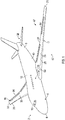
- Aircraft 2 includes a fuselage 4 extending from a nose portion 6 to a tail portion 8 through a body portion 10.
- Body portion 10 houses an aircraft cabin 14 that includes a crew compartment 15 and a passenger compartment 16.
- Body portion 10 supports a first wing 17 and a second wing 18.
- First wing 17 extends from a first root portion 20 to a first tip portion 21 through a first airfoil portion 23.
- First airfoil portion 23 includes a leading edge 25 and a trailing edge 26.
- Second wing 18 extends from a second root portion (not shown) to a second tip portion 31 through a second airfoil portion 33.
- Second airfoil portion 33 includes a leading edge 35 and a trailing edge 36.
- Tail portion 8 includes a stabilizer 38.
- the aircraft 2 includes a first flight control surface system and a second flight control surface system configured to adjust the lift and drag characteristics of the first wing 17 and the second wing 18.
- the flight control surface systems may include but are not limited to flap systems, aileron systems, elevator systems, rudder systems, spoiler systems, slat systems, and any other known flight control surface system known to one of skill in the art.
- the first flight control surface system is a flap system 47 and the second flight control surface system is a slat system 57.
- the flap system 47 includes one or more flaps 48 and the slat system 57 includes one or more slats 58.
- the flaps 48 may be located on the trailing edge 26 and the slats 58 may be located on the leading edge 25.
- FIG. 2 illustrates a schematic view of a conventional secondary flight control system 100.
- the aircraft typically contains separate power distribution units (PDUs) for each flight control surface system.
- FIG. 2 shows a secondary flight control system 100 of an aircraft having a first flight control surface system and a second flight control surface system.
- the secondary flight control system 100 may include one or more flight control surface systems.
- the flight control surface systems may include but are not limited to flap systems, aileron systems, elevator systems, rudder systems, spoiler systems, slat systems, and any other known flight control surface system known to one of skill in the art.
- flap systems flap systems
- aileron systems elevator systems
- rudder systems spoiler systems
- slat systems any other known flight control surface system known to one of skill in the art.
- the first flight control surface system is a flap system 47 and the second flight control surface system is a slat system 57.
- the flap system 47 includes one or more flaps 48 and the slat system 57 includes one or more slats 58.
- the slat system 57 is operably connected to a slat power distribution unit (PDU) 150a.
- the slat PDU 150a is dedicated to the slat system 57 and is configured to transmit torque to each slat 58 of the slat system 57.
- the slat PDU 150a is also in electronic communication with a slat electronic control unit (ECU) 170a and a slat monitor 180a. There may be a slat ECU 170a and a slat monitor 180a for the port side 2a of the aircraft and the starboard side 2b of the aircraft 2.
- the slat ECU 170a is configured to control the slat PDU 150a and the slat monitor 180a is configured to monitor the performance of the slat system 57.
- the slat monitor 180a may be in communication with a plurality of sensors (not shown) operably connected to each slat 58 to monitor the performance of the slat system 57.
- the flap system 58 is operably connected to a flap PDU 150b.
- the flap PDU 150b is dedicated to the flap system 47 and is configured to transmit torque to each flap 48 of the flap system 47.
- the flap PDU 150b is also in electronic communication with a flap electronic control unit (ECU) 170b and a flap monitor 180b.
- ECU flap electronic control unit
- the flap ECU 170a is configured to control the flap PDU 150b and the flap monitor 180b is configured to monitor the performance of the flap system 47.
- the flap monitor 180b may be in communication with a plurality of sensors (not shown) operably connected to each flap 48 to monitor the performance of the flap system 47.
- FIG. 3 illustrates a schematic view of a secondary flight control system 200, in accordance with an embodiment of the present disclosure.
- FIG. 3 shows a secondary flight control system 200 of an aircraft having a first flight control surface system and a second flight control surface system.
- the secondary flight control system 200 may include one or more flight control surface systems.
- the flight control surface systems may include but are not limited to flap systems, aileron systems, elevator systems, rudder systems, spoiler systems, slat systems, and any other known flight control surface system known to one of skill in the art.
- flap systems flap systems
- aileron systems elevator systems
- rudder systems spoiler systems
- slat systems any other known flight control surface system known to one of skill in the art.
- the first flight control surface system is a flap system 47 and the second flight control surface system is a slat system 57.
- the flap system 47 includes one or more flaps 48 and the slat system 57 includes one or more slats 58.
- the slat system 57 and the flap system 47 are each operably connected to a PDU 250.
- the PDU 250 is configured to transmit torque to one or more flight control surface systems. In the example illustrated in FIG. 3 , the PDU 250 is configured to transmit torque to the slat system 57 and the flap system 47. Torque may be output from the PDU 250 to a T-gearbox 210.
- the PDU 250 may be operably connected to the T-gearbox 210 through a torque tube 290.
- the T-gearbox 210 is configured to split the torque from the PDU 250 into two or more drive lines D1, D2. In the example illustrated in FIG. 3 , the T-gearbox 210 splits the torque from the PDU 250 into a first drive line D1 towards the slat system 57 and a second drive line towards the flap system 47.
- the T-gearbox 210 is operably connected to the slat system 57 through a first clutch 230a.
- a torque tube 290 may operably connect the first clutch 230a to the T-gearbox 210.
- a torque tube 290 may operably connect the slat system 57 to the first clutch 230a.
- the first clutch 230a may be configured to engage and disengage the slat system 57 from the T-gearbox 210.
- a first brake 220a may be operably connected to the slat system 57 along the first drive line D1 from the T-gearbox 210 to the slat system 57. In the illustrated example of FIG. 3 , the first brake 220a may be operably connected to a torque tube 290 operably connecting the first clutch 230a to the slat system 57.
- the first brake 220a may be configured to stop the transmission of torque along the first drive line D1.
- the T-gearbox 210 is operably connected to the flap system 47 through a second clutch 230b.
- a torque tube 290 may operably connect the second clutch 230b to the T-gearbox 210.
- a torque tube 290 may operably connect the flap system 47 to the second clutch 230b.
- the second clutch 230b may be configured to engage and disengage the flap system 47 from the T-gearbox 210.
- a second brake 220b may be operably connected to the flap system 47 along the second drive line D2 from the T-gearbox 210 to the flap system 47.
- the second brake 220b may be operably connected to a torque tube 290 operably connecting the second clutch 230b to the flap system 47.
- the second brake 220b may be configured to stop the transmission of torque along the second drive line D2.
- the PDU 250 is also in electronic communication with a control system 270.
- the control system 270 may include one or more slat/flap electronic control units (SFECU) for redundancy.
- the control system 270 may include a line-replacement unit (LRU) for redundancy.
- the control system 270 is configured to actuate the PDU 250.
- the control system 270 is also configured to monitor the performance of the slat system 57 and the flap system 47.
- the control system 270 may be in communication with a plurality of sensors (not shown) operably connected to each slat 58 to monitor the performance of the slat system 57.
- the control system 270 may be in communication with a plurality of sensors (not shown) operably connected to each flap 48 to monitor the performance of the flap system 47.
- a single PDU 250 is utilized, about 50% of the power electronics may be eliminated.
- the control system 270 may include a processor and an associated memory.
- the processor may be, but is not limited to, a single-processor or multiprocessor system of any of a wide array of possible architectures, including field programmable gate array (FPGA), central processing unit (CPU), application specific integrated circuits (ASIC), digital signal processor (DSP) or graphics processing unit (GPU) hardware arranged homogenously or heterogeneously.
- the memory may be but is not limited to a random access memory (RAM), read only memory (ROM), or other electronic, optical, magnetic or any other computer readable medium.
- weight reduction may be achieved by utilizing a common PDU and common control system in the secondary flight control system 200 illustrated in FIG. 3 , as opposed to the conventional secondary flight control system 100 shown in FIG. 2 that utilizes dedicated PDUs, monitors, and ECUs for each flight control surface system, which increases the weight.
- FIG. 4 shows a flow process illustrating a method 400 of assembling a secondary flight control system 200 according to an embodiment of the present disclosure.
- a first flight control surface system is installed onto a wing 18, 17 of an aircraft 2.
- the first flight control surface system is a slat system 57 including one or more slats 58.
- a second flight control surface system is installed onto the wing 18, 17 of an aircraft 2.
- the first flight control surface system is a flap system 47 including one or more flaps 48.
- a PDU 250 is operably connected to the first flight control surface system and the second flight control surface system. The PDU 250 is configured to generate torque to actuate the first flight control surface system and the second flight control surface system.
- the PDU 250 may be operably connected to the first flight control surface system and the second flight control surface system by: operably connecting a T-gearbox 210 to the PDU 250; operably connecting the T-gearbox 210 to the first flight control surface system; and operably connecting the T-gearbox 210 to the second flight control surface system.
- the T-gearbox 210 is configured to split the torque from the PDU 250 into a first drive line D1 towards the first flight control surface system and a second drive line D2 towards the second flight control surface system.
- the T-gearbox 210 may be operably connected to the first flight control surface system by: operably connecting a first clutch 230a to the first flight control surface system; and operably connecting the first clutch 230a to the T-gearbox 210.
- the first clutch 230a is configured to engage and disengage the first flight control surface system from the T-gearbox 210.
- the T-gearbox 210 may be operably connected to the second flight control surface system by: operably connecting a second clutch 230b to the second flight control surface system; and operably connecting the second clutch 230b to the T-gearbox 210.
- the second clutch 230b is configured to engage and disengage the second flight control surface system from the T-gearbox 210.
- the method 400 may also comprise: operably connecting a first brake 220a to the first flight control surface system along the first drive line D1.
- the first brake 220a is configured to stop transmission of torque along the first drive line D1.
- the method 400 may further comprise: operably connecting a second brake 220b to the second flight control surface system along the second drive line D2.
- the second brake 220b is configured to stop transmission of torque along the second drive line D2.
- the method 400 may also comprise: electronically connecting a control system 270 to the PDU 250.
- the control system 270 is configured to actuate the PDU 250 and monitor the first flight control surface system and the second flight control surface system.
- FIG. 5 shows a flow process illustrating a method 500 actuating one or more flight control surface systems for an aircraft 2, according to an embodiment of the present disclosure.
- torque is generated using a PDU 250.
- the torque generated from the PDU 250 is split into a first drive line D1 towards a first flight control surface system and a second drive line D2 towards a second flight control surface system.
- the first flight control surface system is a slat system 57 including one or more slats 58.
- the second flight control surface system is a flap system 47 including one or more flaps 48.
- the toque may be split using a T-gearbox 210, as described above.
- at least one of the first flight control surface system and the second flight control surface system is actuated using the torque generated form the PDU 250.
Landscapes
- Engineering & Computer Science (AREA)
- Mechanical Engineering (AREA)
- Aviation & Aerospace Engineering (AREA)
- Automation & Control Theory (AREA)
- Retarders (AREA)
- Transmission Devices (AREA)
- Toys (AREA)
Abstract
Description
- The subject matter disclosed herein generally relates to flight control surface actuation systems, and more specifically to an apparatus and a method for transferring torque in a flight control surface actuation system.
- Flight control surface actuation is commonly accomplished by separate drive systems and control systems, which leads to added weight and complexity.
- According to one embodiment, a secondary flight control system is provided. The secondary flight control system comprising: a first flight control surface system; a second flight control surface system; and a power distribution unit operably connected to the first flight control surface system and the second flight control surface system, wherein the power distribution unit is configured to generate torque to actuate the first flight control surface system and the second flight control surface system.
- In addition to one or more of the features described above, or as an alternative, further embodiments may include a T-gearbox operably connected to the power distribution unit, the first flight control surface system, and the second flight control surface system, wherein the T-gearbox is configured to split the torque from the power distribution unit into a first drive line towards the first flight control surface system and a second drive line towards the second flight control surface system.
- In addition to one or more of the features described above, or as an alternative, further embodiments may include a first clutch operably connecting the first flight control surface system and the T-gearbox, wherein the first clutch is configured to engage and disengage the first flight control surface system from the T-gearbox.
- In addition to one or more of the features described above, or as an alternative, further embodiments may include a second clutch operably connecting the second flight control surface system and the T-gearbox, wherein the second clutch is configured to engage and disengage the second flight control surface system from the T-gearbox.
- In addition to one or more of the features described above, or as an alternative, further embodiments may include a first brake operably connected to the first flight control surface system along the first drive line, wherein the first brake is configured to stop transmission of torque along the first drive line.
- In addition to one or more of the features described above, or as an alternative, further embodiments may include a second brake operably connected to the second flight control surface system along the second drive line, wherein the second brake is configured to stop transmission of torque along the second drive line.
- In addition to one or more of the features described above, or as an alternative, further embodiments may include a control system in electronic communication with the power distribution unit, wherein the control system is configured to actuate the power distribution unit and monitor the first flight control surface system and the second flight control surface system.
- In addition to one or more of the features described above, or as an alternative, further embodiments may include that the first flight control surface system is a slat system including one or more slats.
- In addition to one or more of the features described above, or as an alternative, further embodiments may include that the second flight control surface system is a flap system including one or more flaps.
- In addition to one or more of the features described above, or as an alternative, further embodiments may include that the second flight control surface system is a flap system including one or more flaps.
- According to another embodiment, a method of assembling a secondary flight control system is provided. The method comprising: installing a first flight control surface system onto a wing of an aircraft; installing a second flight control surface system onto the wing of an aircraft; and operably connecting a power distribution unit to the first flight control surface system and the second flight control surface system, wherein the power distribution unit is configured to generate torque to actuate the first flight control surface system and the second flight control surface system.
- In addition to one or more of the features described above, or as an alternative, further embodiments may include that the operably connecting a power distribution unit to the first flight control surface system and the second flight control surface system further comprises: operably connecting a T-gearbox to the power distribution unit; operably connecting the T-gearbox to the first flight control surface system; and operably connecting the T-gearbox to the second flight control surface system, wherein the T-gearbox is configured to split the torque from the power distribution unit into a first drive line towards the first flight control surface system and a second drive line towards the second flight control surface system.
- In addition to one or more of the features described above, or as an alternative, further embodiments may include that the operably connecting the T-gearbox to the first flight control surface system further comprises: operably connecting a first clutch to the first flight control surface system; and operably connecting the first clutch to the T-gearbox, wherein the first clutch is configured to engage and disengage the first flight control surface system from the T-gearbox.
- In addition to one or more of the features described above, or as an alternative, further embodiments may include that the operably connecting the T-gearbox to the second flight control surface system further comprises: operably connecting a second clutch to the second flight control surface system; and operably connecting the second clutch to the T-gearbox, wherein the second clutch is configured to engage and disengage the second flight control surface system from the T-gearbox.
- In addition to one or more of the features described above, or as an alternative, further embodiments may include operably connecting a first brake to the first flight control surface system along the first drive line, wherein the first brake is configured to stop transmission of torque along the first drive line.
- In addition to one or more of the features described above, or as an alternative, further embodiments may include operably connecting a second brake to the second flight control surface system along the second drive line, wherein the second brake is configured to stop transmission of torque along the second drive line.
- In addition to one or more of the features described above, or as an alternative, further embodiments may include electronically connecting a control system to the power distribution unit, wherein the control system is configured to actuate the power distribution unit and monitor the first flight control surface system and the second flight control surface system.
- In addition to one or more of the features described above, or as an alternative, further embodiments may include that the first flight control surface system is a slat system including one or more slats.
- In addition to one or more of the features described above, or as an alternative, further embodiments may include that the second flight control surface system is a flap system including one or more flaps.
- According to another embodiment, a method of actuating one or more flight control surface systems for an aircraft is provided. The method comprising: generating torque using a power distribution unit; splitting the torque generated from the power distribution unit into a first drive line towards a first flight control surface system and a second drive line towards a second flight control surface system; and actuating at least one of the first flight control surface system and the second flight control surface system using the torque generated form the power distribution unit.
- Technical effects of embodiments of the present disclosure include utilizing a common power distribution unit to actuate a slat system and a flap system.
- The foregoing features and elements may be combined in various combinations without exclusivity, unless expressly indicated otherwise. These features and elements as well as the operation thereof will become more apparent in light of the following description and the accompanying drawings. It should be understood, however, that the following description and drawings are intended to be illustrative and explanatory in nature and non-limiting.
- The following descriptions should not be considered limiting in any way. With reference to the accompanying drawings, like elements are numbered alike:
-
FIG. 1 is a perspective view of an aircraft, according to an embodiment of the present disclosure; -
FIG. 2 is conventional secondary flight control system; -
FIG. 3 is a secondary flight control system utilizing a single power drive unit to actuate two flight control surface systems, according to an embodiment of the present disclosure; -
FIG. 4 is a flow process illustrating a method of assembling a secondary flight control system, according to an embodiment of the present disclosure; and -
FIG. 5 is a flow process illustrating a method of actuating one or more flight control surface systems for an aircraft, according to an embodiment of the present disclosure. - A detailed description of one or more embodiments of the disclosed apparatus and method are presented herein by way of exemplification and not limitation with reference to the Figures.
- Referring now to
FIG. 1 , which shows a perspective view of an aircraft 2 that may incorporate embodiments of the present disclosure. Aircraft 2 includes a fuselage 4 extending from a nose portion 6 to a tail portion 8 through abody portion 10.Body portion 10 houses an aircraft cabin 14 that includes acrew compartment 15 and apassenger compartment 16.Body portion 10 supports afirst wing 17 and asecond wing 18.First wing 17 extends from a first root portion 20 to afirst tip portion 21 through afirst airfoil portion 23.First airfoil portion 23 includes a leadingedge 25 and atrailing edge 26.Second wing 18 extends from a second root portion (not shown) to asecond tip portion 31 through asecond airfoil portion 33.Second airfoil portion 33 includes a leadingedge 35 and atrailing edge 36. Tail portion 8 includes astabilizer 38. The aircraft 2 includes a first flight control surface system and a second flight control surface system configured to adjust the lift and drag characteristics of thefirst wing 17 and thesecond wing 18. The flight control surface systems may include but are not limited to flap systems, aileron systems, elevator systems, rudder systems, spoiler systems, slat systems, and any other known flight control surface system known to one of skill in the art. In the illustrated example ofFIG. 1 , the first flight control surface system is aflap system 47 and the second flight control surface system is aslat system 57. Theflap system 47 includes one ormore flaps 48 and theslat system 57 includes one ormore slats 58. Theflaps 48 may be located on thetrailing edge 26 and theslats 58 may be located on the leadingedge 25. - Referring now to
FIG. 2 with continued reference toFIG. 1 .FIG. 2 illustrates a schematic view of a conventional secondaryflight control system 100. In aircraft having more than two flight control surface systems, the aircraft typically contains separate power distribution units (PDUs) for each flight control surface system.FIG. 2 shows a secondaryflight control system 100 of an aircraft having a first flight control surface system and a second flight control surface system. It is understood that the secondaryflight control system 100 may include one or more flight control surface systems. As mentioned above, the flight control surface systems may include but are not limited to flap systems, aileron systems, elevator systems, rudder systems, spoiler systems, slat systems, and any other known flight control surface system known to one of skill in the art. In the illustrated example ofFIG. 2 , the first flight control surface system is aflap system 47 and the second flight control surface system is aslat system 57. Theflap system 47 includes one ormore flaps 48 and theslat system 57 includes one ormore slats 58. - The
slat system 57 is operably connected to a slat power distribution unit (PDU) 150a. Theslat PDU 150a is dedicated to theslat system 57 and is configured to transmit torque to eachslat 58 of theslat system 57. Theslat PDU 150a is also in electronic communication with a slat electronic control unit (ECU) 170a and aslat monitor 180a. There may be aslat ECU 170a and aslat monitor 180a for theport side 2a of the aircraft and thestarboard side 2b of the aircraft 2. Theslat ECU 170a is configured to control theslat PDU 150a and theslat monitor 180a is configured to monitor the performance of theslat system 57. Theslat monitor 180a may be in communication with a plurality of sensors (not shown) operably connected to eachslat 58 to monitor the performance of theslat system 57. - The
flap system 58 is operably connected to aflap PDU 150b. Theflap PDU 150b is dedicated to theflap system 47 and is configured to transmit torque to eachflap 48 of theflap system 47. Theflap PDU 150b is also in electronic communication with a flap electronic control unit (ECU) 170b and aflap monitor 180b. There may be aflap ECU 170b and aflap monitor 180b for theport side 2a of the aircraft and thestarboard side 2b of the aircraft. Theflap ECU 170a is configured to control theflap PDU 150b and theflap monitor 180b is configured to monitor the performance of theflap system 47. Theflap monitor 180b may be in communication with a plurality of sensors (not shown) operably connected to eachflap 48 to monitor the performance of theflap system 47. - Referring now to
FIG. 3 with continued reference toFIG. 1 .FIG. 3 illustrates a schematic view of a secondaryflight control system 200, in accordance with an embodiment of the present disclosure.FIG. 3 shows a secondaryflight control system 200 of an aircraft having a first flight control surface system and a second flight control surface system. It is understood that the secondaryflight control system 200 may include one or more flight control surface systems. As mentioned above, the flight control surface systems may include but are not limited to flap systems, aileron systems, elevator systems, rudder systems, spoiler systems, slat systems, and any other known flight control surface system known to one of skill in the art. In the illustrated example ofFIG. 3 , the first flight control surface system is aflap system 47 and the second flight control surface system is aslat system 57. Theflap system 47 includes one ormore flaps 48 and theslat system 57 includes one ormore slats 58. - The
slat system 57 and theflap system 47 are each operably connected to aPDU 250. ThePDU 250 is configured to transmit torque to one or more flight control surface systems. In the example illustrated inFIG. 3 , thePDU 250 is configured to transmit torque to theslat system 57 and theflap system 47. Torque may be output from thePDU 250 to a T-gearbox 210. ThePDU 250 may be operably connected to the T-gearbox 210 through atorque tube 290. The T-gearbox 210 is configured to split the torque from thePDU 250 into two or more drive lines D1, D2. In the example illustrated inFIG. 3 , the T-gearbox 210 splits the torque from thePDU 250 into a first drive line D1 towards theslat system 57 and a second drive line towards theflap system 47. - The T-
gearbox 210 is operably connected to theslat system 57 through a first clutch 230a. Atorque tube 290 may operably connect the first clutch 230a to the T-gearbox 210. Atorque tube 290 may operably connect theslat system 57 to the first clutch 230a. The first clutch 230a may be configured to engage and disengage theslat system 57 from the T-gearbox 210. Afirst brake 220a may be operably connected to theslat system 57 along the first drive line D1 from the T-gearbox 210 to theslat system 57. In the illustrated example ofFIG. 3 , thefirst brake 220a may be operably connected to atorque tube 290 operably connecting the first clutch 230a to theslat system 57. Thefirst brake 220a may be configured to stop the transmission of torque along the first drive line D1. - The T-
gearbox 210 is operably connected to theflap system 47 through a second clutch 230b. Atorque tube 290 may operably connect the second clutch 230b to the T-gearbox 210. Atorque tube 290 may operably connect theflap system 47 to the second clutch 230b. The second clutch 230b may be configured to engage and disengage theflap system 47 from the T-gearbox 210. Asecond brake 220b may be operably connected to theflap system 47 along the second drive line D2 from the T-gearbox 210 to theflap system 47. In the illustrated example ofFIG. 3 , thesecond brake 220b may be operably connected to atorque tube 290 operably connecting the second clutch 230b to theflap system 47. Thesecond brake 220b may be configured to stop the transmission of torque along the second drive line D2. - The
PDU 250 is also in electronic communication with acontrol system 270. Thecontrol system 270 may include one or more slat/flap electronic control units (SFECU) for redundancy. Thecontrol system 270 may include a line-replacement unit (LRU) for redundancy. Thecontrol system 270 is configured to actuate thePDU 250. Thecontrol system 270 is also configured to monitor the performance of theslat system 57 and theflap system 47. Thecontrol system 270 may be in communication with a plurality of sensors (not shown) operably connected to eachslat 58 to monitor the performance of theslat system 57. Thecontrol system 270 may be in communication with a plurality of sensors (not shown) operably connected to eachflap 48 to monitor the performance of theflap system 47. Advantageously, since asingle PDU 250 is utilized, about 50% of the power electronics may be eliminated. - The
control system 270 may include a processor and an associated memory. The processor may be, but is not limited to, a single-processor or multiprocessor system of any of a wide array of possible architectures, including field programmable gate array (FPGA), central processing unit (CPU), application specific integrated circuits (ASIC), digital signal processor (DSP) or graphics processing unit (GPU) hardware arranged homogenously or heterogeneously. The memory may be but is not limited to a random access memory (RAM), read only memory (ROM), or other electronic, optical, magnetic or any other computer readable medium. - Advantageously, weight reduction may be achieved by utilizing a common PDU and common control system in the secondary
flight control system 200 illustrated inFIG. 3 , as opposed to the conventional secondaryflight control system 100 shown inFIG. 2 that utilizes dedicated PDUs, monitors, and ECUs for each flight control surface system, which increases the weight. - Referring now to
FIG. 4 , with continued referenceFIGs. 1-3 .FIG. 4 shows a flow process illustrating amethod 400 of assembling a secondaryflight control system 200 according to an embodiment of the present disclosure. Atblock 404, a first flight control surface system is installed onto awing slat system 57 including one ormore slats 58. Atblock 406, a second flight control surface system is installed onto thewing flap system 47 including one or more flaps 48. Atblock 408, aPDU 250 is operably connected to the first flight control surface system and the second flight control surface system. ThePDU 250 is configured to generate torque to actuate the first flight control surface system and the second flight control surface system. - The
PDU 250 may be operably connected to the first flight control surface system and the second flight control surface system by: operably connecting a T-gearbox 210 to thePDU 250; operably connecting the T-gearbox 210 to the first flight control surface system; and operably connecting the T-gearbox 210 to the second flight control surface system. The T-gearbox 210 is configured to split the torque from thePDU 250 into a first drive line D1 towards the first flight control surface system and a second drive line D2 towards the second flight control surface system. The T-gearbox 210 may be operably connected to the first flight control surface system by: operably connecting a first clutch 230a to the first flight control surface system; and operably connecting the first clutch 230a to the T-gearbox 210. The first clutch 230a is configured to engage and disengage the first flight control surface system from the T-gearbox 210. - The T-
gearbox 210 may be operably connected to the second flight control surface system by: operably connecting a second clutch 230b to the second flight control surface system; and operably connecting the second clutch 230b to the T-gearbox 210. The second clutch 230b is configured to engage and disengage the second flight control surface system from the T-gearbox 210. - The
method 400 may also comprise: operably connecting afirst brake 220a to the first flight control surface system along the first drive line D1. Thefirst brake 220a is configured to stop transmission of torque along the first drive line D1. Themethod 400 may further comprise: operably connecting asecond brake 220b to the second flight control surface system along the second drive line D2. Thesecond brake 220b is configured to stop transmission of torque along the second drive line D2. Themethod 400 may also comprise: electronically connecting acontrol system 270 to thePDU 250. Thecontrol system 270 is configured to actuate thePDU 250 and monitor the first flight control surface system and the second flight control surface system. - While the above description has described the flow process of
FIG. 4 in a particular order, it should be appreciated that unless otherwise specifically required in the attached claims the ordering of the steps may be varied. - Referring now to
FIG. 5 , with continued referenceFIGs. 1-3 .FIG. 5 shows a flow process illustrating amethod 500 actuating one or more flight control surface systems for an aircraft 2, according to an embodiment of the present disclosure. Atblock 504, torque is generated using aPDU 250. Atblock 506, the torque generated from thePDU 250 is split into a first drive line D1 towards a first flight control surface system and a second drive line D2 towards a second flight control surface system. In an embodiment, the first flight control surface system is aslat system 57 including one ormore slats 58. In an embodiment, the second flight control surface system is aflap system 47 including one or more flaps 48. The toque may be split using a T-gearbox 210, as described above. Atblock 508, at least one of the first flight control surface system and the second flight control surface system is actuated using the torque generated form thePDU 250. - While the above description has described the flow process of
FIG. 5 in a particular order, it should be appreciated that unless otherwise specifically required in the attached claims that the ordering of the steps may be varied. - The term "about" is intended to include the degree of error associated with measurement of the particular quantity based upon the equipment available at the time of filing the application. For example, "about" can include a range of ± 8% or 5%, or 2% of a given value.
- The terminology used herein is for the purpose of describing particular embodiments only and is not intended to be limiting of the present disclosure. As used herein, the singular forms "a", "an" and "the" are intended to include the plural forms as well, unless the context clearly indicates otherwise. It will be further understood that the terms "comprises" and/or "comprising," when used in this specification, specify the presence of stated features, integers, steps, operations, elements, and/or components, but do not preclude the presence or addition of one or more other features, integers, steps, operations, element components, and/or groups thereof.
- While the present disclosure has been described with reference to an exemplary embodiment or embodiments, it will be understood by those skilled in the art that various changes may be made and equivalents may be substituted for elements thereof without departing from the scope of the invention as defined by the claims. In addition, many modifications may be made to adapt a particular situation or material to the teachings of the present disclosure without departing from the scope of the invention. Therefore, it is intended that the present disclosure not be limited to the particular embodiment disclosed as the best mode contemplated for carrying out this present disclosure, but that the present disclosure will include all embodiments falling within the scope of the claims.
Claims (10)
- A secondary flight control system, comprising:a first flight control surface system (47);a second flight control surface system (57); anda power distribution unit (150a) operably connected to the first flight control surface system and the second flight control surface system, wherein the power distribution unit is configured to generate torque to actuate the first flight control surface system and the second flight control surface system.
- The secondary flight control system of claim 1, further comprising:
a T-gearbox (210) operably connected to the power distribution unit, the first flight control surface system, and the second flight control surface system, wherein the T-gearbox is configured to split the torque from the power distribution unit into a first drive line towards the first flight control surface system and a second drive line towards the second flight control surface system. - The secondary flight control system of claim 2, further comprising:
a first clutch (230a) operably connecting the first flight control surface system and the T-gearbox, wherein the first clutch is configured to engage and disengage the first flight control surface system from the T-gearbox. - The secondary flight control system of claim 2, further comprising:
a second clutch (230b) operably connecting the second flight control surface system and the T-gearbox, wherein the second clutch is configured to engage and disengage the second flight control surface system from the T-gearbox. - The secondary flight control system of any of claims 2 to 4, further comprising:
a first brake (220a) operably connected to the first flight control surface system along the first drive line, wherein the first brake is configured to stop transmission of torque along the first drive line. - The secondary flight control system of any of claims 2 to 5, further comprising:
a second brake (220b) operably connected to the second flight control surface system along the second drive line, wherein the second brake is configured to stop transmission of torque along the second drive line. - The secondary flight control system of any preceding claim, further comprising:
a control system (270) in electronic communication with the power distribution unit, wherein the control system is configured to actuate the power distribution unit and monitor the first flight control surface system and the second flight control surface system. - The secondary flight control system of any preceding claim, wherein:
the first flight control surface system is a slat system (47) including one or more slats. - The secondary flight control system of any preceding claim, wherein:
the second flight control surface system is a flap system including one or more flaps. - A method of actuating one or more flight control surface systems for an aircraft, the method comprising:generating torque using a power distribution unit;splitting the torque generated from the power distribution unit into a first drive line towards a first flight control surface system and a second drive line towards a second flight control surface system; andactuating at least one of the first flight control surface system and the second flight control surface system using the torque generated form the power distribution unit.
Applications Claiming Priority (1)
| Application Number | Priority Date | Filing Date | Title |
|---|---|---|---|
| US15/821,058 US11111005B2 (en) | 2017-11-22 | 2017-11-22 | Control of multiple flight control surface systems using single power drive unit |
Publications (2)
| Publication Number | Publication Date |
|---|---|
| EP3489135A1 true EP3489135A1 (en) | 2019-05-29 |
| EP3489135B1 EP3489135B1 (en) | 2022-12-28 |
Family
ID=64426651
Family Applications (1)
| Application Number | Title | Priority Date | Filing Date |
|---|---|---|---|
| EP18207069.8A Active EP3489135B1 (en) | 2017-11-22 | 2018-11-19 | Control of multiple flight control surface systems using single power drive unit |
Country Status (4)
| Country | Link |
|---|---|
| US (1) | US11111005B2 (en) |
| EP (1) | EP3489135B1 (en) |
| BR (1) | BR102018073846B1 (en) |
| CA (1) | CA3024426A1 (en) |
Cited By (1)
| Publication number | Priority date | Publication date | Assignee | Title |
|---|---|---|---|---|
| EP3795467A1 (en) * | 2019-09-20 | 2021-03-24 | Goodrich Actuation Systems Limited | Actuation system |
Families Citing this family (3)
| Publication number | Priority date | Publication date | Assignee | Title |
|---|---|---|---|---|
| EP4112452B1 (en) * | 2021-06-29 | 2024-12-04 | Airbus Operations GmbH | Method and apparatus for conducting health monitoring |
| US12612154B2 (en) | 2024-03-14 | 2026-04-28 | Goodrich Actuation Systems Limited | Mechanical architecture for distributed flap actuation system |
| EP4725831A1 (en) * | 2024-10-14 | 2026-04-15 | Goodrich Actuation Systems Limited | Foldable wing tip actuation system |
Citations (4)
| Publication number | Priority date | Publication date | Assignee | Title |
|---|---|---|---|---|
| WO2008112363A2 (en) * | 2007-02-07 | 2008-09-18 | Parker Hannifin Corporation | Electromechanical actuating assembly |
| EP2039605A2 (en) * | 2007-09-19 | 2009-03-25 | Liebherr-Aerospace Lindenberg GmbH | Aircraft high-lift device system with overload protection |
| EP2251258A2 (en) * | 2009-05-12 | 2010-11-17 | Liebherr-Aerospace Lindenberg GmbH | Aircraft high-lift system and method for determining the operational state of same |
| DE102017111553A1 (en) * | 2016-07-07 | 2018-01-11 | Liebherr-Aerospace Lindenberg Gmbh | High Lift System |
Family Cites Families (12)
| Publication number | Priority date | Publication date | Assignee | Title |
|---|---|---|---|---|
| US4779822A (en) * | 1986-05-23 | 1988-10-25 | Sundstrand Corporation | Actuator system |
| US6824099B1 (en) * | 2003-07-10 | 2004-11-30 | The Boeing Company | Brake systems for aircraft wing flaps and other control surfaces |
| DE10353672A1 (en) | 2003-11-12 | 2005-06-23 | Airbus Deutschland Gmbh | Method for load limitation in drive systems |
| US8080966B2 (en) | 2008-07-03 | 2011-12-20 | Honeywell International Inc. | Motor control architecture for simultaneously controlling multiple motors |
| DE102010047512A1 (en) * | 2010-10-05 | 2012-04-05 | Airbus Operations Gmbh | High-lift system for an aircraft with two separate drive units |
| EP2695810B1 (en) * | 2012-08-09 | 2016-10-19 | Airbus Operations GmbH | Drive system for control surfaces of an aircraft |
| EP2947004B1 (en) * | 2014-05-23 | 2017-02-01 | Airbus Operations GmbH | Method for determining the position of a component in a high lift system of an aircraft, high lift system of an aircraft and aircraft |
| US10780977B2 (en) * | 2016-02-17 | 2020-09-22 | Hamilton Sunstrand Corporation | Aerodynamic control surface movement monitoring system |
| CN106741863B (en) * | 2016-11-17 | 2019-04-02 | 中国商用飞机有限责任公司 | High lift system for an aircraft |
| US10703462B2 (en) * | 2017-08-25 | 2020-07-07 | Hamilton Sunstrand Corporation | Flight control system regenerative braking |
| EP3495258A1 (en) * | 2017-12-06 | 2019-06-12 | Airbus Operations GmbH | Wing for an aircraft |
| GB201806477D0 (en) * | 2018-04-20 | 2018-06-06 | Moog Wolverhampton Ltd | System for an aircraft wing |
-
2017
- 2017-11-22 US US15/821,058 patent/US11111005B2/en active Active
-
2018
- 2018-11-15 CA CA3024426A patent/CA3024426A1/en active Pending
- 2018-11-19 EP EP18207069.8A patent/EP3489135B1/en active Active
- 2018-11-21 BR BR102018073846-1A patent/BR102018073846B1/en active IP Right Grant
Patent Citations (4)
| Publication number | Priority date | Publication date | Assignee | Title |
|---|---|---|---|---|
| WO2008112363A2 (en) * | 2007-02-07 | 2008-09-18 | Parker Hannifin Corporation | Electromechanical actuating assembly |
| EP2039605A2 (en) * | 2007-09-19 | 2009-03-25 | Liebherr-Aerospace Lindenberg GmbH | Aircraft high-lift device system with overload protection |
| EP2251258A2 (en) * | 2009-05-12 | 2010-11-17 | Liebherr-Aerospace Lindenberg GmbH | Aircraft high-lift system and method for determining the operational state of same |
| DE102017111553A1 (en) * | 2016-07-07 | 2018-01-11 | Liebherr-Aerospace Lindenberg Gmbh | High Lift System |
Cited By (2)
| Publication number | Priority date | Publication date | Assignee | Title |
|---|---|---|---|---|
| EP3795467A1 (en) * | 2019-09-20 | 2021-03-24 | Goodrich Actuation Systems Limited | Actuation system |
| US12037103B2 (en) | 2019-09-20 | 2024-07-16 | Goodrich Actuation Systems Limited | Actuation system |
Also Published As
| Publication number | Publication date |
|---|---|
| CA3024426A1 (en) | 2019-05-22 |
| EP3489135B1 (en) | 2022-12-28 |
| US11111005B2 (en) | 2021-09-07 |
| US20190152583A1 (en) | 2019-05-23 |
| BR102018073846B1 (en) | 2022-05-10 |
| BR102018073846A2 (en) | 2019-06-18 |
Similar Documents
| Publication | Publication Date | Title |
|---|---|---|
| CN102414081B (en) | Aircraft control system with integrated modular architecture | |
| EP3489135B1 (en) | Control of multiple flight control surface systems using single power drive unit | |
| CN102458995B (en) | aircraft with high lift system | |
| EP1301835B1 (en) | Flight control module with integrated spoiler actuator control electronics | |
| CN102458983B (en) | High lift system for aircraft, aircraft system and propeller aircraft with high lift system | |
| EP1301393B1 (en) | Flight control modules merged into the integrated modular avionics | |
| CN104955729B (en) | Aircraft landing gear longitudinal force control | |
| CN100522743C (en) | Method for load limitation in drive systems for a high lift system for aeroplanes | |
| EP3254960A1 (en) | Electrical architecture for slat/flap control using smart sensors and effectors | |
| EP3363697B1 (en) | Antiskid operation during degraded operation | |
| CN102046467A (en) | Error tolerant adjustment system for adjusting servo tabs of an aircraft, comprising a control mechanism with a fixed rotational axis | |
| EP3434586B1 (en) | Brake load alleviation functions | |
| EP3309023B1 (en) | Systems and methods for emergency aircraft brake operation | |
| CN103635386A (en) | Electronically synchronized flap system | |
| US20150314852A1 (en) | Electronic flap actuation system | |
| EP2949527A2 (en) | Autobraking system with course trajectory adjustment | |
| US8191832B2 (en) | Method and device for an aircraft buffet reduction | |
| PL442960A1 (en) | Safety system for aircraft with mechanical control system |
Legal Events
| Date | Code | Title | Description |
|---|---|---|---|
| PUAI | Public reference made under article 153(3) epc to a published international application that has entered the european phase |
Free format text: ORIGINAL CODE: 0009012 |
|
| STAA | Information on the status of an ep patent application or granted ep patent |
Free format text: STATUS: THE APPLICATION HAS BEEN PUBLISHED |
|
| AK | Designated contracting states |
Kind code of ref document: A1 Designated state(s): AL AT BE BG CH CY CZ DE DK EE ES FI FR GB GR HR HU IE IS IT LI LT LU LV MC MK MT NL NO PL PT RO RS SE SI SK SM TR |
|
| AX | Request for extension of the european patent |
Extension state: BA ME |
|
| STAA | Information on the status of an ep patent application or granted ep patent |
Free format text: STATUS: REQUEST FOR EXAMINATION WAS MADE |
|
| 17P | Request for examination filed |
Effective date: 20191129 |
|
| RBV | Designated contracting states (corrected) |
Designated state(s): AL AT BE BG CH CY CZ DE DK EE ES FI FR GB GR HR HU IE IS IT LI LT LU LV MC MK MT NL NO PL PT RO RS SE SI SK SM TR |
|
| STAA | Information on the status of an ep patent application or granted ep patent |
Free format text: STATUS: EXAMINATION IS IN PROGRESS |
|
| 17Q | First examination report despatched |
Effective date: 20210224 |
|
| GRAP | Despatch of communication of intention to grant a patent |
Free format text: ORIGINAL CODE: EPIDOSNIGR1 |
|
| STAA | Information on the status of an ep patent application or granted ep patent |
Free format text: STATUS: GRANT OF PATENT IS INTENDED |
|
| INTG | Intention to grant announced |
Effective date: 20220721 |
|
| RIN1 | Information on inventor provided before grant (corrected) |
Inventor name: MAYER, TIMOTHY MICHAEL Inventor name: HARRINGTON, ERIK |
|
| GRAS | Grant fee paid |
Free format text: ORIGINAL CODE: EPIDOSNIGR3 |
|
| GRAA | (expected) grant |
Free format text: ORIGINAL CODE: 0009210 |
|
| STAA | Information on the status of an ep patent application or granted ep patent |
Free format text: STATUS: THE PATENT HAS BEEN GRANTED |
|
| AK | Designated contracting states |
Kind code of ref document: B1 Designated state(s): AL AT BE BG CH CY CZ DE DK EE ES FI FR GB GR HR HU IE IS IT LI LT LU LV MC MK MT NL NO PL PT RO RS SE SI SK SM TR |
|
| REG | Reference to a national code |
Ref country code: GB Ref legal event code: FG4D |
|
| REG | Reference to a national code |
Ref country code: CH Ref legal event code: EP |
|
| REG | Reference to a national code |
Ref country code: DE Ref legal event code: R096 Ref document number: 602018044673 Country of ref document: DE |
|
| REG | Reference to a national code |
Ref country code: AT Ref legal event code: REF Ref document number: 1540337 Country of ref document: AT Kind code of ref document: T Effective date: 20230115 |
|
| REG | Reference to a national code |
Ref country code: IE Ref legal event code: FG4D |
|
| REG | Reference to a national code |
Ref country code: LT Ref legal event code: MG9D |
|
| PG25 | Lapsed in a contracting state [announced via postgrant information from national office to epo] |
Ref country code: SE Free format text: LAPSE BECAUSE OF FAILURE TO SUBMIT A TRANSLATION OF THE DESCRIPTION OR TO PAY THE FEE WITHIN THE PRESCRIBED TIME-LIMIT Effective date: 20221228 Ref country code: NO Free format text: LAPSE BECAUSE OF FAILURE TO SUBMIT A TRANSLATION OF THE DESCRIPTION OR TO PAY THE FEE WITHIN THE PRESCRIBED TIME-LIMIT Effective date: 20230328 Ref country code: LT Free format text: LAPSE BECAUSE OF FAILURE TO SUBMIT A TRANSLATION OF THE DESCRIPTION OR TO PAY THE FEE WITHIN THE PRESCRIBED TIME-LIMIT Effective date: 20221228 Ref country code: FI Free format text: LAPSE BECAUSE OF FAILURE TO SUBMIT A TRANSLATION OF THE DESCRIPTION OR TO PAY THE FEE WITHIN THE PRESCRIBED TIME-LIMIT Effective date: 20221228 |
|
| REG | Reference to a national code |
Ref country code: NL Ref legal event code: MP Effective date: 20221228 |
|
| REG | Reference to a national code |
Ref country code: AT Ref legal event code: MK05 Ref document number: 1540337 Country of ref document: AT Kind code of ref document: T Effective date: 20221228 |
|
| PG25 | Lapsed in a contracting state [announced via postgrant information from national office to epo] |
Ref country code: RS Free format text: LAPSE BECAUSE OF FAILURE TO SUBMIT A TRANSLATION OF THE DESCRIPTION OR TO PAY THE FEE WITHIN THE PRESCRIBED TIME-LIMIT Effective date: 20221228 Ref country code: LV Free format text: LAPSE BECAUSE OF FAILURE TO SUBMIT A TRANSLATION OF THE DESCRIPTION OR TO PAY THE FEE WITHIN THE PRESCRIBED TIME-LIMIT Effective date: 20221228 Ref country code: HR Free format text: LAPSE BECAUSE OF FAILURE TO SUBMIT A TRANSLATION OF THE DESCRIPTION OR TO PAY THE FEE WITHIN THE PRESCRIBED TIME-LIMIT Effective date: 20221228 Ref country code: GR Free format text: LAPSE BECAUSE OF FAILURE TO SUBMIT A TRANSLATION OF THE DESCRIPTION OR TO PAY THE FEE WITHIN THE PRESCRIBED TIME-LIMIT Effective date: 20230329 |
|
| P01 | Opt-out of the competence of the unified patent court (upc) registered |
Effective date: 20230522 |
|
| PG25 | Lapsed in a contracting state [announced via postgrant information from national office to epo] |
Ref country code: NL Free format text: LAPSE BECAUSE OF FAILURE TO SUBMIT A TRANSLATION OF THE DESCRIPTION OR TO PAY THE FEE WITHIN THE PRESCRIBED TIME-LIMIT Effective date: 20221228 |
|
| PG25 | Lapsed in a contracting state [announced via postgrant information from national office to epo] |
Ref country code: SM Free format text: LAPSE BECAUSE OF FAILURE TO SUBMIT A TRANSLATION OF THE DESCRIPTION OR TO PAY THE FEE WITHIN THE PRESCRIBED TIME-LIMIT Effective date: 20221228 Ref country code: RO Free format text: LAPSE BECAUSE OF FAILURE TO SUBMIT A TRANSLATION OF THE DESCRIPTION OR TO PAY THE FEE WITHIN THE PRESCRIBED TIME-LIMIT Effective date: 20221228 Ref country code: PT Free format text: LAPSE BECAUSE OF FAILURE TO SUBMIT A TRANSLATION OF THE DESCRIPTION OR TO PAY THE FEE WITHIN THE PRESCRIBED TIME-LIMIT Effective date: 20230428 Ref country code: ES Free format text: LAPSE BECAUSE OF FAILURE TO SUBMIT A TRANSLATION OF THE DESCRIPTION OR TO PAY THE FEE WITHIN THE PRESCRIBED TIME-LIMIT Effective date: 20221228 Ref country code: EE Free format text: LAPSE BECAUSE OF FAILURE TO SUBMIT A TRANSLATION OF THE DESCRIPTION OR TO PAY THE FEE WITHIN THE PRESCRIBED TIME-LIMIT Effective date: 20221228 Ref country code: CZ Free format text: LAPSE BECAUSE OF FAILURE TO SUBMIT A TRANSLATION OF THE DESCRIPTION OR TO PAY THE FEE WITHIN THE PRESCRIBED TIME-LIMIT Effective date: 20221228 Ref country code: AT Free format text: LAPSE BECAUSE OF FAILURE TO SUBMIT A TRANSLATION OF THE DESCRIPTION OR TO PAY THE FEE WITHIN THE PRESCRIBED TIME-LIMIT Effective date: 20221228 |
|
| PG25 | Lapsed in a contracting state [announced via postgrant information from national office to epo] |
Ref country code: SK Free format text: LAPSE BECAUSE OF FAILURE TO SUBMIT A TRANSLATION OF THE DESCRIPTION OR TO PAY THE FEE WITHIN THE PRESCRIBED TIME-LIMIT Effective date: 20221228 Ref country code: PL Free format text: LAPSE BECAUSE OF FAILURE TO SUBMIT A TRANSLATION OF THE DESCRIPTION OR TO PAY THE FEE WITHIN THE PRESCRIBED TIME-LIMIT Effective date: 20221228 Ref country code: IS Free format text: LAPSE BECAUSE OF FAILURE TO SUBMIT A TRANSLATION OF THE DESCRIPTION OR TO PAY THE FEE WITHIN THE PRESCRIBED TIME-LIMIT Effective date: 20230428 Ref country code: AL Free format text: LAPSE BECAUSE OF FAILURE TO SUBMIT A TRANSLATION OF THE DESCRIPTION OR TO PAY THE FEE WITHIN THE PRESCRIBED TIME-LIMIT Effective date: 20221228 |
|
| REG | Reference to a national code |
Ref country code: DE Ref legal event code: R097 Ref document number: 602018044673 Country of ref document: DE |
|
| PG25 | Lapsed in a contracting state [announced via postgrant information from national office to epo] |
Ref country code: DK Free format text: LAPSE BECAUSE OF FAILURE TO SUBMIT A TRANSLATION OF THE DESCRIPTION OR TO PAY THE FEE WITHIN THE PRESCRIBED TIME-LIMIT Effective date: 20221228 |
|
| PLBE | No opposition filed within time limit |
Free format text: ORIGINAL CODE: 0009261 |
|
| STAA | Information on the status of an ep patent application or granted ep patent |
Free format text: STATUS: NO OPPOSITION FILED WITHIN TIME LIMIT |
|
| 26N | No opposition filed |
Effective date: 20230929 |
|
| PG25 | Lapsed in a contracting state [announced via postgrant information from national office to epo] |
Ref country code: SI Free format text: LAPSE BECAUSE OF FAILURE TO SUBMIT A TRANSLATION OF THE DESCRIPTION OR TO PAY THE FEE WITHIN THE PRESCRIBED TIME-LIMIT Effective date: 20221228 |
|
| REG | Reference to a national code |
Ref country code: CH Ref legal event code: PL |
|
| PG25 | Lapsed in a contracting state [announced via postgrant information from national office to epo] |
Ref country code: MC Free format text: LAPSE BECAUSE OF FAILURE TO SUBMIT A TRANSLATION OF THE DESCRIPTION OR TO PAY THE FEE WITHIN THE PRESCRIBED TIME-LIMIT Effective date: 20221228 |
|
| PG25 | Lapsed in a contracting state [announced via postgrant information from national office to epo] |
Ref country code: LU Free format text: LAPSE BECAUSE OF NON-PAYMENT OF DUE FEES Effective date: 20231119 |
|
| PG25 | Lapsed in a contracting state [announced via postgrant information from national office to epo] |
Ref country code: CH Free format text: LAPSE BECAUSE OF NON-PAYMENT OF DUE FEES Effective date: 20231130 |
|
| PG25 | Lapsed in a contracting state [announced via postgrant information from national office to epo] |
Ref country code: MC Free format text: LAPSE BECAUSE OF FAILURE TO SUBMIT A TRANSLATION OF THE DESCRIPTION OR TO PAY THE FEE WITHIN THE PRESCRIBED TIME-LIMIT Effective date: 20221228 Ref country code: LU Free format text: LAPSE BECAUSE OF NON-PAYMENT OF DUE FEES Effective date: 20231119 Ref country code: CH Free format text: LAPSE BECAUSE OF NON-PAYMENT OF DUE FEES Effective date: 20231130 |
|
| REG | Reference to a national code |
Ref country code: BE Ref legal event code: MM Effective date: 20231130 |
|
| REG | Reference to a national code |
Ref country code: IE Ref legal event code: MM4A |
|
| PG25 | Lapsed in a contracting state [announced via postgrant information from national office to epo] |
Ref country code: IE Free format text: LAPSE BECAUSE OF NON-PAYMENT OF DUE FEES Effective date: 20231119 |
|
| PG25 | Lapsed in a contracting state [announced via postgrant information from national office to epo] |
Ref country code: BE Free format text: LAPSE BECAUSE OF NON-PAYMENT OF DUE FEES Effective date: 20231130 |
|
| PG25 | Lapsed in a contracting state [announced via postgrant information from national office to epo] |
Ref country code: IE Free format text: LAPSE BECAUSE OF NON-PAYMENT OF DUE FEES Effective date: 20231119 Ref country code: BE Free format text: LAPSE BECAUSE OF NON-PAYMENT OF DUE FEES Effective date: 20231130 |
|
| PG25 | Lapsed in a contracting state [announced via postgrant information from national office to epo] |
Ref country code: BG Free format text: LAPSE BECAUSE OF FAILURE TO SUBMIT A TRANSLATION OF THE DESCRIPTION OR TO PAY THE FEE WITHIN THE PRESCRIBED TIME-LIMIT Effective date: 20221228 |
|
| PG25 | Lapsed in a contracting state [announced via postgrant information from national office to epo] |
Ref country code: BG Free format text: LAPSE BECAUSE OF FAILURE TO SUBMIT A TRANSLATION OF THE DESCRIPTION OR TO PAY THE FEE WITHIN THE PRESCRIBED TIME-LIMIT Effective date: 20221228 |
|
| PG25 | Lapsed in a contracting state [announced via postgrant information from national office to epo] |
Ref country code: CY Free format text: LAPSE BECAUSE OF FAILURE TO SUBMIT A TRANSLATION OF THE DESCRIPTION OR TO PAY THE FEE WITHIN THE PRESCRIBED TIME-LIMIT; INVALID AB INITIO Effective date: 20181119 |
|
| PG25 | Lapsed in a contracting state [announced via postgrant information from national office to epo] |
Ref country code: HU Free format text: LAPSE BECAUSE OF FAILURE TO SUBMIT A TRANSLATION OF THE DESCRIPTION OR TO PAY THE FEE WITHIN THE PRESCRIBED TIME-LIMIT; INVALID AB INITIO Effective date: 20181119 |
|
| PG25 | Lapsed in a contracting state [announced via postgrant information from national office to epo] |
Ref country code: TR Free format text: LAPSE BECAUSE OF FAILURE TO SUBMIT A TRANSLATION OF THE DESCRIPTION OR TO PAY THE FEE WITHIN THE PRESCRIBED TIME-LIMIT Effective date: 20221228 |
|
| PGFP | Annual fee paid to national office [announced via postgrant information from national office to epo] |
Ref country code: DE Payment date: 20251117 Year of fee payment: 8 |
|
| PGFP | Annual fee paid to national office [announced via postgrant information from national office to epo] |
Ref country code: GB Payment date: 20251126 Year of fee payment: 8 |
|
| PGFP | Annual fee paid to national office [announced via postgrant information from national office to epo] |
Ref country code: IT Payment date: 20251110 Year of fee payment: 8 |
|
| PGFP | Annual fee paid to national office [announced via postgrant information from national office to epo] |
Ref country code: FR Payment date: 20251128 Year of fee payment: 8 |