EP3489032A1 - Procédé de fabrication d'une plaque de matière pourvue d'une couche décorative - Google Patents
Procédé de fabrication d'une plaque de matière pourvue d'une couche décorative Download PDFInfo
- Publication number
- EP3489032A1 EP3489032A1 EP19150790.4A EP19150790A EP3489032A1 EP 3489032 A1 EP3489032 A1 EP 3489032A1 EP 19150790 A EP19150790 A EP 19150790A EP 3489032 A1 EP3489032 A1 EP 3489032A1
- Authority
- EP
- European Patent Office
- Prior art keywords
- layer
- resin
- resin layer
- decorative
- printing
- Prior art date
- Legal status (The legal status is an assumption and is not a legal conclusion. Google has not performed a legal analysis and makes no representation as to the accuracy of the status listed.)
- Granted
Links
- 239000000463 material Substances 0.000 title claims abstract description 82
- 238000004519 manufacturing process Methods 0.000 title claims abstract description 40
- 238000005034 decoration Methods 0.000 title description 4
- 239000010410 layer Substances 0.000 claims abstract description 242
- 229920005989 resin Polymers 0.000 claims abstract description 125
- 239000011347 resin Substances 0.000 claims abstract description 125
- 238000001035 drying Methods 0.000 claims abstract description 58
- 239000004005 microsphere Substances 0.000 claims abstract description 44
- 239000011241 protective layer Substances 0.000 claims abstract description 38
- 239000002023 wood Substances 0.000 claims abstract description 29
- 238000005299 abrasion Methods 0.000 claims abstract description 28
- 239000002245 particle Substances 0.000 claims abstract description 20
- 239000002347 wear-protection layer Substances 0.000 claims abstract description 11
- 239000000654 additive Substances 0.000 claims abstract description 10
- 238000010017 direct printing Methods 0.000 claims abstract description 10
- 230000000996 additive effect Effects 0.000 claims abstract description 7
- 238000003892 spreading Methods 0.000 claims abstract description 6
- 230000007480 spreading Effects 0.000 claims abstract description 6
- 239000004033 plastic Substances 0.000 claims abstract description 5
- 229920003023 plastic Polymers 0.000 claims abstract description 5
- 239000000203 mixture Substances 0.000 claims abstract description 4
- 238000000034 method Methods 0.000 claims description 69
- 238000007639 printing Methods 0.000 claims description 64
- 239000011324 bead Substances 0.000 claims description 21
- 239000011521 glass Substances 0.000 claims description 21
- 238000007646 gravure printing Methods 0.000 claims description 20
- 230000008569 process Effects 0.000 claims description 17
- 239000007787 solid Substances 0.000 claims description 14
- 238000003825 pressing Methods 0.000 claims description 12
- 239000000049 pigment Substances 0.000 claims description 10
- 239000007789 gas Substances 0.000 description 31
- 239000000976 ink Substances 0.000 description 28
- 229920000877 Melamine resin Polymers 0.000 description 20
- 238000000227 grinding Methods 0.000 description 16
- 239000004640 Melamine resin Substances 0.000 description 15
- 239000011148 porous material Substances 0.000 description 15
- 206010013786 Dry skin Diseases 0.000 description 11
- 229910052593 corundum Inorganic materials 0.000 description 11
- 239000010431 corundum Substances 0.000 description 11
- 239000000835 fiber Substances 0.000 description 9
- 238000005096 rolling process Methods 0.000 description 9
- 229920003043 Cellulose fiber Polymers 0.000 description 8
- QXJJQWWVWRCVQT-UHFFFAOYSA-K calcium;sodium;phosphate Chemical compound [Na+].[Ca+2].[O-]P([O-])([O-])=O QXJJQWWVWRCVQT-UHFFFAOYSA-K 0.000 description 8
- 230000001360 synchronised effect Effects 0.000 description 8
- XLYOFNOQVPJJNP-UHFFFAOYSA-N water Substances O XLYOFNOQVPJJNP-UHFFFAOYSA-N 0.000 description 7
- WSFSSNUMVMOOMR-UHFFFAOYSA-N Formaldehyde Chemical compound O=C WSFSSNUMVMOOMR-UHFFFAOYSA-N 0.000 description 6
- GWEVSGVZZGPLCZ-UHFFFAOYSA-N Titan oxide Chemical compound O=[Ti]=O GWEVSGVZZGPLCZ-UHFFFAOYSA-N 0.000 description 6
- 239000011230 binding agent Substances 0.000 description 6
- 239000005018 casein Substances 0.000 description 5
- BECPQYXYKAMYBN-UHFFFAOYSA-N casein, tech. Chemical group NCCCCC(C(O)=O)N=C(O)C(CC(O)=O)N=C(O)C(CCC(O)=N)N=C(O)C(CC(C)C)N=C(O)C(CCC(O)=O)N=C(O)C(CC(O)=O)N=C(O)C(CCC(O)=O)N=C(O)C(C(C)O)N=C(O)C(CCC(O)=N)N=C(O)C(CCC(O)=N)N=C(O)C(CCC(O)=N)N=C(O)C(CCC(O)=O)N=C(O)C(CCC(O)=O)N=C(O)C(COP(O)(O)=O)N=C(O)C(CCC(O)=N)N=C(O)C(N)CC1=CC=CC=C1 BECPQYXYKAMYBN-UHFFFAOYSA-N 0.000 description 5
- 235000021240 caseins Nutrition 0.000 description 5
- 239000011248 coating agent Substances 0.000 description 5
- 238000000576 coating method Methods 0.000 description 5
- 230000000694 effects Effects 0.000 description 5
- 239000000123 paper Substances 0.000 description 5
- 229920001807 Urea-formaldehyde Polymers 0.000 description 4
- 239000003086 colorant Substances 0.000 description 4
- 239000007788 liquid Substances 0.000 description 4
- 230000003287 optical effect Effects 0.000 description 4
- 239000002904 solvent Substances 0.000 description 4
- 230000004888 barrier function Effects 0.000 description 3
- 239000000428 dust Substances 0.000 description 3
- 239000004922 lacquer Substances 0.000 description 3
- TWNQGVIAIRXVLR-UHFFFAOYSA-N oxo(oxoalumanyloxy)alumane Chemical compound O=[Al]O[Al]=O TWNQGVIAIRXVLR-UHFFFAOYSA-N 0.000 description 3
- 230000005855 radiation Effects 0.000 description 3
- 238000012216 screening Methods 0.000 description 3
- 239000004408 titanium dioxide Substances 0.000 description 3
- VTYYLEPIZMXCLO-UHFFFAOYSA-L Calcium carbonate Chemical compound [Ca+2].[O-]C([O-])=O VTYYLEPIZMXCLO-UHFFFAOYSA-L 0.000 description 2
- CURLTUGMZLYLDI-UHFFFAOYSA-N Carbon dioxide Chemical compound O=C=O CURLTUGMZLYLDI-UHFFFAOYSA-N 0.000 description 2
- LYCAIKOWRPUZTN-UHFFFAOYSA-N Ethylene glycol Chemical compound OCCO LYCAIKOWRPUZTN-UHFFFAOYSA-N 0.000 description 2
- OFBQJSOFQDEBGM-UHFFFAOYSA-N Pentane Chemical compound CCCCC OFBQJSOFQDEBGM-UHFFFAOYSA-N 0.000 description 2
- ATUOYWHBWRKTHZ-UHFFFAOYSA-N Propane Chemical compound CCC ATUOYWHBWRKTHZ-UHFFFAOYSA-N 0.000 description 2
- 150000001252 acrylic acid derivatives Chemical class 0.000 description 2
- GZCGUPFRVQAUEE-SLPGGIOYSA-N aldehydo-D-glucose Chemical compound OC[C@@H](O)[C@@H](O)[C@H](O)[C@@H](O)C=O GZCGUPFRVQAUEE-SLPGGIOYSA-N 0.000 description 2
- AYJRCSIUFZENHW-UHFFFAOYSA-L barium carbonate Chemical compound [Ba+2].[O-]C([O-])=O AYJRCSIUFZENHW-UHFFFAOYSA-L 0.000 description 2
- TZCXTZWJZNENPQ-UHFFFAOYSA-L barium sulfate Chemical compound [Ba+2].[O-]S([O-])(=O)=O TZCXTZWJZNENPQ-UHFFFAOYSA-L 0.000 description 2
- 230000008859 change Effects 0.000 description 2
- 238000011109 contamination Methods 0.000 description 2
- 239000011094 fiberboard Substances 0.000 description 2
- HANVTCGOAROXMV-UHFFFAOYSA-N formaldehyde;1,3,5-triazine-2,4,6-triamine;urea Chemical compound O=C.NC(N)=O.NC1=NC(N)=NC(N)=N1 HANVTCGOAROXMV-UHFFFAOYSA-N 0.000 description 2
- 230000036541 health Effects 0.000 description 2
- 239000001023 inorganic pigment Substances 0.000 description 2
- NNPPMTNAJDCUHE-UHFFFAOYSA-N isobutane Chemical compound CC(C)C NNPPMTNAJDCUHE-UHFFFAOYSA-N 0.000 description 2
- 229920002635 polyurethane Polymers 0.000 description 2
- 239000004814 polyurethane Substances 0.000 description 2
- 239000003380 propellant Substances 0.000 description 2
- 125000006850 spacer group Chemical group 0.000 description 2
- PNEYBMLMFCGWSK-UHFFFAOYSA-N Alumina Chemical class [O-2].[O-2].[O-2].[Al+3].[Al+3] PNEYBMLMFCGWSK-UHFFFAOYSA-N 0.000 description 1
- VYZAMTAEIAYCRO-UHFFFAOYSA-N Chromium Chemical compound [Cr] VYZAMTAEIAYCRO-UHFFFAOYSA-N 0.000 description 1
- 206010016173 Fall Diseases 0.000 description 1
- VYPSYNLAJGMNEJ-UHFFFAOYSA-N Silicium dioxide Chemical class O=[Si]=O VYPSYNLAJGMNEJ-UHFFFAOYSA-N 0.000 description 1
- 108010073771 Soybean Proteins Proteins 0.000 description 1
- 229910010413 TiO 2 Inorganic materials 0.000 description 1
- 239000000853 adhesive Substances 0.000 description 1
- 230000001070 adhesive effect Effects 0.000 description 1
- 238000013459 approach Methods 0.000 description 1
- 238000007664 blowing Methods 0.000 description 1
- 229910052796 boron Inorganic materials 0.000 description 1
- -1 boron carbides Chemical class 0.000 description 1
- 229910000019 calcium carbonate Inorganic materials 0.000 description 1
- 239000001569 carbon dioxide Substances 0.000 description 1
- 229910002092 carbon dioxide Inorganic materials 0.000 description 1
- 229920002678 cellulose Polymers 0.000 description 1
- 239000001913 cellulose Substances 0.000 description 1
- 239000004568 cement Substances 0.000 description 1
- 239000003795 chemical substances by application Substances 0.000 description 1
- 238000004140 cleaning Methods 0.000 description 1
- 230000006835 compression Effects 0.000 description 1
- 238000007906 compression Methods 0.000 description 1
- 238000010276 construction Methods 0.000 description 1
- 230000008878 coupling Effects 0.000 description 1
- 238000010168 coupling process Methods 0.000 description 1
- 238000005859 coupling reaction Methods 0.000 description 1
- 150000002118 epoxides Chemical class 0.000 description 1
- 238000005530 etching Methods 0.000 description 1
- 239000000945 filler Substances 0.000 description 1
- 239000012467 final product Substances 0.000 description 1
- 239000008187 granular material Substances 0.000 description 1
- 229910052602 gypsum Inorganic materials 0.000 description 1
- 239000010440 gypsum Substances 0.000 description 1
- 229930195733 hydrocarbon Natural products 0.000 description 1
- 150000002430 hydrocarbons Chemical class 0.000 description 1
- WGCNASOHLSPBMP-UHFFFAOYSA-N hydroxyacetaldehyde Natural products OCC=O WGCNASOHLSPBMP-UHFFFAOYSA-N 0.000 description 1
- 230000002401 inhibitory effect Effects 0.000 description 1
- 238000002347 injection Methods 0.000 description 1
- 239000007924 injection Substances 0.000 description 1
- 238000012432 intermediate storage Methods 0.000 description 1
- 239000001282 iso-butane Substances 0.000 description 1
- 238000010030 laminating Methods 0.000 description 1
- 239000002932 luster Substances 0.000 description 1
- IJDNQMDRQITEOD-UHFFFAOYSA-N n-butane Chemical compound CCCC IJDNQMDRQITEOD-UHFFFAOYSA-N 0.000 description 1
- 239000003973 paint Substances 0.000 description 1
- 239000011236 particulate material Substances 0.000 description 1
- 239000013618 particulate matter Substances 0.000 description 1
- 238000007747 plating Methods 0.000 description 1
- 239000011120 plywood Substances 0.000 description 1
- 239000004848 polyfunctional curative Substances 0.000 description 1
- 238000006116 polymerization reaction Methods 0.000 description 1
- 239000000843 powder Substances 0.000 description 1
- 230000002028 premature Effects 0.000 description 1
- 230000037452 priming Effects 0.000 description 1
- 239000000047 product Substances 0.000 description 1
- 239000001294 propane Substances 0.000 description 1
- 230000009257 reactivity Effects 0.000 description 1
- 230000000717 retained effect Effects 0.000 description 1
- 229910010271 silicon carbide Inorganic materials 0.000 description 1
- 235000012239 silicon dioxide Nutrition 0.000 description 1
- 239000002356 single layer Substances 0.000 description 1
- 229940001941 soy protein Drugs 0.000 description 1
- 239000007921 spray Substances 0.000 description 1
- 230000003068 static effect Effects 0.000 description 1
- 238000003860 storage Methods 0.000 description 1
- 230000000007 visual effect Effects 0.000 description 1
- 239000000080 wetting agent Substances 0.000 description 1
Images

Classifications
-
- B—PERFORMING OPERATIONS; TRANSPORTING
- B44—DECORATIVE ARTS
- B44C—PRODUCING DECORATIVE EFFECTS; MOSAICS; TARSIA WORK; PAPERHANGING
- B44C5/00—Processes for producing special ornamental bodies
- B44C5/04—Ornamental plaques, e.g. decorative panels, decorative veneers
Definitions
- the present invention relates to a method for producing a material plate provided with a decorative layer according to claim 1 and a material plate provided according to this method with a decorative layer according to claim 15.
- Decorated wood-based panels are often used to make floor laminate or in the form of wall and ceiling trim elements.
- the decorative layers are then provided with a wear protection layer and the layer structures, for example, pressed together in a short-cycle press.
- surface structures can also be produced in the surface using a structured press sheet.
- a synchronous surface structure reflects individual elements of the printed decoration, wherein the surface structures are formed largely congruent to the decor.
- the structures may be in the form of pore structures that follow the grain.
- the structures may be depressions in the area of joint fill lines enclosed by the decor.
- an asynchronous surface structure forms a pattern that differs from the printed decor.
- the three-dimensional structures are embossed in a resin layer, in particular a wear protection layer, using suitable press plates.
- a pressing plate is manufactured based on the printing data of, for example, a printing cylinder or a digital printer used for direct printing.
- asynchronous surface structure In the case of an asynchronous surface structure, it is not important to exactly match the pressure plate and pressure layer on the wood-based panel. As a result, in asynchronous surface structures, there are visual differences between the printed decor such as a wood grain and the introduced three-dimensional structures. Asynchronous surface structures are often used in lower quality laminate products for mass production.
- the known methods for the production of three-dimensional surface structures on wood-based panels therefore require pressing plates with different 3-dimensional surface structures.
- the structuring of the press plates takes place in etching processes in which the press plates are provided, for example, with a wooden pore or a relief structure. This can be achieved by complex measures in the structuring and the subsequent chrome plating of the press plate, a gloss level difference between the pore and the other areas.
- the present invention is therefore the technical object of providing optical surface structures on material plates or carrier plates by a method which can dispense with the use of structured press plates.
- the optical surface structures are intended to be generated exclusively by gloss difference.
- other decorative effects are to be made possible by the process.
- a method in which by applying a decorative layer using a printing ink with gas-filled microspheres as an additive or additive, an optical structure effect is achieved.
- This printing ink which consists essentially of the binder and an additive usually used in the printing process, generates a degree of gloss difference due to the gas-filled microspheres during the pressing in the pore.
- gravure printing and digital printing can be used as printing techniques for direct printing.
- the ink is applied in gravure with a pore roll.
- this color is coupled to the black (key) via the software.
- the additional color is also printed from a certain amount of black.
- Another possibility is to mix the microspheres directly to the ink for the pore or the black.
- the process can also be started with a digital print where the decor is printed. Thereafter, a colorless ink is then printed with microspheres in the region of the pores with a pressure roller.
- the color may alternatively contain color pigments.
- first a first decorative layer (without gas-filled microspheres) is applied by gravure or digital printing, to which in turn the decorative layer containing the gas-filled microspheres is applied in gravure or digital printing.
- the decorative layer containing the gas-filled microspheres is applied in gravure or digital printing.
- more than one decorative layer can be applied by direct printing.
- the gas-filled microspheres applied with the decorative layer expand at the high temperatures prevailing in the final pressing step. This expansion of the gas-filled microspheres results in a change in the surface area and an associated gloss level difference in the applied print decor which reduces the optical differences, e.g. reflected in the grain in a decorative grain.
- the present method thus enables the provision of an optically three-dimensional synchronous surface structure without the need to produce structured press plates.
- the structures are already determined in the printing step by the gas-filled microspheres.
- a carrier plate made of a wood material or plastic or a wood material-plastic mixture, in particular a chip, medium-density fiber (MDF), high-density fiber (HDF) - or coarse chip (OSB) - or plywood board, a cement fiber board and / or gypsum fiber board.
- MDF medium-density fiber
- HDF high-density fiber
- OSB coarse chip
- this has a maximum density of 1400 kg / m 3 , preferably 1200 kg / m 3 , a minimum density of 750 kg / m 3 , preferably 800 kg / m 3 , and a gross density of 850 kg / m 3 up.
- At least the upper side of the material plate is subjected to at least one grinding process.
- a part of the surface of the material plate is ground, whereby the surface quality of the material plate for the subsequent application of the decorative layer is improved.
- the process of grinding the material plate can be repeated as often as desired.
- At least one resin layer can be applied to the upper side, in particular to the ground upper side of the material plate.
- This resin layer is also referred to as rolling base and serves to improve the adhesion of the primer layer on the material plate.
- the rolling base preferably comprises a formaldehyde resin, e.g. Melamine-formaldehyde resin, melamine-urea-formaldehyde resin or urea-formaldehyde resin.
- This resin layer can be applied one or more times and accordingly consist of several layers.
- the resin layer (rolling base) after application e.g. dried in a convection dryer.
- At least one primer layer is applied to the upper side of the material plate, in particular to the at least one resin layer.
- the primer layer preferably used in the present method comprises a composition of casein as a binder and inorganic pigments, especially inorganic color pigments.
- color pigments white pigments such as titanium dioxide TiO 2 can be used.
- Other color pigments may be calcium carbonate, barium sulfate or barium carbonate.
- the primer contains, in addition to the color pigments such as titanium dioxide and casein, water as a solvent.
- the applied pigmented base layer comprises at least one, preferably at least two, more preferably at least four successively applied layers or jobs, wherein the application quantity between the layers or jobs can be the same or different, ie the applied quantity every single layer can vary.
- the order quantity can be one Layer or order of the primer layer between 1 to 50 g / m 2 , preferably between 2 to 30 g / m 2 , more preferably between 5 and 15 g / m 2 per material plate amount.
- the total amount of the applied pigmented base layer in particular in the form of a liquid application, can be between 5 and 200 g / m 2 , preferably between 10 and 150 g / m 2 , particularly preferably between 20 and 100 g / m 2 per material plate.
- the primer layer After application of the primer layer, the same is dried in at least one convection dryer.
- a respective drying step takes place after application of the respective primer layer or primer layer.
- one or more grinding units are provided after each drying step of a primer layer for grinding the primer layers.
- At least one primer layer can be applied to the upper side of the material plate, preferably to the primer layer.
- the at least one primer layer preferably consists of an aqueous spatula or of a UV or EBC curable filler.
- the application rates of the primer can be between 1 and 10 g fl./m 2 , preferably between 1 and 5 g fl./m 2 , particularly preferably between 1 and 2 g fl./m 2 .
- the at least one decorative layer is applied by gravure printing or digital printing.
- a water-based pigmented ink can be gravure coated or digital-printed.
- This water-based pigmented ink can also be applied in more than one layer, for example two to ten layers, preferably three to eight layers.
- the application of the at least one and optionally further decorative layers preferably takes place by means of an analog gravure printing method and / or a digital printing method.
- the gravure printing process is a printing technique in which the elements to be imaged are in the form of depressions in a printing form which is inked before printing.
- the ink is primarily in the wells and is due to contact pressure of the printing plate and adhesive forces on the object to be printed, such as a material plate transferred.
- the decorative layer to be applied in direct printing with the gas-filled microspheres can be applied by direct gravure printing or indirect gravure printing.
- the gas-filled microspheres can be contained in one or more colors. However, it is also conceivable that the gas-filled microspheres can be applied separately.
- the print image is transferred directly from a computer to a printing press, such as a press. a laser printer or ink jet printer. This eliminates the use of a static printing form. Both methods allow the use of aqueous inks and inks or UV-based colorants. Digital printing can be done with 1 to n single color printheads or 1 to n multi color printheads (e.g., CYMK).
- the gas-filled microspheres can be contained in one or more colors or can also be applied separately.
- Digital printing can also be used as a single-pass method or as a multi-pass method.
- a first decorative layer can be applied in gravure printing and further decorative layers in gravure printing and / or digital printing, or a first decorative layer can be applied in digital printing and further decorative layers in gravure printing and / or digital printing.
- the gas-filled microspheres are present in the at least one decorative layer in an amount between 0.1 and 50% by weight, preferably between 0.5 and 30% by weight, particularly preferably between 1.0 and 10% by weight. Very particular preference is given to amounts between 0, 4 and 5% by weight, in particular between 0.6 and 1% by weight, for the gas-filled microspheres.
- the gas-filled microspheres consist of plastic beads filled with a propellant gas.
- Gaseous hydrocarbons such as propane, n-butane, isobutane or pentane, but also carbon dioxide can serve as suitable propellant gases.
- the size or the diameter of the gas-filled microspheres is in a range of 1 to 200 ⁇ m, preferably 2 to 150 .mu.m, particularly preferably 5 to 100 .mu.m, for example in a range of 10 to 30 microns.
- the at least one and further decorative layer in an amount between 0.1 and 10 g / m 2 , preferably between 0.5 and 5 g / m 2 , particularly preferably between 0.7 and 1 g / m 2 is applied.
- the at least one decorative layer in particular in the case of a second decorative layer containing the gas-filled microspheres, has a transparent color.
- the second decorative layer containing the gas-filled microspheres can also have color pigments.
- the printing ink used for the decorative layer can be applied to the material plate in gravure printing with a second pressure roller (or pore roller).
- the surface of the pressure roller is structured and has micropores of various sizes for receiving the ink.
- the ink is transferred from the pressure roller to the material plate.
- a suitable control e.g. the repeat control ensures that the ink containing the gas-filled microspheres is in the same areas as the pore color.
- the ink with the gas-filled microspheres is preferably coupled to the black (key) via the software.
- the black from a certain amount of black and the additional ink is also printed.
- Another possibility is to mix the microspheres directly to the ink for the pore or the black.
- the process can also be started with a digital printing, in which a first printing ink is printed as the first decorative layer. Thereafter, the second ink containing the gas-filled microspheres is then printed with a pressure roller area of the pores.
- the at least one decorative layer or the further decorative layers comprise further additives for the production of nacre or metallic luster, glitter effects, night lights or thermochromic effects.
- a protective layer is provided on the decorative layer.
- This protective layer serves on one side as transport protection and on the other side as Mediator, so-called primer, between layers which are not compatible with one another, such as the decorative printing or the decorative layer and a subsequent wear protection or other finishing layers.
- the at least one protective layer contains an aqueous resin, at least one radiation-cured lacquer and / or a polyurethane.
- a resin preferably a water-compatible resin, a radiation-curable, typically non-water-compatible lacquer, e.g. selected from the group of acrylates, modified acrylates and / or epoxides; or polyurethanes which have good adhesion properties are applied directly.
- aqueous resins After drying (such as hardening or fishing) of the protective layer intermediate storage of the printed plates without risk of surface damage or contamination of the decorative layer is possible.
- no problems such as contamination of plates or abrasion and / or detachment of the decoration can be expected. This also ensures that the printer does not have to stop its work in the event of a business interruption in further processing.
- the protective layer to be applied to the decorative layer of the material plate comprises at least one water-compatible resin, preferably a formaldehyde-containing resin, particularly preferably melamine-formaldehyde resin, urea-formaldehyde resin and / or melamine-urea-formaldehyde resin.
- the resin can therefore be applied in liquid form or else in solid form, the use of a liquid resin being preferred.
- the protective layer acting as a transport protection can also have abrasion-resistant particles such as corundum, glass beads, cellulose fibers and other additives.
- the protective layer comprising the at least one water-compatible resin is dried or predried until the resin is still free-flowing and crosslinkable.
- the drying of the water-compatible resin-containing protective layer is typically carried out in a continuous drying oven, as are known from wood-based panel manufacturing. Depending on the amount applied, the process of pre-drying may take 5 to 15 seconds, preferably 5 to 10 seconds.
- the protective layer to be applied may subsequently be applied to the protective layer by using UV radiation (eg at 320-400 nm), ESH radiation and / or NIR radiation. After setting, the paint preferably has a degree of polymerization between 20-60%, preferably 30-50%.
- the protective layer to be applied to the printed side of the material plate is applied in an amount between 5 and 50 g / m 2 , preferably 8 and 30 g / m 2 , particularly preferably 10 and 20 g / m 2 .
- At least one wear layer is applied to the protective layer.
- the amount of the first resin layer applied may be between 20-100 g / m 2 , preferably 30-80 g / m 2 , particularly preferably 30-70 g / m 2 .
- the solid content of the resin used for the first resin layer is 50-70% by weight, preferably 50-60% by weight, particularly preferably 55% by weight.
- the abrasion-resistant particles used to increase the wear resistance preferably comprise corundum (aluminum oxides), boron carbides, silicon dioxides, silicon carbides, the use of corundum being particularly preferred.
- the amount of the further second resin layer applied to the protective layer may be between 10-50 g / m 2 , preferably 20-30 g / m 2 , particularly preferably 25 g / m 2 .
- the solid content of the resin used for the second resin layer is 50-70% by weight, preferably 50-60% by weight, particularly preferably 55% by weight. This second resin layer can also be omitted.
- At least a third resin layer is applied to the top and bottom of the wood-based panel, i. applied to the respective second (dried) resin layer.
- the amount of the applied third resin layer may be between 10-40 g / m 2 , preferably 15-30 g / m 2 , particularly preferably 20 g / m 2 , the solids content being between 50-80% by weight, preferably 60-70% by weight. , particularly preferably 60-65% by weight, for example at 61.5% by weight.
- the resin to be applied as the third resin layer may contain glass spheres, the glass spheres preferably acting as spacers.
- the glass beads preferably used have a diameter of 50-100 microns, preferably from 60-80 microns.
- the application amount of the glass beads, when applied together with the third resin layer is 1-5 g / m 2 , preferably 2-4 g / m 2 , particularly preferably 3 g / m 2 .
- the glass beads can be sprinkled onto the applied third resin layer.
- the application amount of the glass beads is 5-10 g / m 2 , preferably 6-8 g / m 2 , particularly preferably 6 g / m 2 .
- the amount of coated on the fourth resin layer may be between 10-40 g / m 2 , preferably 15-30 g / m 2 , particularly preferably 20 g / m 2 at a solids content of 50-80% by weight, preferably 60-70% by weight, particularly preferably 60-65% by weight, for example 61.6% by weight.
- the resin to be applied as the fourth resin layer may contain glass beads and / or fibers, in particular cellulose fibers.
- the application amount of glass beads is 1-5 g / m 2 , preferably 2-4 g / m 2 , particularly preferably 3 g / m 2 .
- the application amount of the fibers, such as cellulose fibers, when applied together with the fourth resin layer is between 0.1-0.5 g / m 2 , preferably 0.2-0.4 g / m 2 , particularly preferably 0 , 25 g / m 2 .
- the addition of glass beads and / or fibers such as cellulose fibers to the top fourth layer contributes to the wear resistance of the material board.
- the underside of the material plate is also provided with one or more resin layers.
- the resin layers on the underside of the material plate contain no strigle ßhemmenden particles such as corundum or glass beads and no cellulose fibers.
- the resin layers are preferably (in approximately equal amounts) applied in parallel or simultaneously on the top and bottom of the material plate in at least one double application device (roller application unit).
- the resin layer (s) applied on the underside of the material plate act in return.
- the resin layers on the top and bottom of the material plates in approximately the same amounts, it is ensured that the tensile forces on the material plate arising from the applied layers during subsequent compression cancel each other out.
- the counter-coating applied to the underside corresponds approximately to the layer sequence applied on the upper side with the difference between the abrasion-resistant particles and glass spheres.
- the amount of the first resin layer applied to the underside of the wood-based panel may be between 50-100 g / m 2 , preferably 60-80 g / m 2 , particularly preferably 60 g / m 2 .
- the first lower resin layer eg, brownish
- the first lower resin layer is colored to simulate a paper backing.
- the amount of a second resin layer applied to the underside of the wood-based panel may be between 30-80 g / m 2 , preferably 40-60 g / m 2 , particularly preferably 50 g / m 2 .
- the amount of a third resin layer applied to the underside of the wood-based panel may be between 20-70 g / m 2 , preferably 30-50 g / m 2 , particularly preferably 40 g / m 2 at a solids content of 50-70% by weight, preferably 50-70% by weight. 60% by weight, particularly preferably 55% by weight.
- the amount of a fourth resin layer applied to the underside of the wood-based panel may be between 10-60 g / m 2 , preferably 20-50 g / m 2 , particularly preferably 30 g / m 2 at a solids content of 50-70% by weight, preferably 50-70% by weight. 60% by weight, particularly preferably 55% by weight.
- the final resin layer applied to the top and bottom of the material plate e.g. a fourth resin layer is finally dried in at least one further drying device.
- the drying of the respective resin layers is preferably carried out to a residual moisture of 6-9 wt%, e.g. in a circulating air dryer.
- the layer structure is compressed under pressure and temperature in a short-cycle press at temperatures between 150 and 250 ° C., preferably between 180 and 230 ° C., particularly preferably at 200 ° C. and a pressure between 100 and 1000 N / cm 2 , preferably 200 and 700 N / cm 2 , particularly preferably between 250 and 600 N / cm 2 .
- the present method thus allows the production of a printed material plate with the following layer structure: material plate, at least one applied directly to the top of the material plate decorative layer, wherein the at least one decorative layer comprises at least one additive in the form of gas-filled microspheres; and at least one at least dried protective layer.
- the printed material plate has the following layer structure: Material plate - resin layer (rolling ground) - primer layer (s) - first decorative layer - second decorative layer with gas-filled microspheres - protective layer - wear layer (s).
- layers may be present in one or more layers. It is generally possible that, for example, several primer layers and a primer layer are present.
- the printed material plate has the following layer structure: Material plate - resin layer (rolling base) - primer layer (s) - primer layer - first Druckdekor für - second Druckdekor für - with gas-filled microspheres - protective layer - first wear layer - second wear layer.
- At least a third and fourth resin layer on the top and bottom of the wood-based panel are provided, wherein in the provided on the upper side of the wood material board third and fourth resin layer each glass beads and / or fibers, in particular cellulose fibers may be included.
- the present method makes it possible to produce a printed material plate with the following layer structure (seen from the bottom upwards): Backing of four resin layers - material plate - primer layer - first print decor layer - second print decor layer with gas filled microsphere protection layer - first resin layer - abrasion resistant particle layer - second resin layer - third resin layer with glass spheres - fourth resin layer with glass spheres and / or cellulose fibers.
- the present method for producing a printed material plate is carried out in a production line which comprises at least one printing device for applying a printing decor layer containing the gas-filled microspheres, at least one application device for applying the protective layer and at least one drying device for drying the protective layer, wherein the at least one application device for the protective layer is arranged in the processing direction after the printing device.
- At least one grinding device for grinding the surface of the material plate is provided in the production line.
- the at least one grinding device is arranged in the processing direction in front of the printing device.
- the present production line comprises a device for applying a resin layer (rolling base) to the preferably ground material plate and a device for drying the resin layer (eg in the form of a convection dryer), wherein both devices are arranged in the processing direction behind the grinding machine.
- the present production line comprises at least one device for applying a pigmented layer, such as e.g. a primer layer on a sheet of material and a device for drying the primer layer, e.g. a convection dryer.
- a pigmented layer such as e.g. a primer layer on a sheet of material
- a device for drying the primer layer e.g. a convection dryer.
- more than one primer layer can be applied, so that more than one applicator for the primer layer, each with a subsequent convection dryer, can be provided in the production line.
- the number of application devices for the primer layer with subsequent convection dryer is arbitrarily variable and easily adaptable to the given production conditions.
- the application device for the primer is followed by at least one application device for a primer layer followed by convection dryer followed by at least one application device, preferably two to three application devices for the decorative layers and at least one final application device for a protective layer including convection dryer.
- the application devices for the various layers to be applied can be in the form of a roller, spray device or pouring device, and the drying devices respectively arranged downstream of the application devices can be in the form of a convection dryer, IR and / or NIR drier.
- the application device for the decorative layers may comprise at least one pressure roller and / or at least one digital printer, wherein in the case of a digital printer, a digital printer with 1 to n single color printheads or 1 to n multi color printheads can be used.
- the provided with the dried protective layer and printed material plates can either be stored temporarily or immediately further processing, in particular for applying the wear protection layer, a further (second) production line in a second production section are supplied.
- the spreader or scattering device is therefore installed in a production line in which aqueous resins can be applied to primed and printed plates via several roller applicators. At the beginning of the process, a resin coating is applied to individual plates, into which the abrasion-resistant material such as corundum is then sprinkled with the spreader.
- the spreader provided in the present (second) production line is suitable for spreading powder, granules, fibers and comprises an oscillating brush system.
- the spreader consists essentially of a storage hopper, a rotating, structured roller and a scraper.
- the order quantity of abrasion-resistant material is determined by the rotational speed of the roller.
- the at least one scattering device is surrounded by at least one cabin provided with at least one means for removing dusts occurring in the cabin.
- the means for removing the dust may be in the form of a suction device or as a device for blowing in air.
- the injection of air can be achieved through nozzles installed at the disc inlet and outlet, which inject air into the cabin. In addition, these can prevent air movements from creating an inhomogeneous curtain of abrasion-resistant material.
- the removal of the dust from abrasion-resistant material from the environment of the spreader is advantageous because in addition to the apparent health burden for working on the production line workers of particulate matter from abrasion-resistant particles deposits on other parts of the production line and leads to increased wear of the same.
- the arrangement of the scattering device in a cabin therefore not only serves to reduce the health dust load of the environment of the production line but also prevents premature wear.
- the scattering device is preferably controlled by a light barrier, the light barrier being arranged in the processing direction in front of the roller (scattering roller) provided below the scattering device.
- the control of the scattering device by a light barrier makes sense that between the individual wood-based panels more or less large gaps are, This starts the scattering process as soon as a plate is in front of the scattering roller.
- At least one funnel for collecting excess abrasion-resistant particles is provided in front of the scattering roller ,
- the hopper is coupled to at least one conveyor and a screening device, wherein the collected in the hopper excess abrasion resistant material is transported via the conveyor to the screening device.
- the screen meshes of the screening device correspond to the largest grain size of the abrasion resistant particulate material (i.e., about 80-100 ⁇ m).
- debris and clumped material such as clumped resin or clumped abrasion resistant material
- the sieved abrasion resistant material can be recycled to the spreader.
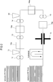
- HDF boards are processed.
- the HDF raw plates are singulated and the surface of the HDF plate is ground in a grinding machine 1.
- the plates are preheated in an IR dryer 2 to a temperature of about 45 ° C.
- the coating resin used is an aqueous melamine-formaldehyde resin having a solids content of 60% by weight.
- a water-based white primer based on casein and inorganic pigments is applied by means of four application units 5 and dried by hot air after each application in a convection dryer 6.
- the individual commissioned works 5 apply different amounts of primer.
- the total white application varies depending on the pressure requirement between 20 g / m 2 and 30 g / m 2 .
- a primer application 7 followed by drying in a further convection dryer 8.
- printing 9 decoration of the plates in indirect gravure printing.
- a decorative layer is first printed with colored pigments followed by a further decorative layer, which has the gas-filled microspheres.
- the plates After printing, the plates are coated with melamine-formaldehyde resin 10 (protective layer) and also dried in a convection dryer 11. Then the plates are stored for a few days before being placed in a second production line ( FIG. 2 ) further processed.
- the primer process is particularly important as it has a significant impact on the color print quality of the coated HDF plates. For a certain color pattern also a constant amount of white order must be guaranteed, as it would otherwise for Different brightnesses of the primer and thus can also come to different colors within a color pattern over several plates.
- the in the FIG. 2 schematically illustrated second production line comprises four double application units 12, 13, 14, 15 for simultaneous application of the respective resin layer on the top and bottom of the individual printed material plates eg of printed HDF plates and four arranged in the processing direction behind the double application units convection dryer 12a, 13a, 14a, 15a.
- a first spreader 10 is also provided for uniformly spreading the abrasion resistant material such as e.g. Corundum provided on the first resin layer on top of the HDF board. The drying of the first resin layer then takes place in the first convection dryer 12a.
- the third double applicator 14 for applying the third resin layer may be followed by a further diffuser 20 for applying glass beads to the third resin layer, followed by a third convection dryer 14a for drying the third resin layer.
- the diffuser 20 for the glass beads is optional.
- the glass beads can also be applied together with the third resin layer.
- the layer structure is pressed in a short-cycle press 16.
- the pressed plates are cooled and stored.
- a wood decor was applied in digital printing. It was a four-color print (CMYK).
- the printing inks had water as solvent.
- a transparent ink was applied. This was coupled via the software to the black (K).
- the printing ink contained in addition to the solvent, glycol and the binder still microspheres (about 0.6% by weight). About 0.7 g / m 2 of this printing ink was printed, whereby the coupling to the black ensured that this printing ink was in the same areas as the pore color.
- the printed plate was further processed as in the above-described method. After pressing the plate, it was found that a degree of gloss difference from the surface had formed in the area of the structuring due to the expansion of the microspheres.
Landscapes
- Laminated Bodies (AREA)
- Application Of Or Painting With Fluid Materials (AREA)
Priority Applications (3)
| Application Number | Priority Date | Filing Date | Title |
|---|---|---|---|
| ES19150790T ES2770615T3 (es) | 2017-01-20 | 2017-01-20 | Procedimiento para la fabricación de un tablero de material provisto de una capa decorativa |
| PL19150790T PL3489032T3 (pl) | 2017-01-20 | 2017-01-20 | Sposób produkcji płyty z tworzywa z warstwą dekoru |
| EP19150790.4A EP3489032B1 (fr) | 2017-01-20 | 2017-01-20 | Procédé de fabrication d'une plaque de matière pourvue d'une couche décorative |
Applications Claiming Priority (2)
| Application Number | Priority Date | Filing Date | Title |
|---|---|---|---|
| EP19150790.4A EP3489032B1 (fr) | 2017-01-20 | 2017-01-20 | Procédé de fabrication d'une plaque de matière pourvue d'une couche décorative |
| EP17152342.6A EP3351402B1 (fr) | 2017-01-20 | 2017-01-20 | Procédé de production d'une plaque de matériau pourvue d'une couche décorative |
Related Parent Applications (2)
| Application Number | Title | Priority Date | Filing Date |
|---|---|---|---|
| EP17152342.6A Division EP3351402B1 (fr) | 2017-01-20 | 2017-01-20 | Procédé de production d'une plaque de matériau pourvue d'une couche décorative |
| EP17152342.6A Division-Into EP3351402B1 (fr) | 2017-01-20 | 2017-01-20 | Procédé de production d'une plaque de matériau pourvue d'une couche décorative |
Publications (2)
| Publication Number | Publication Date |
|---|---|
| EP3489032A1 true EP3489032A1 (fr) | 2019-05-29 |
| EP3489032B1 EP3489032B1 (fr) | 2019-12-11 |
Family
ID=57868083
Family Applications (2)
| Application Number | Title | Priority Date | Filing Date |
|---|---|---|---|
| EP17152342.6A Active EP3351402B1 (fr) | 2017-01-20 | 2017-01-20 | Procédé de production d'une plaque de matériau pourvue d'une couche décorative |
| EP19150790.4A Active EP3489032B1 (fr) | 2017-01-20 | 2017-01-20 | Procédé de fabrication d'une plaque de matière pourvue d'une couche décorative |
Family Applications Before (1)
| Application Number | Title | Priority Date | Filing Date |
|---|---|---|---|
| EP17152342.6A Active EP3351402B1 (fr) | 2017-01-20 | 2017-01-20 | Procédé de production d'une plaque de matériau pourvue d'une couche décorative |
Country Status (3)
| Country | Link |
|---|---|
| EP (2) | EP3351402B1 (fr) |
| ES (2) | ES2770615T3 (fr) |
| PL (2) | PL3351402T3 (fr) |
Families Citing this family (5)
| Publication number | Priority date | Publication date | Assignee | Title |
|---|---|---|---|---|
| PT3246175T (pt) | 2016-05-20 | 2018-10-22 | Flooring Technologies Ltd | Processo para a produção de uma placa de derivados de madeira resistente à abrasão e linha de produção para a mesma |
| PT3480030T (pt) | 2017-11-06 | 2020-07-21 | Flooring Technologies Ltd | Processo para o fabrico de um painel de derivado da madeira resistente ao desgaste e linha de produção para o mesmo |
| PL3686028T3 (pl) | 2019-01-22 | 2021-10-25 | Flooring Technologies Ltd. | Sposób wytwarzania odpornej na ścieranie płyty drewnopochodnej |
| US20220161586A1 (en) * | 2019-03-06 | 2022-05-26 | Axalta Coating Systems Ip Co., Llc | Controlled surface wetting resulting in improved digital print edge acuity and resolution |
| PL3888933T3 (pl) | 2019-05-13 | 2022-07-25 | Flooring Technologies Ltd. | Sposób wytwarzania płyty drewnopochodnej wyposażonej w dekor |
Citations (5)
| Publication number | Priority date | Publication date | Assignee | Title |
|---|---|---|---|---|
| US4006273A (en) * | 1975-02-03 | 1977-02-01 | Pratt & Lambert, Inc. | Washable and dry-cleanable raised printing on fabrics |
| EP1053382A1 (fr) * | 1998-02-06 | 2000-11-22 | MDF Inc. | Porte a revetement plat imitant une porte a revetement moule tridimensionnel, et procede correspondant |
| US20030096058A1 (en) * | 2001-11-20 | 2003-05-22 | Thomas Wirycz | Design effect fiberglass wallcoverings |
| EP1997623A1 (fr) * | 2007-05-30 | 2008-12-03 | Flooring Technologies Ltd. | Plaque en bois et procédé de fabrication |
| EP2338693A1 (fr) * | 2009-12-23 | 2011-06-29 | Flooring Technologies Ltd. | Procédé et dispositif destinés à l'affinement d'une plaque en matériau dérivé du bois |
-
2017
- 2017-01-20 ES ES19150790T patent/ES2770615T3/es active Active
- 2017-01-20 PL PL17152342T patent/PL3351402T3/pl unknown
- 2017-01-20 PL PL19150790T patent/PL3489032T3/pl unknown
- 2017-01-20 ES ES17152342T patent/ES2730549T3/es active Active
- 2017-01-20 EP EP17152342.6A patent/EP3351402B1/fr active Active
- 2017-01-20 EP EP19150790.4A patent/EP3489032B1/fr active Active
Patent Citations (5)
| Publication number | Priority date | Publication date | Assignee | Title |
|---|---|---|---|---|
| US4006273A (en) * | 1975-02-03 | 1977-02-01 | Pratt & Lambert, Inc. | Washable and dry-cleanable raised printing on fabrics |
| EP1053382A1 (fr) * | 1998-02-06 | 2000-11-22 | MDF Inc. | Porte a revetement plat imitant une porte a revetement moule tridimensionnel, et procede correspondant |
| US20030096058A1 (en) * | 2001-11-20 | 2003-05-22 | Thomas Wirycz | Design effect fiberglass wallcoverings |
| EP1997623A1 (fr) * | 2007-05-30 | 2008-12-03 | Flooring Technologies Ltd. | Plaque en bois et procédé de fabrication |
| EP2338693A1 (fr) * | 2009-12-23 | 2011-06-29 | Flooring Technologies Ltd. | Procédé et dispositif destinés à l'affinement d'une plaque en matériau dérivé du bois |
Non-Patent Citations (1)
| Title |
|---|
| -: "Expandable microsphere", 4 July 2016 (2016-07-04), XP055388156, Retrieved from the Internet <URL:https://en.wikipedia.org/api/rest_v1/page/pdf/Expandable_microsphere> [retrieved on 20170705] * |
Also Published As
| Publication number | Publication date |
|---|---|
| ES2770615T3 (es) | 2020-07-02 |
| PL3351402T3 (pl) | 2019-09-30 |
| EP3489032B1 (fr) | 2019-12-11 |
| PL3489032T3 (pl) | 2020-07-13 |
| EP3351402B1 (fr) | 2019-04-17 |
| ES2730549T3 (es) | 2019-11-11 |
| EP3351402A1 (fr) | 2018-07-25 |
Similar Documents
| Publication | Publication Date | Title |
|---|---|---|
| EP3351402B1 (fr) | Procédé de production d'une plaque de matériau pourvue d'une couche décorative | |
| EP3109056B1 (fr) | Procede et dispositif de fabrication d'une structure sur une surface | |
| EP3246175B1 (fr) | Procédé de fabrication d'une plaque en matériau de type bois et ligne de production pour celle-ci | |
| DE102009044802B4 (de) | Verfahren und Vorrichtung zur Erzeugung einer dreidimensionalen Oberflächenstruktur auf einem Werkstück | |
| WO2018229169A1 (fr) | Procédé et dispositif pour la fabrication d'une pièce décorative et pièce | |
| DE102010010784C5 (de) | Verfahren und Vorrichtung zur Herstellung eines plattenförmigen Produktes mit einer ein Dekor aufweisenden Oberfläche | |
| EP3888933B1 (fr) | Procédé de fabrication d'une plaque en matière dérivée du bois dotée d'un décor | |
| EP3415318B1 (fr) | Procédé et dispositif de fabrication d'une pièce à usiner décorative et pièce à usiner | |
| EP3532300A1 (fr) | Procédé de fabrication d'un panneau mural ou de sol décoré | |
| EP3140130A1 (fr) | Procédé de fabrication de panneaux dérivés du bois décorés et lambris, en particulier lambris de plancher, fabriqué à partir de panneaux dérivés du bois, et utilisation d'un panneau dérivé du bois fabriqué par ce procédé | |
| EP3914459A1 (fr) | Procédé pour la fabrication d'un panneau de bois résistant à l'abrasion | |
| EP3059020B1 (fr) | Procédé de fabrication d'une plaque en dérivé de bois, notamment d'une plaque en dérivé de bois dotée d'une couche décorative | |
| EP3707007B1 (fr) | Procédé de fabrication d'un panneau résistant à l'usure au matériau dérivé du bois et ligne de production correspondante | |
| DE102017113036A1 (de) | Verfahren und Vorrichtung zur Herstellung eines dekorativen Werkstückes und Werkstück | |
| EP4094848B1 (fr) | Procede de fabrication d'un stratifie resistant a l'abrasion | |
| EP4134242B1 (fr) | Procédé et dispositif d'application d'un décor et d'une structure de surface sur une matière porteuse | |
| EP3597312B1 (fr) | Procédé de fabrication d'un panneau à particules orientées pourvu d'une surface imprimée |
Legal Events
| Date | Code | Title | Description |
|---|---|---|---|
| PUAI | Public reference made under article 153(3) epc to a published international application that has entered the european phase |
Free format text: ORIGINAL CODE: 0009012 |
|
| STAA | Information on the status of an ep patent application or granted ep patent |
Free format text: STATUS: THE APPLICATION HAS BEEN PUBLISHED |
|
| STAA | Information on the status of an ep patent application or granted ep patent |
Free format text: STATUS: REQUEST FOR EXAMINATION WAS MADE |
|
| AC | Divisional application: reference to earlier application |
Ref document number: 3351402 Country of ref document: EP Kind code of ref document: P |
|
| AK | Designated contracting states |
Kind code of ref document: A1 Designated state(s): AL AT BE BG CH CY CZ DE DK EE ES FI FR GB GR HR HU IE IS IT LI LT LU LV MC MK MT NL NO PL PT RO RS SE SI SK SM TR |
|
| AX | Request for extension of the european patent |
Extension state: BA ME |
|
| 17P | Request for examination filed |
Effective date: 20190509 |
|
| RBV | Designated contracting states (corrected) |
Designated state(s): AL AT BE BG CH CY CZ DE DK EE ES FI FR GB GR HR HU IE IS IT LI LT LU LV MC MK MT NL NO PL PT RO RS SE SI SK SM TR |
|
| GRAP | Despatch of communication of intention to grant a patent |
Free format text: ORIGINAL CODE: EPIDOSNIGR1 |
|
| STAA | Information on the status of an ep patent application or granted ep patent |
Free format text: STATUS: GRANT OF PATENT IS INTENDED |
|
| RIC1 | Information provided on ipc code assigned before grant |
Ipc: B44C 5/04 20060101AFI20190626BHEP |
|
| INTG | Intention to grant announced |
Effective date: 20190725 |
|
| GRAS | Grant fee paid |
Free format text: ORIGINAL CODE: EPIDOSNIGR3 |
|
| GRAA | (expected) grant |
Free format text: ORIGINAL CODE: 0009210 |
|
| STAA | Information on the status of an ep patent application or granted ep patent |
Free format text: STATUS: THE PATENT HAS BEEN GRANTED |
|
| AC | Divisional application: reference to earlier application |
Ref document number: 3351402 Country of ref document: EP Kind code of ref document: P |
|
| AK | Designated contracting states |
Kind code of ref document: B1 Designated state(s): AL AT BE BG CH CY CZ DE DK EE ES FI FR GB GR HR HU IE IS IT LI LT LU LV MC MK MT NL NO PL PT RO RS SE SI SK SM TR |
|
| REG | Reference to a national code |
Ref country code: GB Ref legal event code: FG4D Free format text: NOT ENGLISH |
|
| REG | Reference to a national code |
Ref country code: CH Ref legal event code: EP |
|
| REG | Reference to a national code |
Ref country code: AT Ref legal event code: REF Ref document number: 1211812 Country of ref document: AT Kind code of ref document: T Effective date: 20191215 |
|
| REG | Reference to a national code |
Ref country code: DE Ref legal event code: R096 Ref document number: 502017003137 Country of ref document: DE |
|
| REG | Reference to a national code |
Ref country code: IE Ref legal event code: FG4D Free format text: LANGUAGE OF EP DOCUMENT: GERMAN |
|
| REG | Reference to a national code |
Ref country code: CH Ref legal event code: NV Representative=s name: SCHMAUDER AND PARTNER AG PATENT- UND MARKENANW, CH |
|
| REG | Reference to a national code |
Ref country code: LT Ref legal event code: MG4D |
|
| PG25 | Lapsed in a contracting state [announced via postgrant information from national office to epo] |
Ref country code: LT Free format text: LAPSE BECAUSE OF FAILURE TO SUBMIT A TRANSLATION OF THE DESCRIPTION OR TO PAY THE FEE WITHIN THE PRESCRIBED TIME-LIMIT Effective date: 20191211 Ref country code: NO Free format text: LAPSE BECAUSE OF FAILURE TO SUBMIT A TRANSLATION OF THE DESCRIPTION OR TO PAY THE FEE WITHIN THE PRESCRIBED TIME-LIMIT Effective date: 20200311 Ref country code: SE Free format text: LAPSE BECAUSE OF FAILURE TO SUBMIT A TRANSLATION OF THE DESCRIPTION OR TO PAY THE FEE WITHIN THE PRESCRIBED TIME-LIMIT Effective date: 20191211 Ref country code: LV Free format text: LAPSE BECAUSE OF FAILURE TO SUBMIT A TRANSLATION OF THE DESCRIPTION OR TO PAY THE FEE WITHIN THE PRESCRIBED TIME-LIMIT Effective date: 20191211 Ref country code: FI Free format text: LAPSE BECAUSE OF FAILURE TO SUBMIT A TRANSLATION OF THE DESCRIPTION OR TO PAY THE FEE WITHIN THE PRESCRIBED TIME-LIMIT Effective date: 20191211 Ref country code: BG Free format text: LAPSE BECAUSE OF FAILURE TO SUBMIT A TRANSLATION OF THE DESCRIPTION OR TO PAY THE FEE WITHIN THE PRESCRIBED TIME-LIMIT Effective date: 20200311 |
|
| REG | Reference to a national code |
Ref country code: NL Ref legal event code: FP |
|
| PG25 | Lapsed in a contracting state [announced via postgrant information from national office to epo] |
Ref country code: RS Free format text: LAPSE BECAUSE OF FAILURE TO SUBMIT A TRANSLATION OF THE DESCRIPTION OR TO PAY THE FEE WITHIN THE PRESCRIBED TIME-LIMIT Effective date: 20191211 Ref country code: HR Free format text: LAPSE BECAUSE OF FAILURE TO SUBMIT A TRANSLATION OF THE DESCRIPTION OR TO PAY THE FEE WITHIN THE PRESCRIBED TIME-LIMIT Effective date: 20191211 |
|
| PG25 | Lapsed in a contracting state [announced via postgrant information from national office to epo] |
Ref country code: AL Free format text: LAPSE BECAUSE OF FAILURE TO SUBMIT A TRANSLATION OF THE DESCRIPTION OR TO PAY THE FEE WITHIN THE PRESCRIBED TIME-LIMIT Effective date: 20191211 |
|
| REG | Reference to a national code |
Ref country code: ES Ref legal event code: FG2A Ref document number: 2770615 Country of ref document: ES Kind code of ref document: T3 Effective date: 20200702 |
|
| PG25 | Lapsed in a contracting state [announced via postgrant information from national office to epo] |
Ref country code: RO Free format text: LAPSE BECAUSE OF FAILURE TO SUBMIT A TRANSLATION OF THE DESCRIPTION OR TO PAY THE FEE WITHIN THE PRESCRIBED TIME-LIMIT Effective date: 20191211 Ref country code: EE Free format text: LAPSE BECAUSE OF FAILURE TO SUBMIT A TRANSLATION OF THE DESCRIPTION OR TO PAY THE FEE WITHIN THE PRESCRIBED TIME-LIMIT Effective date: 20191211 Ref country code: CZ Free format text: LAPSE BECAUSE OF FAILURE TO SUBMIT A TRANSLATION OF THE DESCRIPTION OR TO PAY THE FEE WITHIN THE PRESCRIBED TIME-LIMIT Effective date: 20191211 Ref country code: PT Free format text: LAPSE BECAUSE OF FAILURE TO SUBMIT A TRANSLATION OF THE DESCRIPTION OR TO PAY THE FEE WITHIN THE PRESCRIBED TIME-LIMIT Effective date: 20200506 |
|
| PG25 | Lapsed in a contracting state [announced via postgrant information from national office to epo] |
Ref country code: SK Free format text: LAPSE BECAUSE OF FAILURE TO SUBMIT A TRANSLATION OF THE DESCRIPTION OR TO PAY THE FEE WITHIN THE PRESCRIBED TIME-LIMIT Effective date: 20191211 Ref country code: SM Free format text: LAPSE BECAUSE OF FAILURE TO SUBMIT A TRANSLATION OF THE DESCRIPTION OR TO PAY THE FEE WITHIN THE PRESCRIBED TIME-LIMIT Effective date: 20191211 Ref country code: IS Free format text: LAPSE BECAUSE OF FAILURE TO SUBMIT A TRANSLATION OF THE DESCRIPTION OR TO PAY THE FEE WITHIN THE PRESCRIBED TIME-LIMIT Effective date: 20200411 |
|
| REG | Reference to a national code |
Ref country code: DE Ref legal event code: R097 Ref document number: 502017003137 Country of ref document: DE |
|
| PG25 | Lapsed in a contracting state [announced via postgrant information from national office to epo] |
Ref country code: MC Free format text: LAPSE BECAUSE OF FAILURE TO SUBMIT A TRANSLATION OF THE DESCRIPTION OR TO PAY THE FEE WITHIN THE PRESCRIBED TIME-LIMIT Effective date: 20191211 |
|
| PLBE | No opposition filed within time limit |
Free format text: ORIGINAL CODE: 0009261 |
|
| STAA | Information on the status of an ep patent application or granted ep patent |
Free format text: STATUS: NO OPPOSITION FILED WITHIN TIME LIMIT |
|
| PG25 | Lapsed in a contracting state [announced via postgrant information from national office to epo] |
Ref country code: DK Free format text: LAPSE BECAUSE OF FAILURE TO SUBMIT A TRANSLATION OF THE DESCRIPTION OR TO PAY THE FEE WITHIN THE PRESCRIBED TIME-LIMIT Effective date: 20191211 Ref country code: LU Free format text: LAPSE BECAUSE OF NON-PAYMENT OF DUE FEES Effective date: 20200120 |
|
| 26N | No opposition filed |
Effective date: 20200914 |
|
| PG25 | Lapsed in a contracting state [announced via postgrant information from national office to epo] |
Ref country code: IE Free format text: LAPSE BECAUSE OF NON-PAYMENT OF DUE FEES Effective date: 20200120 |
|
| PG25 | Lapsed in a contracting state [announced via postgrant information from national office to epo] |
Ref country code: MT Free format text: LAPSE BECAUSE OF FAILURE TO SUBMIT A TRANSLATION OF THE DESCRIPTION OR TO PAY THE FEE WITHIN THE PRESCRIBED TIME-LIMIT Effective date: 20191211 Ref country code: CY Free format text: LAPSE BECAUSE OF FAILURE TO SUBMIT A TRANSLATION OF THE DESCRIPTION OR TO PAY THE FEE WITHIN THE PRESCRIBED TIME-LIMIT Effective date: 20191211 |
|
| PG25 | Lapsed in a contracting state [announced via postgrant information from national office to epo] |
Ref country code: MK Free format text: LAPSE BECAUSE OF FAILURE TO SUBMIT A TRANSLATION OF THE DESCRIPTION OR TO PAY THE FEE WITHIN THE PRESCRIBED TIME-LIMIT Effective date: 20191211 |
|
| PG25 | Lapsed in a contracting state [announced via postgrant information from national office to epo] |
Ref country code: GR Free format text: LAPSE BECAUSE OF FAILURE TO SUBMIT A TRANSLATION OF THE DESCRIPTION OR TO PAY THE FEE WITHIN THE PRESCRIBED TIME-LIMIT Effective date: 20191211 |
|
| PGFP | Annual fee paid to national office [announced via postgrant information from national office to epo] |
Ref country code: FR Payment date: 20230123 Year of fee payment: 7 Ref country code: ES Payment date: 20230216 Year of fee payment: 7 Ref country code: CH Payment date: 20230130 Year of fee payment: 7 Ref country code: AT Payment date: 20230118 Year of fee payment: 7 |
|
| PGFP | Annual fee paid to national office [announced via postgrant information from national office to epo] |
Ref country code: TR Payment date: 20230118 Year of fee payment: 7 Ref country code: IT Payment date: 20230131 Year of fee payment: 7 Ref country code: GB Payment date: 20230124 Year of fee payment: 7 Ref country code: DE Payment date: 20221230 Year of fee payment: 7 Ref country code: BE Payment date: 20230123 Year of fee payment: 7 |
|
| PG25 | Lapsed in a contracting state [announced via postgrant information from national office to epo] |
Ref country code: SI Free format text: LAPSE BECAUSE OF FAILURE TO SUBMIT A TRANSLATION OF THE DESCRIPTION OR TO PAY THE FEE WITHIN THE PRESCRIBED TIME-LIMIT Effective date: 20191211 |
|
| PGFP | Annual fee paid to national office [announced via postgrant information from national office to epo] |
Ref country code: PL Payment date: 20231218 Year of fee payment: 8 Ref country code: NL Payment date: 20240123 Year of fee payment: 8 |
|
| PGFP | Annual fee paid to national office [announced via postgrant information from national office to epo] |
Ref country code: ES Payment date: 20240216 Year of fee payment: 8 |
|
| PGFP | Annual fee paid to national office [announced via postgrant information from national office to epo] |
Ref country code: AT Payment date: 20240118 Year of fee payment: 8 |
|
| PGFP | Annual fee paid to national office [announced via postgrant information from national office to epo] |
Ref country code: DE Payment date: 20240109 Year of fee payment: 8 Ref country code: GB Payment date: 20240124 Year of fee payment: 8 Ref country code: CH Payment date: 20240202 Year of fee payment: 8 |