EP3488987A1 - Method and device for batched compression molding of rubber and plastic products by means of multiple mold cavities - Google Patents
Method and device for batched compression molding of rubber and plastic products by means of multiple mold cavities Download PDFInfo
- Publication number
- EP3488987A1 EP3488987A1 EP17873442.2A EP17873442A EP3488987A1 EP 3488987 A1 EP3488987 A1 EP 3488987A1 EP 17873442 A EP17873442 A EP 17873442A EP 3488987 A1 EP3488987 A1 EP 3488987A1
- Authority
- EP
- European Patent Office
- Prior art keywords
- mold
- blank
- compression molding
- incomplete gear
- cable
- Prior art date
- Legal status (The legal status is an assumption and is not a legal conclusion. Google has not performed a legal analysis and makes no representation as to the accuracy of the status listed.)
- Granted
Links
Images

Classifications
-
- B—PERFORMING OPERATIONS; TRANSPORTING
- B29—WORKING OF PLASTICS; WORKING OF SUBSTANCES IN A PLASTIC STATE IN GENERAL
- B29C—SHAPING OR JOINING OF PLASTICS; SHAPING OF MATERIAL IN A PLASTIC STATE, NOT OTHERWISE PROVIDED FOR; AFTER-TREATMENT OF THE SHAPED PRODUCTS, e.g. REPAIRING
- B29C43/00—Compression moulding, i.e. applying external pressure to flow the moulding material; Apparatus therefor
- B29C43/32—Component parts, details or accessories; Auxiliary operations
- B29C43/36—Moulds for making articles of definite length, i.e. discrete articles
- B29C43/361—Moulds for making articles of definite length, i.e. discrete articles with pressing members independently movable of the parts for opening or closing the mould, e.g. movable pistons
-
- B—PERFORMING OPERATIONS; TRANSPORTING
- B29—WORKING OF PLASTICS; WORKING OF SUBSTANCES IN A PLASTIC STATE IN GENERAL
- B29C—SHAPING OR JOINING OF PLASTICS; SHAPING OF MATERIAL IN A PLASTIC STATE, NOT OTHERWISE PROVIDED FOR; AFTER-TREATMENT OF THE SHAPED PRODUCTS, e.g. REPAIRING
- B29C43/00—Compression moulding, i.e. applying external pressure to flow the moulding material; Apparatus therefor
- B29C43/32—Component parts, details or accessories; Auxiliary operations
-
- B—PERFORMING OPERATIONS; TRANSPORTING
- B29—WORKING OF PLASTICS; WORKING OF SUBSTANCES IN A PLASTIC STATE IN GENERAL
- B29C—SHAPING OR JOINING OF PLASTICS; SHAPING OF MATERIAL IN A PLASTIC STATE, NOT OTHERWISE PROVIDED FOR; AFTER-TREATMENT OF THE SHAPED PRODUCTS, e.g. REPAIRING
- B29C43/00—Compression moulding, i.e. applying external pressure to flow the moulding material; Apparatus therefor
- B29C43/02—Compression moulding, i.e. applying external pressure to flow the moulding material; Apparatus therefor of articles of definite length, i.e. discrete articles
-
- B—PERFORMING OPERATIONS; TRANSPORTING
- B29—WORKING OF PLASTICS; WORKING OF SUBSTANCES IN A PLASTIC STATE IN GENERAL
- B29C—SHAPING OR JOINING OF PLASTICS; SHAPING OF MATERIAL IN A PLASTIC STATE, NOT OTHERWISE PROVIDED FOR; AFTER-TREATMENT OF THE SHAPED PRODUCTS, e.g. REPAIRING
- B29C43/00—Compression moulding, i.e. applying external pressure to flow the moulding material; Apparatus therefor
- B29C43/02—Compression moulding, i.e. applying external pressure to flow the moulding material; Apparatus therefor of articles of definite length, i.e. discrete articles
- B29C43/10—Isostatic pressing, i.e. using non-rigid pressure-exerting members against rigid parts or dies
-
- B—PERFORMING OPERATIONS; TRANSPORTING
- B29—WORKING OF PLASTICS; WORKING OF SUBSTANCES IN A PLASTIC STATE IN GENERAL
- B29C—SHAPING OR JOINING OF PLASTICS; SHAPING OF MATERIAL IN A PLASTIC STATE, NOT OTHERWISE PROVIDED FOR; AFTER-TREATMENT OF THE SHAPED PRODUCTS, e.g. REPAIRING
- B29C43/00—Compression moulding, i.e. applying external pressure to flow the moulding material; Apparatus therefor
- B29C43/32—Component parts, details or accessories; Auxiliary operations
- B29C43/34—Feeding the material to the mould or the compression means
-
- B—PERFORMING OPERATIONS; TRANSPORTING
- B29—WORKING OF PLASTICS; WORKING OF SUBSTANCES IN A PLASTIC STATE IN GENERAL
- B29C—SHAPING OR JOINING OF PLASTICS; SHAPING OF MATERIAL IN A PLASTIC STATE, NOT OTHERWISE PROVIDED FOR; AFTER-TREATMENT OF THE SHAPED PRODUCTS, e.g. REPAIRING
- B29C43/00—Compression moulding, i.e. applying external pressure to flow the moulding material; Apparatus therefor
- B29C43/32—Component parts, details or accessories; Auxiliary operations
- B29C43/44—Compression means for making articles of indefinite length
- B29C43/46—Rollers
-
- B—PERFORMING OPERATIONS; TRANSPORTING
- B29—WORKING OF PLASTICS; WORKING OF SUBSTANCES IN A PLASTIC STATE IN GENERAL
- B29C—SHAPING OR JOINING OF PLASTICS; SHAPING OF MATERIAL IN A PLASTIC STATE, NOT OTHERWISE PROVIDED FOR; AFTER-TREATMENT OF THE SHAPED PRODUCTS, e.g. REPAIRING
- B29C43/00—Compression moulding, i.e. applying external pressure to flow the moulding material; Apparatus therefor
- B29C43/32—Component parts, details or accessories; Auxiliary operations
- B29C43/50—Removing moulded articles
-
- B—PERFORMING OPERATIONS; TRANSPORTING
- B29—WORKING OF PLASTICS; WORKING OF SUBSTANCES IN A PLASTIC STATE IN GENERAL
- B29C—SHAPING OR JOINING OF PLASTICS; SHAPING OF MATERIAL IN A PLASTIC STATE, NOT OTHERWISE PROVIDED FOR; AFTER-TREATMENT OF THE SHAPED PRODUCTS, e.g. REPAIRING
- B29C43/00—Compression moulding, i.e. applying external pressure to flow the moulding material; Apparatus therefor
- B29C43/32—Component parts, details or accessories; Auxiliary operations
- B29C43/58—Measuring, controlling or regulating
-
- B—PERFORMING OPERATIONS; TRANSPORTING
- B30—PRESSES
- B30B—PRESSES IN GENERAL
- B30B1/00—Presses, using a press ram, characterised by the features of the drive therefor, pressure being transmitted directly, or through simple thrust or tension members only, to the press ram or platen
- B30B1/02—Presses, using a press ram, characterised by the features of the drive therefor, pressure being transmitted directly, or through simple thrust or tension members only, to the press ram or platen by lever mechanism
-
- B—PERFORMING OPERATIONS; TRANSPORTING
- B30—PRESSES
- B30B—PRESSES IN GENERAL
- B30B15/00—Details of, or accessories for, presses; Auxiliary measures in connection with pressing
- B30B15/30—Feeding material to presses
- B30B15/302—Feeding material in particulate or plastic state to moulding presses
-
- B—PERFORMING OPERATIONS; TRANSPORTING
- B30—PRESSES
- B30B—PRESSES IN GENERAL
- B30B15/00—Details of, or accessories for, presses; Auxiliary measures in connection with pressing
- B30B15/30—Feeding material to presses
- B30B15/302—Feeding material in particulate or plastic state to moulding presses
- B30B15/304—Feeding material in particulate or plastic state to moulding presses by using feed frames or shoes with relative movement with regard to the mould or moulds
-
- B—PERFORMING OPERATIONS; TRANSPORTING
- B30—PRESSES
- B30B—PRESSES IN GENERAL
- B30B15/00—Details of, or accessories for, presses; Auxiliary measures in connection with pressing
- B30B15/32—Discharging presses
-
- B—PERFORMING OPERATIONS; TRANSPORTING
- B29—WORKING OF PLASTICS; WORKING OF SUBSTANCES IN A PLASTIC STATE IN GENERAL
- B29C—SHAPING OR JOINING OF PLASTICS; SHAPING OF MATERIAL IN A PLASTIC STATE, NOT OTHERWISE PROVIDED FOR; AFTER-TREATMENT OF THE SHAPED PRODUCTS, e.g. REPAIRING
- B29C43/00—Compression moulding, i.e. applying external pressure to flow the moulding material; Apparatus therefor
- B29C43/32—Component parts, details or accessories; Auxiliary operations
- B29C2043/3272—Component parts, details or accessories; Auxiliary operations driving means
-
- B—PERFORMING OPERATIONS; TRANSPORTING
- B29—WORKING OF PLASTICS; WORKING OF SUBSTANCES IN A PLASTIC STATE IN GENERAL
- B29C—SHAPING OR JOINING OF PLASTICS; SHAPING OF MATERIAL IN A PLASTIC STATE, NOT OTHERWISE PROVIDED FOR; AFTER-TREATMENT OF THE SHAPED PRODUCTS, e.g. REPAIRING
- B29C43/00—Compression moulding, i.e. applying external pressure to flow the moulding material; Apparatus therefor
- B29C43/32—Component parts, details or accessories; Auxiliary operations
- B29C2043/3272—Component parts, details or accessories; Auxiliary operations driving means
- B29C2043/3283—Component parts, details or accessories; Auxiliary operations driving means for moving moulds or mould parts
-
- B—PERFORMING OPERATIONS; TRANSPORTING
- B29—WORKING OF PLASTICS; WORKING OF SUBSTANCES IN A PLASTIC STATE IN GENERAL
- B29C—SHAPING OR JOINING OF PLASTICS; SHAPING OF MATERIAL IN A PLASTIC STATE, NOT OTHERWISE PROVIDED FOR; AFTER-TREATMENT OF THE SHAPED PRODUCTS, e.g. REPAIRING
- B29C43/00—Compression moulding, i.e. applying external pressure to flow the moulding material; Apparatus therefor
- B29C43/32—Component parts, details or accessories; Auxiliary operations
- B29C43/34—Feeding the material to the mould or the compression means
- B29C2043/3405—Feeding the material to the mould or the compression means using carrying means
-
- B—PERFORMING OPERATIONS; TRANSPORTING
- B29—WORKING OF PLASTICS; WORKING OF SUBSTANCES IN A PLASTIC STATE IN GENERAL
- B29C—SHAPING OR JOINING OF PLASTICS; SHAPING OF MATERIAL IN A PLASTIC STATE, NOT OTHERWISE PROVIDED FOR; AFTER-TREATMENT OF THE SHAPED PRODUCTS, e.g. REPAIRING
- B29C43/00—Compression moulding, i.e. applying external pressure to flow the moulding material; Apparatus therefor
- B29C43/32—Component parts, details or accessories; Auxiliary operations
- B29C43/36—Moulds for making articles of definite length, i.e. discrete articles
- B29C43/361—Moulds for making articles of definite length, i.e. discrete articles with pressing members independently movable of the parts for opening or closing the mould, e.g. movable pistons
- B29C2043/3615—Forming elements, e.g. mandrels or rams or stampers or pistons or plungers or punching devices
-
- B—PERFORMING OPERATIONS; TRANSPORTING
- B29—WORKING OF PLASTICS; WORKING OF SUBSTANCES IN A PLASTIC STATE IN GENERAL
- B29C—SHAPING OR JOINING OF PLASTICS; SHAPING OF MATERIAL IN A PLASTIC STATE, NOT OTHERWISE PROVIDED FOR; AFTER-TREATMENT OF THE SHAPED PRODUCTS, e.g. REPAIRING
- B29C43/00—Compression moulding, i.e. applying external pressure to flow the moulding material; Apparatus therefor
- B29C43/32—Component parts, details or accessories; Auxiliary operations
- B29C43/50—Removing moulded articles
- B29C2043/503—Removing moulded articles using ejector pins, rods
-
- B—PERFORMING OPERATIONS; TRANSPORTING
- B29—WORKING OF PLASTICS; WORKING OF SUBSTANCES IN A PLASTIC STATE IN GENERAL
- B29C—SHAPING OR JOINING OF PLASTICS; SHAPING OF MATERIAL IN A PLASTIC STATE, NOT OTHERWISE PROVIDED FOR; AFTER-TREATMENT OF THE SHAPED PRODUCTS, e.g. REPAIRING
- B29C43/00—Compression moulding, i.e. applying external pressure to flow the moulding material; Apparatus therefor
- B29C43/32—Component parts, details or accessories; Auxiliary operations
- B29C43/58—Measuring, controlling or regulating
- B29C2043/5833—Measuring, controlling or regulating movement of moulds or mould parts, e.g. opening or closing, actuating
-
- B—PERFORMING OPERATIONS; TRANSPORTING
- B29—WORKING OF PLASTICS; WORKING OF SUBSTANCES IN A PLASTIC STATE IN GENERAL
- B29D—PRODUCING PARTICULAR ARTICLES FROM PLASTICS OR FROM SUBSTANCES IN A PLASTIC STATE
- B29D99/00—Subject matter not provided for in other groups of this subclass
- B29D99/0096—Producing closure members for containers, e.g. closure caps or stoppers
-
- B—PERFORMING OPERATIONS; TRANSPORTING
- B29—WORKING OF PLASTICS; WORKING OF SUBSTANCES IN A PLASTIC STATE IN GENERAL
- B29L—INDEXING SCHEME ASSOCIATED WITH SUBCLASS B29C, RELATING TO PARTICULAR ARTICLES
- B29L2031/00—Other particular articles
- B29L2031/56—Stoppers or lids for bottles, jars, or the like, e.g. closures
Definitions
- the present invention relates to the technical field of rubber and plastic product molding, in particular to a method and device for batched compression molding of rubber and plastic products by means of multiple mold cavities.
- a bottle cap is an important part of food and beverage packaging. It has the function of keeping the contained product sealed, preventing counterfeit and shoddy products, and ensuring that the contained product is not maliciously damaged. Therefore, the bottle cap is widely used in various bottled products and is a key product for bottle container packaging.
- the cap manufacturing industry can be thus regarded as the upstream industry of the food and beverage industry, the chemical industry and the pharmaceutical industry, etc., while changes in the demand of the downstream consumer market will directly affect the development of the upstream industry.
- the food and beverage industry is booming, and the requirements for product packaging are getting higher and higher, which in turn has led to an increasing demand for bottle cap products.
- the production of bottle caps has risen steadily, and so stable and reliable high-efficiency compression molding equipment will have a good application prospect.
- Sacmi an Italian company
- Sacmi is the first mechanical manufacturer to introduce compression molding cap manufacturing equipment to the market and also currently the leader in capping technology.
- a rotary hydraulic press of Sacmi simplifies the mold, making the investment cost of compression molding much less than that of injection molding.
- the capping machine produced by the Italian company of Sacmi can produce up to 72,000 caps per hour.
- a few foreign companies monopolize the manufacturing technology of the compression molding cap manufacturing equipment. Due to various reasons such as mechanical design, engineering materials and production process, there is still a considerable gap between the domestically produced compression molding cap manufacturing equipment and the equipment of the world advanced level. In the domestic market, there are only a few competitive equipment suppliers such as Italian Sacmi. The technical monopoly and no rivals in competition have caused the expensive price of the equipment, while the domestically produced compression molding cap manufacturing equipment generally has problems such as low production efficiency and poor precision and stability, not meeting the current market demand.
- An object of the present invention is to overcome the deficiencies of the prior art and provide a method for batched compression molding of rubber and plastic products by means of multiple mold cavities, so as to solve the general problem such as low production efficiency and poor precision and stability of the existing compression molding cap manufacturing equipment.
- Another object of the present invention is to provide a device for batched compression molding of rubber and plastic products by means of multiple mold cavities for implementing the above method.
- a technical solution of the present invention is as follows: A method for batched compression molding of rubber and plastic products by means of multiple mold cavities is provided; according to the method, alternate operation of a blank shuttle and a male mold that is in a bottle cap mold is controlled by means of engagement of two incomplete gear sets; besides, in the engagement process of the two incomplete gear sets, mold opening motion, isostatic pressing energy storage and spring energy storage are implemented by means of the engagement characteristic of the incomplete gear sets, and fast mold closing and compression molding are implemented by means of the non-engagement characteristic, isostatic pressing energy storage and pressurization of the incomplete gear sets.
- a three-bar linkage mechanism is disposed between the incomplete gear set and the blank shuttle, and the incomplete gear set uses the three-bar linkage mechanism to control the blank shuttle to quickly and synchronously convey a blank to a master mold in the bottle cap mold.
- the blank shuttle and the male mold have the same motion period.
- the two incomplete gear sets are externally connected to the same power source.
- a device for batched compression molding of rubber and plastic products by means of multiple mold cavities of the present invention for implementing the above method comprises a cable transmission mechanism, a three-bar linkage mechanism, a bottle cap mold, a blank shuttle and a male mold supporting plate.
- the cable transmission mechanism comprises two incomplete gear sets, a mold moving rotary winding wheel, a mold moving cable, a blank conveying rotary winding wheel and a blank conveying cable, and the two incomplete gear sets comprise a mold moving incomplete gear set and a blank conveying incomplete gear set.
- the bottle cap mold comprises a male mold and a female mold, a plurality of male molds being evenly distributed on the periphery of the male mold supporting plate, one female mold being arranged under each of the male molds, with one blank shuttle arranged between the male mold and the female mold of each pair.
- the mold moving incomplete gear set and the mold moving rotary winding wheel are connected; the blank conveying incomplete gear set and the blank conveying rotary winding wheel are connected; one end of the mold moving cable is wound on the mold moving rotary winding wheel, and the other end of the mold moving cable is connected with the male mold supporting plate; one end of a blank conveying cable is wound on the blank conveying rotary winding wheel, and the other end of the blank conveying cable is fixedly connected to a blank conveying cable holder; a plurality of three-bar linkage mechanisms are distributed on the blank conveying cable holder, wherein one end of each of the three-bar linkage mechanisms is connected with the blank conveying cable holder, and the other end of each of the three-bar linkage mechanisms is correspondingly connected with one blank shuttle.
- the mold moving incomplete gear set drives the mold moving rotary winding wheel to rotate, so that the mold moving cable is unwound or wound, thereby driving the male mold to move up or down through the male mold supporting plate to realize mold opening or closing.
- the blank conveying incomplete gear set drives the blank conveying rotary winding wheel to rotate (the mold moving rotary winding wheel and the blank conveying rotary winding wheel alternately operate), so that the blank conveying cable is unwound or wound, thereby driving the blank conveying cable holder to move up or down and driving the blank shuttle through the three-bar linkage mechanism to enter into or exit from the lower part of the male mold.
- the blank in the blank shuttle is provided by a feeding device located therebelow.
- a blank-conveying cable-holder supporting column is arranged in the middle of the blank conveying cable holder, and provided with a blank shuttle supporting frame on the lower periphery, with each of the blank shuttles distributed on the blank shuttle supporting frame; the blank conveying cable holder, the blank-conveying cable-holder supporting column and the blank shuttle supporting frame form a blank conveying cable mechanism.
- the blank-conveying cable-holder supporting column is arranged mainly for providing more precise guidance and support for the up and down movement of the blank conveying cable holder, and also for providing guidance and support by using the blank shuttle supporting frame for each of the blank shuttles to enter into or exit from the bottle cap mold.
- a linkage bar supporting holder provided inside with a return spring, is further arranged in the middle of the blank-conveying cable-holder supporting column, and respectively connected with each of the three-bar linkage mechanisms.
- the setting of the linkage bar supporting holder can make the operation of each of the three-bar linkage mechanisms more stable, so that the blank shuttle can be accurately positioned when feeding.
- An ejection plate is arranged in parallel above the male mold supporting plate, and a first mold moving spring is disposed between the ejection plate and the male mold supporting plate.
- the ejection plate is provided on the outer circumference with a plurality of ejection rods, each of which is correspondingly located on one side of one male mold.
- the ejection plate and the first mold moving spring are arranged to realize the spring energy storage while the mold is being opened, and meanwhile the ejection plate provides support for each of the ejection rods, so that the ejection rod can quickly eject the bottle cap product when the mold is opened.
- a mold moving supporting plate is arranged in parallel above the ejection plate, and a second mold moving spring is arranged between the mold moving supporting plate and the ejection plate.
- the male mold supporting plate is provided with a compression molding oil cylinder, whose piston passes through the ejection plate to be located in the second mold moving spring.
- the compression molding oil cylinder is provided at the bottom with a compression molding oil guiding plate and a compression molding switch valve, and a pressure relief oil guiding plate is arranged at the bottom of the compression molding oil guiding plate.
- the mold moving supporting plate is provided with an oil tank
- the male mold supporting plate is provided with an energy storage oil cylinder, with the front drive piston of the energy storage oil cylinder passing through the ejection plate to get connected with the oil tank.
- a pressure relief valve is provided on one side of the energy storage oil cylinder.
- the energy storage oil cylinder can also be externally connected to a pressurized positioning device through the pressure relief valve.
- the pressurized positioning device which has the same specific structure as the existing one in the market, comprises a pressurized positioning bolt, a pressurized positioning spring and a pressurized positioning bolt reset disk, and can be used to control the pressure relief valve to be on/off to limit the front drive piston.
- the above-mentioned method and device for batched compression molding of rubber and plastic products by means of multiple mold cavities has the following principle when used for production:
- the motor as the power source drives the mold moving rotary winding wheel to rotate, and the mold moving cable pulls the male mold supporting plate up to realize the mold opening and at the same time get the bottle cap products ejected.
- the first mold moving spring is compressed to store energy, and the energy storage oil cylinder also stores energy, with the stored energy used for pressurized compression molding and pressure retention during mold closing.
- the blank conveying incomplete gear set is disengaged, and the three-bar linkage mechanism is driven to expand by the blank conveying rotary winding wheel, the blank conveying cable and the blank conveying cable holder, thereby driving the blank shuttle to shuttle out of the bottle cap mold for cutting the blank. Then the blank is blown to the master mold by the gas through a gas conduit inside the blank shuttle, and next the blank shuttle remains stationary until the blank conveying incomplete gear set is re-engaged. When the incomplete gear set is re-engaged, the three-bar linkage mechanism retracts to drive the blank shuttle to shuttle into the bottle cap mold.
- the mold moving incomplete gear set is disengaged, the ejection plate and the male mold supporting plate are moved down respectively by the ejecting force of the first mold moving spring and the second mold moving spring to perform mold closing, and the pressure oil flows from the energy storage oil cylinder into the compression molding oil cylinder for pressurized compression molding and pressure retention until the mold moving incomplete gear set is re-engaged.
- the blank shuttle and the male mold have the same motion period that is generally designed to be 2 s.
- the present invention has the following beneficial effects compared to the prior art: Compared with similar equipment currently imported from abroad, the method and device for batched compression molding of rubber and plastic products by means of multiple mold cavities has lower requirements for equipment manufacturing, but can effectively greatly improve production efficiency and meet the market demand for bottle cap products.
- the device for batched compression molding of rubber and plastic products by means of multiple mold cavities controls the male mold to move up and down by the mold moving incomplete gear set, thereby ensuring the accuracy of opening and closing the mold; with the blank conveyed by the blank conveying incomplete gear set and the three-bar linkage mechanism, etc., the structure is safe and reliable, and the operation is continuous and stable, which ensure the same motion period of the blank shuttle and the male mold, improve the precision of the bottle cap products and reduce the rejection rate of the products.
- the device for batched compression molding of rubber and plastic products by means of multiple mold cavities stores the energy of the motor in an energy storage spring by the displacement of the male mold supporting holder, thereby improving the energy utilization rate, saving energy and being environmentally protective, effectively reducing the production cost, and having a wide range of applications.
- the device for batched compression molding of rubber and plastic products by means of multiple mold cavities utilizes the precise positioning characteristics of the mechanical structure to realize time-sharing coordination of blank cutting, cap blank blowing, mold closing, compression molding, mold opening and ejection movement, preventing interference between the mechanical structures during the operation of each process; at the same time, multiple sets of molds are used for parallel compression molding, which effectively improves production efficiency.
- a power source ; 2. a cable transmission mechanism; 3. an oil tank; 4. a mold moving supporting plate; 5. a front drive piston; 6. an ejection plate; 7. an energy storage oil cylinder; 8. a male mold supporting plate; 9. a male mold; 10. a blank shuttle; 11. a feeding device; 12. a female mold; 13. a blank shuttle supporting frame; 14. a compression molding switch valve; 15. a pressure relief oil guiding plate; 16. a compression molding oil guiding plate; 17. a linkage bar supporting holder; 18. a return spring; 19. a three-bar linkage mechanism; 20. a second mold moving spring; 21. a pressure relief valve; 22. a linkage bar supporting holder; 23.
- a blank conveying cable holder 24. a blank conveying cable; 25. a mold moving cable; 26. a compression molding oil cylinder; 27. an ejection rod; 28. a first mold moving spring; 29. a mold moving incomplete gear set; 30. a mold moving rotary winding wheel; 31. a blank conveying incomplete gear set; 32. a blank conveying rotary winding wheel; 33. a spur gear set; 34. a bottle cap product; and 35. a bevel gear set.
- a device for batched compression molding of rubber and plastic products by means of multiple mold cavities of this example comprises a cable transmission mechanism, a three-bar linkage mechanism, a bottle cap mold, a blank shuttle and a male mold supporting plate.
- the cable transmission mechanism comprises two incomplete gear sets, a mold moving rotary winding wheel, a mold moving cable, a blank conveying rotary winding wheel and a blank conveying cable, and the two incomplete gear sets comprise a mold moving incomplete gear set and a blank conveying incomplete gear set.
- the bottle cap mold comprises a male mold and a female mold, a plurality of male molds being evenly distributed on the periphery of the male mold supporting plate, one female mold being arranged under each of the male molds, with one blank shuttle arranged between the male mold and the female mold of each pair.
- the mold moving incomplete gear set and the mold moving rotary winding wheel are connected; the blank conveying incomplete gear set and the blank conveying rotary winding wheel are connected; one end of the mold moving cable is wound on the mold moving rotary winding wheel, and the other end of the mold moving cable is connected with the male mold supporting plate; one end of the blank conveying cable is wound on the blank conveying rotary winding wheel, and the other end of the blank conveying cable is fixedly connected to the blank conveying cable holder; a plurality of three-bar linkage mechanisms are distributed on the blank conveying cable holder, wherein one end of each of the three-bar linkage mechanisms is connected with the blank conveying cable holder, and the other end of each of the three-bar linkage mechanisms is correspondingly connected with one blank shuttle.
- the mold moving incomplete gear set drives the mold moving rotary winding wheel to rotate, so that the mold moving cable is unwound or wound, thereby driving the male mold to move up or down through the male mold supporting plate to realize mold opening or closing.
- the blank conveying incomplete gear set drives the blank conveying rotary winding wheel to rotate (the mold moving rotary winding wheel and the blank conveying rotary winding wheel alternately operate), so that the blank conveying cable is unwound or wound, thereby driving the blank conveying cable holder to move up or down and driving the blank shuttle through the three-bar linkage mechanism to enter into or exit from the lower part of the male mold.
- the blank in the blank shuttle is provided by a feeding device located therebelow.
- a blank-conveying cable-holder supporting column is arranged in the middle of the blank conveying cable holder, and provided with a blank shuttle supporting frame on the lower periphery, with each of the blank shuttles distributed on the blank shuttle supporting frame; the blank conveying cable holder, the blank-conveying cable-holder supporting column and the blank shuttle supporting frame form a blank conveying cable mechanism.
- the blank-conveying cable-holder supporting column is arranged mainly for providing more precise guidance and support for the up and down movement of the blank conveying cable holder, and also for providing guidance and support by using the blank shuttle supporting frame for each of the blank shuttles to enter into or exit from the bottle cap mold.
- a linkage bar supporting holder provided inside with a return spring, is further arranged in the middle of the blank-conveying cable-holder supporting column, and respectively connected with each of the three-bar linkage mechanisms.
- the setting of the linkage bar supporting holder can make the operation of each of the three-bar linkage mechanisms more stable, so that the blank shuttle can be accurately positioned when feeding.
- An ejection plate is arranged in parallel above the male mold supporting plate, and a first mold moving spring is disposed between the ejection plate and the male mold supporting plate.
- the ejection plate is provided on the outer circumference with a plurality of ejection rods, each of which is correspondingly located on one side of one male mold.
- the ejection plate and the first mold moving spring are arranged to realize the spring energy storage while the mold is being opened, and meanwhile the ejection plate provides support for each of the ejection rods, so that the ejection rod can quickly eject the bottle cap product when the mold is opened.
- a mold moving supporting plate is arranged in parallel above the ejection plate, and a second mold moving spring is arranged between the mold moving supporting plate and the ejection plate.
- the male mold supporting plate is provided with a compression molding oil cylinder, whose piston passes through the ejection plate to be located in the second mold moving spring.
- the compression molding oil cylinder is provided at the bottom with a compression molding oil guiding plate and a compression molding switch valve, and a pressure relief oil guiding plate is arranged at the bottom of the compression molding oil guiding plate.
- the mold moving supporting plate is also provided with an oil tank
- the male mold supporting plate is provided with an energy storage oil cylinder, with the front drive piston of the energy storage oil cylinder passing through the ejection plate to get connected with the oil tank.
- a pressure relief valve is provided on one side of the energy storage oil cylinder.
- the energy storage oil cylinder can also be externally connected to a pressurized positioning device through the pressure relief valve.
- the pressurized positioning device which has the same specific structure as the existing one in the market, comprises a pressurized positioning bolt, a pressurized positioning spring and a pressurized positioning bolt reset disk, and can be used to control the pressure relief valve to be on/off to limit the front drive piston.
- a method for batched compression molding of rubber and plastic products by means of multiple mold cavities implemented by above device is as follows: According to the method, alternate operation of a blank shuttle and a male mold that is in a bottle cap mold is controlled by means of engagement of two incomplete gear sets; besides, in the engagement process of the two incomplete gear sets, mold opening motion, isostatic pressing energy storage and spring energy storage are implemented by means of the engagement characteristic of the incomplete gear sets, and fast mold closing and compression molding are implemented by means of the non-engagement characteristic, isostatic pressing energy storage and pressurization of the incomplete gear sets.
- a three-bar linkage mechanism is disposed between the incomplete gear set and the blank shuttle, and the incomplete gear set uses the three-bar linkage mechanism to control the blank shuttle to quickly and synchronously convey a blank to a master mold in the bottle cap mold.
- the blank shuttle and the male mold have the same motion period.
- the two incomplete gear sets are connected to the same power source through the bevel gear set on one side, and the spur gear set and the bevel gear set on the other side serve as a power transmission unit between the two incomplete gear sets.
- the above-mentioned method and device for batched compression molding of rubber and plastic products by means of multiple mold cavities has the following principle when used for production:
- the motor as the power source drives the mold moving rotary winding wheel to rotate, and the mold moving cable pulls the male mold supporting plate up to realize the mold opening and at the same time get the bottle cap products ejected.
- the first mold moving spring is compressed to store energy, and the energy storage oil cylinder also stores energy, with the stored energy used for pressurized compression molding and pressure retention during mold closing.
- the blank conveying incomplete gear set is disengaged, and the three-bar linkage mechanism is driven to expand by the blank conveying rotary winding wheel, the blank conveying cable and the blank conveying cable holder, thereby driving the blank shuttle to shuttle out of the bottle cap mold for cutting the blank. Then the blank is blown to the master mold by the gas through a gas conduit inside the blank shuttle, and next the blank shuttle remains stationary until the blank conveying incomplete gear set is re-engaged. When the incomplete gear set is re-engaged, the three-bar linkage mechanism retracts to drive the blank shuttle to shuttle into the bottle cap mold.
- the mold moving incomplete gear set is disengaged, the ejection plate and the male mold supporting plate are moved down respectively by the ejecting force of the first mold moving spring and the second mold moving spring to perform mold closing, and the pressure oil flows from the energy storage oil cylinder into the compression molding oil cylinder for pressurized compression molding and pressure retention until the mold moving incomplete gear set is re-engaged.
- the blank shuttle and the male mold have the same motion period that is generally designed to be 2 s.
Landscapes
- Engineering & Computer Science (AREA)
- Mechanical Engineering (AREA)
- Casting Or Compression Moulding Of Plastics Or The Like (AREA)
- Moulds For Moulding Plastics Or The Like (AREA)
Abstract
Description
- The present invention relates to the technical field of rubber and plastic product molding, in particular to a method and device for batched compression molding of rubber and plastic products by means of multiple mold cavities.
- A bottle cap is an important part of food and beverage packaging. It has the function of keeping the contained product sealed, preventing counterfeit and shoddy products, and ensuring that the contained product is not maliciously damaged. Therefore, the bottle cap is widely used in various bottled products and is a key product for bottle container packaging. The cap manufacturing industry can be thus regarded as the upstream industry of the food and beverage industry, the chemical industry and the pharmaceutical industry, etc., while changes in the demand of the downstream consumer market will directly affect the development of the upstream industry. At present, the food and beverage industry is booming, and the requirements for product packaging are getting higher and higher, which in turn has led to an increasing demand for bottle cap products. In recent years, the production of bottle caps has risen steadily, and so stable and reliable high-efficiency compression molding equipment will have a good application prospect.
- Sacmi, an Italian company, is the first mechanical manufacturer to introduce compression molding cap manufacturing equipment to the market and also currently the leader in capping technology. A rotary hydraulic press of Sacmi simplifies the mold, making the investment cost of compression molding much less than that of injection molding. At present, the capping machine produced by the Italian company of Sacmi can produce up to 72,000 caps per hour. A few foreign companies monopolize the manufacturing technology of the compression molding cap manufacturing equipment. Due to various reasons such as mechanical design, engineering materials and production process, there is still a considerable gap between the domestically produced compression molding cap manufacturing equipment and the equipment of the world advanced level. In the domestic market, there are only a few competitive equipment suppliers such as Italian Sacmi. The technical monopoly and no rivals in competition have caused the expensive price of the equipment, while the domestically produced compression molding cap manufacturing equipment generally has problems such as low production efficiency and poor precision and stability, not meeting the current market demand.
- Thus, in view of the shortcomings of the existing domestically produced compression molding cap manufacturing equipment, it is of great significance to develop compression molding cap manufacturing equipment with fast cycle, simple structure, stable and reliable operation and high precision for the development and application of the compression molding cap manufacturing technology.
- An object of the present invention is to overcome the deficiencies of the prior art and provide a method for batched compression molding of rubber and plastic products by means of multiple mold cavities, so as to solve the general problem such as low production efficiency and poor precision and stability of the existing compression molding cap manufacturing equipment.
- Another object of the present invention is to provide a device for batched compression molding of rubber and plastic products by means of multiple mold cavities for implementing the above method.
- A technical solution of the present invention is as follows: A method for batched compression molding of rubber and plastic products by means of multiple mold cavities is provided; according to the method, alternate operation of a blank shuttle and a male mold that is in a bottle cap mold is controlled by means of engagement of two incomplete gear sets; besides, in the engagement process of the two incomplete gear sets, mold opening motion, isostatic pressing energy storage and spring energy storage are implemented by means of the engagement characteristic of the incomplete gear sets, and fast mold closing and compression molding are implemented by means of the non-engagement characteristic, isostatic pressing energy storage and pressurization of the incomplete gear sets.
- A three-bar linkage mechanism is disposed between the incomplete gear set and the blank shuttle, and the incomplete gear set uses the three-bar linkage mechanism to control the blank shuttle to quickly and synchronously convey a blank to a master mold in the bottle cap mold.
- The blank shuttle and the male mold have the same motion period.
- The two incomplete gear sets are externally connected to the same power source.
- A device for batched compression molding of rubber and plastic products by means of multiple mold cavities of the present invention for implementing the above method comprises a cable transmission mechanism, a three-bar linkage mechanism, a bottle cap mold, a blank shuttle and a male mold supporting plate.
- The cable transmission mechanism comprises two incomplete gear sets, a mold moving rotary winding wheel, a mold moving cable, a blank conveying rotary winding wheel and a blank conveying cable, and the two incomplete gear sets comprise a mold moving incomplete gear set and a blank conveying incomplete gear set.
- The bottle cap mold comprises a male mold and a female mold, a plurality of male molds being evenly distributed on the periphery of the male mold supporting plate, one female mold being arranged under each of the male molds, with one blank shuttle arranged between the male mold and the female mold of each pair.
- The mold moving incomplete gear set and the mold moving rotary winding wheel are connected; the blank conveying incomplete gear set and the blank conveying rotary winding wheel are connected; one end of the mold moving cable is wound on the mold moving rotary winding wheel, and the other end of the mold moving cable is connected with the male mold supporting plate; one end of a blank conveying cable is wound on the blank conveying rotary winding wheel, and the other end of the blank conveying cable is fixedly connected to a blank conveying cable holder; a plurality of three-bar linkage mechanisms are distributed on the blank conveying cable holder, wherein one end of each of the three-bar linkage mechanisms is connected with the blank conveying cable holder, and the other end of each of the three-bar linkage mechanisms is correspondingly connected with one blank shuttle. Wherein the mold moving incomplete gear set drives the mold moving rotary winding wheel to rotate, so that the mold moving cable is unwound or wound, thereby driving the male mold to move up or down through the male mold supporting plate to realize mold opening or closing. In the process, the blank conveying incomplete gear set drives the blank conveying rotary winding wheel to rotate (the mold moving rotary winding wheel and the blank conveying rotary winding wheel alternately operate), so that the blank conveying cable is unwound or wound, thereby driving the blank conveying cable holder to move up or down and driving the blank shuttle through the three-bar linkage mechanism to enter into or exit from the lower part of the male mold. The blank in the blank shuttle is provided by a feeding device located therebelow.
- A blank-conveying cable-holder supporting column is arranged in the middle of the blank conveying cable holder, and provided with a blank shuttle supporting frame on the lower periphery, with each of the blank shuttles distributed on the blank shuttle supporting frame; the blank conveying cable holder, the blank-conveying cable-holder supporting column and the blank shuttle supporting frame form a blank conveying cable mechanism. Wherein the blank-conveying cable-holder supporting column is arranged mainly for providing more precise guidance and support for the up and down movement of the blank conveying cable holder, and also for providing guidance and support by using the blank shuttle supporting frame for each of the blank shuttles to enter into or exit from the bottle cap mold.
- A linkage bar supporting holder, provided inside with a return spring, is further arranged in the middle of the blank-conveying cable-holder supporting column, and respectively connected with each of the three-bar linkage mechanisms. The setting of the linkage bar supporting holder can make the operation of each of the three-bar linkage mechanisms more stable, so that the blank shuttle can be accurately positioned when feeding.
- An ejection plate is arranged in parallel above the male mold supporting plate, and a first mold moving spring is disposed between the ejection plate and the male mold supporting plate. The ejection plate is provided on the outer circumference with a plurality of ejection rods, each of which is correspondingly located on one side of one male mold. The ejection plate and the first mold moving spring are arranged to realize the spring energy storage while the mold is being opened, and meanwhile the ejection plate provides support for each of the ejection rods, so that the ejection rod can quickly eject the bottle cap product when the mold is opened.
- A mold moving supporting plate is arranged in parallel above the ejection plate, and a second mold moving spring is arranged between the mold moving supporting plate and the ejection plate. The male mold supporting plate is provided with a compression molding oil cylinder, whose piston passes through the ejection plate to be located in the second mold moving spring. The compression molding oil cylinder is provided at the bottom with a compression molding oil guiding plate and a compression molding switch valve, and a pressure relief oil guiding plate is arranged at the bottom of the compression molding oil guiding plate.
- In order to further realize the isostatic pressing energy storage while the mold is being opened, the mold moving supporting plate is provided with an oil tank, and the male mold supporting plate is provided with an energy storage oil cylinder, with the front drive piston of the energy storage oil cylinder passing through the ejection plate to get connected with the oil tank. A pressure relief valve is provided on one side of the energy storage oil cylinder. The energy storage oil cylinder can also be externally connected to a pressurized positioning device through the pressure relief valve. The pressurized positioning device, which has the same specific structure as the existing one in the market, comprises a pressurized positioning bolt, a pressurized positioning spring and a pressurized positioning bolt reset disk, and can be used to control the pressure relief valve to be on/off to limit the front drive piston.
- The above-mentioned method and device for batched compression molding of rubber and plastic products by means of multiple mold cavities has the following principle when used for production: When the mold moving incomplete gear set is engaged, the motor as the power source drives the mold moving rotary winding wheel to rotate, and the mold moving cable pulls the male mold supporting plate up to realize the mold opening and at the same time get the bottle cap products ejected. In the process, the first mold moving spring is compressed to store energy, and the energy storage oil cylinder also stores energy, with the stored energy used for pressurized compression molding and pressure retention during mold closing. When the mold opening is completed, the blank conveying incomplete gear set is disengaged, and the three-bar linkage mechanism is driven to expand by the blank conveying rotary winding wheel, the blank conveying cable and the blank conveying cable holder, thereby driving the blank shuttle to shuttle out of the bottle cap mold for cutting the blank. Then the blank is blown to the master mold by the gas through a gas conduit inside the blank shuttle, and next the blank shuttle remains stationary until the blank conveying incomplete gear set is re-engaged. When the incomplete gear set is re-engaged, the three-bar linkage mechanism retracts to drive the blank shuttle to shuttle into the bottle cap mold. At this time, the mold moving incomplete gear set is disengaged, the ejection plate and the male mold supporting plate are moved down respectively by the ejecting force of the first mold moving spring and the second mold moving spring to perform mold closing, and the pressure oil flows from the energy storage oil cylinder into the compression molding oil cylinder for pressurized compression molding and pressure retention until the mold moving incomplete gear set is re-engaged. In the above process, the blank shuttle and the male mold have the same motion period that is generally designed to be 2 s.
- The present invention has the following beneficial effects compared to the prior art:
Compared with similar equipment currently imported from abroad, the method and device for batched compression molding of rubber and plastic products by means of multiple mold cavities has lower requirements for equipment manufacturing, but can effectively greatly improve production efficiency and meet the market demand for bottle cap products. - The device for batched compression molding of rubber and plastic products by means of multiple mold cavities controls the male mold to move up and down by the mold moving incomplete gear set, thereby ensuring the accuracy of opening and closing the mold; with the blank conveyed by the blank conveying incomplete gear set and the three-bar linkage mechanism, etc., the structure is safe and reliable, and the operation is continuous and stable, which ensure the same motion period of the blank shuttle and the male mold, improve the precision of the bottle cap products and reduce the rejection rate of the products.
- The device for batched compression molding of rubber and plastic products by means of multiple mold cavities stores the energy of the motor in an energy storage spring by the displacement of the male mold supporting holder, thereby improving the energy utilization rate, saving energy and being environmentally protective, effectively reducing the production cost, and having a wide range of applications.
- The device for batched compression molding of rubber and plastic products by means of multiple mold cavities utilizes the precise positioning characteristics of the mechanical structure to realize time-sharing coordination of blank cutting, cap blank blowing, mold closing, compression molding, mold opening and ejection movement, preventing interference between the mechanical structures during the operation of each process; at the same time, multiple sets of molds are used for parallel compression molding, which effectively improves production efficiency.
-
-
Fig. 1 is a schematic diagram showing the principle of the device for batched compression molding of rubber and plastic products by means of multiple mold cavities. -
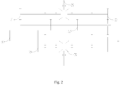
Fig. 2 is a schematic diagram showing the principle of connecting two incomplete gear sets in the cable transmission mechanism with the mold moving rotary winding wheel and the blank conveying rotary winding wheel. - In the above figures, the components indicated by the reference numerals are as follows: 1. A power source; 2. a cable transmission mechanism; 3. an oil tank; 4. a mold moving supporting plate; 5. a front drive piston; 6. an ejection plate; 7. an energy storage oil cylinder; 8. a male mold supporting plate; 9. a male mold; 10. a blank shuttle; 11. a feeding device; 12. a female mold; 13. a blank shuttle supporting frame; 14. a compression molding switch valve; 15. a pressure relief oil guiding plate; 16. a compression molding oil guiding plate; 17. a linkage bar supporting holder; 18. a return spring; 19. a three-bar linkage mechanism; 20. a second mold moving spring; 21. a pressure relief valve; 22. a linkage bar supporting holder; 23. a blank conveying cable holder; 24. a blank conveying cable; 25. a mold moving cable; 26. a compression molding oil cylinder; 27. an ejection rod; 28. a first mold moving spring; 29. a mold moving incomplete gear set; 30. a mold moving rotary winding wheel; 31. a blank conveying incomplete gear set; 32. a blank conveying rotary winding wheel; 33. a spur gear set; 34. a bottle cap product; and 35. a bevel gear set.
- The present invention will be further described in detail below with reference to the examples, but the embodiments of the present invention are not limited thereto.
- A device for batched compression molding of rubber and plastic products by means of multiple mold cavities of this example, as shown in
Fig. 1 , comprises a cable transmission mechanism, a three-bar linkage mechanism, a bottle cap mold, a blank shuttle and a male mold supporting plate. - As shown in
Fig. 2 , the cable transmission mechanism comprises two incomplete gear sets, a mold moving rotary winding wheel, a mold moving cable, a blank conveying rotary winding wheel and a blank conveying cable, and the two incomplete gear sets comprise a mold moving incomplete gear set and a blank conveying incomplete gear set. The bottle cap mold comprises a male mold and a female mold, a plurality of male molds being evenly distributed on the periphery of the male mold supporting plate, one female mold being arranged under each of the male molds, with one blank shuttle arranged between the male mold and the female mold of each pair. - The mold moving incomplete gear set and the mold moving rotary winding wheel are connected; the blank conveying incomplete gear set and the blank conveying rotary winding wheel are connected; one end of the mold moving cable is wound on the mold moving rotary winding wheel, and the other end of the mold moving cable is connected with the male mold supporting plate; one end of the blank conveying cable is wound on the blank conveying rotary winding wheel, and the other end of the blank conveying cable is fixedly connected to the blank conveying cable holder; a plurality of three-bar linkage mechanisms are distributed on the blank conveying cable holder, wherein one end of each of the three-bar linkage mechanisms is connected with the blank conveying cable holder, and the other end of each of the three-bar linkage mechanisms is correspondingly connected with one blank shuttle. Wherein the mold moving incomplete gear set drives the mold moving rotary winding wheel to rotate, so that the mold moving cable is unwound or wound, thereby driving the male mold to move up or down through the male mold supporting plate to realize mold opening or closing. In the process, the blank conveying incomplete gear set drives the blank conveying rotary winding wheel to rotate (the mold moving rotary winding wheel and the blank conveying rotary winding wheel alternately operate), so that the blank conveying cable is unwound or wound, thereby driving the blank conveying cable holder to move up or down and driving the blank shuttle through the three-bar linkage mechanism to enter into or exit from the lower part of the male mold. The blank in the blank shuttle is provided by a feeding device located therebelow.
- A blank-conveying cable-holder supporting column is arranged in the middle of the blank conveying cable holder, and provided with a blank shuttle supporting frame on the lower periphery, with each of the blank shuttles distributed on the blank shuttle supporting frame; the blank conveying cable holder, the blank-conveying cable-holder supporting column and the blank shuttle supporting frame form a blank conveying cable mechanism. Wherein the blank-conveying cable-holder supporting column is arranged mainly for providing more precise guidance and support for the up and down movement of the blank conveying cable holder, and also for providing guidance and support by using the blank shuttle supporting frame for each of the blank shuttles to enter into or exit from the bottle cap mold.
- A linkage bar supporting holder, provided inside with a return spring, is further arranged in the middle of the blank-conveying cable-holder supporting column, and respectively connected with each of the three-bar linkage mechanisms. The setting of the linkage bar supporting holder can make the operation of each of the three-bar linkage mechanisms more stable, so that the blank shuttle can be accurately positioned when feeding.
- An ejection plate is arranged in parallel above the male mold supporting plate, and a first mold moving spring is disposed between the ejection plate and the male mold supporting plate. The ejection plate is provided on the outer circumference with a plurality of ejection rods, each of which is correspondingly located on one side of one male mold. The ejection plate and the first mold moving spring are arranged to realize the spring energy storage while the mold is being opened, and meanwhile the ejection plate provides support for each of the ejection rods, so that the ejection rod can quickly eject the bottle cap product when the mold is opened.
- A mold moving supporting plate is arranged in parallel above the ejection plate, and a second mold moving spring is arranged between the mold moving supporting plate and the ejection plate. The male mold supporting plate is provided with a compression molding oil cylinder, whose piston passes through the ejection plate to be located in the second mold moving spring. The compression molding oil cylinder is provided at the bottom with a compression molding oil guiding plate and a compression molding switch valve, and a pressure relief oil guiding plate is arranged at the bottom of the compression molding oil guiding plate.
- In order to further realize the isostatic pressing energy storage while the mold is being opened, the mold moving supporting plate is also provided with an oil tank, and the male mold supporting plate is provided with an energy storage oil cylinder, with the front drive piston of the energy storage oil cylinder passing through the ejection plate to get connected with the oil tank. A pressure relief valve is provided on one side of the energy storage oil cylinder. The energy storage oil cylinder can also be externally connected to a pressurized positioning device through the pressure relief valve. The pressurized positioning device, which has the same specific structure as the existing one in the market, comprises a pressurized positioning bolt, a pressurized positioning spring and a pressurized positioning bolt reset disk, and can be used to control the pressure relief valve to be on/off to limit the front drive piston.
- A method for batched compression molding of rubber and plastic products by means of multiple mold cavities implemented by above device is as follows: According to the method, alternate operation of a blank shuttle and a male mold that is in a bottle cap mold is controlled by means of engagement of two incomplete gear sets; besides, in the engagement process of the two incomplete gear sets, mold opening motion, isostatic pressing energy storage and spring energy storage are implemented by means of the engagement characteristic of the incomplete gear sets, and fast mold closing and compression molding are implemented by means of the non-engagement characteristic, isostatic pressing energy storage and pressurization of the incomplete gear sets. A three-bar linkage mechanism is disposed between the incomplete gear set and the blank shuttle, and the incomplete gear set uses the three-bar linkage mechanism to control the blank shuttle to quickly and synchronously convey a blank to a master mold in the bottle cap mold. The blank shuttle and the male mold have the same motion period. The two incomplete gear sets are connected to the same power source through the bevel gear set on one side, and the spur gear set and the bevel gear set on the other side serve as a power transmission unit between the two incomplete gear sets.
- The above-mentioned method and device for batched compression molding of rubber and plastic products by means of multiple mold cavities has the following principle when used for production: When the mold moving incomplete gear set is engaged, the motor as the power source drives the mold moving rotary winding wheel to rotate, and the mold moving cable pulls the male mold supporting plate up to realize the mold opening and at the same time get the bottle cap products ejected. In the process, the first mold moving spring is compressed to store energy, and the energy storage oil cylinder also stores energy, with the stored energy used for pressurized compression molding and pressure retention during mold closing. When the mold opening is completed, the blank conveying incomplete gear set is disengaged, and the three-bar linkage mechanism is driven to expand by the blank conveying rotary winding wheel, the blank conveying cable and the blank conveying cable holder, thereby driving the blank shuttle to shuttle out of the bottle cap mold for cutting the blank. Then the blank is blown to the master mold by the gas through a gas conduit inside the blank shuttle, and next the blank shuttle remains stationary until the blank conveying incomplete gear set is re-engaged. When the incomplete gear set is re-engaged, the three-bar linkage mechanism retracts to drive the blank shuttle to shuttle into the bottle cap mold. At this time, the mold moving incomplete gear set is disengaged, the ejection plate and the male mold supporting plate are moved down respectively by the ejecting force of the first mold moving spring and the second mold moving spring to perform mold closing, and the pressure oil flows from the energy storage oil cylinder into the compression molding oil cylinder for pressurized compression molding and pressure retention until the mold moving incomplete gear set is re-engaged. In the above process, the blank shuttle and the male mold have the same motion period that is generally designed to be 2 s.
- The present invention can be better implemented as described above, and the above example is merely preferred one of the present invention and not intended to limit the scope of the present invention; that is, all equivalent changes and modifications made in accordance with the present invention are covered by the scope as claimed in the claims of the present invention.
Claims (10)
- A method for batched compression molding of rubber and plastic products by means of multiple mold cavities, characterized in that: according to the method, alternate operation of a blank shuttle and a male mold that is in a bottle cap mold is controlled by means of engagement of two incomplete gear sets; besides, in the engagement process of the two incomplete gear sets, mold opening motion, isostatic pressing energy storage and spring energy storage are implemented by means of the engagement characteristic of the incomplete gear sets, and fast mold closing and compression molding are implemented by means of the non-engagement characteristic, isostatic pressing energy storage and pressurization of the incomplete gear sets.
- The method for batched compression molding of rubber and plastic products by means of multiple mold cavities according to claim 1, characterized in that: a three-bar linkage mechanism is disposed between the incomplete gear set and the blank shuttle, and the incomplete gear set uses the three-bar linkage mechanism to control the blank shuttle to quickly and synchronously convey a blank to a master mold in the bottle cap mold.
- The method for batched compression molding of rubber and plastic products by means of multiple mold cavities according to claim 1, characterized in that: the blank shuttle and the male mold have the same motion period.
- The method for batched compression molding of rubber and plastic products by means of multiple mold cavities according to claim 1, characterized in that: the two incomplete gear sets are externally connected to the same power source.
- A device for batched compression molding of rubber and plastic products by means of multiple mold cavities, characterized in that: the device comprises a cable transmission mechanism, a three-bar linkage mechanism, a bottle cap mold, a blank shuttle and a male mold supporting plate;
the cable transmission mechanism comprises two incomplete gear sets, a mold moving rotary winding wheel, a mold moving cable, a blank conveying rotary winding wheel and a blank conveying cable, and the two incomplete gear sets comprise a mold moving incomplete gear set and a blank conveying incomplete gear set;
the bottle cap mold comprises a male mold and a female mold, a plurality of male molds being evenly distributed on the periphery of the male mold supporting plate, one female mold being arranged under each of the male molds, with one blank shuttle arranged between the male mold and the female mold of each pair;
the mold moving incomplete gear set and the mold moving rotary winding wheel are connected; the blank conveying incomplete gear set and the blank conveying rotary winding wheel are connected; one end of the mold moving cable is wound on the mold moving rotary winding wheel, and the other end of the mold moving cable is connected with the male mold supporting plate; one end of the blank conveying cable is wound on the blank conveying rotary winding wheel, and the other end of the blank conveying cable is fixedly connected to the blank conveying cable holder; a plurality of three-bar linkage mechanisms are distributed on the blank conveying cable holder, wherein one end of each of the three-bar linkage mechanisms is connected with the blank conveying cable holder, and the other end of each of the three-bar linkage mechanisms is correspondingly connected with one blank shuttle. - The device for batched compression molding of rubber and plastic products by means of multiple mold cavities according to claim 5, characterized in that: a blank-conveying cable-holder supporting column is arranged in the middle of the blank conveying cable holder, and provided with a blank shuttle supporting frame on the lower periphery, with each of the blank shuttles distributed on the blank shuttle supporting frame; the blank conveying cable holder, the blank-conveying cable-holder supporting column and the blank shuttle supporting frame form a blank conveying cable mechanism.
- The device for batched compression molding of rubber and plastic products by means of multiple mold cavities according to claim 6, characterized in that: a linkage bar supporting holder, provided inside with a return spring, is further arranged in the middle of the blank-conveying cable-holder supporting column, and respectively connected with each of the three-bar linkage mechanisms.
- The device for batched compression molding of rubber and plastic products by means of multiple mold cavities according to claim 5, characterized in that: an ejection plate is arranged in parallel above the male mold supporting plate, and a first mold moving spring is disposed between the ejection plate and the male mold supporting plate; the ejection plate is provided on the outer circumference with a plurality of ejection rods, each of which is correspondingly located on one side of one male mold.
- The device for batched compression molding of rubber and plastic products by means of multiple mold cavities according to claim 8, characterized in that: a mold moving supporting plate is arranged in parallel above the ejection plate, and a second mold moving spring is arranged between the mold moving supporting plate and the ejection plate; the male mold supporting plate is provided with a compression molding oil cylinder, whose piston passes through the ejection plate to be located in the second mold moving spring; the compression molding oil cylinder is provided at the bottom with a compression molding oil guiding plate and a compression molding switch valve, and a pressure relief oil guiding plate is arranged at the bottom of the compression molding oil guiding plate.
- The device for batched compression molding of rubber and plastic products by means of multiple mold cavities according to claim 9, characterized in that: the mold moving supporting plate is provided with an oil tank, and the male mold supporting plate is provided with an energy storage oil cylinder, with the front drive piston of the energy storage oil cylinder passing through the ejection plate to get connected with the oil tank; a pressure relief valve is provided on one side of the energy storage oil cylinder.
Applications Claiming Priority (2)
| Application Number | Priority Date | Filing Date | Title |
|---|---|---|---|
| CN201611035807.4A CN106393537B (en) | 2016-11-22 | 2016-11-22 | A kind of product of rubber and plastic batch compression molding method and device that multimode cavity is parallel |
| PCT/CN2017/093765 WO2018095062A1 (en) | 2016-11-22 | 2017-07-21 | Method and device for batched compression molding of rubber and plastic products by means of multiple mold cavities |
Publications (3)
| Publication Number | Publication Date |
|---|---|
| EP3488987A1 true EP3488987A1 (en) | 2019-05-29 |
| EP3488987A4 EP3488987A4 (en) | 2019-08-14 |
| EP3488987B1 EP3488987B1 (en) | 2021-01-13 |
Family
ID=58082354
Family Applications (1)
| Application Number | Title | Priority Date | Filing Date |
|---|---|---|---|
| EP17873442.2A Active EP3488987B1 (en) | 2016-11-22 | 2017-07-21 | Method and device for batched compression molding of rubber and plastic products by means of multiple mold cavities |
Country Status (14)
| Country | Link |
|---|---|
| US (1) | US11247370B2 (en) |
| EP (1) | EP3488987B1 (en) |
| JP (1) | JP6796706B2 (en) |
| KR (1) | KR20190013972A (en) |
| CN (1) | CN106393537B (en) |
| AU (1) | AU2017366138B2 (en) |
| BR (1) | BR112019003449A2 (en) |
| CA (1) | CA3025582C (en) |
| MX (1) | MX2019003331A (en) |
| MY (1) | MY196221A (en) |
| RU (1) | RU2722663C1 (en) |
| SG (1) | SG11201810651TA (en) |
| WO (1) | WO2018095062A1 (en) |
| ZA (1) | ZA201808236B (en) |
Families Citing this family (12)
| Publication number | Priority date | Publication date | Assignee | Title |
|---|---|---|---|---|
| CN106393537B (en) | 2016-11-22 | 2019-01-15 | 华南理工大学 | A kind of product of rubber and plastic batch compression molding method and device that multimode cavity is parallel |
| CN109366831B (en) * | 2018-10-30 | 2021-02-23 | 济南欧德复合材料有限公司 | Composite material processing equipment for aerospace field |
| CN109454798B (en) * | 2019-01-05 | 2024-04-02 | 广东星联精密机械有限公司 | Pressurizing mechanism for establishing compression molding movable mold plate mold locking force |
| CN110126323A (en) * | 2019-06-05 | 2019-08-16 | 无锡市荣允瓶盖有限公司 | A kind of plastic bottle closure production method of good airproof performance |
| CN111016042B (en) * | 2019-12-27 | 2020-10-30 | 深圳市鼎盛精密工业有限公司 | Integral type plastics compression moulding mould |
| CN112140288B (en) * | 2020-09-24 | 2021-07-30 | 湖南省新化县鑫星电子陶瓷有限责任公司 | High-reliability mechanical automatic ceramic plate dry pressing device |
| CN113352532B (en) * | 2021-04-28 | 2023-04-25 | 济南泉之韵家用电器有限公司 | Quick compression molding and effective demoulding device for air conditioner external unit mounting plate |
| CN114406632B (en) * | 2021-12-07 | 2023-03-28 | 天地人技术集团有限公司 | Dry filter composite set is used in air conditioner production |
| CN114274439B (en) * | 2022-03-07 | 2022-07-05 | 成都航利航空科技有限责任公司 | Rubber product three-dimensional layout production framework based on intelligent unit and production method |
| CN116690879B (en) * | 2023-07-27 | 2025-12-09 | 四川欣达复合材料有限公司 | Die machining equipment and process with limiting function |
| IT202300019509A1 (en) * | 2023-09-22 | 2025-03-22 | Italica S R L | PROCEDURE AND MOLD FOR THE PRODUCTION OF COMPOSITE MATERIAL OBJECTS |
| CN120962970B (en) * | 2025-10-17 | 2025-12-30 | 浙江世泰实业有限公司 | A molding die for automotive active hydraulic suspension bushings |
Family Cites Families (26)
| Publication number | Priority date | Publication date | Assignee | Title |
|---|---|---|---|---|
| US2476574A (en) * | 1945-01-08 | 1949-07-19 | Aluotto Antonio | Baling press |
| US3457694A (en) * | 1966-08-25 | 1969-07-29 | Hideo Tatibana | Method of and apparatus for fusion sealing the opening of flexible plastic bottle-like containers |
| SU407743A1 (en) * | 1970-08-06 | 1973-12-10 | DEVICE FOR WRINKING AND PRESSING PIPES FROM GLASS-PLASTIC | |
| US3724257A (en) * | 1971-09-17 | 1973-04-03 | Vandervell Products Ltd | Apparatus for manufacturing thin wall flexible bearing liners |
| US4104845A (en) * | 1974-05-21 | 1978-08-08 | B & H Manufacturing Company, Inc. | Method and apparatus for applying sleeves to necks of bottles and other containers |
| US4022052A (en) * | 1976-05-13 | 1977-05-10 | Hallenbeck Sales Co., Inc. | Stamping press with augmented power stroke |
| IT1238648B (en) * | 1990-04-13 | 1993-08-31 | Sacmi | DEVICE FOR RETENTION OF BOWLS OF CROWN CAPS. |
| JPH05154859A (en) | 1991-12-06 | 1993-06-22 | Japan Crown Cork Co Ltd | Synthetic resin material supply device and sealing liner forming system |
| EP1308263A3 (en) * | 1992-11-25 | 2003-05-21 | E. Khashoggi Industries, Llc | Highly inorganically filled compositions |
| JP2635935B2 (en) * | 1994-07-12 | 1997-07-30 | 清一郎 山上 | Mold opening and closing device for rubber molding press |
| JP2001179749A (en) * | 1999-12-27 | 2001-07-03 | Sato Tekkosho:Kk | Molding die clamping device |
| IT1321322B1 (en) * | 2000-05-05 | 2004-01-08 | Sacmi | CAROUSEL EQUIPMENT FOR THE MANUFACTURE, THROUGH THE OPENING MOLDING, OF PLASTIC CAPSULES |
| CN2495459Y (en) * | 2001-07-12 | 2002-06-19 | 王友钦 | Hand-operated moulding pressing apparatus |
| ITBO20010555A1 (en) * | 2001-09-14 | 2003-03-14 | Sacmi | EQUIPMENT FOR FORMING AND APPLICATION OF SEAL IN CAPSULES |
| ITRE20030001A1 (en) * | 2003-01-13 | 2004-07-14 | Sacmi | "FORMING MACHINE FOR DIFFERENT ITEMS, SUCH AS CAPSULES, BY COMPRESSION PRINTING |
| ITMO20030289A1 (en) * | 2003-10-23 | 2005-04-24 | Sacmi | EQUIPMENT, METHOD AND ARTICLE. |
| ITMO20040248A1 (en) * | 2004-09-24 | 2004-12-24 | Sacmi Cooperativa Meccanici Imola Scarl | OPERATING MACHINE EQUIPPED WITH A MULTIPLE OF APPARATUS ACTUATORS AND CONTROL SYSTEM. |
| US7628601B2 (en) * | 2007-07-30 | 2009-12-08 | Rexam Closure Systems Inc. | Machine for compression molding plastic articles |
| CN101985244B (en) * | 2010-10-31 | 2013-07-24 | 华南理工大学 | Electrical die opening and closing device for blow molding and realization method thereof |
| CN102862296B (en) * | 2012-08-08 | 2014-12-10 | 广州晶品包装机械有限公司 | Fully-automatic die pressing lid maker |
| CN102837412B (en) * | 2012-09-21 | 2014-07-09 | 台州市黄岩凯普机械有限公司 | Equipment for processing plastic bottle cap by extrusion compression molding |
| ITMO20130324A1 (en) * | 2013-11-29 | 2015-05-30 | Sacmi | FORMING APPARATUS |
| CN104002443B (en) * | 2014-05-15 | 2016-07-06 | 华南理工大学 | The servo-actuated liftout attachment of remote power stay-supported batch products and method |
| CN105326157B (en) * | 2015-10-13 | 2017-10-17 | 江苏火电电力设备制造有限公司 | A kind of device for reclaiming shoe tree |
| CN206264240U (en) * | 2016-11-22 | 2017-06-20 | 华南理工大学 | A kind of parallel product of rubber and plastic batch compression molding device of multimode cavity |
| CN106393537B (en) * | 2016-11-22 | 2019-01-15 | 华南理工大学 | A kind of product of rubber and plastic batch compression molding method and device that multimode cavity is parallel |
-
2016
- 2016-11-22 CN CN201611035807.4A patent/CN106393537B/en active Active
-
2017
- 2017-07-21 CA CA3025582A patent/CA3025582C/en active Active
- 2017-07-21 EP EP17873442.2A patent/EP3488987B1/en active Active
- 2017-07-21 MY MYPI2019001023A patent/MY196221A/en unknown
- 2017-07-21 KR KR1020187037940A patent/KR20190013972A/en not_active Ceased
- 2017-07-21 BR BR112019003449A patent/BR112019003449A2/en not_active IP Right Cessation
- 2017-07-21 SG SG11201810651TA patent/SG11201810651TA/en unknown
- 2017-07-21 RU RU2019101670A patent/RU2722663C1/en active
- 2017-07-21 JP JP2019503416A patent/JP6796706B2/en active Active
- 2017-07-21 US US16/339,796 patent/US11247370B2/en active Active
- 2017-07-21 MX MX2019003331A patent/MX2019003331A/en unknown
- 2017-07-21 WO PCT/CN2017/093765 patent/WO2018095062A1/en not_active Ceased
- 2017-07-21 AU AU2017366138A patent/AU2017366138B2/en active Active
-
2018
- 2018-12-06 ZA ZA2018/08236A patent/ZA201808236B/en unknown
Also Published As
| Publication number | Publication date |
|---|---|
| RU2722663C1 (en) | 2020-06-02 |
| MY196221A (en) | 2023-03-23 |
| EP3488987A4 (en) | 2019-08-14 |
| CN106393537B (en) | 2019-01-15 |
| AU2017366138B2 (en) | 2019-08-15 |
| CA3025582A1 (en) | 2018-05-31 |
| SG11201810651TA (en) | 2018-12-28 |
| EP3488987B1 (en) | 2021-01-13 |
| US20200039123A1 (en) | 2020-02-06 |
| JP6796706B2 (en) | 2020-12-09 |
| JP2019524493A (en) | 2019-09-05 |
| KR20190013972A (en) | 2019-02-11 |
| US11247370B2 (en) | 2022-02-15 |
| WO2018095062A1 (en) | 2018-05-31 |
| BR112019003449A2 (en) | 2019-07-02 |
| CA3025582C (en) | 2020-11-03 |
| ZA201808236B (en) | 2019-08-28 |
| CN106393537A (en) | 2017-02-15 |
| AU2017366138A1 (en) | 2019-01-17 |
| MX2019003331A (en) | 2019-06-03 |
Similar Documents
| Publication | Publication Date | Title |
|---|---|---|
| AU2017366138B2 (en) | Method and device for batched compression molding of rubber and plastic products by means of multiple mold cavities | |
| CN101620929B (en) | Magnetic ring automatic arrangement mechanism | |
| CN203764846U (en) | Hot forging mechanical arm and hot forging nut automatic forming device with same | |
| CN201092387Y (en) | Bag-in-bag full-automatic shaping packer | |
| CN203854173U (en) | Preform tail cutting machine | |
| CN203292211U (en) | Main machine for metal plastic extrusion molding | |
| CN203726766U (en) | Material cutting mechanism for bottle blank bagging machine/tail shearing machine | |
| CN206264240U (en) | A kind of parallel product of rubber and plastic batch compression molding device of multimode cavity | |
| HK40009202A (en) | Method and device for batched compression molding of rubber and plastic products by means of multiple mold cavities | |
| CN208616244U (en) | One kind cardboard automatic packing machine to be packaged | |
| HK40009202B (en) | Method and device for batched compression molding of rubber and plastic products by means of multiple mold cavities | |
| CN202864868U (en) | Capping machine | |
| CN203665811U (en) | Horizontal type angie type ZDZS injection-compression molding device | |
| CN206780888U (en) | Simplified Rotary core puller | |
| CN203449370U (en) | Ramming and stacking mechanism for forming machine | |
| CN201770044U (en) | Automatic coding cigarette carton storage device | |
| CN202491954U (en) | Carton overwrapping and shaping device | |
| CN213533942U (en) | Multiple feeding device for automatic hydraulic press for various powder materials | |
| CN211338758U (en) | Automatic production line from empty bottle feeding and filling to packaging | |
| CN201385406Y (en) | Dual-color injection mould with movable isolation sheet | |
| CN208291526U (en) | A kind of transparent membrane packaging machine | |
| CN202427916U (en) | Excess material ejection mechanism for fixed die | |
| CN203357830U (en) | Secondary ejection mechanism for plastic cement mould | |
| CN201751160U (en) | Plastic mold with sliding blocks driven by fixed mold push plate | |
| CN203381828U (en) | Automatic lifting bag library |
Legal Events
| Date | Code | Title | Description |
|---|---|---|---|
| STAA | Information on the status of an ep patent application or granted ep patent |
Free format text: STATUS: THE INTERNATIONAL PUBLICATION HAS BEEN MADE |
|
| PUAI | Public reference made under article 153(3) epc to a published international application that has entered the european phase |
Free format text: ORIGINAL CODE: 0009012 |
|
| STAA | Information on the status of an ep patent application or granted ep patent |
Free format text: STATUS: REQUEST FOR EXAMINATION WAS MADE |
|
| 17P | Request for examination filed |
Effective date: 20190225 |
|
| AK | Designated contracting states |
Kind code of ref document: A1 Designated state(s): AL AT BE BG CH CY CZ DE DK EE ES FI FR GB GR HR HU IE IS IT LI LT LU LV MC MK MT NL NO PL PT RO RS SE SI SK SM TR |
|
| AX | Request for extension of the european patent |
Extension state: BA ME |
|
| A4 | Supplementary search report drawn up and despatched |
Effective date: 20190715 |
|
| RIC1 | Information provided on ipc code assigned before grant |
Ipc: B29C 43/50 20060101ALI20190709BHEP Ipc: B30B 15/32 20060101ALI20190709BHEP Ipc: B29D 99/00 20100101ALI20190709BHEP Ipc: B29C 43/32 20060101AFI20190709BHEP Ipc: B30B 15/30 20060101ALI20190709BHEP Ipc: B29L 31/56 20060101ALN20190709BHEP Ipc: B30B 9/30 20060101ALI20190709BHEP Ipc: B29C 43/34 20060101ALI20190709BHEP Ipc: B30B 1/30 20060101ALI20190709BHEP |
|
| STAA | Information on the status of an ep patent application or granted ep patent |
Free format text: STATUS: EXAMINATION IS IN PROGRESS |
|
| DAV | Request for validation of the european patent (deleted) | ||
| DAX | Request for extension of the european patent (deleted) | ||
| 17Q | First examination report despatched |
Effective date: 20200224 |
|
| REG | Reference to a national code |
Ref country code: HK Ref legal event code: DE Ref document number: 40009202 Country of ref document: HK |
|
| REG | Reference to a national code |
Ref country code: DE Ref legal event code: R079 Ref document number: 602017031523 Country of ref document: DE Free format text: PREVIOUS MAIN CLASS: B29C0043460000 Ipc: B29C0043320000 |
|
| GRAP | Despatch of communication of intention to grant a patent |
Free format text: ORIGINAL CODE: EPIDOSNIGR1 |
|
| STAA | Information on the status of an ep patent application or granted ep patent |
Free format text: STATUS: GRANT OF PATENT IS INTENDED |
|
| RIC1 | Information provided on ipc code assigned before grant |
Ipc: B29D 99/00 20100101ALI20200721BHEP Ipc: B29C 43/50 20060101ALI20200721BHEP Ipc: B30B 15/32 20060101ALI20200721BHEP Ipc: B29C 43/32 20060101AFI20200721BHEP Ipc: B30B 1/02 20060101ALI20200721BHEP Ipc: B30B 1/30 20060101ALI20200721BHEP Ipc: B29L 31/56 20060101ALN20200721BHEP Ipc: B30B 9/30 20060101ALI20200721BHEP Ipc: B29C 43/34 20060101ALI20200721BHEP Ipc: B30B 15/30 20060101ALI20200721BHEP |
|
| INTG | Intention to grant announced |
Effective date: 20200818 |
|
| GRAS | Grant fee paid |
Free format text: ORIGINAL CODE: EPIDOSNIGR3 |
|
| GRAA | (expected) grant |
Free format text: ORIGINAL CODE: 0009210 |
|
| STAA | Information on the status of an ep patent application or granted ep patent |
Free format text: STATUS: THE PATENT HAS BEEN GRANTED |
|
| AK | Designated contracting states |
Kind code of ref document: B1 Designated state(s): AL AT BE BG CH CY CZ DE DK EE ES FI FR GB GR HR HU IE IS IT LI LT LU LV MC MK MT NL NO PL PT RO RS SE SI SK SM TR |
|
| REG | Reference to a national code |
Ref country code: GB Ref legal event code: FG4D |
|
| REG | Reference to a national code |
Ref country code: CH Ref legal event code: EP |
|
| REG | Reference to a national code |
Ref country code: IE Ref legal event code: FG4D |
|
| REG | Reference to a national code |
Ref country code: DE Ref legal event code: R096 Ref document number: 602017031523 Country of ref document: DE |
|
| REG | Reference to a national code |
Ref country code: AT Ref legal event code: REF Ref document number: 1354223 Country of ref document: AT Kind code of ref document: T Effective date: 20210215 |
|
| REG | Reference to a national code |
Ref country code: AT Ref legal event code: MK05 Ref document number: 1354223 Country of ref document: AT Kind code of ref document: T Effective date: 20210113 |
|
| REG | Reference to a national code |
Ref country code: NL Ref legal event code: MP Effective date: 20210113 |
|
| REG | Reference to a national code |
Ref country code: LT Ref legal event code: MG9D |
|
| PG25 | Lapsed in a contracting state [announced via postgrant information from national office to epo] |
Ref country code: LT Free format text: LAPSE BECAUSE OF FAILURE TO SUBMIT A TRANSLATION OF THE DESCRIPTION OR TO PAY THE FEE WITHIN THE PRESCRIBED TIME-LIMIT Effective date: 20210113 Ref country code: BG Free format text: LAPSE BECAUSE OF FAILURE TO SUBMIT A TRANSLATION OF THE DESCRIPTION OR TO PAY THE FEE WITHIN THE PRESCRIBED TIME-LIMIT Effective date: 20210413 Ref country code: PT Free format text: LAPSE BECAUSE OF FAILURE TO SUBMIT A TRANSLATION OF THE DESCRIPTION OR TO PAY THE FEE WITHIN THE PRESCRIBED TIME-LIMIT Effective date: 20210513 Ref country code: NO Free format text: LAPSE BECAUSE OF FAILURE TO SUBMIT A TRANSLATION OF THE DESCRIPTION OR TO PAY THE FEE WITHIN THE PRESCRIBED TIME-LIMIT Effective date: 20210413 Ref country code: GR Free format text: LAPSE BECAUSE OF FAILURE TO SUBMIT A TRANSLATION OF THE DESCRIPTION OR TO PAY THE FEE WITHIN THE PRESCRIBED TIME-LIMIT Effective date: 20210414 Ref country code: FI Free format text: LAPSE BECAUSE OF FAILURE TO SUBMIT A TRANSLATION OF THE DESCRIPTION OR TO PAY THE FEE WITHIN THE PRESCRIBED TIME-LIMIT Effective date: 20210113 Ref country code: HR Free format text: LAPSE BECAUSE OF FAILURE TO SUBMIT A TRANSLATION OF THE DESCRIPTION OR TO PAY THE FEE WITHIN THE PRESCRIBED TIME-LIMIT Effective date: 20210113 |
|
| PG25 | Lapsed in a contracting state [announced via postgrant information from national office to epo] |
Ref country code: SE Free format text: LAPSE BECAUSE OF FAILURE TO SUBMIT A TRANSLATION OF THE DESCRIPTION OR TO PAY THE FEE WITHIN THE PRESCRIBED TIME-LIMIT Effective date: 20210113 Ref country code: LV Free format text: LAPSE BECAUSE OF FAILURE TO SUBMIT A TRANSLATION OF THE DESCRIPTION OR TO PAY THE FEE WITHIN THE PRESCRIBED TIME-LIMIT Effective date: 20210113 Ref country code: RS Free format text: LAPSE BECAUSE OF FAILURE TO SUBMIT A TRANSLATION OF THE DESCRIPTION OR TO PAY THE FEE WITHIN THE PRESCRIBED TIME-LIMIT Effective date: 20210113 Ref country code: PL Free format text: LAPSE BECAUSE OF FAILURE TO SUBMIT A TRANSLATION OF THE DESCRIPTION OR TO PAY THE FEE WITHIN THE PRESCRIBED TIME-LIMIT Effective date: 20210113 Ref country code: AT Free format text: LAPSE BECAUSE OF FAILURE TO SUBMIT A TRANSLATION OF THE DESCRIPTION OR TO PAY THE FEE WITHIN THE PRESCRIBED TIME-LIMIT Effective date: 20210113 |
|
| PG25 | Lapsed in a contracting state [announced via postgrant information from national office to epo] |
Ref country code: IS Free format text: LAPSE BECAUSE OF FAILURE TO SUBMIT A TRANSLATION OF THE DESCRIPTION OR TO PAY THE FEE WITHIN THE PRESCRIBED TIME-LIMIT Effective date: 20210513 |
|
| REG | Reference to a national code |
Ref country code: DE Ref legal event code: R097 Ref document number: 602017031523 Country of ref document: DE |
|
| PG25 | Lapsed in a contracting state [announced via postgrant information from national office to epo] |
Ref country code: EE Free format text: LAPSE BECAUSE OF FAILURE TO SUBMIT A TRANSLATION OF THE DESCRIPTION OR TO PAY THE FEE WITHIN THE PRESCRIBED TIME-LIMIT Effective date: 20210113 Ref country code: CZ Free format text: LAPSE BECAUSE OF FAILURE TO SUBMIT A TRANSLATION OF THE DESCRIPTION OR TO PAY THE FEE WITHIN THE PRESCRIBED TIME-LIMIT Effective date: 20210113 Ref country code: SM Free format text: LAPSE BECAUSE OF FAILURE TO SUBMIT A TRANSLATION OF THE DESCRIPTION OR TO PAY THE FEE WITHIN THE PRESCRIBED TIME-LIMIT Effective date: 20210113 |
|
| PLBE | No opposition filed within time limit |
Free format text: ORIGINAL CODE: 0009261 |
|
| STAA | Information on the status of an ep patent application or granted ep patent |
Free format text: STATUS: NO OPPOSITION FILED WITHIN TIME LIMIT |
|
| PG25 | Lapsed in a contracting state [announced via postgrant information from national office to epo] |
Ref country code: DK Free format text: LAPSE BECAUSE OF FAILURE TO SUBMIT A TRANSLATION OF THE DESCRIPTION OR TO PAY THE FEE WITHIN THE PRESCRIBED TIME-LIMIT Effective date: 20210113 Ref country code: SK Free format text: LAPSE BECAUSE OF FAILURE TO SUBMIT A TRANSLATION OF THE DESCRIPTION OR TO PAY THE FEE WITHIN THE PRESCRIBED TIME-LIMIT Effective date: 20210113 Ref country code: RO Free format text: LAPSE BECAUSE OF FAILURE TO SUBMIT A TRANSLATION OF THE DESCRIPTION OR TO PAY THE FEE WITHIN THE PRESCRIBED TIME-LIMIT Effective date: 20210113 |
|
| 26N | No opposition filed |
Effective date: 20211014 |
|
| PG25 | Lapsed in a contracting state [announced via postgrant information from national office to epo] |
Ref country code: ES Free format text: LAPSE BECAUSE OF FAILURE TO SUBMIT A TRANSLATION OF THE DESCRIPTION OR TO PAY THE FEE WITHIN THE PRESCRIBED TIME-LIMIT Effective date: 20210113 Ref country code: AL Free format text: LAPSE BECAUSE OF FAILURE TO SUBMIT A TRANSLATION OF THE DESCRIPTION OR TO PAY THE FEE WITHIN THE PRESCRIBED TIME-LIMIT Effective date: 20210113 |
|
| PG25 | Lapsed in a contracting state [announced via postgrant information from national office to epo] |
Ref country code: SI Free format text: LAPSE BECAUSE OF FAILURE TO SUBMIT A TRANSLATION OF THE DESCRIPTION OR TO PAY THE FEE WITHIN THE PRESCRIBED TIME-LIMIT Effective date: 20210113 |
|
| REG | Reference to a national code |
Ref country code: CH Ref legal event code: PL |
|
| PG25 | Lapsed in a contracting state [announced via postgrant information from national office to epo] |
Ref country code: MC Free format text: LAPSE BECAUSE OF FAILURE TO SUBMIT A TRANSLATION OF THE DESCRIPTION OR TO PAY THE FEE WITHIN THE PRESCRIBED TIME-LIMIT Effective date: 20210113 |
|
| REG | Reference to a national code |
Ref country code: BE Ref legal event code: MM Effective date: 20210731 |
|
| PG25 | Lapsed in a contracting state [announced via postgrant information from national office to epo] |
Ref country code: LI Free format text: LAPSE BECAUSE OF NON-PAYMENT OF DUE FEES Effective date: 20210731 Ref country code: IT Free format text: LAPSE BECAUSE OF FAILURE TO SUBMIT A TRANSLATION OF THE DESCRIPTION OR TO PAY THE FEE WITHIN THE PRESCRIBED TIME-LIMIT Effective date: 20210113 Ref country code: CH Free format text: LAPSE BECAUSE OF NON-PAYMENT OF DUE FEES Effective date: 20210731 |
|
| PG25 | Lapsed in a contracting state [announced via postgrant information from national office to epo] |
Ref country code: IS Free format text: LAPSE BECAUSE OF FAILURE TO SUBMIT A TRANSLATION OF THE DESCRIPTION OR TO PAY THE FEE WITHIN THE PRESCRIBED TIME-LIMIT Effective date: 20210513 Ref country code: LU Free format text: LAPSE BECAUSE OF NON-PAYMENT OF DUE FEES Effective date: 20210721 |
|
| PG25 | Lapsed in a contracting state [announced via postgrant information from national office to epo] |
Ref country code: IE Free format text: LAPSE BECAUSE OF NON-PAYMENT OF DUE FEES Effective date: 20210721 Ref country code: BE Free format text: LAPSE BECAUSE OF NON-PAYMENT OF DUE FEES Effective date: 20210731 |
|
| PG25 | Lapsed in a contracting state [announced via postgrant information from national office to epo] |
Ref country code: NL Free format text: LAPSE BECAUSE OF NON-PAYMENT OF DUE FEES Effective date: 20210113 Ref country code: CY Free format text: LAPSE BECAUSE OF FAILURE TO SUBMIT A TRANSLATION OF THE DESCRIPTION OR TO PAY THE FEE WITHIN THE PRESCRIBED TIME-LIMIT Effective date: 20210113 |
|
| PG25 | Lapsed in a contracting state [announced via postgrant information from national office to epo] |
Ref country code: HU Free format text: LAPSE BECAUSE OF FAILURE TO SUBMIT A TRANSLATION OF THE DESCRIPTION OR TO PAY THE FEE WITHIN THE PRESCRIBED TIME-LIMIT; INVALID AB INITIO Effective date: 20170721 |
|
| PG25 | Lapsed in a contracting state [announced via postgrant information from national office to epo] |
Ref country code: MK Free format text: LAPSE BECAUSE OF FAILURE TO SUBMIT A TRANSLATION OF THE DESCRIPTION OR TO PAY THE FEE WITHIN THE PRESCRIBED TIME-LIMIT Effective date: 20210113 |
|
| PG25 | Lapsed in a contracting state [announced via postgrant information from national office to epo] |
Ref country code: TR Free format text: LAPSE BECAUSE OF FAILURE TO SUBMIT A TRANSLATION OF THE DESCRIPTION OR TO PAY THE FEE WITHIN THE PRESCRIBED TIME-LIMIT Effective date: 20210113 |
|
| PG25 | Lapsed in a contracting state [announced via postgrant information from national office to epo] |
Ref country code: MT Free format text: LAPSE BECAUSE OF FAILURE TO SUBMIT A TRANSLATION OF THE DESCRIPTION OR TO PAY THE FEE WITHIN THE PRESCRIBED TIME-LIMIT Effective date: 20210113 |
|
| PGFP | Annual fee paid to national office [announced via postgrant information from national office to epo] |
Ref country code: FR Payment date: 20250527 Year of fee payment: 9 |
|
| PGFP | Annual fee paid to national office [announced via postgrant information from national office to epo] |
Ref country code: DE Payment date: 20250722 Year of fee payment: 9 |
|
| PGFP | Annual fee paid to national office [announced via postgrant information from national office to epo] |
Ref country code: GB Payment date: 20250701 Year of fee payment: 9 |