EP3488965A1 - Centering device for bars - Google Patents
Centering device for bars Download PDFInfo
- Publication number
- EP3488965A1 EP3488965A1 EP18207453.4A EP18207453A EP3488965A1 EP 3488965 A1 EP3488965 A1 EP 3488965A1 EP 18207453 A EP18207453 A EP 18207453A EP 3488965 A1 EP3488965 A1 EP 3488965A1
- Authority
- EP
- European Patent Office
- Prior art keywords
- centering
- axis
- bar
- centering axis
- rolling members
- Prior art date
- Legal status (The legal status is an assumption and is not a legal conclusion. Google has not performed a legal analysis and makes no representation as to the accuracy of the status listed.)
- Granted
Links
- 238000005096 rolling process Methods 0.000 claims abstract description 53
- 230000000712 assembly Effects 0.000 claims abstract description 19
- 238000000429 assembly Methods 0.000 claims abstract description 19
- 230000008878 coupling Effects 0.000 claims description 10
- 238000010168 coupling process Methods 0.000 claims description 10
- 238000005859 coupling reaction Methods 0.000 claims description 10
- 238000006073 displacement reaction Methods 0.000 claims description 2
- 230000010355 oscillation Effects 0.000 abstract description 7
- 238000003754 machining Methods 0.000 description 3
- 238000002360 preparation method Methods 0.000 description 3
- 230000003213 activating effect Effects 0.000 description 1
- 239000012530 fluid Substances 0.000 description 1
- 230000002093 peripheral effect Effects 0.000 description 1
Images


Classifications
-
- B—PERFORMING OPERATIONS; TRANSPORTING
- B23—MACHINE TOOLS; METAL-WORKING NOT OTHERWISE PROVIDED FOR
- B23Q—DETAILS, COMPONENTS, OR ACCESSORIES FOR MACHINE TOOLS, e.g. ARRANGEMENTS FOR COPYING OR CONTROLLING; MACHINE TOOLS IN GENERAL CHARACTERISED BY THE CONSTRUCTION OF PARTICULAR DETAILS OR COMPONENTS; COMBINATIONS OR ASSOCIATIONS OF METAL-WORKING MACHINES, NOT DIRECTED TO A PARTICULAR RESULT
- B23Q1/00—Members which are comprised in the general build-up of a form of machine, particularly relatively large fixed members
- B23Q1/72—Auxiliary arrangements; Interconnections between auxiliary tables and movable machine elements
- B23Q1/76—Steadies; Rests
-
- B—PERFORMING OPERATIONS; TRANSPORTING
- B23—MACHINE TOOLS; METAL-WORKING NOT OTHERWISE PROVIDED FOR
- B23B—TURNING; BORING
- B23B13/00—Arrangements for automatically conveying or chucking or guiding stock
-
- B—PERFORMING OPERATIONS; TRANSPORTING
- B23—MACHINE TOOLS; METAL-WORKING NOT OTHERWISE PROVIDED FOR
- B23B—TURNING; BORING
- B23B13/00—Arrangements for automatically conveying or chucking or guiding stock
- B23B13/12—Accessories, e.g. stops, grippers
-
- B—PERFORMING OPERATIONS; TRANSPORTING
- B23—MACHINE TOOLS; METAL-WORKING NOT OTHERWISE PROVIDED FOR
- B23Q—DETAILS, COMPONENTS, OR ACCESSORIES FOR MACHINE TOOLS, e.g. ARRANGEMENTS FOR COPYING OR CONTROLLING; MACHINE TOOLS IN GENERAL CHARACTERISED BY THE CONSTRUCTION OF PARTICULAR DETAILS OR COMPONENTS; COMBINATIONS OR ASSOCIATIONS OF METAL-WORKING MACHINES, NOT DIRECTED TO A PARTICULAR RESULT
- B23Q3/00—Devices holding, supporting, or positioning work or tools, of a kind normally removable from the machine
- B23Q3/18—Devices holding, supporting, or positioning work or tools, of a kind normally removable from the machine for positioning only
- B23Q3/183—Centering devices
Definitions
- the invention relates to a centering device for bars, in particular for bars which are fed to a machine tool and which, during processing, are rotated about its longitudinal axis.
- the device in object can be usefully used for centering bars during the loading and/or unloading of the bars with respect to a lathe, for example a fixed head lathe.
- a centering device which can be arranged between a bar feeder and a machine tool (lathe) to keep the bar centered during processing between the feeder and the machine and limit the oscillation of the bar during the rotation of the same.
- FR 2319446 A1 discloses a centering device in which a guide assembly comprises three rolling members arranged around a centering axis with the possibility of assuming at least two configurations in which the rolling members are arranged at two different radial distances from the centering axis so as to rotatably support, in a selective way, two cylindrical bodies with different external diameters.
- An object of the invention is to improve devices of the prior art for centering bars fed to and/or discharged from a machine tool.
- An advantage is to provide a centering device which can be adapted simply and rapidly to the diameter change of the bars being processed.
- An advantage is to provide a centering device with high efficiency to keep the bar being machined centered between the bar feeder and the machine tool spindle and to reduce the oscillations of the rotating bar.
- An advantage is to allow automatic centering of a bar-shaped bar support (bar adapter) which internally contains a bar and inside which the bar can slide.
- An advantage is to simplify the operations of preparing the centering device with respect to the prior art.
- An advantage is to provide a centering device that is constructively simple and economical.
- An advantage is to provide a centering device which is versatile and adaptable to use with bars of different diameters.
- An advantage is to give rise to a centering device usable both for bars to be machined, by placing the device in an inlet zone of the machine tool included between a bar loading apparatus and the machine tool, and for already machined bars, placing the device in an exit area of the machine tool between the machine tool and a bar unloading apparatus.
- a centering device comprises at least two guide assemblies, axially spaced from each other along a centering axis, each of which in turn comprises at least three rolling members arranged around the centering axis to rotatably support a cylindrical body, each rolling member being positioned in such a way as to regulate its radial distance from the centering axis and allow supporting cylindrical bodies of different diameters.
- Each rolling member may, in particular, carry a pin which slides within a groove formed in an adjustment body which can rotate about the centering axis upon command of motor means for adjusting the distance of the rolling element from the centering axis.
- the centering device may be arranged between a bar feeder and a lathe, or between a lathe and a bar unloader, to keep a bar centered during processing and to limit the oscillation of the bar during its rotation.
- the reference numeral 1 designates as a whole a centering device which may be arranged, as in this example, between a bar feeder 2 and a machine tool 3 (in this case the machine tool 3 it is a lathe, in particular a fixed-head lathe).
- the centering device 1 may, in particular, serve to keep a bar centered, which is loaded into the machine tool 3 by the bar feeder 2 to perform a machining operation.
- the centering device 1 may serve, in particular, to contain the oscillation of the bar while the bar, during processing, is placed in rotation (about its longitudinal axis) by a spindle of the machine tool 3.
- the centering device 1 may comprise, in particular, at least two guide assemblies (in the specific example, two guide assemblies) arranged axially spaced from one another along a centering axis.
- the centering axis of the centering device 1 may be coaxial with a supply axis of the bar feeder 2 and with a spindle axis of the machine tool 3.
- Each guide assembly may comprise, in particular, at least three rolling members 4 (in the specific example, three rolling members) arranged around the centering axis at a given radial distance (in particular, the same radial distance for all rolling elements 4) from the centering axis.
- Each rolling member 4 may be able to rotate (in an idle manner) around its own axis of rotation, in particular (as in this example) a rotation axis parallel to the centering axis.
- Each rolling element 4 may comprise, as in this example, a wheel designed for rolling contact with a cylindrical body (e.g. a bar adapter or a bar).
- each guide assembly may be able to perform a regulation movement, coordinated between all the rolling members 4, to vary their radial distance from the common centering axis with the possibility of assuming two or more adjustment configurations according to the diameter of the bar and/or the hollow support (adapter) that contains the bar.
- the rolling members 4 may assume at least one first configuration (for example a configuration of maximum diameter, such as the specific configuration shown in Figures 2 , 4 , 6 ), in which the rolling members 4 are arranged at a first radial distance (a relatively great distance) from the centering axis to rotatably support a first cylindrical body (a bar adapter and/or a bar of relatively large outside diameter, for example 100 mm), coaxially with the aforesaid centering axis.
- a first radial distance a relatively great distance from the centering axis to rotatably support a first cylindrical body (a bar adapter and/or a bar of relatively large outside diameter, for example 100 mm)
- the rolling members 4 may assume at least one second configuration (for example a configuration of minimum diameter, such as the specific configuration shown in Figures 3 , 5 , 7 ), in which the rolling members 4 are arranged at a second radial distance from the centering axis (a relatively small distance) different (in particular lesser) than the aforementioned first radial distance, to rotatably support a second cylindrical body (a bar adapter and/or a bar of relatively small diameter, e.g. 8 mm), with a different external diameter (for example smaller) than the first cylindrical body, coaxially with the centering axis.
- a second cylindrical body a bar adapter and/or a bar of relatively small diameter, e.g. 8 mm
- the rolling members 4 may assume a multiplicity of configurations comprised between the first and the second configuration, according to the diameter of the bar to be machined.
- the two guide assemblies may be, as in this example, coaxial with each other.
- the two guide assemblies may, in particular, be arranged at a certain axial distance from each other along the centering axis so as to be able to rotatably support a cylindrical body in collaboration (in particular, a bar or a bar adapter) and to keep the cylindrical body on its axis, particularly along the aforesaid centering axis.
- the two guide assemblies may cooperate, in particular, to rotatably support and keep the first cylindrical body or, selectively, the second cylindrical body centered on its axis.
- the two guide assemblies may support and maintain on the axis any cylindrical body (bar or bar adapter) with an external diameter between a maximum value (for example 100 mm) and a minimum value (for example 8 mm).
- the two guide assemblies are substantially symmetrically arranged with respect to each other, according to a median plane of symmetry (vertical) perpendicular to the centering axis
- Each rolling member 4 may be supported, as in this example, by a slide 5 or carriage sliding on guide means 6 (integral with a frame 7 of the centering device 1).
- Each slide 5 may be sliding, in particular, with at least one sliding component in a radial direction with respect to the centering axis.
- Each slide 5 may be, as in this specific example, sliding with a linear sliding axis in a straight radial direction with respect to the centering axis.
- each guide assembly may be arranged, in particular, circumferentially about the centering axis, for example in a regular manner, that is to say at the same angular distance from each other.
- each guide assembly comprises three rolling members 4, the rolling elements are arranged angularly spaced 120° from one another.
- At least one guide assembly may comprise at least one adjustment body 8 which can rotate about the centering axis.
- the adjustment body 8 may be coupled to the rolling members 4 of the respective guide assembly by a mechanism configured in such a way that a rotation of the adjustment body 8 about the centering axis corresponds to a coordinated movement of the rolling members 4 between two different configurations with two respective different radial distances from the centering axis.
- the mechanism may comprise, as in this specific example, at least three couplings (one for each rolling member 4) of the pin-groove type in which each coupling connects the rotatable adjustment body 8 with a respective rolling member 4.
- Each coupling may comprise, in particular, a groove 9 formed on the adjustment body 8 and a pin 10 integral with a respective rolling members 4 and sliding inside the respective groove 9.
- Each coupling may comprise, in particular, a groove 9 in the shape of curve that progressively moves away from the centering axis. This groove 9 may comprise, as in this example, a spiral-shaped groove wound around the centering axis.
- Each of the two adjustment bodies 8 may comprise, in particular, a body with a circular peripheral edge, for example a circular disk, rotatably housed within a respective circular seat formed in the frame 7 of the centering device 1.
- Each circular seat may be made, in particular, in a plate-shaped portion of the frame 7.
- the centering device 1 may comprise, in particular, at least two hollow supports for bars (interchangeable adapters 11). Each hollow (cylindrical) support or adapter 11 may be selectively mountable in a coaxial position with the centering axis. Each adapter 11 may comprise, in particular, an outer cylindrical surface and an inner cylindrical sliding surface configured for an axial sliding of a cylindrical body (bar) having an external diameter equal to a diameter of the aforementioned internal cylindrical sliding surface. In Figures 4 and 6 an adapter 11 of a larger diameter is visible (for example for bars of 100 mm), while in Figures 5 and 7 an adapter 11 of a smaller diameter is visible (for example for bars of 8 mm).
- each bar adapter 11 may contain a bar and may, in particular, allow an axial sliding of the bar.
- the centering device 1 may comprise, in particular, connection means for mechanically connecting two respective portions of the adjustment bodies 8 of the two guide assemblies to each other.
- Such portions of the adjustment bodies 8 may be, as in the example, eccentric, i.e. distant from the centering axis.
- the connecting means may comprise, in particular, at least one cross member 12 which connects the aforementioned eccentric portions (away from the centering axis) with each other.
- the cross member 12 may be extended in length parallel to the centering axis.
- the connecting means may comprise at least one slot 13 within which the cross member 12 is sliding with a sliding axis.
- the connecting means comprises two slots 13 side by side, within which the cross member 12 runs.
- the axis of sliding of the cross member 12 (in the slot(s) 13) may be, as in this case, transverse to the centering axis.
- the centering device 1 may comprise, in particular, motor means 14 configured to drive the movement of the rolling members 4 and to adjust their radial distance from the centering axis.
- the centering device 1 may comprise motor means 14 connected to the aforesaid connecting means for driving a movement of the connection means and consequently a rotation of the two adjustment bodies 8 (one for each guide assembly).
- the aforesaid motor means 14 may comprise, in particular, a linear actuator, for example a linear actuator with a transverse (and non-coplanar) actuator axis with respect to the centering axis.
- the motor means 14 comprises, in this specific example, a fluid actuated linear actuator (a pneumatic cylinder), although it is possible to provide motor means of another type, for example an electric actuator.
- the sliding axis of the cross member 12 may be, as in this case, transverse to the aforesaid actuator axis.
- Each slot 13 may be connected to a movable element of the motor means 14 (linear actuator), whereby a (linear) movement of the movable element of the motor means 14 may cause a (simultaneous) rotation of both the adjustment bodies 8.
- the rotation of the adjustment bodies 8 may in turn cause a (radial) displacement of the slides 5 along the guide means 6 (sliding guides) and the consequent variation of the radial distance of the rolling members 4 (carried by the slides 5) with respect to the centering axis.
- the grooves 9 essentially have the function of cam profiles which guide the movement of the pins 10. It is possible, however, to provide for the use of a mechanism of another type to control the regulation movement of the rolling members 4.
- the device described above allows automatic centering and practical and immediate adjustment according to the diameter of the bar.
- the centering device 1 relies, in particular, on the use of adapters 11 which are selectively positioned inside the device itself.
- Each bar adapter may contain the bar to be worked inside.
- Each bar adapter 11 may be inserted, in particular, into a central hole formed on the adjustment body 8.
- an operator can provide, if necessary, to change the adapter 11. This operation of change of the adapter 11 could be, substantially, the only manual phase performed by the operator.
- the step following the change of the adapter 11 may very easily comprise, starting from an open configuration of the rolling members 4 (at a great radial distance from the centering axis to allow the advancement of the bar), a command for activating the motor means 14 (pneumatic cylinder), which automatically closes on the adapter 11 and performs the centering of the bar, so that the bar is aligned with the axis of the machine tool 3 (lathe) and of the bar feeder 2.
- the automatic centering step with adjustment of the diameter of the bar may provide, as seen, a rotation of the adjustment bodies 8 (in the form of flat bodies or disks) driven by the motor means 14.
- This rotation involves closing the guide assemblies (including rolling members 4) in contact around the adapter of the bar.
- the guide assemblies substantially perform the function of rolling support means which allow the rotation of the bar around its own longitudinal axis (aligned with the centering axis) and which also act for radial locking of the adapter and/or of the bar in at least three radial zones angularly spaced from one another.
- the rolling members 4 configured for the rolling contact with the adapter are supported by elements (slides 5 or carriages) movable, in particular on sliding guides, to allow an adjustment movement when it is necessary to machine bars of different diameters.
- the centering device 1 allows a simple and rapid preparation for changing the diameter of the bar.
- the times for changing the adapter 11 are relatively small and the operations to be performed are remarkably practical and immediate for the operator to perform.
- the centering device 1 may be suitable for bars with diameters between 8 and 100 millimeters and with lengths between 200 and 1500 millimeters. It is however possible to use it for bars with larger and/or smaller diameters and longer and/or shorter lengths.
Landscapes
- Engineering & Computer Science (AREA)
- Mechanical Engineering (AREA)
- Turning (AREA)
Abstract
Description
- The invention relates to a centering device for bars, in particular for bars which are fed to a machine tool and which, during processing, are rotated about its longitudinal axis.
- Specifically, but not exclusively, the device in object can be usefully used for centering bars during the loading and/or unloading of the bars with respect to a lathe, for example a fixed head lathe.
- In particular, reference is made to a centering device which can be arranged between a bar feeder and a machine tool (lathe) to keep the bar centered during processing between the feeder and the machine and limit the oscillation of the bar during the rotation of the same.
- It is known to load a bar being processed on a lathe by means of a bar feeder. One of the problems of the prior art arises from the need to work bars of very different lengths from each other and from the constructive constraint determined by the various lengths of the spindles of the lathes. In fact, for very long bars being processed it is necessary to place the bar feeder at a certain distance from the lathe to recover the distance in the spindle necessary for machining. In this way, however, a gap is created, sometimes of considerable length, between the feeder and the lathe. It is known to fill this gap with a centering device which is positioned between the feeder and the lathe to facilitate centering of the bar and to reduce its oscillation.
-
FR 2319446 A1 - An object of the invention is to improve devices of the prior art for centering bars fed to and/or discharged from a machine tool.
- An advantage is to provide a centering device which can be adapted simply and rapidly to the diameter change of the bars being processed.
- An advantage is to provide a centering device with high efficiency to keep the bar being machined centered between the bar feeder and the machine tool spindle and to reduce the oscillations of the rotating bar.
- An advantage is to allow automatic centering of a bar-shaped bar support (bar adapter) which internally contains a bar and inside which the bar can slide.
- An advantage is to simplify the operations of preparing the centering device with respect to the prior art.
- An advantage is to provide a centering device that is constructively simple and economical.
- An advantage is to provide a centering device which is versatile and adaptable to use with bars of different diameters.
- An advantage is to give rise to a centering device usable both for bars to be machined, by placing the device in an inlet zone of the machine tool included between a bar loading apparatus and the machine tool, and for already machined bars, placing the device in an exit area of the machine tool between the machine tool and a bar unloading apparatus.
- Such objects and advantages and others are achieved by a centering device according to one or more of the claims set forth below.
- In one example, a centering device comprises at least two guide assemblies, axially spaced from each other along a centering axis, each of which in turn comprises at least three rolling members arranged around the centering axis to rotatably support a cylindrical body, each rolling member being positioned in such a way as to regulate its radial distance from the centering axis and allow supporting cylindrical bodies of different diameters. Each rolling member may, in particular, carry a pin which slides within a groove formed in an adjustment body which can rotate about the centering axis upon command of motor means for adjusting the distance of the rolling element from the centering axis. The centering device may be arranged between a bar feeder and a lathe, or between a lathe and a bar unloader, to keep a bar centered during processing and to limit the oscillation of the bar during its rotation.
- The invention can be better understood and implemented with reference to the attached drawings which illustrate a non-limiting example of implementation thereof:
-
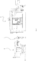
Figure 1 is a vertical elevational view of an example of a centering device made according to the invention and arranged between a bar feeder and a machine tool for machining the bars; -
Figure 2 is a vertical elevation view of the centering device ofFigure 1 with the device in a first configuration suitable for centering bars with a relatively large diameter; -
Figure 3 is the view ofFigure 2 with the device in a second configuration suitable for centering bars with a reduced diameter; -
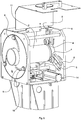
Figure 4 is a perspective view of the device in the first configuration ofFigure 2 with an open door to better show some internal parts; -
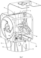
Figure 5 is the perspective view ofFigure 4 with the device in the second configuration ofFigure 3 ; -
Figure 6 shows an enlarged detail ofFigure 4 ; -
Figure 7 shows an enlarged detail ofFigure 5 . - Referring to the aforementioned figures, the
reference numeral 1 designates as a whole a centering device which may be arranged, as in this example, between abar feeder 2 and a machine tool 3 (in this case themachine tool 3 it is a lathe, in particular a fixed-head lathe). Thecentering device 1 may, in particular, serve to keep a bar centered, which is loaded into themachine tool 3 by thebar feeder 2 to perform a machining operation. Thecentering device 1 may serve, in particular, to contain the oscillation of the bar while the bar, during processing, is placed in rotation (about its longitudinal axis) by a spindle of themachine tool 3. - The
centering device 1 may comprise, in particular, at least two guide assemblies (in the specific example, two guide assemblies) arranged axially spaced from one another along a centering axis. The centering axis of thecentering device 1 may be coaxial with a supply axis of thebar feeder 2 and with a spindle axis of themachine tool 3. - Each guide assembly may comprise, in particular, at least three rolling members 4 (in the specific example, three rolling members) arranged around the centering axis at a given radial distance (in particular, the same radial distance for all rolling elements 4) from the centering axis.
- Each
rolling member 4 may be able to rotate (in an idle manner) around its own axis of rotation, in particular (as in this example) a rotation axis parallel to the centering axis. Eachrolling element 4 may comprise, as in this example, a wheel designed for rolling contact with a cylindrical body (e.g. a bar adapter or a bar). - The
rolling members 4 of each guide assembly may be able to perform a regulation movement, coordinated between all therolling members 4, to vary their radial distance from the common centering axis with the possibility of assuming two or more adjustment configurations according to the diameter of the bar and/or the hollow support (adapter) that contains the bar. - In particular, the
rolling members 4 may assume at least one first configuration (for example a configuration of maximum diameter, such as the specific configuration shown inFigures 2 ,4 ,6 ), in which therolling members 4 are arranged at a first radial distance (a relatively great distance) from the centering axis to rotatably support a first cylindrical body (a bar adapter and/or a bar of relatively large outside diameter, for example 100 mm), coaxially with the aforesaid centering axis. - In particular, the
rolling members 4 may assume at least one second configuration (for example a configuration of minimum diameter, such as the specific configuration shown inFigures 3 ,5 ,7 ), in which therolling members 4 are arranged at a second radial distance from the centering axis (a relatively small distance) different (in particular lesser) than the aforementioned first radial distance, to rotatably support a second cylindrical body (a bar adapter and/or a bar of relatively small diameter, e.g. 8 mm), with a different external diameter (for example smaller) than the first cylindrical body, coaxially with the centering axis. - In particular, the
rolling members 4 may assume a multiplicity of configurations comprised between the first and the second configuration, according to the diameter of the bar to be machined. - The two guide assemblies may be, as in this example, coaxial with each other. The two guide assemblies may, in particular, be arranged at a certain axial distance from each other along the centering axis so as to be able to rotatably support a cylindrical body in collaboration (in particular, a bar or a bar adapter) and to keep the cylindrical body on its axis, particularly along the aforesaid centering axis. The two guide assemblies may cooperate, in particular, to rotatably support and keep the first cylindrical body or, selectively, the second cylindrical body centered on its axis. In particular, the two guide assemblies may support and maintain on the axis any cylindrical body (bar or bar adapter) with an external diameter between a maximum value (for example 100 mm) and a minimum value (for example 8 mm). In the specific example described herein, the two guide assemblies are substantially symmetrically arranged with respect to each other, according to a median plane of symmetry (vertical) perpendicular to the centering axis
- (horizontal). It is noted that in the perspective views, according to
Figures 4 to 7 , a guide assembly is visible from the outside while the other guide assembly is visible from the inside. - Each
rolling member 4 may be supported, as in this example, by aslide 5 or carriage sliding on guide means 6 (integral with aframe 7 of the centering device 1). Eachslide 5 may be sliding, in particular, with at least one sliding component in a radial direction with respect to the centering axis. Eachslide 5 may be, as in this specific example, sliding with a linear sliding axis in a straight radial direction with respect to the centering axis. - The various rolling
members 4 of each guide assembly may be arranged, in particular, circumferentially about the centering axis, for example in a regular manner, that is to say at the same angular distance from each other. In the specific case, in which each guide assembly comprises threerolling members 4, the rolling elements are arranged angularly spaced 120° from one another. - At least one guide assembly (in the specific case, each of the two guide assemblies) may comprise at least one
adjustment body 8 which can rotate about the centering axis. Theadjustment body 8 may be coupled to therolling members 4 of the respective guide assembly by a mechanism configured in such a way that a rotation of theadjustment body 8 about the centering axis corresponds to a coordinated movement of therolling members 4 between two different configurations with two respective different radial distances from the centering axis. - The mechanism may comprise, as in this specific example, at least three couplings (one for each rolling member 4) of the pin-groove type in which each coupling connects the
rotatable adjustment body 8 with a respectiverolling member 4. Each coupling may comprise, in particular, agroove 9 formed on theadjustment body 8 and apin 10 integral with a respective rollingmembers 4 and sliding inside therespective groove 9. Each coupling may comprise, in particular, agroove 9 in the shape of curve that progressively moves away from the centering axis. Thisgroove 9 may comprise, as in this example, a spiral-shaped groove wound around the centering axis. - Each of the two adjustment bodies 8 (one for each guide assembly) may comprise, in particular, a body with a circular peripheral edge, for example a circular disk, rotatably housed within a respective circular seat formed in the
frame 7 of the centeringdevice 1. Each circular seat may be made, in particular, in a plate-shaped portion of theframe 7. - The centering
device 1 may comprise, in particular, at least two hollow supports for bars (interchangeable adapters 11). Each hollow (cylindrical) support oradapter 11 may be selectively mountable in a coaxial position with the centering axis. Eachadapter 11 may comprise, in particular, an outer cylindrical surface and an inner cylindrical sliding surface configured for an axial sliding of a cylindrical body (bar) having an external diameter equal to a diameter of the aforementioned internal cylindrical sliding surface. InFigures 4 and6 anadapter 11 of a larger diameter is visible (for example for bars of 100 mm), while inFigures 5 and7 anadapter 11 of a smaller diameter is visible (for example for bars of 8 mm). It may be provided that, during the preparation of the centeringdevice 1, an operator coaxially inserts theadapter 11 of an appropriate diameter according to the diameter of the bar to be machined. Eachbar adapter 11 may contain a bar and may, in particular, allow an axial sliding of the bar. - The centering
device 1 may comprise, in particular, connection means for mechanically connecting two respective portions of theadjustment bodies 8 of the two guide assemblies to each other. Such portions of theadjustment bodies 8 may be, as in the example, eccentric, i.e. distant from the centering axis. - The connecting means may comprise, in particular, at least one
cross member 12 which connects the aforementioned eccentric portions (away from the centering axis) with each other. Thecross member 12 may be extended in length parallel to the centering axis. The connecting means may comprise at least oneslot 13 within which thecross member 12 is sliding with a sliding axis. In the specific case, the connecting means comprises twoslots 13 side by side, within which thecross member 12 runs. The axis of sliding of the cross member 12 (in the slot(s) 13) may be, as in this case, transverse to the centering axis. - The centering
device 1 may comprise, in particular, motor means 14 configured to drive the movement of the rollingmembers 4 and to adjust their radial distance from the centering axis. In particular, the centeringdevice 1 may comprise motor means 14 connected to the aforesaid connecting means for driving a movement of the connection means and consequently a rotation of the two adjustment bodies 8 (one for each guide assembly). - The aforesaid motor means 14 may comprise, in particular, a linear actuator, for example a linear actuator with a transverse (and non-coplanar) actuator axis with respect to the centering axis. The motor means 14 comprises, in this specific example, a fluid actuated linear actuator (a pneumatic cylinder), although it is possible to provide motor means of another type, for example an electric actuator.
- The sliding axis of the cross member 12 (in the slot(s) 13) may be, as in this case, transverse to the aforesaid actuator axis.
- Each
slot 13 may be connected to a movable element of the motor means 14 (linear actuator), whereby a (linear) movement of the movable element of the motor means 14 may cause a (simultaneous) rotation of both theadjustment bodies 8. The rotation of theadjustment bodies 8 may in turn cause a (radial) displacement of theslides 5 along the guide means 6 (sliding guides) and the consequent variation of the radial distance of the rolling members 4 (carried by the slides 5) with respect to the centering axis. This occurs in this specific example due to the coupling between thegrooves 9 on theadjustment bodies 8 and thepins 10 on the rollingmembers 4. Thegrooves 9 essentially have the function of cam profiles which guide the movement of thepins 10. It is possible, however, to provide for the use of a mechanism of another type to control the regulation movement of the rollingmembers 4. - The device described above allows automatic centering and practical and immediate adjustment according to the diameter of the bar. The centering
device 1 relies, in particular, on the use ofadapters 11 which are selectively positioned inside the device itself. Each bar adapter may contain the bar to be worked inside. Eachbar adapter 11 may be inserted, in particular, into a central hole formed on theadjustment body 8. During the preparation of the centering device before processing, an operator can provide, if necessary, to change theadapter 11. This operation of change of theadapter 11 could be, substantially, the only manual phase performed by the operator. - Once the bar is fed towards the
machine tool 3 by thebar feeder 2, before starting the processing, the step following the change of theadapter 11 may very easily comprise, starting from an open configuration of the rolling members 4 (at a great radial distance from the centering axis to allow the advancement of the bar), a command for activating the motor means 14 (pneumatic cylinder), which automatically closes on theadapter 11 and performs the centering of the bar, so that the bar is aligned with the axis of the machine tool 3 (lathe) and of thebar feeder 2. It is therefore possible to move to the processing step, in which themachine tool 3 makes the bar rotate around its longitudinal axis, while the centeringdevice 1 rotatably supports the bar, by virtue of the rolling coupling between the cylindrical body (adapter 11 or directly the bar) and the rollingmembers 4, containing and limiting the oscillations due to the rotation. - The automatic centering step with adjustment of the diameter of the bar may provide, as seen, a rotation of the adjustment bodies 8 (in the form of flat bodies or disks) driven by the motor means 14. This rotation involves closing the guide assemblies (including rolling members 4) in contact around the adapter of the bar. The guide assemblies substantially perform the function of rolling support means which allow the rotation of the bar around its own longitudinal axis (aligned with the centering axis) and which also act for radial locking of the adapter and/or of the bar in at least three radial zones angularly spaced from one another.
- In this specific case, the rolling
members 4 configured for the rolling contact with the adapter are supported by elements (slides 5 or carriages) movable, in particular on sliding guides, to allow an adjustment movement when it is necessary to machine bars of different diameters. - The centering
device 1 allows a simple and rapid preparation for changing the diameter of the bar. In particular, the times for changing theadapter 11 are relatively small and the operations to be performed are remarkably practical and immediate for the operator to perform. - In the specific example, the centering
device 1 may be suitable for bars with diameters between 8 and 100 millimeters and with lengths between 200 and 1500 millimeters. It is however possible to use it for bars with larger and/or smaller diameters and longer and/or shorter lengths.
Claims (15)
- A centering device (1) comprising at least two guide assemblies each comprising at least three rolling members (4) arranged around a centering axis at a radial distance from said centering axis, said at least three rolling members (4) of each guide assembly being capable of performing a coordinated movement to vary said radial distance with the possibility of assuming at least one first configuration, wherein said rolling members (4) are arranged at a first radial distance from said centering axis to support a first cylindrical body rotatably and coaxially with said centering axis, and at least one second configuration, wherein said rolling members (4) are arranged at a second radial distance from said centering axis other than said first radial distance to support a second cylindrical body, with an external diameter other than the first cylindrical body, rotatably and coaxially with said centering axis, said at least two guide assemblies being coaxial with each other and arranged at an axial distance from each other along said centering axis to be able to rotatably support in collaboration selectively, the first cylindrical body or the second cylindrical body, at least one of said guide assemblies comprising an adjustment body (8) which can rotate about said centering axis, said adjustment body (8) being coupled to said at least three rolling members (4) by means of a mechanism such that a rotation of said adjustment body (8) causes a displacement of said rolling members (4) between said first and second configurations, said centering device comprising connecting means for mechanically connecting two respective portions of the adjustment bodies (8) of two guide assemblies, said portions being distant from said centering axis, said centering device comprising motor means (14) connected to said connecting means to actuate a movement of said connecting means and consequently a rotation of the adjustment bodies (8) of said guide assemblies.
- A device as claimed in claim 1, comprising at least one slider (5) supporting a respective rolling member (4) for each of said rolling members (4) and sliding with at least one sliding component in a radial direction with respect to said centering axis.
- A device as claimed in claim 2, wherein each slider (5) is slidable with a respective linear sliding axis having a radial direction with respect to said centering axis.
- A device as claimed in any one of the preceding claims, wherein, for each of said at least two guide assemblies, said at least three rolling members (4) are arranged circumferentially around said centering axis with a regular arrangement at the same angular distance one from the other.
- A device as claimed in any one of the preceding claims, wherein said mechanism comprises at least three couplings of pin-groove type in which each coupling connects said adjustment body (8) to a respective rolling member (4).
- A device as claimed in claim 5, wherein each of said couplings comprises a groove (9) formed on said adjustment body (8) and a pin (10) which is secured to a respective rolling member (4) and which is slidable within said groove (9).
- A device as claimed in claim 5 or 6, wherein each of said couplings comprises a curved groove (9) which progressively extends away from said centering axis.
- A device as claimed in claim 7, wherein said groove is a spiral groove (9) wound around said centering axis.
- A device as claimed in any one of the preceding claims, wherein said adjustment body (8) comprises a circular disk rotatably housed within a circular seat formed in a frame (7) of said device.
- A device as claimed in any one of the preceding claims, wherein said motor means (14) comprises a linear actuator with an actuator axis transverse to said centering axis.
- A device as claimed in any one of the preceding claims, wherein said connecting means comprises at least one cross member (12) connecting said portions of the adjustment bodies (8) distant from said centering axis, said cross member (12) extending in length parallel to said centering axis.
- A device as claimed in claims 11 and 10, wherein said connecting means comprises at least one slot (13) within which said cross member (12) is slidable with a sliding axis that is transverse to both said centering axis and said actuator axis, said slot (13) being connected to said actuator whereby a movement of said actuator causes rotation of said adjustment bodies (8).
- A device as claimed in any one of the preceding claims, comprising at least two hollow supports (11) each of which can be selectively mounted on said centering device in a coaxial position with said centering axis,
- A device as claimed in claim 13, wherein each hollow support (11) comprises an inner cylindrical sliding surface configured for an axial sliding of a cylindrical body having an outer diameter substantially equal to an inner diameter of said inner cylindrical sliding surface.
- A combination of a centering device (1) as claimed in any one of the preceding claims with a bar feeder (2) suitable for feeding bars to a machine tool (3) and/or a bar unloader suitable for unloading bars from a machine tool (3), wherein said centering device (1) and said bar feeder (2) and/or said bar unloader include bar alignment axes which can be aligned one to the other.
Applications Claiming Priority (1)
| Application Number | Priority Date | Filing Date | Title |
|---|---|---|---|
| IT201700134468 | 2017-11-23 |
Publications (2)
| Publication Number | Publication Date |
|---|---|
| EP3488965A1 true EP3488965A1 (en) | 2019-05-29 |
| EP3488965B1 EP3488965B1 (en) | 2022-04-20 |
Family
ID=61527401
Family Applications (1)
| Application Number | Title | Priority Date | Filing Date |
|---|---|---|---|
| EP18207453.4A Active EP3488965B1 (en) | 2017-11-23 | 2018-11-21 | Centering device for bars |
Country Status (1)
| Country | Link |
|---|---|
| EP (1) | EP3488965B1 (en) |
Cited By (3)
| Publication number | Priority date | Publication date | Assignee | Title |
|---|---|---|---|---|
| CN110524373A (en) * | 2019-09-05 | 2019-12-03 | 江苏托普车轮有限公司 | A kind of fixed device of adjustable tyre production |
| CN114007807A (en) * | 2019-06-04 | 2022-02-01 | 库奇乔瓦尼公司 | Bar centering device for bar feeder |
| IT202200007292A1 (en) | 2022-04-12 | 2023-10-12 | Top Automazioni S R L | Bar loader for lathes |
Citations (2)
| Publication number | Priority date | Publication date | Assignee | Title |
|---|---|---|---|---|
| FR2319446A1 (en) * | 1975-07-26 | 1977-02-25 | Lohner Alfred | PNEUMATIC STEM FEEDING DEVICE FOR ROD MACHINING LATHES |
| DE4122948A1 (en) * | 1991-07-11 | 1993-01-14 | Kieserling & Albrecht | Guide system for rods in paring or shelling machine using guide rollers - has spring loaded rollers arranged radially around machine centre, and unit for measuring position of roller holder relative to slider to match dia. of rod being paired |
-
2018
- 2018-11-21 EP EP18207453.4A patent/EP3488965B1/en active Active
Patent Citations (2)
| Publication number | Priority date | Publication date | Assignee | Title |
|---|---|---|---|---|
| FR2319446A1 (en) * | 1975-07-26 | 1977-02-25 | Lohner Alfred | PNEUMATIC STEM FEEDING DEVICE FOR ROD MACHINING LATHES |
| DE4122948A1 (en) * | 1991-07-11 | 1993-01-14 | Kieserling & Albrecht | Guide system for rods in paring or shelling machine using guide rollers - has spring loaded rollers arranged radially around machine centre, and unit for measuring position of roller holder relative to slider to match dia. of rod being paired |
Cited By (6)
| Publication number | Priority date | Publication date | Assignee | Title |
|---|---|---|---|---|
| CN114007807A (en) * | 2019-06-04 | 2022-02-01 | 库奇乔瓦尼公司 | Bar centering device for bar feeder |
| CN114007807B (en) * | 2019-06-04 | 2023-07-21 | 库奇乔瓦尼公司 | Bar centering device for bar feeder |
| CN110524373A (en) * | 2019-09-05 | 2019-12-03 | 江苏托普车轮有限公司 | A kind of fixed device of adjustable tyre production |
| CN110524373B (en) * | 2019-09-05 | 2021-02-05 | 江苏托普车轮有限公司 | Adjustable tire processing fixing device |
| IT202200007292A1 (en) | 2022-04-12 | 2023-10-12 | Top Automazioni S R L | Bar loader for lathes |
| EP4260968A1 (en) | 2022-04-12 | 2023-10-18 | Top Automazioni S.R.L. | Bar loader for lathes |
Also Published As
| Publication number | Publication date |
|---|---|
| EP3488965B1 (en) | 2022-04-20 |
Similar Documents
| Publication | Publication Date | Title |
|---|---|---|
| EP3488965B1 (en) | Centering device for bars | |
| US6434993B1 (en) | Bending machine for bending threadlike material such as tubes, rods profiles or metal wire | |
| US8404997B2 (en) | Machine arrangement for machining bar-like workpieces having a device for workpiece support | |
| US9022837B2 (en) | Honing machine for inner honing and outer honing | |
| US20160271702A1 (en) | Portable pipe lathe and method | |
| US10427260B2 (en) | Machine tool | |
| EP2974815B1 (en) | Power transmitting device for transmitting external force into rotating body, and orbital pipe cutting device and hydraulic chucking device able to freely control cutting tool movement inside rotating body by using the power transmitting device | |
| EP3423222B1 (en) | Radial centering device for bar loaders in automatic lathes | |
| JP2017513728A (en) | Orbital cutting device capable of freely and selectively controlling a plurality of cutting tools in a rotating body using a rotation speed ratio | |
| US10967436B2 (en) | Universal rotating chuck apparatus | |
| WO2017149449A1 (en) | Jaw-type centering device for bar loaders in automatic lathes | |
| EP3319746B1 (en) | Pipe end machining device | |
| EP3456444B1 (en) | Apparatus for feeding bars | |
| JP4377449B1 (en) | Sheet glass processing equipment | |
| CN102728959A (en) | Holding and drive device for a tube support element | |
| JP2014501180A (en) | Improved grinding machine and grinding method | |
| JP2014504216A (en) | Method for positioning a working cylinder in a grinding machine and grinding machine implementing the method | |
| US4130033A (en) | Multiple spindle automatic screw machine | |
| CN106041217B (en) | Piston ring chamfer machine | |
| US20210276106A1 (en) | Lathe | |
| RU2686426C1 (en) | Composite for cutting of long-length workpiece | |
| US9908179B2 (en) | Balancing device for a bar loading magazine | |
| JP2018516771A (en) | Lathe including guide bush | |
| CN106660149A (en) | Machine for machining workpieces, corresponding arrangement and method for machining workpieces | |
| JP6871031B2 (en) | Worm processing equipment and worm processing method |
Legal Events
| Date | Code | Title | Description |
|---|---|---|---|
| PUAI | Public reference made under article 153(3) epc to a published international application that has entered the european phase |
Free format text: ORIGINAL CODE: 0009012 |
|
| STAA | Information on the status of an ep patent application or granted ep patent |
Free format text: STATUS: THE APPLICATION HAS BEEN PUBLISHED |
|
| AK | Designated contracting states |
Kind code of ref document: A1 Designated state(s): AL AT BE BG CH CY CZ DE DK EE ES FI FR GB GR HR HU IE IS IT LI LT LU LV MC MK MT NL NO PL PT RO RS SE SI SK SM TR |
|
| AX | Request for extension of the european patent |
Extension state: BA ME |
|
| STAA | Information on the status of an ep patent application or granted ep patent |
Free format text: STATUS: REQUEST FOR EXAMINATION WAS MADE |
|
| 17P | Request for examination filed |
Effective date: 20191129 |
|
| RBV | Designated contracting states (corrected) |
Designated state(s): AL AT BE BG CH CY CZ DE DK EE ES FI FR GB GR HR HU IE IS IT LI LT LU LV MC MK MT NL NO PL PT RO RS SE SI SK SM TR |
|
| GRAP | Despatch of communication of intention to grant a patent |
Free format text: ORIGINAL CODE: EPIDOSNIGR1 |
|
| STAA | Information on the status of an ep patent application or granted ep patent |
Free format text: STATUS: GRANT OF PATENT IS INTENDED |
|
| INTG | Intention to grant announced |
Effective date: 20211112 |
|
| GRAS | Grant fee paid |
Free format text: ORIGINAL CODE: EPIDOSNIGR3 |
|
| GRAA | (expected) grant |
Free format text: ORIGINAL CODE: 0009210 |
|
| STAA | Information on the status of an ep patent application or granted ep patent |
Free format text: STATUS: THE PATENT HAS BEEN GRANTED |
|
| AK | Designated contracting states |
Kind code of ref document: B1 Designated state(s): AL AT BE BG CH CY CZ DE DK EE ES FI FR GB GR HR HU IE IS IT LI LT LU LV MC MK MT NL NO PL PT RO RS SE SI SK SM TR |
|
| REG | Reference to a national code |
Ref country code: GB Ref legal event code: FG4D |
|
| REG | Reference to a national code |
Ref country code: CH Ref legal event code: EP |
|
| REG | Reference to a national code |
Ref country code: DE Ref legal event code: R096 Ref document number: 602018034078 Country of ref document: DE |
|
| REG | Reference to a national code |
Ref country code: IE Ref legal event code: FG4D |
|
| REG | Reference to a national code |
Ref country code: AT Ref legal event code: REF Ref document number: 1484795 Country of ref document: AT Kind code of ref document: T Effective date: 20220515 |
|
| REG | Reference to a national code |
Ref country code: LT Ref legal event code: MG9D |
|
| REG | Reference to a national code |
Ref country code: NL Ref legal event code: MP Effective date: 20220420 |
|
| REG | Reference to a national code |
Ref country code: AT Ref legal event code: MK05 Ref document number: 1484795 Country of ref document: AT Kind code of ref document: T Effective date: 20220420 |
|
| PG25 | Lapsed in a contracting state [announced via postgrant information from national office to epo] |
Ref country code: NL Free format text: LAPSE BECAUSE OF FAILURE TO SUBMIT A TRANSLATION OF THE DESCRIPTION OR TO PAY THE FEE WITHIN THE PRESCRIBED TIME-LIMIT Effective date: 20220420 |
|
| PG25 | Lapsed in a contracting state [announced via postgrant information from national office to epo] |
Ref country code: SE Free format text: LAPSE BECAUSE OF FAILURE TO SUBMIT A TRANSLATION OF THE DESCRIPTION OR TO PAY THE FEE WITHIN THE PRESCRIBED TIME-LIMIT Effective date: 20220420 Ref country code: PT Free format text: LAPSE BECAUSE OF FAILURE TO SUBMIT A TRANSLATION OF THE DESCRIPTION OR TO PAY THE FEE WITHIN THE PRESCRIBED TIME-LIMIT Effective date: 20220822 Ref country code: NO Free format text: LAPSE BECAUSE OF FAILURE TO SUBMIT A TRANSLATION OF THE DESCRIPTION OR TO PAY THE FEE WITHIN THE PRESCRIBED TIME-LIMIT Effective date: 20220720 Ref country code: LT Free format text: LAPSE BECAUSE OF FAILURE TO SUBMIT A TRANSLATION OF THE DESCRIPTION OR TO PAY THE FEE WITHIN THE PRESCRIBED TIME-LIMIT Effective date: 20220420 Ref country code: HR Free format text: LAPSE BECAUSE OF FAILURE TO SUBMIT A TRANSLATION OF THE DESCRIPTION OR TO PAY THE FEE WITHIN THE PRESCRIBED TIME-LIMIT Effective date: 20220420 Ref country code: GR Free format text: LAPSE BECAUSE OF FAILURE TO SUBMIT A TRANSLATION OF THE DESCRIPTION OR TO PAY THE FEE WITHIN THE PRESCRIBED TIME-LIMIT Effective date: 20220721 Ref country code: FI Free format text: LAPSE BECAUSE OF FAILURE TO SUBMIT A TRANSLATION OF THE DESCRIPTION OR TO PAY THE FEE WITHIN THE PRESCRIBED TIME-LIMIT Effective date: 20220420 Ref country code: ES Free format text: LAPSE BECAUSE OF FAILURE TO SUBMIT A TRANSLATION OF THE DESCRIPTION OR TO PAY THE FEE WITHIN THE PRESCRIBED TIME-LIMIT Effective date: 20220420 Ref country code: BG Free format text: LAPSE BECAUSE OF FAILURE TO SUBMIT A TRANSLATION OF THE DESCRIPTION OR TO PAY THE FEE WITHIN THE PRESCRIBED TIME-LIMIT Effective date: 20220720 Ref country code: AT Free format text: LAPSE BECAUSE OF FAILURE TO SUBMIT A TRANSLATION OF THE DESCRIPTION OR TO PAY THE FEE WITHIN THE PRESCRIBED TIME-LIMIT Effective date: 20220420 |
|
| PG25 | Lapsed in a contracting state [announced via postgrant information from national office to epo] |
Ref country code: RS Free format text: LAPSE BECAUSE OF FAILURE TO SUBMIT A TRANSLATION OF THE DESCRIPTION OR TO PAY THE FEE WITHIN THE PRESCRIBED TIME-LIMIT Effective date: 20220420 Ref country code: PL Free format text: LAPSE BECAUSE OF FAILURE TO SUBMIT A TRANSLATION OF THE DESCRIPTION OR TO PAY THE FEE WITHIN THE PRESCRIBED TIME-LIMIT Effective date: 20220420 Ref country code: LV Free format text: LAPSE BECAUSE OF FAILURE TO SUBMIT A TRANSLATION OF THE DESCRIPTION OR TO PAY THE FEE WITHIN THE PRESCRIBED TIME-LIMIT Effective date: 20220420 Ref country code: IS Free format text: LAPSE BECAUSE OF FAILURE TO SUBMIT A TRANSLATION OF THE DESCRIPTION OR TO PAY THE FEE WITHIN THE PRESCRIBED TIME-LIMIT Effective date: 20220820 |
|
| REG | Reference to a national code |
Ref country code: DE Ref legal event code: R097 Ref document number: 602018034078 Country of ref document: DE |
|
| PG25 | Lapsed in a contracting state [announced via postgrant information from national office to epo] |
Ref country code: SM Free format text: LAPSE BECAUSE OF FAILURE TO SUBMIT A TRANSLATION OF THE DESCRIPTION OR TO PAY THE FEE WITHIN THE PRESCRIBED TIME-LIMIT Effective date: 20220420 Ref country code: SK Free format text: LAPSE BECAUSE OF FAILURE TO SUBMIT A TRANSLATION OF THE DESCRIPTION OR TO PAY THE FEE WITHIN THE PRESCRIBED TIME-LIMIT Effective date: 20220420 Ref country code: RO Free format text: LAPSE BECAUSE OF FAILURE TO SUBMIT A TRANSLATION OF THE DESCRIPTION OR TO PAY THE FEE WITHIN THE PRESCRIBED TIME-LIMIT Effective date: 20220420 Ref country code: EE Free format text: LAPSE BECAUSE OF FAILURE TO SUBMIT A TRANSLATION OF THE DESCRIPTION OR TO PAY THE FEE WITHIN THE PRESCRIBED TIME-LIMIT Effective date: 20220420 Ref country code: DK Free format text: LAPSE BECAUSE OF FAILURE TO SUBMIT A TRANSLATION OF THE DESCRIPTION OR TO PAY THE FEE WITHIN THE PRESCRIBED TIME-LIMIT Effective date: 20220420 Ref country code: CZ Free format text: LAPSE BECAUSE OF FAILURE TO SUBMIT A TRANSLATION OF THE DESCRIPTION OR TO PAY THE FEE WITHIN THE PRESCRIBED TIME-LIMIT Effective date: 20220420 |
|
| PLBE | No opposition filed within time limit |
Free format text: ORIGINAL CODE: 0009261 |
|
| STAA | Information on the status of an ep patent application or granted ep patent |
Free format text: STATUS: NO OPPOSITION FILED WITHIN TIME LIMIT |
|
| 26N | No opposition filed |
Effective date: 20230123 |
|
| PG25 | Lapsed in a contracting state [announced via postgrant information from national office to epo] |
Ref country code: AL Free format text: LAPSE BECAUSE OF FAILURE TO SUBMIT A TRANSLATION OF THE DESCRIPTION OR TO PAY THE FEE WITHIN THE PRESCRIBED TIME-LIMIT Effective date: 20220420 |
|
| PG25 | Lapsed in a contracting state [announced via postgrant information from national office to epo] |
Ref country code: SI Free format text: LAPSE BECAUSE OF FAILURE TO SUBMIT A TRANSLATION OF THE DESCRIPTION OR TO PAY THE FEE WITHIN THE PRESCRIBED TIME-LIMIT Effective date: 20220420 |
|
| REG | Reference to a national code |
Ref country code: DE Ref legal event code: R119 Ref document number: 602018034078 Country of ref document: DE |
|
| PG25 | Lapsed in a contracting state [announced via postgrant information from national office to epo] |
Ref country code: MC Free format text: LAPSE BECAUSE OF FAILURE TO SUBMIT A TRANSLATION OF THE DESCRIPTION OR TO PAY THE FEE WITHIN THE PRESCRIBED TIME-LIMIT Effective date: 20220420 |
|
| REG | Reference to a national code |
Ref country code: CH Ref legal event code: PL |
|
| GBPC | Gb: european patent ceased through non-payment of renewal fee |
Effective date: 20221121 |
|
| REG | Reference to a national code |
Ref country code: BE Ref legal event code: MM Effective date: 20221130 |
|
| PG25 | Lapsed in a contracting state [announced via postgrant information from national office to epo] |
Ref country code: LI Free format text: LAPSE BECAUSE OF NON-PAYMENT OF DUE FEES Effective date: 20221130 Ref country code: CH Free format text: LAPSE BECAUSE OF NON-PAYMENT OF DUE FEES Effective date: 20221130 |
|
| PG25 | Lapsed in a contracting state [announced via postgrant information from national office to epo] |
Ref country code: LU Free format text: LAPSE BECAUSE OF NON-PAYMENT OF DUE FEES Effective date: 20221121 |
|
| PG25 | Lapsed in a contracting state [announced via postgrant information from national office to epo] |
Ref country code: IE Free format text: LAPSE BECAUSE OF NON-PAYMENT OF DUE FEES Effective date: 20221121 Ref country code: GB Free format text: LAPSE BECAUSE OF NON-PAYMENT OF DUE FEES Effective date: 20221121 Ref country code: DE Free format text: LAPSE BECAUSE OF NON-PAYMENT OF DUE FEES Effective date: 20230601 |
|
| PG25 | Lapsed in a contracting state [announced via postgrant information from national office to epo] |
Ref country code: FR Free format text: LAPSE BECAUSE OF NON-PAYMENT OF DUE FEES Effective date: 20221130 Ref country code: BE Free format text: LAPSE BECAUSE OF NON-PAYMENT OF DUE FEES Effective date: 20221130 |
|
| PG25 | Lapsed in a contracting state [announced via postgrant information from national office to epo] |
Ref country code: IT Free format text: LAPSE BECAUSE OF FAILURE TO SUBMIT A TRANSLATION OF THE DESCRIPTION OR TO PAY THE FEE WITHIN THE PRESCRIBED TIME-LIMIT Effective date: 20220420 |
|
| PG25 | Lapsed in a contracting state [announced via postgrant information from national office to epo] |
Ref country code: HU Free format text: LAPSE BECAUSE OF FAILURE TO SUBMIT A TRANSLATION OF THE DESCRIPTION OR TO PAY THE FEE WITHIN THE PRESCRIBED TIME-LIMIT; INVALID AB INITIO Effective date: 20181121 |
|
| PG25 | Lapsed in a contracting state [announced via postgrant information from national office to epo] |
Ref country code: CY Free format text: LAPSE BECAUSE OF FAILURE TO SUBMIT A TRANSLATION OF THE DESCRIPTION OR TO PAY THE FEE WITHIN THE PRESCRIBED TIME-LIMIT Effective date: 20220420 |