EP3488867A1 - Antitumor aqueous solution manufacturing device - Google Patents
Antitumor aqueous solution manufacturing device Download PDFInfo
- Publication number
- EP3488867A1 EP3488867A1 EP16909489.3A EP16909489A EP3488867A1 EP 3488867 A1 EP3488867 A1 EP 3488867A1 EP 16909489 A EP16909489 A EP 16909489A EP 3488867 A1 EP3488867 A1 EP 3488867A1
- Authority
- EP
- European Patent Office
- Prior art keywords
- aqueous solution
- antitumor
- hydrogen peroxide
- raw material
- plasma
- Prior art date
- Legal status (The legal status is an assumption and is not a legal conclusion. Google has not performed a legal analysis and makes no representation as to the accuracy of the status listed.)
- Granted
Links
Images




Classifications
-
- B—PERFORMING OPERATIONS; TRANSPORTING
- B01—PHYSICAL OR CHEMICAL PROCESSES OR APPARATUS IN GENERAL
- B01J—CHEMICAL OR PHYSICAL PROCESSES, e.g. CATALYSIS OR COLLOID CHEMISTRY; THEIR RELEVANT APPARATUS
- B01J12/00—Chemical processes in general for reacting gaseous media with gaseous media; Apparatus specially adapted therefor
- B01J12/002—Chemical processes in general for reacting gaseous media with gaseous media; Apparatus specially adapted therefor carried out in the plasma state
-
- A—HUMAN NECESSITIES
- A61—MEDICAL OR VETERINARY SCIENCE; HYGIENE
- A61K—PREPARATIONS FOR MEDICAL, DENTAL OR TOILETRY PURPOSES
- A61K33/00—Medicinal preparations containing inorganic active ingredients
-
- H—ELECTRICITY
- H05—ELECTRIC TECHNIQUES NOT OTHERWISE PROVIDED FOR
- H05H—PLASMA TECHNIQUE; PRODUCTION OF ACCELERATED ELECTRICALLY-CHARGED PARTICLES OR OF NEUTRONS; PRODUCTION OR ACCELERATION OF NEUTRAL MOLECULAR OR ATOMIC BEAMS
- H05H1/00—Generating plasma; Handling plasma
- H05H1/24—Generating plasma
- H05H1/48—Generating plasma using an arc
-
- A—HUMAN NECESSITIES
- A61—MEDICAL OR VETERINARY SCIENCE; HYGIENE
- A61P—SPECIFIC THERAPEUTIC ACTIVITY OF CHEMICAL COMPOUNDS OR MEDICINAL PREPARATIONS
- A61P35/00—Antineoplastic agents
-
- B—PERFORMING OPERATIONS; TRANSPORTING
- B01—PHYSICAL OR CHEMICAL PROCESSES OR APPARATUS IN GENERAL
- B01J—CHEMICAL OR PHYSICAL PROCESSES, e.g. CATALYSIS OR COLLOID CHEMISTRY; THEIR RELEVANT APPARATUS
- B01J19/00—Chemical, physical or physico-chemical processes in general; Their relevant apparatus
- B01J19/08—Processes employing the direct application of electric or wave energy, or particle radiation; Apparatus therefor
- B01J19/087—Processes employing the direct application of electric or wave energy, or particle radiation; Apparatus therefor employing electric or magnetic energy
- B01J19/088—Processes employing the direct application of electric or wave energy, or particle radiation; Apparatus therefor employing electric or magnetic energy giving rise to electric discharges
-
- B—PERFORMING OPERATIONS; TRANSPORTING
- B01—PHYSICAL OR CHEMICAL PROCESSES OR APPARATUS IN GENERAL
- B01J—CHEMICAL OR PHYSICAL PROCESSES, e.g. CATALYSIS OR COLLOID CHEMISTRY; THEIR RELEVANT APPARATUS
- B01J2219/00—Chemical, physical or physico-chemical processes in general; Their relevant apparatus
- B01J2219/08—Processes employing the direct application of electric or wave energy, or particle radiation; Apparatus therefor
- B01J2219/0803—Processes employing the direct application of electric or wave energy, or particle radiation; Apparatus therefor employing electric or magnetic energy
- B01J2219/0805—Processes employing the direct application of electric or wave energy, or particle radiation; Apparatus therefor employing electric or magnetic energy giving rise to electric discharges
- B01J2219/0807—Processes employing the direct application of electric or wave energy, or particle radiation; Apparatus therefor employing electric or magnetic energy giving rise to electric discharges involving electrodes
- B01J2219/0809—Processes employing the direct application of electric or wave energy, or particle radiation; Apparatus therefor employing electric or magnetic energy giving rise to electric discharges involving electrodes employing two or more electrodes
-
- B—PERFORMING OPERATIONS; TRANSPORTING
- B01—PHYSICAL OR CHEMICAL PROCESSES OR APPARATUS IN GENERAL
- B01J—CHEMICAL OR PHYSICAL PROCESSES, e.g. CATALYSIS OR COLLOID CHEMISTRY; THEIR RELEVANT APPARATUS
- B01J2219/00—Chemical, physical or physico-chemical processes in general; Their relevant apparatus
- B01J2219/08—Processes employing the direct application of electric or wave energy, or particle radiation; Apparatus therefor
- B01J2219/0873—Materials to be treated
- B01J2219/0877—Liquid
-
- B—PERFORMING OPERATIONS; TRANSPORTING
- B01—PHYSICAL OR CHEMICAL PROCESSES OR APPARATUS IN GENERAL
- B01J—CHEMICAL OR PHYSICAL PROCESSES, e.g. CATALYSIS OR COLLOID CHEMISTRY; THEIR RELEVANT APPARATUS
- B01J2219/00—Chemical, physical or physico-chemical processes in general; Their relevant apparatus
- B01J2219/08—Processes employing the direct application of electric or wave energy, or particle radiation; Apparatus therefor
- B01J2219/0894—Processes carried out in the presence of a plasma
Definitions
- the present invention relates to an antitumor aqueous solution manufacturing device suitable for manufacturing an antitumor aqueous solution capable of killing tumor cells.
- Plasma which uses an effect of excited electrons, has been applied in various ways to fields of electricity, chemistry, materials, and medical care.
- a technology has been reported that, as application of plasma to medical care, a solution manufactured through plasma irradiation has an effect of killing a tumor (PTL 1).
- an aqueous solution having antitumor properties (hereinafter, referred to as "antitumor aqueous solution") that is generated through plasma irradiation varies in accordance with conditions such as a plasma irradiation time, and appropriate plasma irradiation conditions depend on the type of tumor.
- the invention is made in light of the situations, and a problem to be addressed is to provide an antitumor aqueous solution manufacturing device capable of manufacturing an antitumor aqueous solution having an appropriate antitumor effect.
- An antitumor aqueous solution manufacturing device of the invention that addresses the above-described problem is a device configured to manufacture an antitumor aqueous solution having an antitumor effect, the device including a holding portion configured to hold a raw material solution in which a raw material of the antitumor aqueous solution is dissolved; a plasma generating device configured to generate plasma to be radiated on the raw material solution in the holding portion; a hydrogen peroxide detection sensor configured to measure a hydrogen peroxide concentration in the raw material solution in the holding portion; and a control device configured to control the plasma generating device, the control device controlling the plasma generating device such that the hydrogen peroxide concentration measured by the hydrogen peroxide detection sensor falls within a predetermined range.
- an active component for an antitumor effect provided by an antitumor aqueous solution has not been adequately revealed, research findings tell that the degree of antitumor effect correlates with the hydrogen peroxide concentration.
- an antitumor aqueous solution that provides an appropriate effect depending on the type of tumor can be manufactured.
- desirable hydrogen peroxide concentrations can be preparatorily obtained depending on the type of tumor.
- PTL 2 discloses a water quality control device that decomposes organic substances in water to be processed by using hydrogen peroxide.
- the device disclosed in PTL 2 has a technology that controls electric power to be supplied to plasma electrodes, which are used for plasma irradiation, based on the hydrogen peroxide concentration in the water to be processed after plasma irradiation and that controls the distance between the plasma electrodes such that the irradiation can be continued under certain conditions even when a plasma generating device changes with time (for example, a change in the distance between the plasma electrodes due to wear of the plasma electrodes).
- the technology controls the output and the distance between the plasma electrodes in accordance with a change with time of the plasma electrodes to make the effect through plasma irradiation constant; however, the invention of this application is a technology different from the technology of PTL 2 in that conditions such as a plasma irradiation time is changed to make the effect of an antitumor aqueous solution to be generated constant.
- the manufacturing device capable of manufacturing an antitumor aqueous solution having an appropriate active component concentration depending on the tumor to which the antitumor aqueous solution is applied can be provided.
- An antitumor aqueous solution manufacturing device of the invention is described below in detail with reference to the drawings for example.
- An antitumor aqueous solution manufacturing device of this embodiment manufactures an antitumor aqueous solution by irradiating a raw material solution with plasma and thereby generating an antitumor component in the raw material solution.
- the antitumor aqueous solution manufacturing device of this embodiment is implemented by atmospheric-pressure plasma irradiation device 10 described below that performs plasma irradiation under the atmospheric pressure.
- Plasma irradiation is performed while the hydrogen peroxide concentration in the raw material solution is measured, and plasma irradiation is ended when the measured concentration has fallen in a predetermined concentration range. Because the hydrogen peroxide concentration correlates with the plasma irradiation conditions, controlling the hydrogen peroxide concentration provides an antitumor aqueous solution appropriately irradiated with plasma.
- the predetermined concentration range has appropriate values that vary in accordance with, for example, the type of tumor to which the antitumor aqueous solution is applied.
- the raw material solution during plasma irradiation may be left in a stationary state or in a circulation state. When plasma irradiation is performed, the raw material solution may be irradiated with plasma from above the solution surface.
- the manufactured antitumor aqueous solution can affect a tumor existing in a living body by being directly administered to the living body.
- the administration of the antitumor aqueous solution to the living body can employ a method of bringing the antitumor aqueous solution into contact with the tumor in a state exposed by a surgical treatment. For example, when a tumor was attempted to be removed but was not completely removed by a surgical treatment, the remaining tumor can be killed by the contact between the antitumor aqueous solution and the tumor through washing or the like during the surgical treatment.
- the raw material solution is an aqueous solution.
- the raw material solution is desirably an aqueous solution prepared by adding a solute containing at least one component selected from disodium hydrogen phosphate (Na 2 HPO 4 ), sodium hydrogen carbonate (NaHCO 3 ), L-glutamine, L-histidine, and L-tyrosine disodium (L-tyrosine ⁇ 2Na) to water.
- the raw material solution using the aqueous solution is irradiated with plasma and thus a highly effective antitumor aqueous solution with can be obtained.
- the raw material solution is desirably a living body fluid, or a culture solution for living body cells.
- Fig. 1 illustrates atmospheric-pressure plasma irradiation device 10 of an embodiment of the invention.
- Atmospheric-pressure plasma irradiation device 10 irradiates a culture solution serving as a raw material solution with plasma under the atmospheric pressure.
- the culture solution is held in petri dish 110 in a stationary state.
- Atmospheric-pressure plasma irradiation device 10 includes plasma generating device 20, cover housing 22, opening and closing mechanism 24, stage 26 serving as a holding portion that holds the raw material solution in petri dish 110, lifting and lowering device 28, cooling device (see Fig. 9 ) 30, purge gas supply mechanism (see Fig. 5 ) 32, oxygen concentration detection mechanism 34, hydrogen peroxide concentration detection mechanism (see Fig. 10 ) 35, exhaust mechanism 36, and control device (see Fig. 10 ) 38.
- a width direction of atmospheric-pressure plasma irradiation device 10 is referred to as X direction
- a depth direction of atmospheric-pressure plasma irradiation device 10 is referred to as Y direction
- a direction perpendicular to the X and Y directions, that is, an up-down direction, is referred to as Z direction.
- plasma generating device 20 includes cover 50, upper block 52, lower block 54, one pair of electrodes 56, and nozzle block 58.
- Cover 50 substantially has a lidded rectangular tubular shape, and upper block 52 is arranged in cover 50.
- Upper block 52 is substantially rectangular-parallelepiped and is formed of a ceramic.
- One pair of columnar recessed portions 60 are formed in a lower surface of upper block 52.
- Lower block 54 is substantially rectangular-parallelepiped and is formed of a ceramic. Recessed portion 62 is formed in an upper surface of lower block 54, and recessed portion 62 is configured of one pair of columnar recessed portions 66 and connecting recessed portion 68 that connects one pair of columnar recessed portions 66 to each other. Lower block 54 is fixed to the lower surface of upper block 52 in a state in which lower block 54 protrudes from a lower end of cover 50, and columnar recessed portions 60 of upper block 52 communicate with columnar recessed portions 66 of lower block 54. Columnar recessed portions 60 and columnar recessed portions 66 have substantially the same diameter. A bottom surface of recessed portion 62 has slit 70 that extends through lower block 54 to a lower surface thereof.
- Electrodes 56 are arranged in columnar spaces defined by columnar recessed portions 60 of upper block 52 and columnar recessed portions 66 of lower block 54. Electrodes 56 have an outer diameter smaller than the inner diameter of columnar recessed portions 60, 66.
- Nozzle block 58 has a substantially flat-plate shape and is fixed to the lower surface of lower block 54. Nozzle block 58 has emission port 72 that communicates with slit 70 of lower block 54, and emission port 72 extends through nozzle block 58 in the up-down direction.
- Plasma generating device 20 further has processing gas supply device (see Fig. 10 ) 74.
- Processing gas supply device 74 supplies a processing gas in which an active gas, such as oxygen or hydrogen, is mixed with an inert gas, such as argon or nitrogen, at a given ratio; and processing gas supply device 74 is connected to the columnar spaces defined by columnar recessed portions 60, 66 and an upper area of connecting recessed portion 68 via a pipe (not illustrated).
- an active gas such as oxygen or hydrogen
- an inert gas such as argon or nitrogen
- plasma generating device 20 emits plasma from emission port 72 of nozzle block 58.
- the processing gas is supplied into recessed portion 62 by processing gas supply device 74.
- a voltage is applied to one pair of electrodes 56 and current flows between one pair of electrodes 56 in recessed portion 62.
- an electrical discharge occurs between one pair of electrodes 56, and the processing gas is plasmarized by the electrical discharge.
- the plasma is emitted from emission port 72 via slit 70.
- cover housing 22 includes upper cover 76 and lower cover 78.
- Upper cover 76 substantially has a lidded cylindrical shape, and a lid of upper cover 76 has a through-hole (not illustrated) with a shape corresponding to lower block 54 of plasma generating device 20.
- Cover 50 of plasma generating device 20 is fixed in a standing state on the lid of upper cover 76 so as to cover the through-hole.
- lower block 54 and nozzle block 58 of plasma generating device 20 protrude toward the inside of upper cover 76 so as to extend in the Z direction. Accordingly, plasma generated by plasma generating device 20 is emitted in the Z direction from emission port 72 of nozzle block 58 toward the inside of upper cover 76.
- a side surface of upper cover 76 has three substantially rectangular through-holes (not illustrated) formed at three equally spaced positions, and transparent glass plates 80 are arranged so as to close the through-holes. Accordingly, the inside of upper cover 76 can be visually checked via glass plates 80.
- Lower cover 78 of cover housing 22 is substantially disk-shaped and is fixed to a casing (not illustrated) of a placing portion on which atmospheric-pressure plasma irradiation device 10 is placed.
- Lower cover 78 has a larger outer diameter than the outer diameter of upper cover 76, and annular gasket 82 with the same diameter as the diameter of upper cover 76 is arranged on an upper surface of lower cover 78.
- opening and closing mechanism 24 includes one pair of slide mechanisms 86 and air cylinder 88.
- slide mechanisms 86 includes support shaft 90 and slider 92.
- Support shaft 90 stands on the casing of the placing portion so as to extend in the Z direction.
- slider 92 is substantially cylindrical, and is fitted onto support shaft 90 so as to be slidable in the axial direction of support shaft 90.
- Upper cover 76 is held at slider 92 by using upper bracket 96 and lower bracket 98. Thus, upper cover 76 is slidable in the Z direction, that is, the up-down direction.
- Air cylinder 88 includes rod 100, a piston (not illustrated), and cylinder 102.
- Rod 100 is arranged to extend in the Z direction, and an upper end portion of rod 100 is fixed to upper cover 76. Moreover, a lower end portion of rod 100 is fixed to the piston.
- the piston is fitted into cylinder 102 from an upper end of cylinder 102, and slidably moves in cylinder 102.
- Cylinder 102 is fixed to the casing of the placing portion at the lower end portion, and a predetermined amount of air is sealed in cylinder 102.
- air cylinder 88 functions as a damper, and upper cover 76 is prevented from being rapidly lowered.
- the air pressure in cylinder 102 is a pressure that can be compressed by the weight of an integrated body that slides together with upper cover 76, or more specifically, the weights of upper cover 76, plasma generating device 20, slider 92, and another member. That is, when an operator releases upper cover 76 while upper cover 76 is lifted, upper cover 76 is lowered by the weight of upper cover 76 and another member. Upper cover 76 comes into close contact with gasket 82 of lower cover 78, and as illustrated in Fig. 8 , the inside of cover housing 22 is hermetically sealed by upper cover 76 and lower cover 78.
- Stage 26 is substantially disk-shaped, and petri dish 110 is placed on an upper surface of stage 26.
- One or two hydrogen peroxide detection sensors (see Fig. 10 , not illustrated in the other drawings) 147 that are connected to hydrogen peroxide concentration detection mechanism 35 are arranged such that hydrogen peroxide detection sensors 147 can be inserted into petri dish 110.
- Stage 26 has a smaller outer diameter than the outer diameter of lower cover 78.
- Stage 26 is arranged on the upper surface of lower cover 78.
- lifting and lowering device 28 includes support rod 112, rack 114, pinion 116, and electromagnetic motor (see Fig. 10 ) 117.
- Lower cover 78 has a through-hole (not illustrated) that extends therethough in the up-down direction, and support rod 112 is inserted through the through-hole.
- Support rod 112 has a smaller outer diameter than the inner diameter of the through-hole, and support rod 112 is movable in the up-down direction, that is, in the Z direction.
- the lower surface of stage 26 is fixed to an upper end of support rod 112.
- Rack 114 is fixed to an outer peripheral surface of a portion of support rod 112 extending downward from lower cover 78 to extend in the axial direction of support rod 112.
- Pinion 116 meshes with rack 114, and is rotated by driving of electromagnetic motor 117.
- Pinion 116 is rotatably held by the casing of the placing portion.
- Gaging rod 118 stands on the upper surface of lower cover 78, at a position next to stage 26.
- An outer peripheral surface of gaging rod 118 has a scale, and the height of stage 26 in the Z direction, that is, the lifted and lowered amount of stage 26 can be visually checked by using the scale.
- cooling device 30 includes cooling water channel 120, circulation device 122, and pipe 124.
- Cooling water channel 120 extends through the inside of stage 26 in the plane direction of stage 26 to have an "angular C" shape, and is open at two positions of the outer peripheral surface of stage 26.
- Circulation device 122 cools water and circulates the cooled water.
- Circulation device 122 is connected to cooling water channel 120 via pipe 124. Thus, when cooling water flows in stage 26, stage 26 is cooled.
- purge gas supply mechanism 32 includes four air joints (in the drawing, three air joints are illustrated) 130 and purge gas supply mechanism (see Fig. 10 ) 132.
- Four air joints 130 are provided at four equally spaced positions at an upper end portion of a side surface of upper cover 76, and air joints 130 are open to the inside of upper cover 76.
- Purge gas supply device 132 supplies an inert gas such as nitrogen, and is connected to air joints 130 via pipes (not illustrated). With the structure, purge gas supply mechanism 32 supplies the inert gas such as argon into upper cover 76.
- Oxygen concentration detection mechanism 34 includes air joint 140, pipe 142, and oxygen detection sensor (see Fig. 10 ) 144.
- Lower cover 78 has a through-hole (not illustrated) that extends from the upper surface to the side surface of lower cover 78. Opening 146 of the through-hole at the upper surface of lower cover 78 is positioned inside gasket 82.
- air joint 140 is connected to an opening of the through-hole at the side surface of lower cover 78.
- Oxygen detection sensor 144 detects the oxygen concentration, and is connected to air joint 140 via pipe 142. With the structure, oxygen concentration detection mechanism 34 detects the oxygen concentration in cover housing 22 when cover housing 22 is hermetically sealed.
- exhaust mechanism 36 includes L-shaped pipe 150, connecting pipe 152, and main pipe 154.
- lower cover 78 has duct port 160 that is open to the upper surface and a lower surface of lower cover 78.
- the opening of duct port 160 at the upper surface of lower cover 78 defines tapered surface 162 having an inner diameter that increases upward. That is, when cover housing 22 is hermetically sealed, tapered surface 162 is inclined toward an inner wall surface of upper cover 76.
- L-shaped pipe 150 is connected to the opening of duct port 160 at the lower surface of lower cover 78.
- Main pipe 154 is connected to L-shaped pipe 150 via connecting pipe 152. Note that a portion of connecting pipe 152 near L-shaped pipe 150 is not illustrated.
- ozone filter 166 is arranged in main pipe 154. Ozone filter 166 is formed of activated carbon and sucks ozone.
- control device 38 includes controller 170, multiple drive circuits 172, and selection device 173. Multiple drive circuits 172 are connected to electrodes 56, processing gas supply device 74, electromagnetic motor 117, circulation device 122, and purge gas supply device 132.
- Controller 170 includes a CPU, ROM, RAM, and the like, is mainly composed of a computer, and is connected to multiple drive circuits 172. Thus, controller 170 controls operations of plasma generating device 20, lifting and lowering device 28, cooling device 30, and purge gas supply mechanism 32.
- controller 170 is connected to oxygen detection sensor 144, and hydrogen peroxide detection sensor 147 of hydrogen peroxide concentration detection mechanism 35. Thus, controller 170 acquires detection results of oxygen detection sensor 144 and hydrogen peroxide detection sensor 147, that is, the oxygen concentration in cover housing 22 and the hydrogen peroxide concentration in the raw material solution.
- the RAM and ROM of controller 170 function as storage device 175, and store values of appropriate hydrogen peroxide concentrations that are set for each of multiple purposes of use of antitumor aqueous solutions to be manufactured.
- the appropriate hydrogen peroxide concentrations can be previously set by an experiment or the like.
- the antitumor aqueous solution that is manufactured by plasma irradiation device 10 of this embodiment has appropriate plasma irradiation conditions depending on the type of tumor to which the antitumor aqueous solution is applied, and the plasma irradiation conditions are handled as values of hydrogen peroxide concentrations.
- Selection device 173 that is connected to control device 38 selects the tumor to which the antitumor aqueous solution to be manufactured is applied.
- setting device 174 installed as a logic extracts values of corresponding hydrogen peroxide concentrations stored in the storage device in accordance with the type of tumor selected by selection device 173, and sets the values as a predetermined range of the values of hydrogen peroxide concentrations that are used for control in a final phase of plasma irradiation.
- selection device 173 may be a keyboard, a mouse, a touch panel, or any type of switch that is generally used for a computer.
- Controller 170 performs plasma irradiation until the value of hydrogen peroxide concentration in the raw material solution falls within the predetermined range that has been set.
- a user can set appropriate hydrogen peroxide concentrations simply by selecting a type of tumor of an application target by using selection device 173 without inputting appropriate hydrogen peroxide concentrations, and can manufacture an antitumor aqueous solution that is manufactured through plasma irradiation under appropriate conditions.
- the raw material solution is activated and an antitumor aqueous solution is obtained.
- Plasma irradiation is performed until the hydrogen peroxide concentration in the culture solution subjected to plasma irradiation falls within an appropriate range.
- desirable hydrogen peroxide concentrations can be preparatorily obtained depending on the type of tumor to which the antitumor aqueous solution is applied.
- the values of hydrogen peroxide concentrations are desirably values obtained through plasma irradiation that has been started from certain initial conditions. By setting the consistent initial conditions, the correlation between the antitumor component concentration and the hydrogen peroxide concentration in the antitumor aqueous solution is possibly enhanced.
- stage 26 Specifically, petri dish 110 storing the culture solution is placed on stage 26. Hydrogen peroxide detection sensor 147 is inserted into petri dish 110. Then, stage 26 is lifted or lowered to a desirable height by using lifting and lowering device 28. Thus, the distance between emission port 72 of plasma and the culture solution serving as a body to be irradiated with plasma can be desirably set. The lifted or lowered height of stage 26 can be checked by using the scale of gaging rod 118.
- Setting device 174 of controller 170 sets a predetermined range of values of hydrogen peroxide concentrations as a target with reference to data in the storage device based on the selected purpose of use. Plasma irradiation is performed until the hydrogen peroxide concentration in petri dish 110 falls within the predetermined range that has been set. Setting device 174 can set, in addition to the predetermined range of the values of hydrogen peroxide concentration, other plasma irradiation conditions (for example, irradiation output, oxygen concentration, and temperature of raw material solution) in accordance with the purpose of use selected by selection device 173.
- other plasma irradiation conditions for example, irradiation output, oxygen concentration, and temperature of raw material solution
- the inert gas is continuously supplied into cover housing 22.
- Supplying the inert gas into cover housing 22 exhausts the air in cover housing 22 to the outside of cover housing 22.
- the oxygen concentration in cover housing 22 is regulated, and the conditions that affect plasma irradiation are controlled. More specifically, since plasma contains active radicals, when the active radicals react with oxygen, the active radicals become ozone and decrease the effect of plasma irradiation. Regulating the oxygen concentration in cover housing 22 can control the influence of the oxygen concentration on the effect of the culture solution irradiated with plasma. In addition, the culture solution can be irradiated with plasma under the same conditions. Thus, the antitumor aqueous solution having a certain antitumor effect can be efficiently manufactured.
- the distance between emission port 72 of plasma and the culture solution is desirably set.
- the irradiation distance which is as a plasma irradiation condition, can be optimized, and the antitumor aqueous solution having a certain antitumor effect can be efficiently manufactured.
- the plasma generating device radiates plasma from above the solution surface of the culture solution in petri dish 110.
- plasma is radiated in a wide range and hence the processing speed is increased.
- cooling device 30 circulates cooling water in stage 26. Cooling stage 26 restricts a temperature rise of the culture solution in petri dish 110 by plasma irradiation, and prevents the culture solution from vaporizing. Controlling the temperature of the cooling water regulates the temperature of the culture solution during plasma irradiation.
- Lower cover 78 has duct port 160.
- duct port 160 of lower cover 78 has tapered surface 162 whose inner diameter increases toward the upper surface of lower cover 78.
- exhaust mechanism 36 is provided with ozone filter 166.
- petri dish 110 is used for holding the raw material solution according to the embodiment
- another container may be used.
- the raw material solution in the container may be circulated by a certain method. When the raw material solution is circulated, circulation can be made during plasma irradiation. The circulation enables uniform plasma irradiation on the culture solution.
- the antitumor aqueous solution manufacturing device of the invention can manufacture an antitumor aqueous solution having an appropriate effect depending on the tumor to which the antitumor aqueous solution is applied.
Landscapes
- Health & Medical Sciences (AREA)
- Chemical & Material Sciences (AREA)
- Plasma & Fusion (AREA)
- Physics & Mathematics (AREA)
- Engineering & Computer Science (AREA)
- General Health & Medical Sciences (AREA)
- Organic Chemistry (AREA)
- Chemical Kinetics & Catalysis (AREA)
- Pharmacology & Pharmacy (AREA)
- Animal Behavior & Ethology (AREA)
- Veterinary Medicine (AREA)
- Medicinal Chemistry (AREA)
- Spectroscopy & Molecular Physics (AREA)
- Public Health (AREA)
- Life Sciences & Earth Sciences (AREA)
- Toxicology (AREA)
- Epidemiology (AREA)
- Inorganic Chemistry (AREA)
- General Chemical & Material Sciences (AREA)
- Nuclear Medicine, Radiotherapy & Molecular Imaging (AREA)
- Pharmaceuticals Containing Other Organic And Inorganic Compounds (AREA)
- Medicines That Contain Protein Lipid Enzymes And Other Medicines (AREA)
- Acyclic And Carbocyclic Compounds In Medicinal Compositions (AREA)
- Water Treatment By Electricity Or Magnetism (AREA)
Abstract
Description
- The present invention relates to an antitumor aqueous solution manufacturing device suitable for manufacturing an antitumor aqueous solution capable of killing tumor cells.
- Plasma, which uses an effect of excited electrons, has been applied in various ways to fields of electricity, chemistry, materials, and medical care. A technology has been reported that, as application of plasma to medical care, a solution manufactured through plasma irradiation has an effect of killing a tumor (PTL 1).
-
- PTL 1: International Publication No.
2013/128905 - PTL 2: Japanese Unexamined Patent Application Publication No.
2014-113517 - The effect of an aqueous solution having antitumor properties (hereinafter, referred to as "antitumor aqueous solution") that is generated through plasma irradiation varies in accordance with conditions such as a plasma irradiation time, and appropriate plasma irradiation conditions depend on the type of tumor.
- With the plasma irradiation device of the related art, it is difficult to determine whether an appropriate antitumor effect is attained and it is difficult to select appropriate plasma irradiation conditions.
- The invention is made in light of the situations, and a problem to be addressed is to provide an antitumor aqueous solution manufacturing device capable of manufacturing an antitumor aqueous solution having an appropriate antitumor effect.
- An antitumor aqueous solution manufacturing device of the invention that addresses the above-described problem is a device configured to manufacture an antitumor aqueous solution having an antitumor effect, the device including a holding portion configured to hold a raw material solution in which a raw material of the antitumor aqueous solution is dissolved; a plasma generating device configured to generate plasma to be radiated on the raw material solution in the holding portion; a hydrogen peroxide detection sensor configured to measure a hydrogen peroxide concentration in the raw material solution in the holding portion; and a control device configured to control the plasma generating device, the control device controlling the plasma generating device such that the hydrogen peroxide concentration measured by the hydrogen peroxide detection sensor falls within a predetermined range.
- Although an active component for an antitumor effect provided by an antitumor aqueous solution has not been adequately revealed, research findings tell that the degree of antitumor effect correlates with the hydrogen peroxide concentration. By controlling the hydrogen peroxide concentration instead of controlling the antitumor effect based on the findings, an antitumor aqueous solution that provides an appropriate effect depending on the type of tumor can be manufactured. For the appropriate hydrogen peroxide concentrations, desirable hydrogen peroxide concentrations can be preparatorily obtained depending on the type of tumor.
-
PTL 2 discloses a water quality control device that decomposes organic substances in water to be processed by using hydrogen peroxide. The device disclosed inPTL 2 has a technology that controls electric power to be supplied to plasma electrodes, which are used for plasma irradiation, based on the hydrogen peroxide concentration in the water to be processed after plasma irradiation and that controls the distance between the plasma electrodes such that the irradiation can be continued under certain conditions even when a plasma generating device changes with time (for example, a change in the distance between the plasma electrodes due to wear of the plasma electrodes). That is, inPTL 2, the technology controls the output and the distance between the plasma electrodes in accordance with a change with time of the plasma electrodes to make the effect through plasma irradiation constant; however, the invention of this application is a technology different from the technology ofPTL 2 in that conditions such as a plasma irradiation time is changed to make the effect of an antitumor aqueous solution to be generated constant. - With the invention, by controlling the hydrogen peroxide concentration that correlates with the active component concentration instead of directly controlling the active component concentration through plasma irradiation, the manufacturing device capable of manufacturing an antitumor aqueous solution having an appropriate active component concentration depending on the tumor to which the antitumor aqueous solution is applied can be provided.
-
-
Fig. 1 is a perspective view of an antitumor aqueous solution manufacturing device (atmospheric-pressure plasma irradiation device). -
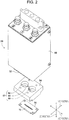
Fig. 2 is an exploded view of a plasma generating device. -
Fig. 3 is an exploded view of the plasma generating device. -
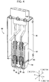
Fig. 4 is a sectional view of the plasma generating device. -
Fig. 5 is a perspective view of an antitumor aqueous solution manufacturing device. -
Fig. 6 is a side view of the antitumor aqueous solution manufacturing device. -
Fig. 7 is a side view of the antitumor aqueous solution manufacturing device. -
Fig. 8 is a perspective view of the antitumor aqueous solution manufacturing device. -
Fig. 9 is a schematic diagram of a cooling device. -
Fig. 10 is a block diagram of a control device. - An antitumor aqueous solution manufacturing device of the invention is described below in detail with reference to the drawings for example. An antitumor aqueous solution manufacturing device of this embodiment manufactures an antitumor aqueous solution by irradiating a raw material solution with plasma and thereby generating an antitumor component in the raw material solution. The antitumor aqueous solution manufacturing device of this embodiment is implemented by atmospheric-pressure
plasma irradiation device 10 described below that performs plasma irradiation under the atmospheric pressure. - Plasma irradiation is performed while the hydrogen peroxide concentration in the raw material solution is measured, and plasma irradiation is ended when the measured concentration has fallen in a predetermined concentration range. Because the hydrogen peroxide concentration correlates with the plasma irradiation conditions, controlling the hydrogen peroxide concentration provides an antitumor aqueous solution appropriately irradiated with plasma. The predetermined concentration range has appropriate values that vary in accordance with, for example, the type of tumor to which the antitumor aqueous solution is applied. The raw material solution during plasma irradiation may be left in a stationary state or in a circulation state. When plasma irradiation is performed, the raw material solution may be irradiated with plasma from above the solution surface.
- The manufactured antitumor aqueous solution can affect a tumor existing in a living body by being directly administered to the living body. The administration of the antitumor aqueous solution to the living body can employ a method of bringing the antitumor aqueous solution into contact with the tumor in a state exposed by a surgical treatment. For example, when a tumor was attempted to be removed but was not completely removed by a surgical treatment, the remaining tumor can be killed by the contact between the antitumor aqueous solution and the tumor through washing or the like during the surgical treatment.
- The raw material solution is an aqueous solution. For example, the raw material solution is desirably an aqueous solution prepared by adding a solute containing at least one component selected from disodium hydrogen phosphate (Na2HPO4), sodium hydrogen carbonate (NaHCO3), L-glutamine, L-histidine, and L-tyrosine disodium (L-tyrosine·2Na) to water. The raw material solution using the aqueous solution is irradiated with plasma and thus a highly effective antitumor aqueous solution with can be obtained. The raw material solution is desirably a living body fluid, or a culture solution for living body cells.
-
Fig. 1 illustrates atmospheric-pressureplasma irradiation device 10 of an embodiment of the invention. Atmospheric-pressureplasma irradiation device 10 irradiates a culture solution serving as a raw material solution with plasma under the atmospheric pressure. The culture solution is held in petridish 110 in a stationary state. - Atmospheric-pressure
plasma irradiation device 10 includesplasma generating device 20,cover housing 22, opening andclosing mechanism 24,stage 26 serving as a holding portion that holds the raw material solution inpetri dish 110, lifting andlowering device 28, cooling device (seeFig. 9 ) 30, purge gas supply mechanism (seeFig. 5 ) 32, oxygenconcentration detection mechanism 34, hydrogen peroxide concentration detection mechanism (seeFig. 10 ) 35,exhaust mechanism 36, and control device (seeFig. 10 ) 38. Note that a width direction of atmospheric-pressureplasma irradiation device 10 is referred to as X direction, a depth direction of atmospheric-pressureplasma irradiation device 10 is referred to as Y direction, and a direction perpendicular to the X and Y directions, that is, an up-down direction, is referred to as Z direction. - As illustrated in
Figs. 2 to 4 ,plasma generating device 20 includescover 50,upper block 52,lower block 54, one pair ofelectrodes 56, andnozzle block 58.Cover 50 substantially has a lidded rectangular tubular shape, andupper block 52 is arranged incover 50.Upper block 52 is substantially rectangular-parallelepiped and is formed of a ceramic. One pair of columnar recessedportions 60 are formed in a lower surface ofupper block 52. -
Lower block 54 is substantially rectangular-parallelepiped and is formed of a ceramic. Recessedportion 62 is formed in an upper surface oflower block 54, andrecessed portion 62 is configured of one pair of columnar recessedportions 66 and connecting recessed portion 68 that connects one pair of columnar recessedportions 66 to each other.Lower block 54 is fixed to the lower surface ofupper block 52 in a state in whichlower block 54 protrudes from a lower end ofcover 50, and columnar recessedportions 60 ofupper block 52 communicate with columnar recessedportions 66 oflower block 54. Columnar recessedportions 60 and columnar recessedportions 66 have substantially the same diameter. A bottom surface ofrecessed portion 62 has slit 70 that extends throughlower block 54 to a lower surface thereof. - One pair of
electrodes 56 are arranged in columnar spaces defined by columnar recessedportions 60 ofupper block 52 and columnar recessedportions 66 oflower block 54.Electrodes 56 have an outer diameter smaller than the inner diameter of columnar recessedportions Nozzle block 58 has a substantially flat-plate shape and is fixed to the lower surface oflower block 54.Nozzle block 58 hasemission port 72 that communicates withslit 70 oflower block 54, andemission port 72 extends throughnozzle block 58 in the up-down direction. -
Plasma generating device 20 further has processing gas supply device (seeFig. 10 ) 74. Processinggas supply device 74 supplies a processing gas in which an active gas, such as oxygen or hydrogen, is mixed with an inert gas, such as argon or nitrogen, at a given ratio; and processinggas supply device 74 is connected to the columnar spaces defined by columnar recessedportions portion 62 from the gaps betweenelectrodes 56 and columnar recessedportions 66 and from the upper area of connecting recessed portion 68. - With the structure,
plasma generating device 20 emits plasma fromemission port 72 ofnozzle block 58. In detail, the processing gas is supplied into recessedportion 62 by processinggas supply device 74. In this case, a voltage is applied to one pair ofelectrodes 56 and current flows between one pair ofelectrodes 56 in recessedportion 62. Thus, an electrical discharge occurs between one pair ofelectrodes 56, and the processing gas is plasmarized by the electrical discharge. The plasma is emitted fromemission port 72 viaslit 70. - As illustrated in
Fig. 5 , coverhousing 22 includesupper cover 76 andlower cover 78.Upper cover 76 substantially has a lidded cylindrical shape, and a lid ofupper cover 76 has a through-hole (not illustrated) with a shape corresponding tolower block 54 ofplasma generating device 20.Cover 50 ofplasma generating device 20 is fixed in a standing state on the lid ofupper cover 76 so as to cover the through-hole. Thus,lower block 54 andnozzle block 58 ofplasma generating device 20 protrude toward the inside ofupper cover 76 so as to extend in the Z direction. Accordingly, plasma generated byplasma generating device 20 is emitted in the Z direction fromemission port 72 ofnozzle block 58 toward the inside ofupper cover 76. - Moreover, a side surface of
upper cover 76 has three substantially rectangular through-holes (not illustrated) formed at three equally spaced positions, andtransparent glass plates 80 are arranged so as to close the through-holes. Accordingly, the inside ofupper cover 76 can be visually checked viaglass plates 80. -
Lower cover 78 ofcover housing 22 is substantially disk-shaped and is fixed to a casing (not illustrated) of a placing portion on which atmospheric-pressureplasma irradiation device 10 is placed.Lower cover 78 has a larger outer diameter than the outer diameter ofupper cover 76, andannular gasket 82 with the same diameter as the diameter ofupper cover 76 is arranged on an upper surface oflower cover 78. Whenupper cover 76 slides downward by opening andclosing mechanism 24,upper cover 76 comes into close contact withgasket 82, and the inside ofcover housing 22 is hermetically sealed. - In detail, as illustrated in
Figs. 6 and7 , opening andclosing mechanism 24 includes one pair ofslide mechanisms 86 and air cylinder 88. Each ofslide mechanisms 86 includessupport shaft 90 andslider 92.Support shaft 90 stands on the casing of the placing portion so as to extend in the Z direction. Moreover,slider 92 is substantially cylindrical, and is fitted ontosupport shaft 90 so as to be slidable in the axial direction ofsupport shaft 90. -
Upper cover 76 is held atslider 92 by usingupper bracket 96 andlower bracket 98. Thus,upper cover 76 is slidable in the Z direction, that is, the up-down direction. - Air cylinder 88 includes
rod 100, a piston (not illustrated), andcylinder 102.Rod 100 is arranged to extend in the Z direction, and an upper end portion ofrod 100 is fixed toupper cover 76. Moreover, a lower end portion ofrod 100 is fixed to the piston. The piston is fitted intocylinder 102 from an upper end ofcylinder 102, and slidably moves incylinder 102.Cylinder 102 is fixed to the casing of the placing portion at the lower end portion, and a predetermined amount of air is sealed incylinder 102. - Thus, air cylinder 88 functions as a damper, and
upper cover 76 is prevented from being rapidly lowered. The air pressure incylinder 102 is a pressure that can be compressed by the weight of an integrated body that slides together withupper cover 76, or more specifically, the weights ofupper cover 76,plasma generating device 20,slider 92, and another member. That is, when an operator releasesupper cover 76 whileupper cover 76 is lifted,upper cover 76 is lowered by the weight ofupper cover 76 and another member.Upper cover 76 comes into close contact withgasket 82 oflower cover 78, and as illustrated inFig. 8 , the inside ofcover housing 22 is hermetically sealed byupper cover 76 andlower cover 78. - When the operator lifts
upper cover 76, the inside ofcover housing 22 is opened. Magnets (seeFig. 1 ) 106 are fixed to an upper surface ofupper cover 76, and whenupper cover 76 is lifted,magnets 106 stick to the casing of the placing portion. Whenmagnets 106 stick to the casing of the placing portion, the lifted state ofupper cover 76, that is, the open state ofcover housing 22 is maintained. -
Stage 26 is substantially disk-shaped, andpetri dish 110 is placed on an upper surface ofstage 26. One or two hydrogen peroxide detection sensors (seeFig. 10 , not illustrated in the other drawings) 147 that are connected to hydrogen peroxideconcentration detection mechanism 35 are arranged such that hydrogenperoxide detection sensors 147 can be inserted intopetri dish 110.Stage 26 has a smaller outer diameter than the outer diameter oflower cover 78.Stage 26 is arranged on the upper surface oflower cover 78. - As illustrated in
Fig. 7 , lifting and loweringdevice 28 includessupport rod 112,rack 114,pinion 116, and electromagnetic motor (seeFig. 10 ) 117.Lower cover 78 has a through-hole (not illustrated) that extends therethough in the up-down direction, andsupport rod 112 is inserted through the through-hole.Support rod 112 has a smaller outer diameter than the inner diameter of the through-hole, andsupport rod 112 is movable in the up-down direction, that is, in the Z direction. The lower surface ofstage 26 is fixed to an upper end ofsupport rod 112. -
Rack 114 is fixed to an outer peripheral surface of a portion ofsupport rod 112 extending downward fromlower cover 78 to extend in the axial direction ofsupport rod 112.Pinion 116 meshes withrack 114, and is rotated by driving of electromagnetic motor 117.Pinion 116 is rotatably held by the casing of the placing portion. With the structure, whenpinion 116 is rotated by driving of electromagnetic motor 117,support rod 112 moves in the Z direction, andstage 26 is lifted and lowered.Gaging rod 118 stands on the upper surface oflower cover 78, at a position next to stage 26. An outer peripheral surface ofgaging rod 118 has a scale, and the height ofstage 26 in the Z direction, that is, the lifted and lowered amount ofstage 26 can be visually checked by using the scale. - As illustrated in
Fig. 9 ,cooling device 30 includescooling water channel 120,circulation device 122, andpipe 124. Coolingwater channel 120 extends through the inside ofstage 26 in the plane direction ofstage 26 to have an "angular C" shape, and is open at two positions of the outer peripheral surface ofstage 26.Circulation device 122 cools water and circulates the cooled water.Circulation device 122 is connected to coolingwater channel 120 viapipe 124. Thus, when cooling water flows instage 26,stage 26 is cooled. - As illustrated in
Fig. 5 , purgegas supply mechanism 32 includes four air joints (in the drawing, three air joints are illustrated) 130 and purge gas supply mechanism (seeFig. 10 ) 132. Fourair joints 130 are provided at four equally spaced positions at an upper end portion of a side surface ofupper cover 76, andair joints 130 are open to the inside ofupper cover 76. Purgegas supply device 132 supplies an inert gas such as nitrogen, and is connected to airjoints 130 via pipes (not illustrated). With the structure, purgegas supply mechanism 32 supplies the inert gas such as argon intoupper cover 76. - Oxygen
concentration detection mechanism 34 includes air joint 140,pipe 142, and oxygen detection sensor (seeFig. 10 ) 144.Lower cover 78 has a through-hole (not illustrated) that extends from the upper surface to the side surface oflower cover 78. Opening 146 of the through-hole at the upper surface oflower cover 78 is positioned insidegasket 82. In contrast, air joint 140 is connected to an opening of the through-hole at the side surface oflower cover 78.Oxygen detection sensor 144 detects the oxygen concentration, and is connected to air joint 140 viapipe 142. With the structure, oxygenconcentration detection mechanism 34 detects the oxygen concentration incover housing 22 whencover housing 22 is hermetically sealed. - As illustrated in
Fig. 1 ,exhaust mechanism 36 includes L-shapedpipe 150, connectingpipe 152, andmain pipe 154. As illustrated inFig. 7 ,lower cover 78 hasduct port 160 that is open to the upper surface and a lower surface oflower cover 78. The opening ofduct port 160 at the upper surface oflower cover 78 defines taperedsurface 162 having an inner diameter that increases upward. That is, when coverhousing 22 is hermetically sealed, taperedsurface 162 is inclined toward an inner wall surface ofupper cover 76. In contrast, L-shapedpipe 150 is connected to the opening ofduct port 160 at the lower surface oflower cover 78.Main pipe 154 is connected to L-shapedpipe 150 via connectingpipe 152. Note that a portion of connectingpipe 152 near L-shapedpipe 150 is not illustrated. Moreover,ozone filter 166 is arranged inmain pipe 154.Ozone filter 166 is formed of activated carbon and sucks ozone. - As illustrated in
Fig. 10 ,control device 38 includescontroller 170,multiple drive circuits 172, andselection device 173.Multiple drive circuits 172 are connected toelectrodes 56, processinggas supply device 74, electromagnetic motor 117,circulation device 122, and purgegas supply device 132.Controller 170 includes a CPU, ROM, RAM, and the like, is mainly composed of a computer, and is connected tomultiple drive circuits 172. Thus,controller 170 controls operations ofplasma generating device 20, lifting and loweringdevice 28,cooling device 30, and purgegas supply mechanism 32. Moreover,controller 170 is connected tooxygen detection sensor 144, and hydrogenperoxide detection sensor 147 of hydrogen peroxideconcentration detection mechanism 35. Thus,controller 170 acquires detection results ofoxygen detection sensor 144 and hydrogenperoxide detection sensor 147, that is, the oxygen concentration incover housing 22 and the hydrogen peroxide concentration in the raw material solution. - The RAM and ROM of
controller 170 function asstorage device 175, and store values of appropriate hydrogen peroxide concentrations that are set for each of multiple purposes of use of antitumor aqueous solutions to be manufactured. The appropriate hydrogen peroxide concentrations can be previously set by an experiment or the like. - The antitumor aqueous solution that is manufactured by
plasma irradiation device 10 of this embodiment has appropriate plasma irradiation conditions depending on the type of tumor to which the antitumor aqueous solution is applied, and the plasma irradiation conditions are handled as values of hydrogen peroxide concentrations.Selection device 173 that is connected to controldevice 38 selects the tumor to which the antitumor aqueous solution to be manufactured is applied. - In
controller 170, settingdevice 174 installed as a logic extracts values of corresponding hydrogen peroxide concentrations stored in the storage device in accordance with the type of tumor selected byselection device 173, and sets the values as a predetermined range of the values of hydrogen peroxide concentrations that are used for control in a final phase of plasma irradiation. Although not particularly limited, an example ofselection device 173 may be a keyboard, a mouse, a touch panel, or any type of switch that is generally used for a computer.Controller 170 performs plasma irradiation until the value of hydrogen peroxide concentration in the raw material solution falls within the predetermined range that has been set. As described above, a user can set appropriate hydrogen peroxide concentrations simply by selecting a type of tumor of an application target by usingselection device 173 without inputting appropriate hydrogen peroxide concentrations, and can manufacture an antitumor aqueous solution that is manufactured through plasma irradiation under appropriate conditions. - By irradiating a raw material solution with plasma, the raw material solution is activated and an antitumor aqueous solution is obtained. Plasma irradiation is performed until the hydrogen peroxide concentration in the culture solution subjected to plasma irradiation falls within an appropriate range. For the appropriate range of hydrogen peroxide concentrations, desirable hydrogen peroxide concentrations can be preparatorily obtained depending on the type of tumor to which the antitumor aqueous solution is applied. The values of hydrogen peroxide concentrations are desirably values obtained through plasma irradiation that has been started from certain initial conditions. By setting the consistent initial conditions, the correlation between the antitumor component concentration and the hydrogen peroxide concentration in the antitumor aqueous solution is possibly enhanced.
- With atmospheric-pressure
plasma irradiation device 10, using the configuration described above, by placingpetri dish 110 storing the culture solution onstage 26 and hermetically sealingcover housing 22, the culture solution can be irradiated with plasma under predetermined conditions. Hereinafter, a method of irradiating the culture solution with plasma under the predetermined conditions is described below in detail. - Specifically,
petri dish 110 storing the culture solution is placed onstage 26. Hydrogenperoxide detection sensor 147 is inserted intopetri dish 110. Then,stage 26 is lifted or lowered to a desirable height by using lifting and loweringdevice 28. Thus, the distance betweenemission port 72 of plasma and the culture solution serving as a body to be irradiated with plasma can be desirably set. The lifted or lowered height ofstage 26 can be checked by using the scale ofgaging rod 118. - Then,
upper cover 76 is lowered and coverhousing 22 is hermetically sealed. Purgegas supply mechanism 32 supplies the inert gas intocover housing 22. At this time, oxygenconcentration detection mechanism 34 detects the oxygen concentration incover housing 22. After the detected oxygen concentration has been below a previously set threshold,plasma generating device 20 emits plasma intocover housing 22. - Before plasma irradiation is started, a target to which the antitumor aqueous to be manufactured is applied, and use conditions are selected by operating
selection device 173.Setting device 174 ofcontroller 170 sets a predetermined range of values of hydrogen peroxide concentrations as a target with reference to data in the storage device based on the selected purpose of use. Plasma irradiation is performed until the hydrogen peroxide concentration inpetri dish 110 falls within the predetermined range that has been set.Setting device 174 can set, in addition to the predetermined range of the values of hydrogen peroxide concentration, other plasma irradiation conditions (for example, irradiation output, oxygen concentration, and temperature of raw material solution) in accordance with the purpose of use selected byselection device 173. - While plasma irradiation is performed, the inert gas is continuously supplied into
cover housing 22. Supplying the inert gas intocover housing 22 exhausts the air incover housing 22 to the outside ofcover housing 22. In this case, the oxygen concentration incover housing 22 is regulated, and the conditions that affect plasma irradiation are controlled. More specifically, since plasma contains active radicals, when the active radicals react with oxygen, the active radicals become ozone and decrease the effect of plasma irradiation. Regulating the oxygen concentration incover housing 22 can control the influence of the oxygen concentration on the effect of the culture solution irradiated with plasma. In addition, the culture solution can be irradiated with plasma under the same conditions. Thus, the antitumor aqueous solution having a certain antitumor effect can be efficiently manufactured. - With atmospheric-pressure
plasma irradiation device 10, as described above, the distance betweenemission port 72 of plasma and the culture solution is desirably set. Thus, the irradiation distance, which is as a plasma irradiation condition, can be optimized, and the antitumor aqueous solution having a certain antitumor effect can be efficiently manufactured. - The plasma generating device radiates plasma from above the solution surface of the culture solution in
petri dish 110. Thus, plasma is radiated in a wide range and hence the processing speed is increased. - During plasma irradiation, cooling
device 30 circulates cooling water instage 26. Coolingstage 26 restricts a temperature rise of the culture solution inpetri dish 110 by plasma irradiation, and prevents the culture solution from vaporizing. Controlling the temperature of the cooling water regulates the temperature of the culture solution during plasma irradiation. -
Lower cover 78 hasduct port 160. By this, when the inert gas is supplied intocover housing 22, the pressure incover housing 22 becomes positive pressure, and the gas is naturally exhausted from the inside ofcover housing 22. Moreover,duct port 160 oflower cover 78 has taperedsurface 162 whose inner diameter increases toward the upper surface oflower cover 78. Thus, the exhaust of the gas from the inside ofcover housing 22 can be promoted. Further,exhaust mechanism 36 is provided withozone filter 166. Thus, even when plasma reacts with oxygen and ozone is generated, the exhaust of the ozone to the outside can be prevented. - The present invention is not limited to the above-described embodiment, and can be implemented in various forms in which various changes and improvements are made based on the knowledge of those skilled in the art. More specifically, for example, while
petri dish 110 is used for holding the raw material solution according to the embodiment, another container may be used. Also, the raw material solution in the container may be circulated by a certain method. When the raw material solution is circulated, circulation can be made during plasma irradiation. The circulation enables uniform plasma irradiation on the culture solution. - The antitumor aqueous solution manufacturing device of the invention can manufacture an antitumor aqueous solution having an appropriate effect depending on the tumor to which the antitumor aqueous solution is applied.
-
- 10: atmospheric-pressure plasma irradiation device
- 20: plasma generating device
- 22: cover housing
- 26: stage (holding portion)
- 28: lifting and lowering device
- 30: cooling device
- 35: hydrogen peroxide concentration detection mechanism
- 38: control device
- 72: emission port
- 132: purge gas supply device
- 144: oxygen detection sensor
- 147: hydrogen peroxide detection sensor
Claims (6)
- An antitumor aqueous solution manufacturing device configured to manufacture an antitumor aqueous solution having an antitumor effect, comprising:a holding portion configured to hold a raw material solution in which a raw material of the antitumor aqueous solution is dissolved;a plasma generating device configured to generate plasma to be radiated on the raw material solution in the holding portion;a hydrogen peroxide detection sensor configured to measure a hydrogen peroxide concentration in the raw material solution in the holding portion; anda control device configured to control the plasma generating device,wherein the control device controls the plasma generating device such that the hydrogen peroxide concentration measured by the hydrogen peroxide detection sensor falls within a predetermined range.
- The antitumor aqueous solution manufacturing device according to Claim 1, wherein the raw material solution is an aqueous solution prepared by adding a solute containing at least one component selected from disodium hydrogen phosphate (Na2HPO4), sodium hydrogen carbonate (NaHCOs), L-glutamine, L-histidine, and L-tyrosine disodium (L-tyrosine.2Na) to water.
- The antitumor aqueous solution manufacturing device according to Claim 1 or 2, wherein the holding portion holds the raw material solution in a stationary state or in a repetitive circulation state.
- The antitumor aqueous solution manufacturing device according to any one of Claims 1 to 3,
wherein the control device includesa storage device configured to store values of appropriate hydrogen peroxide concentrations that are set for each of multiple purposes of use of the antitumor aqueous solution,a selection device configured to select one of the multiple purposes of use, anda setting device configured to set the predetermined range based on the values of the appropriate hydrogen peroxide concentrations corresponding to the purpose of use selected by the selection device. - The antitumor aqueous solution manufacturing device according to any one of Claims 1 to 4, wherein the plasma generating device radiates plasma from above a solution surface of the raw material solution held in the holding portion.
- The antitumor aqueous solution manufacturing device according to any one of Claims 1 to 5, wherein the raw material solution is a living body fluid, or a culture solution for living body cells.
Applications Claiming Priority (1)
| Application Number | Priority Date | Filing Date | Title |
|---|---|---|---|
| PCT/JP2016/071192 WO2018016014A1 (en) | 2016-07-19 | 2016-07-19 | Antitumor aqueous solution manufacturing device |
Publications (3)
| Publication Number | Publication Date |
|---|---|
| EP3488867A1 true EP3488867A1 (en) | 2019-05-29 |
| EP3488867A4 EP3488867A4 (en) | 2020-04-01 |
| EP3488867B1 EP3488867B1 (en) | 2025-08-06 |
Family
ID=60992365
Family Applications (1)
| Application Number | Title | Priority Date | Filing Date |
|---|---|---|---|
| EP16909489.3A Active EP3488867B1 (en) | 2016-07-19 | 2016-07-19 | Antitumor aqueous solution manufacturing device |
Country Status (3)
| Country | Link |
|---|---|
| EP (1) | EP3488867B1 (en) |
| JP (1) | JP6823656B2 (en) |
| WO (1) | WO2018016014A1 (en) |
Cited By (2)
| Publication number | Priority date | Publication date | Assignee | Title |
|---|---|---|---|---|
| EP3895738A1 (en) * | 2020-04-16 | 2021-10-20 | Erbe Elektromedizin GmbH | Device and method for plasma activation of a liquid |
| RU2832940C2 (en) * | 2020-04-16 | 2025-01-10 | Эрбе Электромедицин Гмбх | Apparatus and method for plasma activation of liquid |
Family Cites Families (6)
| Publication number | Priority date | Publication date | Assignee | Title |
|---|---|---|---|---|
| JP3899543B2 (en) * | 1996-02-05 | 2007-03-28 | セイコーエプソン株式会社 | Surface treatment method and apparatus |
| WO2013128905A1 (en) * | 2012-02-27 | 2013-09-06 | 国立大学法人名古屋大学 | Anti-tumor aqueous solution, anti-cancer agent, and methods for producing said aqueous solution and said anti-cancer agent |
| JP2014113517A (en) * | 2012-12-06 | 2014-06-26 | Samsung R&D Institute Japan Co Ltd | Water quality control apparatus and water quality control method |
| JP2014189441A (en) * | 2013-03-27 | 2014-10-06 | Dainippon Screen Mfg Co Ltd | Hydrogen peroxide solution generation device, substrate processing unit, and hydrogen peroxide solution generation method |
| WO2016035339A1 (en) * | 2014-09-04 | 2016-03-10 | 国立大学法人名古屋大学 | Plasma generation device and method for producing anti-tumor aqueous solution |
| EP3344018B1 (en) * | 2015-08-28 | 2020-12-09 | FUJI Corporation | Plasma irradiation device |
-
2016
- 2016-07-19 WO PCT/JP2016/071192 patent/WO2018016014A1/en not_active Ceased
- 2016-07-19 JP JP2018528135A patent/JP6823656B2/en active Active
- 2016-07-19 EP EP16909489.3A patent/EP3488867B1/en active Active
Cited By (2)
| Publication number | Priority date | Publication date | Assignee | Title |
|---|---|---|---|---|
| EP3895738A1 (en) * | 2020-04-16 | 2021-10-20 | Erbe Elektromedizin GmbH | Device and method for plasma activation of a liquid |
| RU2832940C2 (en) * | 2020-04-16 | 2025-01-10 | Эрбе Электромедицин Гмбх | Apparatus and method for plasma activation of liquid |
Also Published As
| Publication number | Publication date |
|---|---|
| WO2018016014A1 (en) | 2018-01-25 |
| JPWO2018016014A1 (en) | 2019-05-09 |
| EP3488867B1 (en) | 2025-08-06 |
| JP6823656B2 (en) | 2021-02-03 |
| EP3488867A4 (en) | 2020-04-01 |
Similar Documents
| Publication | Publication Date | Title |
|---|---|---|
| US12033836B2 (en) | Nitriding apparatus and nitriding method | |
| US8852966B2 (en) | Heat treatment method and heat treatment apparatus of thin film | |
| US10421938B2 (en) | Plasma induced mutation breeding device | |
| JP2021176504A (en) | Device and method for plasma activating liquid | |
| EP3488867B1 (en) | Antitumor aqueous solution manufacturing device | |
| US20190267262A1 (en) | Light irradiation type heat treatment apparatus and heat treatment method | |
| WO2010094323A1 (en) | An apparatus for the measurement of a concentration of a charged species in a sample | |
| Liu et al. | Indirect treatment effects of water–air MHCD jet on the inactivation of Penicillium Digitatum suspension | |
| CN116137806A (en) | Plasma treatment device | |
| JP2008188032A (en) | Plasma sterilization apparatus and plasma sterilization method using the apparatus | |
| JP5083825B2 (en) | Plasma discharge device in liquid | |
| EP3502050B1 (en) | Method for producing aqueous hydrogen peroxide | |
| JP6697470B2 (en) | Plasma irradiation device | |
| JP6973976B2 (en) | Anti-tumor aqueous solution manufacturing equipment | |
| Ni et al. | Plasma inactivation of Escherichia coli cells by atmospheric pressure air brush-shape plasma | |
| KR101669961B1 (en) | Hydrogen peroxide plasma sterilizing apparatus | |
| JPWO2018096606A1 (en) | Plasma generator | |
| KR102660970B1 (en) | Apparatus for sterilization and plasma treatment | |
| WO2023162102A1 (en) | Plasma irradiation apparatus and plasma-treated liquid production method | |
| US20250168960A1 (en) | Method for producing plasma processed liquid and plasma irradiation apparatus | |
| KR102611478B1 (en) | Apparatus for plasma treatment | |
| KR20240138451A (en) | Apparatus for plasma surface treatment in atmospheric and method for controlling the same | |
| JP2016035860A (en) | Plasma active oxygen confirmatory reagent, and method for confirming range of effect of active oxygen generated by plasma | |
| Yang | Experimental Study of Neutral Radical’s Effect on Inactivation of Spore-forming Microorganisms by Low Pressure N2/O2 Surface-wave Plasma | |
| JP2014024784A (en) | Sterilization solution, and sterilization solution production apparatus |
Legal Events
| Date | Code | Title | Description |
|---|---|---|---|
| STAA | Information on the status of an ep patent application or granted ep patent |
Free format text: STATUS: THE INTERNATIONAL PUBLICATION HAS BEEN MADE |
|
| PUAI | Public reference made under article 153(3) epc to a published international application that has entered the european phase |
Free format text: ORIGINAL CODE: 0009012 |
|
| STAA | Information on the status of an ep patent application or granted ep patent |
Free format text: STATUS: REQUEST FOR EXAMINATION WAS MADE |
|
| 17P | Request for examination filed |
Effective date: 20190118 |
|
| AK | Designated contracting states |
Kind code of ref document: A1 Designated state(s): AL AT BE BG CH CY CZ DE DK EE ES FI FR GB GR HR HU IE IS IT LI LT LU LV MC MK MT NL NO PL PT RO RS SE SI SK SM TR |
|
| AX | Request for extension of the european patent |
Extension state: BA ME |
|
| DAV | Request for validation of the european patent (deleted) | ||
| DAX | Request for extension of the european patent (deleted) | ||
| A4 | Supplementary search report drawn up and despatched |
Effective date: 20200303 |
|
| RIC1 | Information provided on ipc code assigned before grant |
Ipc: B01J 19/08 20060101ALI20200226BHEP Ipc: A61K 33/00 20060101ALI20200226BHEP Ipc: B01J 12/00 20060101ALI20200226BHEP Ipc: B01J 37/34 20060101ALN20200226BHEP Ipc: A61K 41/00 20200101AFI20200226BHEP Ipc: A61P 35/00 20060101ALI20200226BHEP |
|
| STAA | Information on the status of an ep patent application or granted ep patent |
Free format text: STATUS: EXAMINATION IS IN PROGRESS |
|
| 17Q | First examination report despatched |
Effective date: 20220601 |
|
| P01 | Opt-out of the competence of the unified patent court (upc) registered |
Effective date: 20230328 |
|
| GRAP | Despatch of communication of intention to grant a patent |
Free format text: ORIGINAL CODE: EPIDOSNIGR1 |
|
| STAA | Information on the status of an ep patent application or granted ep patent |
Free format text: STATUS: GRANT OF PATENT IS INTENDED |
|
| RIC1 | Information provided on ipc code assigned before grant |
Ipc: B01J 37/34 20060101ALN20250307BHEP Ipc: B01J 19/08 20060101ALI20250307BHEP Ipc: B01J 12/00 20060101ALI20250307BHEP Ipc: A61P 35/00 20060101ALI20250307BHEP Ipc: A61K 33/00 20060101ALI20250307BHEP Ipc: A61K 41/00 20060101AFI20250307BHEP |
|
| INTG | Intention to grant announced |
Effective date: 20250324 |
|
| GRAS | Grant fee paid |
Free format text: ORIGINAL CODE: EPIDOSNIGR3 |
|
| GRAA | (expected) grant |
Free format text: ORIGINAL CODE: 0009210 |
|
| STAA | Information on the status of an ep patent application or granted ep patent |
Free format text: STATUS: THE PATENT HAS BEEN GRANTED |
|
| AK | Designated contracting states |
Kind code of ref document: B1 Designated state(s): AL AT BE BG CH CY CZ DE DK EE ES FI FR GB GR HR HU IE IS IT LI LT LU LV MC MK MT NL NO PL PT RO RS SE SI SK SM TR |
|
| REG | Reference to a national code |
Ref country code: GB Ref legal event code: FG4D |
|
| REG | Reference to a national code |
Ref country code: CH Ref legal event code: EP |
|
| REG | Reference to a national code |
Ref country code: IE Ref legal event code: FG4D |
|
| REG | Reference to a national code |
Ref country code: DE Ref legal event code: R096 Ref document number: 602016093186 Country of ref document: DE |
|
| REG | Reference to a national code |
Ref country code: NL Ref legal event code: MP Effective date: 20250806 |
|
| PG25 | Lapsed in a contracting state [announced via postgrant information from national office to epo] |
Ref country code: IS Free format text: LAPSE BECAUSE OF FAILURE TO SUBMIT A TRANSLATION OF THE DESCRIPTION OR TO PAY THE FEE WITHIN THE PRESCRIBED TIME-LIMIT Effective date: 20251206 |
|
| PG25 | Lapsed in a contracting state [announced via postgrant information from national office to epo] |
Ref country code: NO Free format text: LAPSE BECAUSE OF FAILURE TO SUBMIT A TRANSLATION OF THE DESCRIPTION OR TO PAY THE FEE WITHIN THE PRESCRIBED TIME-LIMIT Effective date: 20251106 |
|
| REG | Reference to a national code |
Ref country code: LT Ref legal event code: MG9D |
|
| PG25 | Lapsed in a contracting state [announced via postgrant information from national office to epo] |
Ref country code: PT Free format text: LAPSE BECAUSE OF FAILURE TO SUBMIT A TRANSLATION OF THE DESCRIPTION OR TO PAY THE FEE WITHIN THE PRESCRIBED TIME-LIMIT Effective date: 20251209 |
|
| PG25 | Lapsed in a contracting state [announced via postgrant information from national office to epo] |
Ref country code: FI Free format text: LAPSE BECAUSE OF FAILURE TO SUBMIT A TRANSLATION OF THE DESCRIPTION OR TO PAY THE FEE WITHIN THE PRESCRIBED TIME-LIMIT Effective date: 20250806 |
|
| PG25 | Lapsed in a contracting state [announced via postgrant information from national office to epo] |
Ref country code: NL Free format text: LAPSE BECAUSE OF FAILURE TO SUBMIT A TRANSLATION OF THE DESCRIPTION OR TO PAY THE FEE WITHIN THE PRESCRIBED TIME-LIMIT Effective date: 20250806 Ref country code: HR Free format text: LAPSE BECAUSE OF FAILURE TO SUBMIT A TRANSLATION OF THE DESCRIPTION OR TO PAY THE FEE WITHIN THE PRESCRIBED TIME-LIMIT Effective date: 20250806 |
|
| PG25 | Lapsed in a contracting state [announced via postgrant information from national office to epo] |
Ref country code: GR Free format text: LAPSE BECAUSE OF FAILURE TO SUBMIT A TRANSLATION OF THE DESCRIPTION OR TO PAY THE FEE WITHIN THE PRESCRIBED TIME-LIMIT Effective date: 20251107 |
|
| PG25 | Lapsed in a contracting state [announced via postgrant information from national office to epo] |
Ref country code: SE Free format text: LAPSE BECAUSE OF FAILURE TO SUBMIT A TRANSLATION OF THE DESCRIPTION OR TO PAY THE FEE WITHIN THE PRESCRIBED TIME-LIMIT Effective date: 20250806 |
|
| PG25 | Lapsed in a contracting state [announced via postgrant information from national office to epo] |
Ref country code: LV Free format text: LAPSE BECAUSE OF FAILURE TO SUBMIT A TRANSLATION OF THE DESCRIPTION OR TO PAY THE FEE WITHIN THE PRESCRIBED TIME-LIMIT Effective date: 20250806 |
|
| PG25 | Lapsed in a contracting state [announced via postgrant information from national office to epo] |
Ref country code: BG Free format text: LAPSE BECAUSE OF FAILURE TO SUBMIT A TRANSLATION OF THE DESCRIPTION OR TO PAY THE FEE WITHIN THE PRESCRIBED TIME-LIMIT Effective date: 20250806 Ref country code: PL Free format text: LAPSE BECAUSE OF FAILURE TO SUBMIT A TRANSLATION OF THE DESCRIPTION OR TO PAY THE FEE WITHIN THE PRESCRIBED TIME-LIMIT Effective date: 20250806 |
|
| PG25 | Lapsed in a contracting state [announced via postgrant information from national office to epo] |
Ref country code: RS Free format text: LAPSE BECAUSE OF FAILURE TO SUBMIT A TRANSLATION OF THE DESCRIPTION OR TO PAY THE FEE WITHIN THE PRESCRIBED TIME-LIMIT Effective date: 20251106 |
|
| PG25 | Lapsed in a contracting state [announced via postgrant information from national office to epo] |
Ref country code: ES Free format text: LAPSE BECAUSE OF FAILURE TO SUBMIT A TRANSLATION OF THE DESCRIPTION OR TO PAY THE FEE WITHIN THE PRESCRIBED TIME-LIMIT Effective date: 20250806 |
|
| REG | Reference to a national code |
Ref country code: AT Ref legal event code: MK05 Ref document number: 1821024 Country of ref document: AT Kind code of ref document: T Effective date: 20250806 |
|
| PG25 | Lapsed in a contracting state [announced via postgrant information from national office to epo] |
Ref country code: SM Free format text: LAPSE BECAUSE OF FAILURE TO SUBMIT A TRANSLATION OF THE DESCRIPTION OR TO PAY THE FEE WITHIN THE PRESCRIBED TIME-LIMIT Effective date: 20250806 |
|
| PG25 | Lapsed in a contracting state [announced via postgrant information from national office to epo] |
Ref country code: DK Free format text: LAPSE BECAUSE OF FAILURE TO SUBMIT A TRANSLATION OF THE DESCRIPTION OR TO PAY THE FEE WITHIN THE PRESCRIBED TIME-LIMIT Effective date: 20250806 |
|
| PG25 | Lapsed in a contracting state [announced via postgrant information from national office to epo] |
Ref country code: AT Free format text: LAPSE BECAUSE OF FAILURE TO SUBMIT A TRANSLATION OF THE DESCRIPTION OR TO PAY THE FEE WITHIN THE PRESCRIBED TIME-LIMIT Effective date: 20250806 |
|
| PG25 | Lapsed in a contracting state [announced via postgrant information from national office to epo] |
Ref country code: IT Free format text: LAPSE BECAUSE OF FAILURE TO SUBMIT A TRANSLATION OF THE DESCRIPTION OR TO PAY THE FEE WITHIN THE PRESCRIBED TIME-LIMIT Effective date: 20250806 |
|
| PG25 | Lapsed in a contracting state [announced via postgrant information from national office to epo] |
Ref country code: CZ Free format text: LAPSE BECAUSE OF FAILURE TO SUBMIT A TRANSLATION OF THE DESCRIPTION OR TO PAY THE FEE WITHIN THE PRESCRIBED TIME-LIMIT Effective date: 20250806 |
|
| PG25 | Lapsed in a contracting state [announced via postgrant information from national office to epo] |
Ref country code: EE Free format text: LAPSE BECAUSE OF FAILURE TO SUBMIT A TRANSLATION OF THE DESCRIPTION OR TO PAY THE FEE WITHIN THE PRESCRIBED TIME-LIMIT Effective date: 20250806 Ref country code: SK Free format text: LAPSE BECAUSE OF FAILURE TO SUBMIT A TRANSLATION OF THE DESCRIPTION OR TO PAY THE FEE WITHIN THE PRESCRIBED TIME-LIMIT Effective date: 20250806 |