EP3488812B1 - Verfahren zum verformen eines kieferorthopädischen drahtes aus einem formgedächtnismaterial und zugehöriger draht - Google Patents
Verfahren zum verformen eines kieferorthopädischen drahtes aus einem formgedächtnismaterial und zugehöriger draht Download PDFInfo
- Publication number
- EP3488812B1 EP3488812B1 EP18211536.0A EP18211536A EP3488812B1 EP 3488812 B1 EP3488812 B1 EP 3488812B1 EP 18211536 A EP18211536 A EP 18211536A EP 3488812 B1 EP3488812 B1 EP 3488812B1
- Authority
- EP
- European Patent Office
- Prior art keywords
- wire
- orthodontic
- brackets
- baking
- fixing sections
- Prior art date
- Legal status (The legal status is an assumption and is not a legal conclusion. Google has not performed a legal analysis and makes no representation as to the accuracy of the status listed.)
- Active
Links
Images


Classifications
-
- A—HUMAN NECESSITIES
- A61—MEDICAL OR VETERINARY SCIENCE; HYGIENE
- A61C—DENTISTRY; APPARATUS OR METHODS FOR ORAL OR DENTAL HYGIENE
- A61C7/00—Orthodontics, i.e. obtaining or maintaining the desired position of teeth, e.g. by straightening, evening, regulating, separating, or by correcting malocclusions
- A61C7/002—Orthodontic computer assisted systems
-
- A—HUMAN NECESSITIES
- A61—MEDICAL OR VETERINARY SCIENCE; HYGIENE
- A61C—DENTISTRY; APPARATUS OR METHODS FOR ORAL OR DENTAL HYGIENE
- A61C7/00—Orthodontics, i.e. obtaining or maintaining the desired position of teeth, e.g. by straightening, evening, regulating, separating, or by correcting malocclusions
- A61C7/12—Brackets; Arch wires; Combinations thereof; Accessories therefor
- A61C7/20—Arch wires
-
- A—HUMAN NECESSITIES
- A61—MEDICAL OR VETERINARY SCIENCE; HYGIENE
- A61C—DENTISTRY; APPARATUS OR METHODS FOR ORAL OR DENTAL HYGIENE
- A61C7/00—Orthodontics, i.e. obtaining or maintaining the desired position of teeth, e.g. by straightening, evening, regulating, separating, or by correcting malocclusions
- A61C7/12—Brackets; Arch wires; Combinations thereof; Accessories therefor
- A61C7/28—Securing arch wire to bracket
- A61C7/282—Buccal tubes
-
- A—HUMAN NECESSITIES
- A61—MEDICAL OR VETERINARY SCIENCE; HYGIENE
- A61C—DENTISTRY; APPARATUS OR METHODS FOR ORAL OR DENTAL HYGIENE
- A61C13/00—Dental prostheses; Making same
- A61C13/0003—Making bridge-work, inlays, implants or the like
- A61C13/0004—Computer-assisted sizing or machining of dental prostheses
-
- A—HUMAN NECESSITIES
- A61—MEDICAL OR VETERINARY SCIENCE; HYGIENE
- A61C—DENTISTRY; APPARATUS OR METHODS FOR ORAL OR DENTAL HYGIENE
- A61C2201/00—Material properties
- A61C2201/007—Material properties using shape memory effect
-
- A—HUMAN NECESSITIES
- A61—MEDICAL OR VETERINARY SCIENCE; HYGIENE
- A61C—DENTISTRY; APPARATUS OR METHODS FOR ORAL OR DENTAL HYGIENE
- A61C9/00—Impression cups, i.e. impression trays; Impression methods
- A61C9/004—Means or methods for taking digitized impressions
Definitions
- the invention relates to a method for deforming an orthodontic wire made from a shape memory material and an associated wire.
- the invention also relates to a method for producing an orthodontic wire by means of the method.
- brackets are glued to the patient's teeth to be treated and connected to one another by an orthodontic wire.
- the brackets have a pad for connection to the tooth and a bracket body that receives the archwire.
- orthodontic wires made of a shape memory material are often inserted into the brackets in order to achieve a "rough" alignment of the teeth. It is only towards the end of the orthodontic treatment that steel wires, for example, are used to move the teeth as precisely as possible into a defined position.
- the most important shape memory materials include Cu-Zn-X (X: Si, Sn, Al) alloys and the intermetallic NiTi alloy (nickel content of approx. 55% by weight), with the NiTi alloy being more technological due to its more favorable properties could gain meaning.
- the shape memory effect is based on a thermoelastic martensite transformation, a reversible phase transformation caused by the shear of the lattice planes. The cooling of the high-temperature phase, called austenite, below the alloy-specific martensite starting temperature leads to the phase transformation without any change in shape and without irreversible plastic deformation, as is the case with steels.
- Shape memory alloys can be easily deformed in the martensitic state; the reversible deformation can be up to 8% for NiTi. This deformation is permanent as long as the alloy is in the martensitic state. The heating to a temperature above the alloy-specific austenite start temperature then leads to the restoration of the original shape.
- the DE 195 40 755 C2 describes the generic production of an arch wire from shape memory material by plastering in transmission elements that are inserted into slots of brackets on a model of a target configuration, detaching the transmission elements from the slots, replacing sections of the transmission elements with wire receiving devices and then placing an arch wire in them Heating for permanent deformation.
- an orthodontic wire from a shape memory material into a target geometry In order to convert an orthodontic wire from a shape memory material into a target geometry, it is brought into the desired target geometry in a special baking pan and then heated to a transition temperature specific for the shape memory material. The orthodontic wire is then cooled again and placed in an orthodontic appliance of a patient, for example a fixed lingual or Buccal brackets, inserted under deformation. The orthodontic wire is heated again in the patient's mouth and remembers its target geometry, into which it then wants to deform. During this deformation, the orthodontic wire exerts a force on the brackets, causing the associated teeth to move.
- a disadvantage of deforming an orthodontic wire from a shape memory material into a target geometry is that the method is very complex and therefore costly.
- the DE 698 15 155 T2 describes the calculation of forces to be exerted by an arch wire in a virtual model
- the US 2004/0083611 A1 describes the production of a holder for an orthodontic wire on the basis of a computer-aided calculation of the numerical description of the shape of the wire.
- the numerical description of the wire shape is used to produce a shape in which the wire is inserted for fixation.
- the U.S. 5,456,600 A describes the calculation of the shape of an arch wire in the form of a computer model. On the basis of the computer model, a wire can then be shaped or a shape for heating a wire can be milled, which holds the wire for a heating step.
- the US 2008/0254403 A1 describes the manufacture of a mold for holding an orthodontic wire, in which wire fixing portions are milled into the convex outer surface of a shaped metal piece, on the basis of a computer model for the arch wire
- the DE 10 2006 048 063 A1 describes brackets with two slots each for holding archwires and states that an archwire can be produced by calculating its geometry from a digital representation of individual tooth segments and then forming the archwire on the basis of its calculated geometry.
- the object of the present invention is to provide an alternative method for producing an orthodontic wire from shape memory material in a target geometry, in particular to specify a simpler and more cost-effective method which leads to an orthodontic wire from a shape memory material in a target geometry.
- step 1a a target set-up made of plaster of paris or a virtual target set-up is advantageously created.
- step 1b lingual brackets are preferably arranged on the teeth of the target set-up to be treated.
- a two-dimensional photo is advantageously made in step 1c), in particular using a camera with optics.
- a band of light is preferably projected into the target set-up, which shows the focal plane of the optics for taking the photo, and the band of light is more preferably projected into the slot plane, whereby the slots are shown sharply in the photo .
- a digital photo is advantageously made in step 1c).
- a digital photo or a scan of an analog photo is advantageously loaded into the data processing system in step 1d).
- a computer in particular a desktop PC, is preferably used as the data processing system.
- step 1e) is advantageously carried out manually or automatically, in particular with the aid of morphing algorithms.
- the position of at least one slot in the occlusal plane can advantageously be changed by hand, in particular in the mesial, distal, lingual or buccal direction or combinations thereof, in particular rotations.
- the length of at least one slot can be increased or decreased mesially and / or distally.
- step 1f It is advantageous to export in step 1f) and to write the data to a computer file.
- a baking pan is made from a metal plate, in particular made from steel or aluminum.
- step 1g the wire fixing sections for the wire are milled into the metal plate and a free space for the wire is milled between adjacent wire fixing sections in which the wire is not held.
- the bottoms of the wire fixing sections and the bottoms of the free spaces are milled to the same height, so that the wire can be placed flat in the baking pan.
- the wire is preferably inserted into the baking pan by hand in step 1h).
- a plaster cast of a patient's lower jaw is made for orthodontic treatment.
- the plaster cast is sawed up and the teeth are separated.
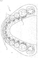
- the teeth are then placed in a target set-up 3, see FIG. Fig. 1 , arranged, which should show the desired treatment result at the end of the treatment.
- Lingual brackets 5 are glued to the teeth 7.
- all slots 5S of the lingual brackets 5 i.wstl. lie in one plane, the so-called slot plane, as in Fig. 1 shown.
- the target set-up 3 of the Fig. 1 a photo (schematic in Fig. 2 ) created from the top view:
- the target set-up 3 is arranged centrally under a dome lighting, to achieve a uniform illumination of the same.
- a camera with optics is aimed at the target set-up 3 in order to take a photo of the same from the top view.
- a projector for a laser tape 17 is assigned to the camera, the laser tape 17 showing the focal plane of the optics of the camera.
- the vertical height of the target set-up 3 is adjusted with the aid of the laser band 17 so that the slot plane of the lingual brackets 5 of the target set-up 3 with the laser band 17 is at a vertical height.
- FIG. 2 shows schematically the photo of the target set-up 3 of FIG Fig. 1 from the top view.
- the photo from the camera in this case a digital camera
- the software is mainly used to identify and determine the position of the individual slots and then output them.
- the patient is entered in the software with his patient-specific data, such as name and date of birth.
- the photo of a target set-up of a lower jaw or an upper jaw is to be edited.
- the photo of a target set-up 3 of a lower jaw is to be edited and then the storage location of the photo on the computer is specified, whereupon the photo is loaded into the software.
- the screen is divided into two parts: The upper half shows the recording of the Fig. 2 shown (a 2dim figure 9 of the target set-up with brackets in plan view). In the lower half there is a matrix in which a column is provided for each tooth of the lower jaw (from 47 to 41 and 31 to 37). In another column (in Fig. 3 far left) individual parameters are listed line by line for each of these teeth, for which values can be entered for the individual teeth, as described below.
- the software now knows for which tooth the position of the slot of the bracket arranged on the tooth is to be identified.
- brackets from different manufacturers with their respective slot dimensions are stored in the software for each tooth and in a next step the software asks the user which bracket from which company is arranged on the tooth by first entering the manufacturer and then the bracket model from the user is queried. After the user has informed the software which bracket type from which manufacturer is placed on the tooth, this step is finished. The software now knows which bracket and which slot dimensions are assigned to the tooth.
- the software now knows at which point for which tooth which bracket is roughly seated, and at this point it fades in a base slot body 5B of the corresponding bracket 5 and an associated crosshair 19, see FIG. Fig. 4 .
- the base slot body 5B generally reflects the inner contour of the slot 5S of the bracket 5 and is a rectangle in the present case.
- the two lines of the crosshair 19 each run parallel to a short or long side of the rectangular base plumb body 5B and the center of the crosshair 19 lies in the center of gravity of the basic plumb bob body 5B.
- the crosshair 19 serves as an orientation aid in order to position the base slot body 5B in the slot 5S of the bracket 5 of the tooth 47 by hand in a next step, ie to bring the base slot body 5B into congruence with the inner contour of the slot 5S of the bracket 5 in the photo.
- the base slot body 5S is moved and rotated in the photo using the mouse until the base slot body 5S is aligned with the inner contour of the slot 5S in the photo, as for example in FIG Fig. 4 for teeth 42 and 43 shown.
- the scale of the image of the same in the photo is known and the base slot body 5B in the software is matched to this scale, which means that the base slot body is covered 5S and the slot 5S in the photo.
- the position of the slot 5S is now defined with the aid of the base slot body 5B for the bracket 5 of the tooth 47 and the associated data are automatically stored in the software.
- the data stored in the software include at least: Tooth 47 and position and dimensions of slot 5S.
- the bracket type and bracket manufacturer can also be saved.
- the in Fig. 3 The matrix shown below allows you to change the value of the parameters listed there for each slot of a bracket of each tooth: If, in one example, you want to move the position of the slot mesially or distally, you can enter the in Fig. 3 Enter the required value in mm, which is also required, in the table shown below.
- the desired value in mm can be entered in column 47 in the line "Sliding travel mesial" (fifth line) which is additionally desired.
- the software now writes all data to a file in the next step.
- the file therefore contains at least for each tooth to be treated: the number of the tooth, the position and dimensions of the slot 5S of the associated bracket 5, including the correction values made.
- further data such as the name of the patient, the bracket type and the bracket manufacturer can also be saved.
- a baking mold 11 for the orthodontic wire 1 is created as follows: An aluminum plate with the dimensions 79.5mm x 79.5mm x 2.5mm is inserted into a CNC milling machine and fixed there. The aluminum plate has six flat surfaces.
- the above-mentioned file (with the data on the position, etc. of the slots) is also loaded into the CNC milling machine.
- FIG. 5a shows a development of the arch shape.
- the milling head 21 does not mill the arch shape into the aluminum plate at one level, but leaves areas that correspond to the slots and in which the orthodontic wire 1 must be held during baking, the so-called wire fixing sections 13.
- the Figure 5a shows accordingly several free spaces 15 and between the free spaces 15 raised areas.
- the milling head 21 After the milling head 21 has milled the arch shape into the aluminum plate, it is automatically exchanged for one with a smaller diameter, the diameter of which is slightly larger than that of the orthodontic wire 1.
- This milling head mills a floor 13B in the raised areas formed between two free spaces, whereby wire fixing sections 13 are formed between the free spaces 15 in which the orthodontic wire 1 is held during the baking thereof.
- the aluminum plate now has wire fixing portions 13 by which the orthodontic wire 1 can be held, and spaces 15 within which the orthodontic wire 1 cannot be held.
- the wire fixing sections 13 correspond to the later slots 5S of the brackets.
- the aluminum plate forms the baking mold 11 for the orthodontic wire 1.
- Fig. 6 the finished baking pan is shown in plan view with its wire fixing sections 13 and its free spaces 15. Furthermore, the creation date of the baking pan and the surname and first name of the patient and a case number are milled into the baking pan 11, the latter also including the indication UK to indicate that it is the patient's lower jaw model.
- the orthodontic wire 1 is inserted into the baking mold 11 by hand, i.e. the orthodontic wire 1 is inserted into the wire fixing sections 13 and then lies flat on the bottoms 13B and 15B.
- Fig. 7 shows the baking pan of the Fig. 6 , in which an orthodontic wire 1 is also inserted.
- the distal wire sections protruding after the last wire fixing section 13 can be shortened by the practitioner as required.
- the orthodontic wire 1 arranged in this way in the baking mold 11 is baked in an oven in the baking mold 11, as a result of which the orthodontic wire 1 is programmed to this geometry, i.e. the desired target geometry.
- the orthodontic wire 1 can now be inserted into an orthodontic appliance of a patient.
- orthodontic apparatus is to be understood as meaning the arrangement of lingual or buccal brackets on a patient's teeth to be treated orthodontically.
- the target geometry is the geometry of the orthodontic wire in which the treating orthodontist wants the orthodontic wire so that it causes the desired movement of the teeth to be treated when used in the orthodontic appliance.
- lingual brackets are preferably placed on the teeth to be treated.
- buccal brackets can also be placed on the teeth.
Landscapes
- Health & Medical Sciences (AREA)
- Life Sciences & Earth Sciences (AREA)
- Oral & Maxillofacial Surgery (AREA)
- Dentistry (AREA)
- Epidemiology (AREA)
- Animal Behavior & Ethology (AREA)
- General Health & Medical Sciences (AREA)
- Public Health (AREA)
- Veterinary Medicine (AREA)
- General Engineering & Computer Science (AREA)
- Engineering & Computer Science (AREA)
- Dental Tools And Instruments Or Auxiliary Dental Instruments (AREA)
- Dental Prosthetics (AREA)
Applications Claiming Priority (3)
| Application Number | Priority Date | Filing Date | Title |
|---|---|---|---|
| DE102011081151A DE102011081151A1 (de) | 2011-08-17 | 2011-08-17 | Verfahren zum Verformen eines kieferorthopädischen Drahtes aus einem Formgedächtnismaterial und zugehöriger Draht |
| PCT/EP2012/065190 WO2013023935A1 (de) | 2011-08-17 | 2012-08-02 | Verfahren zum verformen eines kieferorthopädischen drahtes aus einem formgedächtnismaterial und zugehöriger draht |
| EP12745474.2A EP2744440B1 (de) | 2011-08-17 | 2012-08-02 | Verfahren zum verformen eines kieferorthopädischen drahtes aus einem formgedächtnismaterial |
Related Parent Applications (2)
| Application Number | Title | Priority Date | Filing Date |
|---|---|---|---|
| EP12745474.2A Division-Into EP2744440B1 (de) | 2011-08-17 | 2012-08-02 | Verfahren zum verformen eines kieferorthopädischen drahtes aus einem formgedächtnismaterial |
| EP12745474.2A Division EP2744440B1 (de) | 2011-08-17 | 2012-08-02 | Verfahren zum verformen eines kieferorthopädischen drahtes aus einem formgedächtnismaterial |
Publications (2)
| Publication Number | Publication Date |
|---|---|
| EP3488812A1 EP3488812A1 (de) | 2019-05-29 |
| EP3488812B1 true EP3488812B1 (de) | 2021-03-31 |
Family
ID=46640033
Family Applications (2)
| Application Number | Title | Priority Date | Filing Date |
|---|---|---|---|
| EP18211536.0A Active EP3488812B1 (de) | 2011-08-17 | 2012-08-02 | Verfahren zum verformen eines kieferorthopädischen drahtes aus einem formgedächtnismaterial und zugehöriger draht |
| EP12745474.2A Active EP2744440B1 (de) | 2011-08-17 | 2012-08-02 | Verfahren zum verformen eines kieferorthopädischen drahtes aus einem formgedächtnismaterial |
Family Applications After (1)
| Application Number | Title | Priority Date | Filing Date |
|---|---|---|---|
| EP12745474.2A Active EP2744440B1 (de) | 2011-08-17 | 2012-08-02 | Verfahren zum verformen eines kieferorthopädischen drahtes aus einem formgedächtnismaterial |
Country Status (7)
| Country | Link |
|---|---|
| US (1) | US9566133B2 (enExample) |
| EP (2) | EP3488812B1 (enExample) |
| JP (1) | JP6050353B2 (enExample) |
| DE (1) | DE102011081151A1 (enExample) |
| ES (1) | ES2728915T3 (enExample) |
| TR (1) | TR201907768T4 (enExample) |
| WO (1) | WO2013023935A1 (enExample) |
Families Citing this family (25)
| Publication number | Priority date | Publication date | Assignee | Title |
|---|---|---|---|---|
| ES2874777T3 (es) | 2012-10-30 | 2021-11-05 | Univ Southern California | Aparato de ortodoncia con arco de alambre encajado a presión, antideslizante |
| DE102013209735A1 (de) * | 2013-05-24 | 2014-11-27 | Dw Lingual Systems Gmbh | Verfahren zum Herstellen eines patientenspezifischen Ersatzbrackets für eine kieferorthopädische Behandlung sowie nach dem Verfahren hergestelltes Bracket |
| DE102015101689A1 (de) | 2015-02-05 | 2016-08-11 | Technische Universität Dresden | Schlaufe für einen kieferorthopädischen Lückenschluss |
| EP3267926A1 (en) * | 2015-03-13 | 2018-01-17 | 3M Innovative Properties Company | Orthodontic appliance including arch member |
| KR101643504B1 (ko) * | 2015-07-17 | 2016-07-27 | 이종호 | 맞춤형 치아교정 호선 제작키트 및 이를 이용한 치아교정 호선 제작방법 |
| KR101678312B1 (ko) * | 2015-08-26 | 2016-11-21 | 이종호 | 개인 맞춤형 치아교정용 각형 와이어 제조방법 |
| BR112018011378B1 (pt) * | 2015-12-06 | 2021-09-08 | Brius Technologies, Inc. | Aparelhos ortodônticos para reposicionamento de dentes |
| CN109195547B (zh) | 2016-04-18 | 2021-06-18 | 斯威夫特健康系统有限公司 | 具有非滑动的绑扎弓丝的牙齿正畸矫正器 |
| WO2018144634A1 (en) | 2017-01-31 | 2018-08-09 | Swift Health Systems Inc. | Hybrid orthodontic archwires |
| CN110740704B (zh) | 2017-04-21 | 2021-10-29 | 斯威夫特健康系统有限公司 | 间接粘接托盘、非滑动正畸矫正器和使用其的配准系统 |
| KR20190082452A (ko) * | 2018-01-02 | 2019-07-10 | 주식회사 링구얼라인 | 맞춤형 치아교정 3차원 아치 와이어 제작방법 |
| FR3080023B1 (fr) * | 2018-04-11 | 2021-10-22 | Orthomoov | Orthese dentaire, procedes de caracterisation et/ou de fabrication associes |
| US20200275996A1 (en) | 2019-03-01 | 2020-09-03 | Swift Health Systems Inc. | Indirect bonding trays with bite turbo and orthodontic auxiliary integration |
| WO2020223744A1 (en) | 2019-05-02 | 2020-11-05 | Brius Technologies, Inc. | Dental appliances and associated methods of manufacturing |
| US12053346B2 (en) | 2019-10-31 | 2024-08-06 | Swift Health Systems Inc. | Indirect orthodontic bonding systems and methods |
| CN111068310B (zh) * | 2019-11-21 | 2021-05-11 | 珠海剑心互动娱乐有限公司 | 一种实现游戏地图无缝加载的方法及系统 |
| CN116075279A (zh) | 2020-06-11 | 2023-05-05 | 斯威夫特健康系统公司 | 具有非滑动弓形件的正畸矫正器 |
| US12144700B2 (en) | 2020-11-05 | 2024-11-19 | Brius Technologies, Inc. | Dental appliances and associated systems and methods |
| DE102020214587A1 (de) | 2020-11-19 | 2022-05-19 | Dirk Wiechmann | Verfahren zum Programmieren eines kieferorthopädischen Bauteils aus einem Formgedächtnismaterial |
| WO2022192409A2 (en) | 2021-03-12 | 2022-09-15 | Swift Health Systems Inc. | Indirect orthodontic bonding systems and methods |
| US11504212B2 (en) | 2021-03-25 | 2022-11-22 | Brius Technologies, Inc. | Orthodontic treatment and associated devices, systems, and methods |
| EP4395687A4 (en) | 2021-09-03 | 2025-07-02 | Swift Health Systems Inc | NON-SLIDING ARCH FORM ORTHODONTIC APPLIANCE |
| WO2023033870A1 (en) | 2021-09-03 | 2023-03-09 | Swift Health Systems Inc. | Method of administering adhesive to bond orthodontic brackets |
| USD1043994S1 (en) | 2022-01-06 | 2024-09-24 | Swift Health Systems Inc. | Archwire |
| KR102765154B1 (ko) * | 2022-05-23 | 2025-02-06 | 정연호 | 치아교정을 위한 와이어 벤딩 경로 생성 방법 및 이를 수행하기 위한 장치 |
Family Cites Families (13)
| Publication number | Priority date | Publication date | Assignee | Title |
|---|---|---|---|---|
| US4037324A (en) * | 1972-06-02 | 1977-07-26 | The University Of Iowa Research Foundation | Method and system for orthodontic moving of teeth |
| DE69116751T2 (de) * | 1990-06-07 | 1996-07-11 | Tokin Corp | Orthodontische Vorrichtung mit kontrollierbarer Korrekturkraft |
| US5456600A (en) * | 1992-11-09 | 1995-10-10 | Ormco Corporation | Coordinated orthodontic archwires and method of making same |
| DE69327661T2 (de) * | 1992-11-09 | 2000-07-20 | Ormco Corp., Glendora | Verfahren und vorrichtung zum herstellen von individuell angepasstenorthodontischen einrichtungen |
| DE19540755C2 (de) * | 1995-11-02 | 1997-08-14 | Fischer Brandies Helge Prof Me | Verfahren zum Herstellen eines zur Korrektur einer Zahnfehlstellung dienenden Drahtbogens |
| IL122807A0 (en) * | 1997-12-30 | 1998-08-16 | Cadent Ltd | Virtual orthodontic treatment |
| US6413083B1 (en) * | 1999-11-09 | 2002-07-02 | Dentsply Research & Development Corp. | Computerized system and method for correcting tooth-size discrepancies |
| EP2258303B1 (en) | 2000-04-19 | 2013-09-18 | OraMetrix, Inc. | System for creating an individual three-dimensional virtual tooth model |
| US6733289B2 (en) * | 2001-07-30 | 2004-05-11 | 3M Innovative Properties Company | Method and apparatus for selecting a prescription for an orthodontic brace |
| US6928733B2 (en) | 2002-11-06 | 2005-08-16 | Lingualcare, Inc. | Method and system for customizing an orthodontic archwire |
| JP4191994B2 (ja) * | 2002-12-16 | 2008-12-03 | 株式会社松風 | 咬合面形状計測及び運動再現装置 |
| DE102006048063B4 (de) * | 2006-10-11 | 2011-03-17 | Heßling, Ralf, Dr. | Verfahren zur Herstellung von orthodontischen Bögen zur Regulierung von Zahnfehlstellungen |
| US20080254403A1 (en) * | 2007-04-10 | 2008-10-16 | Jack Keith Hilliard | System for cnc-machining fixtures to set orthodontic archwires |
-
2011
- 2011-08-17 DE DE102011081151A patent/DE102011081151A1/de active Pending
-
2012
- 2012-08-02 TR TR2019/07768T patent/TR201907768T4/tr unknown
- 2012-08-02 ES ES12745474T patent/ES2728915T3/es active Active
- 2012-08-02 EP EP18211536.0A patent/EP3488812B1/de active Active
- 2012-08-02 WO PCT/EP2012/065190 patent/WO2013023935A1/de not_active Ceased
- 2012-08-02 JP JP2014525394A patent/JP6050353B2/ja active Active
- 2012-08-02 US US14/238,362 patent/US9566133B2/en not_active Expired - Fee Related
- 2012-08-02 EP EP12745474.2A patent/EP2744440B1/de active Active
Non-Patent Citations (1)
| Title |
|---|
| None * |
Also Published As
| Publication number | Publication date |
|---|---|
| US20140234794A1 (en) | 2014-08-21 |
| ES2728915T3 (es) | 2019-10-29 |
| EP2744440B1 (de) | 2019-03-06 |
| US9566133B2 (en) | 2017-02-14 |
| RU2014109929A (ru) | 2015-09-27 |
| TR201907768T4 (tr) | 2019-06-21 |
| EP2744440A1 (de) | 2014-06-25 |
| JP2014521480A (ja) | 2014-08-28 |
| JP6050353B2 (ja) | 2016-12-21 |
| DE102011081151A1 (de) | 2013-02-21 |
| EP3488812A1 (de) | 2019-05-29 |
| WO2013023935A1 (de) | 2013-02-21 |
Similar Documents
| Publication | Publication Date | Title |
|---|---|---|
| EP3488812B1 (de) | Verfahren zum verformen eines kieferorthopädischen drahtes aus einem formgedächtnismaterial und zugehöriger draht | |
| EP3589232B1 (de) | Verfahren zur konstruktion einer restauration | |
| EP3454774B1 (de) | Vorrichtung zur korrektur von zahnfehlstellungen sowie verfahren zur herstellung eines bogenelements für eine solche vorrichtung | |
| DE60207418T2 (de) | Verfahren und vorrichtung zum auswählen einer verordnung für eine orthodontische apparatur | |
| EP3618758B1 (de) | Verfahren zur konstruktion eines dentalen bauteils | |
| EP2361585B1 (de) | Bracketsystem und Verfahren zur Planung und Herstellung eines Bracketsystems zur Korrektur von Zahnfehlstellungen | |
| EP2957252B1 (de) | Verfahren zur Herstellung eines dreidimensionalen Echtmodells der Ist-Stellung von wenigstens zwei Zähnen eines Patienten | |
| WO2016034509A1 (de) | Verfahren zur herstellung positionierungstray und die vorrichtung dazu | |
| EP2672918B1 (de) | Verfahren zur herstellung eines patientenspezifischen bracketkörpers und zugehöriger bracketkörper | |
| DE202017101184U1 (de) | Dreidimensionaler kieferorthopädischer Retainer | |
| DE102013010186A1 (de) | Anordnung, Vorrichtung und Verfahren zum Herstellen eines orthodontischen Apparats und Vorrichtung zum indirekten Kleben eines orthodontischen Apparats | |
| EP3348227B1 (de) | Verfahren zur herstellung eines dreidimensionalen modells zumindest eines teilbereichs eines kiefers | |
| WO2015177235A1 (de) | Kieferorthopädische apparatur und verfahren zur herstellung einer kieferorthopädischen apparatur | |
| WO2016071508A1 (de) | Verfahren zur herstellung einer vorgespannten zahn-repositionierungseinrichtung | |
| WO2004078058A1 (de) | Vorrichtung zur auswahl eines bereichs eines in einer 3d-darstellung dargestellten dentalen restaurationskörpers und verfahren dazu | |
| EP2672919B1 (de) | Verfahren zur herstellung mindestens eines patientenspezifischen, modular aufgebauten brackets | |
| DE102013209735A1 (de) | Verfahren zum Herstellen eines patientenspezifischen Ersatzbrackets für eine kieferorthopädische Behandlung sowie nach dem Verfahren hergestelltes Bracket | |
| EP2672921B1 (de) | Verfahren zur herstellung einer patientenspezifischen auflage und zugehörige auflage | |
| EP0796063B1 (de) | Verfahren zur patientenspezifischen herstellung von und versorgung mit zahnprothetischen werkstücken | |
| DE102019003296A1 (de) | Verfahren zur Herstellung einer Dentalschiene und Verfahren zur Herstellung eines Dentalschienensystems | |
| EP2957254A1 (de) | Verfahren zur Herstellung kieferorthopädischer Zahnschienen | |
| DE10300010B4 (de) | Brackets sowie ein Verfahren zu ihrer Herstellung | |
| EP2950742B1 (de) | Verfahren zum herstellen von herausnehmbaren zahnmedizinischen apparaturen | |
| EP4008290B1 (de) | Verfahren zum programmieren eines kieferorthopädischen bauteils aus einem formgedächtnismaterial | |
| DE102013207781A1 (de) | Segmentiertes Dentalmodell |
Legal Events
| Date | Code | Title | Description |
|---|---|---|---|
| PUAI | Public reference made under article 153(3) epc to a published international application that has entered the european phase |
Free format text: ORIGINAL CODE: 0009012 |
|
| STAA | Information on the status of an ep patent application or granted ep patent |
Free format text: STATUS: THE APPLICATION HAS BEEN PUBLISHED |
|
| AC | Divisional application: reference to earlier application |
Ref document number: 2744440 Country of ref document: EP Kind code of ref document: P |
|
| AK | Designated contracting states |
Kind code of ref document: A1 Designated state(s): AL AT BE BG CH CY CZ DE DK EE ES FI FR GB GR HR HU IE IS IT LI LT LU LV MC MK MT NL NO PL PT RO RS SE SI SK SM TR |
|
| STAA | Information on the status of an ep patent application or granted ep patent |
Free format text: STATUS: REQUEST FOR EXAMINATION WAS MADE |
|
| RAP1 | Party data changed (applicant data changed or rights of an application transferred) |
Owner name: 3M INNOVATIVE PROPERTIES COMPANY |
|
| 17P | Request for examination filed |
Effective date: 20191128 |
|
| RBV | Designated contracting states (corrected) |
Designated state(s): AL AT BE BG CH CY CZ DE DK EE ES FI FR GB GR HR HU IE IS IT LI LT LU LV MC MK MT NL NO PL PT RO RS SE SI SK SM TR |
|
| STAA | Information on the status of an ep patent application or granted ep patent |
Free format text: STATUS: EXAMINATION IS IN PROGRESS |
|
| 17Q | First examination report despatched |
Effective date: 20200520 |
|
| GRAP | Despatch of communication of intention to grant a patent |
Free format text: ORIGINAL CODE: EPIDOSNIGR1 |
|
| STAA | Information on the status of an ep patent application or granted ep patent |
Free format text: STATUS: GRANT OF PATENT IS INTENDED |
|
| INTG | Intention to grant announced |
Effective date: 20201207 |
|
| GRAS | Grant fee paid |
Free format text: ORIGINAL CODE: EPIDOSNIGR3 |
|
| GRAA | (expected) grant |
Free format text: ORIGINAL CODE: 0009210 |
|
| STAA | Information on the status of an ep patent application or granted ep patent |
Free format text: STATUS: THE PATENT HAS BEEN GRANTED |
|
| AC | Divisional application: reference to earlier application |
Ref document number: 2744440 Country of ref document: EP Kind code of ref document: P |
|
| AK | Designated contracting states |
Kind code of ref document: B1 Designated state(s): AL AT BE BG CH CY CZ DE DK EE ES FI FR GB GR HR HU IE IS IT LI LT LU LV MC MK MT NL NO PL PT RO RS SE SI SK SM TR |
|
| REG | Reference to a national code |
Ref country code: GB Ref legal event code: FG4D Free format text: NOT ENGLISH Ref country code: CH Ref legal event code: EP |
|
| REG | Reference to a national code |
Ref country code: AT Ref legal event code: REF Ref document number: 1376087 Country of ref document: AT Kind code of ref document: T Effective date: 20210415 |
|
| REG | Reference to a national code |
Ref country code: DE Ref legal event code: R096 Ref document number: 502012016707 Country of ref document: DE |
|
| REG | Reference to a national code |
Ref country code: IE Ref legal event code: FG4D Free format text: LANGUAGE OF EP DOCUMENT: GERMAN |
|
| REG | Reference to a national code |
Ref country code: LT Ref legal event code: MG9D |
|
| PG25 | Lapsed in a contracting state [announced via postgrant information from national office to epo] |
Ref country code: NO Free format text: LAPSE BECAUSE OF FAILURE TO SUBMIT A TRANSLATION OF THE DESCRIPTION OR TO PAY THE FEE WITHIN THE PRESCRIBED TIME-LIMIT Effective date: 20210630 Ref country code: HR Free format text: LAPSE BECAUSE OF FAILURE TO SUBMIT A TRANSLATION OF THE DESCRIPTION OR TO PAY THE FEE WITHIN THE PRESCRIBED TIME-LIMIT Effective date: 20210331 Ref country code: FI Free format text: LAPSE BECAUSE OF FAILURE TO SUBMIT A TRANSLATION OF THE DESCRIPTION OR TO PAY THE FEE WITHIN THE PRESCRIBED TIME-LIMIT Effective date: 20210331 Ref country code: BG Free format text: LAPSE BECAUSE OF FAILURE TO SUBMIT A TRANSLATION OF THE DESCRIPTION OR TO PAY THE FEE WITHIN THE PRESCRIBED TIME-LIMIT Effective date: 20210630 |
|
| PG25 | Lapsed in a contracting state [announced via postgrant information from national office to epo] |
Ref country code: LV Free format text: LAPSE BECAUSE OF FAILURE TO SUBMIT A TRANSLATION OF THE DESCRIPTION OR TO PAY THE FEE WITHIN THE PRESCRIBED TIME-LIMIT Effective date: 20210331 Ref country code: RS Free format text: LAPSE BECAUSE OF FAILURE TO SUBMIT A TRANSLATION OF THE DESCRIPTION OR TO PAY THE FEE WITHIN THE PRESCRIBED TIME-LIMIT Effective date: 20210331 Ref country code: SE Free format text: LAPSE BECAUSE OF FAILURE TO SUBMIT A TRANSLATION OF THE DESCRIPTION OR TO PAY THE FEE WITHIN THE PRESCRIBED TIME-LIMIT Effective date: 20210331 |
|
| REG | Reference to a national code |
Ref country code: NL Ref legal event code: MP Effective date: 20210331 |
|
| PG25 | Lapsed in a contracting state [announced via postgrant information from national office to epo] |
Ref country code: SM Free format text: LAPSE BECAUSE OF FAILURE TO SUBMIT A TRANSLATION OF THE DESCRIPTION OR TO PAY THE FEE WITHIN THE PRESCRIBED TIME-LIMIT Effective date: 20210331 Ref country code: NL Free format text: LAPSE BECAUSE OF FAILURE TO SUBMIT A TRANSLATION OF THE DESCRIPTION OR TO PAY THE FEE WITHIN THE PRESCRIBED TIME-LIMIT Effective date: 20210331 Ref country code: CZ Free format text: LAPSE BECAUSE OF FAILURE TO SUBMIT A TRANSLATION OF THE DESCRIPTION OR TO PAY THE FEE WITHIN THE PRESCRIBED TIME-LIMIT Effective date: 20210331 Ref country code: EE Free format text: LAPSE BECAUSE OF FAILURE TO SUBMIT A TRANSLATION OF THE DESCRIPTION OR TO PAY THE FEE WITHIN THE PRESCRIBED TIME-LIMIT Effective date: 20210331 Ref country code: LT Free format text: LAPSE BECAUSE OF FAILURE TO SUBMIT A TRANSLATION OF THE DESCRIPTION OR TO PAY THE FEE WITHIN THE PRESCRIBED TIME-LIMIT Effective date: 20210331 |
|
| PG25 | Lapsed in a contracting state [announced via postgrant information from national office to epo] |
Ref country code: IS Free format text: LAPSE BECAUSE OF FAILURE TO SUBMIT A TRANSLATION OF THE DESCRIPTION OR TO PAY THE FEE WITHIN THE PRESCRIBED TIME-LIMIT Effective date: 20210731 Ref country code: SK Free format text: LAPSE BECAUSE OF FAILURE TO SUBMIT A TRANSLATION OF THE DESCRIPTION OR TO PAY THE FEE WITHIN THE PRESCRIBED TIME-LIMIT Effective date: 20210331 Ref country code: RO Free format text: LAPSE BECAUSE OF FAILURE TO SUBMIT A TRANSLATION OF THE DESCRIPTION OR TO PAY THE FEE WITHIN THE PRESCRIBED TIME-LIMIT Effective date: 20210331 Ref country code: PL Free format text: LAPSE BECAUSE OF FAILURE TO SUBMIT A TRANSLATION OF THE DESCRIPTION OR TO PAY THE FEE WITHIN THE PRESCRIBED TIME-LIMIT Effective date: 20210331 Ref country code: PT Free format text: LAPSE BECAUSE OF FAILURE TO SUBMIT A TRANSLATION OF THE DESCRIPTION OR TO PAY THE FEE WITHIN THE PRESCRIBED TIME-LIMIT Effective date: 20210802 |
|
| REG | Reference to a national code |
Ref country code: DE Ref legal event code: R097 Ref document number: 502012016707 Country of ref document: DE |
|
| PG25 | Lapsed in a contracting state [announced via postgrant information from national office to epo] |
Ref country code: ES Free format text: LAPSE BECAUSE OF FAILURE TO SUBMIT A TRANSLATION OF THE DESCRIPTION OR TO PAY THE FEE WITHIN THE PRESCRIBED TIME-LIMIT Effective date: 20210331 Ref country code: AL Free format text: LAPSE BECAUSE OF FAILURE TO SUBMIT A TRANSLATION OF THE DESCRIPTION OR TO PAY THE FEE WITHIN THE PRESCRIBED TIME-LIMIT Effective date: 20210331 Ref country code: DK Free format text: LAPSE BECAUSE OF FAILURE TO SUBMIT A TRANSLATION OF THE DESCRIPTION OR TO PAY THE FEE WITHIN THE PRESCRIBED TIME-LIMIT Effective date: 20210331 |
|
| PLBE | No opposition filed within time limit |
Free format text: ORIGINAL CODE: 0009261 |
|
| STAA | Information on the status of an ep patent application or granted ep patent |
Free format text: STATUS: NO OPPOSITION FILED WITHIN TIME LIMIT |
|
| 26N | No opposition filed |
Effective date: 20220104 |
|
| REG | Reference to a national code |
Ref country code: CH Ref legal event code: PL |
|
| PG25 | Lapsed in a contracting state [announced via postgrant information from national office to epo] |
Ref country code: MC Free format text: LAPSE BECAUSE OF FAILURE TO SUBMIT A TRANSLATION OF THE DESCRIPTION OR TO PAY THE FEE WITHIN THE PRESCRIBED TIME-LIMIT Effective date: 20210331 |
|
| REG | Reference to a national code |
Ref country code: BE Ref legal event code: MM Effective date: 20210831 |
|
| GBPC | Gb: european patent ceased through non-payment of renewal fee |
Effective date: 20210802 |
|
| PG25 | Lapsed in a contracting state [announced via postgrant information from national office to epo] |
Ref country code: LI Free format text: LAPSE BECAUSE OF NON-PAYMENT OF DUE FEES Effective date: 20210831 Ref country code: CH Free format text: LAPSE BECAUSE OF NON-PAYMENT OF DUE FEES Effective date: 20210831 |
|
| PG25 | Lapsed in a contracting state [announced via postgrant information from national office to epo] |
Ref country code: IS Free format text: LAPSE BECAUSE OF FAILURE TO SUBMIT A TRANSLATION OF THE DESCRIPTION OR TO PAY THE FEE WITHIN THE PRESCRIBED TIME-LIMIT Effective date: 20210731 Ref country code: LU Free format text: LAPSE BECAUSE OF NON-PAYMENT OF DUE FEES Effective date: 20210802 |
|
| PG25 | Lapsed in a contracting state [announced via postgrant information from national office to epo] |
Ref country code: IT Free format text: LAPSE BECAUSE OF FAILURE TO SUBMIT A TRANSLATION OF THE DESCRIPTION OR TO PAY THE FEE WITHIN THE PRESCRIBED TIME-LIMIT Effective date: 20210331 Ref country code: IE Free format text: LAPSE BECAUSE OF NON-PAYMENT OF DUE FEES Effective date: 20210802 Ref country code: GB Free format text: LAPSE BECAUSE OF NON-PAYMENT OF DUE FEES Effective date: 20210802 Ref country code: FR Free format text: LAPSE BECAUSE OF NON-PAYMENT OF DUE FEES Effective date: 20210831 Ref country code: BE Free format text: LAPSE BECAUSE OF NON-PAYMENT OF DUE FEES Effective date: 20210831 |
|
| REG | Reference to a national code |
Ref country code: AT Ref legal event code: MM01 Ref document number: 1376087 Country of ref document: AT Kind code of ref document: T Effective date: 20210802 |
|
| PG25 | Lapsed in a contracting state [announced via postgrant information from national office to epo] |
Ref country code: AT Free format text: LAPSE BECAUSE OF NON-PAYMENT OF DUE FEES Effective date: 20210802 |
|
| PG25 | Lapsed in a contracting state [announced via postgrant information from national office to epo] |
Ref country code: CY Free format text: LAPSE BECAUSE OF FAILURE TO SUBMIT A TRANSLATION OF THE DESCRIPTION OR TO PAY THE FEE WITHIN THE PRESCRIBED TIME-LIMIT Effective date: 20210331 |
|
| P01 | Opt-out of the competence of the unified patent court (upc) registered |
Effective date: 20230530 |
|
| PG25 | Lapsed in a contracting state [announced via postgrant information from national office to epo] |
Ref country code: HU Free format text: LAPSE BECAUSE OF FAILURE TO SUBMIT A TRANSLATION OF THE DESCRIPTION OR TO PAY THE FEE WITHIN THE PRESCRIBED TIME-LIMIT; INVALID AB INITIO Effective date: 20120802 Ref country code: GR Free format text: LAPSE BECAUSE OF FAILURE TO SUBMIT A TRANSLATION OF THE DESCRIPTION OR TO PAY THE FEE WITHIN THE PRESCRIBED TIME-LIMIT Effective date: 20210331 |
|
| REG | Reference to a national code |
Ref country code: DE Ref legal event code: R081 Ref document number: 502012016707 Country of ref document: DE Owner name: SOLVENTUM INTELLECTUAL PROPERTIES CO. (N.D.GES, US Free format text: FORMER OWNER: 3M INNOVATIVE PROPERTIES COMPANY, ST. PAUL, MN, US |
|
| PG25 | Lapsed in a contracting state [announced via postgrant information from national office to epo] |
Ref country code: MK Free format text: LAPSE BECAUSE OF FAILURE TO SUBMIT A TRANSLATION OF THE DESCRIPTION OR TO PAY THE FEE WITHIN THE PRESCRIBED TIME-LIMIT Effective date: 20210331 |
|
| PG25 | Lapsed in a contracting state [announced via postgrant information from national office to epo] |
Ref country code: TR Free format text: LAPSE BECAUSE OF FAILURE TO SUBMIT A TRANSLATION OF THE DESCRIPTION OR TO PAY THE FEE WITHIN THE PRESCRIBED TIME-LIMIT Effective date: 20210331 |
|
| PG25 | Lapsed in a contracting state [announced via postgrant information from national office to epo] |
Ref country code: MT Free format text: LAPSE BECAUSE OF FAILURE TO SUBMIT A TRANSLATION OF THE DESCRIPTION OR TO PAY THE FEE WITHIN THE PRESCRIBED TIME-LIMIT Effective date: 20210331 |
|
| PGFP | Annual fee paid to national office [announced via postgrant information from national office to epo] |
Ref country code: DE Payment date: 20250724 Year of fee payment: 14 |