EP3488812A1 - Verfahren zum verformen eines kieferorthopädischen drahtes aus einem formgedächtnismaterial und zugehöriger draht - Google Patents
Verfahren zum verformen eines kieferorthopädischen drahtes aus einem formgedächtnismaterial und zugehöriger draht Download PDFInfo
- Publication number
- EP3488812A1 EP3488812A1 EP18211536.0A EP18211536A EP3488812A1 EP 3488812 A1 EP3488812 A1 EP 3488812A1 EP 18211536 A EP18211536 A EP 18211536A EP 3488812 A1 EP3488812 A1 EP 3488812A1
- Authority
- EP
- European Patent Office
- Prior art keywords
- wire
- target set
- baking
- brackets
- slots
- Prior art date
- Legal status (The legal status is an assumption and is not a legal conclusion. Google has not performed a legal analysis and makes no representation as to the accuracy of the status listed.)
- Granted
Links
Images



Classifications
-
- A—HUMAN NECESSITIES
- A61—MEDICAL OR VETERINARY SCIENCE; HYGIENE
- A61C—DENTISTRY; APPARATUS OR METHODS FOR ORAL OR DENTAL HYGIENE
- A61C7/00—Orthodontics, i.e. obtaining or maintaining the desired position of teeth, e.g. by straightening, evening, regulating, separating, or by correcting malocclusions
- A61C7/002—Orthodontic computer assisted systems
-
- A—HUMAN NECESSITIES
- A61—MEDICAL OR VETERINARY SCIENCE; HYGIENE
- A61C—DENTISTRY; APPARATUS OR METHODS FOR ORAL OR DENTAL HYGIENE
- A61C7/00—Orthodontics, i.e. obtaining or maintaining the desired position of teeth, e.g. by straightening, evening, regulating, separating, or by correcting malocclusions
- A61C7/12—Brackets; Arch wires; Combinations thereof; Accessories therefor
- A61C7/20—Arch wires
-
- A—HUMAN NECESSITIES
- A61—MEDICAL OR VETERINARY SCIENCE; HYGIENE
- A61C—DENTISTRY; APPARATUS OR METHODS FOR ORAL OR DENTAL HYGIENE
- A61C7/00—Orthodontics, i.e. obtaining or maintaining the desired position of teeth, e.g. by straightening, evening, regulating, separating, or by correcting malocclusions
- A61C7/12—Brackets; Arch wires; Combinations thereof; Accessories therefor
- A61C7/28—Securing arch wire to bracket
- A61C7/282—Buccal tubes
-
- A—HUMAN NECESSITIES
- A61—MEDICAL OR VETERINARY SCIENCE; HYGIENE
- A61C—DENTISTRY; APPARATUS OR METHODS FOR ORAL OR DENTAL HYGIENE
- A61C13/00—Dental prostheses; Making same
- A61C13/0003—Making bridge-work, inlays, implants or the like
- A61C13/0004—Computer-assisted sizing or machining of dental prostheses
-
- A—HUMAN NECESSITIES
- A61—MEDICAL OR VETERINARY SCIENCE; HYGIENE
- A61C—DENTISTRY; APPARATUS OR METHODS FOR ORAL OR DENTAL HYGIENE
- A61C2201/00—Material properties
- A61C2201/007—Material properties using shape memory effect
-
- A—HUMAN NECESSITIES
- A61—MEDICAL OR VETERINARY SCIENCE; HYGIENE
- A61C—DENTISTRY; APPARATUS OR METHODS FOR ORAL OR DENTAL HYGIENE
- A61C9/00—Impression cups, i.e. impression trays; Impression methods
- A61C9/004—Means or methods for taking digitized impressions
Definitions
- the invention relates to a method for deforming an orthodontic wire from a shape memory material and an associated wire. Furthermore, the invention relates to a method for producing an orthodontic wire by means of the method.
- brackets are glued to the patient's teeth to be treated and connected by an orthodontic wire.
- the brackets include a pad for connection to the tooth and a bracket body that receives the archwire.
- orthodontic wires of shape memory material are often inserted into the brackets to achieve a "coarse" alignment of the teeth. Only towards the end of the orthodontic treatment, for example. Steel wires are used to move the teeth as accurately as possible in a defined position.
- the orthodontic wires For the orthodontic wires to transmit a desired force to the brackets and thus the teeth, they must have a specific geometry (target geometry). It is known to convert orthodontic steel wires by means of pliers in a desired target geometry.
- shape memory materials are Cu-Zn-X (X: Si, Sn, Al) alloys and the NiTi intermetallic alloy (nickel content of about 55% by weight), the NiTi alloy being more technologically advanced due to more favorable properties could gain meaning.
- the shape memory effect is based on a thermoelastic martensite transformation, a reversible, caused by shearing of the lattice planes phase transformation.
- the cooling of the high-temperature phase, called austenite, below the alloy-specific martensite start temperature leads to the phase transformation without change in shape and without irreversible plastic deformation, as is the case with steels.
- Shape memory alloys are easily deformed in the martensitic state; the reversible deformation can be up to 8% for NiTi. This deformation is permanent as long as the alloy is in the martensitic state. Heating to a temperature above the alloy-specific austenite start temperature will then restore the original shape.
- the DE 195 40 755 C2 describes the generic production of an archwire of shape memory material by inserting transfer elements which are inserted in slots of brackets on a model of a target configuration, releasing the transfer elements from the slots, replacing sections of the transfer elements by wire-receiving devices and placing an archwire in this followed by Heating for permanent deformation.
- an orthodontic wire made of a shape memory material In order to transfer an orthodontic wire made of a shape memory material into a target geometry, it is brought into the desired target geometry in a special baking dish and then heated to a critical temperature for the shape memory material. Subsequently, the orthodontic wire is cooled again and in an orthodontic appliance of a patient, for example. Festing Lingual- or Buccal brackets, used under deformation. In the mouth of the patient, the orthodontic wire is reheated and remembers its target geometry, in which he then wants to deform back. During this deformation, the orthodontic wire exerts a force on the brackets, causing the associated teeth to move.
- a disadvantage of the deformation of an orthodontic wire from a shape memory material into a target geometry is that the method is very complicated and therefore expensive.
- the DE 698 15 155 T2 describes the calculation of forces to be exerted by an archwire in a virtual model.
- the object of the present invention is to provide an alternative method for producing a shape memory material orthodontic wire in a target geometry, in particular to provide a simpler and less expensive method leading to an orthodontic wire of a shape memory material in a target geometry.
- step 1a a gypsum target set-up or a virtual target set-up is advantageously created.
- step 1b lingual brackets are preferably arranged on the teeth of the target set-up to be treated.
- a two-dimensional photo is taken, in particular using a camera with optics.
- a band of light is projected into the target set-up showing the focal plane of the optics for the production of the photograph, and the band of light is further projected into the slot plane, whereby the slots are sharply displayed in the photograph ,
- a digital photo is taken in step 1c).
- step 1d a digital photo or a scan of an analogue photo is loaded into the data processing system.
- a computer in particular a desktop PC, is used as the data processing system.
- step 1e) is advantageously carried out manually or automatically, in particular with the aid of morphing algorithms.
- the position of at least one slot in the occlusal plane can be changed manually, in particular according to mesial, distal, lingual or buccal or combinations thereof, in particular rotations.
- the length of at least one slot may be increased or decreased mesially and / or distally.
- step 1f It is advantageous to export in step 1f) the writing of the data in a computer file.
- step 1g a baking mold made of a metal plate, in particular of steel or aluminum, is created.
- the wire fixing portions for the wire are milled into the metal plate and the metal strip, respectively, and a clearance for the wire is milled between adjacent wire fixing portions in which the wire is not held.
- the floors of the Drahtfixierabitese and the floors of the free spaces are milled to the same height, so that the wire can be inserted into the baking mold.
- the wire is preferably inserted by hand into the baking mold in step 1h).
- a patient creates a plaster cast of his lower jaw, which is to be treated orthodontically.
- the plaster cast is sawed, separating the teeth.
- the teeth in a target set-up 3, s. Fig. 1 arranged to show the desired treatment result at the end of the treatment.
- the teeth in the target set-up 3 of the Fig. 1 are glued to the teeth 7 Lingualbrackets 5.
- all slots 5S of the lingual brackets 5 i.wstl. lie in one plane, the so-called slot plane, as in Fig. 1 shown.
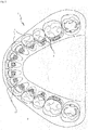
- the target set-up 3 of the Fig. 1 becomes a photo as follows (schematically in Fig. 2 ) created from the top view:
- the target set-up 3 is arranged centrally under a dome lighting, to achieve a uniform illumination of the same.
- a camera with an optic is aligned with the target set-up 3 to make a top view of the same.
- the camera is associated with a projector for a laser band 17, wherein the laser band 17 shows the focal plane of the optics of the camera.
- the vertical height of the target set-up 3 is adjusted by means of the laser band 17 so that the slot plane of the lingual brackets 5 of the target set-up 3 with the laser band 17 is at a vertical height.
- Fig. 2 schematically shows the photo of the target set-up 3 of Fig. 1 from the top view.
- the photo from the camera in the present case a digital camera
- the software serves i.wstl. to identify the location of the individual slots and to determine and then output.
- the procedure is as follows: In the software, the patient is first created with his patient-specific data, such as name and date of birth. Then it is specified whether the photo of a target set-up of a mandible or an upper jaw is to be processed. In the present case, it is stated that the photo of a target set-up 3 of a lower jaw is to be processed, and then specifies the location of the photo on the computer, after which the photo is loaded into the software.
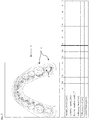
- Fig. 3 The screen is divided into two parts: In the upper half is the recording of the Fig. 2 shown (a 2dim Figure 9 of the target set-up with brackets in plan view). In the lower half there is a matrix in which one cleft is provided for each tooth of the lower jaw (from 47 to 41 and 31 to 37). In another column (in Fig. 3 on the left) individual parameters are listed line by line for each of these teeth, for each of which values can be entered for each tooth, as described below.
- the software now knows for which tooth the position of the slot of the brackets arranged on the tooth is to be identified.
- brackets from different manufacturers are deposited with their respective slot dimensions for each tooth and the software next asks the user which bracket of which company is located on the tooth, first by the manufacturer and then the bracket model by the user is queried. After the user of the software has announced which bracketing type from which manufacturer is located on the tooth, this step is completed. The software now knows which bracket with which slot dimensions is assigned to the tooth.
- the base plumb body 5B generally reflects the inner contour of the slot 5S of the bracket 5 and is presently a rectangle.
- the two lines of the reticle 19 each extend parallel to a short or long side of the rectangular base slot body 5B and the center of the reticle 19 is in the center of gravity of the base slot body 5B.
- the reticle 19 serves as an orientation aid to suitably position the base plumb body 5B in the slot 5S of the bracket 5 of the tooth 47 in a next step, ie to bring the base plumb body 5B into coincidence with the inner contour of the slot 5S of the bracket 5 in FIG the photo.
- the base slot body 5S is moved and rotated on the photo by mouse until the base slot body 5S coincides with the inner contour of the slot 5S in the photograph, such as in FIG Fig. 4 for the teeth 42 and 43 shown.
- the scale of imaging it in the photo is known and the base lot 5B in the software is tuned to that scale, thereby covering the base lot 5S and slot 5S in the photo.
- the position of the slot 5S is defined by means of the base slot body 5B for the bracket 5 of the tooth 47 and the associated data are automatically stored in the software.
- the data stored in the software comprises at least: tooth 47 and position and dimension of the slot 5S.
- the brackettype and the bracket manufacturer can also be saved.
- the slot can be rotated around its mid-point in the mesial or distal direction, with the desired angle in [°] to be entered, which is additionally desired.
- the desired value in mm can be entered into the column 47 in the line "Sliding path mesial" (fifth line) which is additionally desired.
- the software now writes all the data to a file in a next step.
- the file thus contains at least for each tooth to be treated: number of the tooth, the position and dimension of the slot 5S of the associated bracket 5, including the correction values made.
- other data such as, for example, the name of the patient, the Brackettyp and the bracket manufacturer can be stored with.
- a baking mold 11 (in the present case an aluminum plate) for the orthodontic wire 1 is created as follows: An aluminum plate measuring 79.5mm x 79.5mm x 2.5mm is placed in a CNC milling machine and fixed there. The aluminum plate has six flat surfaces.
- the o.g. File (with the data on the location, etc. of the slots) loaded.
- the sheet shape is milled into the aluminum plate, s. Fig. 5a showing a development of the bow shape.
- the milling head 21 does not milled the arch form at a height in the aluminum plate, but leaves areas corresponding to the slots and in which the orthodontic wire 1 must be held during baking, the so-called Drahtfixierabroughen 13.
- Die Fig. 5a shows accordingly several open spaces 15 and between the open spaces 15 elevated areas.
- the milling head 21 After the milling head 21 has milled the arcuate shape in the aluminum plate, it is automatically exchanged for one with a smaller diameter, whose diameter is slightly larger than that of the orthodontic wire 1.
- This milling head mills in the elevated areas formed between two free spaces a bottom 13 B, whereby Drahtfixierabroughe 13 are formed between the free spaces 15 in which the orthodontic wire 1 is held during baking thereof.
- the bottoms 13B of the wire fixing portions 13 and the bottoms 15B of the clearances 15 are then at a height such as Fig. 5b shows.
- the aluminum plate now has Drahtfixierabitese 13, of which the orthodontic wire 1 can be held, and free spaces 15, within which the orthodontic wire 1 can not be maintained on.
- the Drahtfixierabitese 13 correspond to the later slots 5S of the brackets.
- the aluminum plate thus forms the baking mold 11 for the orthodontic wire 1.
- Fig. 6 the finished baking mold is shown in plan view with their Drahtfixierabitesen 13 and their free spaces 15. Further, in the baking mold 11 is still the date of creation of the baking mold and the name and the first name of the patient and a case number milled, the latter still includes the indication UK, to indicate that it is the lower jaw model of the patient.
- the orthodontic wire 1 is inserted into the baking mold 11 by hand, i. the orthodontic wire 1 is inserted into the Drahtfixierabête 13 and then rests flat on the floors 13B and 15B.
- Fig. 7 shows the baking tin of the Fig. 6 , in which an orthodontic wire 1 is additionally inserted.
- the distal, after the last Drahtfixierabrough 13 projecting wire sections (in Fig. 7 below) can be shortened by the practitioner as needed.
- the orthodontic wire 1 thus arranged in the baking mold 11 is baked in an oven in the baking dish 11, whereby the orthodontic wire 1 is guided to this geometry, i. the desired target geometry is programmed. Now, the orthodontic wire 1 can be inserted into an orthodontic appliance of a patient.
- orthodontic appliance is understood to mean the arrangement of lingual or buccal brackets on a patient's orthodontically treated teeth.
- the target geometry is the geometry of the orthodontic wire, in which the treating orthodontist wants to have the orthodontic wire so that it causes the desired movement of the teeth to be treated in the state used in the orthodontic appliance.
- lingual brackets are preferably arranged on the teeth to be treated.
- buccal brackets can be placed on the teeth.
Landscapes
- Health & Medical Sciences (AREA)
- Life Sciences & Earth Sciences (AREA)
- Oral & Maxillofacial Surgery (AREA)
- Dentistry (AREA)
- Epidemiology (AREA)
- Animal Behavior & Ethology (AREA)
- General Health & Medical Sciences (AREA)
- Public Health (AREA)
- Veterinary Medicine (AREA)
- General Engineering & Computer Science (AREA)
- Engineering & Computer Science (AREA)
- Dental Tools And Instruments Or Auxiliary Dental Instruments (AREA)
- Dental Prosthetics (AREA)
Abstract
Description
- Die Erfindung betrifft ein Verfahren zum Verformen eines kieferorthopädischen Drahtes aus einem Formgedächtnismaterial und einen zugehörigen Draht. Weiter betrifft die Erfindung ein Verfahren zur Herstellung eines kieferorthopädischen Drahtes mittels des Verfahrens.
- Für die kieferorthopädische Behandlung von Patienten mit festsitzenden Klammern werden Brackets auf die zu behandelnden Zähne des Patienten geklebt und durch einen kieferorthopädischen Draht miteinander verbunden. Die Brackets weisen ein Pad zur Verbindung mit dem Zahn und einen Bracketbody auf, der den Drahtbogen aufnimmt.
- Zu Beginn einer kieferorthopädischen Behandlung werden häufig kieferorthopädische Drähte aus einem Formgedächtnismaterial in die Brackets eingesetzt, um eine "grobe" Ausrichtung der Zähne zu erreichen. Erst gegen Ende der kieferorthopädischen Behandlung werden bspw. Stahldrähte verwendet, um die Zähne möglichst genau in eine definierte Position zu bewegen.
- Damit die kieferorthopädischen Drähte eine gewünschte Kraft auf die Brackets und somit die Zähne übertragen, müssen sie eine bestimmte Geometrie (Zielgeometrie) aufweisen.
Es ist bekannt, kieferorthopädische Drähte aus Stahl mit Hilfe von Zangen in eine gewünschte Zielgeometrie zu überführen. - Dies funktioniert bei kieferorthopädischen Drähten aus einem Formgedächtnismaterial nicht, da sie kein herkömmliches Elastizitätsverhalten bei Verformung aufweisen.
- Zu den wichtigsten Formgedächtnismaterialien zählen Cu-Zn-X (X: Si, Sn, Al)- Legierungen und die intermetallische NiTi-Legierung (Nickelgehalt von ca. 55 Gew.-%), wobei die NiTi-Legierung aufgrund günstigerer Eigenschaften eine größere technologische Bedeutung erlangen konnte. Der Formgedächtnis-Effekt beruht auf einer thermoelastischen Martensitumwandlung, einer reversiblen, durch Scherung der Gitterebenen bedingten Phasenumwandlung. Die Abkühlung der Hochtemperatur-Phase, genannt Austenit, unter die legierungsspezifische Martensitstarttemperatur führt zu der Phasenumwandlung ohne Gestaltänderung und ohne irreversible plastische Verformung, wie es bei Stählen der Fall ist. Formgedächtnislegierungen lassen sich im martensitischen Zustand leicht verformen; die reversible Verformung kann bis zu 8% bei NiTi betragen. Diese Verformung ist bleibend, solange sich die Legierung im martensitischen Zustand befindet. Die Erwärmung auf eine Temperatur oberhalb der legierungsspezifischen Austenitstarttemperatur führt dann zur Rückstellung der ursprünglichen Gestalt.
- Die
DE 195 40 755 C2 beschreibt die gattungsgemäße Herstellung eines Bogendrahts aus Formgedächtnismaterial durch Eingipsen von Übertragungselementen, die in Slots von Brackets auf einem Modell einer Zielkonfiguration eingefügt sind, Lösen der Übertragungselemente von den Slots, Ersetzen von Abschnitten der Übertragungselemente durch Draht-Aufnahmevorrichtungen und Anordnen eines Drahtbogens in diese mit anschließendem Erwärmen zur dauerhaften Verformung. - Um einen kieferorthopädischen Draht aus einem Formgedächtnismaterial in eine Zielgeometrie zu überführen, wird dieser in einer speziellen Backform in die gewünschte Zielgeometrie gebracht und dann auf eine für das Formgedächtnismaterial spezifische Sprungtemperatur erhitzt. Anschließend wird der kieferorthopädische Draht wieder abgekühlt und in eine kieferorthopädische Apparatur eines Patienten, bspw. festsitzende Lingual- oder Bukkalbrackets, unter Verformung eingesetzt. In dem Mund des Patienten wird der kieferorthopädische Draht wieder erwärmt und erinnert sich an seine Zielgeometrie, in die er sich dann zurückverformen will. Während dieser Verformung übt der kieferorthopädische Draht eine Kraft auf die Brackets aus, wodurch die zugehörigen Zähne bewegt werden.
- Ein Nachteil bei der Verformung eines kieferorthopädischen Drahtes aus einem Formgedächtnismaterial in eine Zielgeometrie ist, dass das Verfahren sehr aufwändig und somit kostenintensiv ist.
- Die
DE 698 15 155 T2 beschreibt die Berechnung von Kräften, die von einem Bogendraht ausgeübt werden sollen, in einem virtuellen Modell. - Die Aufgabe der vorliegenden Erfindung liegt darin, ein alternatives Verfahren zur Herstellung eines kieferorthopädischen Drahts aus Formgedächtnismaterial in einer Zielgeometrie bereitzustellen, insbesondere ein einfacheres und kostengünstigeres Verfahren anzugeben, das zu einem kieferorthopädischen Draht aus einem Formgedächtnismaterial in einer Zielgeometrie führt.
- Die Aufgabe wird erfindungsgemäß durch ein Verfahren mit den Merkmalen des Anspruchs 1 gelöst, das zu einem zugehörigen kieferorthopädischen Draht gemäß seinem unabhängigen Anspruch führt.
- Im Schritt 1a) wird vorteilhaft ein Ziel-Set-Up aus Gips oder ein virtuelles Ziel-Set-Up erstellt.
- Im Schritt 1b) werden bevorzugt Lingualbrackets auf den zu behandelnden Zähnen des Ziel-Set-Ups angeordnet.
- Mit Vorteil wird im Schritt 1c) ein zweidimensionales Foto angefertigt, insbesondere unter Verwendung einer Kamera mit einer Optik.
- Bevorzugt wird für den Schritt 1c) ein Lichtband in das Ziel-Set-Up projiziert, das die Brennebene der Optik für die Anfertigung des Fotos zeigt, und das Lichtband wird weiter bevorzugt in die Slotebene projiziert, wodurch die Slots scharf in dem Foto dargestellt werden.
- Vorteilhaft wird im Schritt 1c) ein digitales Foto angefertigt.
- Mit Vorteil wird im Schritt 1d) ein digitales Foto oder ein Scan eines analogen Fotos in die Datenverarbeitungsanlage geladen.
- Bevorzugt wird als Datenverarbeitungsanlage ein Computer, insbesondere ein Desktop PC, verwendet.
- Das Identifizieren im Schritt 1e) erfolgt vorteilhaft von Hand oder automatisch, insbesondere mit Hilfe von Morphingalgorithmen.
- Mit Vorteil kann nach dem Identifizieren im Schritt 1e) die Lage mindestens eines Slots in der Okklusionsebene von Hand verändert werden, insbesondere nach mesial, distal, lingual oder bukkal oder Kombinationen davon, insbesondere Rotationen.
- Bevorzugt kann nach dem Identifizieren im Schritt 1e) die Länge mindestens eines Slots mesial und/oder distal erhöht oder verringert werden.
- Vorteilhaft ist das Exportieren im Schritt 1f) das Schreiben der Daten in eine Computerdatei.
- Mit Vorteil wird im Schritt 1g) eine Backform aus einer Metallplatte, insbesondere aus Stahl oder Aluminium, erstellt.
- Bevorzugt werden im Schritt 1g) die Drahtfixierabschnitte für den Draht in die Metallplatte bzw. in den Metallstreifen gefräst und jeweils ein Freiraum für den Draht zwischen benachbarte Drahtfixierabschnitte gefräst, in dem der Draht nicht gehalten wird.
- Vorteilhaft werden die Böden der Drahtfixierabschnitte und die Böden der Freiräume auf dieselbe Höhe gefräst, wodurch der Draht eben in die Backform eingelegt werden kann.
- Bevorzugt wird der Draht im Schritt 1h) von Hand in die Backform eingesetzt.
- Weitere Merkmale, Einzelheiten und Vorzüge der Erfindung ergeben sich aus den Ansprüchen und der nachfolgenden Beschreibung bevorzugter Ausführungsformen sowie anhand der Zeichnungen. Es zeigen schematisch:
- Fig. 1
- eine perspektivische Ansicht eines Ziel-Set-Ups mit Brackets,
- Fig. 2
- eine Draufsicht auf das Ziel-Set-Up der
Fig. 1 , - Fig. 3
- einen Screenshot einer Software zur Verarbeitung der Draufsicht der
Fig.2 , - Fig. 4
- einen vergrößerten Ausschnitt der
Fig. 3 , wobei zusätzlich Orientierungshilfen zur Identifizierung der Slots der Brackets dargestellt sind, - Fig. 5a
- eine schematische Querschnittsansicht einer Backform in einer Abwicklung entlang einer Bogenlinie und einen Fräskopf, wobei Freiräume für den kieferorthopädischen Draht in die Backform gefräst sind,
- Fig. 5b
- die Ansicht von
Fig. 5a ), wobei jedoch Drahtfixierabschnitte zwischen den Freiräumen gefräst sind, - Fig. 6
- eine Draufsicht auf eine fertige Backform, und
- Fig. 7
- die Backform der
Fig. 6 , in die ein kieferorthopädischer Draht eingelegt ist. - Von einem Patienten wird ein Gipsabdruck seines Unterkiefers erstellt, der kieferorthopädisch behandelt werden soll. Der Gipsabdruck wird zersägt, wobei die Zähne separiert werden. Anschließend werden die Zähne in einem Ziel-Set-Up 3, s.
Fig. 1 , angeordnet, das das gewünschte Behandlungsergebnis am Ende der Behandlung zeigen soll. In dem Ziel-Set-Up 3 derFig. 1 sind auf die Zähne 7 Lingualbrackets 5 geklebt. Am Ende der kieferorthopädischen Behandlung sollten alle Slots 5S der Lingualbrackets 5 i.wstl. in einer Ebene, der sog. Slotebene, liegen, wie inFig. 1 gezeigt. - Von dem Ziel-Set-Up 3 der
Fig. 1 wird wie folgt ein Foto (schematisch inFig. 2 ) aus der Draufsicht erstellt: Das Ziel-Set-Up 3 wird zentrisch unter einer Dombeleuchtung angeordnet, um eine gleichmäßige Ausleuchtung desselben zu erreichen. Eine Kamera mit einer Optik wird auf das Ziel-Set-Up 3 ausgerichtet, um aus der Draufsicht ein Foto desselben zu machen. - Der Kamera ist ein Projektor für ein Laserband 17 zugeordnet, wobei das Laserband 17 die Brennebene der Optik der Kamera zeigt. Die vertikale Höhe des Ziel-Set-Ups 3 wird mit Hilfe des Laserbandes 17 so eingestellt, dass die Slotebene der Lingualbrackets 5 des Ziel-Set-Ups 3 mit dem Laserband 17 auf einer vertikalen Höhe ist.
- Sobald die Optik der Kamera scharf auf die Slotebene der Lingualbrackets 5 des Ziel-Set-Ups 3 eingestellt ist, wird eine Aufnahme mit der Kamera erstellt.
Fig. 2 zeigt schematisch das Foto des Ziel-Set-Ups 3 derFig. 1 aus der Draufsicht. - In einem nächsten Schritt wird das Foto aus der Kamera, vorliegend eine Digitalkamera, in einen Computer übertragen und dort mit Hilfe einer selbst erstellten Software am Bildschirm wie folgt bearbeitet. Die Software dient i.wstl. dazu, die Lage der einzelnen Slots zu identifizieren und zu bestimmen und anschließend auszugeben. Dazu wird wie folgt vorgegangen:
In der Software wird zunächst der Patient mit seinen patientenspezifischen Daten, wie bspw. Name und Geburtsdatum, angelegt. Dann wird angegeben, ob das Foto eines Ziel-Set-Ups eines Unterkiefers oder eines Oberkiefers bearbeitet werden soll. Vorliegend wird angegeben, dass das Foto eines Ziel-Set-Ups 3 eines Unterkiefers bearbeitet werden soll und dann der Speicherort des Fotos auf dem Computer angegeben, woraufhin das Foto in die Software geladen wird. - Auf dem Bildschirm wird folgend die
Fig. 3 dargestellt. Der Bildschirm ist zweigeteilt: In der oberen Hälfte wird die Aufnahme derFig. 2 dargestellt (eine 2dim-Abbildung 9 des Ziel-Set-Ups mit Brackets in der Draufsicht). In der unteren Hälfte findet sich eine Matrix, in der für jeden Zahn des Unterkiefers eine Spalte vorgesehen ist (von 47 über 41 und 31 nach 37). In einer weiteren Spalte (inFig. 3 ganz links) sind zeilenweise einzelne Parameter für jeden dieser Zähne aufgeführt, für die für die einzelnen Zähne jeweils Werte eingegeben werden können, wie weiter unten beschrieben. - In einem nächsten Schritt klickt der Benutzer in der Matrix die Nummer des Zahns an, für den er den Slot des zugehörigen Brackets in dem Foto identifizieren möchte, d.h. der Benutzer klickt bspw. auf die Zahl "47" in der Matrix, um folgend für diesen Zahn die Lage des Slots zu bestimmen. Der Software ist nun bekannt, für welchen Zahn die Lage des Slots des auf dem Zahn angeordneten Brackets identifiziert werden soll.
- In der Software sind für jeden Zahn zugehörige Brackets von verschiedenen Herstellern mit ihren jeweiligen Slotabmessungen hinterlegt und die Software fragt in einem nächsten Schritt den Benutzer, welches Bracket von welcher Firma auf dem Zahn angeordnet ist, indem zunächst der Hersteller und dann das Bracketmodell von dem Benutzer abgefragt wird. Nachdem der Benutzer der Software bekannt gegeben hat, welcher Brackettyp von welchem Hersteller auf dem Zahn angeordnet ist, ist dieser Schritt beendet. Der Software ist nun bekannt, welches Bracket mit welchen Slotabmessungen dem Zahn zugeordnet ist.
- In einem nächsten Schritt klickt der Nutzer auf das Bracket des Zahns 47 in dem in
Fig. 3 oben dargestellten Foto, um die grobe Lage des Brackets der Software mitzuteilen. - Nun ist der Software bekannt, an welcher Stelle für welchen Zahn welches Bracket grob sitzt, und sie blendet an dieser Stelle einen Basisslotkörper 5B des entsprechenden Brackets 5 und ein zugehöriges Fadenkreuz 19 ein, s.
Fig. 4 . Der Basisslotkörper 5B gibt allgemein die innere Kontur des Slots 5S des Brackets 5 wider und ist vorliegend ein Rechteck. Die beiden Linien des Fadenkreuzes 19 verlaufen jeweils parallel zu einer kurzen bzw. langen Seite des rechteckigen Basisslotkörpers 5B und der Mittelpunkt des Fadenkreuzes 19 liegt im Schwerpunkt des Basisslotkörpers 5B. - Das Fadenkreuz 19 dient als Orientierungshilfe, um den Basisslotkörper 5B in dem Slot 5S des Brackets 5 des Zahns 47 in einem nächsten Schritt geeignet von Hand zu positionieren, d.h. den Basisslotkörper 5B in Deckung zu bringen mit der inneren Kontur des Slots 5S des Brackets 5 in dem Foto. Zu diesem Zweck wird der Basisslotkörper 5S auf dem Foto per Maus so lange verschoben und gedreht, bis der Basisslotkörper 5S zur Deckung kommt mit der inneren Kontur des Slots 5S in dem Foto, wie bspw. in
Fig. 4 für die Zähne 42 und 43 gezeigt. - Da das Foto des Ziel-Set-Ups 3 in einer definierten Brennebene der Optik der Kamera gemacht wird, ist der Maßstab der Abbildung desselben in dem Foto bekannt und der Basisslotkörper 5B in der Software ist auf diesen Maßstab abgestimmt, wodurch sich die Deckung von Basisslotkörper 5S und dem Slot 5S in dem Foto ergibt.
- Nun ist die Lage des Slots 5S mit Hilfe des Basisslotkörpers 5B für das Bracket 5 des Zahns 47 definiert und die zugehörigen Daten werden automatisch in der Software hinterlegt. Die in der Software hinterlegten Daten umfassen mindestens: Zahn 47 und Lage sowie Abmessung des Slots 5S. Wahlweise können auch der Brackettyp und der Brackethersteller mit abgespeichert werden.
- Die zuvor beschriebenen Schritte zur Identifikation der Lage des Slots 5S mit Hilfe des Basisslotkörpers 5B für den Zahn 47 werden folgend für jeden zu behandelnden Zahn des Unterkiefers wiederholt, wodurch die Lage eines jeden Slots 5S identifiziert ist.
- Ist die Identifikation der Lage für alle Slots 5S abgeschlossen, besteht mit Hilfe der in
Fig.3 unten dargestellten Matrix die Möglichkeit, für jeden Slot eines Brackets eines jeden Zahns den Wert von dort aufgeführten Parametern zu ändern:
Ist es in einem Beispiel erwünscht, die Position des Slots mesial bzw. distal zu verschieben, so kann in die zweite Zeile der inFig. 3 unten dargestellten Tabelle der gewünschte Wert in mm eingetragen werden, der zusätzlich gewünscht wird. - Analog kann mit einem Eintrag in der dritten Zeile der in
Fig. 3 unten dargestellten Tabelle die Slotposition bukkal bzw. lingual verschoben werden. - Durch einen Eintrag in die vierte Zeile der in
Fig. 3 unten dargestellten Tabelle kann der Slot um seinen Mittelpunkt in mesialer bzw. distaler Richtung gedreht werden, wobei dazu der gewünschte Winkel in [°] einzutragen ist, der zusätzlich gewünscht wird. - Ist es in einem weiteren Beispiel gewünscht, dass der Draht 1 in dem Slot 5S des Brackets 5 des Zahns 47 mesial mehr Slidingweg hat, so kann in die Spalte 47 in der Zeile "Slidingweg mesial" (fünfte Zeile) der gewünschte Wert in mm eingetragen werden, der zusätzlich gewünscht wird.
- Analog kann, wenn distal mehr Slidingweg gewünscht ist, der entsprechende Wert in die nächste (sechste) Zeile eingetragen werden, der zusätzlich gewünscht wird.
- Sind in die Matrix alle notwendigen Korrekturen eingetragen, so sind die Identifikation der Lage der Slots 5S und die notwendigen Korrekturen davon abgeschlossen. Auf Anforderung des Benutzers schreibt die Software nun in einem nächsten Schritt alle Daten in eine Datei. Die Datei enthält somit mindestens für jeden zu behandelnden Zahn: Nummer des Zahns, die Lage sowie Abmessung des Slots 5S des zugehörigen Brackets 5, einschließlich der vorgenommenen Korrekturwerte. Wahlweise können auch weitere Daten, wie bspw. der Name des Patienten, der Brackettyp und der Brackethersteller mit abgespeichert werden.
- Als nächstes wird mit Hilfe dieser Datei eine Backform 11 (vorliegend eine Aluminiumplatte) für den kieferorthopädischen Draht 1 wie folgt erstellt:
Eine Aluminiumplatte mit den Abmessungen 79,5mm x 79,5mm x 2,5mm wird in eine CNC-Fräsmaschine eingelegt und dort fixiert. Die Aluminiumplatte weist sechs ebene Oberflächen auf. - In die CNC-Fräsmaschine wird ferner die o.g. Datei (mit den Daten zur Lage usw. der Slots) geladen.
- Mit Hilfe eines zylindrischen Fräskopfes 21 mit einer Breite von 2mm wird in die Aluminiumplatte die Bogenform gefräst, s.
Fig. 5a , die eine Abwicklung der Bogenform zeigt. Der Fräskopf 21 fräst die Bogenform nicht auf einer Höhe in die Aluminiumplatte, sondern lässt Bereiche stehen, die den Slots entsprechen und in denen der kieferorthopädische Draht 1 während des Backens gehalten werden muss, den sog. Drahtfixierabschnitten 13. DieFig. 5a zeigt dementsprechend mehrere Freiräume 15 und zwischen den Freiräumen 15 erhöhte Bereiche. - Nachdem der Fräskopf 21 die Bogenform in die Aluminiumplatte gefräst hat, wird er automatisch gegen einen mit einem kleineren Durchmesser ausgetauscht, dessen Durchmesser etwas größer als der des kieferorthopädischen Drahtes 1 ist.
- Dieser Fräskopf fräst in die zwischen zwei Freiräumen gebildeten erhöhten Bereiche einen Boden 13B, wodurch Drahtfixierabschnitte 13 zwischen den Freiräumen 15 gebildet sind, in denen der kieferorthopädische Draht 1 während des Backens desselben gehalten wird.
- Die Böden 13B der Drahtfixierabschnitte 13 und die Böden 15B der Freiräume 15 liegen dann auf einer Höhe, wie die
Fig. 5b zeigt. - Die Aluminiumplatte weist nun Drahtfixierabschnitte 13, von denen der kieferorthopädische Draht 1 gehalten werden kann, und Freiräume 15, innerhalb derer der kieferorthopädische Draht 1 nicht gehalten werden kann, auf. Die Drahtfixierabschnitte 13 entsprechen den späteren Slots 5S der Brackets. Die Aluminiumplatte bildet auf diese Weise die Backform 11 für den kieferorthopädischen Draht 1. In
Fig. 6 ist die fertige Backform in der Draufsicht mit ihren Drahtfixierabschnitten 13 und ihren Freiräumen 15 gezeigt. Ferner ist in die Backform 11 noch das Erstellungsdatum der Backform sowie der Name und der Vorname des Patienten sowie eine Fallnummer gefräst, wobei letztere noch die Angabe UK umfasst, um anzuzeigen, dass es sich um das Unterkiefermodell des Patienten handelt. - Nachdem die Backform 11 erstellt ist, wird der kieferorthopädische Draht 1 in die Backform 11 von Hand eingelegt, d.h. der kieferorthopädische Draht 1 wird in die Drahtfixierabschnitte 13 eingelegt und liegt dann plan auf den Böden 13B und 15B auf.
-
Fig. 7 zeigt die Backform derFig. 6 , in die zusätzlich ein kieferorthopädischer Draht 1 eingelegt ist. Die distal, nach dem letzten Drahtfixierabschnitt 13 überstehenden Drahtabschnitte (inFig. 7 unten) können vom Behandler je nach Bedarf gekürzt werden. - In einem nächsten Schritt wird der auf diese Weise in der Backform 11 angeordnete kieferorthopädische Draht 1 in einem Backofen in der Backform 11 gebacken, wodurch der kieferorthopädische Draht 1 auf diese Geometrie, d.h. die gewünschte Zielgeometrie, programmiert wird. Nun kann der kieferorthopädische Draht 1 in eine kieferorthopädische Apparatur eines Patienten eingesetzt werden.
- Unter dem Begriff "kieferorthopädische Apparatur" ist im Rahmen der vorliegenden Anmeldung die Anordnung aus Lingual- oder Bukkalbrackets auf kieferorthopädisch zu behandelnden Zähnen eines Patienten zu verstehen.
- Die Zielgeometrie ist die Geometrie des kieferorthopädischen Drahtes, in der der behandelnde Kieferorthopäde den kieferorthopädischen Draht haben will, damit er im in der kieferorthopädischen Apparatur eingesetzten Zustand die gewünschte Bewegung der zu behandelnden Zähne bewirkt.
- Im Schritt 1b) werden bevorzugt Lingualbrackets auf den zu behandelnden Zähnen angeordnet. Alternativ können auch Bukkalbrackets auf den Zähnen angeordnet werden.
-
- 1
- kieferorthopädischer Draht
- 3
- patientenspezifisches Ziel-Set-Up eines Unterkiefers eines Patienten
- 5
- (Lingual-) Bracket
- 5B
- Basisslotkörper
- 5S
- Slot des Brackets
- 7
- Zahn
- 9
- 2dim-Abbildung des Ziel-Set-Ups mit Brackets in der Draufsicht
- 11
- Backform
- 13
- Drahtfixierabschnitt
- 13B
- Boden eines Drahtfixierabschnitts
- 15
- Freiraum
- 15B
- Boden eines Freiraums
- 17
- Laserband
- 19
- Fadenkreuz
- 21
- Fräskopf
Claims (17)
- Verfahren zum Verformen eines kieferorthopädischen Drahtes (1) aus einem Formgedächtnismaterial in eine Zielgeometrie zum passenden Einsetzen in eine patientenspezifische kieferorthopädische Apparatur mit folgenden Schritten:a. Erstellen eines patientenspezifischen Ziel-Set-Ups des Ober- oder Unterkiefers des Patienten,b. Anordnen von Brackets (5) auf zu behandelnden Zähnen im Ziel-Set-Up,c. Anfertigen einer 2dim-Abbildung des Ziel-Set-Ups mit Brackets (5) in der Draufsicht,d. Laden der Abbildung in eine Datenverarbeitungsanlage,e. Identifizieren der Lage der Slots (5S) der Brackets (5) in der Abbildung,f. Exportieren von Daten der Lage der Slots (5S) aus der Datenverarbeitungsanlage,g. Erstellen einer Backform (11) für den Formgedächtnisdraht, wobei mit Hilfe der Daten Drahtfixierabschnitte (13) in der Backform generiert werden, die den Draht in den zu den Slots (5S) korrespondierenden Bereichen während des Backens halten,h. Einsetzen des Drahtes in die Backform undi. Backen des Drahtes.
- Verfahren nach Anspruch 1, dadurch gekennzeichnet, dass im Schritt 1a) ein Ziel-Set-Up aus Gips oder ein virtuelles Ziel-Set-Up erstellt wird.
- Verfahren nach Anspruch 1 oder 2, dadurch gekennzeichnet, dass im Schritt 1b) Lingualbrackets auf den zu behandelnden Zähnen des Ziel-Set-Ups angeordnet werden.
- Verfahren nach einem der vorangehenden Ansprüche, dadurch gekennzeichnet, dass im Schritt 1c) ein zweidimensionales Foto angefertigt wird, insbesondere unter Verwendung einer Kamera mit einer Optik.
- Verfahren nach Anspruch 4, dadurch gekennzeichnet, dass für den Schritt 1c) ein Lichtband in das Ziel-Set-Up projiziert wird, das die Brennebene der Optik für die Anfertigung des Fotos zeigt, und das Lichtband in die Slotebene projiziert wird, wodurch die Slots (5S) scharf in der Abbildung dargestellt werden.
- Verfahren nach Anspruch 4 oder 5, dadurch gekennzeichnet, dass im Schritt 1c) als Abbildung ein digitales Foto angefertigt wird.
- Verfahren nach einem der vorangehenden Ansprüche, dadurch gekennzeichnet, dass im Schritt 1d) ein digitales Foto oder ein Scan eines analogen Fotos in die Datenverarbeitungsanlage geladen wird.
- Verfahren nach einem der vorangehenden Ansprüche, dadurch gekennzeichnet, dass als Datenverarbeitungsanlage ein Computer, insbesondere ein Desktop PC, verwendet wird.
- Verfahren nach einem der vorangehenden Ansprüche, dadurch gekennzeichnet, dass das Identifizieren im Schritt 1e) von Hand oder automatisch, insbesondere mit Hilfe von Morphingalgorithmen, erfolgt.
- Verfahren nach einem der vorangehenden Ansprüche, dadurch gekennzeichnet, dass nach dem Identifizieren im Schritt 1e) die Lage mindestens eines Slots (5S) in der Okklusionsebene von Hand verändert wird, insbesondere nach mesial, distal, lingual oder bukkal, per Rotation oder Kombinationen davon.
- Verfahren nach einem der vorangehenden Ansprüche, dadurch gekennzeichnet, dass nach dem Identifizieren im Schritt 1e) die Länge mindestens eines Slots mesial und/oder distal erhöht oder verringert wird.
- Verfahren nach einem der vorangehenden Ansprüche, dadurch gekennzeichnet, dass das Exportieren im Schritt 1f) das Schreiben der Daten in eine Computerdatei ist.
- Verfahren nach einem der vorangehenden Ansprüche, dadurch gekennzeichnet, dass im Schritt 1g) eine Backform aus einer Metallplatte, insbesondere aus Stahl oder Aluminium, erstellt wird.
- Verfahren nach Anspruch 13, dadurch gekennzeichnet, dass im Schritt 1g) die Drahtfixierabschnitte für den Draht in den Metallstreifen gefräst werden und jeweils ein Freiraum für den Draht zwischen benachbarte Drahtfixierabschnitte gefräst wird, in dem der Draht nicht gehalten wird.
- Verfahren nach Anspruch 14, dadurch gekennzeichnet, dass die Böden der Drahtfixierabschnitte und die Böden der Freiräume auf dieselbe Höhe gefräst werden, wodurch der Draht eben in die Backform eingelegt werden kann.
- Verfahren nach einem der vorangehenden Ansprüche, dadurch gekennzeichnet, dass der Draht im Schritt 1h) von Hand in die Backform eingesetzt wird.
- Kieferorthopädischer Draht aus einem Formgedächtnismaterial verformt in eine Zielgeometrie nach einem Verfahren nach einem der vorangehenden Ansprüche.
Applications Claiming Priority (3)
| Application Number | Priority Date | Filing Date | Title |
|---|---|---|---|
| DE102011081151A DE102011081151A1 (de) | 2011-08-17 | 2011-08-17 | Verfahren zum Verformen eines kieferorthopädischen Drahtes aus einem Formgedächtnismaterial und zugehöriger Draht |
| PCT/EP2012/065190 WO2013023935A1 (de) | 2011-08-17 | 2012-08-02 | Verfahren zum verformen eines kieferorthopädischen drahtes aus einem formgedächtnismaterial und zugehöriger draht |
| EP12745474.2A EP2744440B1 (de) | 2011-08-17 | 2012-08-02 | Verfahren zum verformen eines kieferorthopädischen drahtes aus einem formgedächtnismaterial |
Related Parent Applications (2)
| Application Number | Title | Priority Date | Filing Date |
|---|---|---|---|
| EP12745474.2A Division-Into EP2744440B1 (de) | 2011-08-17 | 2012-08-02 | Verfahren zum verformen eines kieferorthopädischen drahtes aus einem formgedächtnismaterial |
| EP12745474.2A Division EP2744440B1 (de) | 2011-08-17 | 2012-08-02 | Verfahren zum verformen eines kieferorthopädischen drahtes aus einem formgedächtnismaterial |
Publications (2)
| Publication Number | Publication Date |
|---|---|
| EP3488812A1 true EP3488812A1 (de) | 2019-05-29 |
| EP3488812B1 EP3488812B1 (de) | 2021-03-31 |
Family
ID=46640033
Family Applications (2)
| Application Number | Title | Priority Date | Filing Date |
|---|---|---|---|
| EP18211536.0A Active EP3488812B1 (de) | 2011-08-17 | 2012-08-02 | Verfahren zum verformen eines kieferorthopädischen drahtes aus einem formgedächtnismaterial und zugehöriger draht |
| EP12745474.2A Active EP2744440B1 (de) | 2011-08-17 | 2012-08-02 | Verfahren zum verformen eines kieferorthopädischen drahtes aus einem formgedächtnismaterial |
Family Applications After (1)
| Application Number | Title | Priority Date | Filing Date |
|---|---|---|---|
| EP12745474.2A Active EP2744440B1 (de) | 2011-08-17 | 2012-08-02 | Verfahren zum verformen eines kieferorthopädischen drahtes aus einem formgedächtnismaterial |
Country Status (7)
| Country | Link |
|---|---|
| US (1) | US9566133B2 (de) |
| EP (2) | EP3488812B1 (de) |
| JP (1) | JP6050353B2 (de) |
| DE (1) | DE102011081151A1 (de) |
| ES (1) | ES2728915T3 (de) |
| TR (1) | TR201907768T4 (de) |
| WO (1) | WO2013023935A1 (de) |
Families Citing this family (25)
| Publication number | Priority date | Publication date | Assignee | Title |
|---|---|---|---|---|
| ES2874777T3 (es) | 2012-10-30 | 2021-11-05 | Univ Southern California | Aparato de ortodoncia con arco de alambre encajado a presión, antideslizante |
| DE102013209735A1 (de) * | 2013-05-24 | 2014-11-27 | Dw Lingual Systems Gmbh | Verfahren zum Herstellen eines patientenspezifischen Ersatzbrackets für eine kieferorthopädische Behandlung sowie nach dem Verfahren hergestelltes Bracket |
| DE102015101689A1 (de) | 2015-02-05 | 2016-08-11 | Technische Universität Dresden | Schlaufe für einen kieferorthopädischen Lückenschluss |
| EP3267926A1 (de) * | 2015-03-13 | 2018-01-17 | 3M Innovative Properties Company | Orthodontisches gerät mit bogenelement |
| KR101643504B1 (ko) * | 2015-07-17 | 2016-07-27 | 이종호 | 맞춤형 치아교정 호선 제작키트 및 이를 이용한 치아교정 호선 제작방법 |
| KR101678312B1 (ko) * | 2015-08-26 | 2016-11-21 | 이종호 | 개인 맞춤형 치아교정용 각형 와이어 제조방법 |
| BR112018011378B1 (pt) * | 2015-12-06 | 2021-09-08 | Brius Technologies, Inc. | Aparelhos ortodônticos para reposicionamento de dentes |
| CN109195547B (zh) | 2016-04-18 | 2021-06-18 | 斯威夫特健康系统有限公司 | 具有非滑动的绑扎弓丝的牙齿正畸矫正器 |
| WO2018144634A1 (en) | 2017-01-31 | 2018-08-09 | Swift Health Systems Inc. | Hybrid orthodontic archwires |
| CN110740704B (zh) | 2017-04-21 | 2021-10-29 | 斯威夫特健康系统有限公司 | 间接粘接托盘、非滑动正畸矫正器和使用其的配准系统 |
| KR20190082452A (ko) * | 2018-01-02 | 2019-07-10 | 주식회사 링구얼라인 | 맞춤형 치아교정 3차원 아치 와이어 제작방법 |
| FR3080023B1 (fr) * | 2018-04-11 | 2021-10-22 | Orthomoov | Orthese dentaire, procedes de caracterisation et/ou de fabrication associes |
| US20200275996A1 (en) | 2019-03-01 | 2020-09-03 | Swift Health Systems Inc. | Indirect bonding trays with bite turbo and orthodontic auxiliary integration |
| WO2020223744A1 (en) | 2019-05-02 | 2020-11-05 | Brius Technologies, Inc. | Dental appliances and associated methods of manufacturing |
| US12053346B2 (en) | 2019-10-31 | 2024-08-06 | Swift Health Systems Inc. | Indirect orthodontic bonding systems and methods |
| CN111068310B (zh) * | 2019-11-21 | 2021-05-11 | 珠海剑心互动娱乐有限公司 | 一种实现游戏地图无缝加载的方法及系统 |
| CN116075279A (zh) | 2020-06-11 | 2023-05-05 | 斯威夫特健康系统公司 | 具有非滑动弓形件的正畸矫正器 |
| US12144700B2 (en) | 2020-11-05 | 2024-11-19 | Brius Technologies, Inc. | Dental appliances and associated systems and methods |
| DE102020214587A1 (de) | 2020-11-19 | 2022-05-19 | Dirk Wiechmann | Verfahren zum Programmieren eines kieferorthopädischen Bauteils aus einem Formgedächtnismaterial |
| WO2022192409A2 (en) | 2021-03-12 | 2022-09-15 | Swift Health Systems Inc. | Indirect orthodontic bonding systems and methods |
| US11504212B2 (en) | 2021-03-25 | 2022-11-22 | Brius Technologies, Inc. | Orthodontic treatment and associated devices, systems, and methods |
| EP4395687A4 (de) | 2021-09-03 | 2025-07-02 | Swift Health Systems Inc | Orthodontische vorrichtung mit nichtgleitender fussgewölbeform |
| WO2023033870A1 (en) | 2021-09-03 | 2023-03-09 | Swift Health Systems Inc. | Method of administering adhesive to bond orthodontic brackets |
| USD1043994S1 (en) | 2022-01-06 | 2024-09-24 | Swift Health Systems Inc. | Archwire |
| KR102765154B1 (ko) * | 2022-05-23 | 2025-02-06 | 정연호 | 치아교정을 위한 와이어 벤딩 경로 생성 방법 및 이를 수행하기 위한 장치 |
Citations (4)
| Publication number | Priority date | Publication date | Assignee | Title |
|---|---|---|---|---|
| US5456600A (en) * | 1992-11-09 | 1995-10-10 | Ormco Corporation | Coordinated orthodontic archwires and method of making same |
| US20040083611A1 (en) * | 2002-11-06 | 2004-05-06 | Ruedger Rubbert | Method and system for customizing an orthodontic archwire |
| DE102006048063A1 (de) * | 2006-10-11 | 2008-04-17 | Heßling, Ralf, Dr. | Vorrichtung zur Regulierung von Zahnfehlstellungen mit orthodontischen Bögen und Verfahren zu deren Herstellung |
| US20080254403A1 (en) * | 2007-04-10 | 2008-10-16 | Jack Keith Hilliard | System for cnc-machining fixtures to set orthodontic archwires |
Family Cites Families (9)
| Publication number | Priority date | Publication date | Assignee | Title |
|---|---|---|---|---|
| US4037324A (en) * | 1972-06-02 | 1977-07-26 | The University Of Iowa Research Foundation | Method and system for orthodontic moving of teeth |
| DE69116751T2 (de) * | 1990-06-07 | 1996-07-11 | Tokin Corp | Orthodontische Vorrichtung mit kontrollierbarer Korrekturkraft |
| DE69327661T2 (de) * | 1992-11-09 | 2000-07-20 | Ormco Corp., Glendora | Verfahren und vorrichtung zum herstellen von individuell angepasstenorthodontischen einrichtungen |
| DE19540755C2 (de) * | 1995-11-02 | 1997-08-14 | Fischer Brandies Helge Prof Me | Verfahren zum Herstellen eines zur Korrektur einer Zahnfehlstellung dienenden Drahtbogens |
| IL122807A0 (en) * | 1997-12-30 | 1998-08-16 | Cadent Ltd | Virtual orthodontic treatment |
| US6413083B1 (en) * | 1999-11-09 | 2002-07-02 | Dentsply Research & Development Corp. | Computerized system and method for correcting tooth-size discrepancies |
| EP2258303B1 (de) | 2000-04-19 | 2013-09-18 | OraMetrix, Inc. | System zur Erstellung eines individuellen virtuellen dreidimensionalen Modells eines Zahnes |
| US6733289B2 (en) * | 2001-07-30 | 2004-05-11 | 3M Innovative Properties Company | Method and apparatus for selecting a prescription for an orthodontic brace |
| JP4191994B2 (ja) * | 2002-12-16 | 2008-12-03 | 株式会社松風 | 咬合面形状計測及び運動再現装置 |
-
2011
- 2011-08-17 DE DE102011081151A patent/DE102011081151A1/de active Pending
-
2012
- 2012-08-02 TR TR2019/07768T patent/TR201907768T4/tr unknown
- 2012-08-02 ES ES12745474T patent/ES2728915T3/es active Active
- 2012-08-02 EP EP18211536.0A patent/EP3488812B1/de active Active
- 2012-08-02 WO PCT/EP2012/065190 patent/WO2013023935A1/de not_active Ceased
- 2012-08-02 JP JP2014525394A patent/JP6050353B2/ja active Active
- 2012-08-02 US US14/238,362 patent/US9566133B2/en not_active Expired - Fee Related
- 2012-08-02 EP EP12745474.2A patent/EP2744440B1/de active Active
Patent Citations (4)
| Publication number | Priority date | Publication date | Assignee | Title |
|---|---|---|---|---|
| US5456600A (en) * | 1992-11-09 | 1995-10-10 | Ormco Corporation | Coordinated orthodontic archwires and method of making same |
| US20040083611A1 (en) * | 2002-11-06 | 2004-05-06 | Ruedger Rubbert | Method and system for customizing an orthodontic archwire |
| DE102006048063A1 (de) * | 2006-10-11 | 2008-04-17 | Heßling, Ralf, Dr. | Vorrichtung zur Regulierung von Zahnfehlstellungen mit orthodontischen Bögen und Verfahren zu deren Herstellung |
| US20080254403A1 (en) * | 2007-04-10 | 2008-10-16 | Jack Keith Hilliard | System for cnc-machining fixtures to set orthodontic archwires |
Also Published As
| Publication number | Publication date |
|---|---|
| US20140234794A1 (en) | 2014-08-21 |
| ES2728915T3 (es) | 2019-10-29 |
| EP2744440B1 (de) | 2019-03-06 |
| US9566133B2 (en) | 2017-02-14 |
| RU2014109929A (ru) | 2015-09-27 |
| TR201907768T4 (tr) | 2019-06-21 |
| EP3488812B1 (de) | 2021-03-31 |
| EP2744440A1 (de) | 2014-06-25 |
| JP2014521480A (ja) | 2014-08-28 |
| JP6050353B2 (ja) | 2016-12-21 |
| DE102011081151A1 (de) | 2013-02-21 |
| WO2013023935A1 (de) | 2013-02-21 |
Similar Documents
| Publication | Publication Date | Title |
|---|---|---|
| EP2744440B1 (de) | Verfahren zum verformen eines kieferorthopädischen drahtes aus einem formgedächtnismaterial | |
| DE60207418T2 (de) | Verfahren und vorrichtung zum auswählen einer verordnung für eine orthodontische apparatur | |
| DE60320498T2 (de) | Vorrichtung zur orthodonischen Korrektur | |
| EP3188685B1 (de) | Verfahren zur herstellung eines positionierungstrays und die vorrichtung dazu | |
| EP3454774B1 (de) | Vorrichtung zur korrektur von zahnfehlstellungen sowie verfahren zur herstellung eines bogenelements für eine solche vorrichtung | |
| EP2361585B1 (de) | Bracketsystem und Verfahren zur Planung und Herstellung eines Bracketsystems zur Korrektur von Zahnfehlstellungen | |
| EP2672918B1 (de) | Verfahren zur herstellung eines patientenspezifischen bracketkörpers und zugehöriger bracketkörper | |
| DE112010002713T5 (de) | Kierferorthopädischer Bogendraht geringer Kraft mit Eingreifblöcken für verbesserte Behandlung | |
| EP1601303B1 (de) | Vorrichtung zur auswahl eines bereichs eines in einer 3d-darstellung dargestellten dentalen restaurationskörpers und verfahren dazu | |
| DE102013010186A1 (de) | Anordnung, Vorrichtung und Verfahren zum Herstellen eines orthodontischen Apparats und Vorrichtung zum indirekten Kleben eines orthodontischen Apparats | |
| DE102012224328A1 (de) | Führungselement für einen Zahn | |
| DE102007033989A1 (de) | System und Verfahren für die automatische Konstruktion kieferorthopädischer Bezugspunkte | |
| DE102018210258A1 (de) | Verfahren zur Konstruktion eines dentalen Bauteils | |
| WO2016071508A1 (de) | Verfahren zur herstellung einer vorgespannten zahn-repositionierungseinrichtung | |
| WO2012107501A1 (de) | Verfahren zur herstellung mindestens eines patientenspezifischen, modular aufgebauten brackets und zugehöriges bracket | |
| WO2012107503A1 (de) | Verfahren zur herstellung einer patientenspezifischen auflage und zugehörige auflage | |
| DE102019003296B4 (de) | Verfahren zur Herstellung einer Dentalschiene und Verfahren zur Herstellung eines Dentalschienensystems | |
| DE10300010B4 (de) | Brackets sowie ein Verfahren zu ihrer Herstellung | |
| EP2957254A1 (de) | Verfahren zur Herstellung kieferorthopädischer Zahnschienen | |
| EP2950742B1 (de) | Verfahren zum herstellen von herausnehmbaren zahnmedizinischen apparaturen | |
| DE102009043048B4 (de) | Gebisshalterung, Anordnung von Einzelzahnmodellen und Gebisshalterung und Verfahren zur vereinfachten Übertragung einer virtuellen Zahnstellung in ein reales Gebissmodell | |
| EP4008290B1 (de) | Verfahren zum programmieren eines kieferorthopädischen bauteils aus einem formgedächtnismaterial | |
| DE102013207781A1 (de) | Segmentiertes Dentalmodell | |
| Pancherz | Extraktion eines Incisivus im Unterkiefer bei der Herbst-Behandlung. | |
| WO2025228531A1 (de) | Verfahren und vorrichtung zur modellierung oder konstruktion einer dentalprothese |
Legal Events
| Date | Code | Title | Description |
|---|---|---|---|
| PUAI | Public reference made under article 153(3) epc to a published international application that has entered the european phase |
Free format text: ORIGINAL CODE: 0009012 |
|
| STAA | Information on the status of an ep patent application or granted ep patent |
Free format text: STATUS: THE APPLICATION HAS BEEN PUBLISHED |
|
| AC | Divisional application: reference to earlier application |
Ref document number: 2744440 Country of ref document: EP Kind code of ref document: P |
|
| AK | Designated contracting states |
Kind code of ref document: A1 Designated state(s): AL AT BE BG CH CY CZ DE DK EE ES FI FR GB GR HR HU IE IS IT LI LT LU LV MC MK MT NL NO PL PT RO RS SE SI SK SM TR |
|
| STAA | Information on the status of an ep patent application or granted ep patent |
Free format text: STATUS: REQUEST FOR EXAMINATION WAS MADE |
|
| RAP1 | Party data changed (applicant data changed or rights of an application transferred) |
Owner name: 3M INNOVATIVE PROPERTIES COMPANY |
|
| 17P | Request for examination filed |
Effective date: 20191128 |
|
| RBV | Designated contracting states (corrected) |
Designated state(s): AL AT BE BG CH CY CZ DE DK EE ES FI FR GB GR HR HU IE IS IT LI LT LU LV MC MK MT NL NO PL PT RO RS SE SI SK SM TR |
|
| STAA | Information on the status of an ep patent application or granted ep patent |
Free format text: STATUS: EXAMINATION IS IN PROGRESS |
|
| 17Q | First examination report despatched |
Effective date: 20200520 |
|
| GRAP | Despatch of communication of intention to grant a patent |
Free format text: ORIGINAL CODE: EPIDOSNIGR1 |
|
| STAA | Information on the status of an ep patent application or granted ep patent |
Free format text: STATUS: GRANT OF PATENT IS INTENDED |
|
| INTG | Intention to grant announced |
Effective date: 20201207 |
|
| GRAS | Grant fee paid |
Free format text: ORIGINAL CODE: EPIDOSNIGR3 |
|
| GRAA | (expected) grant |
Free format text: ORIGINAL CODE: 0009210 |
|
| STAA | Information on the status of an ep patent application or granted ep patent |
Free format text: STATUS: THE PATENT HAS BEEN GRANTED |
|
| AC | Divisional application: reference to earlier application |
Ref document number: 2744440 Country of ref document: EP Kind code of ref document: P |
|
| AK | Designated contracting states |
Kind code of ref document: B1 Designated state(s): AL AT BE BG CH CY CZ DE DK EE ES FI FR GB GR HR HU IE IS IT LI LT LU LV MC MK MT NL NO PL PT RO RS SE SI SK SM TR |
|
| REG | Reference to a national code |
Ref country code: GB Ref legal event code: FG4D Free format text: NOT ENGLISH Ref country code: CH Ref legal event code: EP |
|
| REG | Reference to a national code |
Ref country code: AT Ref legal event code: REF Ref document number: 1376087 Country of ref document: AT Kind code of ref document: T Effective date: 20210415 |
|
| REG | Reference to a national code |
Ref country code: DE Ref legal event code: R096 Ref document number: 502012016707 Country of ref document: DE |
|
| REG | Reference to a national code |
Ref country code: IE Ref legal event code: FG4D Free format text: LANGUAGE OF EP DOCUMENT: GERMAN |
|
| REG | Reference to a national code |
Ref country code: LT Ref legal event code: MG9D |
|
| PG25 | Lapsed in a contracting state [announced via postgrant information from national office to epo] |
Ref country code: NO Free format text: LAPSE BECAUSE OF FAILURE TO SUBMIT A TRANSLATION OF THE DESCRIPTION OR TO PAY THE FEE WITHIN THE PRESCRIBED TIME-LIMIT Effective date: 20210630 Ref country code: HR Free format text: LAPSE BECAUSE OF FAILURE TO SUBMIT A TRANSLATION OF THE DESCRIPTION OR TO PAY THE FEE WITHIN THE PRESCRIBED TIME-LIMIT Effective date: 20210331 Ref country code: FI Free format text: LAPSE BECAUSE OF FAILURE TO SUBMIT A TRANSLATION OF THE DESCRIPTION OR TO PAY THE FEE WITHIN THE PRESCRIBED TIME-LIMIT Effective date: 20210331 Ref country code: BG Free format text: LAPSE BECAUSE OF FAILURE TO SUBMIT A TRANSLATION OF THE DESCRIPTION OR TO PAY THE FEE WITHIN THE PRESCRIBED TIME-LIMIT Effective date: 20210630 |
|
| PG25 | Lapsed in a contracting state [announced via postgrant information from national office to epo] |
Ref country code: LV Free format text: LAPSE BECAUSE OF FAILURE TO SUBMIT A TRANSLATION OF THE DESCRIPTION OR TO PAY THE FEE WITHIN THE PRESCRIBED TIME-LIMIT Effective date: 20210331 Ref country code: RS Free format text: LAPSE BECAUSE OF FAILURE TO SUBMIT A TRANSLATION OF THE DESCRIPTION OR TO PAY THE FEE WITHIN THE PRESCRIBED TIME-LIMIT Effective date: 20210331 Ref country code: SE Free format text: LAPSE BECAUSE OF FAILURE TO SUBMIT A TRANSLATION OF THE DESCRIPTION OR TO PAY THE FEE WITHIN THE PRESCRIBED TIME-LIMIT Effective date: 20210331 |
|
| REG | Reference to a national code |
Ref country code: NL Ref legal event code: MP Effective date: 20210331 |
|
| PG25 | Lapsed in a contracting state [announced via postgrant information from national office to epo] |
Ref country code: SM Free format text: LAPSE BECAUSE OF FAILURE TO SUBMIT A TRANSLATION OF THE DESCRIPTION OR TO PAY THE FEE WITHIN THE PRESCRIBED TIME-LIMIT Effective date: 20210331 Ref country code: NL Free format text: LAPSE BECAUSE OF FAILURE TO SUBMIT A TRANSLATION OF THE DESCRIPTION OR TO PAY THE FEE WITHIN THE PRESCRIBED TIME-LIMIT Effective date: 20210331 Ref country code: CZ Free format text: LAPSE BECAUSE OF FAILURE TO SUBMIT A TRANSLATION OF THE DESCRIPTION OR TO PAY THE FEE WITHIN THE PRESCRIBED TIME-LIMIT Effective date: 20210331 Ref country code: EE Free format text: LAPSE BECAUSE OF FAILURE TO SUBMIT A TRANSLATION OF THE DESCRIPTION OR TO PAY THE FEE WITHIN THE PRESCRIBED TIME-LIMIT Effective date: 20210331 Ref country code: LT Free format text: LAPSE BECAUSE OF FAILURE TO SUBMIT A TRANSLATION OF THE DESCRIPTION OR TO PAY THE FEE WITHIN THE PRESCRIBED TIME-LIMIT Effective date: 20210331 |
|
| PG25 | Lapsed in a contracting state [announced via postgrant information from national office to epo] |
Ref country code: IS Free format text: LAPSE BECAUSE OF FAILURE TO SUBMIT A TRANSLATION OF THE DESCRIPTION OR TO PAY THE FEE WITHIN THE PRESCRIBED TIME-LIMIT Effective date: 20210731 Ref country code: SK Free format text: LAPSE BECAUSE OF FAILURE TO SUBMIT A TRANSLATION OF THE DESCRIPTION OR TO PAY THE FEE WITHIN THE PRESCRIBED TIME-LIMIT Effective date: 20210331 Ref country code: RO Free format text: LAPSE BECAUSE OF FAILURE TO SUBMIT A TRANSLATION OF THE DESCRIPTION OR TO PAY THE FEE WITHIN THE PRESCRIBED TIME-LIMIT Effective date: 20210331 Ref country code: PL Free format text: LAPSE BECAUSE OF FAILURE TO SUBMIT A TRANSLATION OF THE DESCRIPTION OR TO PAY THE FEE WITHIN THE PRESCRIBED TIME-LIMIT Effective date: 20210331 Ref country code: PT Free format text: LAPSE BECAUSE OF FAILURE TO SUBMIT A TRANSLATION OF THE DESCRIPTION OR TO PAY THE FEE WITHIN THE PRESCRIBED TIME-LIMIT Effective date: 20210802 |
|
| REG | Reference to a national code |
Ref country code: DE Ref legal event code: R097 Ref document number: 502012016707 Country of ref document: DE |
|
| PG25 | Lapsed in a contracting state [announced via postgrant information from national office to epo] |
Ref country code: ES Free format text: LAPSE BECAUSE OF FAILURE TO SUBMIT A TRANSLATION OF THE DESCRIPTION OR TO PAY THE FEE WITHIN THE PRESCRIBED TIME-LIMIT Effective date: 20210331 Ref country code: AL Free format text: LAPSE BECAUSE OF FAILURE TO SUBMIT A TRANSLATION OF THE DESCRIPTION OR TO PAY THE FEE WITHIN THE PRESCRIBED TIME-LIMIT Effective date: 20210331 Ref country code: DK Free format text: LAPSE BECAUSE OF FAILURE TO SUBMIT A TRANSLATION OF THE DESCRIPTION OR TO PAY THE FEE WITHIN THE PRESCRIBED TIME-LIMIT Effective date: 20210331 |
|
| PLBE | No opposition filed within time limit |
Free format text: ORIGINAL CODE: 0009261 |
|
| STAA | Information on the status of an ep patent application or granted ep patent |
Free format text: STATUS: NO OPPOSITION FILED WITHIN TIME LIMIT |
|
| 26N | No opposition filed |
Effective date: 20220104 |
|
| REG | Reference to a national code |
Ref country code: CH Ref legal event code: PL |
|
| PG25 | Lapsed in a contracting state [announced via postgrant information from national office to epo] |
Ref country code: MC Free format text: LAPSE BECAUSE OF FAILURE TO SUBMIT A TRANSLATION OF THE DESCRIPTION OR TO PAY THE FEE WITHIN THE PRESCRIBED TIME-LIMIT Effective date: 20210331 |
|
| REG | Reference to a national code |
Ref country code: BE Ref legal event code: MM Effective date: 20210831 |
|
| GBPC | Gb: european patent ceased through non-payment of renewal fee |
Effective date: 20210802 |
|
| PG25 | Lapsed in a contracting state [announced via postgrant information from national office to epo] |
Ref country code: LI Free format text: LAPSE BECAUSE OF NON-PAYMENT OF DUE FEES Effective date: 20210831 Ref country code: CH Free format text: LAPSE BECAUSE OF NON-PAYMENT OF DUE FEES Effective date: 20210831 |
|
| PG25 | Lapsed in a contracting state [announced via postgrant information from national office to epo] |
Ref country code: IS Free format text: LAPSE BECAUSE OF FAILURE TO SUBMIT A TRANSLATION OF THE DESCRIPTION OR TO PAY THE FEE WITHIN THE PRESCRIBED TIME-LIMIT Effective date: 20210731 Ref country code: LU Free format text: LAPSE BECAUSE OF NON-PAYMENT OF DUE FEES Effective date: 20210802 |
|
| PG25 | Lapsed in a contracting state [announced via postgrant information from national office to epo] |
Ref country code: IT Free format text: LAPSE BECAUSE OF FAILURE TO SUBMIT A TRANSLATION OF THE DESCRIPTION OR TO PAY THE FEE WITHIN THE PRESCRIBED TIME-LIMIT Effective date: 20210331 Ref country code: IE Free format text: LAPSE BECAUSE OF NON-PAYMENT OF DUE FEES Effective date: 20210802 Ref country code: GB Free format text: LAPSE BECAUSE OF NON-PAYMENT OF DUE FEES Effective date: 20210802 Ref country code: FR Free format text: LAPSE BECAUSE OF NON-PAYMENT OF DUE FEES Effective date: 20210831 Ref country code: BE Free format text: LAPSE BECAUSE OF NON-PAYMENT OF DUE FEES Effective date: 20210831 |
|
| REG | Reference to a national code |
Ref country code: AT Ref legal event code: MM01 Ref document number: 1376087 Country of ref document: AT Kind code of ref document: T Effective date: 20210802 |
|
| PG25 | Lapsed in a contracting state [announced via postgrant information from national office to epo] |
Ref country code: AT Free format text: LAPSE BECAUSE OF NON-PAYMENT OF DUE FEES Effective date: 20210802 |
|
| PG25 | Lapsed in a contracting state [announced via postgrant information from national office to epo] |
Ref country code: CY Free format text: LAPSE BECAUSE OF FAILURE TO SUBMIT A TRANSLATION OF THE DESCRIPTION OR TO PAY THE FEE WITHIN THE PRESCRIBED TIME-LIMIT Effective date: 20210331 |
|
| P01 | Opt-out of the competence of the unified patent court (upc) registered |
Effective date: 20230530 |
|
| PG25 | Lapsed in a contracting state [announced via postgrant information from national office to epo] |
Ref country code: HU Free format text: LAPSE BECAUSE OF FAILURE TO SUBMIT A TRANSLATION OF THE DESCRIPTION OR TO PAY THE FEE WITHIN THE PRESCRIBED TIME-LIMIT; INVALID AB INITIO Effective date: 20120802 Ref country code: GR Free format text: LAPSE BECAUSE OF FAILURE TO SUBMIT A TRANSLATION OF THE DESCRIPTION OR TO PAY THE FEE WITHIN THE PRESCRIBED TIME-LIMIT Effective date: 20210331 |
|
| REG | Reference to a national code |
Ref country code: DE Ref legal event code: R081 Ref document number: 502012016707 Country of ref document: DE Owner name: SOLVENTUM INTELLECTUAL PROPERTIES CO. (N.D.GES, US Free format text: FORMER OWNER: 3M INNOVATIVE PROPERTIES COMPANY, ST. PAUL, MN, US |
|
| PG25 | Lapsed in a contracting state [announced via postgrant information from national office to epo] |
Ref country code: MK Free format text: LAPSE BECAUSE OF FAILURE TO SUBMIT A TRANSLATION OF THE DESCRIPTION OR TO PAY THE FEE WITHIN THE PRESCRIBED TIME-LIMIT Effective date: 20210331 |
|
| PG25 | Lapsed in a contracting state [announced via postgrant information from national office to epo] |
Ref country code: TR Free format text: LAPSE BECAUSE OF FAILURE TO SUBMIT A TRANSLATION OF THE DESCRIPTION OR TO PAY THE FEE WITHIN THE PRESCRIBED TIME-LIMIT Effective date: 20210331 |
|
| PG25 | Lapsed in a contracting state [announced via postgrant information from national office to epo] |
Ref country code: MT Free format text: LAPSE BECAUSE OF FAILURE TO SUBMIT A TRANSLATION OF THE DESCRIPTION OR TO PAY THE FEE WITHIN THE PRESCRIBED TIME-LIMIT Effective date: 20210331 |
|
| PGFP | Annual fee paid to national office [announced via postgrant information from national office to epo] |
Ref country code: DE Payment date: 20250724 Year of fee payment: 14 |