EP3488672B1 - Pump assembly having integrated controller and motor with internal active cooling - Google Patents
Pump assembly having integrated controller and motor with internal active cooling Download PDFInfo
- Publication number
- EP3488672B1 EP3488672B1 EP17830585.0A EP17830585A EP3488672B1 EP 3488672 B1 EP3488672 B1 EP 3488672B1 EP 17830585 A EP17830585 A EP 17830585A EP 3488672 B1 EP3488672 B1 EP 3488672B1
- Authority
- EP
- European Patent Office
- Prior art keywords
- pump
- cover plate
- controller
- heat conductive
- pump assembly
- Prior art date
- Legal status (The legal status is an assumption and is not a legal conclusion. Google has not performed a legal analysis and makes no representation as to the accuracy of the status listed.)
- Active
Links
- 238000001816 cooling Methods 0.000 title claims description 7
- 239000012530 fluid Substances 0.000 claims description 62
- 238000012546 transfer Methods 0.000 claims description 36
- 239000003990 capacitor Substances 0.000 claims description 14
- 238000007373 indentation Methods 0.000 claims description 11
- 238000000034 method Methods 0.000 claims description 6
- 238000007599 discharging Methods 0.000 claims 1
- 230000004323 axial length Effects 0.000 description 6
- 238000013461 design Methods 0.000 description 6
- 239000000314 lubricant Substances 0.000 description 6
- 239000007788 liquid Substances 0.000 description 3
- 229910052751 metal Inorganic materials 0.000 description 3
- 239000002184 metal Substances 0.000 description 3
- 238000005086 pumping Methods 0.000 description 3
- 238000004804 winding Methods 0.000 description 3
- 229910052782 aluminium Inorganic materials 0.000 description 2
- XAGFODPZIPBFFR-UHFFFAOYSA-N aluminium Chemical compound [Al] XAGFODPZIPBFFR-UHFFFAOYSA-N 0.000 description 2
- 230000005540 biological transmission Effects 0.000 description 2
- 238000009434 installation Methods 0.000 description 2
- 239000000463 material Substances 0.000 description 2
- 238000012986 modification Methods 0.000 description 2
- 230000004048 modification Effects 0.000 description 2
- XLYOFNOQVPJJNP-UHFFFAOYSA-N water Substances O XLYOFNOQVPJJNP-UHFFFAOYSA-N 0.000 description 2
- 238000004891 communication Methods 0.000 description 1
- 239000004020 conductor Substances 0.000 description 1
- 239000002826 coolant Substances 0.000 description 1
- 238000006073 displacement reaction Methods 0.000 description 1
- 238000001035 drying Methods 0.000 description 1
- -1 i.e. Substances 0.000 description 1
- 230000010354 integration Effects 0.000 description 1
- 150000002739 metals Chemical class 0.000 description 1
- 238000005457 optimization Methods 0.000 description 1
Images


Classifications
-
- F—MECHANICAL ENGINEERING; LIGHTING; HEATING; WEAPONS; BLASTING
- F04—POSITIVE - DISPLACEMENT MACHINES FOR LIQUIDS; PUMPS FOR LIQUIDS OR ELASTIC FLUIDS
- F04C—ROTARY-PISTON, OR OSCILLATING-PISTON, POSITIVE-DISPLACEMENT MACHINES FOR LIQUIDS; ROTARY-PISTON, OR OSCILLATING-PISTON, POSITIVE-DISPLACEMENT PUMPS
- F04C15/00—Component parts, details or accessories of machines, pumps or pumping installations, not provided for in groups F04C2/00 - F04C14/00
- F04C15/0096—Heating; Cooling
-
- F—MECHANICAL ENGINEERING; LIGHTING; HEATING; WEAPONS; BLASTING
- F04—POSITIVE - DISPLACEMENT MACHINES FOR LIQUIDS; PUMPS FOR LIQUIDS OR ELASTIC FLUIDS
- F04C—ROTARY-PISTON, OR OSCILLATING-PISTON, POSITIVE-DISPLACEMENT MACHINES FOR LIQUIDS; ROTARY-PISTON, OR OSCILLATING-PISTON, POSITIVE-DISPLACEMENT PUMPS
- F04C11/00—Combinations of two or more machines or pumps, each being of rotary-piston or oscillating-piston type; Pumping installations
- F04C11/008—Enclosed motor pump units
-
- F—MECHANICAL ENGINEERING; LIGHTING; HEATING; WEAPONS; BLASTING
- F04—POSITIVE - DISPLACEMENT MACHINES FOR LIQUIDS; PUMPS FOR LIQUIDS OR ELASTIC FLUIDS
- F04C—ROTARY-PISTON, OR OSCILLATING-PISTON, POSITIVE-DISPLACEMENT MACHINES FOR LIQUIDS; ROTARY-PISTON, OR OSCILLATING-PISTON, POSITIVE-DISPLACEMENT PUMPS
- F04C15/00—Component parts, details or accessories of machines, pumps or pumping installations, not provided for in groups F04C2/00 - F04C14/00
- F04C15/06—Arrangements for admission or discharge of the working fluid, e.g. constructional features of the inlet or outlet
-
- F—MECHANICAL ENGINEERING; LIGHTING; HEATING; WEAPONS; BLASTING
- F04—POSITIVE - DISPLACEMENT MACHINES FOR LIQUIDS; PUMPS FOR LIQUIDS OR ELASTIC FLUIDS
- F04C—ROTARY-PISTON, OR OSCILLATING-PISTON, POSITIVE-DISPLACEMENT MACHINES FOR LIQUIDS; ROTARY-PISTON, OR OSCILLATING-PISTON, POSITIVE-DISPLACEMENT PUMPS
- F04C2/00—Rotary-piston machines or pumps
- F04C2/08—Rotary-piston machines or pumps of intermeshing-engagement type, i.e. with engagement of co-operating members similar to that of toothed gearing
- F04C2/10—Rotary-piston machines or pumps of intermeshing-engagement type, i.e. with engagement of co-operating members similar to that of toothed gearing of internal-axis type with the outer member having more teeth or tooth-equivalents, e.g. rollers, than the inner member
- F04C2/102—Rotary-piston machines or pumps of intermeshing-engagement type, i.e. with engagement of co-operating members similar to that of toothed gearing of internal-axis type with the outer member having more teeth or tooth-equivalents, e.g. rollers, than the inner member the two members rotating simultaneously around their respective axes
-
- F—MECHANICAL ENGINEERING; LIGHTING; HEATING; WEAPONS; BLASTING
- F04—POSITIVE - DISPLACEMENT MACHINES FOR LIQUIDS; PUMPS FOR LIQUIDS OR ELASTIC FLUIDS
- F04C—ROTARY-PISTON, OR OSCILLATING-PISTON, POSITIVE-DISPLACEMENT MACHINES FOR LIQUIDS; ROTARY-PISTON, OR OSCILLATING-PISTON, POSITIVE-DISPLACEMENT PUMPS
- F04C29/00—Component parts, details or accessories of pumps or pumping installations, not provided for in groups F04C18/00 - F04C28/00
- F04C29/04—Heating; Cooling; Heat insulation
- F04C29/047—Cooling of electronic devices installed inside the pump housing, e.g. inverters
-
- F—MECHANICAL ENGINEERING; LIGHTING; HEATING; WEAPONS; BLASTING
- F04—POSITIVE - DISPLACEMENT MACHINES FOR LIQUIDS; PUMPS FOR LIQUIDS OR ELASTIC FLUIDS
- F04D—NON-POSITIVE-DISPLACEMENT PUMPS
- F04D13/00—Pumping installations or systems
- F04D13/02—Units comprising pumps and their driving means
- F04D13/06—Units comprising pumps and their driving means the pump being electrically driven
- F04D13/0686—Mechanical details of the pump control unit
-
- F—MECHANICAL ENGINEERING; LIGHTING; HEATING; WEAPONS; BLASTING
- F04—POSITIVE - DISPLACEMENT MACHINES FOR LIQUIDS; PUMPS FOR LIQUIDS OR ELASTIC FLUIDS
- F04D—NON-POSITIVE-DISPLACEMENT PUMPS
- F04D29/00—Details, component parts, or accessories
- F04D29/58—Cooling; Heating; Diminishing heat transfer
- F04D29/5813—Cooling the control unit
-
- F—MECHANICAL ENGINEERING; LIGHTING; HEATING; WEAPONS; BLASTING
- F04—POSITIVE - DISPLACEMENT MACHINES FOR LIQUIDS; PUMPS FOR LIQUIDS OR ELASTIC FLUIDS
- F04C—ROTARY-PISTON, OR OSCILLATING-PISTON, POSITIVE-DISPLACEMENT MACHINES FOR LIQUIDS; ROTARY-PISTON, OR OSCILLATING-PISTON, POSITIVE-DISPLACEMENT PUMPS
- F04C2210/00—Fluid
- F04C2210/20—Fluid liquid, i.e. incompressible
- F04C2210/206—Oil
-
- F—MECHANICAL ENGINEERING; LIGHTING; HEATING; WEAPONS; BLASTING
- F04—POSITIVE - DISPLACEMENT MACHINES FOR LIQUIDS; PUMPS FOR LIQUIDS OR ELASTIC FLUIDS
- F04C—ROTARY-PISTON, OR OSCILLATING-PISTON, POSITIVE-DISPLACEMENT MACHINES FOR LIQUIDS; ROTARY-PISTON, OR OSCILLATING-PISTON, POSITIVE-DISPLACEMENT PUMPS
- F04C2240/00—Components
- F04C2240/30—Casings or housings
-
- F—MECHANICAL ENGINEERING; LIGHTING; HEATING; WEAPONS; BLASTING
- F04—POSITIVE - DISPLACEMENT MACHINES FOR LIQUIDS; PUMPS FOR LIQUIDS OR ELASTIC FLUIDS
- F04C—ROTARY-PISTON, OR OSCILLATING-PISTON, POSITIVE-DISPLACEMENT MACHINES FOR LIQUIDS; ROTARY-PISTON, OR OSCILLATING-PISTON, POSITIVE-DISPLACEMENT PUMPS
- F04C2240/00—Components
- F04C2240/40—Electric motor
-
- F—MECHANICAL ENGINEERING; LIGHTING; HEATING; WEAPONS; BLASTING
- F04—POSITIVE - DISPLACEMENT MACHINES FOR LIQUIDS; PUMPS FOR LIQUIDS OR ELASTIC FLUIDS
- F04C—ROTARY-PISTON, OR OSCILLATING-PISTON, POSITIVE-DISPLACEMENT MACHINES FOR LIQUIDS; ROTARY-PISTON, OR OSCILLATING-PISTON, POSITIVE-DISPLACEMENT PUMPS
- F04C2240/00—Components
- F04C2240/60—Shafts
-
- F—MECHANICAL ENGINEERING; LIGHTING; HEATING; WEAPONS; BLASTING
- F04—POSITIVE - DISPLACEMENT MACHINES FOR LIQUIDS; PUMPS FOR LIQUIDS OR ELASTIC FLUIDS
- F04C—ROTARY-PISTON, OR OSCILLATING-PISTON, POSITIVE-DISPLACEMENT MACHINES FOR LIQUIDS; ROTARY-PISTON, OR OSCILLATING-PISTON, POSITIVE-DISPLACEMENT PUMPS
- F04C2240/00—Components
- F04C2240/80—Other components
- F04C2240/808—Electronic circuits (e.g. inverters) installed inside the machine
-
- F—MECHANICAL ENGINEERING; LIGHTING; HEATING; WEAPONS; BLASTING
- F04—POSITIVE - DISPLACEMENT MACHINES FOR LIQUIDS; PUMPS FOR LIQUIDS OR ELASTIC FLUIDS
- F04C—ROTARY-PISTON, OR OSCILLATING-PISTON, POSITIVE-DISPLACEMENT MACHINES FOR LIQUIDS; ROTARY-PISTON, OR OSCILLATING-PISTON, POSITIVE-DISPLACEMENT PUMPS
- F04C29/00—Component parts, details or accessories of pumps or pumping installations, not provided for in groups F04C18/00 - F04C28/00
- F04C29/04—Heating; Cooling; Heat insulation
- F04C29/045—Heating; Cooling; Heat insulation of the electric motor in hermetic pumps
-
- F—MECHANICAL ENGINEERING; LIGHTING; HEATING; WEAPONS; BLASTING
- F05—INDEXING SCHEMES RELATING TO ENGINES OR PUMPS IN VARIOUS SUBCLASSES OF CLASSES F01-F04
- F05B—INDEXING SCHEME RELATING TO WIND, SPRING, WEIGHT, INERTIA OR LIKE MOTORS, TO MACHINES OR ENGINES FOR LIQUIDS COVERED BY SUBCLASSES F03B, F03D AND F03G
- F05B2260/00—Function
- F05B2260/20—Heat transfer, e.g. cooling
- F05B2260/201—Heat transfer, e.g. cooling by impingement of a fluid
Definitions
- the present disclosure is generally related to a pump for providing pressurized fluid to a system. More specifically, the pump is associated with an engine and has an integrated controller.
- Some designs such as shown in FIG. 1 , provide the controller at a back or end of the motor, with the pump on the opposite end of the motor.
- Other known designs include the pump flanked at its ends by the controller and the motor.
- the temperature rises within the housings. High temperatures may cause problems in the pump parts and controller, and may even lead to failure.
- the controller is typically cooled only by the atmospheric air flow.
- the diameter of the pumping elements tends to be larger in diameter and length than what is optimal. This results in a need for a higher torque to drive the pump, which is undesirable.
- DE 10 2007 036239A1 describes a method for removing heat from components of a liquid pump; a device for carrying out the method; and a use of the device.
- US 2016/061221A1 describes an electric water pump with coolant passage.
- DE 10 2007 036240A1 describes a liquid pump and use of the liquid pump.
- WO 2012/024778A1 describes an electric water pump with stator cooling.
- EP 2 199 617 A2 describes a centrifugal pump which can be operated by an electronically commutated direct current motor with an axial gap, with a drying chamber in which a wound stator is accommodated and a fluid-fillable pump chamber in which permanent magnetic pump impeller is rotatably accommodated, the pump impeller being separated from the stator by a gap plate, which is equipped with a return ring, to which several poles connect, and a circuit board is connected and in thermally conductive contact and comprises a heat conducting body made of a light metal with good heat conductivity.
- a pump assembly according to claim 1 is disclosed.
- FIGS. 2 and 3 illustrate a pump assembly 10, in accordance with an embodiment herein, with its housing and components positioned longitudinally along an axis A.
- the pump assembly 10 includes an assembly inlet 12 for inputting fluid, such as a lubricant (e.g., oil or transmission fluid), and an assembly outlet 16 for outputting fluid, i.e., fluid that is pressurized by a pump 22 contained therein.
- the pump assembly 10 may supply pressurized fluid to a transmission or an engine of an automotive vehicle, for example.
- the direction of flow into the assembly inlet 12 and/or from the assembly outlet 16 may be perpendicular to an overall axial length of the pump assembly 10.
- At least one of the inlet 12 and/or outlet 16 direct flow into the pump in a perpendicular or angled direction relative to the longitude or axial length of the pump assembly 10.
- the fluid enters the pump assembly 10 through the assembly inlet 12 (e.g., vertically or horizontally) and is guided through an inlet passage defined by an inlet pipe 14 to the pump 22 (e.g., in a longitudinal or axial direction).
- the inlet pipe 14 has an axial length and is fluidly connected to the pump 22 via an inlet 25 thereof (e.g., see FIG. 5 ), which is further described later.
- Pressurized fluid from the pump 22 is output via an output passage defined by an outlet pipe 18 (e.g., in a longitudinal or axial direction) and through the assembly outlet 16 (e.g., vertically or horizontally).
- the outlet pipe 18 has an axial length and is parallel to the inlet pipe 14.
- the input flow of fluid through pipe 14 and the output flow of fluid through pipe 18 are in generally parallel but have opposite directions (as compared to one another).
- Each of the pipes 14 and/or 18 may have generally laminar flow of fluid therethrough.
- Pipes 14 and 18 may be formed from metal, plastic, or any other suitable material.
- the length of the inlet pipe 14 and/or outlet pipe 18 as shown in the Figures is not intended to be limiting. Pipes 14 and 18 may have a similar length, for example, or one may be shorter than the other. In an embodiment, lightweight aluminum or plastic may be used for at least part of the length of the pipe 14 and/or 18.
- the length(s) of the pipe(s) 14, 18 may be adjusted to accommodate other parts associated with the pump, e.g., such as a pressure relief valve, which are not specifically illustrated here.
- the axial length of the pipes 14, 18 is minimized such that the overall axial length of the pump assembly 10 is minimized thereby providing a more compact package for installation. This in turn allows for more options to minimize leakage at higher temperatures and to reduce the diameter of the pumping elements.
- a controller 26 is housed therein and the pump 22 and an electric motor 28 are on opposing axial sides of the controller 26. That is, the controller 26 is axially flanked by the pump 22 and the motor 28.
- the pump 22 and its housing 24 are provided on one side (a "pump side") (e.g., a left side as shown in FIG. 4 ) of the controller 26 and the motor 28 and its casing 30 are provided on an opposite axial side (a "motor side") (e.g., a right side as shown in FIG. 4 ) of the controller 26.
- the pump housing 22 and the motor casing 30 are connected together to contain and house the controller 26 within the pump assembly 10.
- a drive shaft 32 connects the electric motor 28 to the pump 22.
- the drive shaft 32 is driven about axis A by the electric motor 28 to drive the components of the pump 22.
- the controller 26 controls and thus drives the electric motor 28 to drive the shaft 32.
- the electric motor 28 includes a rotor 34 and a stator 36, which are shown in FIG. 13 .
- the rotor 34 is connected to the shaft 32 is contained within the casing 30 along with the stator 36.
- the motor casing 30 is generally cylindrical and the stator 36 may be fixed thereto.
- the inlet pipe 14 and outlet pipe 18 are fluidly connected to the pump 22.
- the pump 22 is encased by a pump hydraulic housing 24, also referred to herein as a pump casing 24.
- the pump casing 24 may be integrally formed with the inlet pipe 14 and outlet pipe 18.
- the pump casing 24 encloses the functional pump parts therein and may be shaped to accommodate its pumping parts as well as an outlet passage 27 for directing output flow towards the outlet passage defined in the outlet pipe 18.
- the pump 22 includes pump cover plate 23, a parts housing 21 and a port plate 40.
- the cover plate 23 and port plate 40 are provided at opposite ends of the parts housing 21.
- the pump casing or pump hydraulic housing 24 surrounds the parts housing 21 to contain the pump components, as shown in FIG. 4 .
- the pump part may be configured for containment within the pump hydraulic housing 24 and a distinct parts housing 21 need not be provided.
- FIG. 5 illustrated here with the pump hydraulic housing 24 removed for illustrative and descriptive purposes, shows that the pump cover plate 23 includes the inlet port 25 or opening for receiving input fluid from the inlet pipe 14.
- the pump cover plate 23 also has an outlet port 31 for the pump 22 that aligns with a passageway 33 (see FIG. 6 ) of the parts housing 21 to form the outlet passage 27, which may be aligned with the suction side of the pump 22.
- the outlet passage 27 of the pump 22 directs any output pressurized fluid from the pump 22 to (and through) the outlet pipe 18.
- the outlet passage 27 is radially adjacent to and isolated from a pump chamber 51 (shown in FIG. 6 ).
- the outlet passage 27 and port 31 are curved or crescent shaped.
- the inlet port 25 may also be curved or crescent shaped.
- the illustrated and described shape of the port 25 and/or outlet passage 27 and port 31, however, is not meant to be limiting.
- the output pressurized fluid from the pump 22 is also used for internal thermal management of the pump assembly 10.
- the controller 26 is temperature sensitive, the pressurized output flow is directed such that it is circulated near the controller 26 in order to receive and remove heat radiated or conducted from electronic components of the controller 26.
- the herein disclosed design preferably maintains the temperature of the controller 26 below a predetermined temperature to avoid failure of the electronic components of the controller 26, and thus, the pump assembly 10.
- the type of pump 22 and its parts provided in the pump assembly 10 is not limited.
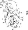
- the pump 22 has a gerotor drive, wherein an inner rotor 50, shown in FIG. 6 (illustrated with the pump cover plate 23 removed for illustrative and descriptive purposes), is rotatable driven by the drive shaft 32 to in turn rotatable drive an outer rotor 52.
- the inner rotor 50 is fixedly secured to the shaft 32 for rotation about axis A with the drive shaft 32.
- a pump end 32A of the shaft 32 is positioned adjacent or next to the pump cover plate 23, as shown in FIG. 4 , and freely rotates.
- a motor end 32B of the shaft is secured by an end bracket 72.
- the outer rotor 52 is rotatably received in the pump parts housing 21, and particularly the pump chamber 51 thereof.
- the pump chamber 51 and the outer surface of the outer rotor 52 are cylindrical, and the pump chamber 51 is radially isolated from the part of the housing 21 defined the passageway 33.
- rotation of the inner rotor 50 also rotates the outer rotor 52 via their intermeshed teeth to pressurize the input fluid received in areas between the complimentary parts for output from the pump 22, and thus such details are not described here.
- Other types of pump parts for pressurizing input fluid may also be used in pump 22 in accordance with other embodiments, including gear pumps, and thus pump 22 should not be limited to gerotor-type pumps.
- the passageway 33 is and forms part of the outlet passage 27 for directing pressurized fluid from the pump 22.
- the passageway 33 may be curved or crescent shaped.
- the shape of the passageway 33 is not meant to be limiting.
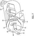
- FIG. 7 shows additional details of the port plate 40 of the pump 22, with the parts housing 21 and rotor 50, 52 of the pump 22 removed therefrom for illustrative and descriptive purposes.
- the port plate 40 has an opening 35 for receipt of the drive shaft 32 therethrough.
- Transfer outlet opening 42 aligns with the passageway 33 of the parts housing 21.
- the transfer outlet opening 42 may be curved or crescent shaped; however, such a shape is not intended to be limiting.
- the shape of the port 31, passageway 33, and transfer outlet opening 42 substantially corresponds or are substantially similar; in another embodiment, the port and passages are shaped or formed such that at least a portion of each is aligned with adjacent part(s) so as to form the outlet passage 27 therethrough.
- a controller-side or transfer outlet port 44 or opening for directing pressurized output fluid from the pump 22 is also provided in the port plate 40 and illustrated in FIG. 4.
- This port 44 may also be curved or crescent shaped, in accordance with an embodiment, but again is not limited in its shape.
- the controller-side outlet port 44 may be positioned radially inward relative to the transfer outlet opening 42, e.g., closer to the opening 35 for the drive shaft 32.
- the port plate 40 of the pump 22 is provided adjacent to and against a cover plate 46 which is connected to the motor casing 30, either as a separate part or formed integrally therewith.
- the pump housing 24 has connectors 19 (see FIG. 2 ) whose openings are aligned with openings of connectors 45 (e.g., see FIG. 7 and 8 ) on the cover plate 46. Fasteners and/or bolts (not shown) may be inserted through the aligned openings to connect and secure the pump housing 24 and connected pipes 14, 18 to the cover plate 46, and thus to the motor casing 30.
- the pump assembly 10 can be mounted within a vehicle by inserting fasteners and/or mounting bolts through holes in mounting portions 20 provided on the pump housing 24 (e.g., near assembly outlet 16) and motor casing 30, and securing the fasteners/bolts to the vehicle.
- the cover plate 46 may be formed from any number of heat conductive materials, such as aluminum or other metals.
- the cover plate 46 has a first axial side 47 and a second axial side 49 (see also, e.g., FIGS. 11 and 12 ).
- the first axial side 47 of the cover plate 46 is shown in FIG. 8 (wherein the pump 22 and port plate 40 are removed for illustrative and descriptive purposes).
- the first axial side 47 (also referred to as the pump-facing side) of the cover plate 46 faces the pump 22 and is in contact with a bottom or back axial side of the port plate 40.
- the second axial side 49 also referred to as the controller-facing side) of the cover plate 46, shown in FIG. 11 , for example, faces the controller 56 and its associated parts.
- the second axial side 49 includes a bushing 60, that extends from its motor-facing surface, for receiving the drive shaft 32.
- the bushing 60 receives the drive shaft 32 through its longitudinal opening (see FIG. 4 ), for example.
- the drive shaft 32 rotates about axis A relative to the bushing 60.
- the bushing 60 may include an indentation 64 (see FIG. 12 ) in its outer surface for receipt of an O-ring 63 (see FIG. 9 ) therein, for example.
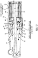
- a small flow portion of pressurized fluid may be directed from the pump 22 between an inner surface of the bushing 60 and an outer surface of the drive shaft 32 and towards the motor 28 (see arrows in FIG. 17 and FIG. 18 ). This fluid flow may assist in removing heat from the motor 28.
- the fluid may be directed through the bushing(s) of the motor 28 and between the rotor 34 and stator 36 to lubricate and cool the magnets and windings 74, as shown in FIG. 18 .
- the fluid can be output or exhausted from the motor casing 30 at its end near the end bracket 72, for example.
- the motor casing 30 includes a compartment 76 (see FIG. 18 ) formed between an end of the motor 28 and an end bracket 78 of the motor casing 30 for containing fluid therein before it is exhausted or expelled from the motor casing 30.
- the pump assembly 10 may include a port or outlet 80 for outputting the small flow portion at the motor side, such as back to a lubricant source / sump or tank, such that it may be further cooled (e.g., cooled from approximately 170 degrees Centigrade (as a result of convection from the motor to the fluid), to approximately 125-130 degrees Centigrade within the sump or tank).
- a lubricant source / sump or tank such that it may be further cooled (e.g., cooled from approximately 170 degrees Centigrade (as a result of convection from the motor to the fluid), to approximately 125-130 degrees Centigrade within the sump or tank).
- the first axial side 47 of the cover plate 46 has a transfer recess 48 formed therein for directing output fluid from the pump (i.e., from the controller-side or transfer outlet port 44) in a radial direction across a surface on the first axial side 47 of the cover plate 46 and circumferentially around the drive shaft 32.
- the transfer recess 48 directs pressurized fluid towards the outlet passage 27 of the pump 22.
- the transfer recess 48 comprises an indentation that extends an axial depth D from the surface and into the first axial side 47 of the plate 46 (see also FIG. 4 ).
- a channel is formed in-between the back side of the port plate 40 and the recess 48 (i.e., due to the depth D of the recess extending into the cover plate 46 (that is, in towards the motor side).
- cover plate 46 acts as a heat conductive plate between the pump and the controller to conduct heat from the controller of the pump assembly 10.
- a radial width (i.e., a distance from a point near the driving shaft 32 to a point (edge of the recess 48) that is positioned radially outward towards an outer edge of the cover plate 46) of the transfer recess 48 around or relative to the drive shaft 32 can vary in dimension and shape.
- the recess 48 has a generally circular shape 48A as well as a peninsula-shaped portion 48B connected to the circular shape, as illustrated in FIG. 8 , for example.
- the generally circular shape 48A may correspond to an internal receiving space of the pump parts housing 21 that contains the rotors 50, 52 therein, and the peninsula-shaped portion 48B may correspond to the shape to the outlet passage 27, including passageway 33, and transfer outlet opening 42.
- the shape of the transfer recess 48 in the cover plate 46 is not intended to be limiting.
- the indentation or depth D of the transfer recess 48 covers at least 50% of the surface area of the cover plate 46 to increase the amount of heat transfer to the fluid / lubricant and overall heat removed as the fluid flows therefrom.
- both of the port plate 40 and cover plate 46 may include a recess or indentation therein, each recess or indentation having an axial depth, that, when the plates 40, 46 are positioned against each other and assembled, their respective recesses / indentations are aligned to form the channel or a slot, i.e., a transfer recess 48, therebetween.
- the depth of the recesses in both of the plates 40, 46 may be different or substantially equal.
- the controller 26 is configured to operate or drive the electric motor 28 (e.g., control a magnetic field of the stator 36 of the motor 28), to thus control the pump 22.
- the controller 26 and its components may be contained within the motor casing 30 by securing the cover plate 46 thereto.
- the cover plate 46 may include a flange portion 65 (see also FIGS. 11 and 12 ) that is aligned against an edge 57 of the motor casing 30.
- a neck portion 67 extends from the second axial side 49 of the cover plate 46 and is press-fit into the motor casing 30 to sealingly secure and contain components of the controller 26 from the fluid of the pump 22.
- One or more O-rings or seals may also be used.
- Other methods or devices for securing the cover plate 46 to the motor casing 30, however, may also be used.
- the controller 26 includes an electronic control unit, or ECU, 54 that has multiple capacitors 56 associated therewith ( FIG. 9 is illustrated with the cover plate 46 removed for illustrative and descriptive purposes).
- the capacitors 56 are arranged in a spaced configuration on an upper side or pump-facing side 68 of the ECU 54 such that they are positioned around the drive shaft 32 in a circumferentially spaced relationship.
- FIG. 11 shows the second (i.e., controller-facing) axial side 49 of the cover plate 46 wherein the neck portion 67 includes circumferentially spaced indentations 58 to accommodate and receive each of the capacitors 56.
- thermal paste is provided between ECU 54 and the cover plate 49 to increase conduction.
- thermal paste may be provided within each of the indentations 58 between the capacitors 56 and an inside thereof.
- the ECU 54 includes a central hole therein (see FIGS. 9 and 15 ) to allow the drive shaft 32 to extend through.
- capacitors 56 Although four capacitors 56 are illustrated in FIG. 9 and FIG. 10 , for example, the number of capacitors is not intended to be limited. Any number of capacitors 56 may be associated with the controller or its circuit board(s). In addition, although not discussed in detail herein, it should be understood that any number of other electrical and electronic parts, sensors, chips, etc. may be used and/or provided as part of the ECU 54 and/or mounted on the board.
- FIG. 10 and FIGS. 14-15 show additional parts of the controller 26 that include a BUS board 66 (MOSFET/ printed circuit board (PCB) with integrated LIN inductors and position sensors (generally represented as components, labeled 70) mounted thereon.
- the BUS board 66 is positioned adjacent to the motor 28 and is used to connecting stator windings of the stator 36 together.
- the BUS board 66 also includes a central hole to allow the drive shaft 32 to extend through, as shown in FIG. 14 .
- the BUS board 66 and ECU 54 are stacked around the drive shaft 32 and electrically connected together, as shown in FIG. 15 .
- the controller 26 may be electrically coupled to a power source (e.g., battery) via a local interconnect network (LIN) bus interface, as graphically represented in FIG. 16 .
- a power source e.g., battery
- LIN local interconnect network
- positive and negative connectors of the LIN interface may be overmolded onto an inner surface of the motor casing 30 that is positioned adjacent to the controller 26. The positioning of the connectors on the motor casing 30 reduces damage and/or failure.
- conventionally, positive and negative power connectors are also overmolded into the controller cover.
- the LIN interface and battery may be electrically connected to the BUS board 66 at points shown in FIG. 15 , for example.
- the connections may be provided on a flange portion of the BUS board 66 that extends radially outward from the board and/or ECU 54, so that they extend towards the overmolded interface and parts within the motor casing 30.
- flowing the output fluid along the cover plate 46 maintains the temperature of the controller 26 below a predetermined temperature to thus avoid failure of the electronic components of the controller 26.
- the controller components radiate and/or conduct heat towards the surrounding housing parts.
- the assembly of the capacitors 56 within the indentations 58 of the cover plate 46 may aid in maximizing heat transfer from the capacitors 56 to the cover plate 46.
- the flowing output fluid conductively absorbs any heat from the cover plate 46.
- fluid is input via inlet pipe 14 to the pump parts and pressurized.
- Pressurized fluid is directed from the transfer outlet port 44 and in the transfer recess 48 of the cover plate 46. It is then directed through and around the formed channel / transfer passage and against the surface of the cover plate 46 (e.g., around the generally circular shape of the recess 48 which extends in a radial direction) and/or port plate 40, as represented by the arrows in FIG. 8 (see also FIG. 17 ).
- the formed channel of the transfer recess 48 is further in fluid communication with the outlet passage 27 of the pump 22 (e.g., via the peninsula-shaped portion).
- the recess 48 further directs the pressurized fluid from the formed channel / transfer passage towards the transfer outlet opening 42 of the port plate 40 for output through the outlet passage 27 and pump outlet port 31.
- the outlet passage thus fluidly communicates the transfer path formed between the pump 22 and cover plate 46 with the assembly outlet 16 to discharge the pressurized fluid.
- a portion of pressurized fluid may be directed through and beyond the bushing 60 and towards the motor 28 to lubricate and cool the magnets and windings 74, as shown in FIG. 18 .
- the fluid can be output or exhausted from the motor casing 30 via the port or outlet 80 to a lubricant source / sump or tank.
- the sandwiching of the components of the controller 26 between the pump 22 and the motor 28 as described herein produces a design layout with greater performance and integration of the controller and motor within a sealed and integrated assembly.
- the disclosed design includes active, internal cooling of both the controller and the motor / bushing - both on the pump side (via heat transfer from the MOSFET/PCB/BUS board 66 and ECU 54 of the controller 56 to the fluid) and on the motor side (by pushing pressurized fluid through the bushing 60 for heat transfer from parts of the motor 28) - while still providing a substantially full output flow of the pump.
Description
- The present disclosure is generally related to a pump for providing pressurized fluid to a system. More specifically, the pump is associated with an engine and has an integrated controller.
- It is known, in some cases, to provide a dedicated electrical motor and a controller (with a circuit board and other electrical components) for operation of lubricant pump. The controller requires a large surface area and cooling interface to remove heat generated by efficiency losses. This results in limited space for the pump, particularly because the space to accommodate installation of the pump, motor, and controller is typically predefined and already limited. With limited space for the pump, optimization of pump performance can be an issue.
- Some designs, such as shown in
FIG. 1 , provide the controller at a back or end of the motor, with the pump on the opposite end of the motor. Other known designs include the pump flanked at its ends by the controller and the motor. During operation of the pump and engine, the temperature rises within the housings. High temperatures may cause problems in the pump parts and controller, and may even lead to failure. In the above-mentioned types of configurations, the controller is typically cooled only by the atmospheric air flow. - In addition, conventionally, positive and negative power connectors are also overmolded into the controller cover. The positioning of the connectors on the controller cover or housing also subjects them to damage and/or failure.
- Also, in traditional designs, in order to produce the desired displacement from the pump, the diameter of the pumping elements tends to be larger in diameter and length than what is optimal. This results in a need for a higher torque to drive the pump, which is undesirable.
-
DE 10 2007 036239A1 describes a method for removing heat from components of a liquid pump; a device for carrying out the method; and a use of the device.US 2016/061221A1 describes an electric water pump with coolant passage.DE 10 2007 036240A1 describes a liquid pump and use of the liquid pump.WO 2012/024778A1 describes an electric water pump with stator cooling.EP 2 199 617 A2 describes a centrifugal pump which can be operated by an electronically commutated direct current motor with an axial gap, with a drying chamber in which a wound stator is accommodated and a fluid-fillable pump chamber in which permanent magnetic pump impeller is rotatably accommodated, the pump impeller being separated from the stator by a gap plate, which is equipped with a return ring, to which several poles connect, and a circuit board is connected and in thermally conductive contact and comprises a heat conducting body made of a light metal with good heat conductivity. - A pump assembly according to claim 1 is disclosed.
- Further, a method for cooling a pump assembly according to claim 15 is disclosed.
- Other aspects, features, and advantages of the present disclosure will become apparent from the following detailed description, the accompanying drawings, and the appended claims.
-
-
FIG. 1 shows an example of a pump according to the prior art. -
FIG. 2 is an isometric view of a pump assembly in accordance with an embodiment of this disclosure. -
FIG. 3 is a side view of the pump assembly ofFIG. 2 . -
FIG. 4 is a cross-sectional view of the pump assembly as taken along line 4-4 inFIG. 2 , showing components in their housings. -
FIG. 5 is an isometric view of parts of the pump assembly ofFIG. 2 , with the pump hydraulic housing removed and showing parts of the pump. -
FIG. 6 is an isometric view of parts of the pump assembly ofFIG. 2 , with the pump cover plate removed and showing internal parts of the pump. -
FIG. 7 is an isometric view of parts of the pump assembly ofFIG. 2 , with portions of the pump removed and showing a port plate of the pump. InFIG. 7 , the pump housing and parts are removed. -
FIG. 8 is an isometric view of parts of the pump assembly ofFIG. 2 , with the pump and port plate removed, showing a first axial side of a cover plate. -
FIG. 9 is an isometric view of parts of the pump assembly ofFIG. 2 , with the cover plate removed and showing parts of the controller within the pump assembly and a shaft, in accordance with an embodiment. InFIG. 9 , the shaft housing is removed. -
FIG. 10 illustrates parts of the controller provided within the pump assembly, in accordance with an embodiment. -
FIG. 11 illustrates a second axial side of the cover plate shown inFIG. 8 . -
FIG. 12 is an alternate view of the cover plate ofFIG. 11 . -
FIG. 13 is an isometric view of parts of a motor provided in a motor housing of the pump assembly ofFIG. 2 , in accordance with an embodiment. -
FIGS. 14 and 15 are isometric views of a circuit board and capacitors of the controller connected to the shaft and the motor ofFIG. 13 , in accordance with an embodiment. -
FIG. 16 is a graphical representation of electrical connections and interface of the pump assembly, in accordance with an embodiment. -
FIG. 17 is a graphical representation of the fluid flow within the pump assembly ofFIG. 2 . -
FIG. 18 illustrates part of the cross section of the pump assembly including a path for a flow of fluid for cooling parts of the motor. - The location, direction, and use of the term "side" herein and throughout this disclosure with reference to the
controller 26 and any of the components of thepump assembly 10 are not intended to be limiting, and it should be understood that such features could also be referred to as a top, bottom, upper, lower, first, second, etc. in this disclosure. The location, direction, and corresponding terms are simply for explanatory purposes with reference to the Figures of the illustrated embodiment. In addition, examples and terms described with regards to direction are for explanatory purposes only; it should be understood that, in some cases, the description of direction and/or side may be altered based on a positioning or mounting of the disclosed pump assembly within a vehicle. Accordingly, such terms should be understood to refer to the illustrated exemplary embodiments and not be construed as being intended to limit the assembly when mounted or configured for use within a vehicle or other machine. -
FIGS. 2 and3 illustrate apump assembly 10, in accordance with an embodiment herein, with its housing and components positioned longitudinally along an axis A. Thepump assembly 10 includes anassembly inlet 12 for inputting fluid, such as a lubricant (e.g., oil or transmission fluid), and anassembly outlet 16 for outputting fluid, i.e., fluid that is pressurized by apump 22 contained therein. Thepump assembly 10 may supply pressurized fluid to a transmission or an engine of an automotive vehicle, for example. In an embodiment, the direction of flow into theassembly inlet 12 and/or from theassembly outlet 16 may be perpendicular to an overall axial length of thepump assembly 10. In another embodiment, at least one of theinlet 12 and/oroutlet 16 direct flow into the pump in a perpendicular or angled direction relative to the longitude or axial length of thepump assembly 10. In the illustrated embodiment, the fluid enters thepump assembly 10 through the assembly inlet 12 (e.g., vertically or horizontally) and is guided through an inlet passage defined by aninlet pipe 14 to the pump 22 (e.g., in a longitudinal or axial direction). Theinlet pipe 14 has an axial length and is fluidly connected to thepump 22 via aninlet 25 thereof (e.g., seeFIG. 5 ), which is further described later. Pressurized fluid from thepump 22 is output via an output passage defined by an outlet pipe 18 (e.g., in a longitudinal or axial direction) and through the assembly outlet 16 (e.g., vertically or horizontally). Theoutlet pipe 18 has an axial length and is parallel to theinlet pipe 14. The input flow of fluid throughpipe 14 and the output flow of fluid throughpipe 18 are in generally parallel but have opposite directions (as compared to one another). Each of thepipes 14 and/or 18 may have generally laminar flow of fluid therethrough. -
Pipes inlet pipe 14 and/oroutlet pipe 18 as shown in the Figures is not intended to be limiting.Pipes pipe 14 and/or 18. Moreover, the length(s) of the pipe(s) 14, 18 may be adjusted to accommodate other parts associated with the pump, e.g., such as a pressure relief valve, which are not specifically illustrated here. In accordance with an embodiment, the axial length of thepipes pump assembly 10 is minimized thereby providing a more compact package for installation. This in turn allows for more options to minimize leakage at higher temperatures and to reduce the diameter of the pumping elements. - In the
pump assembly 10, acontroller 26 is housed therein and thepump 22 and anelectric motor 28 are on opposing axial sides of thecontroller 26. That is, thecontroller 26 is axially flanked by thepump 22 and themotor 28. As seen in the cross-sectional view ofFIG. 4 , for example, thepump 22 and itshousing 24 are provided on one side (a "pump side") (e.g., a left side as shown inFIG. 4 ) of thecontroller 26 and themotor 28 and itscasing 30 are provided on an opposite axial side (a "motor side") (e.g., a right side as shown inFIG. 4 ) of thecontroller 26. In an embodiment, thepump housing 22 and themotor casing 30 are connected together to contain and house thecontroller 26 within thepump assembly 10. Inside thepump assembly 10, adrive shaft 32 connects theelectric motor 28 to thepump 22. Thedrive shaft 32 is driven about axis A by theelectric motor 28 to drive the components of thepump 22. Thecontroller 26 controls and thus drives theelectric motor 28 to drive theshaft 32. - The
electric motor 28 includes arotor 34 and astator 36, which are shown inFIG. 13 . Therotor 34 is connected to theshaft 32 is contained within thecasing 30 along with thestator 36. Themotor casing 30 is generally cylindrical and thestator 36 may be fixed thereto. - Referring back to
FIGS. 2 and3 , in thepump assembly 10, theinlet pipe 14 andoutlet pipe 18 are fluidly connected to thepump 22. Thepump 22 is encased by a pumphydraulic housing 24, also referred to herein as apump casing 24. In accordance with an embodiment, thepump casing 24 may be integrally formed with theinlet pipe 14 andoutlet pipe 18. Thepump casing 24 encloses the functional pump parts therein and may be shaped to accommodate its pumping parts as well as anoutlet passage 27 for directing output flow towards the outlet passage defined in theoutlet pipe 18. As shown inFIG. 5 , for example, thepump 22 includespump cover plate 23, aparts housing 21 and aport plate 40. Thecover plate 23 andport plate 40 are provided at opposite ends of theparts housing 21. When assembled, in accordance with one embodiment, the pump casing or pumphydraulic housing 24 surrounds the parts housing 21 to contain the pump components, as shown inFIG. 4 . Alternatively, in another embodiment, the pump part may be configured for containment within the pumphydraulic housing 24 and a distinct parts housing 21 need not be provided. -
FIG. 5 , illustrated here with the pumphydraulic housing 24 removed for illustrative and descriptive purposes, shows that thepump cover plate 23 includes theinlet port 25 or opening for receiving input fluid from theinlet pipe 14. Thepump cover plate 23 also has anoutlet port 31 for thepump 22 that aligns with a passageway 33 (seeFIG. 6 ) of the parts housing 21 to form theoutlet passage 27, which may be aligned with the suction side of thepump 22. Theoutlet passage 27 of thepump 22 directs any output pressurized fluid from thepump 22 to (and through) theoutlet pipe 18. Theoutlet passage 27 is radially adjacent to and isolated from a pump chamber 51 (shown inFIG. 6 ). In the exemplary illustrated embodiment, theoutlet passage 27 andport 31 are curved or crescent shaped. Theinlet port 25 may also be curved or crescent shaped. The illustrated and described shape of theport 25 and/oroutlet passage 27 andport 31, however, is not meant to be limiting. - As described in greater detail below, the output pressurized fluid from the
pump 22 is also used for internal thermal management of thepump assembly 10. In particular, because thecontroller 26 is temperature sensitive, the pressurized output flow is directed such that it is circulated near thecontroller 26 in order to receive and remove heat radiated or conducted from electronic components of thecontroller 26. Accordingly, the herein disclosed design preferably maintains the temperature of thecontroller 26 below a predetermined temperature to avoid failure of the electronic components of thecontroller 26, and thus, thepump assembly 10. - The type of
pump 22 and its parts provided in thepump assembly 10 is not limited. In accordance with an embodiment, thepump 22 has a gerotor drive, wherein aninner rotor 50, shown inFIG. 6 (illustrated with thepump cover plate 23 removed for illustrative and descriptive purposes), is rotatable driven by thedrive shaft 32 to in turn rotatable drive anouter rotor 52. Theinner rotor 50 is fixedly secured to theshaft 32 for rotation about axis A with thedrive shaft 32. Apump end 32A of theshaft 32 is positioned adjacent or next to thepump cover plate 23, as shown inFIG. 4 , and freely rotates. As shown inFIG. 4 , amotor end 32B of the shaft is secured by anend bracket 72. Referring back toFIG. 6 , theouter rotor 52 is rotatably received in the pump parts housing 21, and particularly thepump chamber 51 thereof. Thepump chamber 51 and the outer surface of theouter rotor 52 are cylindrical, and thepump chamber 51 is radially isolated from the part of thehousing 21 defined thepassageway 33. As is understood by one of ordinary skill in the art, rotation of theinner rotor 50 also rotates theouter rotor 52 via their intermeshed teeth to pressurize the input fluid received in areas between the complimentary parts for output from thepump 22, and thus such details are not described here. Other types of pump parts for pressurizing input fluid may also be used inpump 22 in accordance with other embodiments, including gear pumps, and thus pump 22 should not be limited to gerotor-type pumps. As noted previously, thepassageway 33 is and forms part of theoutlet passage 27 for directing pressurized fluid from thepump 22. In accordance with an embodiment, thepassageway 33 may be curved or crescent shaped. The shape of thepassageway 33, however, is not meant to be limiting. -
FIG. 7 shows additional details of theport plate 40 of thepump 22, with the parts housing 21 androtor pump 22 removed therefrom for illustrative and descriptive purposes. Theport plate 40 has anopening 35 for receipt of thedrive shaft 32 therethrough. Transfer outlet opening 42 aligns with thepassageway 33 of theparts housing 21. In an embodiment, thetransfer outlet opening 42 may be curved or crescent shaped; however, such a shape is not intended to be limiting. In one embodiment, the shape of theport 31,passageway 33, and transfer outlet opening 42 substantially corresponds or are substantially similar; in another embodiment, the port and passages are shaped or formed such that at least a portion of each is aligned with adjacent part(s) so as to form theoutlet passage 27 therethrough. Also provided in theport plate 40 and illustrated inFIG. 4 is a controller-side ortransfer outlet port 44 or opening for directing pressurized output fluid from thepump 22. Thisport 44 may also be curved or crescent shaped, in accordance with an embodiment, but again is not limited in its shape. The controller-side outlet port 44 may be positioned radially inward relative to thetransfer outlet opening 42, e.g., closer to theopening 35 for thedrive shaft 32. - The
port plate 40 of thepump 22 is provided adjacent to and against acover plate 46 which is connected to themotor casing 30, either as a separate part or formed integrally therewith. To secure thepump 22 in thepump assembly 10, thepump housing 24 has connectors 19 (seeFIG. 2 ) whose openings are aligned with openings of connectors 45 (e.g., seeFIG. 7 and8 ) on thecover plate 46. Fasteners and/or bolts (not shown) may be inserted through the aligned openings to connect and secure thepump housing 24 andconnected pipes cover plate 46, and thus to themotor casing 30. Once assembled, as shown inFIG. 2 , for example, thepump assembly 10 can be mounted within a vehicle by inserting fasteners and/or mounting bolts through holes in mountingportions 20 provided on the pump housing 24 (e.g., near assembly outlet 16) andmotor casing 30, and securing the fasteners/bolts to the vehicle. - The
cover plate 46 may be formed from any number of heat conductive materials, such as aluminum or other metals. - The
cover plate 46 has a firstaxial side 47 and a second axial side 49 (see also, e.g.,FIGS. 11 and 12 ). The firstaxial side 47 of thecover plate 46 is shown inFIG. 8 (wherein thepump 22 andport plate 40 are removed for illustrative and descriptive purposes). The first axial side 47 (also referred to as the pump-facing side) of thecover plate 46 faces thepump 22 and is in contact with a bottom or back axial side of theport plate 40. The second axial side 49 (also referred to as the controller-facing side) of thecover plate 46, shown inFIG. 11 , for example, faces thecontroller 56 and its associated parts. The secondaxial side 49 includes abushing 60, that extends from its motor-facing surface, for receiving thedrive shaft 32. Thebushing 60 receives thedrive shaft 32 through its longitudinal opening (seeFIG. 4 ), for example. Thedrive shaft 32 rotates about axis A relative to thebushing 60. Thebushing 60 may include an indentation 64 (seeFIG. 12 ) in its outer surface for receipt of an O-ring 63 (seeFIG. 9 ) therein, for example. In operation, a small flow portion of pressurized fluid may be directed from thepump 22 between an inner surface of thebushing 60 and an outer surface of thedrive shaft 32 and towards the motor 28 (see arrows inFIG. 17 andFIG. 18 ). This fluid flow may assist in removing heat from themotor 28. The fluid may be directed through the bushing(s) of themotor 28 and between therotor 34 andstator 36 to lubricate and cool the magnets andwindings 74, as shown inFIG. 18 . The fluid can be output or exhausted from themotor casing 30 at its end near theend bracket 72, for example. In an embodiment, themotor casing 30 includes a compartment 76 (seeFIG. 18 ) formed between an end of themotor 28 and anend bracket 78 of themotor casing 30 for containing fluid therein before it is exhausted or expelled from themotor casing 30. Thepump assembly 10 may include a port oroutlet 80 for outputting the small flow portion at the motor side, such as back to a lubricant source / sump or tank, such that it may be further cooled (e.g., cooled from approximately 170 degrees Centigrade (as a result of convection from the motor to the fluid), to approximately 125-130 degrees Centigrade within the sump or tank). - Referring back to
FIG. 8 , the firstaxial side 47 of thecover plate 46 has atransfer recess 48 formed therein for directing output fluid from the pump (i.e., from the controller-side or transfer outlet port 44) in a radial direction across a surface on the firstaxial side 47 of thecover plate 46 and circumferentially around thedrive shaft 32. Along with other parts (e.g., opening 42,passageway 33, etc.) previously described, thetransfer recess 48 directs pressurized fluid towards theoutlet passage 27 of thepump 22. Thetransfer recess 48 comprises an indentation that extends an axial depth D from the surface and into the firstaxial side 47 of the plate 46 (see alsoFIG. 4 ). When theport plate 40 is secured against thecover plate 46, a channel is formed in-between the back side of theport plate 40 and the recess 48 (i.e., due to the depth D of the recess extending into the cover plate 46 (that is, in towards the motor side). As described later, when output fluid flows through this formed channel and into recess 48 (also referred to as a transfer passage), heat is conducted from thecover plate 46 into the fluid or lubricant, which is continuously being removed as output or discharge flow. Accordingly,cover plate 46 acts as a heat conductive plate between the pump and the controller to conduct heat from the controller of thepump assembly 10. - A radial width (i.e., a distance from a point near the driving
shaft 32 to a point (edge of the recess 48) that is positioned radially outward towards an outer edge of the cover plate 46) of thetransfer recess 48 around or relative to thedrive shaft 32 can vary in dimension and shape. In one embodiment, therecess 48 has a generallycircular shape 48A as well as a peninsula-shapedportion 48B connected to the circular shape, as illustrated inFIG. 8 , for example. The generallycircular shape 48A may correspond to an internal receiving space of the pump parts housing 21 that contains therotors portion 48B may correspond to the shape to theoutlet passage 27, includingpassageway 33, andtransfer outlet opening 42. The shape of thetransfer recess 48 in thecover plate 46, however, is not intended to be limiting. In an embodiment, the indentation or depth D of thetransfer recess 48 covers at least 50% of the surface area of thecover plate 46 to increase the amount of heat transfer to the fluid / lubricant and overall heat removed as the fluid flows therefrom. - In another embodiment, both of the
port plate 40 andcover plate 46 may include a recess or indentation therein, each recess or indentation having an axial depth, that, when theplates transfer recess 48, therebetween. The depth of the recesses in both of theplates - The
controller 26 is configured to operate or drive the electric motor 28 (e.g., control a magnetic field of thestator 36 of the motor 28), to thus control thepump 22. Thecontroller 26 and its components may be contained within themotor casing 30 by securing thecover plate 46 thereto. For example, as seen inFIG. 4 , thecover plate 46 may include a flange portion 65 (see alsoFIGS. 11 and 12 ) that is aligned against anedge 57 of themotor casing 30. Aneck portion 67 extends from the secondaxial side 49 of thecover plate 46 and is press-fit into themotor casing 30 to sealingly secure and contain components of thecontroller 26 from the fluid of thepump 22. One or more O-rings or seals may also be used. Other methods or devices for securing thecover plate 46 to themotor casing 30, however, may also be used. - As shown in
FIGS. 9 and10 , thecontroller 26 includes an electronic control unit, or ECU, 54 that hasmultiple capacitors 56 associated therewith (FIG. 9 is illustrated with thecover plate 46 removed for illustrative and descriptive purposes). In an embodiment, for example, thecapacitors 56 are arranged in a spaced configuration on an upper side or pump-facingside 68 of theECU 54 such that they are positioned around thedrive shaft 32 in a circumferentially spaced relationship.FIG. 11 shows the second (i.e., controller-facing)axial side 49 of thecover plate 46 wherein theneck portion 67 includes circumferentially spacedindentations 58 to accommodate and receive each of thecapacitors 56. In an embodiment, thermal paste is provided betweenECU 54 and thecover plate 49 to increase conduction. For example, thermal paste may be provided within each of theindentations 58 between thecapacitors 56 and an inside thereof. TheECU 54 includes a central hole therein (seeFIGS. 9 and15 ) to allow thedrive shaft 32 to extend through. - Although four
capacitors 56 are illustrated inFIG. 9 andFIG. 10 , for example, the number of capacitors is not intended to be limited. Any number ofcapacitors 56 may be associated with the controller or its circuit board(s). In addition, although not discussed in detail herein, it should be understood that any number of other electrical and electronic parts, sensors, chips, etc. may be used and/or provided as part of theECU 54 and/or mounted on the board. -
FIG. 10 andFIGS. 14-15 show additional parts of thecontroller 26 that include a BUS board 66 (MOSFET/ printed circuit board (PCB) with integrated LIN inductors and position sensors (generally represented as components, labeled 70) mounted thereon. TheBUS board 66 is positioned adjacent to themotor 28 and is used to connecting stator windings of thestator 36 together. TheBUS board 66 also includes a central hole to allow thedrive shaft 32 to extend through, as shown inFIG. 14 . TheBUS board 66 andECU 54 are stacked around thedrive shaft 32 and electrically connected together, as shown inFIG. 15 . - The
controller 26 may be electrically coupled to a power source (e.g., battery) via a local interconnect network (LIN) bus interface, as graphically represented inFIG. 16 . For example, positive and negative connectors of the LIN interface may be overmolded onto an inner surface of themotor casing 30 that is positioned adjacent to thecontroller 26. The positioning of the connectors on themotor casing 30 reduces damage and/or failure. In addition, conventionally, positive and negative power connectors are also overmolded into the controller cover. The LIN interface and battery may be electrically connected to theBUS board 66 at points shown inFIG. 15 , for example. The connections may be provided on a flange portion of theBUS board 66 that extends radially outward from the board and/orECU 54, so that they extend towards the overmolded interface and parts within themotor casing 30. - As previously mentioned, flowing the output fluid along the
cover plate 46 maintains the temperature of thecontroller 26 below a predetermined temperature to thus avoid failure of the electronic components of thecontroller 26. The controller components radiate and/or conduct heat towards the surrounding housing parts. The assembly of thecapacitors 56 within theindentations 58 of thecover plate 46 may aid in maximizing heat transfer from thecapacitors 56 to thecover plate 46. The flowing output fluid conductively absorbs any heat from thecover plate 46. - In the illustrated embodiment, during operation of the pump, fluid is input via
inlet pipe 14 to the pump parts and pressurized. Pressurized fluid is directed from thetransfer outlet port 44 and in thetransfer recess 48 of thecover plate 46. It is then directed through and around the formed channel / transfer passage and against the surface of the cover plate 46 (e.g., around the generally circular shape of therecess 48 which extends in a radial direction) and/orport plate 40, as represented by the arrows inFIG. 8 (see alsoFIG. 17 ). The formed channel of thetransfer recess 48 is further in fluid communication with theoutlet passage 27 of the pump 22 (e.g., via the peninsula-shaped portion). Therecess 48 further directs the pressurized fluid from the formed channel / transfer passage towards the transfer outlet opening 42 of theport plate 40 for output through theoutlet passage 27 andpump outlet port 31. The outlet passage thus fluidly communicates the transfer path formed between thepump 22 andcover plate 46 with theassembly outlet 16 to discharge the pressurized fluid. Additionally, a portion of pressurized fluid may be directed through and beyond thebushing 60 and towards themotor 28 to lubricate and cool the magnets andwindings 74, as shown inFIG. 18 . The fluid can be output or exhausted from themotor casing 30 via the port oroutlet 80 to a lubricant source / sump or tank. - The sandwiching of the components of the
controller 26 between thepump 22 and themotor 28 as described herein produces a design layout with greater performance and integration of the controller and motor within a sealed and integrated assembly. Further, the disclosed design includes active, internal cooling of both the controller and the motor / bushing - both on the pump side (via heat transfer from the MOSFET/PCB/BUS board 66 andECU 54 of thecontroller 56 to the fluid) and on the motor side (by pushing pressurized fluid through thebushing 60 for heat transfer from parts of the motor 28) - while still providing a substantially full output flow of the pump. - While the principles of the disclosure have been made clear in the illustrative embodiments set forth above, it will be apparent to those skilled in the art that various modifications may be made to the structure, arrangement, proportion, elements, materials, and components used in the practice of the disclosure.
- It will thus be seen that the features of this disclosure have been fully and effectively accomplished. It will be realized, however, that the foregoing preferred specific embodiments have been shown and described for the purpose of illustrating the functional and structural principles of this disclosure and are subject to change without departure from such principles. Therefore, this disclosure includes all modifications encompassed within the scope of the following claims.
Claims (15)
- A pump assembly defining a longitudinal axis (A), the pump assembly comprising:an assembly inlet (12) for inputting fluid;an inlet passage (14);an assembly outlet (16) for outputting fluid;an electric motor (28) contained within a motor casing (30);a pump (22) having a pump housing (21, 24), the inlet passage for communicating the input fluid longitudinally from the assembly inlet to the pump, the pump having an inlet (25) for receiving input fluid from the inlet passage, at least one rotor (50, 52) for pressurizing the received input fluid, and a transfer outlet port (44) for outputting pressurized fluid;a drive shaft (32) connecting the electric motor to the pump, the drive shaft being configured to be driven about the longitudinal axis by the electric motor;a controller (26) provided within the motor casing and configured to drive the electric motor, wherein the pump and the electric motor are on opposing axial sides of the controller;a heat conductive cover plate (46) positioned between the pump and the controller, the heat conductive cover plate conducting heat from the controller and connected to the motor casing for containing the controller therein, the heat conductive cover plate comprising a first axial side (47) and a second axial side (49), the first axial side of the heat conductive cover plate facing the pump housing and the second axial side of the heat conductive cover plate facing the motor casing, wherein the controller is contained by the second axial side of the heat conductive cover plate;a transfer passage (48) provided in the first axial side of the heat conductive cover plate for receiving the pressurized fluid output from the transfer outlet port (44) of the pump and directing the pressurized fluid along and in contact with the heat conductive cover plate to conduct heat therefrom into the pressurized fluid; andan outlet passage (27, 18) communicating the transfer passage with the assembly outlet (16) to discharge the pressurized fluid, the outlet passage for communicating the pressurized fluid from the pump longitudinally to the assembly outlet,wherein the drive shaft (32) extends through the controller (26) and the heat conductive cover plate (46).
- The pump assembly according to claim 1, wherein the transfer passage (48) is provided in the form of a recess in the heat conductive cover plate (46).
- The pump assembly according to claim 1, wherein the controller (26) comprises a circuit board including a plurality of capacitors, and wherein the second axial side (49) of the heat conductive cover plate (46) comprises indentations therein to accommodate the plurality of capacitors therein.
- The pump assembly according to claim 3, wherein thermal paste is provided within each of the indentations between the capacitors and an inside thereof.
- The pump assembly according to claim 3 or claim 4, wherein the drive shaft (32) extends through the circuit board, and wherein the plurality of capacitors are arranged in a spaced configuration around the drive shaft.
- The pump assembly according to any of the preceding claims, wherein the pump housing (21, 24) and the motor casing (30) are connected to contain and house the controller (26).
- The pump assembly according to any of the preceding claims, wherein the heat conductive cover plate (46) is a cover plate connected to the motor casing (30) for containing the controller (26) therein.
- The pump assembly according to claim 7, wherein the first axial side (47) of the heat conductive cover plate (46) comprises a transfer recess therein for defining the transfer passage (48).
- The pump assembly according to any of the preceding claims, wherein the pump housing (21, 24) is connected to the heat conductive cover plate (46).
- The pump assembly according to any of the preceding claims, wherein the pump housing includes a port plate (40) that is positioned against the heat conductive cover plate (46) and the pump housing comprises the outlet passage (27) radially adjacent and isolated from the pump chamber.
- The pump assembly according to claim 5, wherein thermal paste is provided between the controller (26) and the heat conductive cover plate (46).
- The pump assembly according to claim 1, wherein the outlet passage (27, 18) is parallel to the inlet passage (14) and input flow of fluid through the inlet passage (14) and output flow of the pressurized fluid through the outlet passage (27, 18) is generally parallel and in opposite directions.
- The pump assembly according to claim 10, wherein the port plate (40) has an opening (35) for receipt of the drive shaft (32) therethrough.
- The pump assembly according to claim 1, wherein the transfer passage (48) has a depth that covers at least 50% of a surface area of the heat conductive cover plate (46).
- A method for cooling the pump assembly according to claim 1; the method comprising:driving the electric motor (28) using the controller (26);driving the drive shaft (32);inputting fluid through the assembly inlet (12) of the pump assembly and into the inlet (25) of the pump (22);pressurizing input fluid using the pump (22);outputting pressurized fluid via the transfer outlet port (44) into the transfer passage (48);directing the pressurized fluid along and in contact with the heat conductive plate (46); anddischarging the pressurized fluid through the assembly outlet (16).
Applications Claiming Priority (3)
| Application Number | Priority Date | Filing Date | Title |
|---|---|---|---|
| US201662364540P | 2016-07-20 | 2016-07-20 | |
| US201662404975P | 2016-10-06 | 2016-10-06 | |
| PCT/IB2017/054370 WO2018015903A1 (en) | 2016-07-20 | 2017-07-19 | Pump assembly having integrated controller and motor with internal active cooling |
Publications (3)
| Publication Number | Publication Date |
|---|---|
| EP3488672A1 EP3488672A1 (en) | 2019-05-29 |
| EP3488672A4 EP3488672A4 (en) | 2020-05-13 |
| EP3488672B1 true EP3488672B1 (en) | 2021-10-20 |
Family
ID=60987974
Family Applications (1)
| Application Number | Title | Priority Date | Filing Date |
|---|---|---|---|
| EP17830585.0A Active EP3488672B1 (en) | 2016-07-20 | 2017-07-19 | Pump assembly having integrated controller and motor with internal active cooling |
Country Status (8)
| Country | Link |
|---|---|
| US (1) | US10808697B2 (en) |
| EP (1) | EP3488672B1 (en) |
| JP (1) | JP7029437B2 (en) |
| KR (1) | KR102333614B1 (en) |
| CN (1) | CN109479387B (en) |
| CA (1) | CA3031042C (en) |
| MX (1) | MX2019000773A (en) |
| WO (1) | WO2018015903A1 (en) |
Families Citing this family (4)
| Publication number | Priority date | Publication date | Assignee | Title |
|---|---|---|---|---|
| US11078902B2 (en) * | 2017-08-16 | 2021-08-03 | Parker-Hannifin Corporation | Adapter plate with heat exchanger for a pump and motor |
| CN108799082A (en) * | 2018-08-24 | 2018-11-13 | 上海上涵自动化科技有限公司 | A kind of water cooling intelligent water pump control device |
| CN109819637A (en) * | 2019-04-09 | 2019-05-28 | 苏州玲珑汽车科技有限公司 | A kind of automobile controller cooling system |
| US20220320974A1 (en) * | 2021-03-30 | 2022-10-06 | Nidec Tosok Corporation | Electric pump |
Family Cites Families (24)
| Publication number | Priority date | Publication date | Assignee | Title |
|---|---|---|---|---|
| DE4121430C1 (en) | 1991-06-28 | 1992-11-05 | Grundfos International A/S, Bjerringbro, Dk | |
| JP3814331B2 (en) | 1996-03-18 | 2006-08-30 | 株式会社ミツバ | Motor pump |
| JPH11334616A (en) * | 1998-05-21 | 1999-12-07 | Koyo Seiko Co Ltd | Power steering unit |
| JP2000291557A (en) | 1999-04-07 | 2000-10-17 | Sanden Corp | Electric compressor |
| JP3797463B2 (en) * | 1999-07-29 | 2006-07-19 | 日本電産株式会社 | Motor mounted with hydraulic pump, and manifold suitable for the motor |
| DE602004000976T2 (en) * | 2004-03-05 | 2007-05-03 | C.R.F. S.C.P.A. | Motor compressor unit for motor vehicles |
| GB2418073A (en) * | 2004-09-14 | 2006-03-15 | Dana Automotive Ltd | Mounting for cooling of electronic components in motor pump assembly |
| EP1637741A1 (en) * | 2004-09-17 | 2006-03-22 | Pumpenfabrik Ernst Vogel Gesellschaft m.b.H. | Liquid cooled pump and pump controller |
| JP4829024B2 (en) * | 2006-07-25 | 2011-11-30 | アスモ株式会社 | Water pump |
| DE102007036236A1 (en) | 2007-08-02 | 2009-02-05 | Mahle International Gmbh | Built piston |
| DE102007036240A1 (en) * | 2007-08-02 | 2009-02-05 | Continental Automotive Gmbh | liquid pump |
| DE102007036239A1 (en) * | 2007-08-02 | 2009-02-05 | Continental Automotive Gmbh | Process for removing heat from components of a liquid pump |
| DE102008064162B4 (en) | 2008-12-19 | 2013-06-06 | Bühler Motor GmbH | Centrifugal pump with a fixed axis |
| JP2011185190A (en) * | 2010-03-10 | 2011-09-22 | Ebara Corp | Control device integrated type motor pump |
| JP2012026309A (en) * | 2010-07-21 | 2012-02-09 | Jtekt Corp | Electric pump unit |
| WO2012024778A1 (en) * | 2010-08-25 | 2012-03-01 | Magna Powertrain Inc. | Electric water pump with stator cooling |
| MX2014009363A (en) * | 2012-02-27 | 2014-11-21 | Magna Powertrain America Inc | Electric motor -driven pump. |
| US9360015B2 (en) * | 2012-07-16 | 2016-06-07 | Magna Powertrain Of America, Inc. | Submerged rotor electric water pump with structural wetsleeve |
| DE102012222358A1 (en) * | 2012-12-05 | 2014-06-05 | Mahle International Gmbh | Electric fluid pump |
| FR2999864A1 (en) * | 2012-12-19 | 2014-06-20 | Valeo Systemes Thermiques | COOLING DEVICE FOR PRINTED CIRCUIT BOARD |
| WO2014210093A1 (en) * | 2013-06-28 | 2014-12-31 | Borgwarner Inc. | Charging apparatus for a combustion engine |
| KR101601100B1 (en) * | 2014-08-27 | 2016-03-08 | 현대자동차주식회사 | Electric Water Pump with Coolant Passage |
| US10087932B2 (en) | 2014-11-19 | 2018-10-02 | American Axle & Manufacturing, Inc. | G-rotor pump assembly |
| JP6472678B2 (en) | 2015-02-19 | 2019-02-20 | 日立オートモティブシステムズ株式会社 | Electric oil pump |
-
2017
- 2017-07-19 CA CA3031042A patent/CA3031042C/en active Active
- 2017-07-19 WO PCT/IB2017/054370 patent/WO2018015903A1/en unknown
- 2017-07-19 KR KR1020197005115A patent/KR102333614B1/en active IP Right Grant
- 2017-07-19 CN CN201780044570.2A patent/CN109479387B/en active Active
- 2017-07-19 MX MX2019000773A patent/MX2019000773A/en unknown
- 2017-07-19 EP EP17830585.0A patent/EP3488672B1/en active Active
- 2017-07-19 JP JP2019502093A patent/JP7029437B2/en active Active
- 2017-07-19 US US15/653,690 patent/US10808697B2/en active Active
Also Published As
| Publication number | Publication date |
|---|---|
| JP2019527790A (en) | 2019-10-03 |
| JP7029437B2 (en) | 2022-03-03 |
| WO2018015903A1 (en) | 2018-01-25 |
| US20180023565A1 (en) | 2018-01-25 |
| EP3488672A1 (en) | 2019-05-29 |
| CN109479387B (en) | 2021-03-30 |
| KR102333614B1 (en) | 2021-12-01 |
| MX2019000773A (en) | 2019-06-20 |
| CA3031042A1 (en) | 2018-01-25 |
| CA3031042C (en) | 2023-12-19 |
| KR20190027927A (en) | 2019-03-15 |
| US10808697B2 (en) | 2020-10-20 |
| CN109479387A (en) | 2019-03-15 |
| EP3488672A4 (en) | 2020-05-13 |
Similar Documents
| Publication | Publication Date | Title |
|---|---|---|
| EP3488672B1 (en) | Pump assembly having integrated controller and motor with internal active cooling | |
| JP3872104B2 (en) | Rotary pump | |
| US6986648B2 (en) | Electric pump | |
| EP2920423B1 (en) | Automotive electric liquid pump | |
| US6659737B2 (en) | Electronic fluid pump with an encapsulated stator assembly | |
| KR102014785B1 (en) | Electric motor-driven pump | |
| US9197115B2 (en) | Electric machine cooling | |
| US20130043747A1 (en) | Electric Machine Cooling | |
| CN114060315A (en) | Pump assembly with performance enhanced hose connection port | |
| CN219549116U (en) | Electric oil pump device | |
| CN114270043A (en) | Pump and method of operating the same | |
| CN117662459A (en) | Electric oil pump device | |
| EP4030056A1 (en) | A rotary positive displacement pump | |
| CN117791937A (en) | Electric drive system and vehicle | |
| CN115977965A (en) | Multi-pump device | |
| CN114270042A (en) | Pump and method of operating the same | |
| CN115882642A (en) | Combined type heat dissipation motor |
Legal Events
| Date | Code | Title | Description |
|---|---|---|---|
| STAA | Information on the status of an ep patent application or granted ep patent |
Free format text: STATUS: THE INTERNATIONAL PUBLICATION HAS BEEN MADE |
|
| PUAI | Public reference made under article 153(3) epc to a published international application that has entered the european phase |
Free format text: ORIGINAL CODE: 0009012 |
|
| STAA | Information on the status of an ep patent application or granted ep patent |
Free format text: STATUS: REQUEST FOR EXAMINATION WAS MADE |
|
| 17P | Request for examination filed |
Effective date: 20190220 |
|
| AK | Designated contracting states |
Kind code of ref document: A1 Designated state(s): AL AT BE BG CH CY CZ DE DK EE ES FI FR GB GR HR HU IE IS IT LI LT LU LV MC MK MT NL NO PL PT RO RS SE SI SK SM TR |
|
| AX | Request for extension of the european patent |
Extension state: BA ME |
|
| RIN1 | Information on inventor provided before grant (corrected) |
Inventor name: WANG, LIPING Inventor name: MUIZELAAR, RICHARD |
|
| DAV | Request for validation of the european patent (deleted) | ||
| DAX | Request for extension of the european patent (deleted) | ||
| REG | Reference to a national code |
Ref country code: DE Ref legal event code: R079 Ref document number: 602017048016 Country of ref document: DE Free format text: PREVIOUS MAIN CLASS: H05K0007200000 Ipc: F04C0002100000 |
|
| A4 | Supplementary search report drawn up and despatched |
Effective date: 20200417 |
|
| RIC1 | Information provided on ipc code assigned before grant |
Ipc: F04C 2/10 20060101AFI20200408BHEP Ipc: F04C 15/00 20060101ALI20200408BHEP Ipc: F04C 11/00 20060101ALI20200408BHEP Ipc: F04D 13/06 20060101ALI20200408BHEP Ipc: H02K 7/14 20060101ALI20200408BHEP Ipc: F04D 29/58 20060101ALI20200408BHEP Ipc: F04C 15/06 20060101ALI20200408BHEP Ipc: H05K 7/20 20060101ALI20200408BHEP Ipc: F04C 29/04 20060101ALI20200408BHEP |
|
| GRAP | Despatch of communication of intention to grant a patent |
Free format text: ORIGINAL CODE: EPIDOSNIGR1 |
|
| STAA | Information on the status of an ep patent application or granted ep patent |
Free format text: STATUS: GRANT OF PATENT IS INTENDED |
|
| INTG | Intention to grant announced |
Effective date: 20210506 |
|
| RIN1 | Information on inventor provided before grant (corrected) |
Inventor name: MUIZELAAR, RICHARD Inventor name: WANG, LIPING |
|
| GRAS | Grant fee paid |
Free format text: ORIGINAL CODE: EPIDOSNIGR3 |
|
| GRAA | (expected) grant |
Free format text: ORIGINAL CODE: 0009210 |
|
| STAA | Information on the status of an ep patent application or granted ep patent |
Free format text: STATUS: THE PATENT HAS BEEN GRANTED |
|
| AK | Designated contracting states |
Kind code of ref document: B1 Designated state(s): AL AT BE BG CH CY CZ DE DK EE ES FI FR GB GR HR HU IE IS IT LI LT LU LV MC MK MT NL NO PL PT RO RS SE SI SK SM TR |
|
| REG | Reference to a national code |
Ref country code: GB Ref legal event code: FG4D |
|
| REG | Reference to a national code |
Ref country code: CH Ref legal event code: EP |
|
| REG | Reference to a national code |
Ref country code: DE Ref legal event code: R096 Ref document number: 602017048016 Country of ref document: DE |
|
| REG | Reference to a national code |
Ref country code: IE Ref legal event code: FG4D |
|
| REG | Reference to a national code |
Ref country code: AT Ref legal event code: REF Ref document number: 1440166 Country of ref document: AT Kind code of ref document: T Effective date: 20211115 |
|
| REG | Reference to a national code |
Ref country code: LT Ref legal event code: MG9D |
|
| REG | Reference to a national code |
Ref country code: NL Ref legal event code: MP Effective date: 20211020 |
|
| REG | Reference to a national code |
Ref country code: AT Ref legal event code: MK05 Ref document number: 1440166 Country of ref document: AT Kind code of ref document: T Effective date: 20211020 |
|
| PG25 | Lapsed in a contracting state [announced via postgrant information from national office to epo] |
Ref country code: RS Free format text: LAPSE BECAUSE OF FAILURE TO SUBMIT A TRANSLATION OF THE DESCRIPTION OR TO PAY THE FEE WITHIN THE PRESCRIBED TIME-LIMIT Effective date: 20211020 Ref country code: LT Free format text: LAPSE BECAUSE OF FAILURE TO SUBMIT A TRANSLATION OF THE DESCRIPTION OR TO PAY THE FEE WITHIN THE PRESCRIBED TIME-LIMIT Effective date: 20211020 Ref country code: FI Free format text: LAPSE BECAUSE OF FAILURE TO SUBMIT A TRANSLATION OF THE DESCRIPTION OR TO PAY THE FEE WITHIN THE PRESCRIBED TIME-LIMIT Effective date: 20211020 Ref country code: BG Free format text: LAPSE BECAUSE OF FAILURE TO SUBMIT A TRANSLATION OF THE DESCRIPTION OR TO PAY THE FEE WITHIN THE PRESCRIBED TIME-LIMIT Effective date: 20220120 Ref country code: AT Free format text: LAPSE BECAUSE OF FAILURE TO SUBMIT A TRANSLATION OF THE DESCRIPTION OR TO PAY THE FEE WITHIN THE PRESCRIBED TIME-LIMIT Effective date: 20211020 |
|
| PG25 | Lapsed in a contracting state [announced via postgrant information from national office to epo] |
Ref country code: IS Free format text: LAPSE BECAUSE OF FAILURE TO SUBMIT A TRANSLATION OF THE DESCRIPTION OR TO PAY THE FEE WITHIN THE PRESCRIBED TIME-LIMIT Effective date: 20220220 Ref country code: SE Free format text: LAPSE BECAUSE OF FAILURE TO SUBMIT A TRANSLATION OF THE DESCRIPTION OR TO PAY THE FEE WITHIN THE PRESCRIBED TIME-LIMIT Effective date: 20211020 Ref country code: PT Free format text: LAPSE BECAUSE OF FAILURE TO SUBMIT A TRANSLATION OF THE DESCRIPTION OR TO PAY THE FEE WITHIN THE PRESCRIBED TIME-LIMIT Effective date: 20220221 Ref country code: PL Free format text: LAPSE BECAUSE OF FAILURE TO SUBMIT A TRANSLATION OF THE DESCRIPTION OR TO PAY THE FEE WITHIN THE PRESCRIBED TIME-LIMIT Effective date: 20211020 Ref country code: NO Free format text: LAPSE BECAUSE OF FAILURE TO SUBMIT A TRANSLATION OF THE DESCRIPTION OR TO PAY THE FEE WITHIN THE PRESCRIBED TIME-LIMIT Effective date: 20220120 Ref country code: NL Free format text: LAPSE BECAUSE OF FAILURE TO SUBMIT A TRANSLATION OF THE DESCRIPTION OR TO PAY THE FEE WITHIN THE PRESCRIBED TIME-LIMIT Effective date: 20211020 Ref country code: LV Free format text: LAPSE BECAUSE OF FAILURE TO SUBMIT A TRANSLATION OF THE DESCRIPTION OR TO PAY THE FEE WITHIN THE PRESCRIBED TIME-LIMIT Effective date: 20211020 Ref country code: HR Free format text: LAPSE BECAUSE OF FAILURE TO SUBMIT A TRANSLATION OF THE DESCRIPTION OR TO PAY THE FEE WITHIN THE PRESCRIBED TIME-LIMIT Effective date: 20211020 Ref country code: GR Free format text: LAPSE BECAUSE OF FAILURE TO SUBMIT A TRANSLATION OF THE DESCRIPTION OR TO PAY THE FEE WITHIN THE PRESCRIBED TIME-LIMIT Effective date: 20220121 Ref country code: ES Free format text: LAPSE BECAUSE OF FAILURE TO SUBMIT A TRANSLATION OF THE DESCRIPTION OR TO PAY THE FEE WITHIN THE PRESCRIBED TIME-LIMIT Effective date: 20211020 |
|
| REG | Reference to a national code |
Ref country code: DE Ref legal event code: R097 Ref document number: 602017048016 Country of ref document: DE |
|
| PG25 | Lapsed in a contracting state [announced via postgrant information from national office to epo] |
Ref country code: SM Free format text: LAPSE BECAUSE OF FAILURE TO SUBMIT A TRANSLATION OF THE DESCRIPTION OR TO PAY THE FEE WITHIN THE PRESCRIBED TIME-LIMIT Effective date: 20211020 Ref country code: SK Free format text: LAPSE BECAUSE OF FAILURE TO SUBMIT A TRANSLATION OF THE DESCRIPTION OR TO PAY THE FEE WITHIN THE PRESCRIBED TIME-LIMIT Effective date: 20211020 Ref country code: RO Free format text: LAPSE BECAUSE OF FAILURE TO SUBMIT A TRANSLATION OF THE DESCRIPTION OR TO PAY THE FEE WITHIN THE PRESCRIBED TIME-LIMIT Effective date: 20211020 Ref country code: EE Free format text: LAPSE BECAUSE OF FAILURE TO SUBMIT A TRANSLATION OF THE DESCRIPTION OR TO PAY THE FEE WITHIN THE PRESCRIBED TIME-LIMIT Effective date: 20211020 Ref country code: DK Free format text: LAPSE BECAUSE OF FAILURE TO SUBMIT A TRANSLATION OF THE DESCRIPTION OR TO PAY THE FEE WITHIN THE PRESCRIBED TIME-LIMIT Effective date: 20211020 Ref country code: CZ Free format text: LAPSE BECAUSE OF FAILURE TO SUBMIT A TRANSLATION OF THE DESCRIPTION OR TO PAY THE FEE WITHIN THE PRESCRIBED TIME-LIMIT Effective date: 20211020 |
|
| PLBE | No opposition filed within time limit |
Free format text: ORIGINAL CODE: 0009261 |
|
| STAA | Information on the status of an ep patent application or granted ep patent |
Free format text: STATUS: NO OPPOSITION FILED WITHIN TIME LIMIT |
|
| 26N | No opposition filed |
Effective date: 20220721 |
|
| PG25 | Lapsed in a contracting state [announced via postgrant information from national office to epo] |
Ref country code: AL Free format text: LAPSE BECAUSE OF FAILURE TO SUBMIT A TRANSLATION OF THE DESCRIPTION OR TO PAY THE FEE WITHIN THE PRESCRIBED TIME-LIMIT Effective date: 20211020 |
|
| PG25 | Lapsed in a contracting state [announced via postgrant information from national office to epo] |
Ref country code: SI Free format text: LAPSE BECAUSE OF FAILURE TO SUBMIT A TRANSLATION OF THE DESCRIPTION OR TO PAY THE FEE WITHIN THE PRESCRIBED TIME-LIMIT Effective date: 20211020 |
|
| PG25 | Lapsed in a contracting state [announced via postgrant information from national office to epo] |
Ref country code: MC Free format text: LAPSE BECAUSE OF FAILURE TO SUBMIT A TRANSLATION OF THE DESCRIPTION OR TO PAY THE FEE WITHIN THE PRESCRIBED TIME-LIMIT Effective date: 20211020 |
|
| REG | Reference to a national code |
Ref country code: CH Ref legal event code: PL |
|
| REG | Reference to a national code |
Ref country code: BE Ref legal event code: MM Effective date: 20220731 |
|
| PG25 | Lapsed in a contracting state [announced via postgrant information from national office to epo] |
Ref country code: LU Free format text: LAPSE BECAUSE OF NON-PAYMENT OF DUE FEES Effective date: 20220719 Ref country code: LI Free format text: LAPSE BECAUSE OF NON-PAYMENT OF DUE FEES Effective date: 20220731 Ref country code: CH Free format text: LAPSE BECAUSE OF NON-PAYMENT OF DUE FEES Effective date: 20220731 |
|
| PG25 | Lapsed in a contracting state [announced via postgrant information from national office to epo] |
Ref country code: BE Free format text: LAPSE BECAUSE OF NON-PAYMENT OF DUE FEES Effective date: 20220731 |
|
| REG | Reference to a national code |
Ref country code: GB Ref legal event code: 746 Effective date: 20230609 |
|
| REG | Reference to a national code |
Ref country code: DE Ref legal event code: R084 Ref document number: 602017048016 Country of ref document: DE |
|
| PG25 | Lapsed in a contracting state [announced via postgrant information from national office to epo] |
Ref country code: IE Free format text: LAPSE BECAUSE OF NON-PAYMENT OF DUE FEES Effective date: 20220719 |
|
| P01 | Opt-out of the competence of the unified patent court (upc) registered |
Effective date: 20230628 |
|
| PGFP | Annual fee paid to national office [announced via postgrant information from national office to epo] |
Ref country code: IT Payment date: 20230721 Year of fee payment: 7 Ref country code: GB Payment date: 20230725 Year of fee payment: 7 |
|
| PGFP | Annual fee paid to national office [announced via postgrant information from national office to epo] |
Ref country code: FR Payment date: 20230725 Year of fee payment: 7 Ref country code: DE Payment date: 20230726 Year of fee payment: 7 |
|
| PG25 | Lapsed in a contracting state [announced via postgrant information from national office to epo] |
Ref country code: HU Free format text: LAPSE BECAUSE OF FAILURE TO SUBMIT A TRANSLATION OF THE DESCRIPTION OR TO PAY THE FEE WITHIN THE PRESCRIBED TIME-LIMIT; INVALID AB INITIO Effective date: 20170719 |