EP3488628B1 - Procédé et système pour des transmissions multi-protocole orthogonales - Google Patents
Procédé et système pour des transmissions multi-protocole orthogonales Download PDFInfo
- Publication number
- EP3488628B1 EP3488628B1 EP16767021.5A EP16767021A EP3488628B1 EP 3488628 B1 EP3488628 B1 EP 3488628B1 EP 16767021 A EP16767021 A EP 16767021A EP 3488628 B1 EP3488628 B1 EP 3488628B1
- Authority
- EP
- European Patent Office
- Prior art keywords
- lte
- subcarriers
- ofdm
- ofdm1
- signal
- Prior art date
- Legal status (The legal status is an assumption and is not a legal conclusion. Google has not performed a legal analysis and makes no representation as to the accuracy of the status listed.)
- Active
Links
- 230000005540 biological transmission Effects 0.000 title claims description 189
- 238000000034 method Methods 0.000 title claims description 59
- 238000013507 mapping Methods 0.000 claims description 47
- 230000007774 longterm Effects 0.000 claims description 9
- 230000008054 signal transmission Effects 0.000 claims description 9
- 238000012549 training Methods 0.000 claims description 6
- 238000005516 engineering process Methods 0.000 description 46
- 230000015654 memory Effects 0.000 description 29
- 238000004891 communication Methods 0.000 description 25
- 238000001228 spectrum Methods 0.000 description 24
- 238000010586 diagram Methods 0.000 description 20
- 239000000969 carrier Substances 0.000 description 14
- 210000004027 cell Anatomy 0.000 description 12
- 230000006870 function Effects 0.000 description 11
- 238000013459 approach Methods 0.000 description 8
- 238000001514 detection method Methods 0.000 description 8
- 238000007726 management method Methods 0.000 description 7
- 230000003595 spectral effect Effects 0.000 description 7
- 230000009286 beneficial effect Effects 0.000 description 5
- 125000004122 cyclic group Chemical group 0.000 description 5
- 238000012545 processing Methods 0.000 description 5
- 230000001413 cellular effect Effects 0.000 description 4
- 238000001914 filtration Methods 0.000 description 4
- 230000010267 cellular communication Effects 0.000 description 3
- 238000006243 chemical reaction Methods 0.000 description 3
- 238000013461 design Methods 0.000 description 3
- 230000010363 phase shift Effects 0.000 description 3
- 238000000638 solvent extraction Methods 0.000 description 3
- 230000015556 catabolic process Effects 0.000 description 2
- 238000012937 correction Methods 0.000 description 2
- 230000006735 deficit Effects 0.000 description 2
- 238000006731 degradation reaction Methods 0.000 description 2
- 238000005562 fading Methods 0.000 description 2
- 230000007274 generation of a signal involved in cell-cell signaling Effects 0.000 description 2
- 230000000977 initiatory effect Effects 0.000 description 2
- 238000005259 measurement Methods 0.000 description 2
- 238000005192 partition Methods 0.000 description 2
- 230000004044 response Effects 0.000 description 2
- RYGMFSIKBFXOCR-UHFFFAOYSA-N Copper Chemical compound [Cu] RYGMFSIKBFXOCR-UHFFFAOYSA-N 0.000 description 1
- 238000000018 DNA microarray Methods 0.000 description 1
- 241001112258 Moca Species 0.000 description 1
- 238000012952 Resampling Methods 0.000 description 1
- 230000004913 activation Effects 0.000 description 1
- 230000002776 aggregation Effects 0.000 description 1
- 238000004220 aggregation Methods 0.000 description 1
- 229910052802 copper Inorganic materials 0.000 description 1
- 239000010949 copper Substances 0.000 description 1
- 230000009849 deactivation Effects 0.000 description 1
- 230000002939 deleterious effect Effects 0.000 description 1
- 230000001419 dependent effect Effects 0.000 description 1
- 230000001066 destructive effect Effects 0.000 description 1
- 238000011161 development Methods 0.000 description 1
- 230000018109 developmental process Effects 0.000 description 1
- 239000006185 dispersion Substances 0.000 description 1
- 230000000694 effects Effects 0.000 description 1
- 230000007613 environmental effect Effects 0.000 description 1
- 238000004880 explosion Methods 0.000 description 1
- 210000003918 fraction a Anatomy 0.000 description 1
- 230000001771 impaired effect Effects 0.000 description 1
- 239000007943 implant Substances 0.000 description 1
- 238000012544 monitoring process Methods 0.000 description 1
- 230000006855 networking Effects 0.000 description 1
- 230000000737 periodic effect Effects 0.000 description 1
- 238000013439 planning Methods 0.000 description 1
- 230000008569 process Effects 0.000 description 1
- 238000011084 recovery Methods 0.000 description 1
- 230000009467 reduction Effects 0.000 description 1
- 230000003252 repetitive effect Effects 0.000 description 1
- 239000000523 sample Substances 0.000 description 1
- 238000005070 sampling Methods 0.000 description 1
- 230000035945 sensitivity Effects 0.000 description 1
- 238000004088 simulation Methods 0.000 description 1
- 239000003826 tablet Substances 0.000 description 1
- 238000012360 testing method Methods 0.000 description 1
- 238000012384 transportation and delivery Methods 0.000 description 1
Images


Classifications
-
- H—ELECTRICITY
- H04—ELECTRIC COMMUNICATION TECHNIQUE
- H04L—TRANSMISSION OF DIGITAL INFORMATION, e.g. TELEGRAPHIC COMMUNICATION
- H04L5/00—Arrangements affording multiple use of the transmission path
- H04L5/003—Arrangements for allocating sub-channels of the transmission path
- H04L5/0037—Inter-user or inter-terminal allocation
-
- H—ELECTRICITY
- H04—ELECTRIC COMMUNICATION TECHNIQUE
- H04L—TRANSMISSION OF DIGITAL INFORMATION, e.g. TELEGRAPHIC COMMUNICATION
- H04L27/00—Modulated-carrier systems
- H04L27/26—Systems using multi-frequency codes
- H04L27/2601—Multicarrier modulation systems
- H04L27/2602—Signal structure
-
- H—ELECTRICITY
- H04—ELECTRIC COMMUNICATION TECHNIQUE
- H04W—WIRELESS COMMUNICATION NETWORKS
- H04W16/00—Network planning, e.g. coverage or traffic planning tools; Network deployment, e.g. resource partitioning or cells structures
- H04W16/14—Spectrum sharing arrangements between different networks
-
- H—ELECTRICITY
- H04—ELECTRIC COMMUNICATION TECHNIQUE
- H04L—TRANSMISSION OF DIGITAL INFORMATION, e.g. TELEGRAPHIC COMMUNICATION
- H04L27/00—Modulated-carrier systems
- H04L27/26—Systems using multi-frequency codes
- H04L27/2601—Multicarrier modulation systems
- H04L27/2602—Signal structure
- H04L27/26025—Numerology, i.e. varying one or more of symbol duration, subcarrier spacing, Fourier transform size, sampling rate or down-clocking
-
- H—ELECTRICITY
- H04—ELECTRIC COMMUNICATION TECHNIQUE
- H04L—TRANSMISSION OF DIGITAL INFORMATION, e.g. TELEGRAPHIC COMMUNICATION
- H04L27/00—Modulated-carrier systems
- H04L27/26—Systems using multi-frequency codes
- H04L27/2601—Multicarrier modulation systems
- H04L27/2602—Signal structure
- H04L27/2603—Signal structure ensuring backward compatibility with legacy system
Definitions
- the present disclosure relates to wireless communication systems and in particular a method and system for multi-protocol beacon operation in wireless communication networks.
- Orthogonal frequency-division multiplexing has become a key encoding method used by many communications technologies ranging from wireline to wireless technologies.
- OFDM use is pervasive, being employed by many technologies including, but not limited to, wired communications such as Digital Subscriber Loop (DSL), Asymmetric DSL (ADSL) and Very-high-bit-rate DSL (VDSL) broadband access technology over Plain Old Telephone Service (POTS) copper wiring, Digital Video Broadcasting (DVB), Power Line Communications (PLC), ITU-T G.hn for home wiring LANs, telephone modems, DOCSIS - Data Over Cable System Interface Specification for broadband delivery, MoCA - Multimedia Over Coax Alliance home networking, and wireless communications including IEEE 802.11 (e.g. Wi-FiTM), HIPERLAN, Digital TV, Personal Area Networks (PAN), and Ultra Wideband Networks (UWB).
- IEEE 802.11 e.g. Wi-FiTM
- HIPERLAN Digital TV
- PAN Personal Area Networks
- UWB
- OFDM and its multiple access variant OFDMA continue to find increasing applications, for example in 3 rd Generation Partnership Project (3GPP)-based wireless networks such as Long Term Evolution (LTE) and Evolved Universal Mobile Telecommunications System Terrestrial Radio Access (E-UTRA) networks, but also in IEEE-based networks such as Mobile Broadband Wireless Access (MBWA, also referred to as IEEE 802.20).
- 3GPP 3rd Generation Partnership Project
- LTE Long Term Evolution
- E-UTRA Evolved Universal Mobile Telecommunications System Terrestrial Radio Access
- MBWA Mobile Broadband Wireless Access
- Next Generation mobile networks are planning to use OFDM as the platform for this new and exciting product evolution, and even the Wireless Gigabit Alliance (WiGig) plans to use OFDM in the 60 GHz frequency band to enable conference room cell sizes to achieve 100 Gigabits per second (Gbps) data rates.
- WiGig Wireless Gigabit Alliance
- OFDM is a digital modulation technique that uses frequency division multiplexing to create multiple orthogonal sub-carriers to carry parallel data streams.
- Sub-carriers are modulated using conventional modulation schemes such as Binary Phase Shift Keying (BPSK) or Quadrature Amplitude Modulation (QAM) with defined symbol rates enabling multiple parallel data streams to be carried.
- BPSK Binary Phase Shift Keying
- QAM Quadrature Amplitude Modulation
- 802.11a Wi-Fi employs short 3.2 microsecond ( ⁇ s) symbols (with 0.4 or 0.8 ⁇ s for the cyclic prefix), and 52 carriers spaced at 312.5 kHz to create a high speed data channel capable of withstanding the low dispersion experienced in short reach indoor channels which Wi-Fi APs typically address, while LTE typically employs longer 66.7 ⁇ s symbols (or 71.4 ⁇ s with the cyclic prefix) with 15 kHz spaced subcarriers to address significant inter-symbol interference issues typical of long reach outdoor cellular channels.
- Implementations differ by symbol time and sub-carrier spacing, but also by many other physical layer parameters including the number of sub-carriers, channel spacing, Fast Fourier Transform (FFT) size, number and operation of pilot tones, convolutional codes employed, Forward Error Correction (FEC) design, sub-carrier modulation schemes, time-interleaving, equalizer operation, and Multiple-Input Multiple-Output (MIMO) operation to name a few.
- FFT Fast Fourier Transform
- FEC Forward Error Correction
- MIMO Multiple-Input Multiple-Output
- LAA-LTE License Assisted Access for Long Term Evolution
- LAA License Assisted Access for Long Term Evolution
- CCA Clear Channel Assessment
- Wi-Fi as the main incumbent technology, has a defined etiquette.
- Wi-Fi does not address the complexities and requirements of 3GPP systems. Although they both use OFDM and both support a number of common features at the physical layer, 3GPP and Wi-Fi are fundamentally different.
- Wi-Fi operates asynchronously by applying the etiquette rules and sending / receiving packets when the medium is free.
- 3GPP operates synchronously and employs advanced scheduling algorithms to maximize channel utilization, and therefore is not burdened with etiquette rules. As a result, 3GPP is able to carry higher traffic loads efficiently i.e. in a way that maximizes the use of the valuable frequency channel resources.
- 3GPP-based technologies are not currently designed to support a sharing etiquette, such as that which Wi-Fi supports.
- One such proposal includes implementing a power-based LBT detect threshold.
- the LTE radio would monitor energy on the channel and consider it free if the received signal strength indication (e.g. RSSI) is lower than that threshold.
- RSSI received signal strength indication
- this proposal does not address the variability of cell sizes due to unlicensed band interference.
- the threshold is fairly large (-62 dBm) and limits the cell size. Depending on the channel conditions, there is no guarantee that the LTE radio will detect a transmitted signal above the threshold and this ultimately may result in a higher collision count and lower throughput.
- LTE-Unlicensed The Future of Spectrum Aggregation for Cellular Networks
- Ran Zhang et.al., IEEE Wireless Communications, vol. 22, no. 3, June 2015 may be construed to disclose a comprehensive overview of the LTE-U technology from both operator and user perspectives and an examination of its impact on the incumbent unlicensed systems.
- Implementation regulations, principles and typical deployment scenarios of LTE-U are introduced.
- Document US 2015/223075 A1 may be construed to disclose a device using a first protocol to incorporate a reservation of a medium using a second protocol within the bounds of the first protocol.
- an evolved node B also known as an e node B or eNB
- LTE-U long term evolution over unlicensed spectrum
- LTE-U long term evolution over unlicensed spectrum
- the eNB selects to broadcast the WLAN reservation message using a set of options including: (1) from a control channel region of LAA, (2) from a muting gap indicated by a reservation muting symbol pattern indicator, (3) from a time division duplex (TDD) guard period (GP), (4) from a TDD uplink pilot time slot (UpPTS), (5) from an empty uplink (UL) subframe or (6) from a sounding reference signal (SRS).
- TDD time division duplex
- UpPTS TDD uplink pilot time slot
- UL empty uplink
- SRS sounding reference signal
- Document US 2013/142129 A1 may be construed to disclose a technique for providing a wireless device with suitable operating parameters for wireless resource sharing with heterogeneous wireless networks to enable coexistence of secondary networks in a shared band environment.
- a method comprises: receiving a request from a wireless network, requesting device management information for coexistence within an unassigned frequency band with zero or more neighboring wireless networks of the wireless network; and providing the requested device management information for the wireless network, based on at least location of the wireless network, the device management information including at least allowed frequency and transmission power.
- Document US 2015/163680 A1 may be construed to disclose an apparatus and methods of wireless communications are described for determining one or more bands (e.g., guard bands in wireless local area networks (WLANs)) in unused portions of an unlicensed spectrum, positioning one or more carriers for cellular communication (e.g., long term evolution (LTE) or LTE advanced communication) in the one or more bands, and performing the cellular communication over the unlicensed spectrum using the one or more carriers.
- the cellular communication may be in a standalone mode and the one or more carriers may include a primary component carrier (PCC) that is positioned in a Wi-Fi guard band.
- PCC primary component carrier
- the apparatus and methods may further include allocating one or more secondary component carriers (SCCs) in Wi-Fi guard bands or in Wi-Fi channels, where the one or more SCCs are opportunistically tuned or turned ON/OFF based on cell loading or backhaul constraints.
- SCCs secondary component carriers
- an OFDM transmitter is configured to generate transmissions associated with one OFDM technology or protocol (OFDM2) using subcarriers of another OFDM technology (OFDM1).
- OFDM2 OFDM technology or protocol
- OFDM1 OFDM technology
- multi-protocol transmissions as described herein may be performed sequentially (e.g. in a time division multiplexing fashion) or concurrently (e.g. during the same or an overlapping time interval).
- an OFDM1 transmitter may be configured to map or assign the different OFDM signals to different subsets of the available OFDM1 subcarriers such that the data contained therein can be transmitted at the same or during an overlapping time.
- an OFDM1 transmitter may be configured to assign different subsets of the OFDM1 subcarriers to simultaneously or concurrently transmit OFDM1 and OFDM2 information.
- an LTE transmitter uses a first subset of LTE subcarriers to generate and transmit an LTE signal that can be understood by LTE receivers, for example, a Discovery Reference Signal (DRS) for License Assisted Access for Long Term Evolution (LAA-LTE or LAA).
- DRS Discovery Reference Signal
- LAA-LTE or LAA License Assisted Access for Long Term Evolution
- the LTE transmitter uses a second, different subset of LTE subcarriers to generate and transmit another LTE signal carrying 802.11 (e.g.
- Wi-Fi Wi-Fi information that can be understood by Wi-Fi receivers, for example, to reserve the channel for a certain duration, to indicate a transmission time associated with an on-going and/or upcoming LTE transmission or to create a carrier sense indication, for example, to cause Wi-Fi receivers and other radio technologies to consider the channel as busy.
- an OFDM1 transmitter may, in other implementations, use OFDM1 subcarriers which are located in unused portions of the OFDM2 system bandwidth, and hence orthogonal to subcarriers in the used portion in the OFDM2 system bandwidth.
- an LTE transmitter can be configured to generate and/or transmit LTE information using LTE subcarriers located in unused portion(s) of the Wi-Fi system bandwidth independently of or in addition to transmitting Wi-Fi or LTE information using LTE subcarriers located in portions of the Wi-Fi system bandwidth normally used or occupied by Wi-Fi subcarriers.
- an LTE transmitter operating in the same or an overlapping system bandwidth can advantageously generate and transmit additional LTE data using subcarriers orthogonal to those normally used in the underlying Wi-Fi channel.
- the LTE transmitter can limit its LTE transmissions to only use the LTE subcarriers in non-utilized portion(s) of the Wi-Fi system bandwidth.
- the LTE transmitter can be configured to transmit LTE and Wi-Fi signals concurrently (by partitioning the LTE available subcarriers into subsets) or in sequence (e.g. by using the LTE subcarriers to generate and/or transmit a Wi-Fi signal to reserve the channel for a subsequent LTE transmission).
- the embodiments described are primarily in relation to the generation and transmission of Wi-Fi and LTE information using LTE subcarriers. However, the same approach is equally applicable to other OFDM technologies such as for example 802.15 technologies (e.g. ZigBee). Generally, the principles described herein are applicable to any implementation where subcarriers or symbol information from one OFDM technology are used to transmit subcarrier or symbol information using subcarriers of another OFDM technology. In some embodiments, the principles described herein are applicable to generate any possible signal to the extent allowed by the spectral bandwidth available to the OFDM transmitter. In addition, the principles are equally applicable to other non-OFDM technologies or to generate non-OFDM signals.
- the principles described herein may be employed to generate IEEE 802.11b CCK signals, using subcarriers or symbol information from one OFDM technology.
- the principles described within may even be applied to signal generation for applications yet undetermined, a possible example being in-building "radar", using specialized signals to detect and characterize in-building objects for the purpose of high precision location tracking.
- the present disclosure is directed to methods and systems for multi-protocol transmissions in shared spectrum e.g. unlicensed bands or band normally used for unlicensed access.
- the principles described herein are applicable to generating subcarriers or symbol information associated with one OFDM technology using another OFDM technology.
- an OFDM transmitter uses this approach to map or assign different subsets of the available OFDM subcarriers to different OFDM signals (signals associated with different OFDM protocols) in a way that the data contained in the signals can be transmitted at the same or during an overlapping time interval.
- This approach may be useful in implementations where different OFDM signals (e.g. an LTE Discovery Reference Signal (DRS) and an 802.11 signal) need to be sent to different OFDM receivers (e.g. LTE and Wi-Fi receivers) at the same time.
- DRS LTE Discovery Reference Signal
- 802.11 802.11
- the approach may also be useful in implementations where the nature of the OFDM signals and/or channel over which the signals are transmitted is such that the OFDM signals can be transmitted using some but not all of the available OFDM subcarriers and still be recovered at a suitable Signal-to-Noise (SNR) ratio by the intended OFDM receiver.
- SNR Signal-to-Noise
- a first or base OFDM network e.g. a License Assisted Access (LAA) - Long Term Evolution (LTE) Radio Access Network (RAN)
- LAA License Assisted Access
- LTE Long Term Evolution
- RAN Radio Access Network
- nodes in a first or base OFDM network e.g. a License Assisted Access (LAA) - Long Term Evolution (LTE) Radio Access Network (RAN)
- LAA License Assisted Access
- LTE Long Term Evolution
- RAN Radio Access Network
- a second OFDM type either concurrently or at different times
- wireless devices in one or more second OFDM network(s) such as for example, a Wireless (e.g. Wi-Fi) Local Area Network (WLAN).
- Wireless e.g. Wi-Fi
- WLAN Local Area Network
- the first OFDM network may also include other 3 rd Generation Partnership Project (3GPP) networks (e.g. Universal Mobile Telecommunications System (UMTS), LTE-Advanced (LTE-A)), LTE-Unlicensed (LTE-U), 4 th Generation (4G), 5 th Generation (5G) or other future generations of a 3GPP communication network infrastructure.
- 3GPP 3 rd Generation Partnership Project
- UMTS Universal Mobile Telecommunications System
- LTE-A LTE-Advanced
- LTE-U LTE-Unlicensed
- 4G 4 th Generation
- 5G 5 th Generation
- the first OFDM network may include any current or future wireless network infrastructure configured to generate subcarriers or symbol information associated with a different OFDM technology, with or without a licensed anchor band (so called "standalone" or single carrier access network).
- the second OFDM network(s) described herein primarily as WLANs may also include other types of 802 networks such as a Wireless Personal Area Networks (WPAN) or a Wireless Metropolitan Area Networks (WMAN).
- the second OFDM network(s) may also include wireless networks that use a different OFDM technology such as for example 802.15 networks (e.g. ZigBee).
- the second wireless network(s) may include any OFDM network that uses a subcarrier spacing equal to or greater than the subcarrier spacing used in the first OFDM network. This is intended to include OFDM networks which are variations of the OFDM technology used in the first OFDM network but with a greater subcarrier spacing (e.g. a second LTE network with a subcarrier spacing greater than the carrier spacing of a first LTE network).
- the term WLAN or Wi-Fi is used to cover all of these possibilities for the second OFDM network(s).
- an LAA-LTE RAN 10 an example of the first OFDM network
- an access node 60 is configured to transmit subcarrier and/or symbol information which can be detected by wireless devices 50, 52, 54, 56, 58 operating in WLANs 20, 30 (examples of a second OFDM network).
- the unlicensed band is used to operate a (secondary) carrier to add capacity to a (primary) carrier operating in licensed spectrum (e.g. an LTE carrier). Operation of the primary licensed carrier may be under the control of the access node 60 or another node in the LAA-LTE RAN 10.
- the access node 60 is an eNodeB but in other implementations, the access node 60 may be a Node B (NB), evolved Node B (eNB), base station, base station controller (BSC), radio network controller (RNC), relay, donor node controlling relay, base transceiver station (BTS), transmission point, transmission node, remote RF unit (RRU), remote radio head (RRH), a node in a distributed antenna system (DAS), or a memory management unit (MMU).
- NB Node B
- eNB evolved Node B
- BSC base station controller
- RNC radio network controller
- relay donor node controlling relay
- BTS base transceiver station
- RRU remote RF unit
- RRH remote radio head
- DAS distributed antenna system
- MMU memory management unit
- the access node 60 is configured to control transmissions to or from UEs in the LTE RAN 10 but other nodes in the LTE RAN 10, a Core Network (CN
- an Internet Protocol (IP) node in an IP network may be configured for that purpose.
- a wireless device or UE for example, a relay node UE
- devices that use a different OFDM technology e.g. devices in the WLANs 20, 30.
- the functionality described herein in relation to nodes that are configured to transmit such subcarrier or symbol information in a wireless network may also equally apply to wireless devices (e.g. UEs) configured as such.
- the access node 60 provides wireless devices within its coverage (e.g. devices 40, 50) with access to network services in one more core networks 70, in this example, an Evolved Packet Core (EPC) network which includes a Mobility Management Entity 74 and a Packet Data Network (PDN) Gateway (PGW) 72.
- EPC Evolved Packet Core
- PDN Packet Data Network Gateway
- Each wireless device 40, 50 is configured for wireless communication in the LAA-LTE RAN 10 (e.g.
- UE User Equipment
- UE User Equipment
- a wireless terminal also known as a mobile station, a mobile phone ("cellular" phone), a desktop, laptop, netbook, and/or tablet computer, a laptop embedded equipment (LEE), laptop mounted equipment (LME), or a portable device such as an e-book reader, watch, digital music and/or video player, camera, game controller and/or device but also may be a computing-like device such as a heart monitoring implant, biochip transponder, automobile, sensor, modem, thermostat, and/or other home or car appliance generally referred to as an Internet of Things (loT) device, a machine type communication (MTC) device (also known as a machine-to-machine (M2M) or device-to-device (D2D) device.
- MTC machine type communication
- M2M machine-to-machine
- D2D device-to-device
- the LAA-LTE RAN 10 shares the unlicensed band with WLANs 20, 30 for transmissions involving at least some of the wireless devices in its coverage (e.g. wireless device 50).
- the WLANs 20, 30 may each include any number of wireless devices communicating directly or via an Access Point (AP) with other devices in the same or different networks.
- WLAN 20 is shown to include WLAN devices 52, 54, AP 58 as well as wireless device 50 while WLAN 30 includes WLAN devices 54 and 56.
- Other network configurations for WLANs 20, 30 or other types of networks or devices which may share unlicensed spectrum resources with device 50 in the LAA-LTE RAN 10 are possible.
- devices 50, 52, 54 and AP 58 in WLAN 20 and devices 54, 56 in WLAN 30 are configured to share a band of spectrum using some form of media access method and/or transmissions based on contention.
- contention-based approaches include Listen-Before-Talk (LBT), Carrier Sense Multiple Access (CSMA) - with Collision Detection (CSMA-CD), CSMA with Collision Avoidance (CSMA - CA), etc.
- LBT Listen-Before-Talk
- CSMA-CD Carrier Sense Multiple Access
- CSMA- CA CSMA with Collision Avoidance
- a WLAN device 50, 52, 54, 56, 58 will try to determine whether another transmission is in progress in the channel or band used.
- This determination may be based on the detection of a carrier wave, signal or energy in the channel of interest. If a carrier or energy is detected in the channel of interest (in another fully or partially overlapping channel), the WLAN device 50, 52, 54, waits for the transmission in progress to finish before initiating its own transmission.
- the LAA-LTE RAN 10 may include wireless devices 40 in a location outside the coverage of WLANs 20, 30, and with which spectrum resources are not shared.
- the wireless devices 40, 50 described in the embodiments herein may (but do not need to) be configured for operation on multiple different wireless networks.
- wireless device 50 is configured as a dual-mode device (i.e. configured as a UE for operation in the LAA-LTE RAN 10 as well as a WLAN device for operation in WLANs 20, 30) while wireless device 40 is configured as a UE for operation in the LAA-LTE RAN 10 only.
- the principles of the present disclosure apply whether or not wireless devices 40, 50 in the LAA-LTE RAN 10 are configured as single-mode or multi-mode devices.
- 3GPP systems such as the LAA-LTE RAN 10 of Figure 1 typically operate outdoors, usually from high powered macros cell sites designed to cover ranges up to several kilometers.
- the resulting coherence bandwidth of the channel is very small as the delay spread (i.e. the impulse response of the channel) can be quite large due to distant reflections from building and other environmental factors.
- 3GPP systems break the available bandwidth into many narrower sub-carriers or sub-channels and transmit the data in parallel streams.
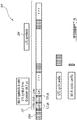
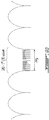
- Figure 2A shows a time-frequency diagram 80 of a set of LTE sub-channels (only a subset shown) used in a channel of the LTE RAN 10 of Figure 1 .
- each LTE subcarrier L-SC 1-M is modulated using varying levels of QAM modulation, e.g. QPSK, QAM, 64QAM or possibly higher orders depending on signal quality.
- QAM modulation e.g. QPSK, QAM, 64QAM or possibly higher orders depending on signal quality.
- Each OFDM symbol 82 is therefore a linear combination of the instantaneous signals on each of the sub-carriers L-SC 1-M in the channel. Because data is transmitted in parallel rather than serially, LTE symbols 82 are generally much longer than symbols on single carrier systems of equivalent data rate.
- each LTE symbol 82 is 66.7 microseconds ( ⁇ s) long and is preceded by a 4.7 ⁇ s cyclic prefix (CP) (not shown), which is used to reduce Inter-symbol Interference (ISI).
- CP cyclic prefix
- the total symbol length (including the CP) is 71.4 ⁇ s.
- Wi-Fi systems operate (mostly) indoors, usually from low power APs designed to cover ranges up to 50 or 100 meters.
- the resulting coherence bandwidth of the channel is large, as the delay spread (e.g. the impulse response of the channel) is usually very short, typically less than 500 nanoseconds (ns).
- ns nanoseconds
- Wi-Fi systems use wider 312.5 KHz sub-channels.
- Figure 2B shows a time-frequency diagram 90 of a set of Wi-Fi sub-channels (only a subset shown) used in a channel of the WLANs 20, 30 of Figure 1 .
- CP 0.8 ⁇ s cyclic prefix
- one base OFDM system (denoted as OFDM1) configured to transmit information using its defined set of (base) subcarriers to also be configured to encode subcarrier or symbol information of another OFDM system (denoted as OFDM2) in a way that such information can be decoded by receivers configured in accordance with that other system.
- an OFDM1 transmitter is configured to generate and transmit subcarrier and/or symbol information of any OFDM2 system that uses a subcarrier spacing larger (or substantially larger, e.g. by a factor of 10 or 20) than the OFDM1 subcarrier spacing.
- the OFDM1 transmitter is configured to generate and transmit subcarrier and/or symbol information of any OFDM2 system that uses a symbol duration smaller (or substantially smaller, e.g. by a factor of 10 or 20) than the OFDM1 symbol duration.
- the LTE subcarrier spacing is smaller than the Wi-Fi subcarrier spacing (which means the Wi-Fi symbol duration is smaller than the LTE symbol duration).
- the OFDM1 transmitter is configured to generate and transmit subcarrier and/or symbol information of any OFDM2 system that has a system bandwidth that is greater or equal to the OFDM1 system bandwidth.
- this may not be necessary.
- LTE can operate at multiple different system bandwidths (e.g. 5, 10, 15, 20 MHz) some of which may be smaller than the Wi-Fi system bandwidth
- an LTE transmitter can generally be configured to utilize the available spectrum in a way that is sufficient for Wi-Fi transmissions (see for example the implementations described below in relation to Figures 7A-B ).
- an LTE transmitter may encode and transmit Wi-Fi information in a way that it can be recovered by a Wi-Fi receiver.
- the LTE transmitter may also be configured to generate subcarrier and/or symbol information of yet other OFDM technologies.
- an LTE transmitter e.g. the access node 60 of Figure 1
- LTE subcarriers L-SC 1-M can use LTE subcarriers L-SC 1-M to generate 802.11 (e.g. Wi-Fi) subcarrier or symbol information that can be understood by Wi-Fi receivers, for example to reserve the channel for a certain duration, to indicate a transmission time associated with an on-going and/or upcoming symbol transmission or to create a carrier sense indication, for example, to cause Wi-Fi receivers and other radio technologies to consider the channel as busy.
- 802.11 e.g. Wi-Fi subcarrier or symbol information that can be understood by Wi-Fi receivers, for example to reserve the channel for a certain duration, to indicate a transmission time associated with an on-going and/or upcoming symbol transmission or to create a carrier sense indication, for example, to cause Wi-Fi receivers and other radio technologies to consider the channel as busy.
- the embodiments described below are primarily in relation to the generation of Wi-Fi subcarriers / symbol information in
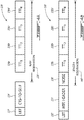
- FIG. 3 illustrates a timing diagram 100 showing an example of a symbol transmission by an LTE transmitting node (e.g. the access node 60 in the LTE RAN 10 of Figure 1 ), in accordance with the principles described herein.
- the access node 60 is configured to transmit Wi-Fi information, for example Wi-Fi header and/or packet data to indicate its current use of a (unlicensed) channel shared with devices in the WLANs 20, 30 and/or to reserve the channel for a certain amount of time (further details below).
- the Wi-Fi information is modulated by the access node 60 in the form of a set of one or more Wi-Fi symbols 110, 112, 114 (only three shown) and transmitted during the duration of one LTE symbol 102 (e.g.
- each Wi-Fi symbol 110, 112, 114 includes a respective CP 110a, 112a, 114a (e.g. 0.8 ⁇ s) and has a symbol duration (e.g. 3.2 ⁇ s) that conforms to the duration expected by devices in the WLANs 20, 30.
- the number of Wi-Fi symbols 110, 112, 114 is designed to fit into one LTE symbol duration 102 (e.g. after an LTE symbol preamble or CP 102a) but in other implementations, the number of Wi-Fi symbols 110, 112, 114 is substantially less than one LTE symbol duration 102.
- the access node 60 uses up to sixteen Wi-Fi symbols 110, 112, 114 in a 66.7 ⁇ s LTE symbol time duration. In yet other implementations, the access node 60 uses some of the Wi-Fi symbols 110, 112, 114 for Wi-Fi header data and the rest for Wi-Fi packet or frame data, the size of which depends on the Wi-Fi modulation rate used. In yet other implementations, the Wi-Fi symbols 110, 112, 114 are organized in multiple sets to span over multiple LTE symbol durations where each set is configured to fit in the duration of one LTE symbol. In yet other implementations, the first Wi-Fi symbol set is preceded by an LTE CP (e.g.
- Wi-Fi symbols 110, 112, 114 shown in Figure 3 represent one particular type of Wi-Fi symbols that can be used (e.g. for Wi-Fi data transmissions). However, it is important to note that depending on the implementation and the type of Wi-Fi transmission desired, the principles described herein also equally apply to other types of Wi-Fi symbols. For example, short and long Wi-Fi symbols such as those defined for Short Training Fields (STFs) and Long Training Fields (LTFs) could be used.
- STFs Short Training Fields
- LTFs Long Training Fields
- the Wi-Fi symbols may or may not be transmitted with a CP and may have time duration that is different from the time duration of the Wi-Fi symbols 110, 112, 114 (e.g. other 3.2 ⁇ s). Other possibilities exist for the Wi-Fi symbols 110, 112, 114.
- the Wi-Fi information contained in the Wi-Fi symbols 110, 112, 114 is to reserve the channel for the LTE transmission.
- the Wi-Fi information may be indicative of a transmission time, length, type associated with and/or a channel reservation time necessary for transmitting the Wi-Fi symbols 110, 112, 114, the LTE symbols 104 or a combination of both.
- the access node 60 generates Wi-Fi symbols 110, 112, 114 to contain a Wi-Fi header or a Clear-To Send (CTS) packet such as a "CTS-to-Self' packet to reserve the channel with a "virtual carrier sense", enabling devices in the WLANs 20, 30 to receive this header / packet information down to -82 dBm or lower and refrain from transmitting until after the LTE transmission (e.g. the LTE symbols 104) has been sent.
- CTS Clear-To Send
- the access node 60 can apply the same (LTE) processing functions such as filtering, PAR, digital pre-distortion, PSD management, RMS power control, etc., to the generation and transmission of both the Wi-Fi symbols 110, 112, 114 and the LTE transmission 104 which follows.
- LTE Long Term Evolution
- Wi-Fi header and/or packet data may be used for different applications. Also, depending on the application, the Wi-Fi header and/or packet data transmission does not necessarily need to be preceded by or followed by an LTE transmission. For applications other than channel reservation for example, the Wi-Fi information can be transmitted as a stand-alone transmission.
- the access node 60 may also use Wi-Fi symbols 110, 112, 114 to send PROBE REQUEST packets to detect nearby Wi-Fi APs.
- the access node 60 uses the Wi-Fi symbols 110, 112, 114 to send disassociation or de-authentication packets to Wi-Fi Stations (clients) in an attempt to move them to the LTE RAN 10.
- the access node 60 can use to Wi-Fi symbols 110, 112, 114 to send other types of Wi-Fi packets or frames including for example NULL packets, Wi-Fi sounding packets, LWA packets, Point Coordination Function (PCF) beacons, etc.
- the access node 60 instead of transmitting only Wi-Fi information or only LTE information at any given time, the access node 60 can be configured to transmit both Wi-Fi and LTE information concurrently. This will be explained below in greater detail starting with Figures 7A-B .
- the LTE symbol transmission is shown as a series of Transmission Time Intervals (TTIs) 126a-d and 138a-d which, in this example, are 1 millisecond (msec) each in duration.
- TTIs Transmission Time Intervals
- 138a-d Transmission Time Intervals
- Each of the Wi-Fi transmissions 124, 134 has a duration that fits within one LTE symbol but as noted above, the Wi-Fi transmissions 124, 138 may span multiple LTE symbols in other implementations.
- a Wi-Fi CTS-to-Self packet 124 is used to reserve the channel for TTIs 126a-d (only four shown) while in the example of Figure 4B , a Wi-Fi header 134 is used for TTIs 138a-d.
- each of the CTS-To-Self packet 124 and header 134 contains a channel reservation indication indicating an amount of time during which the access node 60 intends to use the channel.
- the reservation indication prevents listening devices (e.g. devices in the WLANs 20, 30 that have received and demodulated the indication) to perform any transmission until the reservation time has expired.
- the channel reservation indication is a Network Allocation Vector (NAV) indication in the CTS-To-Self packet 124.
- the NAV indication is a NAV timer value defining how long the channel will be reserved.
- the NAV timer value is indicative of a time required to transmit the CTS packet, the LTE TTIs 126a-d (e.g. NAV reservation time 128) and/or a combination thereof.
- the NAV timer value is an end time of the LTE TTI 126a-d transmission.
- the channel reservation indication is included in a different field of the CTS-to-Self packet 124.
- any packet data or any field of a Wi-Fi packet may be used for the channel reservation indication.
- the channel reservation indication is a value indicative of any one of a transmission length, time or type or a channel reservation time associated with the CTS-to-Self packet 124, the LTE symbols and/or both. Other possibilities exist for the channel reservation indication.
- the channel reservation indication is a length reservation indication or other control data in the Wi-Fi header 134 representing an octet count associated with the LTE TTIs 138a-d.
- the length reservation indication (or control data) is a time duration required for transmitting the Wi-Fi header 134, the LTE TTIs 138a-d (e.g. length reservation time 140) and/or a combination thereof.
- the length reservation indication is an end time of the LTE TTI 138a-d transmission.
- the Wi-Fi header 134 and the LTE TTIs 138a-d may be viewed as a combined packet transmission 130 where the LTE TTIs 138a-d (and possibly other information) form the packet data payload with a length that corresponds to the length reservation indication.
- Wi-Fi receivers e.g. devices in WLANs 20, 30
- LTE receivers e.g. the access node 60
- LTE receivers e.g. the access node 60
- the Wi-Fi header may be unrecoverable.
- the Wi-Fi and LTE transmissions are either contiguous or non-contiguous transmissions.
- the access node 60 may, in some implementations, initiate the LTE transmission immediately after completing the Wi-Fi transmission or alternatively, wait after a certain delay (e.g. as in Figure 4A ). In other implementations such as the example shown in Figure 4B , the access node 60 transmits noise (or some RF power) during that delay to maintain the transmit power envelope and prevent Wi-Fi devices to assume the channel is free.
- the access node 60 may continue to use the channel beyond the time duration or end time indicated by the channel reservation indication.
- the access node 60 may also be configured for an additional transmission following TTIs 126a-d or TTIs 138a-d.
- the additional transmission may be an additional set of LTE TTIs or some other transmission (e.g. a Wi-Fi transmission) and is contiguous with the preceding TTIs 126a-d, 138a-d to prevent Wi-Fi devices from transmitting during the additional transmission.
- the channel reservation indication indicates how long the channel is reserved for the LTE TTIs 126a-d, 138a-d but not for the additional transmission.
- the access node 60 performs a channel availability check using a contention-based method, for example Listen-Before-Talk (LBT) 122, 132 to determine whether another transmission is in progress in the channel or band used. This determination may be based on the detection of a carrier wave, signal or energy in the channel or band of interest (e.g. with a -62 dBm threshold). If during that time, a carrier or energy is detected in the band or channel of interest (in another fully or partially overlapping channel or band), the access node 60 waits for the transmission in progress to finish before initiating its own transmission.
- LBT Listen-Before-Talk
- the access node 60 (immediately) transmits either the CTS-To-Self packet 124 or header information 134 and completes the subsequent LTE transmission (TTIs 126a-d or 138a-d).
- FIG 5 illustrates an example of a Physical Layer Convergence Protocol (PLCP) Protocol Data Unit (PPDU) 150 that includes the CTS-To-Self packet 124 shown in Figure 4A in accordance with the principles described herein.
- the CTS-to-Self packet denoted as 170
- PLCP Service Data Unit field 156 of the PPDU 150 which also includes a preamble 152 and a header 154 (collectively herein referred to as header) as well as tail and pad fields 158, 160.
- the CTS frame 170 includes a frame control field 172 that specifies the type of frame 170 (in this case a CTS-To-Self frame), a duration field 174 to specify a NAV timer value, a Receiver Address (RA) field 176 which is set to the Transmitter Address for a CTS-To-Self packet and a Frame Check Sequence (FCS) field 178 which specifies an error-correcting code for the CTS packet 170.
- RA Receiver Address
- FCS Frame Check Sequence
- eleven Wi-Fi symbols are required to transmit the CTS-To-Self packet 170 (as included in a PPDU 150) for a total transmission length of 44 ⁇ s which fits into a 71.4 or 83 ⁇ secLTE symbol.
- FIG 6A illustrates an example of a format for the Wi-Fi header 134 shown in Figure 4B in accordance with the principles described herein.
- the Wi-Fi header 134 is a PLCP header 208 which includes a preamble 202 and a Signal field (SIG) 204 (collectively herein referred to as header data) contains a channel reservation indication (in the SIG 204) to reserve the channel for a certain period of time.
- the channel reservation indication is set in a length field 214 as an octet count which is indicative of the amount of data to follow in a data field 206.
- the channel reservation indication in the length field 214 is indicative of the time required to transmit or an end transmission time for the data (e.g. up to 5 msec).
- the data contained in the data field 206 and the PLCP header 208 are shown as a combined transmission 200 where the data field length corresponds to the channel reservation indication contained in the SIG 204.
- the PLCP header 208 and the data field 206 may be sent as two separate transmissions (e.g. non-contiguous transmissions).
- the data includes LTE symbols (e.g.
- the data may include additional or other information such as Wi-Fi symbols and/or a random transmission (e.g. noise 136).
- additional or other information such as Wi-Fi symbols and/or a random transmission (e.g. noise 136).
- the data in the data field 206 may also be followed by an additional transmission, such as an additional set of LTE TTIs or some other transmission (e.g. a Wi-Fi transmission).
- the SIG 204 also includes the rate field 210 that specifies a modulation rate for the data in the data field 206, a reserved field 212, a parity field 216, a tail field 218 and a service field 220.
- the tail field 218 is set to a value indicative of a type of symbols or OFDM associated with the data in the data field 206 (e.g. in this case an LTE type).
- the tail field 218 is set of a first value when LTE symbols are present in the data field 206 and a different value when non-LTE symbols (e.g. Wi-Fi symbols) are included).
- setting the tail field 218 to a value indicative of the presence of LTE symbols in the data field 206 notifies listening devices (devices configured to receive and demodulate the PLCP header 208) that the data field 206 contains symbols of a different OFDM type (e.g. LTE symbols).
- this indication is an OFDM indication and may be included in another field (other than the tail field 218 or the SIG 204) at the same or different layer.
- the OFDM indication is included in a MAC layer protocol field, such as the Frame Control Field which contains bits (e.g. b0 and b1) normally used to specify an associated protocol.
- This OFDM indication may represent an OFDM type or mode or an OFDM parameter associated with the data in the data field 206 such as symbol duration, CP duration, number of subcarriers, subcarrier spacing, subcarrier modulation formats, subcarrier frequencies, etc.
- Figure 6B shows other format examples for the Wi-Fi header 134 shown in Figure 4B that can be used by the access node 60 to reserve a channel according to the principles described herein.
- transmission 240 includes a Legacy (L) Short Training Field (STF) 242, a Legacy (L) Long Training Field (LTF) field 244, and a Legacy (L)-SIG 246 that contains a channel reservation indication to reserve the channel for the data (e.g. LTE symbols or Wi-Fi symbols) to be transmitted in data field 248.
- STF Short Training Field
- LTF Long Training Field
- transmission 250 includes an L-STF 252, an L-LTF 254, an L-SIG 256, a High Throughput (HT)-SIG field 258, an HT-STF 260, an HT-LTF 262 and a data field 264.
- Either the L-SIG 246 or the HT-SIG 258 is configured to contain a channel reservation indication to reserve the channel for the data to be transmitted in the data field 264.
- transmission 270 includes an L-STF 272, an HT SIG 274, an HT-STF 276, an HT-LTF 278 and a data field 280.
- the HT-SIG 274 is configured to contain a channel reservation indication to reserve the channel for the data to be transmitted in the data field 280.
- the data in the data field 248, 264, 280 includes LTE symbols (e.g. LTE TTIs 138a-d in Figure 4B ) but in other examples, the data may include additional or other information such as Wi-Fi symbols and/or a random transmission (e.g. noise 136). Other possibilities exist for the data in the data field 248, 264, 280. As noted above, the data in the data field 248, 264, 280 may also be followed by an additional transmission, such as an additional set of LTE TTIs or some other transmission (e.g. a Wi-Fi transmission).
- the channel reservation indication used is a length value included in a SIG field
- any control data or field in the Wi-Fi header 134 can be used for the channel reservation indication.
- the channel reservation indication is a value indicative of any one of a transmission length, time or type or a channel reservation time associated with the Wi-Fi header 134, the data in the data field LTE symbols and/or both. Other possibilities exist for the channel reservation indication.
- a Wi-Fi header or preamble transmission (such as the Wi-Fi header 134 shown in Figure 4B ) spanning over one entire LTE symbol duration (e.g. 66.7 ⁇ s) may be used to reserve a channel.
- a series of 3 Wi-Fi headers each including a set of LTF, STF and SIG fields plus an additional STF field is used.
- the Wi-Fi headers may be preceded by an LTE symbol preamble or CP (e.g. CP 102a of Figure 3 ). Note that other combinations of Wi-Fi header information may be used for the transmission, including for example:
- the Wi-Fi header transmission described above is configured to fit within one LTE symbol time. However, depending on the application, the Wi-Fi header transmission may span multiple LTE symbols. Also, the Wi-Fi header transmission does not necessarily need to be preceded by or followed by an LTE transmission. For applications other than channel reservation for example, it may be transmitted as a stand-alone transmission.
- the examples described above show that the Wi-Fi and LTE transmissions are sequential. However, in some implementations, it may be desirable or necessary to transmit Wi-Fi and LTE information concurrently. In those cases, the access node 60 maps or assigns different subsets of the available OFDM subcarriers to the different OFDM signals in a way that the data contained therein can be transmitted at the same or during an overlapping time interval.
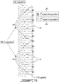
- Figure 7A illustrates an example of how an OFDM1 transmitter (e.g. the access node 60) configured to use OFDM1 subcarriers can partition the available subcarriers, denoted here as 281 1-M , into two subsets which can then be used for generating and/or transmitting OFDM signals carrying information associated with different OFDM communication protocols at the same time.
- a first subset of OFDM1 subcarriers 282 is used for generating and/or transmitting a first OFDM signal (e.g. a first OFDM1 signal) containing data associated with a first OFDM communication protocol (denoted as OFDM1).
- a second subset of OFDM1 subcarriers 284 is used for generating and/or transmitting a second OFDM signal (e.g. a second OFDM1 signal) containing data associated with a second OFDM communication protocol (denoted as OFDM2) but which, conventionally, would be generated and transmitted using OFDM2 subcarriers (shown in Figure 7A as 286 1-3 ).
- a second OFDM signal e.g. a second OFDM1 signal
- OFDM2 subcarriers shown in Figure 7A as 286 1-3 .
- an OFDM1 transmitter can generate and/or transmit the first and second OFDM1 signals because they both use OFDM1 subcarriers.
- the first OFDM1 signal is generated by mapping a predetermined OFDM1 signal (e.g.
- the first and second subsets 282, 284 are formed of a number of interleaved groups of contiguous OFDM1 subcarriers (four shown for the first subset (282 A-D ) and three for the second subset (284 A-C )). However, it is important to note the other possibilities exist. For example, depending on the number of OFDM protocols to support, a different number of subsets 282, 284 may be used.
- subcarriers in each subset 282, 284 may be contiguous or non-contiguous (in frequency) and the number and/or placement of subcarriers contained in each subset 282, 284 may vary, for example, depending on the nature of the OFDM signals and/or data they contain.
- the subcarriers for the second subset 284 are selected such that there is sufficient overlap in frequency with the OFDM2 subcarriers to ensure the second OFDM1 signal carrying the OFDM2 information can be recovered by the intended OFDM2 receiver(s).
- the number of OFDM1 subcarriers overlapping with OFDM2 subcarriers may vary.
- the subcarriers for the second subset 284 include at least one subcarrier that overlaps in frequency with an OFDM2 subcarrier.
- each of the subcarrier groups 824 A-C include at least one subcarrier that overlaps with the main lobe of an OFDM2 subcarrier 286 1-3 .
- the second subset 282 only includes subcarriers that overlap in frequency with an OFDM2 subcarrier (or a main lobe thereof).
- the second subset 284 includes some of the OFDM1 subcarriers that normally are part of the frequency resources defined to be used for the predetermined OFDM1 signal but happen to overlap with an OFDM2 subcarrier (of a main lobe thereof).
- some of the OFDM1 subcarriers defined for the predetermined OFDM1 signal but which overlap with an OFDM2 subcarrier are not mapped or modulated with the predetermined OFDM1 information but are used instead to transmit the OFDM2 signal containing OFDM2 information.
- the OFDM1 subcarriers defined for the predetermined OFDM1 signal which also happen to overlap with an OFDM2 subcarrier (or a main lobe thereof) may instead be "blanked” or “muted” i.e. not included in any of the first or second subsets 282, 284 and therefore not used for transmitting either the first or second OFDM1 signals. All of these possibilities may be referred to as "puncturing" of the predetermined OFDM1 signal. Other ways of puncturing the predetermined OFDM1 signal are possible.
- FIG 7B illustrates a more specific example where an LTE transmitter (e.g. the access node 60) configured can partition the LTE subcarriers available across the system bandwidth into two subsets, also denoted here as 282, 284, which can then be used for generating and/or transmitting a predetermined Wi-Fi signal (e.g. the CTS-to-Self packet 124 or Wi-Fi header 134 of Figure 4B ) concurrently with a predetermined LTE signal (in this example a DRS signal) that may need to be transmitted within a certain time window and /or with a certain periodicity.
- a predetermined Wi-Fi signal e.g. the CTS-to-Self packet 124 or Wi-Fi header 134 of Figure 4B
- a predetermined LTE signal in this example a DRS signal
- the ability to transmit DRS and Wi-Fi signals at the same time may be beneficial in implementations where the Wi-Fi transmission overlaps in time with a required DRS transmission.
- the DRS signal which is employed for providing Radio Resource Management (RRM) functionality for LAA operation, was introduced in 3GPP (Release 12) to support secondary cell (“SCell") activation and deactivation. SCells that are not activated for any UEs may generally be turned off except for periodic DRS transmissions.
- a conventional DRS transmission is allocated predetermined or defined Resource Elements (RE) across the system bandwidth and typically includes any combination of the following signals:
- the information carried by the DRS typically contains cell and/or PLMN identification as well as other control information that may be required for proper LAA operation e.g. to enable UEs to identify a detected cell and/or the operator of the cell.
- the DRS is transmitted in DRS occasions that may have a periodicity of 40, 80 or 160 msec. When LBT is applied to DRS transmissions, there will be some instances where the DRS cannot be transmitted periodically as it may in licensed spectrum. According to 3GPP standards, the DRS cannot exceed 1msec in duration (i.e.
- a typical DRS transmission is defined to include CRS signals in symbols 0, 1 and 4 of slots 0 and 1 (using every 3 rd RE), PSS/SSS signals in symbols 5/6 of slot 0 (using all REs), and Non-Zero Power (NZP) -CSI-RS signals in symbols 2, 3 of slot 1 (using every 12 th RE). All other REs may be used for CSI-RS signals (ZP or NZP), and/or control (e.g. PDCCH) or user (DPSCH) transmissions.
- DMTC Discovery Measurement Timing Configuration
- the available LTE subcarriers are partitioned into two subsets, 282, 284.
- the first subset 282 includes the subcarriers necessary to transmit and generate a predetermined CRS signal (i.e. subcarriers corresponding to every 3 rd RE) while the remainder of the subcarriers are grouped into the second subset 284 and used for a Wi-Fi transmission (e.g. the CTS-to-Self packet 124 or Wi-Fi header 134 of Figure 4B ).
- some or all of the LTE subcarriers 290 that overlap in frequency with a Wi-Fi subcarrier 286 (or a main lobe thereof) are included in the second subset 284.
- the LTE subcarriers 290 that correspond to defined CRS REs 292 and that overlap with a Wi-Fi subcarrier 286 are included in the second subset 284.
- the overlapping subcarriers 290 defined to be used for CRS REs 292 are not mapped or modulated with CRS information but are instead used for transmitting Wi-Fi information.
- the CRS REs 292 using an overlapping LTE subcarrier 290 are punctured.
- this may be beneficial to improve the Wi-Fi signal quality required, reduce the level of distortion that can be tolerated and/or improve the probability of successful detection by a Wi-Fi receiver. It is understood that depending on the level of distortion and/or performance degradation that can be tolerated in the CRS signal, any number of CRS REs may be punctured, not necessarily only those that might overlap with a Wi-Fi subcarrier.
- the CRS signal can be fully punctured if the channel is stationary or partially punctured (e.g. every second CRS RE) if the channel estimation by the UEs could be impaired if CRS is not properly detected.
- the CRS signal can be fully punctured if the coherence time of the channel (i.e. the time over which the amplitude fading is less than a defined threshold) exceeds the duration of an LTE slot (i.e. 0.5 msec) or a configurable fraction ⁇ (e.g. a value between 0 and 1).
- the configurable fraction a can be set by the LTE transmitter (e.g. the access node 60) or higher layer network nodes.
- some or all of the overlapping subcarriers 290 defined to be used for CRS REs 292 may instead be kept in the first subset 282. This may be beneficial in some of those implementations to improve the CRS signal quality required, reduce the level of distortion and/or improve the probability of successful CRS detection by an LTE receiver (for example to reduce the degradation of performance of channel estimation, enable proper RRM measurements, time/frequency tracking, etc.).
- LTE subcarriers 290 defined to be use for CRS REs 292 are included in the second subset 284, instead of mapping the CRS signal only to LTE subcarriers in the first subset 282, the CRS signal is also mapped to some or all of the LTE subcarriers in the second subset 284 (e.g. those that are normally used or defined for CRS REs) but at a reduced power level (lower than a power level used for mapping the CRS signal to subcarriers in the first subset 282). In some of those implementations, this may be beneficial to reduce the impairment to the detection of the Wi-Fi transmission at a Wi-Fi receiver.
- the Wi-Fi signal is also mapped to LTE subcarriers in the first subset 282 (e.g. those that overlap with a Wi-Fi subcarrier) but at a reduced power level (lower than a power level used for mapping the Wi-Fi signal to the subcarriers in the second subset 284). In some of those implementations, this may be beneficial to reduce the impairment to the detection of the CRS signal at an LTE receiver.
- the LTE system bandwidth is at least equal or greater than the Wi-Fi system bandwidth (e.g. 20 MHz).
- the second subset 284 may only include LTE subcarriers that correspond to the lower frequency components of the Wi-Fi transmission (i.e. the higher frequency components of the Wi-Fi transmission are truncated and not transmitted). For example, if the LTE system bandwidth is 10 MHz, the second subset 284 only includes LTE subcarriers that correspond to the Wi-Fi frequency components below 10 MHz (thereby truncating the frequency components above 10 MHz up to 20 MHz).
- the second subset 284 may only include LTE subcarriers that correspond to the higher frequency components of the Wi-Fi transmission (i.e. the lower frequency components of the Wi-Fi transmission are truncated and not transmitted). Other possibilities exist for the second subset 284.
- an OFDM1 transmitter may, in other implementations, use OFDM1 subcarriers which are located in unused portions of the OFDM2 system bandwidth (and hence orthogonal to subcarriers in the used portion) to transmit additional OFDM1 information.
- OFDM1 subcarriers typically span the entire Wi-Fi system bandwidth (e.g.
- the Wi-Fi system bandwidth is limited by the IEEE 802.11 specified transmit spectral mask, defined as fc ⁇ 9 MHz (or 18 MHz wide) for a 20 MHz wide channel. For a 40 MHz wide channel, the IEEE 802.11 standard defines the transmit spectral mask as fc ⁇ 19 MHz (or 38 MHz wide).
- Transmit spectral masks are also defined for 80 and 160 MHz wide channels.
- the subcarriers in the band edges are not employed to allow for sufficient attenuation of the transmitted signals' out-of-band emissions, for example, to accommodate filters in OFDM receivers designed without a sharp roll-off.
- some subcarriers in the Wi-Fi band may not be employed, even though they are part of the designed Wi-Fi system bandwidth.
- non-Wi-Fi OFDM transmitters e.g. an LTE transmitter
- This may be particularly useful for receivers designed (e.g. with tighter band edge filtering requirements) such that they are capable of recovering data transmitted in unused portions of the Wi-Fi system bandwidth as described herein and still meet the band edge emission requirements.
- Figure 8 shows an example frequency diagram of a 20 MHz 802.11a Wi-Fi channel system bandwidth that includes unused portions 294 A , 294 C at the lower and upper edges as well as in a middle portion 294 B where the single 312.5 kHz Wi-Fi DC null subcarrier is normally set to zero.
- the amount of free, unused bandwidth at each of the lower and upper edges is 1.71875 MHz, which represents half of (20 MHz - 53 x 312.5 kHz).
- 802.11n/ac supports an additional 1.09375 MHz of unallocated or unused spectrum at the edge of each channel band.
- the size and location of unused spectral portions may be different depending on the type of OFDM2 communication protocol and the size of the channel (e.g. 20, 40, 80, 160 MHz), the size and location of unused spectral portions may be different.
- an LTE transmitter operating in the same or an overlapping system bandwidth can therefore generate and/or transmit LTE signals using only those LTE subcarriers which are located in any one of the spectral portions 294 A-C not utilized or occupied by Wi-Fi subcarriers but located within the LTE system bandwidth.
- This approach applies irrespective of whether the LTE transmitter uses the entire Wi-Fi system bandwidth.
- a smaller LTE spectrum e.g. 18 MHz
- the 15 kHz LTE subcarrier spacing is substantially smaller than the 312.5 kHz Wi-Fi subcarrier spacing, a good number of LTE subcarriers orthogonal to the Wi-Fi subcarriers can be used.
- a narrower LTE subcarrier spacing (for example, of 3.75 kHz) may be employed for 3GPP Narrowband Internet of Things (loT) implementations, and future 3GPP 5G New Radio (NR) technology specifications may also include other subcarrier spacings such as 30 or 60 kHz, all of which are considerably less than the 312.5 kHz being employed in Wi-Fi.
- an LTE transmitter operating in the same or an overlapping system bandwidth can advantageously generate and transmit additional LTE data independently of whether the Wi-Fi channel is available or not. Also, as will be explained below in greater detail, if the Wi-Fi channel is busy, the LTE transmitter can limit its LTE transmissions to only use the LTE subcarriers in non-utilized portion(s) of the Wi-Fi system bandwidth. Alternatively, or additionally, if the Wi-Fi channel is idle, the LTE transmitter can be configured to operate as described above i.e.
- LTE and Wi-Fi signals concurrently (by partitioning the LTE available subcarriers into first and second subsets 282, 284) or in sequence (e.g. by using the LTE subcarriers to generate and/or transmit a Wi-Fi signal to reserve the channel for a subsequent LTE transmission).
- the number of LTE and Wi-Fi subcarriers used can be such that the LTE and/or Wi-Fi transmissions can be performed over either the entire LTE system bandwidth or limited to the Wi-Fi system bandwidth.
- the data can include one or more fields of the Wi-Fi transmission so that LTE receivers can be made aware of the concurrent Wi-Fi transmission and/or of an upcoming LTE transmission.
- the additional LTE data could include the source and destination MAC addresses and duration field of the CTS packet.
- the additional LTE data can be predetermined and include one or more information fields or elements of a Wi-Fi header or CTS packet to be sent concurrently over (used portions of) the Wi-Fi system bandwidth as described above.
- the additional data may include additional information specific to the LTE transmitter, such as a cell identification (ID), a location, or one or more connected network(s).
- ID a cell identification
- Figure 9A shows a frequency diagram example where 114 LTE subcarriers of 15 kHz located in non-utilized edge portions of a Wi-Fi 20 MHz channel are used to generate and/or transmit LTE signals.
- Figure 9A only shows the LTE subcarriers in upper edge portion 294c but although not shown, it is understood that a similar number of additional LTE subcarriers could be located in the lower edge portion 294 A as well as up to 20 additional LTE subcarriers could be used in the middle portion 294 B (normally the Wi-Fi DC Null Wi-Fi subcarrier spacing).
- the LTE subcarriers in the non-utilized portions 294 A-C are included in the first subset 282 and the LTE subcarriers located within the portion of the Wi-Fi band normally occupied by Wi-Fi subcarriers (i.e. a utilized portion)) are included in the second subset 284 and used to generate and/or transmit Wi-Fi signals as described above in relation to Figures 7A-B .
- the LTE transmitter is equipped with Wi-Fi circuitry (e.g. a Wi-Fi module or transceiver)
- Wi-Fi circuitry e.g. a Wi-Fi module or transceiver
- some of the subcarriers used in the second subset 284 may instead be replaced with LTE subcarriers and allocated to the first subset 282 (in addition to LTE subcarriers located in the unused portions 294 A-C of the Wi-Fi band, leaving even more bandwidth to additional LTE data.
- FEC Forward Error Correction
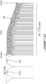
- Figure 9B shows another frequency diagram example where the power level or amplitude of the LTE subcarriers in the upper edge portion 294c has been adjusted to meet a 20 MHz power spectral density mask 295 that might be imposed on transmissions within and around the Wi-Fi system bandwidth.
- the upper edge of the transmit mask 295 is flat up to +9 MHz from the channel center, then drops 20 dBr over the next 2 MHz to +11 MHz from the channel center.
- Wi-Fi receivers can handle high levels of (first) Adjacent Channel Interference (ACI) from channels which are ⁇ 20 MHz from the active 20 MHz Wi-Fi channel, and higher levels of (second) ACI from channels which are ⁇ 40 MHz from the active 20 MHz Wi-Fi channel.
- ACI channels are sufficiently far enough away from the active 20 MHz channel, that filtering techniques can be applied to mitigate the high power interference signals which are not following the OFDM subcarrier spacing in the 20 MHz Wi-Fi channel.
- Figures 9C and 9D show other frequency diagram examples where the power level of all of the LTE subcarriers in the upper edge portion 294c and the middle portion 294 B has been lowered relative to a power level of the Wi-Fi subcarriers so that the energy from the additional LTE subcarriers does not significantly affect the Wi-Fi OFDM receiver.
- Wi-Fi receivers require a Signal-to-Interference-plus-Noise-Ratio (SINR) of 5 dB (e.g.
- SINR Signal-to-Interference-plus-Noise-Ratio
- the total relative power of the injected LTE subcarriers should be lower than the desired Wi-Fi SINR by 10 dB so as not to affect the Wi-Fi receive sensitivity by more than 0.1 dB.
- the additional LTE subcarriers represent less than 10% of the Wi-Fi channel bandwidth (or less than 2 MHz) and as such, their total relative power is already lower by 10 dB.
- the total relative power of the additional LTE subcarriers is reduced by the desired Wi-Fi SINR.
- the power level of the LTE subcarriers is reduced by 5 dB while the power level for high modulation rate (e.g. 64 QAM) MIMO transmissions, may require a further reduction (e.g. 30 dB).
- the LTE subcarriers are transmitted at the same or even higher power than the Wi-Fi carriers.
- the LTE transmitter configuration may include two separate and independent physical layers (LTE and Wi-Fi), with different ASIC components and/or circuitry that reflect differences in for example, the symbol durations, cyclic prefix durations, number of subcarriers, subcarrier spacing, subcarrier modulation formats, subcarrier frequencies, or any one of numerous MAC layer differences, but it does not preclude that a common ASIC or other hardware circuitry can be configured to support both OFDM technologies.
- LTE and Wi-Fi two separate and independent physical layers
- ASIC components and/or circuitry that reflect differences in for example, the symbol durations, cyclic prefix durations, number of subcarriers, subcarrier spacing, subcarrier modulation formats, subcarrier frequencies, or any one of numerous MAC layer differences, but it does not preclude that a common ASIC or other hardware circuitry can be configured to support both OFDM technologies.
- FIG. 10A and 10B there is shown two different block diagram examples of an OFDM transmitter 300, 350 of a first (or base) OFDM technology, denoted as OFDM1 (e.g. a 3GPP or LTE technology), which, in addition to being configured to use some or all of M base subcarriers for OFDM1 transmissions, is also configured to transmit subcarrier or symbol information of another OFDM technology, denoted as OFDM2 (e.g. a Wi-Fi technology), using some or all of the M subcarriers.
- OFDM1 e.g. a 3GPP or LTE technology
- OFDM2 e.g. a Wi-Fi technology
- the OFDM1 transmitters 300, 350 operate in a similar fashion but as will be explained below in greater detail, implementations of the OFDM1 transmitter 300 use time-domain interpolation to generate the OFDM2 information (e.g. using a Time-Domain (TD) Interpolator 314) while implementations of the OFDM1 transmitter 350 use frequency-domain interpolation instead (e.g. using a Frequency-Domain Interpolator 364).
- TD Time-Domain
- the OFDM1 transmitter 300, 350 is configured to generate OFDM1 signals carrying OFDM1 or OFDM2 information and to transmit the signals generated concurrently or in sequence.
- the first and second OFDM1 signals are transmitted concurrently over an OFDM2 system bandwidth (e.g. a Wi-Fi system bandwidth), where, for example, the second OFDM1 signal is transmitted over portion(s) of the OFDM2 system bandwidth normally used or occupied by OFDM2 subcarriers while the first OFDM1 signal is transmitted over non-utilized portion(s) of the OFDM2 system bandwidth.
- the first OFDM1 signal may be generated by mapping a first predetermined OFDM1 signal to a first subset of the available OFDM1 subcarriers (e.g.
- the second OFDM1 signal may be generated by mapping a second predetermined OFDM2 signal (e.g. a CTS-to-Self packet or Wi-Fi header) to a second subset of the OFDM1 subcarriers (e.g. OFDM1 subcarriers located in the used portions of the OFDM2 system bandwidth).
- the first OFDM1 signal may include parameters or data indicative of the concurrent OFDM2 transmission so that OFDM1 receivers can be made aware of the concurrent OFDM2 transmission and/or any subsequent OFDM1 transmissions.
- the OFDM1 transmitter 300, 350 may be additionally configured to transmit a subsequent (e.g. a third) OFDM1 signal using the M OFDM1 subcarriers.
- the OFDM2 information transmitted and subsequent OFDM1 signal transmission may be contiguous or non-contiguous.
- the OFDM1 transmitter 300, 350 may use the OFDM2 transmission to encode various types of OFDM2 related information for various purposes, including for example to reserve a channel for a certain duration, to indicate a transmission time associated with the OFDM2 and/or the subsequent OFDM1 signal transmission or to create a carrier sense indication, for example, to cause OFDM2 receivers to consider the channel as busy.
- the OFDM2 transmission includes Wi-Fi header data and/or Wi-Fi packet data and the subsequent OFDM1 signal transmission includes LTE data (or LTE TTIs) and the Wi-Fi header or packet data in the OFDM2 transmission is indicative of a transmission length, a transmission time, a transmission type and/or a channel reservation time associated with the Wi-Fi header/packet data, the LTE data or a combination of both.
- the OFDM1 transmitter 300 has an OFDM1 transmission chain 302, an OFDM1 subcarrier mapping unit 308, an OFDM1 Inverse Fast Fourier Transform (IFFT) unit 304 and an OFDM1 RF unit 306 (e.g. DAC, mixer, and PA) which, in combination, are configured to generate and transmit a first OFDM1 signal 320 via one or more antennas 307.
- the OFDM1 transmission chain 302 generates (i.e. converts) a serial OFDM1 symbol stream of Binary Phase Shift Keying (BPSK) or Quadrature Amplitude Modulation (QAM) data into M parallel streams.
- BPSK Binary Phase Shift Keying
- QAM Quadrature Amplitude Modulation
- a predetermined OFDM1 signal is modulated onto (some or all of) the M base OFDM1 subcarriers via the OFDM1 subcarrier mapping unit 308 to produce the first OFDM1 signal 320 which, after conversion into the time domain in the IFFT unit 304, is transmitted via the RF unit 306 and antenna 307.
- the OFDM1 transmitter 300 also includes circuitry that is configured to produce a second OFDM1 signal 322 to carry OFDM2 information for transmission via the antenna 307.
- the circuitry includes an OFDM2 signal generator 312 configured to generate an OFDM2 signal.
- the OFDM2 signal is a time-domain signal that contains predetermined or defined OFDM2 symbol information generated with, for example, N OFDM2 subcarriers.
- the circuitry further includes an OFDM2-OFDM1 Time-Domain (TD) interpolator 314 that interpolates in the time-domain the OFDM2 signal generated (further details below).
- TD Time-Domain
- the circuitry includes an OFDM1 signal memory 316 where the FDS signal is stored.
- the OFDM1 transmitter 300 determines that OFDM2 information needs to be transmitted, it generates the FDS dynamically (e.g. on the fly) using the signal generator 312 and TD interpolator 314 or simply reads the FDS signal from the signal memory 316 and routes it to the OFDM1 subcarrier unit 308.
- the OFDM1 subcarrier mapping unit 308 maps the FDS signal to (some or all of) the M OFDM1 subcarriers to produce the second OFDM1 signal 322 which is then coupled to the IFFT and RF units 304, 306 for transmission via the antenna 307.
- the circuitry may only include signal memory 316.
- the stored FDS signal is a predetermined or defined vector of OFDM1 (frequency-domain) subcarrier modulation values (e.g. a vector with M values) that includes values representative of predetermined or defined OFDM2 information.
- STF _ LTE _ SCs ⁇ 499 , ⁇ 415 , ⁇ 332 , ⁇ 249 , ⁇ 165 , ⁇ 82 , 85 , 168 , 252 , 335 , 418 , 502
- STF _ LTE _ SC _ Value ⁇ 13 / 6 * 1 + i , ⁇ 1 ⁇ i , 1 + i , ⁇ 1 ⁇ i , ⁇ 1 ⁇ i , 1 + i , ⁇ 1 ⁇ i , 1 + i , 1 + i , 1 + i , 1 + i , 1 + i , 1 + i , 1 + i , 1 + i , 1 +
- Each of the twelve LTE subcarriers identified above in the STF_LTE_SCs array by sequence number is set to a corresponding non-zero modulation value in the STF_LTE_SC_Value array.
- the twelve LTE subcarriers identified above are those that overlap with at least one Wi-Fi subcarrier (or a main lobe thereof) i.e. the Wi-Fi subcarrier(s) normally used to produce an STF.
- all other LTE subcarriers are set to a zero value (e.g. (0+0i)).
- LTF _ LTE _ SCs ⁇ 540 , ⁇ 519,499 , ⁇ 478 , ⁇ 457 , ⁇ 436 , ⁇ 415 , ⁇ 394 , ⁇ 374 , ⁇ 353 , ⁇ 332 , ⁇ 311 , ⁇ 290 , ⁇ 269 , ⁇ 249 , ⁇ 228 , ⁇ 207 , ⁇ 186 , ⁇ 165 , ⁇ 144 , ⁇ 124 , ⁇ 103 , ⁇ 82 , ⁇ 61 , ⁇ 40 , ⁇ 19 , 22 , 43 , 64 , 85 , 106 , 127 , 147 , 168 , 189 , 210 , 231 , 252 , 272 ,
- Each of the fifty-two LTE subcarriers identified above in the LTF_LTE_SCs array by sequence number is set to a corresponding non-zero modulation value in the LTF_LTE_SC_Value array.
- the fifty-two LTE subcarriers identified above in this example are those that overlap with at least one Wi-Fi subcarrier (or a main lobe thereof) i.e. the Wi-Fi subcarrier(s) normally are used to produce an LTF.
- all other LTE subcarriers are set to a zero value (e.g. (0+0i). Other possibilities exist for the LTE subcarrier modulation values.
- the OFDM1 transmitter 300 may be configured to transmit the first and second OFDM1 signals 320, 322 either at the same or at different times.
- the OFDM1 mapping unit 308 is configured to map the OFDM1 transmission chain output (e.g. the predetermined OFDM1 signal) to all of the M OFDM1 subcarriers.
- the OFDM1 mapping unit 308 is configured to map the FDS signal to all of the M OFDM1 subcarriers.
- a switch or other switching means may be used to route either the OFDM1 transmission chain output or the FDS signal into the OFDM1 subcarrier mapping unit 308 to selectively produce either the first or second OFDM1 signal 320, 322 so that they can be converted into the time domain in IFFT unit 304 (as time-domain signal 324) and transmitted via the RF unit 306 and antenna 307
- the OFDM1 transmitter 300 may include circuitry configured to generate the second OFDM1 signal as a time-domain signal.
- the circuitry may include the OFDM2 signal generator 312 and TD interpolator 314 configured to produce the second OFDM1 signal as a time-domain OFDM1 signal 326, TDS, to carry the OFDM2 information.
- the OFDM1 transmitter 300 when it determines that the OFDM2 information needs to be transmitted, the OFDM1 transmitter 300 generates and routes the TDS signal 326 into the OFDM1 RF unit 306 via a switch (not shown) directly from the TD interpolator 314 or via the signal memory 316.
- the circuitry may only include signal memory 316.
- the stored TDS signal 326 is a predetermined or defined vector of OFDM1 (time-domain) samples (e.g. a vector with M samples) that is representative of predetermined or defined OFDM2 information.
- the switch is part of a switching module (not shown) that is configured to determine when OFDM2 information needs to be transmitted and based on that determination, to route the FDS (or TDS) signal containing the OFDM2 information (e.g. the second predetermined OFDM2 signal) to the OFMD1 subcarrier mapping unit 308 (or OFDM1 RF 306) or route the OFDM1 transmission chain output (e.g. the first predetermined OFDM1 signal) for transmission via the RF unit 306.
- a switching module not shown
- the switch is part of a switching module (not shown) that is configured to determine when OFDM2 information needs to be transmitted and based on that determination, to route the FDS (or TDS) signal containing the OFDM2 information (e.g. the second predetermined OFDM2 signal) to the OFMD1 subcarrier mapping unit 308 (or OFDM1 RF 306) or route the OFDM1 transmission chain output (e.g. the first predetermined OFDM1 signal) for transmission via the RF unit 306.
- the switching module controls whether OFDM2 or OFDM1 information is transmitted via the OFDM1 subcarrier mapping unit 308 and/or via RF unit 306. For example, when the switching module determines that OFDM2 information needs to be transmitted (e.g. when a Wi-Fi preamble or CTS packet needs to be sent to reserve the channel for a subsequent LTE transmission), the switching module routes the FDS signal (or TDS signal) containing the OFDM2 information (e.g. the second predetermined OFDM2 signal) to the OFDM1 subcarrier mapping unit 308 (or OFDM1 RF 306) for transmission as a set of OFDM2 symbols. Conversely, when the switching module determines that OFDM1 information needs to be transmitted (e.g.
- the switching module instead routes the output of the OFDM1 transmission chain 302 containing the OFDM1 information (e.g. the first predetermined OFDM1 signal) to the OFDM1subcarrier mapping module 308 for transmission via the OFDM1 RF 306 as a set of OFDM1 symbols.
- the OFDM1 information e.g. the first predetermined OFDM1 signal
- the OFDM1 mapping unit 308 is instead configured to map the OFDM1 transmission chain output to a first subset 282 of the M OFDM1 subcarriers to produce the first OFDM1 signal 320 and the FDS to the second subset 284 to produce the second OFDM1 signal 322.
- the first and second OFDM1 signals 320, 322 are then coupled to the IFFT unit 304 to produce time-domain signal 324 carrying both the OFDM1 and OFDM2 information and which can be transmitted via the RF unit 306 and antenna 307.
- the subcarrier mapping functionality described above could alternatively be implemented in a different location within the OFDM1 transmitter 300.
- the functionality for mapping the FDS signal to the second subset 828 could be located within the TD interpolator 314. Other possibilities exist.
- the OFDM1 transmitter 300 may optionally include a combiner unit 310 to combine the first and second OFDM1 signals 320, 326 in the time domain.
- the TD interpolator 314 generates the second OFDM1 signal as TDS signal 326 using the second subset 284 of subcarriers so that it can be combined in combiner 310 with the first OFDM1 signal 320 (assuming it was generated with the first subset 282 in the OFDM1 subcarrier mapping unit 308) for concurrent transmission via the RF unit 306 and antenna 307.
- a channel availability check is performed first (e.g. by a receiver in communication with the OFDM1 transmitter 300) to determine whether the transmission channel or band used is free. This check may be based on whether a carrier wave, signal or energy can be detected in the channel or band of interest (e.g. with a -62 dBm threshold). If no carrier or energy is detected, the OFDM1 transmitter 300 transmits the first and second OFDM1 signals 320, 322 (or 326) concurrently or in sequence. In some implementations, the switching module may rely on a channel availability indication provided by a channel availability unit (not shown) before it can determine that OFDM1 and/or OFDM2 information can be transmitted.
- the OFDM1 transmitter 300 may be desirable for the OFDM1 transmitter 300 to occupy the channel as soon as possible after the channel availability check to ensure that other receivers do not consider the channel as free before the OFDM1 transmitter had a chance to begin its own OFDM2 transmission.
- the OFDM1 transceiver 300 may be configured to transmit a time-domain signal that can be fed directly into the OFDM1 RF unit 306 until the desired OFDM2 information becomes available for transmission.
- the desired OFDM2 information is in the form of a frequency domain signal (FDS) that needs to go through the OFDM1 subcarrier mapping and IFFT units 308, 304 (e.g.
- FDS frequency domain signal
- the switching module may be configured, when it receives a positive channel availability indication, to route a repeatable time domain signal directly into the RF unit 306 until the desired OFDM2 information is ready for transmission.
- the repeatable time-domain signal is another OFDM1 signal containing OFDM2 information which has a repetitive or cyclical pattern.
- the repeatable OFDM2 information is a sequence of LTFs and/or STFs. Other possibilities exist for the repeatable time-domain signal used prior to transmitting the desired OFDM2 information.
- FIG 11 shows a block diagram example of a configuration for the OFDM2 signal generator 312 and OFDM2-OFDM1 TD interpolator 314 of Figure 10A to generate and interpolate a Wi-Fi signal into an LTE signal in the time domain, in accordance to principles described herein.
- a Wi-Fi signal generator 402 includes a 64-point Wi-Fi IFFT unit 406 that is configured to perform an IFFT for each symbol time duration of a frequency-domain Wi-Fi signal 404 carrying pre-determined or defined Wi-Fi information (e.g. a Wi-Fi header or packet).
- the Wi-Fi signal generator 402 also includes a CP unit 408 that is configured to add a CP to each Wi-Fi symbol generated to create a set of Wi-Fi symbols carrying the pre-determined Wi-Fi information.
- the Wi-Fi symbol set is fed into a LTE time-domain interpolator 412 that includes a re-sampling unit 414 configured to resample (e.g. by time-domain interpolation or low pass filtering) the Wi-Fi symbol set to produce a time-domain LTE signal 420 (e.g. C-PRI I/Q data).
- the LTE time-domain interpolator 412 may, in some implementations, include a padding unit 416 to pad the LTE signal 420 to turn it into an LTE I/Q vector (e.g. the TDS signal of Figure 10A ) that can be processed by conventional LTE RF circuitry (e.g. the OFDM1 RF unit 306 of Figure 10A ).
- the LTE time-domain interpolator 412 may further include an LTE FFT unit 418 to obtain a corresponding LTE signal 422 in the frequency-domain (e.g. the FDS signal of Figure 10A ) that can be processed by conventional LTE IFFT circuitry (e.g. the OFDM1 IFFT unit 304 of Figure 10A ).
- the LTE FFT unit 418 has an input size equal to the total size of the Wi-Fi symbols in the Wi-Fi symbol set and an output equal to the number of LTE subcarriers (e.g. 2048).
- the LTE FFT unit 418 used is the same as that used in a conventional LTE receiving chain. Other implementations are possible.
- the OFDM1 transmitter 350 is configured to generate and transmit first and second OFDM1 signals 370 and 372 (or 376) and includes an OFDM1 transmission chain 352, an OFDM1 subcarrier mapping unit 358, an IFFT unit 354, an optional combiner unit 360, an OFDM1 RF unit 356, antenna(s) 357, and circuitry including an OFDM2 signal generator 362, OFDM2-OFDM1 interpolator 364 and/or an OFDM1 signal memory 366.
- the OFDM1 transmitter 350 may also optionally include a switch or switching module (not shown) that is configured as described above in relation to Figure 10A e.g. to determine when OFDM2 information needs to be transmitted (with or without a prior channel availability check). Based on that determination, the switching module is also configured to route the FDS (or TDS) signal containing the OFDM2 information (e.g. the second predetermined OFDM2 signal) to the OFMD1 subcarrier mapping unit 358 (or OFDM1 RF 306) or route the OFDM1 transmission chain output (e.g. the first predetermined OFDM1 signal) for transmission via the RF unit 356.
- a switch or switching module (not shown) that is configured as described above in relation to Figure 10A e.g. to determine when OFDM2 information needs to be transmitted (with or without a prior channel availability check). Based on that determination, the switching module is also configured to route the FDS (or TDS) signal containing the OFDM2 information (e.g. the second predetermined OFDM2 signal) to the OF
- the OFDM1 transmitter 300 may also optionally include a combiner unit 360 to combine the first and second OFDM1 signals 320, 326 in the time domain prior to transmission.
- the FD interpolator 364 generates the second OFDM1 signal 376 as a time-domain signal TDS using the second subset 284 of subcarriers so that it can be combined in combiner 360 with the first OFDM 1 signal 320 for concurrent transmission via the RF unit 306 and antenna 307 (assuming of course that the first OFDM1 signal was generated as described above using the first subset 282 of subcarriers).
- FIG 12 shows a block diagram example of a configuration for the OFDM2-OFDM1 FD interpolator 364 of Figure 10B denoted as FD interpolation 452 which is configured to interpolate, in the frequency domain, a Wi-Fi signal 456 carrying pre-determined or defined Wi-Fi information (e.g. a Wi-Fi header or packet) into an LTE signal 470, 472.
- the FD interpolation unit 452 includes a symbol interpolator 458 that interpolates on a Wi-Fi symbol-by-symbol basis i.e. one Wi-Fi symbol at a time.
- the symbol interpolator 458 interpolates the N (e.g. 64) Wi-Fi subcarriers into M (e.g.
- symbol interpolator 458 may be used to map N Wi-Fi subcarriers into M LTE subcarriers.
- the symbol interpolator 458 takes as input the Wi-Fi signal 456 in the frequency domain that corresponds to one Wi-Fi symbol time duration.
- the output is fed into an LTE IFFT unit 460 which produces a set of M time-domain samples (e.g. 2048) which span over one LTE symbol duration.
- the time-domain set of M samples is truncated in truncation unit 464 (e.g. by selecting a subset of samples (e.g. 98)) to correspond to one Wi-Fi symbol duration (e.g. 3.2 ⁇ s) thereby producing LTE I/Q data corresponding to the one Wi-Fi symbol duration processed by the symbol interpolator 458.
- the FD interpolation unit 452 also includes a concatenation unit 464 that concatenates the LTE I/Q data produced with any LTE I/Q data that might have been produced for Wi-Fi symbols previously processed by the interpolator 452. The Wi-Fi symbols are thus processed in the FD interpolation unit 452 until all of the Wi-Fi symbols in the Wi-Fi signal have been processed.
- the concatenation unit 464 produces a time-domain LTE signal or I/Q vector 470 (e.g. the TDS signal of Figure 10B ) formed of the concatenated LTE I/Q data corresponding to the entire Wi-Fi signal) so that it can then be processed by conventional LTE RF circuitry (e.g.
- the FD interpolating unit 452 may, in some implementations, include an LTE FFT unit 468 to obtain a corresponding LTE signal 472 in the frequency-domain (e.g. the FDS signal of Figure 10B ) that can be processed by conventional LTE IFFT circuitry (e.g. the OFDM1 IFFT unit 354 of Figure 10B ).
- LTE FFT unit 468 is the same as that used in in a conventional LTE receiving chain. Other implementations are possible.
- Figure 13A shows an example method 600 for the OFDM transmitter 300 of Figure 10A .
- the OFDM transmitter 300 is assumed to be configured for OFDM signal transmissions using a first plurality of subcarriers M 1 having a first subcarrier frequency spacing ⁇ f 1 defining a first symbol duration T 1 .
- the method 600 includes mapping in the frequency domain a first predetermined OFDM signal to a first subset of a first plurality M 1 of subcarriers to produce a first OFDM signal, the first plurality M 1 of subcarriers having a first subcarrier frequency spacing ⁇ f 1 and a first symbol duration T 1 .
- the method further includes interpolating in the time domain a second predetermined OFDM signal to produce an interpolated OFDM signal associated with the first plurality M 1 of subcarriers, the second predetermined OFDM signal being associated with a second plurality of subcarriers N 2 having a second subcarrier frequency spacing ⁇ f 2 > ⁇ f 1 and a second symbol duration T 2 ⁇ T 1 .
- the method further includes mapping in the frequency domain the interpolated OFDM signal to a second subset of the first plurality M 1 of subcarriers to produce a second OFDM signal, the second subset of subcarriers being different from the first subset.
- the method includes transmitting, during one or more first symbol durations T 1 , the first OFDM signal using the first subset of subcarriers and the second OFDM signal using the second subset of subcarriers.
- the method 600 includes, prior to mapping the interpolated OFDM signal to the second subset, performing an M 1 point FFT of the interpolated OFDM signal. In other implementations, the method 600 further includes performing an M 1 point IFFT of the first and second OFDM signals for transmission during one or more first symbol durations T 1 .
- the second predetermined OFDM signal includes a plurality of second OFDM symbols, each represented by N 2 points where N 2 is smaller than M 1 .
- the interpolating of the second predetermined OFDM signal includes resampling the predetermined OFDM signal to obtain M 1 points.
- the second predetermined OFDM signal is generated using an N 2 point IFFT. In other implementations, the second predetermined OFDM signal is read from a memory.
- M 1 is a number of LTE subcarriers and N 2 is a number of Wi-Fi subcarriers.
- Other implementations are possible.
- FIG 13B shows an example method 700 for the OFDM transmitter 350 of Figure 10B .
- the OFDM transmitter 350 is assumed to be configured for OFDM signal transmissions using a first plurality of subcarriers M 1 having a first subcarrier frequency spacing ⁇ f 1 defining a first symbol duration T 1 .
- the method 700 includes a set of steps 702, 704, 706, 708 which are performed for each one of a plurality of OFDM symbols of a second predetermined OFDM signal, the OFDM symbols being associated with a second plurality of subcarriers N 2 having a second subcarrier frequency spacing ⁇ f 2 > ⁇ f 1 and a second symbol duration T 2 ⁇ T 1 .
- the method 700 includes at step 702, mapping in the frequency domain a first predetermined OFDM signal to a first subset of a first plurality M 1 of subcarriers to produce a first OFDM signal, the first plurality M 1 of subcarriers having a first subcarrier frequency spacing ⁇ f 1 and a first symbol duration T 1 .
- the method includes interpolating in the frequency domain one OFDM symbol of a second predetermined OFDM signal to produce an interpolated OFDM symbol associated with the first plurality M 1 of subcarriers, the second predetermined OFDM signal being associated with a second plurality of subcarriers N 2 having a second subcarrier frequency spacing ⁇ f 2 > ⁇ f 1 and a second symbol duration T 2 ⁇ T 1 .
- the method further includes at step 706 truncating in the time domain the interpolated OFDM symbol (after conversion into the time domain e.g. using an IFFT) to a symbol duration equal to the second symbol duration T 2 .
- the method includes concatenating in the time domain the truncated OFDM symbol with any previously concatenated OFDM symbol(s) of the predetermined OFDM signal.
- step 710 steps 702-708 were performed for the last of the plurality of OFDM symbols
- the method 700 goes to step 712 where it includes mapping in the frequency domain the concatenated OFDM symbol(s) to a second subset of subcarriers from the first plurality M 1 of subcarriers, different from the first subset, to produce a second OFDM signal and at step 714, transmitting, during one or more first symbol durations T 1 , the first OFDM signal using the first subset of subcarriers and the second OFDM signal using the second subset of subcarriers. Otherwise, the method 700 goes back and performs steps 702-708 for the next OFDM symbol until all of the OFDM symbols have been processed.
- the method further includes prior to mapping in the frequency domain the concatenated OFDM symbol(s), performing an M 1 point FFT of the concatenated OFDM symbol(s).
- the method 700 further includes performing an M 1 point IFFT of the first and second OFDM signals for transmission during one or more first symbol durations T 1 .
- M 1 is a number of LTE subcarriers and N 2 is a number of Wi-Fi subcarriers.
- OFDM2 symbol information (e.g. Wi-Fi symbol information) generated as an OFDM1 signal based on the principles described above can be received and demodulated by an OFDM2 receiver (e.g. Wi-Fi) despite the fact that they have been generated by an OFDM1 transmitter (e.g. LTE) with OFDM1 subcarriers, with or without a concurrent OFDM 1 transmission.
- an OFDM2 receiver is configured to receive, using N OFDM2 subcarriers, OFDM2 symbol information generated with M (or less than M) OFDM1 subcarriers.
- the OFDM2 receiver includes an N-point FFT to receive the OFDM2 symbol information which was generated with an M-point IFFT in the OFDM1 transmitter.
- the OFDM2 receivers is configured to receive, using N OFDM2 subcarriers, OFDM2 symbol information generated with M (or less than M) OFDM1 subcarriers that overlap with at least one of the N subcarriers (or a main lobe thereof).
- the OFDM2 symbol information includes predetermined OFDM2 control or packet data which is indicative of one of a transmission length, transmission time, transmission type and a channel reservation time associated with the OFDM2 symbol set, an OFDM1 symbol set transmitted after the OFDM2 symbol set or a combination thereof.
- Figure 14A shows a flow chart of another example method 800 for the OFDM transmitters 300, 350 of Figures 10A-B in accordance with the principles described herein.
- the method 800 includes generating a first OFDM signal containing data associated with a first OFDM communication protocol where the first OFDM communication protocol is defined to use a first system bandwidth that overlaps with a second system bandwidth associated with a second OFDM communication protocol.
- the method further includes transmitting the first OFDM signal over a non-utilized portion of second system bandwidth.
- Figure 14B shows a flow chart of yet another example method 900 for the OFDM transmitters 300, 350 of Figures 10A-B in accordance with the principles described herein.
- the method 900 includes generating a first OFDM signal containing data associated with a first OFDM communication protocol.
- the first OFDM communication protocol is defined to use a first system bandwidth that overlaps with a second system bandwidth associated with a second OFDM communication protocol. If a determination is made at step 904 that another transmission is in progress in the second system bandwidth (e.g. channel is busy), the method proceeds to step 906 and includes transmitting the first OFDM signal over a non-utilized portion of second system bandwidth. If, on the other hand, a determination is made that no other transmission is in progress (e.g.
- the method includes generating at step 908 a second OFDM signal containing data associated with the second OFDM communication protocol and transmitting at step 910 the second OFDM signal over the second system bandwidth where the second OFDM signal is indicative of one of a transmission length, transmission time, transmission type and a channel reservation time associated with at least one of the first and second OFDM signals. Finally, the method includes at step 912 transmitting the second OFDM signal over the second system bandwidth.
- the first OFDM signal is transmitted using a first subset of a first plurality of subcarriers having a first subcarrier frequency spacing where the first subset is located in the non-utilized portion of the second system bandwidth.
- the second OFDM signal is transmitted using either a second plurality of subcarriers having a second subcarrier frequency spacing different than the first subcarrier frequency spacing or using a second subset of subcarriers from the first plurality of subcarriers, different from the first subset.
- the second subset or the second plurality of subcarriers is located in a utilized portion of the second system bandwidth.
- the first OFDM signal is transmitted at a power level different than a power level for the second OFDM signal.
- the first OFDM signal is an LTE signal and the second OFDM signal includes one of a CTS frame, an STF, an LTF and a SIG.
- Figures 15A-B are block diagrams of exemplary embodiments of respectively a (first) OFDM1 transmitting node 1000 (e.g. an LTE transmitter) and an OFDM2 receiving node (e.g. a Wi-Fi receiver) configured respectively to transmit and receive OFDM1 signals in accordance with the principles of the present disclosure.
- a (first) OFDM1 transmitting node 1000 e.g. an LTE transmitter
- an OFDM2 receiving node e.g. a Wi-Fi receiver
- OFDM1 transmitting node 1000 (e.g. configured for OFDM1 signal transmissions) includes a transceiver 1002, one or more processor(s) 1004, memory 1006 which includes one or more of a generation module 1008, an interpolation module 1010, a signal memory module 1012, a switching module (not shown), a subcarrier mapping module 1014 and a transmitting module 1016.
- the transceiver 1002 may be replaced by a transmitter and a receiver (not shown).
- the generation module 1008 is configured to perform the signal generation functionality described above which includes generating a first predetermined OFDM1 signal containing OFDM1 information (e.g.
- the interpolation module 1010 is configured to perform the interpolation functionality described above, which includes interpolating the predetermined OFDM2 signal generated to produce a second predetermined OFDM1 signal that contains the predetermined or defined OFDM2 information.
- the signal memory module 1012 is configured to perform the storing functionality described above which includes storing the second predetermined OFDM1 signal that contains the OFDM2 information.
- the switching module (not shown) is configured to perform the switching functionality described above, which includes controlling whether and when OFDM2 or OFDM1 information is transmitted via the transmitting module 1016.
- the subcarrier mapping module 1014 is configured to perform the mapping functionality described above, which includes mapping the first predetermined OFDM1 signal containing the OFDM1 information to all (or a first subset) of OFDM1 subcarriers to produce a first OFDM1 signal and mapping the second predetermined OFDM1 signal containing the OFDM2 information to all (or a second subset) to produce a second OFDM1 signal.
- the transmitting module 1016 is configured to perform the transmitting functions described above which includes transmitting the first OFDM1 signal over a non-utilized portion of second system bandwidth signals and transmitting the second OFDM1 signal over (a used portion of) the second system bandwidth.
- the memory 1006 may only include the generation module 1008 and the transmitting module 1016 respectively performing the functions described above.
- the OFDM2 information is stored in the signal memory module 1012 in advance, and the memory 1006 only includes the signal memory module 1012, the subcarrier mapping module 1014 and the transmitting module 1016 respectively performing the functions described above.
- the generation module 1008, interpolation module 1010, signal memory module 1012, switching module, subcarrier mapping module 1014, and transmitting module 1016 are implemented at least partially in the memory 1006 in the form of software or (computer-implemented) instructions executed by the processor(s) 1004 within the OFDM1 transmitting node 1000 or distributed across two or more nodes (e.g., the OFDM1 transmitting node 1000 and another node).
- the processor(s) 1004 includes one or more hardware components (e.g., Application Specific Integrated Circuits (ASICs)) that provide some or all of the generation, interpolation, storing, switching, mapping and transmitting functionality described above.
- ASICs Application Specific Integrated Circuits
- the processor(s) 1004 include one or more hardware components (e.g., Central Processing Units (CPUs)), and some or all of the generation, interpolation, storing, switching, mapping and transmitting functionality described above is implemented in software stored in, e.g., the memory 1006 and executed by the processor 1004.
- the processor(s) 1004 and memory 1006 form processing means (not shown) configured to perform the generation, interpolation, storing, switching, mapping and transmitting functionality described above.
- OFDM2 receiving node 1100 includes a transceiver 1102, one or more processor(s) 1104, and memory 1106 which includes a receiving module 1108, and a transmission control module 1110.
- the transceiver 1102 may be replaced by a transmitter and a receiver (not shown).
- the receiving module 1108 is configured to perform the receiving functionality described above which, as noted above includes receiving using OFDM2 subcarriers, an OFDM1 signal containing OFDM2 information (e.g. a Wi-Fi header or CTS packet) transmitted from an OFDM1 transmitting unit using OFDM1 subcarriers.
- the transmission control module 1110 which may be optional depending on the implementation, is configured to perform the transmission control functionality described above, which includes determining if the OFDM1 signal contains data indicative of one of a transmission length, a transmission time, a transmission type, and/or a channel reservation time associated with at least one of the first and second OFDM signals and if so, refraining from transmitting based on the data received.
- the receiving module 1108 and transmission control module 1110 are implemented at least partially in the memory 1106 in the form of software or (computer-implemented) instructions executed by the processor(s) 1104 within the OFDM2 receiving node 1100 or distributed across two or more nodes (e.g., the OFDM2 receiving node 1100 and another node or device).
- the processor(s) 1104 includes one or more hardware components (e.g., Application Specific Integrated Circuits (ASICs)) that provide some or all of the receiving and transmission control functionality described above.
- ASICs Application Specific Integrated Circuits
- the processor(s) 1104 include one or more hardware components (e.g., Central Processing Units (CPUs)), and some or all of the receiving and transmission control functionality described above is implemented in software stored in, e.g., the memory 1106 and executed by the processor 1104.
- the processor(s) 1104 and memory 1106 form processing means (not shown) configured to perform the receiving and transmissions control functionality described above.
- an OFDM1 receiving node may be structured in a manner similar to the OFDM2 receiving node 1100 to receive and process an OFDM1 signal transmitted using non-utilized portion(s) of an OFDM2 system bandwidth.
- it may include a transceiver (or separate transmitter/receiver), one or more processor(s), and a memory which includes at least a receiving module.
- the receiving module is configured to receive, using OFDM1 subcarriers, an OFDM1 signal transmitted using non-utilized portion(s) of an OFDM2 system bandwidth.
- the OFDM1 signal may be predetermined LTE data that includes one or more information fields or elements of a Wi-Fi header or CTS packet that has been sent concurrently to Wi-Fi receivers over (used portions of) the Wi-Fi system bandwidth for example, to reserve the channel for a subsequent LTE transmission.
- OFDM1 receivers configured to receive an OFDM1 signal transmitted over non-utilized portion(s) of an OFDM2 system bandwidth.
- FIGS 16A-B show a variant for each of the OFDM transmitting and receiving node examples of Figures 15A-B , denoted respectively as OFDM transmitting node 1200, and ODFM receiving node 1300.
- Each of the nodes, 1200, 1300 includes a transceiver 1202, 1302 and circuitry containing (computer-implemented) instructions which when executed by one or more processor(s) 11204, 1304 cause their respective node 1200, 1300 to perform some or all of the generation, interpolation, storing, mapping, transmitting, receiving and transmission control functionality described above.
- the circuitry includes the respective memory 1206, 1306 and processor(s) 1204, 1304 which, similarly to the example nodes 1000 and 1100 of Figures 15A-B may be implemented in many different ways.
- the memories 1206, 1306 contain instructions which, when executed, cause the respective node 1200, 1300 to perform some or all of their generation, interpolation, storing, mapping, transmitting, receiving and transmission control functionality described above. Other implementations are possible.
Claims (11)
- Procédé (600, 700, 800, 900) pour un émetteur à multiplexage par répartition de fréquence orthogonale, OFDM, (1000, 1200) configuré pour des transmissions de signal OFDM, le procédé comprenant :la génération (802, 902) d'un premier signal OFDM contenant des données associées à un protocole d'évolution à long terme, LTE, le protocole LTE étant défini pour utiliser une première largeur de bande de système qui chevauche une deuxième largeur de bande de système associée à un protocole 802.11a Wi-Fi, etla transmission (804, 906) du premier signal OFDM sur une portion inutilisée (294A, 294B, 294C) se composant d'un bord inférieur (294A) de la première largeur de bande de système et d'un bord supérieur (294c) de la première largeur de bande de système, dans lequel :- la première largeur de bande de système est 20,0000 MHz,- la deuxième largeur de bande de système est 16,5625 MHz,- le bord inférieur et le bord supérieur ont chacun respectivement une largeur de bande de 1,71875 MHz,- la portion inutilisée se compose en outre d'une portion centrale (294B),- la portion centrale se compose d'une sous-porteuse nulle 312,5 kHz Wi-Fi CC qui est réglée à zéro,- un niveau de puissance de toutes les sous-porteuses LTE dans la portion centrale différentes d'une sous-porteuse LTE CC est réduit par rapport à un niveau de puissance de sous-porteuses Wi-Fi occupant la deuxième largeur de bande de système, et- un niveau de puissance de la sous-porteuse LTE CC est réglé à zéro.
- Procédé selon la revendication 1, dans lequel le premier signal OFDM est transmis en utilisant un premier sous-ensemble (282) d'une première pluralité de sous-porteuses ayant un premier espacement de fréquences de sous-porteuse, le premier sous-ensemble étant situé dans la portion inutilisée.
- Procédé selon la revendication 1, comprenant en outre la génération (908) d'un deuxième signal OFDM contenant des données associées au protocole 802.11A Wi-Fi, et la transmission (910) du deuxième signal OFDM sur la deuxième largeur de bande de système.
- Procédé selon la revendication 3, dans lequel :- le premier signal OFDM comprend un signal LTE et le deuxième signal OFDM comprend l'un parmi une trame Clear To Send, CTS, un Short Training Field, STF, un Long Training Field, LTF, et un Signal Field, SIG ; ou- le premier signal OFDM est transmis à un niveau de puissance différent d'un niveau de puissance pour le deuxième signal OFDM ; ou- les premier et deuxième signaux OFDM sont transmis à un temps identique ou différent ; ou- la transmission du premier signal OFDM comprend la transmission (904, 906) du premier signal OFDM sur la portion inutilisée si une autre transmission est en cours dans la deuxième largeur de bande de système ; ou- si aucune autre transmission n'est en cours dans la deuxième largeur de bande de système, le procédé comprend en outre, avant la transmission du premier signal OFDM, la transmission (910) du deuxième signal OFDM sur la deuxième largeur de bande de système, dans lequel le deuxième signal OFDM est indicatif de l'un parmi une longueur de transmission, un temps de transmission, un type de transmission et un temps de réservation de canal associé à au moins l'un parmi les premier et deuxième signaux OFDM, et dans lequel le premier signal OFDM est ensuite transmis (912) sur la deuxième largeur de bande de système ; ou- le deuxième signal OFDM est transmis en utilisant une deuxième pluralité de sous-porteuses ayant un deuxième espacement de fréquences de sous-porteuse différent du premier espacement de fréquences de sous-porteuse, la deuxième pluralité de sous-porteuses étant située dans une portion utilisée de la deuxième largeur de bande de système.
- Procédé selon les revendications 2 et 3, dans lequel le deuxième signal OFDM est transmis en utilisant un deuxième sous-ensemble (284) de sous-porteuses de la première pluralité de sous-porteuses, différent du premier sous-ensemble, le deuxième sous-ensemble étant situé dans la portion utilisée de la deuxième largeur de bande de système.
- Procédé selon la revendication 5, dans lequel les premier et deuxième signaux OFDM sont générés dans l'un parmi un domaine de temps et un domaine de fréquence, sur la base de premier et deuxième signaux OFDM prédéterminés respectifs contenant des données associées au protocole LTE et au protocole 802.11a Wi-Fi.
- Procédé selon la revendication 6, dans lequel- la génération du premier signal OFDM comprend le mappage (602, 702) du premier signal OFDM prédéterminé avec des sous-porteuses dans au moins le premier sous-ensemble et dans lequel la génération du deuxième signal OFDM comprend le mappage (606, 712) du deuxième signal OFDM prédéterminé avec des sous-porteuses dans au moins le deuxième sous-ensemble ; ou- la génération du deuxième signal OFDM comprend en outre la génération du deuxième signal OFDM prédéterminé, et l'interpolation (604, 704) du deuxième signal OFDM prédéterminé généré en utilisant la première pluralité de sous-porteuses pour produire un signal OFDM interpolé qui peut être mappé avec des sous-porteuses dans le deuxième sous-ensemble.
- Support lisible par ordinateur (1006, 1206) comprenant des portions de code qui, lorsqu'elles sont exécutées sur un processeur (1004, 1204), configurent le processeur pour réaliser toutes les étapes d'un procédé selon l'une quelconque des étapes de procédé précédentes.
- Emetteur à multiplexage par répartition de fréquence orthogonale, OFDM, (1000, 1200) configuré pour des transmissions de signal OFDM, l'émetteur OFDM comprenant une circuiterie contenant des instructions qui, lorsqu'elles sont exécutées, sont configurées pour amener l'émetteur OFDM à :générer un premier signal OFDM contenant des données associées à un protocole d'évolution à long terme, LTE, le protocole LTE étant défini pour utiliser une première largeur de bande de système qui chevauche une deuxième largeur de bande de système associée à un protocole 802.11a Wi-Fi, ettransmettre le premier signal OFDM sur une portion inutilisée (294A, 294B, 294C) se composant d'un bord inférieur (294A) de la première largeur de bande de système et d'un bord supérieur (294C) de la première largeur de bande de système, dans lequel :- la première largeur de bande de système est 20,0000 MHz,- la deuxième largeur de bande de système est 16,5625 MHz,- le bord inférieur et le bord supérieur ont chacun respectivement une largeur de bande de 1,71875 MHz,- la portion inutilisée se compose en outre d'une portion centrale (294B),- la portion centrale se compose d'une sous-porteuse nulle 312,5 kHz Wi-Fi CC qui est réglée à zéro, et- un niveau de puissance de toutes les sous-porteuses LTE dans la portion centrale différentes d'une sous-porteuse LTE CC est réduit par rapport à un niveau de puissance de sous-porteuses Wi-Fi occupant la deuxième largeur de bande de système, et- un niveau de puissance de la sous-porteuse LTE CC est réglé à zéro.
- Emetteur OFDM selon la revendication 9, dans lequel les instructions, lorsqu'elles sont exécutées, sont en outre configurées pour amener l'émetteur OFDM à transmettre le premier signal OFDM en utilisant un premier sous-ensemble (282) d'une première pluralité de sous-porteuses ayant un premier espacement de fréquences de sous-porteuse, le premier sous-ensemble étant situé dans la portion inutilisée ; ou
les instructions, lorsqu'elles sont exécutées, sont en outre configurées pour amener l'émetteur OFDM à générer un deuxième signal OFDM contenant des données associées au protocole 802.11a Wi-Fi, et transmettre le deuxième signal OFDM sur la deuxième largeur de bande de système. - Emetteur OFDM selon la revendication 10, configuré en outre pour réaliser toutes les étapes d'un procédé selon l'une quelconque des revendications 4 à 7.
Applications Claiming Priority (2)
| Application Number | Priority Date | Filing Date | Title |
|---|---|---|---|
| US201662365658P | 2016-07-22 | 2016-07-22 | |
| PCT/IB2016/055181 WO2018015795A1 (fr) | 2016-07-22 | 2016-08-30 | Procédé et système destinés à des transmissions orthogonales multiprotocole |
Publications (2)
| Publication Number | Publication Date |
|---|---|
| EP3488628A1 EP3488628A1 (fr) | 2019-05-29 |
| EP3488628B1 true EP3488628B1 (fr) | 2021-10-06 |
Family
ID=56943887
Family Applications (1)
| Application Number | Title | Priority Date | Filing Date |
|---|---|---|---|
| EP16767021.5A Active EP3488628B1 (fr) | 2016-07-22 | 2016-08-30 | Procédé et système pour des transmissions multi-protocole orthogonales |
Country Status (3)
| Country | Link |
|---|---|
| EP (1) | EP3488628B1 (fr) |
| CN (1) | CN109716811B (fr) |
| WO (1) | WO2018015795A1 (fr) |
Families Citing this family (1)
| Publication number | Priority date | Publication date | Assignee | Title |
|---|---|---|---|---|
| CN116648636A (zh) * | 2021-12-24 | 2023-08-25 | 北京小米移动软件有限公司 | 子载波确定方法、装置、设备及存储介质 |
Citations (2)
| Publication number | Priority date | Publication date | Assignee | Title |
|---|---|---|---|---|
| US20130142129A1 (en) * | 2011-12-06 | 2013-06-06 | Nokia Corporation | Method, apparatus, and computer program product for coexistence management |
| US20150163680A1 (en) * | 2013-12-11 | 2015-06-11 | Qualcomm Incorporated | Apparatus and methods for cellular communications over unused unlicenced spectrum |
Family Cites Families (5)
| Publication number | Priority date | Publication date | Assignee | Title |
|---|---|---|---|---|
| US20090207790A1 (en) * | 2005-10-27 | 2009-08-20 | Qualcomm Incorporated | Method and apparatus for settingtuneawaystatus in an open state in wireless communication system |
| EP1895703A1 (fr) * | 2006-07-05 | 2008-03-05 | Koninklijke Philips Electronics N.V. | Système de communication à bande asymétrique à base de OFDM et TDMA |
| KR20150058323A (ko) * | 2012-09-20 | 2015-05-28 | 마벨 월드 트레이드 리미티드 | 무선 로컬 영역 네트워크(wlan)를 위한 직교 주파수 분할 멀티플렉싱(ofdm) 심볼 포맷 |
| CN105453469B (zh) * | 2013-08-06 | 2019-08-27 | 索尼公司 | 通信系统、基础设施设备以及方法 |
| US20150223075A1 (en) * | 2014-01-31 | 2015-08-06 | Intel IP Corporation | Systems, methods and devices for channel reservation |
-
2016
- 2016-08-30 WO PCT/IB2016/055181 patent/WO2018015795A1/fr unknown
- 2016-08-30 CN CN201680089389.9A patent/CN109716811B/zh active Active
- 2016-08-30 EP EP16767021.5A patent/EP3488628B1/fr active Active
Patent Citations (2)
| Publication number | Priority date | Publication date | Assignee | Title |
|---|---|---|---|---|
| US20130142129A1 (en) * | 2011-12-06 | 2013-06-06 | Nokia Corporation | Method, apparatus, and computer program product for coexistence management |
| US20150163680A1 (en) * | 2013-12-11 | 2015-06-11 | Qualcomm Incorporated | Apparatus and methods for cellular communications over unused unlicenced spectrum |
Also Published As
| Publication number | Publication date |
|---|---|
| CN109716811B (zh) | 2023-10-17 |
| WO2018015795A1 (fr) | 2018-01-25 |
| CN109716811A (zh) | 2019-05-03 |
| EP3488628A1 (fr) | 2019-05-29 |
Similar Documents
| Publication | Publication Date | Title |
|---|---|---|
| EP3381232B1 (fr) | Procédé et système pour des transmissions multi-protocoles | |
| US20230422078A1 (en) | Physical layer preamble design for special packet types | |
| EP3488550B1 (fr) | Procédé et système destinés à des transmissions multiprotocole | |
| EP4042779B1 (fr) | Accès multiple par répartition dans le temps d'un point d'accès coordonné | |
| EP3488575B1 (fr) | Fonctionnement de balise à protocoles multiples | |
| US20210288768A1 (en) | Distributed tone mapping for power spectral density (psd) limits | |
| US10868643B2 (en) | Method and system for orthogonal multi-protocol transmissions | |
| US11888770B2 (en) | Wireless transmissions using distributed tones | |
| WO2014065568A1 (fr) | Procédé pour configurer une trame sans fil d'équipement utilisateur et équipement utilisateur, et procédé pour configurer une trame sans fil de station de base et station de base | |
| KR20220091485A (ko) | 조정된 액세스 포인트 공간적 재사용 | |
| US11716757B2 (en) | Clear channel assessment | |
| KR20220150294A (ko) | 다중 링크 무선 통신 디바이스들을 위한 그룹 데이터 송신들 | |
| US20210058981A1 (en) | Synchronized channel access coexistence | |
| CN112840614B (zh) | 用于在无线lan系统中配置针对宽频带发送的ngv帧的方法和装置 | |
| EP3488628B1 (fr) | Procédé et système pour des transmissions multi-protocole orthogonales | |
| US20230069075A1 (en) | Distributed transmission of short training fields | |
| EP4358642A2 (fr) | Coexistence d'accès à un canal synchronisé | |
| US20230388986A1 (en) | 60 ghz physical layer convergence protocol (plcp) protocol data unit (ppdu) formats |
Legal Events
| Date | Code | Title | Description |
|---|---|---|---|
| STAA | Information on the status of an ep patent application or granted ep patent |
Free format text: STATUS: UNKNOWN |
|
| STAA | Information on the status of an ep patent application or granted ep patent |
Free format text: STATUS: THE INTERNATIONAL PUBLICATION HAS BEEN MADE |
|
| PUAI | Public reference made under article 153(3) epc to a published international application that has entered the european phase |
Free format text: ORIGINAL CODE: 0009012 |
|
| STAA | Information on the status of an ep patent application or granted ep patent |
Free format text: STATUS: REQUEST FOR EXAMINATION WAS MADE |
|
| 17P | Request for examination filed |
Effective date: 20190213 |
|
| AK | Designated contracting states |
Kind code of ref document: A1 Designated state(s): AL AT BE BG CH CY CZ DE DK EE ES FI FR GB GR HR HU IE IS IT LI LT LU LV MC MK MT NL NO PL PT RO RS SE SI SK SM TR |
|
| AX | Request for extension of the european patent |
Extension state: BA ME |
|
| DAV | Request for validation of the european patent (deleted) | ||
| DAX | Request for extension of the european patent (deleted) | ||
| STAA | Information on the status of an ep patent application or granted ep patent |
Free format text: STATUS: EXAMINATION IS IN PROGRESS |
|
| 17Q | First examination report despatched |
Effective date: 20200304 |
|
| STAA | Information on the status of an ep patent application or granted ep patent |
Free format text: STATUS: EXAMINATION IS IN PROGRESS |
|
| GRAP | Despatch of communication of intention to grant a patent |
Free format text: ORIGINAL CODE: EPIDOSNIGR1 |
|
| STAA | Information on the status of an ep patent application or granted ep patent |
Free format text: STATUS: GRANT OF PATENT IS INTENDED |
|
| INTG | Intention to grant announced |
Effective date: 20210511 |
|
| GRAS | Grant fee paid |
Free format text: ORIGINAL CODE: EPIDOSNIGR3 |
|
| GRAA | (expected) grant |
Free format text: ORIGINAL CODE: 0009210 |
|
| STAA | Information on the status of an ep patent application or granted ep patent |
Free format text: STATUS: THE PATENT HAS BEEN GRANTED |
|
| AK | Designated contracting states |
Kind code of ref document: B1 Designated state(s): AL AT BE BG CH CY CZ DE DK EE ES FI FR GB GR HR HU IE IS IT LI LT LU LV MC MK MT NL NO PL PT RO RS SE SI SK SM TR |
|
| REG | Reference to a national code |
Ref country code: GB Ref legal event code: FG4D |
|
| REG | Reference to a national code |
Ref country code: CH Ref legal event code: EP Ref country code: AT Ref legal event code: REF Ref document number: 1437312 Country of ref document: AT Kind code of ref document: T Effective date: 20211015 |
|
| REG | Reference to a national code |
Ref country code: DE Ref legal event code: R096 Ref document number: 602016064654 Country of ref document: DE |
|
| REG | Reference to a national code |
Ref country code: IE Ref legal event code: FG4D |
|
| REG | Reference to a national code |
Ref country code: NL Ref legal event code: FP |
|
| REG | Reference to a national code |
Ref country code: LT Ref legal event code: MG9D |
|
| REG | Reference to a national code |
Ref country code: AT Ref legal event code: MK05 Ref document number: 1437312 Country of ref document: AT Kind code of ref document: T Effective date: 20211006 |
|
| PG25 | Lapsed in a contracting state [announced via postgrant information from national office to epo] |
Ref country code: RS Free format text: LAPSE BECAUSE OF FAILURE TO SUBMIT A TRANSLATION OF THE DESCRIPTION OR TO PAY THE FEE WITHIN THE PRESCRIBED TIME-LIMIT Effective date: 20211006 Ref country code: LT Free format text: LAPSE BECAUSE OF FAILURE TO SUBMIT A TRANSLATION OF THE DESCRIPTION OR TO PAY THE FEE WITHIN THE PRESCRIBED TIME-LIMIT Effective date: 20211006 Ref country code: FI Free format text: LAPSE BECAUSE OF FAILURE TO SUBMIT A TRANSLATION OF THE DESCRIPTION OR TO PAY THE FEE WITHIN THE PRESCRIBED TIME-LIMIT Effective date: 20211006 Ref country code: BG Free format text: LAPSE BECAUSE OF FAILURE TO SUBMIT A TRANSLATION OF THE DESCRIPTION OR TO PAY THE FEE WITHIN THE PRESCRIBED TIME-LIMIT Effective date: 20220106 Ref country code: AT Free format text: LAPSE BECAUSE OF FAILURE TO SUBMIT A TRANSLATION OF THE DESCRIPTION OR TO PAY THE FEE WITHIN THE PRESCRIBED TIME-LIMIT Effective date: 20211006 |
|
| PG25 | Lapsed in a contracting state [announced via postgrant information from national office to epo] |
Ref country code: IS Free format text: LAPSE BECAUSE OF FAILURE TO SUBMIT A TRANSLATION OF THE DESCRIPTION OR TO PAY THE FEE WITHIN THE PRESCRIBED TIME-LIMIT Effective date: 20220206 Ref country code: SE Free format text: LAPSE BECAUSE OF FAILURE TO SUBMIT A TRANSLATION OF THE DESCRIPTION OR TO PAY THE FEE WITHIN THE PRESCRIBED TIME-LIMIT Effective date: 20211006 Ref country code: PT Free format text: LAPSE BECAUSE OF FAILURE TO SUBMIT A TRANSLATION OF THE DESCRIPTION OR TO PAY THE FEE WITHIN THE PRESCRIBED TIME-LIMIT Effective date: 20220207 Ref country code: PL Free format text: LAPSE BECAUSE OF FAILURE TO SUBMIT A TRANSLATION OF THE DESCRIPTION OR TO PAY THE FEE WITHIN THE PRESCRIBED TIME-LIMIT Effective date: 20211006 Ref country code: NO Free format text: LAPSE BECAUSE OF FAILURE TO SUBMIT A TRANSLATION OF THE DESCRIPTION OR TO PAY THE FEE WITHIN THE PRESCRIBED TIME-LIMIT Effective date: 20220106 Ref country code: LV Free format text: LAPSE BECAUSE OF FAILURE TO SUBMIT A TRANSLATION OF THE DESCRIPTION OR TO PAY THE FEE WITHIN THE PRESCRIBED TIME-LIMIT Effective date: 20211006 Ref country code: HR Free format text: LAPSE BECAUSE OF FAILURE TO SUBMIT A TRANSLATION OF THE DESCRIPTION OR TO PAY THE FEE WITHIN THE PRESCRIBED TIME-LIMIT Effective date: 20211006 Ref country code: GR Free format text: LAPSE BECAUSE OF FAILURE TO SUBMIT A TRANSLATION OF THE DESCRIPTION OR TO PAY THE FEE WITHIN THE PRESCRIBED TIME-LIMIT Effective date: 20220107 Ref country code: ES Free format text: LAPSE BECAUSE OF FAILURE TO SUBMIT A TRANSLATION OF THE DESCRIPTION OR TO PAY THE FEE WITHIN THE PRESCRIBED TIME-LIMIT Effective date: 20211006 |
|
| REG | Reference to a national code |
Ref country code: DE Ref legal event code: R097 Ref document number: 602016064654 Country of ref document: DE |
|
| PG25 | Lapsed in a contracting state [announced via postgrant information from national office to epo] |
Ref country code: SM Free format text: LAPSE BECAUSE OF FAILURE TO SUBMIT A TRANSLATION OF THE DESCRIPTION OR TO PAY THE FEE WITHIN THE PRESCRIBED TIME-LIMIT Effective date: 20211006 Ref country code: SK Free format text: LAPSE BECAUSE OF FAILURE TO SUBMIT A TRANSLATION OF THE DESCRIPTION OR TO PAY THE FEE WITHIN THE PRESCRIBED TIME-LIMIT Effective date: 20211006 Ref country code: RO Free format text: LAPSE BECAUSE OF FAILURE TO SUBMIT A TRANSLATION OF THE DESCRIPTION OR TO PAY THE FEE WITHIN THE PRESCRIBED TIME-LIMIT Effective date: 20211006 Ref country code: EE Free format text: LAPSE BECAUSE OF FAILURE TO SUBMIT A TRANSLATION OF THE DESCRIPTION OR TO PAY THE FEE WITHIN THE PRESCRIBED TIME-LIMIT Effective date: 20211006 Ref country code: DK Free format text: LAPSE BECAUSE OF FAILURE TO SUBMIT A TRANSLATION OF THE DESCRIPTION OR TO PAY THE FEE WITHIN THE PRESCRIBED TIME-LIMIT Effective date: 20211006 Ref country code: CZ Free format text: LAPSE BECAUSE OF FAILURE TO SUBMIT A TRANSLATION OF THE DESCRIPTION OR TO PAY THE FEE WITHIN THE PRESCRIBED TIME-LIMIT Effective date: 20211006 |
|
| PLBE | No opposition filed within time limit |
Free format text: ORIGINAL CODE: 0009261 |
|
| STAA | Information on the status of an ep patent application or granted ep patent |
Free format text: STATUS: NO OPPOSITION FILED WITHIN TIME LIMIT |
|
| 26N | No opposition filed |
Effective date: 20220707 |
|
| PGFP | Annual fee paid to national office [announced via postgrant information from national office to epo] |
Ref country code: NL Payment date: 20220826 Year of fee payment: 7 |
|
| PG25 | Lapsed in a contracting state [announced via postgrant information from national office to epo] |
Ref country code: AL Free format text: LAPSE BECAUSE OF FAILURE TO SUBMIT A TRANSLATION OF THE DESCRIPTION OR TO PAY THE FEE WITHIN THE PRESCRIBED TIME-LIMIT Effective date: 20211006 |
|
| PGFP | Annual fee paid to national office [announced via postgrant information from national office to epo] |
Ref country code: DE Payment date: 20220829 Year of fee payment: 7 |
|
| PG25 | Lapsed in a contracting state [announced via postgrant information from national office to epo] |
Ref country code: SI Free format text: LAPSE BECAUSE OF FAILURE TO SUBMIT A TRANSLATION OF THE DESCRIPTION OR TO PAY THE FEE WITHIN THE PRESCRIBED TIME-LIMIT Effective date: 20211006 |
|
| PG25 | Lapsed in a contracting state [announced via postgrant information from national office to epo] |
Ref country code: MC Free format text: LAPSE BECAUSE OF FAILURE TO SUBMIT A TRANSLATION OF THE DESCRIPTION OR TO PAY THE FEE WITHIN THE PRESCRIBED TIME-LIMIT Effective date: 20211006 |
|
| REG | Reference to a national code |
Ref country code: CH Ref legal event code: PL |
|
| GBPC | Gb: european patent ceased through non-payment of renewal fee |
Effective date: 20220830 |
|
| PG25 | Lapsed in a contracting state [announced via postgrant information from national office to epo] |
Ref country code: LU Free format text: LAPSE BECAUSE OF NON-PAYMENT OF DUE FEES Effective date: 20220830 Ref country code: LI Free format text: LAPSE BECAUSE OF NON-PAYMENT OF DUE FEES Effective date: 20220831 Ref country code: CH Free format text: LAPSE BECAUSE OF NON-PAYMENT OF DUE FEES Effective date: 20220831 |
|
| REG | Reference to a national code |
Ref country code: BE Ref legal event code: MM Effective date: 20220831 |
|
| PG25 | Lapsed in a contracting state [announced via postgrant information from national office to epo] |
Ref country code: IT Free format text: LAPSE BECAUSE OF FAILURE TO SUBMIT A TRANSLATION OF THE DESCRIPTION OR TO PAY THE FEE WITHIN THE PRESCRIBED TIME-LIMIT Effective date: 20211006 |
|
| PG25 | Lapsed in a contracting state [announced via postgrant information from national office to epo] |
Ref country code: IE Free format text: LAPSE BECAUSE OF NON-PAYMENT OF DUE FEES Effective date: 20220830 Ref country code: FR Free format text: LAPSE BECAUSE OF NON-PAYMENT OF DUE FEES Effective date: 20220831 |
|
| PG25 | Lapsed in a contracting state [announced via postgrant information from national office to epo] |
Ref country code: BE Free format text: LAPSE BECAUSE OF NON-PAYMENT OF DUE FEES Effective date: 20220831 |
|
| PG25 | Lapsed in a contracting state [announced via postgrant information from national office to epo] |
Ref country code: GB Free format text: LAPSE BECAUSE OF NON-PAYMENT OF DUE FEES Effective date: 20220830 |
|
| PG25 | Lapsed in a contracting state [announced via postgrant information from national office to epo] |
Ref country code: HU Free format text: LAPSE BECAUSE OF FAILURE TO SUBMIT A TRANSLATION OF THE DESCRIPTION OR TO PAY THE FEE WITHIN THE PRESCRIBED TIME-LIMIT; INVALID AB INITIO Effective date: 20160830 |
|
| REG | Reference to a national code |
Ref country code: NL Ref legal event code: MM Effective date: 20230901 |