EP3488552B1 - Auf srs-träger basierte umschaltung auf unlizenzierten bändern - Google Patents
Auf srs-träger basierte umschaltung auf unlizenzierten bändern Download PDFInfo
- Publication number
- EP3488552B1 EP3488552B1 EP17758621.1A EP17758621A EP3488552B1 EP 3488552 B1 EP3488552 B1 EP 3488552B1 EP 17758621 A EP17758621 A EP 17758621A EP 3488552 B1 EP3488552 B1 EP 3488552B1
- Authority
- EP
- European Patent Office
- Prior art keywords
- carrier
- carriers
- candidate
- srs
- uplink
- Prior art date
- Legal status (The legal status is an assumption and is not a legal conclusion. Google has not performed a legal analysis and makes no representation as to the accuracy of the status listed.)
- Active
Links
Images


Classifications
-
- H—ELECTRICITY
- H04—ELECTRIC COMMUNICATION TECHNIQUE
- H04W—WIRELESS COMMUNICATION NETWORKS
- H04W74/00—Wireless channel access
- H04W74/08—Non-scheduled access, e.g. ALOHA
- H04W74/0808—Non-scheduled access, e.g. ALOHA using carrier sensing, e.g. carrier sense multiple access [CSMA]
-
- H—ELECTRICITY
- H04—ELECTRIC COMMUNICATION TECHNIQUE
- H04L—TRANSMISSION OF DIGITAL INFORMATION, e.g. TELEGRAPHIC COMMUNICATION
- H04L5/00—Arrangements affording multiple use of the transmission path
- H04L5/0001—Arrangements for dividing the transmission path
- H04L5/0003—Two-dimensional division
- H04L5/0005—Time-frequency
- H04L5/0007—Time-frequency the frequencies being orthogonal, e.g. OFDM(A) or DMT
- H04L5/001—Time-frequency the frequencies being orthogonal, e.g. OFDM(A) or DMT the frequencies being arranged in component carriers
-
- H—ELECTRICITY
- H04—ELECTRIC COMMUNICATION TECHNIQUE
- H04L—TRANSMISSION OF DIGITAL INFORMATION, e.g. TELEGRAPHIC COMMUNICATION
- H04L25/00—Baseband systems
- H04L25/02—Details ; arrangements for supplying electrical power along data transmission lines
- H04L25/0202—Channel estimation
- H04L25/0224—Channel estimation using sounding signals
- H04L25/0226—Channel estimation using sounding signals sounding signals per se
-
- H—ELECTRICITY
- H04—ELECTRIC COMMUNICATION TECHNIQUE
- H04L—TRANSMISSION OF DIGITAL INFORMATION, e.g. TELEGRAPHIC COMMUNICATION
- H04L27/00—Modulated-carrier systems
- H04L27/26—Systems using multi-frequency codes
- H04L27/2601—Multicarrier modulation systems
- H04L27/2602—Signal structure
- H04L27/2605—Symbol extensions, e.g. Zero Tail, Unique Word [UW]
- H04L27/2607—Cyclic extensions
-
- H—ELECTRICITY
- H04—ELECTRIC COMMUNICATION TECHNIQUE
- H04L—TRANSMISSION OF DIGITAL INFORMATION, e.g. TELEGRAPHIC COMMUNICATION
- H04L5/00—Arrangements affording multiple use of the transmission path
- H04L5/003—Arrangements for allocating sub-channels of the transmission path
- H04L5/0048—Allocation of pilot signals, i.e. of signals known to the receiver
- H04L5/005—Allocation of pilot signals, i.e. of signals known to the receiver of common pilots, i.e. pilots destined for multiple users or terminals
-
- H—ELECTRICITY
- H04—ELECTRIC COMMUNICATION TECHNIQUE
- H04L—TRANSMISSION OF DIGITAL INFORMATION, e.g. TELEGRAPHIC COMMUNICATION
- H04L5/00—Arrangements affording multiple use of the transmission path
- H04L5/003—Arrangements for allocating sub-channels of the transmission path
- H04L5/0048—Allocation of pilot signals, i.e. of signals known to the receiver
- H04L5/0051—Allocation of pilot signals, i.e. of signals known to the receiver of dedicated pilots, i.e. pilots destined for a single user or terminal
-
- H—ELECTRICITY
- H04—ELECTRIC COMMUNICATION TECHNIQUE
- H04W—WIRELESS COMMUNICATION NETWORKS
- H04W16/00—Network planning, e.g. coverage or traffic planning tools; Network deployment, e.g. resource partitioning or cells structures
- H04W16/14—Spectrum sharing arrangements between different networks
-
- H—ELECTRICITY
- H04—ELECTRIC COMMUNICATION TECHNIQUE
- H04W—WIRELESS COMMUNICATION NETWORKS
- H04W72/00—Local resource management
- H04W72/04—Wireless resource allocation
- H04W72/044—Wireless resource allocation based on the type of the allocated resource
- H04W72/0453—Resources in frequency domain, e.g. a carrier in FDMA
-
- H—ELECTRICITY
- H04—ELECTRIC COMMUNICATION TECHNIQUE
- H04W—WIRELESS COMMUNICATION NETWORKS
- H04W72/00—Local resource management
- H04W72/20—Control channels or signalling for resource management
- H04W72/23—Control channels or signalling for resource management in the downlink direction of a wireless link, i.e. towards a terminal
Definitions
- SRS Sounding Reference Signal
- LTE Long Term Evolution
- LAA License Assisted Access
- MulteFire Fifth Generation (5G) New Radio (NR) in unlicensed spectrum.
- LTE Long Term Evolution
- LAA Third Generation Partnership Project
- SRS Sounding Reference Signal
- SCBS Carrier Based Switching
- Wi-Fi Wireless Local Area Network
- LTE uses Orthogonal Frequency Division Multiplexing (OFDM) in the downlink and Discrete Fourier Transform (DFT) -spread OFDM (also referred to as Single-Carrier Frequency Division Multiple Access (SC-FDMA)) in the uplink.
- OFDM Orthogonal Frequency Division Multiplexing
- DFT Discrete Fourier Transform
- SC-FDMA Single-Carrier Frequency Division Multiple Access
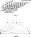
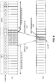
- the basic LTE downlink physical resource can thus be seen as a time-frequency grid as illustrated in Figure 1 , where each Resource Element (RE) corresponds to one OFDM subcarrier during one OFDM symbol interval.
- the uplink subframe has the same subcarrier spacing as the downlink and the same number of SC-FDMA symbols in the time domain as OFDM symbols in the downlink.
- Each subframe comprises two slots of duration 0.5 ms each, and the slot numbering within a frame ranges from 0 to 19.
- one subframe consists of 14 OFDM symbols.
- the duration of each symbol is approximately 71.4 microseconds ( ⁇ s) (including cyclic prefix).
- RBs Resource Blocks
- the uplink transmissions are dynamically scheduled, i.e., in each downlink subframe the base station transmits control information about which terminals should transmit data to the enhanced or evolved Node B (eNB) in subsequent subframes, and upon which RBs the data is transmitted.
- the uplink resource grid is comprised of data and uplink control information in the Physical Uplink Shared Channel (PUSCH), uplink control information in the Physical Uplink Control Channel (PUCCH), and various reference signals such as Demodulation Reference Signals (DMRSs) and SRSs.
- PUSCH Physical Uplink Shared Channel
- PUCCH Physical Uplink Control Channel
- DMRSs Demodulation Reference Signals
- SRSs Demodulation Reference Signals
- SRSs Demodulation Reference Signals
- SRSs Demodulation Reference Signals
- SRSs Demodulation Reference Signals
- SRSs Demodulation Reference Signals
- SRSs are used for coherent demodulation of PUSCH and PUCCH data.
- the PUSCH DMRS is transmitted once
- the subframes in which SRSs are transmitted by any UE within a cell are indicated by cell-specific broadcast signaling.
- a 4-bit cell-specific 'srsSubframeConfiguration' parameter indicates 15 possible sets of subframes in which SRS may be transmitted within each radio frame. As noted before, the SRS transmissions are always in the last SC-FDMA symbol in the configured uplink subframes, and PUSCH transmission may not be permitted on these symbols.
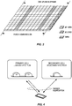
- SRS is not associated with any data or control information but is generally used to estimate the uplink channel quality for purposes of frequency-selective scheduling. In order to serve this purpose, it is necessary that SRSs from different UEs with different sounding bandwidths can overlap. As illustrated in Figure 3 , interleaved Frequency Division Multiple Access (FDMA) is used for SRS with a repetition factor of 2, which implies that in the configured SRS bandwidth, the SRS will be mapped to every other subcarrier in a comb-like fashion. This allows multiple UEs to simultaneously transmit SRS without overlap.
- FDMA Frequency Division Multiple Access
- a 2-comb (SRS on every other subcarrier) or 4-comb (SRS on every fourth subcarrier) can be configured for SRS in Rel-13 LTE.
- phase or cyclic shifts can be applied to SRS sequences on the same REs to make them mutually orthogonal, with up to eight such UE-specific shifts currently available per comb.
- up to 16 distinguishable full-bandwidth SRS sequences can currently be assigned to UEs.
- Up to six symbols of contiguous SRS transmission are supported in Rel-13 LTE, for example in the Uplink Pilot Time Slot (UpPTS) region of a special subframe.
- UpPTS Uplink Pilot Time Slot
- UEs that are capable of uplink data transmission on a limited number of component carriers can use SCBS to transmit SRS on many more Component Carriers (CCs).
- CCs Component Carriers
- the eNB can exploit downlink-uplink channel reciprocity and enhance downlink beamforming or scheduling on carriers for which the UE is unable to transmit PUSCH.
- this Work Item is mainly focused on CCs in licensed spectrum.
- the SRS transmission opportunities include:
- LTE the spectrum used by LTE is dedicated to LTE. This has the advantage that the LTE system does not need to care about the coexistence issue and the spectrum efficiency can be maximized.
- the spectrum allocated to LTE is limited which cannot meet the ever increasing demand for larger throughput from applications/services. Therefore, a new study item has been initiated in 3GPP on extending LTE to exploit unlicensed spectrum in addition to licensed spectrum. Unlicensed spectrum can, by definition, be simultaneously used by multiple different technologies. Therefore, LTE needs to consider the coexistence issue with other systems such as IEEE 802.11 (Wi-Fi). Operating LTE in the same manner in unlicensed spectrum as in licensed spectrum can seriously degrade the performance of Wi-Fi as Wi-Fi will not transmit once it detects the channel is occupied.
- Wi-Fi IEEE 802.11
- one way to utilize the unlicensed spectrum reliably is to transmit essential control signals and channels on a licensed carrier. That is, as shown in Figure 4 , a UE is connected to a Primary Cell (PCell) in the licensed band and one or more Secondary Cells (SCells) in the unlicensed band.
- PCell Primary Cell
- SCells Secondary Cells
- an SCell in unlicensed spectrum is denoted as an LAA SCell.
- SRS in 3GPP Rel-14 enhanced LAA will be based on the legacy comb design as in Rel-13 LTE.
- SRS when transmitted with PUSCH is located in symbol 13 of the uplink subframe.
- the UE transmits SRS in symbol 13.
- the existing maximum number of SRS RBs is retained for a given system bandwidth in eLAA. No shifting of SRS is used on an LAA SCell. Only aperiodic SRS transmission is supported in eLAA.
- the triggering for SRS without PUSCH is received in subframe n, the UE should send SRS without PUSCH in subframe n+k (not considering the LBT failure).
- the offset parameter k is indicated by three bits in the downlink grant, where "000" represents no triggering for SRS without PUSCH; "001" ⁇ "111" represents SRS without PUSCH is transmitted in subframe n+4 to n+11, respectively.
- MulteFire A new industry forum has been initiated on extending LTE to operate entirely on unlicensed spectrum in a standalone mode, which is referred to as "MulteFire" in marketing terms.
- the transmission needs to be carried on the unlicensed spectrum with no guaranteed channel access availability and also fulfill the regulatory requirements on the unlicensed spectrum.
- both these requirements are enforced for 5 GHz carriers according to ETSI 301 893, while only the maximum PSD requirements are enforced in the US regulation for 5 GHz.
- the occupied bandwidth requirement is expressed as the bandwidth containing 99% of the power of the signal, shall be between 80% and 100% of the declared Nominal Channel Bandwidth.
- Our current understanding of this requirement is that it is tested over a time interval longer than one subframe (1 ms).
- the frequency allocations for one UE must thus vary between subframes in such a way that the requirement is fulfilled. It is still an open issue if this requirement needs to be fulfilled for a UE which only transmits in a single subframe, such as Physical Random Access Channel (PRACH) or with a single PUSCH.
- PRACH Physical Random Access Channel
- the maximum PSD requirements exist in many different regions. For most cases the requirement is stated with a resolution bandwidth of 1 megahertz (MHz). For example, the ETSI 301 893 specification requires 10 decibel-milliwatts (dBm) / MHz for 5150-5350 MHz.
- the implication of the PSD requirement on the physical layer design is that, without proper designs, a signal with small transmission bandwidth will be limited in transmission power. This can negatively affect coverage of the operation. That is, the maximum PSD requirement is a binding condition that requires changes to uplink transmissions in unlicensed spectrums.
- interlaced transmissions as a means to give LAA uplink signals with small bandwidth higher transmission powers when needed (and, to a lesser extent, to satisfy the transmission bandwidth requirement).
- the interlacing of transmissions is done on a per Physical RB (PRB) basis.
- PRB Physical RB
- This design is also referred to as Block-Interleaved FDMA (B-IFDMA).
- B-IFDMA Block-Interleaved FDMA
- Interlaced uplink transmissions are also used in MulteFire.
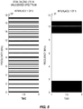
- the figure to the right shows the first 1.2 MHz of the same allocation.
- the hashed lines represent example boundaries of the PSD requirement measurement intervals (1 MHz resolution bandwidth).
- the black stripes represent the allocated RBs for the interlace.
- the SRS transmissions in MulteFire are also interlaced.
- the SRS in MulteFire is different in the frequency domain compared to eLAA, since the eLAA SRS follows the legacy LTE structure.
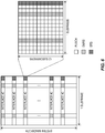
- An example of interlace-based SRS in MulteFire is shown in Figure 6 , where the SRS is located in symbol 13 in the time domain and on interlace #0 in the frequency domain.
- MulteFire SRS In MulteFire SRS, comb structure is not supported. Therefore, cyclic shifts and/or Orthogonal Cover Code (OCC) are used to multiplex different antenna ports from a UE, or to multiplex different UEs on the same interlace. Up to four symbols of SRS can be transmitted by a UE in the short PUCCH (sPUCCH) region of a partial downlink Transmit Time Interval (TTI).
- sPUCCH short PUCCH
- TTI partial downlink Transmit Time Interval
- LTE-U Long Term Evolution
- the SRS and SCBS originally designed for LTE on licensed spectrum cannot be reused because of the following problems.
- Second, the SRS multiplexing rules for UEs that are switching SRS to a particular carrier and UEs that can send PUSCH on that carrier will be different for eLAA and MulteFire due to the different SRS structures.
- UE RF issues related to SRS carrier based switching for LTE 3GPP DRAFT, TSG-RAN WG4 #79, R4-164223 (2016 ).
- Some further information is provided in Ericsson: “Scenarios for SRS carrier based switching for LTE”, 3GPP DRAFT, 3GPP TSG-RAN WG4 #79, R4-164223 (2016 ).
- WO 2016/048227 A1 describes an enhanced Reference Signal, RS, that is designed to be available for transmission in any symbol of a subframe.
- a method of operation of a User Equipment device (UE) in a wireless system comprises performing uplink Listen-Before-Talk (LBT) on one or more candidate carriers for switched carrier SRS transmission and performing a switched carrier SRS transmission on at least one candidate carrier of the one or more candidate carriers that is determined to be available as a result of performing the uplink LBT on the one or more candidate carriers.
- the one or more candidate carriers are carriers other than carriers configured for the UE and on which the UE is scheduled to transmit.
- performing the uplink LBT on the one or more candidate carriers for switched carrier SRS transmission comprises performing the uplink LBT on a candidate carrier, a result of the uplink LBT being that the candidate carrier is available, and performing the switched carrier SRS transmission on the at least one candidate carrier comprises performing the switched carrier SRS transmission on the candidate carrier in response to the result of the uplink LBT being that the candidate carrier is available.
- the method further comprises, prior to performing the uplink LBT on the candidate carrier, starting uplink transmission on a first carrier, the first carrier being different than the candidate carrier.
- the method further comprises, after performing the switched carrier SRS transmission on the candidate carrier, performing uplink LBT on the first carrier, a result of the uplink LBT on the first carrier being that the first carrier is available and resuming the uplink transmission on the first carrier upon the result of the uplink LBT on the first carrier being that the first carrier is available.
- performing the uplink LBT on the one or more candidate carriers for switched carrier SRS transmission comprises performing multi-carrier uplink LBT on a first set of carriers for which the UE is granted uplink transmission and a second set of carriers comprising the one or more candidate carriers, the first set of carriers and the second set of carriers being disjoint sets, where the at least one candidate carrier on which the UE performs switched carrier SRS transmission comprises at least one candidate carrier from the one or more candidate carriers in the second set of carriers.
- performing multi-carrier uplink LBT on the first set of carriers for which the UE is granted uplink transmission and the second set of carriers comprising the one or more candidate carriers comprises suspending uplink transmission on at least one of the carriers in the first set of carriers prior to transmitting SRS on the at least one candidate carrier.
- performing multi-carrier uplink LBT on the first set of carriers for which the UE is granted uplink transmission and the second set of carriers comprising the one or more candidate carriers comprises suspending uplink transmission on all of the carriers in the first set of carriers prior to transmitting SRS on the at least one candidate carrier.
- performing the switched carrier SRS transmission on the at least one candidate carrier comprises performing the switched carrier SRS transmission on the at least one candidate carrier in accordance with an SRS transmission multiplexing configuration for a respective group of UEs such that the switched carrier SRS transmission on the at least one candidate carrier is multiplexed with uplink transmissions of another group of UEs on the same at least one candidate carrier.
- performing the switched carrier SRS transmission on the at least one candidate carrier comprises performing the switched carrier SRS transmission on the at least one candidate carrier in accordance with an SRS transmission multiplexing configuration for a respective group of UEs such that the switched carrier SRS transmission on the at least one candidate carrier is multiplexed with SRS transmission of another group of UEs on the same at least one candidate carrier. Further, in some examples, the switched carrier SRS transmissions of the respective group of UEs are multiplexed with the SRS transmissions of another group of UEs in a particular symbol of the same subframe on the same at least one carrier.
- the switched carrier SRS transmissions of the respective group of UEs are multiplexed with the SRS transmissions of another group of UEs using different time-domain Orthogonal Cover Codes (OCCs).
- OCCs time-domain Orthogonal Cover Codes
- the switched carrier SRS transmissions of the respective group of UEs are multiplexed with the SRS transmissions of another group of UEs using different time-domain OCCs and different intra-symbol frequency-domain OCCs and cyclic shifts.
- a UE for a wireless system is adapted to perform uplink LBT on one or more candidate carriers for switched carrier SRS transmission and perform a switched carrier SRS transmission on at least one candidate carrier of the one or more candidate carriers that is determined to be available as a result of performing the uplink LBT on the one or more candidate carriers.
- the UE is further adapted to operate according to any of the other examples of the method of operation of the UE described herein.
- a UE for a wireless system comprises at least one transceiver, at least one processor, and memory comprising instructions executable by the at least one processor whereby the UE is operable to perform uplink LBT on one or more candidate carriers for switched carrier SRS transmission and perform a switched carrier SRS transmission on at least one candidate carrier of the one or more candidate carriers that is determined to be available as a result of performing the uplink LBT on the one or more candidate carriers.
- a UE for a wireless system comprises an uplink LBT module operable to perform uplink LBT on one or more candidate carriers for switched carrier SRS transmission and a switched carrier SRS transmission module operable to perform a switched carrier SRS transmission on at least one candidate carrier of the one or more candidate carriers that is determined to be available as a result of performing the uplink LBT on the one or more candidate carriers.
- a method of operation of a UE in a wireless system comprises receiving an indication of an SRS switching opportunity from a network node and performing one or more switched carrier SRS transmissions in accordance with the indication of the SRS switching opportunity.
- the indication of the SRS switching opportunity is any one or any combination of: an indication of a specific subframe in which to attempt SRS Carrier Based Switching (SCBS) on one or more switched carriers, a number of contiguous SRS symbols that are to be transmitted with switching is performed in a downlink partial ending subframe, a set of carriers on which to attempt SRS switching, an indication of one or more uplink interlaces on which the switched SRS transmissions are to be transmitted, a contention-window or Clear Channel Assessment (CCA) duration to be used for uplink LBT for switched SRS transmissions, an indication of whether uplink LBT can be skipped prior to SRS transmission on a switched carrier, and an indication of whether SRS switching is to be triggered to deferred to a next periodic opportunity.
- SCBS SRS Carrier
- a UE for a wireless system is adapted to receive an indication of an SRS switching opportunity from a network node and perform one or more switched carrier SRS transmissions in accordance with the indication of the SRS switching opportunity.
- a UE for a wireless system comprises at least one transceiver, at least one processor, and memory comprising instructions executable by the at least one processor whereby the UE is operable to receive an indication of an SRS switching opportunity from a network node and perform one or more switched carrier SRS transmissions in accordance with the indication of the SRS switching opportunity.
- a UE for a wireless system comprises a receiving module operable to receive an indication of an SRS switching opportunity from a network node and a performing module operable to perform one or more switched carrier SRS transmissions in accordance with the indication of the SRS switching opportunity.
- Radio Node As used herein, a "radio node” is either a radio access node or a wireless device.
- Radio Access Node is any node in a radio access network of a cellular communications network that operates to wirelessly transmit and/or receive signals.
- a radio access node include, but are not limited to, a base station (e.g., an enhanced or evolved Node B (eNB) in a Third Generation Partnership Project (3GPP) Long Term Evolution (LTE) network), a high-power or macro base station, a low-power base station (e.g., a micro base station, a pico base station, a home eNB, or the like), and a relay node.
- a base station e.g., an enhanced or evolved Node B (eNB) in a Third Generation Partnership Project (3GPP) Long Term Evolution (LTE) network
- 3GPP Third Generation Partnership Project
- LTE Long Term Evolution
- a “core network node” is any type of node in a Core Network (CN).
- Some examples of a core network node include, e.g., a Mobility Management Entity (MME), a Packet Data Network (PDN) Gateway (P-GW), a Service Capability Exposure Function (SCEF), or the like.
- MME Mobility Management Entity
- PDN Packet Data Network
- SCEF Service Capability Exposure Function
- a "wireless device” or “UE” is any type of device that has access to (i.e., is served by) a wireless network (e.g., a cellular communications network) by wirelessly transmitting and/or receiving signals to a radio access node(s).
- a wireless device include, but are not limited to, a UE in a 3GPP network and a Machine Type Communication (MTC) device.
- MTC Machine Type Communication
- Network Node As used herein, a "network node” is any node that is either part of the radio access network or the CN of a cellular communications network/system.
- 3GPP LTE terminology or terminology similar to 3GPP LTE terminology is oftentimes used.
- the concepts disclosed herein are not limited to LTE or a 3GPP system.
- LAA License Assisted Access
- NR 5G New Radio
- the present disclosure describes new designs for Sounding Reference Signal (SRS) carrier based switching in unlicensed spectrum. Two separate cases are considered: legacy SRS as in enhanced LAA (eLAA), and interlaced SRS as applicable to MulteFire.
- SRS Sounding Reference Signal
- SRS Carrier Based Switching is enabled on unlicensed carriers.
- SRS multiplexing rules for UEs that are switching SRS to a particular carrier and UEs that can send Physical Uplink Shared Channel (PUSCH) on that carrier are defined for both eLAA with legacy SRS and MulteFire with interlaced SRS.
- Efficient rules are defined for the indication of SRS switching opportunities by the LAA / MulteFire eNB.
- FIG. 7 illustrates one example of a wireless system 10 in which embodiments of the present disclosure may be implemented.
- the wireless system 10 may be a cellular communications network.
- the wireless system 10 includes a base station 12 that operates to serve a number of cells (Cell 1 to Cell N) on a number of different carriers (Carrier 1 to Carrier N, respectively). Some or all of the carriers are in an unlicensed frequency spectrum or some other spectrum that requires Listen-Before-Talk (LBT), or carrier sensing, prior to transmission.
- LBT Listen-Before-Talk
- the wireless system 10 may be an LAA system in which at least one of the carriers is in a licensed spectrum and at least some of the other carriers are in an unlicensed spectrum.
- the wireless system 10 is a MulteFire or similar system providing standalone operation in an unlicensed frequency spectrum (i.e., the carriers are all in the unlicensed spectrum or standalone operation is provided on at least some of the carriers in an unlicensed spectrum).
- the base station 12 may be, for example, an eNB in a LTE or LTE-based cellular communications network.
- the base station 12 provides wireless access to a number of UEs 14, which may also be referred to herein as wireless devices. Note that while only one base station 12 is illustrated in this example, the cells may alternatively be provided by multiple base stations or radio access nodes.
- the first embodiment focuses on the choice of the carrier to which SRS switching is performed.
- the choice of which carrier to switch to is based on the outcome of uplink LBT performed by the UE 14 on a set of one or more candidate switching carriers (i.e., one or more of the carriers that are candidates for switching SRS transmission), excluding the carriers on which it is currently configured and scheduled to transmit PUSCH / Physical Uplink Control Channel (PUCCH).
- PUCCH Physical Uplink Control Channel
- FIG. 8 A first example is shown in Figure 8 where the UE 14 is configured to perform PUSCH transmissions on Component Carrier 1 (CC1).
- the UE 14 then performs an uplink LBT operation on CC2, which finds the channel to be unoccupied. This is then followed by a switched SRS transmission on CC2, after which the UE 14 switches back to CC1, performs an uplink LBT on CC1, and resumes any PUSCH/PUCCH transmissions that it has been scheduled for.
- the uplink LBT operation on CC2 may be of a duration that is specified by the base station 12 (e.g., eNB) via broadcast System Information (SI) or configured via higher layer signaling.
- SI System Information
- the subframe in which the UE 14 attempts uplink LBT on CC2 may be determined based on reading Common Physical Downlink Control Channel (C-PDCCH) information from either the serving cell CC1 or CC2, where the C-PDCCH carries information regarding the upcoming downlink-uplink subframe allocation on one or more carriers.
- C-PDCCH Common Physical Downlink Control Channel
- the base station 12 optionally configures the UE 14 to perform shared channel uplink transmission (e.g., PUSCH transmission) on a first carrier (step 100).
- the UE 14 begins uplink transmission on the first carrier according to the configuration of step 100 (step 102).
- the UE 14 performs uplink LBT on a candidate carrier for switched carrier SRS transmission (step 104).
- the candidate carrier is a carrier other than the first carrier configured for the UE 14 and on which the UE 14 is scheduled to transmit.
- the uplink LBT procedure determines that the candidate carrier is available and, as such, the UE 14 performs a switched carrier SRS transmission on the candidate carrier (step 106). In other words, the UE 14 suspends uplink transmission on the first carrier, switches to the candidate carrier, and transmits SRS on the candidate carrier.
- the base station 12 receives and processes the switched carrier SRS transmission (step 108).
- the UE 14 performs uplink LBT on the first carrier (step 110). Upon determining that the first carrier is available, the UE 14 resumes uplink transmission on the first carrier (step 112).
- the uplink LBT on candidate switching carriers is performed together with uplink LBT on carriers for which the UE 14 has received uplink PUSCH/PUCCH grants.
- the LBT mechanism can be based on either 'Type A' or 'Type B.' In Type A, independent random backoff is performed on each candidate CC, while in Type B, a full random backoff with multiple Clear Channel Assessment (CCA) slots is performed on a specific carrier, while a quick CCA check (e.g., of duration 25 microseconds ( ⁇ s)) is performed on all other carriers before the start of transmission on the random backoff carrier. In both types, uplink transmission is performed only on those carriers which are deemed to be unoccupied.
- CCA Clear Channel Assessment
- S1 denote the set of candidate carriers for SRS switching
- S2 denote the set of carriers for which the UE 14 has received uplink transmission grants
- S1 and S2 being mutually exclusive (i.e., S1 and S2 are disjoint sets).
- the set S1 may be indicated by the serving cell.
- the UE 14 performs LBT on both sets S1 and S2 simultaneously. If the LBT mechanism is based on Type B, then the UE 14 performs a full random backoff on one of the carriers in set S2, and utilizes a quick CCA check on all other carriers in S1 and S2.
- the UE 14 utilizes the same Contention Window (CW) for carriers in S1 as the CW used for carriers in S2, where the CW may have been indicated in the uplink grant(s) for S2 by the eNB.
- CW Contention Window
- the base station 12 optionally transmits a grant to the UE 14 for uplink transmission on a first set of carriers (S1) (step 200).
- the grant is, in some embodiments, a grant for a PUSCH transmission and/or a PUCCH transmission.
- the first set of carriers (S1) includes one or more carriers.
- the UE 14 performs multi-carrier uplink LBT on the first set of carriers (S1) and a second set of candidate carriers (S2) for switched carrier SRS transmission (step 202).
- the second set of candidate carriers (S2) includes one or more carriers.
- the first and second sets of carriers (S1 and S2) are mutually exclusive.
- Multi-carrier uplink LBT is a procedure by which the UE 14 simultaneously performs uplink LBT on multiple carriers, where in step 202 these multiple carriers include the carriers in the first and second sets of carriers (S1 and S2).
- the UE 14 selects one or more of the candidate carriers in the second set (S2) that are available, as determined by the multi-carrier uplink LBT procedure, for switched carrier SRS transmission (step 204).
- the UE 14 performs switched carrier SRS transmission on the (selected) candidate carrier(s) (step 206). Alternatively, the UE 14 may perform switched carrier SRS transmission on all available carriers in the second set (S2). In some embodiments, the UE 14 suspends uplink transmission on at least one and possibly all of the carriers in the first set of carriers (S1) in order to transmit SRS on the (selected) candidate carriers from the second set (S2).
- the base station 12 receives and processes the uplink switched carrier SRS transmission (step 208).
- multiplexing of switched SRS transmissions is provided.
- switched SRS transmissions from UEs that are switching from another CC are multiplexed with ongoing transmissions from UEs configured to use the same CC for their uplink transmissions.
- D1 and D2 an uplink CC
- UEs in group D1 switch from CCs other than CC1 to transmit SRS on CC1, i.e., these UEs perform SCBS.
- UEs in group D2 are configured for uplink PUSCH, PUCCH, and SRS transmissions on CC1, i.e., they are not performing SCBS.
- the first aspect relates to switched SRS multiplexing for eLAA transmissions.
- the switched SRS transmissions from group D1 UEs are multiplexed with SRS transmissions from group D2 UEs in symbol 13 of the same subframe (uplink or downlink partial ending).
- the group D2 UEs are configured to transmit SRS without PUSCH, such that a gap is available prior to symbol 13 for uplink LBT by both group D1 and D2 UEs.
- the switched group D1 SRSs and regular group D2 SRSs are assigned different combs and/or cyclic shifts in order to multiplex them in the same symbol location.
- the second aspect relates to switched SRS multiplexing for MulteFire CCs.
- SRS multiplexing is performed with multiple SRS symbols in the downlink partial ending subframe (Uplink Pilot Time Slot (UpPTS)) region of the switched carrier
- time-domain Orthogonal Cover Codes may be used to pack group D1 and D2 UEs on the same uplink interlace.
- this OCC can be defined as a set of four configurations: w ⁇ ⁇ [1,1,1,1], [1,1, -1, -1], [1, -1,1, -1], [1, -1, -1,1] ⁇ .
- intra-symbol frequency-domain OCC and cyclic shifts may also be used to multiplex group D1 and D2 UEs on the same uplink interlace.
- intra-symbol frequency-domain OCC and cyclic shifts may also be used to multiplex group D1 and D2 UEs on the same uplink interlace.
- group D1 and group D2 UEs may be assigned different uplink interlaces. This way, D2 UEs may transmit any uplink channel/reference signal such as PUSCH, PUCCH, or SRS in the same subframe as the switched SRS transmissions from group D1 UEs without mutual interference.
- Figure 11 illustrates one example of multiplexing of switched SRS transmissions from different groups of UEs 14 according to some embodiments of the present disclosure.
- Optional steps are illustrated by dashed lines. Also, unless otherwise explicitly stated or otherwise required, the steps may be performed in any order.
- the base station 12 optionally configures a first group of UEs 14 with an SRS transmission multiplexing configuration for the first group of UEs 14 (group 1 or D1) (step 300) and optionally configures a second group of UEs 14 with an SRS transmission multiplexing configuration for the second group of UEs 14 (group 2 or D2) (step 302), as described above.
- the UE(s) 14 in the first group perform uplink LBT on one or more candidate carrier(s) for switched carrier SRS transmission (step 304).
- the UE(s) 14 may perform single carrier uplink LBT (i.e., uplink LBT on a single carrier) or multi-carrier uplink LBT, e.g., as described above.
- the UE(s) 14 selects one (or potentially multiple) candidate carrier(s) that is(are) available for switched carrier SRS transmission (step 306).
- the UE(s) 14 perform switched carrier SRS transmission on the (selected) candidate carrier(s) determined to be available using the SRS transmission multiplexing configuration for group 1 (step 308).
- the UE(s) 14 in the second group multiplex their SRS transmission on the same carrier(s) using the SRS transmission configuration for group 2 (step 310).
- the UEs 14 in the first and second groups are able to multiplex their SRS transmissions on the same carrier(s).
- the base station 12 receives and processes the SRS transmissions from the UEs 14 in the first and second groups of UEs (step 312).
- mechanisms for indication of SRS switching opportunity by the base station 12 are provided.
- PHICH Physical Hybrid Automatic Repeat Request Indicator Channel
- Figure 12 illustrates one example of this embodiment.
- the base station 12 transmits an indication of SRS switching opportunity to the UE 14 (step 400).
- the indication may be any one or any combination of the examples given above.
- the UE 14 performs switched carrier SRS transmission(s) according to the received indication (step 402).
- the present disclosure describes how to implement SRS carrier based switching on carriers in unlicensed spectrum. Solutions for both eLAA and MulteFire are presented.
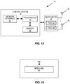
- FIG. 13 is a schematic block diagram of the base station 12 according to some embodiments of the present disclosure.
- the base station 12 includes a control system 16 that includes one or more processors 18 (e.g., Central Processing Units (CPUs), Application Specific Integrated Circuits (ASICs), Field Programmable Gate Arrays (FPGAs), and/or the like), memory 20, and a network interface 22.
- the base station 12 includes one or more radio units 24 that each includes one or more transmitters 26 and one or more receivers 28 coupled to one or more antennas 30.
- the radio unit(s) 24 is external to the control system 16 and connected to the control system 16 via, e.g., a wired connection (e.g., an optical cable).
- the radio unit(s) 24 and potentially the antenna(s) 30 are integrated together with the control system 16.
- the one or more processors 18 operate to provide one or more functions of a base station 12 as described herein.
- the function(s) are implemented in software that is stored, e.g., in the memory 20 and executed by the one or more processors 18.
- Figure 14 is a schematic block diagram that illustrates a virtualized embodiment of the base station 12 according to some embodiments of the present disclosure. This discussion is equally applicable to other types of network nodes. Further, other types of network nodes may have similar virtualized architectures.
- a "virtualized" base station 12 is an implementation of the base station 12 in which at least a portion of the functionality of the base station 12 is implemented as a virtual component(s) (e.g., via a virtual machine(s) executing on a physical processing node(s) in a network(s)).
- the base station 12 includes the control system 16 (optional) that includes the one or more processors 18 (e.g., CPUs, ASICs, FPGAs, and/or the like), the memory 20, and the network interface 22 and the one or more radio units 24 that each includes the one or more transmitters 26 and the one or more receivers 28 coupled to the one or more antennas 30, as described above.
- the control system 16 includes the one or more processors 18 (e.g., CPUs, ASICs, FPGAs, and/or the like), the memory 20, and the network interface 22 and the one or more radio units 24 that each includes the one or more transmitters 26 and the one or more receivers 28 coupled to the one or more antennas 30, as described
- the control system 16 is connected to the radio unit(s) 24 via, for example, an optical cable or the like.
- the control system 16 is connected to one or more processing nodes 32 coupled to or included as part of a network(s) 34 via the network interface 22.
- Each processing node 32 includes one or more processors 36 (e.g., CPUs, ASICs, FPGAs, and/or the like), memory 38, and a network interface 40.
- functions 42 of the base station 12 described herein are implemented at the one or more processing nodes 32 or distributed across the control system 16 and the one or more processing nodes 32 in any desired manner.
- some or all of the functions 42 of the base station 12 described herein are implemented as virtual components executed by one or more virtual machines implemented in a virtual environment(s) hosted by the processing node(s) 32.
- additional signaling or communication between the processing node(s) 32 and the control system 16 is used in order to carry out at least some of the desired functions 42.
- the control system 16 may not be included, in which case the radio unit(s) 24 communicate directly with the processing node(s) 32 via an appropriate network interface(s).
- a computer program including instructions which, when executed by at least one processor, causes the at least one processor to carry out the functionality of a base station 12 or a node (e.g., a processing node 32) implementing one or more of the functions 42 of the base station 12 in a virtual environment according to any of the embodiments described herein is provided.
- a carrier comprising the aforementioned computer program product is provided.
- the carrier is one of an electronic signal, an optical signal, a radio signal, or a computer readable storage medium (e.g., a non-transitory computer readable medium such as memory).
- FIG 15 is a schematic block diagram of the base station 12 according to some other embodiments of the present disclosure.
- the base station 12 includes one or more modules 44, each of which is implemented in software.
- the module(s) 44 provide the functionality of the base station 12 described herein. This discussion is equally applicable to the processing node 32 of Figure 14 where the modules 44 may be implemented at one of the processing nodes 32 or distributed across multiple processing nodes 32 and/or distributed across the processing node(s) 32 and the control system 16.
- FIG 16 is a schematic block diagram of a UE 14 according to some embodiments of the present disclosure.
- the UE 14 includes one or more processors 46 (e.g., CPUs, ASICs, FPGAs, and/or the like), memory 48, and one or more transceivers 50 each including one or more transmitters 52 and one or more receivers 54 coupled to one or more antennas 56.
- processors 46 e.g., CPUs, ASICs, FPGAs, and/or the like
- memory 48 e.g., RAM, RAM, programmable gate array, and/or the like
- transceivers 50 each including one or more transmitters 52 and one or more receivers 54 coupled to one or more antennas 56.
- the functionality of the UE 14 described above may be fully or partially implemented in software that is, e.g., stored in the memory 48 and executed by the processor(s) 46.
- a computer program including instructions which, when executed by at least one processor, causes the at least one processor to carry out the functionality of the UE 14 according to any of the embodiments described herein is provided.
- a carrier comprising the aforementioned computer program product is provided.
- the carrier is one of an electronic signal, an optical signal, a radio signal, or a computer readable storage medium (e.g., a non-transitory computer readable medium such as memory).
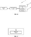
- FIG 17 is a schematic block diagram of the UE 14 according to some other embodiments of the present disclosure.
- the UE 14 includes one or more modules 58, each of which is implemented in software.
- the module(s) 58 provide the functionality of the UE 14 described herein.
Landscapes
- Engineering & Computer Science (AREA)
- Signal Processing (AREA)
- Computer Networks & Wireless Communication (AREA)
- Power Engineering (AREA)
- Mobile Radio Communication Systems (AREA)
Claims (11)
- Betriebsverfahren eines Benutzergeräts (User Equipment, UE) (14) in einem drahtlosen System (10), das Folgendes umfasst:Durchführen (104, 202, 304) von Uplink-Listen-Before-Talk, LBT, auf einem oder mehreren Kandidatenträgern für die Übertragung von Schallempfängersignalen (Sounding Reference Signal, SRS) von geschalteten Trägern; undDurchführen (106, 206, 308) einer SRS-Übertragung mit geschaltetem Träger auf mindestens einem Kandidatenträger des einen oder der mehreren Kandidatenträger, der als Ergebnis der Durchführung (104, 202, 304) der Uplink-LBT auf dem einen oder den mehreren Kandidatenträgern als verfügbar bestimmt wird, wobei das Durchführen der SRS-Übertragung mit geschaltetem Träger auf dem mindestens einen Kandidatenträger das Durchführen der SRS-Übertragung mit geschaltetem Träger auf dem mindestens einen Kandidatenträger gemäß einer SRS-Übertragungsmultiplexkonfiguration für eine jeweilige Gruppe von UEs (14) umfasst, so dass die SRS-Übertragung mit geschaltetem Träger auf dem mindestens einen Kandidatenträger mit Uplink-Übertragungen oder der SRS-Übertragung einer anderen Gruppe von UEs (14) auf demselben mindestens einem Kandidatenträger gemultiplext wird.
- Verfahren nach Anspruch 1, wobei der eine oder die mehreren Kandidatenträger andere Träger als Träger sind, die für das UE (14) konfiguriert sind und auf denen das UE (14) für eine Sendung eingeplant ist.
- Verfahren nach Anspruch 1 oder 2, wobei:das Durchführen (104, 202, 304) des Uplink-LBT auf dem einen oder den mehreren Kandidatenträgern für die SRS-Übertragung mit geschaltetem Träger das Durchführen (104) des Uplink-LBT auf einem Kandidatenträger umfasst, wobei ein Ergebnis der Uplink-LBT darin besteht, dass der Kandidatenträger verfügbar ist; unddas Durchführen (106, 206, 308) der SRS-Übertragung mit geschaltetem Träger auf dem mindestens einen Kandidatenträger das Durchführen (106) der SRS-Übertragung mit geschaltetem Träger auf dem Kandidatenträger als Reaktion auf das Ergebnis des Uplink-LBT, dass der Kandidatenträger verfügbar ist, umfasst.
- Verfahren nach Anspruch 3, das ferner Folgendes umfasst:vor dem Durchführen (104) des Uplink-LBT auf dem Kandidatenträger, Starten (102) der Uplink-Übertragung auf einem ersten Träger, wobei der erste Träger von dem Kandidatenträger verschieden ist; undnach dem Durchführen (106) der SRS-Übertragung mit geschaltetem Träger auf dem Kandidatenträger:Durchführen eines (110) Uplink-LBT auf dem ersten Träger, wobei das Ergebnis des Uplink-LBT auf dem ersten Träger darin besteht, dass der erste Träger verfügbar ist; undWiederaufnahme (112) der Uplink-Übertragung auf dem ersten Träger, wenn das Ergebnis der Uplink-LBT auf dem ersten Träger darin besteht, dass der erste Träger verfügbar ist.
- Verfahren nach Anspruch 1 oder 2, wobei:das Durchführen (104, 202, 304) des Uplink-LBT auf dem einen oder den mehreren Kandidatenträgern für die SRS-Übertragung mit geschaltetem Träger Folgendes umfasst: Durchführen (202) des Uplink-LBT mit mehreren Trägern auf einem ersten Satz von Trägern, für die dem UE (14) eine Uplink-Übertragung gewährt wird, und einen zweiten Satz von Trägern, der den einen oder die mehreren Kandidatenträger umfasst, wobei der erste Satz von Trägern und der zweite Satz von Trägern disjunkte Sätze sind; undwobei der mindestens eine Kandidatenträger, auf dem das UE (14) eine SRS-Übertragung mit geschaltetem Träger durchführt, mindestens einen Kandidatenträger von dem einen oder den mehreren Kandidatenträgern in dem zweiten Satz von Trägern umfasst.
- Verfahren nach Anspruch 5, wobei das Durchführen (202) eines Mehrträger-Uplink-LBT an dem ersten Satz von Trägern, für den dem UE (14) eine Uplink-Übertragung gewährt wird, und dem zweiten Satz von Trägern, der den einen oder die mehreren Kandidatenträger umfasst, das Unterbrechen der Uplink-Übertragung auf mindestens einem der Träger im ersten Satz von Trägern vor dem Übertragen von SRS auf dem mindestens einen Kandidatenträger umfasst.
- Verfahren nach Anspruch 5, wobei das Durchführen (202) eines Mehrträger-Uplink-LBT an dem ersten Satz von Trägern, für den dem UE (14) eine Uplink-Übertragung gewährt wird, und dem zweiten Satz von Trägern, der den einen oder die mehreren Kandidatenträger umfasst, das Unterbrechen der Uplink-Übertragung auf allen Trägern im ersten Satz von Trägern vor dem Übertragen von SRS auf dem mindestens einen Kandidatenträger umfasst.
- Verfahren nach einem der Ansprüche 1 bis 7, wobei die SRS-Übertragungen mit geschaltetem Träger der jeweiligen Gruppe von UEs (14) mit den SRS-Übertragungen einer anderen Gruppe von UEs (14) in einem bestimmten Symbol desselben Teilrahmens auf dem gleichen mindestens einen Träger gemultiplext werden.
- Verfahren nach einem der Ansprüche 1 bis 7, wobei die SRS-Übertragungen mit geschaltetem Träger der jeweiligen Gruppe von UEs (14) mit den SRS-Übertragungen einer anderen Gruppe von UEs (14) unter Verwendung verschiedener orthogonaler Zeitbereichs-Abdeckungscodes (Orthogonal Cover Codes, OCCs) gemultiplext werden.
- Verfahren nach einem der Ansprüche 1 bis 7, wobei die SRS-Übertragungen mit geschaltetem Träger der jeweiligen Gruppe von UEs (14) mit den SRS-Übertragungen einer anderen Gruppe von UEs unter Verwendung verschiedener orthogonaler Zeitbereichs-Abdeckungscodes, OCCs, und verschiedener Intra-Symbol-Frequenzbereichs-OCCs und zyklischer Verschiebungen gemultiplext werden.
- Benutzergerät UE (14) für ein drahtloses System (10), das Folgendes umfasst:mindestens einen Sendeempfänger (50);mindestens einen Prozessor (46); undeinen Speicher (48) mit Anweisungen, die von dem mindestens einen Prozessor (46) ausführbar sind, wobei das UE (14) für Folgendes ausgelegt ist:Durchführen von Uplink-Listen-Before-Talk, LBT, auf einem oder mehreren Kandidatenträgern für die Übertragung von Schallempfängersignalen, SRS, von geschalteten Trägern; undDurchführen einer SRS-Übertragung mit geschaltetem Träger auf mindestens einem Kandidatenträger des einen oder der mehreren Kandidatenträger, die als Ergebnis der Durchführung des Uplink-LBT auf dem einen oder den mehreren Kandidatenträgern als verfügbar bestimmt wird; wobei die SRS-Übertragung mit geschaltetem Träger auf dem mindestens einen Kandidatenträger gemäß einer SRS-Übertragungsmultiplexkonfiguration für eine jeweilige Gruppe von UEs (14) durchgeführt wird, so dass die SRS-Übertragung mit geschaltetem Träger auf dem mindestens einen Kandidatenträger mit Uplink-Übertragungen oder der SRS-Übertragung einer anderen Gruppe von UEs (14) auf demselben mindestens einem Kandidatenträger gemultiplext wird.
Priority Applications (2)
| Application Number | Priority Date | Filing Date | Title |
|---|---|---|---|
| PL17758621T PL3488552T3 (pl) | 2016-07-20 | 2017-07-20 | Przełączanie SRS oparte na nośnej na nielicencjonowanych pasmach |
| EP20190769.8A EP3758270B1 (de) | 2016-07-20 | 2017-07-20 | Auf srs-träger basierte umschaltung auf unlizenzierten bändern |
Applications Claiming Priority (2)
| Application Number | Priority Date | Filing Date | Title |
|---|---|---|---|
| US201662364454P | 2016-07-20 | 2016-07-20 | |
| PCT/IB2017/054400 WO2018015918A1 (en) | 2016-07-20 | 2017-07-20 | Srs carrier based switching on unlicensed bands |
Related Child Applications (1)
| Application Number | Title | Priority Date | Filing Date |
|---|---|---|---|
| EP20190769.8A Division EP3758270B1 (de) | 2016-07-20 | 2017-07-20 | Auf srs-träger basierte umschaltung auf unlizenzierten bändern |
Publications (2)
| Publication Number | Publication Date |
|---|---|
| EP3488552A1 EP3488552A1 (de) | 2019-05-29 |
| EP3488552B1 true EP3488552B1 (de) | 2020-09-02 |
Family
ID=59738380
Family Applications (2)
| Application Number | Title | Priority Date | Filing Date |
|---|---|---|---|
| EP17758621.1A Active EP3488552B1 (de) | 2016-07-20 | 2017-07-20 | Auf srs-träger basierte umschaltung auf unlizenzierten bändern |
| EP20190769.8A Active EP3758270B1 (de) | 2016-07-20 | 2017-07-20 | Auf srs-träger basierte umschaltung auf unlizenzierten bändern |
Family Applications After (1)
| Application Number | Title | Priority Date | Filing Date |
|---|---|---|---|
| EP20190769.8A Active EP3758270B1 (de) | 2016-07-20 | 2017-07-20 | Auf srs-träger basierte umschaltung auf unlizenzierten bändern |
Country Status (5)
| Country | Link |
|---|---|
| US (2) | US11259321B2 (de) |
| EP (2) | EP3488552B1 (de) |
| CN (1) | CN109478980B (de) |
| PL (1) | PL3488552T3 (de) |
| WO (1) | WO2018015918A1 (de) |
Families Citing this family (21)
| Publication number | Priority date | Publication date | Assignee | Title |
|---|---|---|---|---|
| CN114884640B (zh) | 2016-03-31 | 2024-07-30 | 北京三星通信技术研究有限公司 | 通信系统中的终端、基站及其方法 |
| EP3488552B1 (de) | 2016-07-20 | 2020-09-02 | Telefonaktiebolaget LM Ericsson (publ) | Auf srs-träger basierte umschaltung auf unlizenzierten bändern |
| JP7035029B2 (ja) * | 2017-04-27 | 2022-03-14 | 株式会社Nttドコモ | 端末、無線通信方法、基地局及びシステム |
| US10708021B2 (en) * | 2017-08-11 | 2020-07-07 | Lg Electronics Inc. | Method for transmitting SRS in a wireless communication system and apparatus therefor |
| US12022448B2 (en) * | 2017-08-11 | 2024-06-25 | Qualcomm Incorporated | Carrier switching for multiple carriers using the same components of a component path |
| CN109802799B (zh) * | 2017-11-17 | 2024-12-03 | 华为技术有限公司 | 用于多载波通信的载波切换方法、装置及存储介质 |
| US10863543B2 (en) * | 2017-12-01 | 2020-12-08 | Qualcomm Incorporated | Subband based uplink access for NR-SS |
| CN110198565A (zh) * | 2018-02-26 | 2019-09-03 | 普天信息技术有限公司 | 一种小带宽系统中上行资源的分配方法及装置 |
| US11290304B2 (en) * | 2018-04-13 | 2022-03-29 | Qualcomm Incorporated | SRS carrier switching with sTTI/sPT |
| CN112369088B (zh) * | 2018-05-29 | 2024-04-05 | 上海诺基亚贝尔股份有限公司 | 未许可频谱中的探测参考信号传输 |
| US11533777B2 (en) * | 2018-06-29 | 2022-12-20 | At&T Intellectual Property I, L.P. | Cell site architecture that supports 5G and legacy protocols |
| US10728826B2 (en) | 2018-07-02 | 2020-07-28 | At&T Intellectual Property I, L.P. | Cell site routing based on latency |
| CN115244976B (zh) * | 2020-03-09 | 2026-03-17 | 联想(新加坡)私人有限公司 | 执行先听后说之后的波束切换 |
| US20230328775A1 (en) * | 2020-08-14 | 2023-10-12 | Telefonaktiebolaget Lm Ericsson (Publ) | Systems and methods for changing lbt for unlicensed networks |
| JP7600516B2 (ja) * | 2020-11-11 | 2024-12-17 | ホアウェイ・テクノロジーズ・カンパニー・リミテッド | 信号送信方法、信号受信方法、及び装置 |
| CN116803047A (zh) * | 2021-02-09 | 2023-09-22 | 联想(新加坡)私人有限公司 | 使用多个dft接收csi-rs和pdsch |
| US20240080838A1 (en) * | 2021-03-12 | 2024-03-07 | Qualcomm Incorporated | Configuration for uplink transmit switching and sounding reference signal carrier switching |
| CN115333697B (zh) * | 2021-05-11 | 2024-07-05 | 大唐移动通信设备有限公司 | 上行信道的传输方法及相关装置 |
| CN118104293A (zh) * | 2021-10-20 | 2024-05-28 | 高通股份有限公司 | 针对上行链路传输切换的切换配置 |
| US20260025802A1 (en) * | 2022-07-29 | 2026-01-22 | Beijing Xiaomi Mobile Software Co., Ltd. | Uplink transmission switching method and device, and uplink transmission switching indication method and device |
| WO2025171507A1 (en) * | 2024-02-13 | 2025-08-21 | Qualcomm Incorporated | Uplink transmission switch with reference signal carrier switch |
Family Cites Families (15)
| Publication number | Priority date | Publication date | Assignee | Title |
|---|---|---|---|---|
| EP2327193B1 (de) * | 2008-08-14 | 2017-05-31 | Samsung Electronics Co., Ltd. | Verfahren und vorrichtung zur unterstüzung mehrerer referenzsignale in ofdma-kommunikationssystemen |
| WO2011041623A1 (en) * | 2009-10-01 | 2011-04-07 | Interdigital Patent Holdings, Inc. | Uplink control data transmission |
| WO2013068788A1 (en) * | 2011-11-10 | 2013-05-16 | Nokia Corporation | Methods and apparatuses for facilitating use of carrier aggregation for device-to-device communications |
| US20160050667A1 (en) * | 2014-08-18 | 2016-02-18 | Samsung Electronics Co., Ltd. | Communication on licensed and unlicensed bands |
| CN105357162B (zh) * | 2014-08-22 | 2020-12-11 | 中兴通讯股份有限公司 | 一种信号处理方法、基站和终端 |
| RU2653495C1 (ru) * | 2014-09-25 | 2018-05-10 | Телефонактиеболагет Лм Эрикссон (Пабл) | Способ и устройство для улучшенного опорного сигнала восходящей линии связи в системах listen-before-talk |
| US10038528B2 (en) * | 2014-12-19 | 2018-07-31 | Qualcomm Incorporated | Common reference signal design based on semi-uniform pilot spacing and orthogonal cover code |
| US9913290B2 (en) * | 2015-01-26 | 2018-03-06 | Asustek Computer Inc. | Method and apparatus for handling uplink transmission in a wireless communication system |
| US10200904B2 (en) * | 2015-06-24 | 2019-02-05 | Qualcomm Incorporated | Techniques for transmitting on multiple carriers of a shared radio frequency spectrum band |
| CN114698121A (zh) * | 2015-08-11 | 2022-07-01 | 三菱电机株式会社 | 通信系统 |
| ES3013564T3 (en) * | 2015-12-07 | 2025-04-14 | Ericsson Telefon Ab L M | Uplink control channel configuration for unlicensed carriers |
| CN106992804A (zh) * | 2016-01-20 | 2017-07-28 | 中兴通讯股份有限公司 | 一种探测参考信号的发送方法和装置 |
| US10333670B2 (en) * | 2016-05-06 | 2019-06-25 | Qualcomm Incorporated | Sounding reference signals with collisions in asymmetric carrier aggregation |
| CN109314684B (zh) * | 2016-05-27 | 2021-12-07 | 株式会社Ntt都科摩 | 用户终端和无线通信方法 |
| EP3488552B1 (de) * | 2016-07-20 | 2020-09-02 | Telefonaktiebolaget LM Ericsson (publ) | Auf srs-träger basierte umschaltung auf unlizenzierten bändern |
-
2017
- 2017-07-20 EP EP17758621.1A patent/EP3488552B1/de active Active
- 2017-07-20 US US16/319,002 patent/US11259321B2/en active Active
- 2017-07-20 CN CN201780044643.8A patent/CN109478980B/zh active Active
- 2017-07-20 EP EP20190769.8A patent/EP3758270B1/de active Active
- 2017-07-20 PL PL17758621T patent/PL3488552T3/pl unknown
- 2017-07-20 WO PCT/IB2017/054400 patent/WO2018015918A1/en not_active Ceased
-
2022
- 2022-01-25 US US17/584,204 patent/US11805549B2/en active Active
Non-Patent Citations (1)
| Title |
|---|
| None * |
Also Published As
| Publication number | Publication date |
|---|---|
| PL3488552T3 (pl) | 2021-01-25 |
| US11259321B2 (en) | 2022-02-22 |
| US20220150963A1 (en) | 2022-05-12 |
| WO2018015918A1 (en) | 2018-01-25 |
| US20190246427A1 (en) | 2019-08-08 |
| EP3758270B1 (de) | 2022-09-07 |
| CN109478980B (zh) | 2021-11-19 |
| CN109478980A (zh) | 2019-03-15 |
| EP3488552A1 (de) | 2019-05-29 |
| US11805549B2 (en) | 2023-10-31 |
| EP3758270A1 (de) | 2020-12-30 |
Similar Documents
| Publication | Publication Date | Title |
|---|---|---|
| US11805549B2 (en) | SRS carrier based switching on unlicensed bands | |
| US11924771B2 (en) | Uplink power control on unlicensed carriers | |
| US10827528B2 (en) | Method and apparatuses for providing parameter coordination for base stations and wireless devices | |
| EP3198773B1 (de) | Verfahren und vorrichtung für erweitertes uplink-referenzsignalen in listen-before-talk-systemen | |
| US12477580B2 (en) | Controlling AUL transmissions when coexisting with scheduled UEs | |
| US11528695B2 (en) | First communication device and methods therein, for sending one or more control signals to a second communication device | |
| US20180249509A1 (en) | Method and apparatus for performing random access procedure in nb-iot carrier in wireless communication system | |
| US11882600B2 (en) | Conditional uplink grant in unlicensed spectrum | |
| KR20170093371A (ko) | 비면허 대역을 지원하는 무선 통신 시스템에서 상향링크 예약 신호 전송 방법 및 장치 | |
| KR20210021265A (ko) | 비면허 대역에서 데이터를 송수신하는 방법 및 장치 | |
| OA20061A (en) | Controlling autonomous UL transmissions when coexisting with scheduled UES. |
Legal Events
| Date | Code | Title | Description |
|---|---|---|---|
| STAA | Information on the status of an ep patent application or granted ep patent |
Free format text: STATUS: UNKNOWN |
|
| STAA | Information on the status of an ep patent application or granted ep patent |
Free format text: STATUS: THE INTERNATIONAL PUBLICATION HAS BEEN MADE |
|
| PUAI | Public reference made under article 153(3) epc to a published international application that has entered the european phase |
Free format text: ORIGINAL CODE: 0009012 |
|
| STAA | Information on the status of an ep patent application or granted ep patent |
Free format text: STATUS: REQUEST FOR EXAMINATION WAS MADE |
|
| 17P | Request for examination filed |
Effective date: 20190118 |
|
| AK | Designated contracting states |
Kind code of ref document: A1 Designated state(s): AL AT BE BG CH CY CZ DE DK EE ES FI FR GB GR HR HU IE IS IT LI LT LU LV MC MK MT NL NO PL PT RO RS SE SI SK SM TR |
|
| AX | Request for extension of the european patent |
Extension state: BA ME |
|
| DAV | Request for validation of the european patent (deleted) | ||
| DAX | Request for extension of the european patent (deleted) | ||
| GRAP | Despatch of communication of intention to grant a patent |
Free format text: ORIGINAL CODE: EPIDOSNIGR1 |
|
| STAA | Information on the status of an ep patent application or granted ep patent |
Free format text: STATUS: GRANT OF PATENT IS INTENDED |
|
| INTG | Intention to grant announced |
Effective date: 20200318 |
|
| GRAS | Grant fee paid |
Free format text: ORIGINAL CODE: EPIDOSNIGR3 |
|
| GRAA | (expected) grant |
Free format text: ORIGINAL CODE: 0009210 |
|
| STAA | Information on the status of an ep patent application or granted ep patent |
Free format text: STATUS: THE PATENT HAS BEEN GRANTED |
|
| AK | Designated contracting states |
Kind code of ref document: B1 Designated state(s): AL AT BE BG CH CY CZ DE DK EE ES FI FR GB GR HR HU IE IS IT LI LT LU LV MC MK MT NL NO PL PT RO RS SE SI SK SM TR |
|
| REG | Reference to a national code |
Ref country code: GB Ref legal event code: FG4D |
|
| REG | Reference to a national code |
Ref country code: AT Ref legal event code: REF Ref document number: 1310056 Country of ref document: AT Kind code of ref document: T Effective date: 20200915 Ref country code: CH Ref legal event code: EP |
|
| REG | Reference to a national code |
Ref country code: DE Ref legal event code: R096 Ref document number: 602017022898 Country of ref document: DE |
|
| REG | Reference to a national code |
Ref country code: IE Ref legal event code: FG4D |
|
| REG | Reference to a national code |
Ref country code: NL Ref legal event code: FP |
|
| REG | Reference to a national code |
Ref country code: LT Ref legal event code: MG4D |
|
| PG25 | Lapsed in a contracting state [announced via postgrant information from national office to epo] |
Ref country code: NO Free format text: LAPSE BECAUSE OF FAILURE TO SUBMIT A TRANSLATION OF THE DESCRIPTION OR TO PAY THE FEE WITHIN THE PRESCRIBED TIME-LIMIT Effective date: 20201202 Ref country code: SE Free format text: LAPSE BECAUSE OF FAILURE TO SUBMIT A TRANSLATION OF THE DESCRIPTION OR TO PAY THE FEE WITHIN THE PRESCRIBED TIME-LIMIT Effective date: 20200902 Ref country code: BG Free format text: LAPSE BECAUSE OF FAILURE TO SUBMIT A TRANSLATION OF THE DESCRIPTION OR TO PAY THE FEE WITHIN THE PRESCRIBED TIME-LIMIT Effective date: 20201202 Ref country code: LT Free format text: LAPSE BECAUSE OF FAILURE TO SUBMIT A TRANSLATION OF THE DESCRIPTION OR TO PAY THE FEE WITHIN THE PRESCRIBED TIME-LIMIT Effective date: 20200902 Ref country code: HR Free format text: LAPSE BECAUSE OF FAILURE TO SUBMIT A TRANSLATION OF THE DESCRIPTION OR TO PAY THE FEE WITHIN THE PRESCRIBED TIME-LIMIT Effective date: 20200902 Ref country code: FI Free format text: LAPSE BECAUSE OF FAILURE TO SUBMIT A TRANSLATION OF THE DESCRIPTION OR TO PAY THE FEE WITHIN THE PRESCRIBED TIME-LIMIT Effective date: 20200902 |
|
| REG | Reference to a national code |
Ref country code: AT Ref legal event code: MK05 Ref document number: 1310056 Country of ref document: AT Kind code of ref document: T Effective date: 20200902 |
|
| PG25 | Lapsed in a contracting state [announced via postgrant information from national office to epo] |
Ref country code: LV Free format text: LAPSE BECAUSE OF FAILURE TO SUBMIT A TRANSLATION OF THE DESCRIPTION OR TO PAY THE FEE WITHIN THE PRESCRIBED TIME-LIMIT Effective date: 20200902 Ref country code: RS Free format text: LAPSE BECAUSE OF FAILURE TO SUBMIT A TRANSLATION OF THE DESCRIPTION OR TO PAY THE FEE WITHIN THE PRESCRIBED TIME-LIMIT Effective date: 20200902 |
|
| PG25 | Lapsed in a contracting state [announced via postgrant information from national office to epo] |
Ref country code: EE Free format text: LAPSE BECAUSE OF FAILURE TO SUBMIT A TRANSLATION OF THE DESCRIPTION OR TO PAY THE FEE WITHIN THE PRESCRIBED TIME-LIMIT Effective date: 20200902 Ref country code: SM Free format text: LAPSE BECAUSE OF FAILURE TO SUBMIT A TRANSLATION OF THE DESCRIPTION OR TO PAY THE FEE WITHIN THE PRESCRIBED TIME-LIMIT Effective date: 20200902 Ref country code: RO Free format text: LAPSE BECAUSE OF FAILURE TO SUBMIT A TRANSLATION OF THE DESCRIPTION OR TO PAY THE FEE WITHIN THE PRESCRIBED TIME-LIMIT Effective date: 20200902 Ref country code: PT Free format text: LAPSE BECAUSE OF FAILURE TO SUBMIT A TRANSLATION OF THE DESCRIPTION OR TO PAY THE FEE WITHIN THE PRESCRIBED TIME-LIMIT Effective date: 20210104 Ref country code: CZ Free format text: LAPSE BECAUSE OF FAILURE TO SUBMIT A TRANSLATION OF THE DESCRIPTION OR TO PAY THE FEE WITHIN THE PRESCRIBED TIME-LIMIT Effective date: 20200902 |
|
| PG25 | Lapsed in a contracting state [announced via postgrant information from national office to epo] |
Ref country code: IS Free format text: LAPSE BECAUSE OF FAILURE TO SUBMIT A TRANSLATION OF THE DESCRIPTION OR TO PAY THE FEE WITHIN THE PRESCRIBED TIME-LIMIT Effective date: 20210102 Ref country code: ES Free format text: LAPSE BECAUSE OF FAILURE TO SUBMIT A TRANSLATION OF THE DESCRIPTION OR TO PAY THE FEE WITHIN THE PRESCRIBED TIME-LIMIT Effective date: 20200902 Ref country code: AL Free format text: LAPSE BECAUSE OF FAILURE TO SUBMIT A TRANSLATION OF THE DESCRIPTION OR TO PAY THE FEE WITHIN THE PRESCRIBED TIME-LIMIT Effective date: 20200902 Ref country code: AT Free format text: LAPSE BECAUSE OF FAILURE TO SUBMIT A TRANSLATION OF THE DESCRIPTION OR TO PAY THE FEE WITHIN THE PRESCRIBED TIME-LIMIT Effective date: 20200902 |
|
| REG | Reference to a national code |
Ref country code: DE Ref legal event code: R097 Ref document number: 602017022898 Country of ref document: DE |
|
| PG25 | Lapsed in a contracting state [announced via postgrant information from national office to epo] |
Ref country code: SK Free format text: LAPSE BECAUSE OF FAILURE TO SUBMIT A TRANSLATION OF THE DESCRIPTION OR TO PAY THE FEE WITHIN THE PRESCRIBED TIME-LIMIT Effective date: 20200902 |
|
| PLBE | No opposition filed within time limit |
Free format text: ORIGINAL CODE: 0009261 |
|
| STAA | Information on the status of an ep patent application or granted ep patent |
Free format text: STATUS: NO OPPOSITION FILED WITHIN TIME LIMIT |
|
| 26N | No opposition filed |
Effective date: 20210603 |
|
| PG25 | Lapsed in a contracting state [announced via postgrant information from national office to epo] |
Ref country code: DK Free format text: LAPSE BECAUSE OF FAILURE TO SUBMIT A TRANSLATION OF THE DESCRIPTION OR TO PAY THE FEE WITHIN THE PRESCRIBED TIME-LIMIT Effective date: 20200902 Ref country code: SI Free format text: LAPSE BECAUSE OF FAILURE TO SUBMIT A TRANSLATION OF THE DESCRIPTION OR TO PAY THE FEE WITHIN THE PRESCRIBED TIME-LIMIT Effective date: 20200902 |
|
| REG | Reference to a national code |
Ref country code: CH Ref legal event code: PL |
|
| PG25 | Lapsed in a contracting state [announced via postgrant information from national office to epo] |
Ref country code: MC Free format text: LAPSE BECAUSE OF FAILURE TO SUBMIT A TRANSLATION OF THE DESCRIPTION OR TO PAY THE FEE WITHIN THE PRESCRIBED TIME-LIMIT Effective date: 20200902 |
|
| REG | Reference to a national code |
Ref country code: BE Ref legal event code: MM Effective date: 20210731 |
|
| PG25 | Lapsed in a contracting state [announced via postgrant information from national office to epo] |
Ref country code: LI Free format text: LAPSE BECAUSE OF NON-PAYMENT OF DUE FEES Effective date: 20210731 Ref country code: CH Free format text: LAPSE BECAUSE OF NON-PAYMENT OF DUE FEES Effective date: 20210731 |
|
| PG25 | Lapsed in a contracting state [announced via postgrant information from national office to epo] |
Ref country code: LU Free format text: LAPSE BECAUSE OF NON-PAYMENT OF DUE FEES Effective date: 20210720 |
|
| PG25 | Lapsed in a contracting state [announced via postgrant information from national office to epo] |
Ref country code: IE Free format text: LAPSE BECAUSE OF NON-PAYMENT OF DUE FEES Effective date: 20210720 Ref country code: BE Free format text: LAPSE BECAUSE OF NON-PAYMENT OF DUE FEES Effective date: 20210731 |
|
| P01 | Opt-out of the competence of the unified patent court (upc) registered |
Effective date: 20230524 |
|
| PG25 | Lapsed in a contracting state [announced via postgrant information from national office to epo] |
Ref country code: CY Free format text: LAPSE BECAUSE OF FAILURE TO SUBMIT A TRANSLATION OF THE DESCRIPTION OR TO PAY THE FEE WITHIN THE PRESCRIBED TIME-LIMIT Effective date: 20200902 |
|
| PG25 | Lapsed in a contracting state [announced via postgrant information from national office to epo] |
Ref country code: HU Free format text: LAPSE BECAUSE OF FAILURE TO SUBMIT A TRANSLATION OF THE DESCRIPTION OR TO PAY THE FEE WITHIN THE PRESCRIBED TIME-LIMIT; INVALID AB INITIO Effective date: 20170720 |
|
| PG25 | Lapsed in a contracting state [announced via postgrant information from national office to epo] |
Ref country code: MK Free format text: LAPSE BECAUSE OF FAILURE TO SUBMIT A TRANSLATION OF THE DESCRIPTION OR TO PAY THE FEE WITHIN THE PRESCRIBED TIME-LIMIT Effective date: 20200902 |
|
| PG25 | Lapsed in a contracting state [announced via postgrant information from national office to epo] |
Ref country code: TR Free format text: LAPSE BECAUSE OF FAILURE TO SUBMIT A TRANSLATION OF THE DESCRIPTION OR TO PAY THE FEE WITHIN THE PRESCRIBED TIME-LIMIT Effective date: 20200902 |
|
| PG25 | Lapsed in a contracting state [announced via postgrant information from national office to epo] |
Ref country code: MT Free format text: LAPSE BECAUSE OF FAILURE TO SUBMIT A TRANSLATION OF THE DESCRIPTION OR TO PAY THE FEE WITHIN THE PRESCRIBED TIME-LIMIT Effective date: 20200902 |
|
| PGFP | Annual fee paid to national office [announced via postgrant information from national office to epo] |
Ref country code: NL Payment date: 20250726 Year of fee payment: 9 |
|
| PGFP | Annual fee paid to national office [announced via postgrant information from national office to epo] |
Ref country code: DE Payment date: 20250729 Year of fee payment: 9 |
|
| PGFP | Annual fee paid to national office [announced via postgrant information from national office to epo] |
Ref country code: GR Payment date: 20250729 Year of fee payment: 9 |
|
| PGFP | Annual fee paid to national office [announced via postgrant information from national office to epo] |
Ref country code: PL Payment date: 20250703 Year of fee payment: 9 Ref country code: IT Payment date: 20250721 Year of fee payment: 9 |
|
| PGFP | Annual fee paid to national office [announced via postgrant information from national office to epo] |
Ref country code: GB Payment date: 20250728 Year of fee payment: 9 |
|
| PGFP | Annual fee paid to national office [announced via postgrant information from national office to epo] |
Ref country code: FR Payment date: 20250725 Year of fee payment: 9 |