EP3488167B1 - Electric induction furnace with lining wear detection system - Google Patents
Electric induction furnace with lining wear detection system Download PDFInfo
- Publication number
- EP3488167B1 EP3488167B1 EP17835034.4A EP17835034A EP3488167B1 EP 3488167 B1 EP3488167 B1 EP 3488167B1 EP 17835034 A EP17835034 A EP 17835034A EP 3488167 B1 EP3488167 B1 EP 3488167B1
- Authority
- EP
- European Patent Office
- Prior art keywords
- refractory
- wire
- lining
- assemblage
- wire assemblage
- Prior art date
- Legal status (The legal status is an assumption and is not a legal conclusion. Google has not performed a legal analysis and makes no representation as to the accuracy of the status listed.)
- Active
Links
Images

















Classifications
-
- F—MECHANICAL ENGINEERING; LIGHTING; HEATING; WEAPONS; BLASTING
- F27—FURNACES; KILNS; OVENS; RETORTS
- F27B—FURNACES, KILNS, OVENS OR RETORTS IN GENERAL; OPEN SINTERING OR LIKE APPARATUS
- F27B14/00—Crucible or pot furnaces
- F27B14/06—Crucible or pot furnaces heated electrically, e.g. induction crucible furnaces with or without any other source of heat
- F27B14/061—Induction furnaces
-
- F—MECHANICAL ENGINEERING; LIGHTING; HEATING; WEAPONS; BLASTING
- F27—FURNACES; KILNS; OVENS; RETORTS
- F27D—DETAILS OR ACCESSORIES OF FURNACES, KILNS, OVENS OR RETORTS, IN SO FAR AS THEY ARE OF KINDS OCCURRING IN MORE THAN ONE KIND OF FURNACE
- F27D21/00—Arrangement of monitoring devices; Arrangement of safety devices
- F27D21/0021—Devices for monitoring linings for wear
-
- F—MECHANICAL ENGINEERING; LIGHTING; HEATING; WEAPONS; BLASTING
- F27—FURNACES; KILNS; OVENS; RETORTS
- F27B—FURNACES, KILNS, OVENS OR RETORTS IN GENERAL; OPEN SINTERING OR LIKE APPARATUS
- F27B14/00—Crucible or pot furnaces
- F27B14/08—Details specially adapted for crucible or pot furnaces
- F27B14/20—Arrangement of controlling, monitoring, alarm or like devices
-
- F—MECHANICAL ENGINEERING; LIGHTING; HEATING; WEAPONS; BLASTING
- F27—FURNACES; KILNS; OVENS; RETORTS
- F27D—DETAILS OR ACCESSORIES OF FURNACES, KILNS, OVENS OR RETORTS, IN SO FAR AS THEY ARE OF KINDS OCCURRING IN MORE THAN ONE KIND OF FURNACE
- F27D11/00—Arrangement of elements for electric heating in or on furnaces
- F27D11/06—Induction heating, i.e. in which the material being heated, or its container or elements embodied therein, form the secondary of a transformer
-
- H—ELECTRICITY
- H05—ELECTRIC TECHNIQUES NOT OTHERWISE PROVIDED FOR
- H05B—ELECTRIC HEATING; ELECTRIC LIGHT SOURCES NOT OTHERWISE PROVIDED FOR; CIRCUIT ARRANGEMENTS FOR ELECTRIC LIGHT SOURCES, IN GENERAL
- H05B6/00—Heating by electric, magnetic or electromagnetic fields
- H05B6/02—Induction heating
- H05B6/06—Control, e.g. of temperature, of power
- H05B6/067—Control, e.g. of temperature, of power for melting furnaces
-
- H—ELECTRICITY
- H05—ELECTRIC TECHNIQUES NOT OTHERWISE PROVIDED FOR
- H05B—ELECTRIC HEATING; ELECTRIC LIGHT SOURCES NOT OTHERWISE PROVIDED FOR; CIRCUIT ARRANGEMENTS FOR ELECTRIC LIGHT SOURCES, IN GENERAL
- H05B6/00—Heating by electric, magnetic or electromagnetic fields
- H05B6/02—Induction heating
- H05B6/22—Furnaces without an endless core
- H05B6/24—Crucible furnaces
- H05B6/28—Protective systems
-
- Y—GENERAL TAGGING OF NEW TECHNOLOGICAL DEVELOPMENTS; GENERAL TAGGING OF CROSS-SECTIONAL TECHNOLOGIES SPANNING OVER SEVERAL SECTIONS OF THE IPC; TECHNICAL SUBJECTS COVERED BY FORMER USPC CROSS-REFERENCE ART COLLECTIONS [XRACs] AND DIGESTS
- Y02—TECHNOLOGIES OR APPLICATIONS FOR MITIGATION OR ADAPTATION AGAINST CLIMATE CHANGE
- Y02P—CLIMATE CHANGE MITIGATION TECHNOLOGIES IN THE PRODUCTION OR PROCESSING OF GOODS
- Y02P10/00—Technologies related to metal processing
- Y02P10/25—Process efficiency
Definitions
- the present invention relates to electric induction furnaces, and in particular, to detecting the wear of furnace linings in electric induction furnaces.
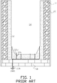
- FIG. 1 illustrates components of a typical electric induction furnace relevant to a replaceable refractory lining used in the furnace.
- Replaceable lining 12 (shown stippled in the figure) consists of a material with a high melting point that is used to line the inside walls of the furnace and form interior furnace volume 14.
- a metal or other electrically conductive material is placed within volume 14 and is heated and melted by electric induction.
- Induction coil 16 surrounds at least a portion of the exterior height of the furnace and an alternating current flowing through the coil creates a magnetic flux that couples with the material placed in volume 14 to inductively heat and melt the material.
- Furnace foundation 18 is formed from a suitable material such as refractory bricks or cast blocks.
- Coil 16 can be embedded in a trowelable refractory (grout) material 20 or other refractory that serves as thermal insulation and protective material for the coil.
- a typical furnace ground leak detector system includes probe wires 22a protruding into melt volume 14 through the bottom of lining 12 as illustrated by wire end 22a' protruding into the melt volume. Wires 22a are connected to electrical ground lead 22b, which is connected to a furnace electrical ground (GND). Wires 22a, or other arrangements used in a furnace ground leak detector system may be generally referred to herein as a ground probe.
- Lining 12 is replenished in a furnace relining process after a point in the service life of the furnace.
- an operator of the furnace may independently decide to delay relining until refractory lining 12 between the molten metal inside furnace volume 14 and coil 16 has deteriorated to the state that furnace coil 16 is damaged and requires repair, and/or foundation 18 has been damaged and requires repair. In such event, the furnace relining process becomes extensive.
- U.S. Patent No. 7,090,801 discloses a monitoring device for melting furnaces that includes a closed circuit consisting of several conductor sections with at least a partially conducting surface and a measuring/displaying device.
- a comb-shaped first conductor section is series connected through an ohmic resistor R to a second conductor section.
- the comb-shaped first conductor section is mounted on the refractory lining and arranged directly adjacent, however, electrically isolated from the second conductor section.
- U.S. Patent No. 6,148,018 discloses an induction melting furnace that includes a detection system for sensing metal penetration into a wall of the furnace depending upon detecting heat flow from the hearth to the furnace.
- An electrode system is interposed between the induction coil and a slip plane material that serves as a backing to the refractory lining.
- the electrode system comprises a sensing mat housing conductors receiving a test signal from the power supply, wherein the sensing mat includes a temperature sensitive binder that varies conductivity between the conductors in response to heat penetration through the lining.
- U.S. Patent No. 5,319,671 discloses a device that has electrodes arranged on the furnace lining.
- the electrodes are divided into two groups of different polarity and are spaced apart from each other.
- the electrode groups can be connected to a device that determines the electrical temperature-dependent resistance of the furnace lining.
- At least one of the electrodes is arranged as an electrode network on a first side on a ceramic foil. Either the first side of the ceramic foil or the opposite side is arranged on the furnace lining.
- the foil in the former case has a lower thermal conductivity and a lower electrical conductivity than the ceramic material of the furnace lining, and in the latter case an approximately identical or higher thermal conductivity and an approximately identical or higher electrical conductivity.
- U.S. Patent No. 1,922,029 discloses a shield that is inserted in the furnace lining to form one contact of a control circuit.
- the shield is made of sheet metal and is bent to form a cylinder. When metal leaks out from the interior of furnace it makes contact with the shield, and the signal circuit is closed.
- U.S. Patent No. 1,823,873 discloses a ground shield that is located within the furnace lining and spaced apart from the induction coil.
- An upper metallic conduit of substantially open annular shape is provided, as is also a similar lower metal conduit also of open annular shape.
- a plurality of relatively smaller metallic pipes or conduits extend between the two larger conduits and are secured thereto in a fluid-tight manner.
- a ground is provided which is connected to the protecting shield.
- US2012/300806A1 discloses a method of fabricating an electric induction furnace with a lining wear detection system, the method comprising the steps of: locating a wound induction coil above a foundation; installing a refractory around the wound induction coil to form a refractory embedded induction coil; positioning a wire assemblage refractory mold within the refractory embedded induction coil to provide a wire assemblage refractory volume between an outer wire assemblage refractory mold wall of the wire assemblage refractory mold and an inner refractory embedded induction coil wall of the refractory embedded induction coil; fitting at least one electrically conductive wire assemblage around the outer wire assemblage refractory mold wall of the wire assemblage refractory mold; providing a wire assemblage refractory into the wire assemblage refractory volume to embed the at least one electrically conductive wire assemblage in the wire assemblage refractory to form an embedded wire assemblage refractory in the wire assemblage refractory volume;
- One object of the present invention is to provide an electric induction furnace with a lining wear detection system that can assist in avoiding furnace coil damage and/or bottom foundation damage due to lining wear when the furnace is properly operated and maintained.
- Another object of the present invention is to provide a method for fabricating an electric induction furnace with a lining wear detection system that utilizes an electrically conductive wire assemblage embedded in a separate wire assemblage refractory.
- the present invention is a method of fabricating an electric induction furnace with a lining wear detection system.
- a wound induction coil is located above a foundation and a refractory is installed around the wound induction coil to form a refractory embedded induction coil.
- a wire assemblage refractory mold is positioned within the refractory embedded induction coil to provide a wire assemblage refractory volume between the outer wire assemblage refractory mold wall of the wire assemblage refractory mold and an inner refractory induction coil wall of the refractory embedded induction coil.
- a temporary top wire assemblage fixture is fitted around the top circumference of the wire assemblage refractory mold and a temporary bottom wire assemblage fixture around the bottom circumference of the wire assemblage refractory mold, each of the temporary top and bottom wire assemblage fixtures having a plurality of circumferential wire insertion notches around the circumference of each of the temporary top and bottom wire assemblage fixtures, each of the plurality of circumferential wire insertion notches having a wire turn sub-notch.
- At least one electrically conductive wire assemblage is fitted around the outer wire assemblage refractory mold wall of the wire assemblage refractory mold, the at least one electrically conductive wire assemblage comprising at least one continuous wire, the at least one continuous wire vertically weaved at least partially around the height of the outer circumference of the temporary top and bottom wire assemblage fixtures by sequential insertion of the single continuous wire within the wire turn notch of each circumferential wire insertion notches of the temporary top and bottom wire assemblage fixtures.
- a wire assemblage refractory is provided into the wire assemblage refractory volume to embed the at least one electrically conductive wire assemblage in the wire assemblage refractory to form an embedded wire assemblage refractory in the wire assemblage refractory volume.
- the wire assemblage refractory mold and the temporary top and bottom wire assemblage fixtures are removed to form an interior wire assemblage refractory furnace volume, and a replaceable lining mold is positioned within the interior of the wire assemblage refractory furnace volume to form a replaceable lining wall volume between outer replaceable lining mold wall of the replaceable lining mold and an inner embedded wire assemblage refractory wall of the embedded wire assemblage refractory, and a replaceable lining bottom volume above the foundation.
- a replaceable lining refractory is fed into the replaceable lining wall volume and the replaceable lining bottom volume, and the replaceable lining mold is removed to form an interior volume of the electric induction furnace.
- Embodiments encompassing a "mesh" lining wear detection system do not form a part of the invention and represent background art that is useful for understanding the invention where a "wire" assemblage lining wear detection system is used optionally in combination with a furnace bottom mesh lining wear detection system.
- FIG. 2 there is shown in FIG. 2 one example of an electric induction furnace 10 with a lining wear detection system.
- a cast flowable refractory 24 is disposed between coil 16 and replaceable furnace lining 12.
- electrically conductive mesh 26, (for example, a stainless steel mesh) is embedded within the inner boundary of castable refractory 24 that is adjacent to the outer boundary of lining 12.
- a suitable mesh is formed from type 304 stainless steel welded wire cloth with mesh size 4 x 4; wire diameter between 711.2 - 812.8 ⁇ m (0.028-0.032-inch); and opening width of 5.64 - 5.54 mm (0.222-0.218-inch).
- FIG. 2 one example of an electric induction furnace 10 with a lining wear detection system.
- a cast flowable refractory 24 is disposed between coil 16 and replaceable furnace lining 12.
- electrically conductive mesh 26 for example, a stainless steel mesh
- One non-limiting example of a suitable mesh is formed from type 304 stainless steel welded wire cloth with mesh
- mesh 26 forms a discontinuous cylindrical mesh boundary between castable refractory 24 and lining 12 from the top (26 TOP ) to the bottom (26 BOT ) of the outer boundary of the lining wall.
- One vertical side 26a of mesh 26 is suitably connected to a positive electric potential that can be established by a suitable voltage source, such as direct current (DC) voltage source V c that has its other terminal connected to furnace electrical ground (GND).
- a lining wear detection circuit is formed between the positive electric potential connected to the electrically conductive mesh and the negative electric potential connected to the furnace electrical ground.
- Vertical discontinuity 26c (along the height of the lining in this example) in mesh 26 is sized to prevent short circuiting between opposing vertical sides 26a and 26b of mesh 26.
- the mesh may be fabricated in a manner so that the mesh is electrically isolated from itself; for example, a layer of electrical insulation can be provided between two overlapping ends (sides 26a and 26b in this example) of the mesh.
- the voltage source circuit can be connected to control and/or indicating circuits via suitable circuit elements such as a current transformer.
- the control and/or indicating circuits are referred to collectively as a detector.
- a leakage current rise level set point can be established for indication of lining replacement when the furnace is properly operated and maintained.
- a bottom lining wear detection system may be provided as shown, for example in FIG. 4 , in addition to the wall lining wear detection system shown in FIG. 2 .
- electrically conductive bottom mesh 30 is disposed within cast flowable refractory 28 with bottom mesh 30 adjacent to the lower boundary of lining 12 at the bottom of the furnace.
- bottom mesh 30 forms a discontinuous circular mesh boundary between bottom cast flowable refractory 28 and the bottom of lining 12.
- the bottom mesh boundary may be formed from a continuous circular mesh 30' as shown in FIG. 5(b) between bottom cast flowable refractory 28 and the bottom of lining 12.
- discontinuous radial side 30a of bottom mesh 30 is suitably connected to a positive electric potential established by a suitable voltage source V' dc that has its other terminal connected to furnace electrical ground (GND).
- V' dc that has its other terminal connected to furnace electrical ground (GND).
- a bottom lining wear detection circuit is formed between the positive electric potential connected to the electrically conductive bottom mesh and the negative electric potential connected to the furnace electrical ground.
- radial discontinuity 30c in mesh 30 is sized to prevent short circuiting between opposing radial sides 30a and 30b of mesh 30.
- the mesh may be fabricated in a manner so that the mesh is electrically isolated from itself; for example, a layer of electrical insulation can be provided between two overlapping ends (radial sides 30a and 30b in this example) of the mesh. As shown in FIG.
- the bottom lining wear detection circuit can be connected to a bottom lining wear control and/or indicating circuits, which are collectively referred to as a detector.
- a leakage current rise level set point can be established for indication of lining replacement, based on bottom lining wear, when the furnace is properly operated and maintained.
- discontinuous side wall and bottom meshes are one example of discontinuous mesh arrangements when required in a particular application.
- the purpose for the discontinuity is to prevent eddy current heating of the mesh when required from inductive coupling with the magnetic flux generated when alternating current is flowing through induction coil 16 when the coil is connected to a suitable alternating current power source during operation of the furnace. Therefore other arrangements of side wall and bottom meshes are acceptable as long as the mesh arrangement prevents such inductive heating of the mesh when required in a particular application.
- arrangement of the electrical connection(s) of the mesh to the lining wear detection circuit, and the control and/or indicating circuits can vary depending upon a particular furnace design. Depending upon the physical arrangement of a particular electric induction furnace continuous bottom and/or side wall meshes may be satisfactory without excessive eddy current heating.
- refractory embedded wall mesh 26 may extend for the entire vertical height of lining 12, that is, from the bottom (12 BOT ) of the furnace lining to the very top (12 TOP ) of the furnace lining that is above the nominal design melt line 25 for a particular furnace as shown, for example, in FIG. 8 .
- wall mesh 26 may be provided in one or more selected discrete regions along the vertical height of lining 12.
- wall mesh comprises two vertical electrically conductive meshes 36a and 36b that are electrically isolated from each other and connected to separate lining wear detection circuits so that lining wear can be diagnosed as being on either one half side of the furnace lining.
- any multiple of separate, vertically oriented and electrically isolated wall mesh regions may be provided along the vertical height of lining 12 with each separate wall mesh region being connected to a separate lining wear detection circuit so that lining wear could be localized to one of the wall mesh regions.
- the multiple electrically conductive meshes 46a through 46d can be horizontally oriented with each electrically isolated mesh connected to a separate lining wear detection circuit and control and/or indicating circuits (D) so that lining wear can be localized to one of the isolated mesh regions.
- D control and/or indicating circuits
- the multiple electrically conductive meshes 56a through 56p can be arrayed around the height of the replaceable lining wall with each electrically conductive mesh connected to a separate lining wear detection circuit, and control and/or indicating circuits (not shown in the figure) so that lining wear can be localized to one of the isolated mesh regions that can be defined by a two-dimensional X-Y coordinate system around the circumference of the replaceable lining wall with the X coordinate defining a position around the circumference of the lining and the Y coordinate defining a position along the height of the lining.
- bottom mesh 30 may cover less than the entire bottom of replaceable lining 12 in some examples, or comprise a number of electrically isolated bottom meshes with each of the electrically isolated bottom meshes connected to a separate lining wear detection circuit so that lining wear could be localized to one of the bottom mesh regions.
- a single detector can be switchably connected to the lining wear detection circuits associated with two or more of the electrically isolated meshes.
- a combined wall and bottom lining wear detection system may be provided either by (1) providing a continuous side and bottom mesh embedded in an integrally cast flowable refractory with a single lining wear detection circuit and detector or (2) providing separate side and bottom meshes embedded in a cast flowable refractory with a common lining wear detection circuit and detector.
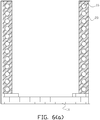
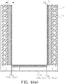
- FIG. 6(a) through FIG. 6(f) illustrate one example of fabrication of an electric induction furnace with a lining wear detection system.
- Induction coil 16 can be fabricated (typically wound) and positioned over suitable foundation 18.
- trowelable refractory (grout) material 20 or other refractory, can be installed around the coil as in the prior art.
- INDUCTOCOATTM 35AF available from Inductotherm Corp., Rancocas, New Jersey.
- bottom mesh 30 can be fitted at the top of foundation 18 and embedded in cast flowable refractory by pouring the cast flowable refractory around bottom mesh 30 so that the mesh is embedded within the refractory after it sets as shown in FIG. 6(b) .
- the bottom mesh can be cast in a cast flowable refractory 28 in a separate mold and then the cast refractory embedded bottom mesh can be installed in the bottom of the furnace after the cast flowable refractory sets.
- a suitable temporary cast flowable refractory mold 90 (or molds forming a formwork) for example, in the shape of an open right cylinder, is positioned within the volume formed by coil 16 and refractory material 20 to form a cast flowable refractory annular volume between refractory material 20 and the outer wall perimeter of the mold as shown in FIG. 6(c) .
- Mesh 26 is fitted around the outer perimeter of temporary mold 90 and the cast flowable refractory 24, such as INDUCTOCOATTM 35AF-FLOW (available from Inductotherm Corp., Rancocas, New Jersey), can be poured into the cast flowable refractory annular volume to set and form hardened castable refractory 24 as shown in FIG. 6(e) .
- Vibrating compactors can be used to release trapped air and excess water from the cast flowable refractory so that the refractory settles firmly in place in the formwork before setting.
- Mesh 26 will be at least partially embedded in cast flowable refractory 24 when it sets inside of the cast flowable refractory annular volume.
- mesh 26 can be embedded anywhere within the thickness, t, of cast flowable refractory 24.
- mesh 26 is offset by distance, t 1 , from the inner wall perimeter of cast flowable refractory 24. Offset embedment can be achieved by installing suitable standoffs 91 around the outer perimeter of mold 90 as shown in FIG.
- mesh 26 in a cast flowable refractory is understood as the mesh is either fixed within the refractory; at a surface boundary of the refractory, or sufficiently, but not completely, embedded at a surface boundary of the refractory so that the mesh is retained in place in the refractory after the refractory sets.
- a replaceable lining mold 92 that is shaped to conform to the boundary wall and bottom of interior furnace volume 14 can be positioned within the volume formed by set cast flowable refractory 24 (with embedded mesh 26) to form a replaceable lining annular volume between set cast flowable refractory 24 and the outer wall perimeter of the lining mold 92 as shown in FIG. 6(f) .
- a conventional powdered refractory can then be fed into the lining volume according to conventional procedures. If lining mold 92 is formed from an electrically conductive mold material, lining mold 92 can be heated and melted in place according to conventional procedures to sinter the lining refractory layer that forms the boundary of furnace volume 14. Alternatively the lining mold may be removed and sintering of the lining refractory layer may be accomplished by direct heat application.
- Distinction is made between the replaceable lining refractory, which is typically a powdered refractory and the cast flowable refractory in which the electrically conductive mesh is embedded.
- the cast flowable refractory is preferably used so that the electrically conductive mesh can be embedded in the refractory.
- the cast flowable refractory is also referred to herein as castable refractory and flowable refractory.
- FIG. 6(g) illustrates an electric induction furnace with one example of a lining wear detection system with addition of typical furnace ground leak detector system probe wires 22a and electrical ground lead 22b that is connected to a furnace electrical ground (GND).
- GND furnace electrical ground
- FIG. 6(a) through FIG. 6(g) illustrates one example of fabrication steps of an electric induction furnace with a lining wear detection system. Additional conventional fabrication steps may be required to complete furnace construction.
- FIG. 10 There is shown in FIG. 10 one example of an electric induction furnace 11 with a lining wear detection system.
- a wall refractory 23 is disposed between coil 16 and replaceable furnace lining 12 and is also referred to as wire assemblage refractory 23.
- the wall refractory may be a castable or trowelable refractory.
- electrically conductive wire assemblage 27 is embedded within the inner boundary of wall refractory 23 that is adjacent to the outer boundary of lining 12, and wall refractory 23 is also referred to as the wire assemblage refractory.
- a suitable electrically conductive wire assemblage is formed from an assemblage of stainless or copper nickel stranded wire in a range from 18 to 10 AWG depending upon the particular configuration of the induction furnace. In other arrangements of the invention other types of electrically conductive wire may be used as suitable for a particular application.
- the wire may be bare or insulated if arcing is an issue in a particular application.
- Stranded wire is preferred although solid wire may be used in some applications. As shown in FIG.
- electrically conductive wire assemblage 27 forms a vertical wire cage between wire assemblage refractory 23 and consumable lining 12 from the top (26 TOP ) to the bottom (26 BOT ) of the outer boundary of the replaceable lining wall to separate the replaceable lining wall 12 from induction coil 16.
- twenty-six vertical wires 27 1 to 27 26 are vertically spaced apart from each other around the circumference of wire assemblage refractory 23.
- the twenty-six vertically oriented wires are electrically connected together by suitable electrically connecting means such as a collector wire 29 formed from multiple tap connecters or wire lugs 31 to a bottom collector wire of electrically conductive wire assemblage 27 in this example of the invention.
- suitable electrically connecting means such as a collector wire 29 formed from multiple tap connecters or wire lugs 31 to a bottom collector wire of electrically conductive wire assemblage 27 in this example of the invention.
- riser protection wires More generally the number of vertical wires used depends upon the configuration of a particular induction furnace and are referred to as riser protection wires. While vertically-oriented riser protection wires are shown in the above example of the invention, in other examples the arrangement of riser protection wires around the circumference of wire assemblage refractory 23 may be of other configurations such as a spiral configuration. While a bottom collector wire is used in the above example of the invention the collector wire may be located anywhere between the top and bottom ends of the riser protection wires and there may be more than one collector wire depending upon a particular application.
- collector wire 29 is connected at a single terminal point T 1 to a positive electric potential that can be established by a suitable voltage source, such as direct current (DC) voltage source V dc that has its other (negative) terminal connected to furnace electrical ground (GND).
- a suitable voltage source such as direct current (DC) voltage source V dc that has its other (negative) terminal connected to furnace electrical ground (GND).
- a lining wear detection circuit is formed between the positive electric potential connected to electrically conductive wire assemblage 27 and the negative electric potential connected to the furnace electrical ground.
- the voltage source circuit can be connected to control circuits and/or indicating circuits via suitable circuit elements such as a current transformer.
- suitable direct measurement of leakage current can be provided with suitable direct measurement device such as, but not limited to, a current shunt resistor.
- the control and/or indicating circuits are referred to collectively as a detector.
- a leakage current rise level set point can be established for indication of lining replacement when the furnace is properly operated and maintained.
- FIG. 12(a) illustrates an alternative to the protective riser wires shown in FIG. 11(a) .
- a single continuous riser wire 35 which is also referred to as a protective riser wire 35, is provided by weaving the riser wire around the top and bottom circumferences of the induction furnace.
- Top wire assemblage fixture (fitting) 51 as shown in FIG. 12(b) and FIG. 12(c) is used to facilitate weaving the single continuous wire 35.
- Fixture 51 is generally cylindrical in shape and has top wire turn notches 51' that facilitate turn of the continuous riser wire 35 at the top of the furnace during installation.
- Each wire turn notch 51' comprises a generally semicircular cutout volume as seen in cross section in FIG.
- each wire seating sub-notch 51" has a cross sectional diameter slightly larger than the cross sectional diameter of wire 35. Off-centering of wire seating sub-notch 51" in the direction of the top-to-bottom weave (illustrated by the arrow in FIG. 12(c) ) assists in making the turn of the riser wire 180 degrees from the upward to downward direction at the top of the furnace.
- a bottom wire assemblage fixture (fitting) 52 as shown in FIG. 12(e) is provided to facilitate weaving of the continuous riser wire 35 at the bottom of the induction furnace being assembled.
- Bottom fixture 52 is similar to top fixture 51 rotated 180 degrees as shown in the figures with complementary arranged bottom wire turn notches 52' and wire seating sub-notches 52".
- the top and bottom fixtures are temporarily positioned respectively at, or adjacent to, the top and bottom of the wire assemblage refractory when used during the fabrication of an electric induction furnace.
- a bottom lining wear detection system may be provided as alternatively shown, for example in FIG. 14(a), 14(b) or 14(c) , in addition to one of the wall lining wear detection systems shown in FIG. 11(a) and FIG. 11(b) .
- electrically conductive discontinuous bottom mesh 30; continuous bottom mesh 30'; or wire assemblage 30" is disposed within bottom refractory 28 with bottom mesh 30 adjacent to the lower boundary of lining 12 at the bottom of the furnace.
- bottom mesh 30 forms an electrically discontinuous circular mesh boundary between bottom refractory 28 and the bottom of lining 12.
- the bottom mesh boundary may be formed from a continuous circular mesh 30' as shown in FIG.
- the electrically discontinuous bottom mesh 30 is used, at least one discontinuous radial side 30a of bottom mesh 30 is suitably connected to a positive electric potential established by a suitable voltage source V' dc that has its other terminal connected to furnace electrical ground (GND).
- a bottom lining wear detection circuit is formed between the positive electric potential connected to the electrically conductive bottom mesh or wire assemblage and the negative electric potential connected to the furnace electrical ground.
- the at least one radial electrical discontinuity 30c in mesh 30 is sized to prevent short circuiting between opposing radial sides 30a and 30b of mesh 30 and may include multiple discontinuities 30c, 30c' and 30c" as shown in FIG. 14(a) when required for a particular application.
- the bottom mesh boundary may be formed from a continuous circular mesh 30' as shown in FIG. 14(b) between bottom cast flowable refractory 28 and the bottom of lining 12, or one or more electrically conductive wire assemblage 30" as shown in FIG. 14(c) .
- the mesh may be fabricated in a manner so that the mesh is electrically isolated from itself. As shown in the alternative arrangements of FIG. 14(a), FIG. 14(b) and FIG.
- the bottom lining wear detection circuit can be connected to a bottom lining wear control and/or indicating circuits, which are collectively referred to as a detector.
- a leakage current rise level set point can be established for indication of lining replacement, based on bottom lining wear, when the furnace is properly operated and maintained.
- electrically conductive wire assemblage 27 or 35 may extend for the entire vertical height of lining 12, that is, from the bottom (12 BOT ) of the furnace lining to the very top (12 TOP ) of the furnace lining that is above the nominal design melt line 25 for a particular furnace as shown, for example, in FIG. 17 for electrically conductive wire assemblage 27.
- electrically conductive wire assemblage 27 may be provided in one or more selected discrete regions along the vertical height of lining 12.
- the electrically conductive wire assemblage comprises two vertical electrically conductive wire assemblages 53a and 53b that are electrically isolated from each other and connected to separate lining wear detection circuits so that lining wear can be sensed as being on either one half side of the furnace lining.
- any multiple of separate, vertically oriented and electrically isolated wall electrically conductive wire assemblage regions may be provided along the vertical height of lining 12 with each separate wall region being connected to a separate lining wear detection circuit so that lining wear could be localized to one of the wall regions.
- each electrically isolated electrically conductive wire assemblage connected to a separate lining wear detection circuit and control and/or indicating circuits (D) so that lining wear can be localized to one of the isolated wire assemblage regions.
- One or more of the vertical risers may be oriented in different directions.
- wire assemblage 55a at the top of the furnace in FIG. 18(b) has the protection wires oriented with horizontal while wire assemblages 55b, 55c and 55d are vertically oriented.
- wire assemblages 55b, 55c and 55d are vertically oriented.
- the multiple electrically conductive wire assemblage 59a through 59p can be arrayed around the height of the replaceable lining wall with each electrically conductive wire assemblage connected to a separate lining wear detection circuit (D) with control and/or indicating circuit so that lining wear can be localized to one of the isolated electrically conductive wire assemblage regions that can be defined by a two-dimensional X-Y coordinate system around the circumference of the replaceable lining wall with the X (horizontal) coordinate defining a position around the circumference of the lining and the Y (vertical) coordinate defining a position along the height of the lining.
- D lining wear detection circuit
- discontinuous mesh 30, continuous mesh 30' or wire assemblage 30" may cover less than the entire bottom of replaceable lining 12 in some examples , or comprise a number of electrically isolated bottom meshes or wire assemblages with each of the electrically isolated bottom meshes or wire assemblages connected to a separate lining wear detection circuit so that lining wear could be localized to one of the bottom mesh or wire assemblage regions.
- a single detector can be switchably connected to the lining wear detection circuits associated with two or more of the electrically conductive meshes or wire assemblages in all examples.
- a combined wall electrically conductive wire assemblage and bottom lining wear detection system may be provided either by (1) providing a continuous side electrically conductive wire assemblage and bottom mesh or wire assemblage embedded in a refractory with a single lining wear detection circuit and detector or (2) providing separate side electrically conductive wire assemblage and bottom meshes or wire assemblages embedded in a refractory with a common lining wear detection circuit and detector.
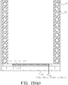
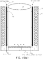
- FIG. 15(a) through FIG. 15(h) illustrate examples of the fabrication of an electric induction furnace with a lining wear detection system of the present invention with a side electrically conductive wire assemblage.
- Induction coil 16 can be fabricated (typically wound) and positioned over suitable foundation 18.
- trowelable refractory (grout) material 20 or other suitable refractory, can be installed around the coil as in the prior art.
- INDUCTOCOATTM 35AF available from Inductotherm Corp., Rancocas, New Jersey.
- an alternative discontinuous or continuous bottom mesh 30 or 30', or wire assemblage 30" can be fitted at the top of foundation 18 and embedded in a bottom refractory, for example, a cast flowable refractory by pouring the cast flowable refractory around the selected bottom mesh or wire assemblage so that the mesh or wire assemblage is embedded within the refractory after it sets as shown in FIG. 15(b) .
- the bottom mesh or wire assemblage can be cast in refractory 28 in a separate mold and then the cast refractory embedded bottom mesh or wire assemblage can be installed in the bottom of the furnace after the cast flowable refractory sets.
- a suitable temporary cast flowable refractory mold 90 (or molds forming a formwork) for example, in the shape of an open right cylinder, is positioned within the volume formed by coil 16 and refractory material 20 to form a wire assemblage refractory annular volume between refractory material 20 and the outer wall perimeter of the mold as shown in FIG. 15(c) .
- Mold 90 is also referred to as the wire assemblage refractory mold.
- wire assemblage refractory 23 such as INDUCTOCOATTM 35AF-FLOW (available from Inductotherm Corp., Rancocas, New Jersey), can be supplied to the wire assemblage refractory annular volume to set and form hardened wire assemblage refractory 23 as shown in FIG. 15(f) .
- INDUCTOCOATTM 35AF-FLOW available from Inductotherm Corp., Rancocas, New Jersey
- temporary top wire assemblage fixture (or fitting) 51 is positioned at the top, or adjacent to the top, of temporary mold 90 in FIG. 15(d) .
- a temporary bottom wire assemblage fixture (or fitting) 52 is positioned at the bottom, or adjacent to the bottom, of temporary mold 90 and continuous electrically conductive wire 35 is weaved vertically around the outer circumference of the temporary mold in this example of the invention by using the top and bottom fittings as further illustrated in FIG. 12(d) which temporary fittings are removed after wire 35 is weaved.
- One continuous wire 35 may be weaved around the entire circumference of the temporary mold or two or more continuous wires may be used to complete a weave around the entire circumference.
- An alternative method of forming the electrically conductive wire assemblage 27 in FIG. 11(a) is to weave continuous electrically conductive wire 35 shown in FIG. 12(a) vertically around the outer circumference of temporary mold 90 as described in the previous paragraph and then cut off all the top loops 35a and bottom loops 35b shown in FIG. 12(a) of the continuous electrically conductive wire to form the riser wires 27 1 to 27 26 in FIG. 11(a) ; the riser wires are then connected together, for example, at the bottom of the induction furnace with a collector wire 29 to form the electrically conductive wire assemblage 27 shown in FIG. 11(a) .
- Vibrating compactors can be used to release trapped air and excess water from a cast flowable refractory (if used) so that the wire assemblage refractory settles firmly in place in the formwork before setting. Electrically conductive wire assemblage 27 or 35 will be at least partially embedded in wire assemblage refractory 23 when it sets inside of the wire assemblage refractory annular volume.
- electrically conductive wire assemblage 27 or 35 can be embedded anywhere within the thickness, t, of cast flowable refractory 24.
- electrically conductive wire assemblage 27 is offset by distance, t 1 , from the inner wall perimeter of wire assemblage refractory 23. Offset embedment can be achieved by installing suitable standoffs 91 around the outer perimeter of mold 90 as shown in FIG. 15(e) and then fitting electrically conductive wire assemblage 27 around the standoffs before providing the wire assemblage refractory.
- mesh or wire assemblage "embedded" in a refractory is used to indicate that the mesh or wire assemblage is either fixed within the refractory; at a surface boundary of the refractory, or sufficiently, but not completely, embedded at a surface boundary of the refractory so that the mesh or wire assemblage is retained in place in the refractory after the refractory sets.
- a replaceable lining mold 92 that is shaped to conform to the boundary wall and bottom of interior furnace volume 14 can be positioned within the volume formed by set wire assemblage refractory 23 (with embedded wire assemblage 27) to form a replaceable lining annular volume between set cast flowable refractory 23 and the outer wall perimeter of the lining mold 92 as shown in FIG. 15(g) .
- a conventional powdered refractory for example, can then be fed into the lining volume according to conventional procedures.
- lining mold 92 is formed from an electrically conductive mold material, lining mold 92 can be heated and melted in place according to conventional procedures to sinter the lining refractory layer that forms the boundary of furnace volume 14. Alternatively the lining mold may be removed and sintering of the lining refractory layer may be accomplished by direct heat application.
- Distinction is made between the replaceable lining refractory, which is typically a powdered refractory and the cast flowable refractory in which the electrically conductive mesh or wire assemblage is typically embedded.
- the cast flowable refractory is preferably used so that the electrically conductive mesh or wire assemblage can be embedded in the refractory.
- the cast flowable refractory is also referred to herein as castable refractory and flowable refractory.
- FIG. 15(h) illustrates an electric induction furnace with one example of a lining wear detection system of the present invention with side wire assemblage 27 addition of typical furnace ground leak detector system probe wires 22a and electrical ground lead 22b that is connected to a furnace electrical ground (GND).
- GND furnace electrical ground
- FIG. 15(a) through FIG. 15(h) illustrate non-limiting examples of fabrication steps exemplary to the present invention. Additional conventional fabrication steps may be required to complete furnace construction.
- cast flowable refractory 24 can be extended to, and around coil 16.
- the induction furnace of the present invention may be of any type, for example, a bottom pour, top tilt pour, pressure pour, or push-out electric induction furnace, operating at atmosphere or in a controlled environment such as an inert gas or vacuum. While the induction furnace shown in the figures has a circular interior cross section, furnaces with other cross sectional shapes, such as square, may also utilize the present invention. While a single induction coil is shown in the drawing for the electric induction furnace of the present invention, the term "induction coil” as used herein also includes a plurality of induction coils either with individual electrical connections and/or electrically interconnected induction coils.
- lining wear detection system of the present invention may also be utilized in portable refractory lined ladles used to transfer molten metals between locations and stationary refractory lined launders.
Landscapes
- Engineering & Computer Science (AREA)
- Mechanical Engineering (AREA)
- General Engineering & Computer Science (AREA)
- Physics & Mathematics (AREA)
- Electromagnetism (AREA)
- Power Engineering (AREA)
- Waste-Gas Treatment And Other Accessory Devices For Furnaces (AREA)
- Furnace Housings, Linings, Walls, And Ceilings (AREA)
- General Induction Heating (AREA)
- Measurement Of Length, Angles, Or The Like Using Electric Or Magnetic Means (AREA)
- Crucibles And Fluidized-Bed Furnaces (AREA)
- Vertical, Hearth, Or Arc Furnaces (AREA)
- Furnace Details (AREA)
Description
- The present invention relates to electric induction furnaces, and in particular, to detecting the wear of furnace linings in electric induction furnaces.
-
FIG. 1 illustrates components of a typical electric induction furnace relevant to a replaceable refractory lining used in the furnace. Replaceable lining 12 (shown stippled in the figure) consists of a material with a high melting point that is used to line the inside walls of the furnace and forminterior furnace volume 14. A metal or other electrically conductive material is placed withinvolume 14 and is heated and melted by electric induction.Induction coil 16 surrounds at least a portion of the exterior height of the furnace and an alternating current flowing through the coil creates a magnetic flux that couples with the material placed involume 14 to inductively heat and melt the material. Furnacefoundation 18 is formed from a suitable material such as refractory bricks or cast blocks.Coil 16 can be embedded in a trowelable refractory (grout)material 20 or other refractory that serves as thermal insulation and protective material for the coil. A typical furnace ground leak detector system includesprobe wires 22a protruding intomelt volume 14 through the bottom oflining 12 as illustrated bywire end 22a' protruding into the melt volume.Wires 22a are connected toelectrical ground lead 22b, which is connected to a furnace electrical ground (GND).Wires 22a, or other arrangements used in a furnace ground leak detector system may be generally referred to herein as a ground probe. - As the furnace is used for repeated melts within
volume 14,lining 12 is gradually consumed.Lining 12 is replenished in a furnace relining process after a point in the service life of the furnace. Although it is contrary to safe furnace operation and disregards the recommendation of the refractory manufacturer and installer, an operator of the furnace may independently decide to delay relining untilrefractory lining 12 between the molten metal insidefurnace volume 14 andcoil 16 has deteriorated to the state thatfurnace coil 16 is damaged and requires repair, and/orfoundation 18 has been damaged and requires repair. In such event, the furnace relining process becomes extensive. -
U.S. Patent No. 7,090,801 discloses a monitoring device for melting furnaces that includes a closed circuit consisting of several conductor sections with at least a partially conducting surface and a measuring/displaying device. A comb-shaped first conductor section is series connected through an ohmic resistor R to a second conductor section. The comb-shaped first conductor section is mounted on the refractory lining and arranged directly adjacent, however, electrically isolated from the second conductor section. -
U.S. Patent No. 6,148,018 discloses an induction melting furnace that includes a detection system for sensing metal penetration into a wall of the furnace depending upon detecting heat flow from the hearth to the furnace. An electrode system is interposed between the induction coil and a slip plane material that serves as a backing to the refractory lining. The electrode system comprises a sensing mat housing conductors receiving a test signal from the power supply, wherein the sensing mat includes a temperature sensitive binder that varies conductivity between the conductors in response to heat penetration through the lining. -
U.S. Patent No. 5,319,671 discloses a device that has electrodes arranged on the furnace lining. The electrodes are divided into two groups of different polarity and are spaced apart from each other. The electrode groups can be connected to a device that determines the electrical temperature-dependent resistance of the furnace lining. At least one of the electrodes is arranged as an electrode network on a first side on a ceramic foil. Either the first side of the ceramic foil or the opposite side is arranged on the furnace lining. The foil in the former case has a lower thermal conductivity and a lower electrical conductivity than the ceramic material of the furnace lining, and in the latter case an approximately identical or higher thermal conductivity and an approximately identical or higher electrical conductivity. -
U.S. Patent No. 1,922,029 discloses a shield that is inserted in the furnace lining to form one contact of a control circuit. The shield is made of sheet metal and is bent to form a cylinder. When metal leaks out from the interior of furnace it makes contact with the shield, and the signal circuit is closed. -
U.S. Patent No. 1,823,873 discloses a ground shield that is located within the furnace lining and spaced apart from the induction coil. An upper metallic conduit of substantially open annular shape is provided, as is also a similar lower metal conduit also of open annular shape. A plurality of relatively smaller metallic pipes or conduits extend between the two larger conduits and are secured thereto in a fluid-tight manner. A ground is provided which is connected to the protecting shield. -
US2012/300806A1 discloses a method of fabricating an electric induction furnace with a lining wear detection system, the method comprising the steps of: locating a wound induction coil above a foundation; installing a refractory around the wound induction coil to form a refractory embedded induction coil; positioning a wire assemblage refractory mold within the refractory embedded induction coil to provide a wire assemblage refractory volume between an outer wire assemblage refractory mold wall of the wire assemblage refractory mold and an inner refractory embedded induction coil wall of the refractory embedded induction coil; fitting at least one electrically conductive wire assemblage around the outer wire assemblage refractory mold wall of the wire assemblage refractory mold; providing a wire assemblage refractory into the wire assemblage refractory volume to embed the at least one electrically conductive wire assemblage in the wire assemblage refractory to form an embedded wire assemblage refractory in the wire assemblage refractory volume; removing the wire assemblage refractory mold to form an interior wire assemblage refractory furnace volume; positioning a replaceable lining mold within the interior of the wire assemblage refractory furnace volume to form a replaceable lining wall volume between an outer replaceable lining mold wall of the replaceable lining mold and an inner embedded wire assemblage refractory wall of the embedded wire assemblage refractory, and a replaceable lining bottom volume above the foundation; feeding a replaceable lining refractory into the replaceable lining wall volume and the replaceable lining bottom volume; and removing the replaceable lining mold to form an interior volume of the electric induction furnace. - One object of the present invention is to provide an electric induction furnace with a lining wear detection system that can assist in avoiding furnace coil damage and/or bottom foundation damage due to lining wear when the furnace is properly operated and maintained.
- Another object of the present invention is to provide a method for fabricating an electric induction furnace with a lining wear detection system that utilizes an electrically conductive wire assemblage embedded in a separate wire assemblage refractory.
- In one aspect, the present invention is a method of fabricating an electric induction furnace with a lining wear detection system. A wound induction coil is located above a foundation and a refractory is installed around the wound induction coil to form a refractory embedded induction coil. A wire assemblage refractory mold is positioned within the refractory embedded induction coil to provide a wire assemblage refractory volume between the outer wire assemblage refractory mold wall of the wire assemblage refractory mold and an inner refractory induction coil wall of the refractory embedded induction coil. A temporary top wire assemblage fixture is fitted around the top circumference of the wire assemblage refractory mold and a temporary bottom wire assemblage fixture around the bottom circumference of the wire assemblage refractory mold, each of the temporary top and bottom wire assemblage fixtures having a plurality of circumferential wire insertion notches around the circumference of each of the temporary top and bottom wire assemblage fixtures, each of the plurality of circumferential wire insertion notches having a wire turn sub-notch. At least one electrically conductive wire assemblage is fitted around the outer wire assemblage refractory mold wall of the wire assemblage refractory mold, the at least one electrically conductive wire assemblage comprising at least one continuous wire, the at least one continuous wire vertically weaved at least partially around the height of the outer circumference of the temporary top and bottom wire assemblage fixtures by sequential insertion of the single continuous wire within the wire turn notch of each circumferential wire insertion notches of the temporary top and bottom wire assemblage fixtures. A wire assemblage refractory is provided into the wire assemblage refractory volume to embed the at least one electrically conductive wire assemblage in the wire assemblage refractory to form an embedded wire assemblage refractory in the wire assemblage refractory volume. The wire assemblage refractory mold and the temporary top and bottom wire assemblage fixtures are removed to form an interior wire assemblage refractory furnace volume, and a replaceable lining mold is positioned within the interior of the wire assemblage refractory furnace volume to form a replaceable lining wall volume between outer replaceable lining mold wall of the replaceable lining mold and an inner embedded wire assemblage refractory wall of the embedded wire assemblage refractory, and a replaceable lining bottom volume above the foundation. A replaceable lining refractory is fed into the replaceable lining wall volume and the replaceable lining bottom volume, and the replaceable lining mold is removed to form an interior volume of the electric induction furnace.
- The figures, in conjunction with the specification and claims, illustrate one or more non-limiting modes of practicing the invention. The invention is not limited to the illustrated layout and content of the drawings.
-
FIG. 1 is a simplified cross sectional diagram of one example of an electric induction furnace. -
FIG. 2 is a cross sectional diagram of one example of an electric induction furnace with a lining wear detection system. -
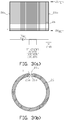
FIG. 3(a) illustrates in flat planar view one example of an electrically conductive mesh, a lining wear detection circuit, and a control and/or indicating (detector) circuit used in the electric induction furnace shown inFIG. 2 -
FIG. 3(b) illustrates in top plan view the electrically conductive mesh shown inFIG. 3(a) in the shape as installed around the circumference of the electric induction furnace shown inFIG. 2 . -
FIG. 4 is a cross sectional diagram of another example of an electric induction furnace with a lining wear detection system that includes a bottom electrically conductive mesh. -
FIG. 5(a) and 5(b) illustrate in top plan view alternative bottom electrically conductive mesh, bottom lining wear detection circuit, and control and/or indicating (detector) circuit used for bottom lining wear detection. -
FIG. 6(a) through FIG. 6(g) illustrate fabrication of one example of an electric induction furnace with a lining wear detection system. -
FIG. 7 is a detail of one example of the electrically conductive mesh embedded in a cast flowable refractory used in an electric induction furnace with a lining wear detection system. -
FIG. 8 is a cross sectional diagram of another example of an electric induction furnace with a lining wear detection system. -
FIG. 9(a) through FIG. 9(d) illustrate alternative arrangements of electrically conductive mesh, lining wear detection circuits and detectors used in the electric induction furnace with a lining wear detection system. -
FIG. 10 is a cross sectional diagram of one example of an electric induction furnace with a lining wear detection system that uses an electrically conductive wire assemblage embedded in a wire assemblage embedded refractory. -
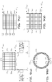
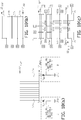
FIG. 11(a) illustrates in flat planar view one example of an electrically conductive wire assemblage, a lining wear detection circuit, and a control and/or indicating (detector) circuit used in the electric induction furnace shown inFIG. 10 . -
FIG. 11(b) illustrates in top plan view the electrically conductive wire assemblage shown inFIG. 11(a) embedded in the wire assemblage refractory in the shape as installed around the circumference of the electric induction furnace shown inFIG. 10 . -
FIG. 12(a) illustrates in flat planar view another example of an electrically conductive wire assemblage, a lining wear detection circuit, and a control and/or indicating (detector) circuit that can be used in the furnace volume shown inFIG. 10 . -
FIG. 12(b) illustrates in top plan view one example of a fixture that is used to install the electrically conductive wire assemblage shown inFIG. 12(a) around the top circumference of the electric induction furnace shown inFIG. 10 . -
FIG. 12(c) illustrates in partial elevation view one example of the fixture shown inFIG. 12(b) . -
FIG. 12(d) illustrates in partial elevation view one example of weaving a continuous electrically conductive wire assemblage around the fixture shown inFIG. 12(b) . -
FIG. 12(e) illustrates in partial elevation view one example of a fixture that is used to install the electrically conductive wire assemblage shown inFIG. 12(a) around the bottom circumference of the electric induction furnace shown inFIG. 10 . -
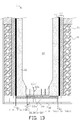
FIG. 13 is a cross sectional diagram of another example of an electric induction furnace with a lining wear detection system that includes a bottom electrically conductive mesh or wire assemblage. -
FIG. 14(a), 14(b) and 14(c) respectively illustrate in top plan view alternative bottom electrically conductive discontinuous mesh; continuous mesh; and wire assemblage, with bottom lining wear detection circuit, and control and/or indicating (detector) circuit used for bottom lining wear detection. -
FIG. 15(a) through FIG. 15(h) illustrate fabrication of alternative examples of an electric induction furnace with a lining wear detection system of the present invention that use an electrically conductive wire assemblage embedded in a wire assemblage embedded refractory. -
FIG. 16 is a detail of one example of the electrically conductive wire assemblage embedded in a refractory used in an electric induction furnace with a lining wear detection system of the present invention. -
FIG. 17 is a cross sectional diagram of another example of an electric induction furnace with a lining wear detection system of the present invention that uses an electrically conductive wire assemblage embedded in a wire assemblage embedded refractory. -
FIG. 18(a) through FIG. 18(c) illustrate alternative arrangements of electrically conductive wire assemblage, lining wear detection circuits and detectors used in the electric induction furnace with a lining wear detection system of the present invention. - Embodiments encompassing a "mesh" lining wear detection system do not form a part of the invention and represent background art that is useful for understanding the invention where a "wire" assemblage lining wear detection system is used optionally in combination with a furnace bottom mesh lining wear detection system.
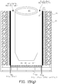
- There is shown in
FIG. 2 one example of anelectric induction furnace 10 with a lining wear detection system. A cast flowable refractory 24 is disposed betweencoil 16 andreplaceable furnace lining 12. In this example, electricallyconductive mesh 26, (for example, a stainless steel mesh) is embedded within the inner boundary of castable refractory 24 that is adjacent to the outer boundary of lining 12. One non-limiting example of a suitable mesh is formed from type 304 stainless steel welded wire cloth with mesh size 4 x 4; wire diameter between 711.2 - 812.8 µm (0.028-0.032-inch); and opening width of 5.64 - 5.54 mm (0.222-0.218-inch). As shown inFIG. 3(a) and 3(b) for this example, mesh 26 forms a discontinuous cylindrical mesh boundary between castable refractory 24 and lining 12 from the top (26TOP) to the bottom (26BOT) of the outer boundary of the lining wall. One vertical side 26a ofmesh 26 is suitably connected to a positive electric potential that can be established by a suitable voltage source, such as direct current (DC) voltage source V c that has its other terminal connected to furnace electrical ground (GND). A lining wear detection circuit is formed between the positive electric potential connected to the electrically conductive mesh and the negative electric potential connected to the furnace electrical ground. Vertical discontinuity 26c (along the height of the lining in this example) inmesh 26 is sized to prevent short circuiting between opposing vertical sides 26a and 26b ofmesh 26. Alternatively the mesh may be fabricated in a manner so that the mesh is electrically isolated from itself; for example, a layer of electrical insulation can be provided between two overlapping ends (sides 26a and 26b in this example) of the mesh. As shown inFIG. 3(a) the voltage source circuit can be connected to control and/or indicating circuits via suitable circuit elements such as a current transformer. The control and/or indicating circuits are referred to collectively as a detector. As lining 12 is gradually consumed during the service life of the furnace, DC leakage current will rise, which can be sensed in the control/indicating circuits. For a particular furnace design, a leakage current rise level set point can be established for indication of lining replacement when the furnace is properly operated and maintained. - In some examples, a bottom lining wear detection system may be provided as shown, for example in
FIG. 4 , in addition to the wall lining wear detection system shown inFIG. 2 . InFIG. 4 electrically conductivebottom mesh 30 is disposed within cast flowable refractory 28 withbottom mesh 30 adjacent to the lower boundary of lining 12 at the bottom of the furnace. As shown inFIG. 5(a) in this example,bottom mesh 30 forms a discontinuous circular mesh boundary between bottom cast flowable refractory 28 and the bottom of lining 12. In other examples, the bottom mesh boundary may be formed from a continuous circular mesh 30' as shown inFIG. 5(b) between bottom cast flowable refractory 28 and the bottom of lining 12. In the discontinuous examples, discontinuousradial side 30a ofbottom mesh 30 is suitably connected to a positive electric potential established by a suitable voltage source V'dc that has its other terminal connected to furnace electrical ground (GND). A bottom lining wear detection circuit is formed between the positive electric potential connected to the electrically conductive bottom mesh and the negative electric potential connected to the furnace electrical ground. If use,radial discontinuity 30c inmesh 30 is sized to prevent short circuiting between opposingradial sides mesh 30. Alternatively the mesh may be fabricated in a manner so that the mesh is electrically isolated from itself; for example, a layer of electrical insulation can be provided between two overlapping ends (radial sides FIG. 5(a) , the bottom lining wear detection circuit can be connected to a bottom lining wear control and/or indicating circuits, which are collectively referred to as a detector. As the bottom of lining 12 is gradually consumed during the service life of the furnace, DC leakage current will rise, which can be sensed in the bottom lining wear control and/or indicating circuits. For a particular furnace design, a leakage current rise level set point can be established for indication of lining replacement, based on bottom lining wear, when the furnace is properly operated and maintained. - The particular arrangements of the discontinuous side wall and bottom meshes shown in the figures are one example of discontinuous mesh arrangements when required in a particular application. The purpose for the discontinuity is to prevent eddy current heating of the mesh when required from inductive coupling with the magnetic flux generated when alternating current is flowing through
induction coil 16 when the coil is connected to a suitable alternating current power source during operation of the furnace. Therefore other arrangements of side wall and bottom meshes are acceptable as long as the mesh arrangement prevents such inductive heating of the mesh when required in a particular application. Similarly arrangement of the electrical connection(s) of the mesh to the lining wear detection circuit, and the control and/or indicating circuits can vary depending upon a particular furnace design. Depending upon the physical arrangement of a particular electric induction furnace continuous bottom and/or side wall meshes may be satisfactory without excessive eddy current heating. - In some examples refractory embedded
wall mesh 26 may extend for the entire vertical height of lining 12, that is, from the bottom (12BOT) of the furnace lining to the very top (12TOP) of the furnace lining that is above the nominaldesign melt line 25 for a particular furnace as shown, for example, inFIG. 8 . - In other applications,
wall mesh 26 may be provided in one or more selected discrete regions along the vertical height of lining 12. For example inFIG. 9(a) and FIG. 9(b) wall mesh comprises two vertical electricallyconductive meshes vertical sides vertical sides meshes FIG. 9(c) the multiple electricallyconductive meshes 46a through 46d can be horizontally oriented with each electrically isolated mesh connected to a separate lining wear detection circuit and control and/or indicating circuits (D) so that lining wear can be localized to one of the isolated mesh regions. Most generally as shown inFIG. 9(d) the multiple electrically conductive meshes 56a through 56p can be arrayed around the height of the replaceable lining wall with each electrically conductive mesh connected to a separate lining wear detection circuit, and control and/or indicating circuits (not shown in the figure) so that lining wear can be localized to one of the isolated mesh regions that can be defined by a two-dimensional X-Y coordinate system around the circumference of the replaceable lining wall with the X coordinate defining a position around the circumference of the lining and the Y coordinate defining a position along the height of the lining. - In similar
fashion bottom mesh 30 may cover less than the entire bottom ofreplaceable lining 12 in some examples, or comprise a number of electrically isolated bottom meshes with each of the electrically isolated bottom meshes connected to a separate lining wear detection circuit so that lining wear could be localized to one of the bottom mesh regions. - Alternatively to a separate detector (control and/or indicating circuits) used with each lining wear detection circuit in the above examples, a single detector can be switchably connected to the lining wear detection circuits associated with two or more of the electrically isolated meshes.
- While the figures illustrate separate wall and bottom lining wear detection systems, in some examples, a combined wall and bottom lining wear detection system may be provided either by (1) providing a continuous side and bottom mesh embedded in an integrally cast flowable refractory with a single lining wear detection circuit and detector or (2) providing separate side and bottom meshes embedded in a cast flowable refractory with a common lining wear detection circuit and detector.
-
FIG. 6(a) through FIG. 6(f) illustrate one example of fabrication of an electric induction furnace with a lining wear detection system.Induction coil 16 can be fabricated (typically wound) and positioned oversuitable foundation 18. As shown inFIG. 6(a) trowelable refractory (grout)material 20, or other refractory, can be installed around the coil as in the prior art. One suitable proprietary trowelablerefractory material 20 is INDUCTOCOAT™ 35AF (available from Inductotherm Corp., Rancocas, New Jersey). If a bottom lining wear detection system is used,bottom mesh 30 can be fitted at the top offoundation 18 and embedded in cast flowable refractory by pouring the cast flowable refractory aroundbottom mesh 30 so that the mesh is embedded within the refractory after it sets as shown inFIG. 6(b) . Alternatively the bottom mesh can be cast in a cast flowable refractory 28 in a separate mold and then the cast refractory embedded bottom mesh can be installed in the bottom of the furnace after the cast flowable refractory sets. - A suitable temporary cast flowable refractory mold 90 (or molds forming a formwork) for example, in the shape of an open right cylinder, is positioned within the volume formed by
coil 16 andrefractory material 20 to form a cast flowable refractory annular volume betweenrefractory material 20 and the outer wall perimeter of the mold as shown inFIG. 6(c) .Mesh 26 is fitted around the outer perimeter oftemporary mold 90 and the cast flowable refractory 24, such as INDUCTOCOAT™ 35AF-FLOW (available from Inductotherm Corp., Rancocas, New Jersey), can be poured into the cast flowable refractory annular volume to set and form hardened castable refractory 24 as shown inFIG. 6(e) . Vibrating compactors can be used to release trapped air and excess water from the cast flowable refractory so that the refractory settles firmly in place in the formwork before setting.Mesh 26 will be at least partially embedded in cast flowable refractory 24 when it sets inside of the cast flowable refractory annular volume. In other examples mesh 26 can be embedded anywhere within the thickness, t, of cast flowable refractory 24. For example as shown inFIG. 7 ,mesh 26 is offset by distance, t1, from the inner wall perimeter of cast flowable refractory 24. Offset embedment can be achieved by installingsuitable standoffs 91 around the outer perimeter ofmold 90 as shown inFIG. 6(d) and then fittingmesh 26 around the standoffs before pouring the cast flowable refractory. In the broadest sense as used herein, the terminology mesh "embedded" in a cast flowable refractory is understood as the mesh is either fixed within the refractory; at a surface boundary of the refractory, or sufficiently, but not completely, embedded at a surface boundary of the refractory so that the mesh is retained in place in the refractory after the refractory sets. - After cast flowable refractory 24 sets,
temporary mold 90 is removed, and areplaceable lining mold 92 that is shaped to conform to the boundary wall and bottom ofinterior furnace volume 14 can be positioned within the volume formed by set cast flowable refractory 24 (with embedded mesh 26) to form a replaceable lining annular volume between set cast flowable refractory 24 and the outer wall perimeter of the liningmold 92 as shown inFIG. 6(f) . A conventional powdered refractory can then be fed into the lining volume according to conventional procedures. If liningmold 92 is formed from an electrically conductive mold material, liningmold 92 can be heated and melted in place according to conventional procedures to sinter the lining refractory layer that forms the boundary offurnace volume 14. Alternatively the lining mold may be removed and sintering of the lining refractory layer may be accomplished by direct heat application. - Distinction is made between the replaceable lining refractory, which is typically a powdered refractory and the cast flowable refractory in which the electrically conductive mesh is embedded. The cast flowable refractory is preferably used so that the electrically conductive mesh can be embedded in the refractory. The cast flowable refractory is also referred to herein as castable refractory and flowable refractory.
-
FIG. 6(g) illustrates an electric induction furnace with one example of a lining wear detection system with addition of typical furnace ground leak detectorsystem probe wires 22a andelectrical ground lead 22b that is connected to a furnace electrical ground (GND). - The fabrication process described above and as shown in
FIG. 6(a) through FIG. 6(g) illustrates one example of fabrication steps of an electric induction furnace with a lining wear detection system. Additional conventional fabrication steps may be required to complete furnace construction. - There is shown in
FIG. 10 one example of anelectric induction furnace 11 with a lining wear detection system. A wall refractory 23 is disposed betweencoil 16 and replaceable furnace lining 12 and is also referred to as wire assemblage refractory 23. The wall refractory may be a castable or trowelable refractory. In this example of the invention, electricallyconductive wire assemblage 27 is embedded within the inner boundary of wall refractory 23 that is adjacent to the outer boundary of lining 12, and wall refractory 23 is also referred to as the wire assemblage refractory. One non-limiting example of a suitable electrically conductive wire assemblage is formed from an assemblage of stainless or copper nickel stranded wire in a range from 18 to 10 AWG depending upon the particular configuration of the induction furnace. In other arrangements of the invention other types of electrically conductive wire may be used as suitable for a particular application. The wire may be bare or insulated if arcing is an issue in a particular application. Stranded wire is preferred although solid wire may be used in some applications. As shown inFIG. 11(a) and 11(b) , for this example of the invention, electricallyconductive wire assemblage 27 forms a vertical wire cage between wire assemblage refractory 23 and consumable lining 12 from the top (26TOP) to the bottom (26BOT) of the outer boundary of the replaceable lining wall to separate thereplaceable lining wall 12 frominduction coil 16. In this example of the invention twenty-sixvertical wires 271 to 2726 are vertically spaced apart from each other around the circumference of wire assemblage refractory 23. In this example of the invention the twenty-six vertically oriented wires are electrically connected together by suitable electrically connecting means such as acollector wire 29 formed from multiple tap connecters or wire lugs 31 to a bottom collector wire of electricallyconductive wire assemblage 27 in this example of the invention. - More generally the number of vertical wires used depends upon the configuration of a particular induction furnace and are referred to as riser protection wires. While vertically-oriented riser protection wires are shown in the above example of the invention, in other examples the arrangement of riser protection wires around the circumference of wire assemblage refractory 23 may be of other configurations such as a spiral configuration. While a bottom collector wire is used in the above example of the invention the collector wire may be located anywhere between the top and bottom ends of the riser protection wires and there may be more than one collector wire depending upon a particular application.
- In the above example of the invention,
collector wire 29 is connected at a single terminal point T1 to a positive electric potential that can be established by a suitable voltage source, such as direct current (DC) voltage source Vdc that has its other (negative) terminal connected to furnace electrical ground (GND). A lining wear detection circuit is formed between the positive electric potential connected to electricallyconductive wire assemblage 27 and the negative electric potential connected to the furnace electrical ground. As shown inFIG. 11(a) the voltage source circuit can be connected to control circuits and/or indicating circuits via suitable circuit elements such as a current transformer. Alternatively a direct measurement of leakage current can be provided with suitable direct measurement device such as, but not limited to, a current shunt resistor. The control and/or indicating circuits are referred to collectively as a detector. Asconsumable lining 12 is gradually consumed during the service life of the furnace, DC leakage current will rise, which can be sensed in the control/indicating circuits. For a particular furnace design, a leakage current rise level set point can be established for indication of lining replacement when the furnace is properly operated and maintained. -
FIG. 12(a) illustrates an alternative to the protective riser wires shown inFIG. 11(a) . InFIG. 12(a) a singlecontinuous riser wire 35, which is also referred to as aprotective riser wire 35, is provided by weaving the riser wire around the top and bottom circumferences of the induction furnace. Top wire assemblage fixture (fitting) 51 as shown inFIG. 12(b) and FIG. 12(c) is used to facilitate weaving the singlecontinuous wire 35.Fixture 51 is generally cylindrical in shape and has top wire turn notches 51' that facilitate turn of thecontinuous riser wire 35 at the top of the furnace during installation. Each wire turn notch 51' comprises a generally semicircular cutout volume as seen in cross section inFIG. 12(c) and FIG 12(d) that is larger in cross section than the cross sectional diameter ofcontinuous riser wire 35 to allow rapid insert of the wire into thewire seating sub-notch 51" at the bottom of each wire turn notch 51'. Eachwire seating sub-notch 51" has a cross sectional diameter slightly larger than the cross sectional diameter ofwire 35. Off-centering ofwire seating sub-notch 51" in the direction of the top-to-bottom weave (illustrated by the arrow inFIG. 12(c) ) assists in making the turn of the riser wire 180 degrees from the upward to downward direction at the top of the furnace. A bottom wire assemblage fixture (fitting) 52 as shown inFIG. 12(e) is provided to facilitate weaving of thecontinuous riser wire 35 at the bottom of the induction furnace being assembled.Bottom fixture 52 is similar totop fixture 51 rotated 180 degrees as shown in the figures with complementary arranged bottom wire turn notches 52' andwire seating sub-notches 52". The top and bottom fixtures are temporarily positioned respectively at, or adjacent to, the top and bottom of the wire assemblage refractory when used during the fabrication of an electric induction furnace. - In some examples, a bottom lining wear detection system may be provided as alternatively shown, for example in
FIG. 14(a), 14(b) or 14(c) , in addition to one of the wall lining wear detection systems shown inFIG. 11(a) and FIG. 11(b) . InFIG. 13 electrically conductive discontinuousbottom mesh 30; continuous bottom mesh 30'; orwire assemblage 30" is disposed within bottom refractory 28 withbottom mesh 30 adjacent to the lower boundary of lining 12 at the bottom of the furnace. For the bottom lining wear system shown inFIG. 14(a) ,bottom mesh 30 forms an electrically discontinuous circular mesh boundary between bottom refractory 28 and the bottom of lining 12. In alternative applications, the bottom mesh boundary may be formed from a continuous circular mesh 30' as shown inFIG. 14(b) between bottom cast flowable refractory 28 and the bottom of lining 12, or one or more electricallyconductive wire assemblage 30" as shown inFIG. 14(c) with a plurality of electrically isolated bottomlinear wires 30"a interconnected bybottom collector wire 30"b. In examples where the electrically discontinuousbottom mesh 30 is used, at least one discontinuousradial side 30a ofbottom mesh 30 is suitably connected to a positive electric potential established by a suitable voltage source V'dc that has its other terminal connected to furnace electrical ground (GND). A bottom lining wear detection circuit is formed between the positive electric potential connected to the electrically conductive bottom mesh or wire assemblage and the negative electric potential connected to the furnace electrical ground. In applications where it is used, the at least one radialelectrical discontinuity 30c inmesh 30 is sized to prevent short circuiting between opposingradial sides mesh 30 and may includemultiple discontinuities FIG. 14(a) when required for a particular application. In alternative applications, the bottom mesh boundary may be formed from a continuous circular mesh 30' as shown inFIG. 14(b) between bottom cast flowable refractory 28 and the bottom of lining 12, or one or more electricallyconductive wire assemblage 30" as shown inFIG. 14(c) . Alternatively the mesh may be fabricated in a manner so that the mesh is electrically isolated from itself. As shown in the alternative arrangements ofFIG. 14(a), FIG. 14(b) and FIG. 14(c) , the bottom lining wear detection circuit can be connected to a bottom lining wear control and/or indicating circuits, which are collectively referred to as a detector. As the bottom of lining 12 is gradually consumed during the service life of the furnace, DC leakage current will rise, which can be sensed in the bottom lining wear control and/or indicating circuits. For a particular furnace design, a leakage current rise level set point can be established for indication of lining replacement, based on bottom lining wear, when the furnace is properly operated and maintained. - In some examples of the invention, electrically
conductive wire assemblage design melt line 25 for a particular furnace as shown, for example, inFIG. 17 for electricallyconductive wire assemblage 27. - In other applications, electrically
conductive wire assemblage 27 may be provided in one or more selected discrete regions along the vertical height of lining 12. For example inFIG. 18(a) the electrically conductive wire assemblage comprises two vertical electricallyconductive wire assemblages conductive wire assemblages FIG. 18(a) can be horizontally oriented with each electrically isolated electrically conductive wire assemblage connected to a separate lining wear detection circuit and control and/or indicating circuits (D) so that lining wear can be localized to one of the isolated wire assemblage regions. One or more of the vertical risers may be oriented in different directions. Forexample wire assemblage 55a at the top of the furnace inFIG. 18(b) has the protection wires oriented with horizontal whilewire assemblages FIG. 18(c) the multiple electrically conductive wire assemblage 59a through 59p can be arrayed around the height of the replaceable lining wall with each electrically conductive wire assemblage connected to a separate lining wear detection circuit (D) with control and/or indicating circuit so that lining wear can be localized to one of the isolated electrically conductive wire assemblage regions that can be defined by a two-dimensional X-Y coordinate system around the circumference of the replaceable lining wall with the X (horizontal) coordinate defining a position around the circumference of the lining and the Y (vertical) coordinate defining a position along the height of the lining. - In similar fashion bottom,
discontinuous mesh 30, continuous mesh 30' orwire assemblage 30" may cover less than the entire bottom ofreplaceable lining 12 in some examples , or comprise a number of electrically isolated bottom meshes or wire assemblages with each of the electrically isolated bottom meshes or wire assemblages connected to a separate lining wear detection circuit so that lining wear could be localized to one of the bottom mesh or wire assemblage regions. - As an alternative to a separate detector (control and/or indicating circuits) for each lining wear detection circuit in the above examples, a single detector can be switchably connected to the lining wear detection circuits associated with two or more of the electrically conductive meshes or wire assemblages in all examples.
- While the figures illustrate separate wall electrically conductive wire assemblage and bottom lining wear detection systems, in some examples, a combined wall electrically conductive wire assemblage and bottom lining wear detection system may be provided either by (1) providing a continuous side electrically conductive wire assemblage and bottom mesh or wire assemblage embedded in a refractory with a single lining wear detection circuit and detector or (2) providing separate side electrically conductive wire assemblage and bottom meshes or wire assemblages embedded in a refractory with a common lining wear detection circuit and detector.
-
FIG. 15(a) through FIG. 15(h) illustrate examples of the fabrication of an electric induction furnace with a lining wear detection system of the present invention with a side electrically conductive wire assemblage.Induction coil 16 can be fabricated (typically wound) and positioned oversuitable foundation 18. As shown inFIG. 15(a) trowelable refractory (grout)material 20, or other suitable refractory, can be installed around the coil as in the prior art. One suitable proprietary trowelablerefractory material 20 is INDUCTOCOAT™ 35AF (available from Inductotherm Corp., Rancocas, New Jersey). If a bottom lining wear detection system is used, an alternative discontinuous or continuousbottom mesh 30 or 30', orwire assemblage 30" can be fitted at the top offoundation 18 and embedded in a bottom refractory, for example, a cast flowable refractory by pouring the cast flowable refractory around the selected bottom mesh or wire assemblage so that the mesh or wire assemblage is embedded within the refractory after it sets as shown inFIG. 15(b) . Alternatively the bottom mesh or wire assemblage can be cast in refractory 28 in a separate mold and then the cast refractory embedded bottom mesh or wire assemblage can be installed in the bottom of the furnace after the cast flowable refractory sets. - A suitable temporary cast flowable refractory mold 90 (or molds forming a formwork) for example, in the shape of an open right cylinder, is positioned within the volume formed by
coil 16 andrefractory material 20 to form a wire assemblage refractory annular volume betweenrefractory material 20 and the outer wall perimeter of the mold as shown inFIG. 15(c) .Mold 90 is also referred to as the wire assemblage refractory mold. Electricallyconductive wire assemblage 27, for example as shown inFIG. 11(a) , is fitted around the outer perimeter oftemporary mold 90 and the wire assemblage refractory 23, such as INDUCTOCOAT™ 35AF-FLOW (available from Inductotherm Corp., Rancocas, New Jersey), can be supplied to the wire assemblage refractory annular volume to set and form hardened wire assemblage refractory 23 as shown inFIG. 15(f) . - Alternatively for the electrically
conductive wire assemblage 35 shown inFIG. 12(a) temporary top wire assemblage fixture (or fitting) 51 is positioned at the top, or adjacent to the top, oftemporary mold 90 inFIG. 15(d) . A temporary bottom wire assemblage fixture (or fitting) 52 is positioned at the bottom, or adjacent to the bottom, oftemporary mold 90 and continuous electricallyconductive wire 35 is weaved vertically around the outer circumference of the temporary mold in this example of the invention by using the top and bottom fittings as further illustrated inFIG. 12(d) which temporary fittings are removed afterwire 35 is weaved. Onecontinuous wire 35 may be weaved around the entire circumference of the temporary mold or two or more continuous wires may be used to complete a weave around the entire circumference. - An alternative method of forming the electrically
conductive wire assemblage 27 inFIG. 11(a) is to weave continuous electricallyconductive wire 35 shown inFIG. 12(a) vertically around the outer circumference oftemporary mold 90 as described in the previous paragraph and then cut off all the top loops 35a andbottom loops 35b shown inFIG. 12(a) of the continuous electrically conductive wire to form theriser wires 271 to 2726 inFIG. 11(a) ; the riser wires are then connected together, for example, at the bottom of the induction furnace with acollector wire 29 to form the electricallyconductive wire assemblage 27 shown inFIG. 11(a) . - Vibrating compactors can be used to release trapped air and excess water from a cast flowable refractory (if used) so that the wire assemblage refractory settles firmly in place in the formwork before setting. Electrically
conductive wire assemblage - In other examples of the invention electrically
conductive wire assemblage FIG. 16 , electricallyconductive wire assemblage 27 is offset by distance, t1, from the inner wall perimeter of wire assemblage refractory 23. Offset embedment can be achieved by installingsuitable standoffs 91 around the outer perimeter ofmold 90 as shown inFIG. 15(e) and then fitting electricallyconductive wire assemblage 27 around the standoffs before providing the wire assemblage refractory. In the broadest sense as used herein, the terminology mesh or wire assemblage "embedded" in a refractory is used to indicate that the mesh or wire assemblage is either fixed within the refractory; at a surface boundary of the refractory, or sufficiently, but not completely, embedded at a surface boundary of the refractory so that the mesh or wire assemblage is retained in place in the refractory after the refractory sets. - After wire assemblage refractory 23 sets,
temporary mold 90 is removed (with top 51 and bottom 52 wire assemblage fixtures if used), and areplaceable lining mold 92 that is shaped to conform to the boundary wall and bottom ofinterior furnace volume 14 can be positioned within the volume formed by set wire assemblage refractory 23 (with embedded wire assemblage 27) to form a replaceable lining annular volume between set cast flowable refractory 23 and the outer wall perimeter of the liningmold 92 as shown inFIG. 15(g) . A conventional powdered refractory, for example, can then be fed into the lining volume according to conventional procedures. If liningmold 92 is formed from an electrically conductive mold material, liningmold 92 can be heated and melted in place according to conventional procedures to sinter the lining refractory layer that forms the boundary offurnace volume 14. Alternatively the lining mold may be removed and sintering of the lining refractory layer may be accomplished by direct heat application. - Distinction is made between the replaceable lining refractory, which is typically a powdered refractory and the cast flowable refractory in which the electrically conductive mesh or wire assemblage is typically embedded. The cast flowable refractory is preferably used so that the electrically conductive mesh or wire assemblage can be embedded in the refractory. The cast flowable refractory is also referred to herein as castable refractory and flowable refractory.
-
FIG. 15(h) illustrates an electric induction furnace with one example of a lining wear detection system of the present invention withside wire assemblage 27 addition of typical furnace ground leak detectorsystem probe wires 22a andelectrical ground lead 22b that is connected to a furnace electrical ground (GND). - The fabrication processes described above and as shown in
FIG. 15(a) through FIG. 15(h) illustrate non-limiting examples of fabrication steps exemplary to the present invention. Additional conventional fabrication steps may be required to complete furnace construction. - In alternative examples of the invention rather than using a separate trowelable refractory (grout) around
coil 16, cast flowable refractory 24 can be extended to, and aroundcoil 16. - The induction furnace of the present invention may be of any type, for example, a bottom pour, top tilt pour, pressure pour, or push-out electric induction furnace, operating at atmosphere or in a controlled environment such as an inert gas or vacuum. While the induction furnace shown in the figures has a circular interior cross section, furnaces with other cross sectional shapes, such as square, may also utilize the present invention. While a single induction coil is shown in the drawing for the electric induction furnace of the present invention, the term "induction coil" as used herein also includes a plurality of induction coils either with individual electrical connections and/or electrically interconnected induction coils.
- Further the lining wear detection system of the present invention may also be utilized in portable refractory lined ladles used to transfer molten metals between locations and stationary refractory lined launders.
- The examples of the invention include reference to specific electrical components. One skilled in the art may practice the invention by substituting components that are not necessarily of the same type but will create the desired conditions or accomplish the desired results of the invention. For example, single components may be substituted for multiple components or vice versa.
Claims (8)
- A method of fabricating an electric induction furnace (11) with a lining wear detection system, the method comprising the steps of:locating a wound induction coil (16) above a foundation (18);installing a refractory (20) around the wound induction coil (16) to form a refractory embedded induction coil;positioning a wire assemblage refractory mold (90) within the refractory embedded induction coil to provide a wire assemblage refractory volume between an outer wire assemblage refractory mold wall of the wire assemblage refractory mold (90) and an inner refractory embedded induction coil wall of the refractory embedded induction coil;fitting a temporary top wire assemblage fixture (51) around the top circumference of the wire assemblage refractory mold (90) and a temporary bottom wire assemblage fixture (52) around the bottom circumference of the wire assemblage refractory mold, each of the temporary top and bottom wire assemblage fixtures having a plurality of circumferential wire insertion notches (51', 52') around the circumference of each of the temporary top and bottom wire assemblage fixtures (51, 52), each of the plurality of circumferential wire insertion notches having a wire turn sub-notch (51", 52");fitting at least one electrically conductive wire assemblage (27) around the outer wire assemblage refractory mold wall of the wire assemblage refractory mold (90), the at least one electrically conductive wire assemblage (27) comprising at least one continuous wire, the at least one continuous wire (35) vertically weaved at least partially around the height of the outer circumference of the temporary top and bottom wire assemblage fixtures (51, 52) by sequential insertion of the single continuous wire (35) within the wire turn sub-notch (51", 52") of each circumferential wire insertion notches (51', 52') of the temporary top and bottom wire assemblage fixtures;providing a wire assemblage refractory (23) into the wire assemblage refractory volume to embed the at least one electrically conductive wire assemblage (27) in the wire assemblage refractory (23) to form an embedded wire assemblage refractory in the wire assemblage refractory volume;removing the wire assemblage refractory mold (90) and the temporary top and bottom wire assemblage fixtures (51, 52) to form an interior wire assemblage refractory furnace volume;positioning a replaceable lining mold (92) within the interior of the wire assemblage refractory furnace volume to form a replaceable lining wall volume between an outer replaceable lining mold wall of the replaceable lining mold (92) and an inner embedded wire assemblage refractory wall of the embedded wire assemblage refractory, and a replaceable lining bottom volume above the foundation (18);feeding a replaceable lining refractory (12) into the replaceable lining wall volume and the replaceable lining bottom volume; andremoving the replaceable lining mold (92) to form an interior volume of the electric induction furnace (11).
- The method of claim 1 wherein the at least one continuous wire (35) comprises a single electrically continuous wire weaved around the circumference of the wire assemblage refractory mold (90).
- The method of claim 2 further comprising cutting off the top (35a) and the bottom (35b) loops of the single electrically continuous wire (35) to form a plurality of vertically oriented wires spaced apart horizontally from each other around the outer circumference of the replaceable lining (23) within the wire assemblage refractory (27) and electrically joining the plurality of vertically oriented wires with a collector wire (29).
- The method of claim 1, 2 or 3 further comprising the step of fitting at least one bottom continuous (30') or discontinuous (30) electrically conductive mesh or at least one bottom electrically conductive wire assemblage (30") embedded in a bottom refractory above the foundation (18) and below the replaceable lining bottom volume.
- The method of claim 1 to 3 further comprising the step of installing a lining wear detection circuit from each of the at least one continuous wires to a furnace electrical ground (GND) connection.
- The method of claim 5 further comprising the step of installing at least one detector for the lining wear detection circuit.
- The method of claim 4 further comprising the step of installing a bottom lining wear detection circuit from each of the at least one bottom continuous (30') or discontinuous (30) electrically conductive mesh or the at least one bottom electrically conductive wire assemblage (30") to a furnace electrical ground (GND) connection.
- The method of claim 7 further comprising the step of installing at least one detector for the bottom lining wear detection circuit.
Applications Claiming Priority (2)
| Application Number | Priority Date | Filing Date | Title |
|---|---|---|---|
| US15/218,787 US10598439B2 (en) | 2011-05-23 | 2016-07-25 | Electric induction furnace lining wear detection system |
| PCT/US2017/043429 WO2018022472A1 (en) | 2016-07-25 | 2017-07-23 | Electric induction furnace with lining wear detection system |
Publications (3)
| Publication Number | Publication Date |
|---|---|
| EP3488167A1 EP3488167A1 (en) | 2019-05-29 |
| EP3488167A4 EP3488167A4 (en) | 2020-01-08 |
| EP3488167B1 true EP3488167B1 (en) | 2020-11-25 |
Family
ID=61017521
Family Applications (1)
| Application Number | Title | Priority Date | Filing Date |
|---|---|---|---|
| EP17835034.4A Active EP3488167B1 (en) | 2016-07-25 | 2017-07-23 | Electric induction furnace with lining wear detection system |
Country Status (10)
| Country | Link |
|---|---|
| EP (1) | EP3488167B1 (en) |
| JP (1) | JP7014767B2 (en) |
| KR (1) | KR102429227B1 (en) |
| CN (1) | CN109791021B (en) |
| AU (1) | AU2017301416B2 (en) |
| BR (1) | BR112019001109B1 (en) |
| CA (1) | CA3029847A1 (en) |
| MX (1) | MX2019001029A (en) |
| RU (1) | RU2019104712A (en) |
| WO (1) | WO2018022472A1 (en) |
Family Cites Families (15)
| Publication number | Priority date | Publication date | Assignee | Title |
|---|---|---|---|---|
| US1922029A (en) * | 1931-07-22 | 1933-08-15 | Ajax Electrothermic Corp | Protective device for induction furnace |
| JPS5387038A (en) * | 1977-01-12 | 1978-08-01 | Toshiba Corp | Induction melting furnace |
| JPS58131398U (en) * | 1982-02-27 | 1983-09-05 | 北芝電機株式会社 | Induction melting furnace leak detection device |
| GB8409063D0 (en) * | 1984-04-07 | 1984-05-16 | Foseco Trading Ag | Furnaces |
| JPS60176100U (en) * | 1984-04-27 | 1985-11-21 | 神鋼電機株式会社 | Hot water leak detection device in induction furnace |
| JPH01153498U (en) * | 1988-04-13 | 1989-10-23 | ||
| DE4120205A1 (en) * | 1991-06-19 | 1992-12-24 | Saveway Gmbh | WARNING DEVICE FOR INDUCTION MELTING OVENS |
| DE4322463A1 (en) * | 1993-07-06 | 1995-01-12 | Leybold Durferrit Gmbh | Early-warning device for induction melting furnaces |
| DE19602249A1 (en) * | 1996-01-23 | 1997-07-24 | Ald Vacuum Techn Gmbh | Early warning system for molten metal break-through in induction furnaces |
| US6148018A (en) * | 1997-10-29 | 2000-11-14 | Ajax Magnethermic Corporation | Heat flow sensing system for an induction furnace |
| US7097051B2 (en) * | 2003-08-15 | 2006-08-29 | Maytag Corporation | Hanger rod for drying cabinet |
| DE102006006524B4 (en) * | 2006-02-10 | 2008-11-27 | Saveway Gmbh & Co. Kg | Method for monitoring an induction furnace and induction furnace |
| JP5085181B2 (en) * | 2007-04-26 | 2012-11-28 | 新日本製鐵株式会社 | Refractory thickness detection method and refractory deterioration judgment method |
| CA2837074A1 (en) * | 2011-05-23 | 2012-11-29 | Inductotherm Corp. | Electric induction furnace with lining wear detection system |
| DE102013002797B4 (en) * | 2012-11-09 | 2015-06-25 | Abp Induction Systems Gmbh | Method and device for automatically detecting the integrity of earthing electrodes in the bath of an induction furnace and induction furnace |
-
2017
- 2017-07-23 EP EP17835034.4A patent/EP3488167B1/en active Active
- 2017-07-23 BR BR112019001109-9A patent/BR112019001109B1/en active IP Right Grant
- 2017-07-23 RU RU2019104712A patent/RU2019104712A/en not_active Application Discontinuation
- 2017-07-23 AU AU2017301416A patent/AU2017301416B2/en active Active
- 2017-07-23 WO PCT/US2017/043429 patent/WO2018022472A1/en not_active Ceased
- 2017-07-23 JP JP2019502089A patent/JP7014767B2/en active Active
- 2017-07-23 MX MX2019001029A patent/MX2019001029A/en unknown
- 2017-07-23 CN CN201780057894.XA patent/CN109791021B/en active Active
- 2017-07-23 KR KR1020197005506A patent/KR102429227B1/en active Active
- 2017-07-23 CA CA3029847A patent/CA3029847A1/en not_active Abandoned
Non-Patent Citations (1)
| Title |
|---|
| None * |
Also Published As
| Publication number | Publication date |
|---|---|
| AU2017301416A1 (en) | 2019-02-14 |
| CN109791021A (en) | 2019-05-21 |
| RU2019104712A (en) | 2020-08-25 |
| BR112019001109B1 (en) | 2022-09-27 |
| MX2019001029A (en) | 2019-04-25 |
| CN109791021B (en) | 2021-03-19 |
| JP2019526027A (en) | 2019-09-12 |
| EP3488167A4 (en) | 2020-01-08 |
| AU2017301416B2 (en) | 2023-02-02 |
| KR102429227B1 (en) | 2022-08-04 |
| BR112019001109A2 (en) | 2019-04-30 |
| JP7014767B2 (en) | 2022-02-01 |
| KR20190025736A (en) | 2019-03-11 |
| EP3488167A1 (en) | 2019-05-29 |
| WO2018022472A1 (en) | 2018-02-01 |
| CA3029847A1 (en) | 2018-02-01 |
Similar Documents
| Publication | Publication Date | Title |
|---|---|---|
| EP2715262B1 (en) | Electric induction furnace with lining wear detection system | |
| JP2014522474A5 (en) | ||
| US6148018A (en) | Heat flow sensing system for an induction furnace | |
| CZ285114B6 (en) | Preliminary alarm device for melting furnaces | |
| US12098886B2 (en) | Electric induction furnace with lining wear detection system | |
| AU2017301416B2 (en) | Electric induction furnace with lining wear detection system | |
| JP2010025464A (en) | Unit for measuring molten material surface level in vertical type furnace and measuring method therefor | |
| EP0990109B1 (en) | Channel inductor | |
| JPS59185713A (en) | Method and device for measuring eroded region in bottom refractories of blast furnace | |
| JPS6126858Y2 (en) | ||
| JPH06313681A (en) | Method and apparatus for detecting degree of wear of refractory lining in induction furnace etc. | |
| JPH09303971A (en) | Leakage detector for induction melting furnace | |
| JP4232406B2 (en) | Melting leak detection method for melting holding furnace and melting holding furnace | |
| JPH0350400Y2 (en) | ||
| JP6051000B2 (en) | Sleeve heating device | |
| JP5005357B2 (en) | Molten metal leak detecting device for molten metal holding furnace and molten metal leak detecting method using the same |
Legal Events
| Date | Code | Title | Description |
|---|---|---|---|
| STAA | Information on the status of an ep patent application or granted ep patent |
Free format text: STATUS: THE INTERNATIONAL PUBLICATION HAS BEEN MADE |
|
| PUAI | Public reference made under article 153(3) epc to a published international application that has entered the european phase |
Free format text: ORIGINAL CODE: 0009012 |
|
| STAA | Information on the status of an ep patent application or granted ep patent |
Free format text: STATUS: REQUEST FOR EXAMINATION WAS MADE |
|
| 17P | Request for examination filed |
Effective date: 20190123 |
|
| AK | Designated contracting states |
Kind code of ref document: A1 Designated state(s): AL AT BE BG CH CY CZ DE DK EE ES FI FR GB GR HR HU IE IS IT LI LT LU LV MC MK MT NL NO PL PT RO RS SE SI SK SM TR |
|
| AX | Request for extension of the european patent |
Extension state: BA ME |
|
| DAV | Request for validation of the european patent (deleted) | ||
| DAX | Request for extension of the european patent (deleted) | ||
| A4 | Supplementary search report drawn up and despatched |
Effective date: 20191205 |
|
| RIC1 | Information provided on ipc code assigned before grant |
Ipc: H05B 6/06 20060101ALI20191130BHEP Ipc: F27D 11/06 20060101ALI20191130BHEP Ipc: H05B 6/28 20060101ALI20191130BHEP Ipc: F27D 21/00 20060101AFI20191130BHEP |
|
| GRAP | Despatch of communication of intention to grant a patent |
Free format text: ORIGINAL CODE: EPIDOSNIGR1 |
|
| STAA | Information on the status of an ep patent application or granted ep patent |
Free format text: STATUS: GRANT OF PATENT IS INTENDED |
|
| INTG | Intention to grant announced |
Effective date: 20200827 |
|
| GRAS | Grant fee paid |
Free format text: ORIGINAL CODE: EPIDOSNIGR3 |
|
| GRAA | (expected) grant |
Free format text: ORIGINAL CODE: 0009210 |
|
| STAA | Information on the status of an ep patent application or granted ep patent |
Free format text: STATUS: THE PATENT HAS BEEN GRANTED |
|
| AK | Designated contracting states |
Kind code of ref document: B1 Designated state(s): AL AT BE BG CH CY CZ DE DK EE ES FI FR GB GR HR HU IE IS IT LI LT LU LV MC MK MT NL NO PL PT RO RS SE SI SK SM TR |
|
| REG | Reference to a national code |
Ref country code: GB Ref legal event code: FG4D |
|
| REG | Reference to a national code |
Ref country code: CH Ref legal event code: EP |
|
| REG | Reference to a national code |
Ref country code: AT Ref legal event code: REF Ref document number: 1338815 Country of ref document: AT Kind code of ref document: T Effective date: 20201215 |
|
| REG | Reference to a national code |
Ref country code: DE Ref legal event code: R096 Ref document number: 602017028526 Country of ref document: DE |
|
| REG | Reference to a national code |
Ref country code: IE Ref legal event code: FG4D |
|
| REG | Reference to a national code |
Ref country code: AT Ref legal event code: MK05 Ref document number: 1338815 Country of ref document: AT Kind code of ref document: T Effective date: 20201125 |
|
| REG | Reference to a national code |
Ref country code: NL Ref legal event code: MP Effective date: 20201125 |
|
| PG25 | Lapsed in a contracting state [announced via postgrant information from national office to epo] |
Ref country code: NO Free format text: LAPSE BECAUSE OF FAILURE TO SUBMIT A TRANSLATION OF THE DESCRIPTION OR TO PAY THE FEE WITHIN THE PRESCRIBED TIME-LIMIT Effective date: 20210225 Ref country code: GR Free format text: LAPSE BECAUSE OF FAILURE TO SUBMIT A TRANSLATION OF THE DESCRIPTION OR TO PAY THE FEE WITHIN THE PRESCRIBED TIME-LIMIT Effective date: 20210226 Ref country code: PT Free format text: LAPSE BECAUSE OF FAILURE TO SUBMIT A TRANSLATION OF THE DESCRIPTION OR TO PAY THE FEE WITHIN THE PRESCRIBED TIME-LIMIT Effective date: 20210325 Ref country code: RS Free format text: LAPSE BECAUSE OF FAILURE TO SUBMIT A TRANSLATION OF THE DESCRIPTION OR TO PAY THE FEE WITHIN THE PRESCRIBED TIME-LIMIT Effective date: 20201125 Ref country code: FI Free format text: LAPSE BECAUSE OF FAILURE TO SUBMIT A TRANSLATION OF THE DESCRIPTION OR TO PAY THE FEE WITHIN THE PRESCRIBED TIME-LIMIT Effective date: 20201125 |
|
| PG25 | Lapsed in a contracting state [announced via postgrant information from national office to epo] |
Ref country code: LV Free format text: LAPSE BECAUSE OF FAILURE TO SUBMIT A TRANSLATION OF THE DESCRIPTION OR TO PAY THE FEE WITHIN THE PRESCRIBED TIME-LIMIT Effective date: 20201125 Ref country code: PL Free format text: LAPSE BECAUSE OF FAILURE TO SUBMIT A TRANSLATION OF THE DESCRIPTION OR TO PAY THE FEE WITHIN THE PRESCRIBED TIME-LIMIT Effective date: 20201125 Ref country code: IS Free format text: LAPSE BECAUSE OF FAILURE TO SUBMIT A TRANSLATION OF THE DESCRIPTION OR TO PAY THE FEE WITHIN THE PRESCRIBED TIME-LIMIT Effective date: 20210325 Ref country code: SE Free format text: LAPSE BECAUSE OF FAILURE TO SUBMIT A TRANSLATION OF THE DESCRIPTION OR TO PAY THE FEE WITHIN THE PRESCRIBED TIME-LIMIT Effective date: 20201125 Ref country code: BG Free format text: LAPSE BECAUSE OF FAILURE TO SUBMIT A TRANSLATION OF THE DESCRIPTION OR TO PAY THE FEE WITHIN THE PRESCRIBED TIME-LIMIT Effective date: 20210225 Ref country code: AT Free format text: LAPSE BECAUSE OF FAILURE TO SUBMIT A TRANSLATION OF THE DESCRIPTION OR TO PAY THE FEE WITHIN THE PRESCRIBED TIME-LIMIT Effective date: 20201125 |
|
| REG | Reference to a national code |
Ref country code: LT Ref legal event code: MG9D |
|
| PG25 | Lapsed in a contracting state [announced via postgrant information from national office to epo] |
Ref country code: HR Free format text: LAPSE BECAUSE OF FAILURE TO SUBMIT A TRANSLATION OF THE DESCRIPTION OR TO PAY THE FEE WITHIN THE PRESCRIBED TIME-LIMIT Effective date: 20201125 |
|
| PG25 | Lapsed in a contracting state [announced via postgrant information from national office to epo] |
Ref country code: SK Free format text: LAPSE BECAUSE OF FAILURE TO SUBMIT A TRANSLATION OF THE DESCRIPTION OR TO PAY THE FEE WITHIN THE PRESCRIBED TIME-LIMIT Effective date: 20201125 Ref country code: RO Free format text: LAPSE BECAUSE OF FAILURE TO SUBMIT A TRANSLATION OF THE DESCRIPTION OR TO PAY THE FEE WITHIN THE PRESCRIBED TIME-LIMIT Effective date: 20201125 Ref country code: SM Free format text: LAPSE BECAUSE OF FAILURE TO SUBMIT A TRANSLATION OF THE DESCRIPTION OR TO PAY THE FEE WITHIN THE PRESCRIBED TIME-LIMIT Effective date: 20201125 Ref country code: EE Free format text: LAPSE BECAUSE OF FAILURE TO SUBMIT A TRANSLATION OF THE DESCRIPTION OR TO PAY THE FEE WITHIN THE PRESCRIBED TIME-LIMIT Effective date: 20201125 Ref country code: CZ Free format text: LAPSE BECAUSE OF FAILURE TO SUBMIT A TRANSLATION OF THE DESCRIPTION OR TO PAY THE FEE WITHIN THE PRESCRIBED TIME-LIMIT Effective date: 20201125 Ref country code: LT Free format text: LAPSE BECAUSE OF FAILURE TO SUBMIT A TRANSLATION OF THE DESCRIPTION OR TO PAY THE FEE WITHIN THE PRESCRIBED TIME-LIMIT Effective date: 20201125 |
|
| REG | Reference to a national code |
Ref country code: DE Ref legal event code: R097 Ref document number: 602017028526 Country of ref document: DE |
|
| PG25 | Lapsed in a contracting state [announced via postgrant information from national office to epo] |
Ref country code: DK Free format text: LAPSE BECAUSE OF FAILURE TO SUBMIT A TRANSLATION OF THE DESCRIPTION OR TO PAY THE FEE WITHIN THE PRESCRIBED TIME-LIMIT Effective date: 20201125 |
|
| PGFP | Annual fee paid to national office [announced via postgrant information from national office to epo] |
Ref country code: BE Payment date: 20210617 Year of fee payment: 5 |
|
| PLBE | No opposition filed within time limit |
Free format text: ORIGINAL CODE: 0009261 |
|
| STAA | Information on the status of an ep patent application or granted ep patent |
Free format text: STATUS: NO OPPOSITION FILED WITHIN TIME LIMIT |
|
| PG25 | Lapsed in a contracting state [announced via postgrant information from national office to epo] |
Ref country code: NL Free format text: LAPSE BECAUSE OF FAILURE TO SUBMIT A TRANSLATION OF THE DESCRIPTION OR TO PAY THE FEE WITHIN THE PRESCRIBED TIME-LIMIT Effective date: 20201125 Ref country code: AL Free format text: LAPSE BECAUSE OF FAILURE TO SUBMIT A TRANSLATION OF THE DESCRIPTION OR TO PAY THE FEE WITHIN THE PRESCRIBED TIME-LIMIT Effective date: 20201125 Ref country code: IT Free format text: LAPSE BECAUSE OF FAILURE TO SUBMIT A TRANSLATION OF THE DESCRIPTION OR TO PAY THE FEE WITHIN THE PRESCRIBED TIME-LIMIT Effective date: 20201125 |
|
| 26N | No opposition filed |
Effective date: 20210826 |
|
| PG25 | Lapsed in a contracting state [announced via postgrant information from national office to epo] |
Ref country code: SI Free format text: LAPSE BECAUSE OF FAILURE TO SUBMIT A TRANSLATION OF THE DESCRIPTION OR TO PAY THE FEE WITHIN THE PRESCRIBED TIME-LIMIT Effective date: 20201125 |
|
| PG25 | Lapsed in a contracting state [announced via postgrant information from national office to epo] |
Ref country code: ES Free format text: LAPSE BECAUSE OF FAILURE TO SUBMIT A TRANSLATION OF THE DESCRIPTION OR TO PAY THE FEE WITHIN THE PRESCRIBED TIME-LIMIT Effective date: 20201125 |
|
| REG | Reference to a national code |
Ref country code: CH Ref legal event code: PL |
|
| PG25 | Lapsed in a contracting state [announced via postgrant information from national office to epo] |
Ref country code: MC Free format text: LAPSE BECAUSE OF FAILURE TO SUBMIT A TRANSLATION OF THE DESCRIPTION OR TO PAY THE FEE WITHIN THE PRESCRIBED TIME-LIMIT Effective date: 20201125 |
|
| PG25 | Lapsed in a contracting state [announced via postgrant information from national office to epo] |
Ref country code: LI Free format text: LAPSE BECAUSE OF NON-PAYMENT OF DUE FEES Effective date: 20210731 Ref country code: CH Free format text: LAPSE BECAUSE OF NON-PAYMENT OF DUE FEES Effective date: 20210731 |
|
| PG25 | Lapsed in a contracting state [announced via postgrant information from national office to epo] |
Ref country code: IS Free format text: LAPSE BECAUSE OF FAILURE TO SUBMIT A TRANSLATION OF THE DESCRIPTION OR TO PAY THE FEE WITHIN THE PRESCRIBED TIME-LIMIT Effective date: 20210325 Ref country code: LU Free format text: LAPSE BECAUSE OF NON-PAYMENT OF DUE FEES Effective date: 20210723 |
|
| PG25 | Lapsed in a contracting state [announced via postgrant information from national office to epo] |
Ref country code: IE Free format text: LAPSE BECAUSE OF NON-PAYMENT OF DUE FEES Effective date: 20210723 |
|
| REG | Reference to a national code |
Ref country code: BE Ref legal event code: MM Effective date: 20220731 |
|
| PG25 | Lapsed in a contracting state [announced via postgrant information from national office to epo] |
Ref country code: BE Free format text: LAPSE BECAUSE OF NON-PAYMENT OF DUE FEES Effective date: 20220731 |
|
| PG25 | Lapsed in a contracting state [announced via postgrant information from national office to epo] |
Ref country code: CY Free format text: LAPSE BECAUSE OF FAILURE TO SUBMIT A TRANSLATION OF THE DESCRIPTION OR TO PAY THE FEE WITHIN THE PRESCRIBED TIME-LIMIT Effective date: 20201125 |
|
| PG25 | Lapsed in a contracting state [announced via postgrant information from national office to epo] |
Ref country code: HU Free format text: LAPSE BECAUSE OF FAILURE TO SUBMIT A TRANSLATION OF THE DESCRIPTION OR TO PAY THE FEE WITHIN THE PRESCRIBED TIME-LIMIT; INVALID AB INITIO Effective date: 20170723 |
|
| PG25 | Lapsed in a contracting state [announced via postgrant information from national office to epo] |
Ref country code: MK Free format text: LAPSE BECAUSE OF FAILURE TO SUBMIT A TRANSLATION OF THE DESCRIPTION OR TO PAY THE FEE WITHIN THE PRESCRIBED TIME-LIMIT Effective date: 20201125 |
|
| PG25 | Lapsed in a contracting state [announced via postgrant information from national office to epo] |
Ref country code: MT Free format text: LAPSE BECAUSE OF FAILURE TO SUBMIT A TRANSLATION OF THE DESCRIPTION OR TO PAY THE FEE WITHIN THE PRESCRIBED TIME-LIMIT Effective date: 20201125 |
|
| PGFP | Annual fee paid to national office [announced via postgrant information from national office to epo] |
Ref country code: GB Payment date: 20250529 Year of fee payment: 9 |
|
| PGFP | Annual fee paid to national office [announced via postgrant information from national office to epo] |
Ref country code: FR Payment date: 20250610 Year of fee payment: 9 |
|
| PGFP | Annual fee paid to national office [announced via postgrant information from national office to epo] |
Ref country code: DE Payment date: 20250528 Year of fee payment: 9 |
|
| PGFP | Annual fee paid to national office [announced via postgrant information from national office to epo] |
Ref country code: TR Payment date: 20250709 Year of fee payment: 9 |