EP3488146B1 - Adaptive illumination method for vehicle headlight - Google Patents
Adaptive illumination method for vehicle headlight Download PDFInfo
- Publication number
- EP3488146B1 EP3488146B1 EP17736691.1A EP17736691A EP3488146B1 EP 3488146 B1 EP3488146 B1 EP 3488146B1 EP 17736691 A EP17736691 A EP 17736691A EP 3488146 B1 EP3488146 B1 EP 3488146B1
- Authority
- EP
- European Patent Office
- Prior art keywords
- scanline
- continuous
- scanlines
- light
- adjacent
- Prior art date
- Legal status (The legal status is an assumption and is not a legal conclusion. Google has not performed a legal analysis and makes no representation as to the accuracy of the status listed.)
- Active
Links
Images



Classifications
-
- B—PERFORMING OPERATIONS; TRANSPORTING
- B60—VEHICLES IN GENERAL
- B60Q—ARRANGEMENT OF SIGNALLING OR LIGHTING DEVICES, THE MOUNTING OR SUPPORTING THEREOF OR CIRCUITS THEREFOR, FOR VEHICLES IN GENERAL
- B60Q1/00—Arrangement of optical signalling or lighting devices, the mounting or supporting thereof or circuits therefor
- B60Q1/02—Arrangement of optical signalling or lighting devices, the mounting or supporting thereof or circuits therefor the devices being primarily intended to illuminate the way ahead or to illuminate other areas of way or environments
- B60Q1/04—Arrangement of optical signalling or lighting devices, the mounting or supporting thereof or circuits therefor the devices being primarily intended to illuminate the way ahead or to illuminate other areas of way or environments the devices being headlights
- B60Q1/06—Arrangement of optical signalling or lighting devices, the mounting or supporting thereof or circuits therefor the devices being primarily intended to illuminate the way ahead or to illuminate other areas of way or environments the devices being headlights adjustable, e.g. remotely-controlled from inside vehicle
- B60Q1/08—Arrangement of optical signalling or lighting devices, the mounting or supporting thereof or circuits therefor the devices being primarily intended to illuminate the way ahead or to illuminate other areas of way or environments the devices being headlights adjustable, e.g. remotely-controlled from inside vehicle automatically
- B60Q1/085—Arrangement of optical signalling or lighting devices, the mounting or supporting thereof or circuits therefor the devices being primarily intended to illuminate the way ahead or to illuminate other areas of way or environments the devices being headlights adjustable, e.g. remotely-controlled from inside vehicle automatically due to special conditions, e.g. adverse weather, type of road, badly illuminated road signs or potential dangers
-
- F—MECHANICAL ENGINEERING; LIGHTING; HEATING; WEAPONS; BLASTING
- F21—LIGHTING
- F21S—NON-PORTABLE LIGHTING DEVICES; SYSTEMS THEREOF; VEHICLE LIGHTING DEVICES SPECIALLY ADAPTED FOR VEHICLE EXTERIORS
- F21S41/00—Illuminating devices specially adapted for vehicle exteriors, e.g. headlamps
- F21S41/10—Illuminating devices specially adapted for vehicle exteriors, e.g. headlamps characterised by the light source
- F21S41/14—Illuminating devices specially adapted for vehicle exteriors, e.g. headlamps characterised by the light source characterised by the type of light source
-
- F—MECHANICAL ENGINEERING; LIGHTING; HEATING; WEAPONS; BLASTING
- F21—LIGHTING
- F21S—NON-PORTABLE LIGHTING DEVICES; SYSTEMS THEREOF; VEHICLE LIGHTING DEVICES SPECIALLY ADAPTED FOR VEHICLE EXTERIORS
- F21S41/00—Illuminating devices specially adapted for vehicle exteriors, e.g. headlamps
- F21S41/10—Illuminating devices specially adapted for vehicle exteriors, e.g. headlamps characterised by the light source
- F21S41/14—Illuminating devices specially adapted for vehicle exteriors, e.g. headlamps characterised by the light source characterised by the type of light source
- F21S41/141—Light emitting diodes [LED]
- F21S41/147—Light emitting diodes [LED] the main emission direction of the LED being angled to the optical axis of the illuminating device
-
- F—MECHANICAL ENGINEERING; LIGHTING; HEATING; WEAPONS; BLASTING
- F21—LIGHTING
- F21S—NON-PORTABLE LIGHTING DEVICES; SYSTEMS THEREOF; VEHICLE LIGHTING DEVICES SPECIALLY ADAPTED FOR VEHICLE EXTERIORS
- F21S41/00—Illuminating devices specially adapted for vehicle exteriors, e.g. headlamps
- F21S41/10—Illuminating devices specially adapted for vehicle exteriors, e.g. headlamps characterised by the light source
- F21S41/14—Illuminating devices specially adapted for vehicle exteriors, e.g. headlamps characterised by the light source characterised by the type of light source
- F21S41/16—Laser light sources
-
- F—MECHANICAL ENGINEERING; LIGHTING; HEATING; WEAPONS; BLASTING
- F21—LIGHTING
- F21S—NON-PORTABLE LIGHTING DEVICES; SYSTEMS THEREOF; VEHICLE LIGHTING DEVICES SPECIALLY ADAPTED FOR VEHICLE EXTERIORS
- F21S41/00—Illuminating devices specially adapted for vehicle exteriors, e.g. headlamps
- F21S41/60—Illuminating devices specially adapted for vehicle exteriors, e.g. headlamps characterised by a variable light distribution
- F21S41/65—Illuminating devices specially adapted for vehicle exteriors, e.g. headlamps characterised by a variable light distribution by acting on light sources
- F21S41/663—Illuminating devices specially adapted for vehicle exteriors, e.g. headlamps characterised by a variable light distribution by acting on light sources by switching light sources
-
- F—MECHANICAL ENGINEERING; LIGHTING; HEATING; WEAPONS; BLASTING
- F21—LIGHTING
- F21S—NON-PORTABLE LIGHTING DEVICES; SYSTEMS THEREOF; VEHICLE LIGHTING DEVICES SPECIALLY ADAPTED FOR VEHICLE EXTERIORS
- F21S41/00—Illuminating devices specially adapted for vehicle exteriors, e.g. headlamps
- F21S41/60—Illuminating devices specially adapted for vehicle exteriors, e.g. headlamps characterised by a variable light distribution
- F21S41/67—Illuminating devices specially adapted for vehicle exteriors, e.g. headlamps characterised by a variable light distribution by acting on reflectors
- F21S41/675—Illuminating devices specially adapted for vehicle exteriors, e.g. headlamps characterised by a variable light distribution by acting on reflectors by moving reflectors
-
- B—PERFORMING OPERATIONS; TRANSPORTING
- B60—VEHICLES IN GENERAL
- B60Q—ARRANGEMENT OF SIGNALLING OR LIGHTING DEVICES, THE MOUNTING OR SUPPORTING THEREOF OR CIRCUITS THEREFOR, FOR VEHICLES IN GENERAL
- B60Q2300/00—Indexing codes for automatically adjustable headlamps or automatically dimmable headlamps
- B60Q2300/05—Special features for controlling or switching of the light beam
- B60Q2300/052—Switching delay, i.e. the beam is not switched or changed instantaneously upon occurrence of a condition change
-
- B—PERFORMING OPERATIONS; TRANSPORTING
- B60—VEHICLES IN GENERAL
- B60Q—ARRANGEMENT OF SIGNALLING OR LIGHTING DEVICES, THE MOUNTING OR SUPPORTING THEREOF OR CIRCUITS THEREFOR, FOR VEHICLES IN GENERAL
- B60Q2300/00—Indexing codes for automatically adjustable headlamps or automatically dimmable headlamps
- B60Q2300/05—Special features for controlling or switching of the light beam
- B60Q2300/054—Variable non-standard intensity, i.e. emission of various beam intensities different from standard intensities, e.g. continuous or stepped transitions of intensity
-
- B—PERFORMING OPERATIONS; TRANSPORTING
- B60—VEHICLES IN GENERAL
- B60Q—ARRANGEMENT OF SIGNALLING OR LIGHTING DEVICES, THE MOUNTING OR SUPPORTING THEREOF OR CIRCUITS THEREFOR, FOR VEHICLES IN GENERAL
- B60Q2300/00—Indexing codes for automatically adjustable headlamps or automatically dimmable headlamps
- B60Q2300/05—Special features for controlling or switching of the light beam
- B60Q2300/056—Special anti-blinding beams, e.g. a standard beam is chopped or moved in order not to blind
Definitions
- the invention relates to a laser scanning method of providing an adaptive illumination pattern for vehicle lighting.
- the invention further relates to a vehicle headlight system comprising a laser scanner being arranged to perform the method.
- the invention finally relates to a corresponding computer program product.
- DE102010028949A1 discloses a laser based headlight scanning a laser beam in a fixed pattern over a luminescent material which is then mapped by a secondary optics onto the road.
- DE102010028949A1 stresses that, principally, such arrangement can obtain a very high resolution of up to 1000 x 1000 pixels. In particular, such high resolution allows adjusting the position of the bright/dark cut-offline of a low beam to an accuracy of up to 0.1° just by appropriately setting the row signal for the laser scanner.
- Other headlights are known from WO 2014/121315 A1 and WO 2016/021154 A1 .
- the method may beneficially be used in a vehicle headlight as, for example, an automotive headlight or a headlight of a motorbike.
- the invention comprises a method of providing an illumination pattern for vehicle lighting.
- the method comprises the steps of:
- the scanning laser arrangement may comprise, for example, a blue laser.
- the blue laser is adapted to emit a blue laser beam, which can be electronically switched and direction-controlled by a small mirror, typically a MEMS (micro electromechanical system).
- MEMS micro electromechanical system
- the laser beam is quickly steered in scanlines over a surface of a light converter.
- the scanlines are lines of the spot of the laser beam on the surface of the light converter.
- the scanlines may be continuous or non-continuous scanlines.
- the scanlines may be straight, curved or may even comprise a buckling or corner.
- the scanlines are usually arranged such that two adjacent scanlines overlap to a defined extent on the surface of the light converter.
- the overlap may be half of a scanline width, wherein the scanline width is given by a spot size of the laser beam.
- the overlap may alternatively be 1/3, 1 ⁇ 4, 2/3 or the like of the scanline width.
- the surface of the converter device may comprise a phosphor surface partially converting the blue laser light to yellow light, which adds up with the remaining blue light to form white light. If the movement of the white-light spot on the phosphor surface is fast enough, it is perceived as a steady white-light distribution or image. This image is then projected onto, for example, a road through a lens, as in standard projection headlamps. By a control of the mirror movement, synchronized with suitable switching of the laser beam (on and off, different intensities), a large variety of images on the phosphor, and thus light distributions on the road, can be created.
- the spot size will not be negligible; it will probably not shrink below e.g. 200-300 ⁇ m. This is only about a factor of 10 smaller than the smallest dimension of the phosphor target of the light converter of e.g. 3 mm.
- the beam-steering mirror will have a limited scan speed because of its finite size (of e.g. 2 mm as partly caused by the high laser power). Also, as it has to be controllable in a flexible manner (changing line patterns), it cannot be very fast either, due to mechanical constraints. Since the frame repetition rate must be high (e.g.
- the time per frame is limited to e.g. 10 ms.
- the number of lines in such systems will be small, e.g. 11, 14 or 20 lines. This matches the fact that the beam diameter has to be large as the complete height of the phosphor target needs to be covered with, for example, only 20 lines. In such a setup, dark zones in the illumination pattern can be easily created by switching off the laser at the right moments.
- the reference illumination pattern comprises all scanlines in which, for example, no adaption to a time varying situation such as an approaching vehicle of approaching traffic has been performed.
- the reference pattern may depend on an illumination mode (e.g. low beam or high beam).
- the illumination pattern is adapted such that in case of a necessary adaption (e.g. approaching traffic, traffic sign) a cut-off which is part of an area which is not illuminated by the light pattern is changed in a smoother way.
- a cut-off may be adapted by simultaneously changing the position of all scanlines in comparison to the reference illumination pattern.
- the whole illumination pattern may in this case be adapted by elevating or lowering the cut-off.
- the step of adapting the cut-off of the light pattern by changing the position of at least one scanline comprises the step of:
- the method further comprises the additional step of:
- Changing the position of at least one continuous scanline with respect to the reference illumination pattern enables a shift of the cut-off such that the shift is smaller in comparison to the case that only at least a part of the scanline in the reference illumination pattern is switched off.
- the continuous scanline adjacent to the non-continuous scanline is shifted such that a part of an area previously illuminated by the switched-off part of the non-continuous scanline is now illuminated by the adjacent continuous scanline.
- the position of the continuous scanline adjacent to the non-continuous scanline is essentially shifted perpendicular to the scanning direction of the laser spot.
- the position of the scanline adjacent to the non-continuous scanline may be changed or shifted by expanding a distance between at least two continuous scanlines, wherein one of the at least two continuous scanlines is the continuous scanline adjacent to the non-continuous scanline.
- the distance between adjacent scanlines in the reference illumination pattern may be the same or may be different across the reference illumination pattern.
- An area previously illuminated by means of the scanline which is switched off is illuminated by means of at least one continuous scanline, the continuous scanline being adjacent to the non-continuous scanline.
- the distance between two, three, four or more neighboring or adjacent continuous scanlines below or above the cut-off is increased in comparison to the distance between those scanlines in the reference pattern.
- the distance between the continuous scanlines below or above the cut-off may be decreased in a subsequent step in order to shift the cut-off.
- the method may comprise the additional step of:
- the distance between the two, three, four or more continuous scanlines below or above the cut-off may be decreased step-by-step such that the original distance (as in the reference illumination pattern) is reached after two, three, four or more steps in order to shift the cut-off smoothly.
- the edge of the cut-off is shifted to many intermediate positions in between the positions which are given by the reference illumination pattern.
- the change of the distance between continuous scanlines may not be the same for all continuous scanlines.
- the change of the distance may, for example, be bigger between the adjacent continuous scanline (first continuous scanline) and the continuous scanline directly above or below the adjacent continuous scanline (second continuous scanline) than the change of the distance between the second continuous scanline and a further continuous scanline above or below the second continuous scanline (third continuous scanline).
- the different distance adaptions may help to avoid or at least limit visible intensity variations in the illumination pattern.
- This also comprises the case that there may be an adaptable upper cut-off (in the upper part of the illumination pattern) and an adaptable lower cut-off (in the lower part of the illumination pattern).
- Such an illumination pattern may, for example, comprise the case that only the fourth, fifth, sixth, seventh and eighth scanline of 20 scanlines are non-continuous scanlines.
- the positions of the non-continuous scanlines in between the upper cut-off and the lower cut-off may, for example, be changed such that a position of a non-continuous scanline in the middle, e.g.
- the method as described above may comprise the additional steps of:
- Increasing the distance between the continuous scanlines may have the effect that there may be a bright line in the illumination pattern at the overlap of the continuous scanline adjacent to the window or more general the dark zone of the illumination pattern and the neighboring non-continuous scanline.
- the distance between the non-continuous scanline next to the cut-off and at least an adjacent non-continuous scanline may therefore be decreased such that an overlap between the non-continuous scanline next to the cut-off and the continuous scanline defining the cut-off is reduced.
- the distance between two, three, four or more non-continuous scanlines may be decreased in order to smoothen an intensity distribution of the illumination pattern.
- the distance between the two, three, four or more non-continuous scanlines may be changed depending on the distance of the respective non-continuous scanline to the cutoff.
- the change of the distance may, for example, be smaller between the non-continuous scanline at the cut-off (first non-continuous scanline) and the non-continuous scanline directly above or below the first non-continuous scanline (second non-continuous scanline) than the change of the distance between the second non-continuous scanline and a further non-continuous scanline (third non-continuous scanline) above or below the second non-continuous scanline.
- the different distance adaptions may help to avoid or at least limit visible intensity variations in the illumination pattern.
- the method may further comprise the additional step of:
- the expansion or compression of the scanline pattern on a region of the light converter will change the "density" of the scanlines as described above. Therefore the apparent brightness may change in a visible way. (Note that the boundaries between the lines are normally not visible in practice, due to the generous overlap of adjacent beams).
- the changes in brightness due to the deliberate “breathing”, i.e. the compression and expansion of the scanline pattern, will be small but also periodic, so that they could be perceived as flicker, which may be equally disturbing as a "jumping" horizontal edge or cut-off.
- the laser intensity may be slightly increased where the line pattern is expanded, and decreased where it is compressed.
- the intensity of each scanline may be adapted individually. The variation of the intensity may be determined by means of a change of the overlap between adjacent scanlines and/or intensity variations of adjacent scanlines (either continuous or non-continuous scanlines).
- the step of switching off at least a part of a scanline may alternatively or in addition comprise the step of:
- a small gap may be provided in a continuous scanline in a first run by shortly switching off the laser.
- the gap is increased step-by-step in the scanning direction or along the scanline in a second, third, fourth or a further run.
- the dark area or zone within the illumination pattern increases like an opening curtain.
- a vehicle headlight system comprises at least one laser.
- the at least one laser is adapted to emit laser light with a laser peak emission wavelength.
- the vehicle headlight system further comprises a light converter.
- the light converter is adapted to convert the laser light to converted light, wherein a peak emission wavelength of the converted light is in a longer wavelength range than the laser peak emission wavelength.
- the vehicle headlight system further comprises a scanner.
- the scanner is adapted to provide a light pattern comprising a multitude of scanlines on the light converter.
- the vehicle headlight system further comprises a controller, wherein the controller is adapted to control a cut-off of the light pattern by changing a position of at least one scanline with respect to a reference illumination pattern.
- the vehicle headlight system may comprise two, three, four or more lasers.
- the scanner may comprise a dynamic mirror as, for example, a MEMS mirror in order to provide or project the scanlines on the light converter.
- the light converter may comprise a conversion element comprising a phosphor for converting, for example, at least a part of the blue laser light to yellow light.
- the phosphor may, for example, be a ceramic block of Cerium doped Yttrium-Aluminum-Garnet (YAG).
- the controller may be adapted to control the scanner and/or the laser in order to change or shift the position of the scanlines or to dim the at least one laser as described above.
- the controller may be an integrated part of a vehicle headlight or an external control device connected to the vehicle headlight.
- the controller may comprise an interface to connect the vehicle headlight system to a vehicle control system.
- the computer program product comprises code means which can be saved on at least one memory device comprised by the inventive vehicle headlight system or on at least one memory device of a control device coupled with the vehicle headlight system, wherein the code means being arranged such that the inventive method can be executed by means of at least one processing device comprised by the vehicle headlight system or by means of at least one processing device of the control device coupled with the vehicle headlight system.
- the at least one memory device may comprise one or more memory modules as, for example, memory chips.
- the at least one processing device may comprise one or more processors or microprocessors.
- the at least one memory device and/or the at least one processing device may be comprised by the controller.
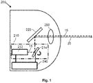
- Fig. 1 shows a principal sketch of a vehicle headlight system 200.
- the vehicle headlight system 200 comprises at least one laser 212.
- the at least one laser 212 is adapted to emit laser light 15 with a laser peak emission wavelength.
- the peak emission wavelength is preferably in the blue wavelength range.
- the vehicle headlight system 200 further comprises a light converter 220.
- the light converter 220 is adapted to convert the laser light 15 to converted light 20, wherein a peak emission wavelength of the converted light 20 is in a longer wavelength range than the laser peak emission wavelength.
- the peak emission wavelength of the converted light 20 is preferably in the yellow wavelength range.
- the vehicle headlight system 200 further comprises a scanner 214.
- the scanner 214 is adapted to provide a light pattern comprising a multitude of scanlines on the light converter 220.
- the at least one laser 212 and the scanner 214 are arranged in a scanning laser arrangement 210 which is coupled to a controller 240 which is in this case an integrated part of the vehicle headlight system 200.
- the vehicle headlight system 200 may be part of a vehicle headlight.
- the scanner is in this case a MEMS micro mirror.
- the controller 240 is adapted to control a cut-off of the light pattern by changing a position of at least one scanline with respect to a reference illumination pattern.
- the controller 240 is arranged to control the micro mirror such that a position of the scanline on the light converter 220 is shifted.
- an illumination pattern comprising a mixture of laser light 15 and converted light 20 which is projected by means of an optical arrangement 250 can be changed.
- the optical arrangement 250 may comprise one, two, three or more optical elements like lenses, mirrors, apertures and the like.
- the controller 240 is further arranged to dim the laser light 15 or to adapt the intensity of the laser light 15 in order to provide a smooth illumination pattern.
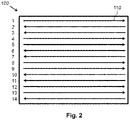
- Fig. 2 shows a principal sketch of a first illumination pattern 100.
- the normal approach to create the image on the phosphor is by line scanning.
- Fig. 2 shows a straightforward line-scanning pattern.
- the scanlines 110 have a defined scanline width which is essentially defined by a diameter of the laser spot on the light converter essentially perpendicular to a scanning direction indicated by the arrows.
- the first illumination pattern 100 shows a reference illumination pattern in which no adaption of the scanlines 110 has been performed in order to adapt the illumination pattern to an object which may appear in an area illuminated by the illumination pattern 100.
- Fig. 3 shows a principal sketch of a second illumination pattern 100.
- the second illumination pattern 100 is again a reference illumination pattern with 11 scanlines 110.
- the abscissa 102 denotes the number of the scanline 110.
- the ordinate 101 shows the relative position of the respective scanline 110 on the light converter.
- the scanlines 110 have a scanline width 113 as described above and a distance between two scanlines 110 is given by X0 which is in this case the same for all scanlines 110.
- the scanlines 110 overlap such that the light converter is illuminated by means of laser light of two scanlines 110 up to the upper and lower edge (first and eleventh scanline) of the light converter.
- the scanlines 110 may, for example, be scanned one after the other (non-interleaving) or in an interleaving sequence, e.g. as described above. The numbering does not necessarily describe the sequence of scanning.
- the reference illumination patterns shown in Fig. 2 and Fig. 3 show simple examples of reference illumination patterns.
- the distance between the scanlines has not to be the same.
- one or more of the scanlines 110 may be curved or may comprise even corners in order to provide more complicated reference illumination patterns.
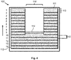
- Fig. 4 shows a principal sketch of a third illumination pattern 100.
- the third illumination pattern 100 is generated by means of a first embodiment of the inventive method.
- the third illumination pattern 100 comprises 14 scanlines 110 wherein scanlines 1-9 are non-continuous scanlines 111 and scanlines 10-14 are continuous scanlines 112.
- the illumination pattern 100 comprises an illumination window 116.
- the illumination window 116 is generated by switching off in subsequent steps a part of the first, second, third etc. scanlines 110 such that the illumination pattern 100 becomes U-shaped.
- a dashed line shows a cut-off 114 within the illumination window 116 before the respective part of scanline 9 was switched off.
- the distance between the scanlines 110 is again X0 and the scanline width is 113.
- the change or shift of the cut-off 114 is reduced by moving or shifting all scanlines 110 around one third of a scanline width 113 to the top as indicated by the arrow on the left side as soon as the part of the ninth scanline 110 is switched off.
- the shift of the scanlines 110 is preferably performed in a way that original characteristic (straight line in this case) is not changed. The shift may therefore be performed during a step between two scanlines 110.
- the laser may be switched off in this intermediate phase. This is preferably performed in all embodiments comprising a change of a position of a scanline 110.
- Fig. 5 shows a principal sketch of a fourth illumination pattern 100.
- the fourth illumination pattern 100 is generated by means of the inventive method according to a second embodiment.
- the illumination pattern 100 is again U-shaped as described with respect to Fig. 4 .
- the distance between continuous scanlines 112 (scanlines 10-14) is increased from X0 to X1 as soon as a part of scanline 9 is switched off in order to reduce the shift of the cut off 114.
- the distance between the non-continuous scanlines 111 is unchanged (X0).
- Fig. 6 shows a principal sketch of a fifth illumination pattern 100 generated by means of the inventive method according to a third embodiment.
- Fig. 6 shows a kind of side view of the illumination pattern 100 as already shown and discussed with respect to Fig. 3 .
- the illumination pattern 100 is again U-shaped.
- the distance between continuous scanlines 112 (scanlines 1-4) is increased from X0 to X1 as soon as a part of scanline 5 is switched off in order to reduce the shift of the cut-off (not shown).
- the distance between the non-continuous scanlines 111 is additionally decreased from X0 to X2.
- Fig. 7 shows a principal sketch of a sixth illumination pattern 100 generated by means of the inventive method according to a fourth embodiment.
- the sixth illumination pattern 100 comprises 14 scanlines 110 wherein scanlines 3-9 are non-continuous scanlines 111 and scanlines 1, 2 and 10-14 are continuous scanlines 112.
- the illumination pattern 100 comprises an illumination window 116.
- the illumination window 116 is generated by switching off in subsequent steps a part of the third, fourth, fifth etc. scanline such that the illumination pattern 100 becomes O-shaped.
- a dashed line shows a cut-off 114 within the illumination window 116 before the respective part of scanline 9 was switched off.
- the distance between the continuous scanlines 112 is again X0 and the scanline width is 113.
- the change or shift of the cut-off 114 is at least subjectively reduced by providing a small gap in in the ninth scanline between a first part 9a and a second part 9b.
- the gap is increased step-by-step along a longitudinal extension of the ninth scanline as indicated by the double arrow.
- the dark parts in the third, fourth and fifth scanlines may be opened in the same way in a step by step approach one after the other in order to open the window 116. Alternatively, two, three, four or more scanlines may be darkened simultaneously.
Landscapes
- Engineering & Computer Science (AREA)
- General Engineering & Computer Science (AREA)
- Physics & Mathematics (AREA)
- Optics & Photonics (AREA)
- Mechanical Engineering (AREA)
- Microelectronics & Electronic Packaging (AREA)
- Lighting Device Outwards From Vehicle And Optical Signal (AREA)
- Mechanical Optical Scanning Systems (AREA)
Description
- The invention relates to a laser scanning method of providing an adaptive illumination pattern for vehicle lighting. The invention further relates to a vehicle headlight system comprising a laser scanner being arranged to perform the method. The invention finally relates to a corresponding computer program product.
- In modern automotive headlighting, a strong trend goes to adaptive systems where the light distribution can be changed dynamically. For example one would like to have a high-beam bundle, but with a well-defined and moving dark section to spare out an oncoming car, to avoid glare. Or one would like to illuminate a given road sign, or an obstacle that the car's camera could have detected.
- Technically, such systems can be realized with different approaches, with increasing performance, but also complexity: switchable mechanical apertures, LED matrix lights, micro-displays (as in beamers), or laser scanners.
- As an example,
DE102010028949A1 discloses a laser based headlight scanning a laser beam in a fixed pattern over a luminescent material which is then mapped by a secondary optics onto the road.DE102010028949A1 stresses that, principally, such arrangement can obtain a very high resolution of up to 1000 x 1000 pixels. In particular, such high resolution allows adjusting the position of the bright/dark cut-offline of a low beam to an accuracy of up to 0.1° just by appropriately setting the row signal for the laser scanner. Other headlights are known fromWO 2014/121315 A1 andWO 2016/021154 A1 . - It is an object of the present invention to provide a laser scanning method of providing an adaptive illumination pattern for vehicle lighting. The method may beneficially be used in a vehicle headlight as, for example, an automotive headlight or a headlight of a motorbike.
- According to a first aspect, the invention comprises a method of providing an illumination pattern for vehicle lighting. The method comprises the steps of:
- providing a light pattern comprising a multitude of scanlines of white light by illuminating a light converter by means of a scanning laser arrangement for illuminating an area, wherein the scanlines are characterized by a defined scanline width;
- adapting a cut-off of the light pattern by changing a position of at least one scanline with respect to a reference illumination pattern.
- The scanning laser arrangement may comprise, for example, a blue laser. The blue laser is adapted to emit a blue laser beam, which can be electronically switched and direction-controlled by a small mirror, typically a MEMS (micro electromechanical system). In this way, the laser beam is quickly steered in scanlines over a surface of a light converter. The scanlines are lines of the spot of the laser beam on the surface of the light converter. The scanlines may be continuous or non-continuous scanlines. The scanlines may be straight, curved or may even comprise a buckling or corner. The scanlines are usually arranged such that two adjacent scanlines overlap to a defined extent on the surface of the light converter. The overlap may be half of a scanline width, wherein the scanline width is given by a spot size of the laser beam. The overlap may alternatively be 1/3, ¼, 2/3 or the like of the scanline width.
- The surface of the converter device may comprise a phosphor surface partially converting the blue laser light to yellow light, which adds up with the remaining blue light to form white light. If the movement of the white-light spot on the phosphor surface is fast enough, it is perceived as a steady white-light distribution or image. This image is then projected onto, for example, a road through a lens, as in standard projection headlamps. By a control of the mirror movement, synchronized with suitable switching of the laser beam (on and off, different intensities), a large variety of images on the phosphor, and thus light distributions on the road, can be created.
- It is important to note two special features of such scanning laser arrangements. These two special features are due to the high power, and thus non-negligible beam diameter of such systems. First, the spot size will not be negligible; it will probably not shrink below e.g. 200-300 µm. This is only about a factor of 10 smaller than the smallest dimension of the phosphor target of the light converter of e.g. 3 mm. Second, the beam-steering mirror will have a limited scan speed because of its finite size (of e.g. 2 mm as partly caused by the high laser power). Also, as it has to be controllable in a flexible manner (changing line patterns), it cannot be very fast either, due to mechanical constraints. Since the frame repetition rate must be high (e.g. 100 Hz) to avoid flicker, the time per frame is limited to e.g. 10 ms. Given the slow scan speed of flexible mirrors, the number of lines in such systems will be small, e.g. 11, 14 or 20 lines. This matches the fact that the beam diameter has to be large as the complete height of the phosphor target needs to be covered with, for example, only 20 lines. In such a setup, dark zones in the illumination pattern can be easily created by switching off the laser at the right moments.
- The problem, however, is the low resolution that the system will achieve in the vertical direction essentially perpendicular to the main direction of movement of the laser spot on the surface of the converter device. Eleven or fourteen segments might appear still good enough for automotive headlighting, but moving horizontal edges which define a cut-off of the light pattern can only be moved in steps, by switching off portions of one line after the other. These steps may make the image appear very unsteady and disturbing for the traffic participants. Therefore, it is desirable to be able to move horizontal edges smoother, without revealing the poor native vertical resolution of the system. It is therefore proposed to change a position of at least one scanline with respect to a reference illumination pattern or to dim at least a limited portion of at least one scanline.
- The reference illumination pattern comprises all scanlines in which, for example, no adaption to a time varying situation such as an approaching vehicle of approaching traffic has been performed. The reference pattern may depend on an illumination mode (e.g. low beam or high beam).
- The illumination pattern is adapted such that in case of a necessary adaption (e.g. approaching traffic, traffic sign) a cut-off which is part of an area which is not illuminated by the light pattern is changed in a smoother way. A cut-off may be adapted by simultaneously changing the position of all scanlines in comparison to the reference illumination pattern. The whole illumination pattern may in this case be adapted by elevating or lowering the cut-off.
- The step of adapting the cut-off of the light pattern by changing the position of at least one scanline comprises the step of:
- switching off at least a part of a scanline to provide a non-continuous scanline.
- It may be necessary in some situations to adapt the light pattern provided by means of the laser light or laser beam and the light converter by providing or adapting a window or more generally a dark zone in the light pattern in order to avoid, for example, glare of, for example, other traffic participants. Parts of one, two, three or more scanlines may therefore be switched off. Several scanlines may, for example, be subsequently switched off.
- The method further comprises the additional step of:
- illuminating an area previously illuminated by the non-continuous scanline (before switching off at least a part of the scanline) by changing a position of a continuous scanline adjacent to the non-continuous scanline.
- Changing the position of at least one continuous scanline with respect to the reference illumination pattern enables a shift of the cut-off such that the shift is smaller in comparison to the case that only at least a part of the scanline in the reference illumination pattern is switched off. The continuous scanline adjacent to the non-continuous scanline is shifted such that a part of an area previously illuminated by the switched-off part of the non-continuous scanline is now illuminated by the adjacent continuous scanline. The position of the continuous scanline adjacent to the non-continuous scanline is essentially shifted perpendicular to the scanning direction of the laser spot.
- The position of the scanline adjacent to the non-continuous scanline may be changed or shifted by expanding a distance between at least two continuous scanlines, wherein one of the at least two continuous scanlines is the continuous scanline adjacent to the non-continuous scanline.
- The distance between adjacent scanlines in the reference illumination pattern may be the same or may be different across the reference illumination pattern. An area previously illuminated by means of the scanline which is switched off is illuminated by means of at least one continuous scanline, the continuous scanline being adjacent to the non-continuous scanline. The distance between two, three, four or more neighboring or adjacent continuous scanlines below or above the cut-off is increased in comparison to the distance between those scanlines in the reference pattern. The distance between the continuous scanlines below or above the cut-off may be decreased in a subsequent step in order to shift the cut-off.
- The method may comprise the additional step of:
- stepwise decreasing the distance between the at least two scanlines in a subsequent step after expanding the distance.
- The distance between the two, three, four or more continuous scanlines below or above the cut-off may be decreased step-by-step such that the original distance (as in the reference illumination pattern) is reached after two, three, four or more steps in order to shift the cut-off smoothly. The edge of the cut-off is shifted to many intermediate positions in between the positions which are given by the reference illumination pattern. The change of the distance between continuous scanlines may not be the same for all continuous scanlines. The change of the distance may, for example, be bigger between the adjacent continuous scanline (first continuous scanline) and the continuous scanline directly above or below the adjacent continuous scanline (second continuous scanline) than the change of the distance between the second continuous scanline and a further continuous scanline above or below the second continuous scanline (third continuous scanline). The different distance adaptions may help to avoid or at least limit visible intensity variations in the illumination pattern. This also comprises the case that there may be an adaptable upper cut-off (in the upper part of the illumination pattern) and an adaptable lower cut-off (in the lower part of the illumination pattern). Such an illumination pattern may, for example, comprise the case that only the fourth, fifth, sixth, seventh and eighth scanline of 20 scanlines are non-continuous scanlines. The positions of the non-continuous scanlines in between the upper cut-off and the lower cut-off may, for example, be changed such that a position of a non-continuous scanline in the middle, e.g. sixth scanline in the example, between the upper cut-off and the lower cut-off is nearly unchanged but the distance between the fourth and the fifth scanline is essentially the same as the distance between the seventh and eighth but the distance between the fifth and sixth scanline and the sixth and seventh is smaller.
- The method as described above may comprise the additional steps of:
- providing at least two adjacent non-continuous scanlines; and
- decreasing a distance between the at least two adjacent non-continuous scanlines.
- Increasing the distance between the continuous scanlines may have the effect that there may be a bright line in the illumination pattern at the overlap of the continuous scanline adjacent to the window or more general the dark zone of the illumination pattern and the neighboring non-continuous scanline. The distance between the non-continuous scanline next to the cut-off and at least an adjacent non-continuous scanline may therefore be decreased such that an overlap between the non-continuous scanline next to the cut-off and the continuous scanline defining the cut-off is reduced. The distance between two, three, four or more non-continuous scanlines may be decreased in order to smoothen an intensity distribution of the illumination pattern. The distance between the two, three, four or more non-continuous scanlines may be changed depending on the distance of the respective non-continuous scanline to the cutoff. The change of the distance may, for example, be smaller between the non-continuous scanline at the cut-off (first non-continuous scanline) and the non-continuous scanline directly above or below the first non-continuous scanline (second non-continuous scanline) than the change of the distance between the second non-continuous scanline and a further non-continuous scanline (third non-continuous scanline) above or below the second non-continuous scanline. The different distance adaptions may help to avoid or at least limit visible intensity variations in the illumination pattern.
- The method may further comprise the additional step of:
- adapting an intensity of at least one scanline such that an integral intensity of at least two adjacent scanlines is adapted to the change of the distance between the two adjacent scanlines.
- The expansion or compression of the scanline pattern on a region of the light converter will change the "density" of the scanlines as described above. Therefore the apparent brightness may change in a visible way. (Note that the boundaries between the lines are normally not visible in practice, due to the generous overlap of adjacent beams). The changes in brightness due to the deliberate "breathing", i.e. the compression and expansion of the scanline pattern, will be small but also periodic, so that they could be perceived as flicker, which may be equally disturbing as a "jumping" horizontal edge or cut-off. To compensate for this, the laser intensity may be slightly increased where the line pattern is expanded, and decreased where it is compressed. The intensity of each scanline may be adapted individually. The variation of the intensity may be determined by means of a change of the overlap between adjacent scanlines and/or intensity variations of adjacent scanlines (either continuous or non-continuous scanlines).
- The step of switching off at least a part of a scanline may alternatively or in addition comprise the step of:
- providing a gap in the at least one scanline; and
- increasing the gap along a longitudinal extension of the at least one scanline.
- A small gap may be provided in a continuous scanline in a first run by shortly switching off the laser. The gap is increased step-by-step in the scanning direction or along the scanline in a second, third, fourth or a further run. The dark area or zone within the illumination pattern increases like an opening curtain.
- According to a further aspect a vehicle headlight system is provided. The vehicle headlight system comprises at least one laser. The at least one laser is adapted to emit laser light with a laser peak emission wavelength. The vehicle headlight system further comprises a light converter. The light converter is adapted to convert the laser light to converted light, wherein a peak emission wavelength of the converted light is in a longer wavelength range than the laser peak emission wavelength. The vehicle headlight system further comprises a scanner. The scanner is adapted to provide a light pattern comprising a multitude of scanlines on the light converter. The vehicle headlight system further comprises a controller, wherein the controller is adapted to control a cut-off of the light pattern by changing a position of at least one scanline with respect to a reference illumination pattern.
- The vehicle headlight system may comprise two, three, four or more lasers. The scanner may comprise a dynamic mirror as, for example, a MEMS mirror in order to provide or project the scanlines on the light converter. The light converter may comprise a conversion element comprising a phosphor for converting, for example, at least a part of the blue laser light to yellow light. The phosphor may, for example, be a ceramic block of Cerium doped Yttrium-Aluminum-Garnet (YAG). The controller may be adapted to control the scanner and/or the laser in order to change or shift the position of the scanlines or to dim the at least one laser as described above. The controller may be an integrated part of a vehicle headlight or an external control device connected to the vehicle headlight. The controller may comprise an interface to connect the vehicle headlight system to a vehicle control system.
- According to a further aspect is a computer program product provided. The computer program product comprises code means which can be saved on at least one memory device comprised by the inventive vehicle headlight system or on at least one memory device of a control device coupled with the vehicle headlight system, wherein the code means being arranged such that the inventive method can be executed by means of at least one processing device comprised by the vehicle headlight system or by means of at least one processing device of the control device coupled with the vehicle headlight system.
- The at least one memory device may comprise one or more memory modules as, for example, memory chips. The at least one processing device may comprise one or more processors or microprocessors. The at least one memory device and/or the at least one processing device may be comprised by the controller.
- Further advantageous embodiments are defined below.
- These and other aspects of the invention will be apparent from and elucidated with reference to the embodiments described hereinafter.
- The invention will now be described, by way of example, based on embodiments with reference to the accompanying drawings.
- In the drawings:
-
Fig. 1 shows a principal sketch of a vehicle headlight system -
Fig. 2 shows a principal sketch of a first illumination pattern -
Fig. 3 shows a principal sketch of a second illumination pattern -
Fig. 4 shows a principal sketch of third illumination pattern -
Fig. 5 shows a principal sketch of fourth illumination pattern -
Fig. 6 shows a principal sketch of a fifth illumination pattern -
Fig. 7 shows a principal sketch of sixth illumination pattern - In the Figures, like numbers refer to like objects throughout. Objects in the Figures are not necessarily drawn to scale.
-
Fig. 1 shows a principal sketch of avehicle headlight system 200. Thevehicle headlight system 200 comprises at least onelaser 212. The at least onelaser 212 is adapted to emitlaser light 15 with a laser peak emission wavelength. The peak emission wavelength is preferably in the blue wavelength range. Thevehicle headlight system 200 further comprises alight converter 220. Thelight converter 220 is adapted to convert thelaser light 15 to converted light 20, wherein a peak emission wavelength of the convertedlight 20 is in a longer wavelength range than the laser peak emission wavelength. The peak emission wavelength of the convertedlight 20 is preferably in the yellow wavelength range. Thevehicle headlight system 200 further comprises a scanner 214. The scanner 214 is adapted to provide a light pattern comprising a multitude of scanlines on thelight converter 220. The at least onelaser 212 and the scanner 214 are arranged in ascanning laser arrangement 210 which is coupled to acontroller 240 which is in this case an integrated part of thevehicle headlight system 200. Thevehicle headlight system 200 may be part of a vehicle headlight. The scanner is in this case a MEMS micro mirror. Thecontroller 240 is adapted to control a cut-off of the light pattern by changing a position of at least one scanline with respect to a reference illumination pattern. Thecontroller 240 is arranged to control the micro mirror such that a position of the scanline on thelight converter 220 is shifted. Hence, an illumination pattern comprising a mixture oflaser light 15 and converted light 20 which is projected by means of anoptical arrangement 250 can be changed. Theoptical arrangement 250 may comprise one, two, three or more optical elements like lenses, mirrors, apertures and the like. Thecontroller 240 is further arranged to dim thelaser light 15 or to adapt the intensity of thelaser light 15 in order to provide a smooth illumination pattern. -
Fig. 2 shows a principal sketch of afirst illumination pattern 100. The normal approach to create the image on the phosphor is by line scanning.Fig. 2 shows a straightforward line-scanning pattern. There are 14 scanlines, and the laser jumps downward fromline 1 toline 3, from 3 to 5, etc., leaving gaps which are filled on the way back upwards (well-known "interleaving"). Thescanlines 110 have a defined scanline width which is essentially defined by a diameter of the laser spot on the light converter essentially perpendicular to a scanning direction indicated by the arrows. Thefirst illumination pattern 100 shows a reference illumination pattern in which no adaption of thescanlines 110 has been performed in order to adapt the illumination pattern to an object which may appear in an area illuminated by theillumination pattern 100. -
Fig. 3 shows a principal sketch of asecond illumination pattern 100. Thesecond illumination pattern 100 is again a reference illumination pattern with 11scanlines 110. Theabscissa 102 denotes the number of thescanline 110. Theordinate 101 shows the relative position of therespective scanline 110 on the light converter. Thescanlines 110 have ascanline width 113 as described above and a distance between twoscanlines 110 is given by X0 which is in this case the same for all scanlines 110. Thescanlines 110 overlap such that the light converter is illuminated by means of laser light of twoscanlines 110 up to the upper and lower edge (first and eleventh scanline) of the light converter. Thescanlines 110 may, for example, be scanned one after the other (non-interleaving) or in an interleaving sequence, e.g. as described above. The numbering does not necessarily describe the sequence of scanning. - The reference illumination patterns shown in
Fig. 2 andFig. 3 show simple examples of reference illumination patterns. In general, the distance between the scanlines has not to be the same. Furthermore, one or more of thescanlines 110 may be curved or may comprise even corners in order to provide more complicated reference illumination patterns. -
Fig. 4 shows a principal sketch of athird illumination pattern 100. Thethird illumination pattern 100 is generated by means of a first embodiment of the inventive method. Thethird illumination pattern 100 comprises 14scanlines 110 wherein scanlines 1-9 arenon-continuous scanlines 111 and scanlines 10-14 arecontinuous scanlines 112. Theillumination pattern 100 comprises anillumination window 116. Theillumination window 116 is generated by switching off in subsequent steps a part of the first, second, third etc.scanlines 110 such that theillumination pattern 100 becomes U-shaped. A dashed line shows a cut-off 114 within theillumination window 116 before the respective part ofscanline 9 was switched off. The distance between thescanlines 110 is again X0 and the scanline width is 113. The change or shift of the cut-off 114 is reduced by moving or shifting allscanlines 110 around one third of ascanline width 113 to the top as indicated by the arrow on the left side as soon as the part of theninth scanline 110 is switched off. The shift of thescanlines 110 is preferably performed in a way that original characteristic (straight line in this case) is not changed. The shift may therefore be performed during a step between twoscanlines 110. The laser may be switched off in this intermediate phase. This is preferably performed in all embodiments comprising a change of a position of ascanline 110. -
Fig. 5 shows a principal sketch of afourth illumination pattern 100. Thefourth illumination pattern 100 is generated by means of the inventive method according to a second embodiment. Theillumination pattern 100 is again U-shaped as described with respect toFig. 4 . The distance between continuous scanlines 112 (scanlines 10-14) is increased from X0 to X1 as soon as a part ofscanline 9 is switched off in order to reduce the shift of the cut off 114. The distance between thenon-continuous scanlines 111 is unchanged (X0). -
Fig. 6 shows a principal sketch of afifth illumination pattern 100 generated by means of the inventive method according to a third embodiment.Fig. 6 shows a kind of side view of theillumination pattern 100 as already shown and discussed with respect toFig. 3 . Theillumination pattern 100 is again U-shaped. The distance between continuous scanlines 112 (scanlines 1-4) is increased from X0 to X1 as soon as a part ofscanline 5 is switched off in order to reduce the shift of the cut-off (not shown). The distance between the non-continuous scanlines 111 (scanlines 5-11) is additionally decreased from X0 to X2. -
Fig. 7 shows a principal sketch of asixth illumination pattern 100 generated by means of the inventive method according to a fourth embodiment. Thesixth illumination pattern 100 comprises 14scanlines 110 wherein scanlines 3-9 arenon-continuous scanlines 111 andscanlines continuous scanlines 112. Theillumination pattern 100 comprises anillumination window 116. Theillumination window 116 is generated by switching off in subsequent steps a part of the third, fourth, fifth etc. scanline such that theillumination pattern 100 becomes O-shaped. A dashed line shows a cut-off 114 within theillumination window 116 before the respective part ofscanline 9 was switched off. The distance between thecontinuous scanlines 112 is again X0 and the scanline width is 113. The change or shift of the cut-off 114 is at least subjectively reduced by providing a small gap in in the ninth scanline between afirst part 9a and asecond part 9b. The gap is increased step-by-step along a longitudinal extension of the ninth scanline as indicated by the double arrow. The dark parts in the third, fourth and fifth scanlines may be opened in the same way in a step by step approach one after the other in order to open thewindow 116. Alternatively, two, three, four or more scanlines may be darkened simultaneously. - While the invention has been illustrated and described in detail in the drawings and the foregoing description, such illustration and description are to be considered illustrative or exemplary and not restrictive. In the claims, the word "comprising" does not exclude other elements or steps, and the indefinite article "a" or "an" does not exclude a plurality of elements or steps.
- Any reference signs in the claims should not be construed as limiting the scope thereof.
-
- 9a
- first part of a non-continuous scanline
- 9b
- second part of a non-continuous scanline
- 15
- laser light
- 20
- converted light
- 100
- illumination pattern
- 101
- position of scanline on the light converter
- 102
- number of scanline
- 110
- scanline
- 111
- non-continuous scanline
- 112
- continuous scanline
- 113
- scanline width
- 114
- cut-off
- 116
- illumination window
- 200
- vehicle headlight system
- 210
- scanning laser arrangement
- 212
- laser
- 214
- scanner
- 220
- light converter
- 240
- controller
- 250
- optical arrangement
- X0
- distance between scanlines in reference illumination pattern
- X1
- increased distance between two continuous scanlines
- X2
- decreased distance between two non-continuous scanlines
Claims (9)
- A method of providing an illumination pattern (100) for vehicle lighting, the method comprising the steps of:- providing a light pattern comprising a multitude of adjacent scanlines (110) of white light, being arranged in a reference illumination pattern, by illuminating a light converter (220) by means of a scanning laser arrangement (210) for illuminating an area, wherein the scanlines (110) have a defined scanline width (113), characterized by- adapting a cut-off (114) of the light pattern by switching off at least a part of a scanline (111) to provide a non-continuous scanline (111) and by illuminating an area previously illuminated by the non-continuous scanline (111) by controlling the scanning laser arrangement (210) for changing a position of a continuous scanline (112) adjacent to the non-continuous scanline (111) with respect to the reference illumination pattern, wherein the adjacent scanlines (110) overlap with each other.
- The method according to claim 1, wherein the position of the continuous scanline (112) adjacent to the non-continuous scanline (111) is changed by expanding a distance between at least two continuous scanlines, wherein one of the at least two continuous scanlines is the continuous scanline (112) adjacent to the non-continuous scanline (111).
- The method according to claim 2, wherein the method comprises the additional step of:- stepwise decreasing the distance between the at least two scanlines in a subsequent step after expanding the distance.
- The method according to claim 1 or 2, wherein the method comprises the additional step of:- providing at least two adjacent non-continuous scanlines (111); and- decreasing a distance between the at least two adjacent non-continuous scanlines (111).
- The method according to claim 1 or 2, wherein the method comprises the additional step of:- adapting an intensity of at least one scanline (110) such that an integral intensity of at least two adjacent scanlines (110) is adapted to a change of a distance between the two adjacent scanlines (110).
- The method according to claim 1 or 2, wherein the position of the continuous scanline (112) adjacent to the non-continuous scanline (111) is changed by simultaneously changing a position of all the scanlines (110).
- The method according to claim 1 or 2, wherein the step of switching off at least a part of a scanline (111) comprises the step of:- providing a gap (116) in the at least one scanline (111); and- increasing the gap (116) along a longitudinal extension of the at least one scanline (111).
- A vehicle headlight system (200) comprising:- at least one laser (212), wherein the at least one laser (212) is adapted to emit laser light (15) with a laser peak emission wavelength,- a light converter (220), wherein the light converter (220) is adapted to convert the laser light (15) to converted light (20), wherein a peak emission wavelength of the converted light (20) is in a longer wavelength range than the laser peak emission wavelength,- a scanner (214), wherein the scanner (214) is adapted for illuminating the light converter (220) to provide a light pattern comprising a multitude of adjacent scanlines (110) of white light, being arranged in a reference illumination pattern, wherein the scanlines (110) have a defined scanline width (113),- a controller (240), wherein the controller (240) is adapted to control a cut-off (114) of the light pattern by switching off at least a part of a scanline (111) to provide a non-continuous scanline (111), characterized in that the controller (240) is adapted to illuminate an area previously illuminated by the non-continuous scanline (111) by controlling the scanner (214) for changing a position of a continuous scanline (112) adjacent to the non-continuous scanline (111) with respect to the reference illumination pattern, wherein the adjacent scanlines (110) overlap each other.
- A computer program product comprising code means which can be saved on at least one memory device comprised by the vehicle headlight system (200) according to claim 8 or on at least one memory device of a control device coupled with the vehicle headlight system (200) according to claim 8, characterized in that the code means are arranged such that the
method according to anyone of claims 1 to 7 can be executed by means of at least one processing device comprised by the vehicle headlight system (200) according to claim 8 or by means of at least one processing device of the control device coupled with the vehicle headlight system (200) according to claim 8.
Applications Claiming Priority (2)
| Application Number | Priority Date | Filing Date | Title |
|---|---|---|---|
| EP16180400 | 2016-07-20 | ||
| PCT/EP2017/067574 WO2018015248A1 (en) | 2016-07-20 | 2017-07-12 | Adaptive illumination method for vehicle headlight |
Publications (2)
| Publication Number | Publication Date |
|---|---|
| EP3488146A1 EP3488146A1 (en) | 2019-05-29 |
| EP3488146B1 true EP3488146B1 (en) | 2022-09-07 |
Family
ID=56550063
Family Applications (1)
| Application Number | Title | Priority Date | Filing Date |
|---|---|---|---|
| EP17736691.1A Active EP3488146B1 (en) | 2016-07-20 | 2017-07-12 | Adaptive illumination method for vehicle headlight |
Country Status (5)
| Country | Link |
|---|---|
| US (1) | US11208030B2 (en) |
| EP (1) | EP3488146B1 (en) |
| JP (1) | JP7026096B2 (en) |
| CN (1) | CN109476255B (en) |
| WO (1) | WO2018015248A1 (en) |
Families Citing this family (1)
| Publication number | Priority date | Publication date | Assignee | Title |
|---|---|---|---|---|
| US10771155B2 (en) | 2017-09-28 | 2020-09-08 | Soraa Laser Diode, Inc. | Intelligent visible light with a gallium and nitrogen containing laser source |
Citations (2)
| Publication number | Priority date | Publication date | Assignee | Title |
|---|---|---|---|---|
| EP2567866A2 (en) * | 2011-09-07 | 2013-03-13 | Audi Ag | Method for operating a headlight on a motor vehicle |
| EP2918446A1 (en) * | 2014-03-12 | 2015-09-16 | Audi Ag | System and method for controlling a vehicle headlight |
Family Cites Families (26)
| Publication number | Priority date | Publication date | Assignee | Title |
|---|---|---|---|---|
| EP1722159A4 (en) * | 2004-02-25 | 2008-01-23 | Hitachi Ltd | VEHICLE HEADLIGHTS AND VEHICLE SUPPLY SUPPORT |
| US7839560B2 (en) * | 2006-12-29 | 2010-11-23 | Texas Instruments Incorporated | Packaged spatial light modulator and a display system using the same |
| JP4881255B2 (en) | 2007-08-13 | 2012-02-22 | 株式会社小糸製作所 | Vehicle headlamp |
| JP5141580B2 (en) * | 2009-01-30 | 2013-02-13 | 市光工業株式会社 | Vehicle headlamp |
| JP5577138B2 (en) * | 2010-04-08 | 2014-08-20 | スタンレー電気株式会社 | Vehicle headlamp |
| DE102010028949A1 (en) | 2010-05-12 | 2011-11-17 | Osram Gesellschaft mit beschränkter Haftung | headlight module |
| JP5758717B2 (en) * | 2011-06-22 | 2015-08-05 | スタンレー電気株式会社 | Vehicle lighting device |
| JP2013047091A (en) * | 2011-07-25 | 2013-03-07 | Sharp Corp | Lighting device and vehicle headlamp including the same |
| JP5910116B2 (en) | 2012-01-30 | 2016-04-27 | マツダ株式会社 | Headlight control device |
| US9534756B2 (en) * | 2012-04-03 | 2017-01-03 | Sharp Kabushiki Kaisha | Light-emitting device, floodlight, and vehicle headlight |
| FR2993831B1 (en) * | 2012-07-27 | 2015-07-03 | Valeo Vision | ADAPTIVE LIGHTING SYSTEM FOR MOTOR VEHICLE |
| WO2014024385A1 (en) | 2012-08-08 | 2014-02-13 | 株式会社小糸製作所 | Vehicle lamp fitting |
| JP6180091B2 (en) * | 2012-09-07 | 2017-08-16 | 株式会社小糸製作所 | Vehicle lighting |
| AT514834B1 (en) | 2013-02-07 | 2017-11-15 | Zkw Group Gmbh | Headlight for a motor vehicle and method for generating a light distribution |
| AT513916B1 (en) * | 2013-02-07 | 2015-04-15 | Zizala Lichtsysteme Gmbh | Headlight for a motor vehicle and method for generating a light distribution |
| DE102013226652A1 (en) | 2013-12-19 | 2015-06-25 | Osram Gmbh | Operating a lighting device with multiple light generating devices |
| JP6360699B2 (en) * | 2014-03-25 | 2018-07-18 | スタンレー電気株式会社 | head lamp |
| JP2016038966A (en) | 2014-08-06 | 2016-03-22 | パナソニックIpマネジメント株式会社 | Lighting device and car equipped with it |
| US9826203B2 (en) | 2014-09-08 | 2017-11-21 | Intel Corporation | Method and system for controlling a laser-based lighting system |
| JP6354502B2 (en) | 2014-09-30 | 2018-07-11 | セイコーエプソン株式会社 | Light source device and projector |
| JP6427851B2 (en) | 2014-10-21 | 2018-11-28 | スタンレー電気株式会社 | Vehicle lighting |
| EP3216650A4 (en) * | 2014-11-07 | 2018-06-13 | Dai Nippon Printing Co., Ltd. | Lighting device |
| DE102014017919A1 (en) | 2014-12-04 | 2016-06-09 | Audi Ag | Method for operating a lighting device of a motor vehicle, lighting device and motor vehicle |
| AT516848B1 (en) * | 2015-04-27 | 2016-09-15 | Zizala Lichtsysteme Gmbh | Method for driving a light scanner in a headlight for vehicles and headlights |
| US10436409B2 (en) * | 2015-05-28 | 2019-10-08 | Texas Instruments Incorporated | Methods and apparatus for light efficient programmable headlamp with anamorphic optics |
| DE102018102575B4 (en) * | 2017-05-25 | 2024-03-07 | Hasco Vision Technology Co., Ltd. | Intelligent multi-function automotive headlight module |
-
2017
- 2017-07-12 US US16/318,657 patent/US11208030B2/en active Active
- 2017-07-12 CN CN201780044913.5A patent/CN109476255B/en active Active
- 2017-07-12 JP JP2019502781A patent/JP7026096B2/en active Active
- 2017-07-12 EP EP17736691.1A patent/EP3488146B1/en active Active
- 2017-07-12 WO PCT/EP2017/067574 patent/WO2018015248A1/en not_active Ceased
Patent Citations (2)
| Publication number | Priority date | Publication date | Assignee | Title |
|---|---|---|---|---|
| EP2567866A2 (en) * | 2011-09-07 | 2013-03-13 | Audi Ag | Method for operating a headlight on a motor vehicle |
| EP2918446A1 (en) * | 2014-03-12 | 2015-09-16 | Audi Ag | System and method for controlling a vehicle headlight |
Also Published As
| Publication number | Publication date |
|---|---|
| US11208030B2 (en) | 2021-12-28 |
| JP2019522592A (en) | 2019-08-15 |
| US20190283661A1 (en) | 2019-09-19 |
| CN109476255B (en) | 2022-06-14 |
| CN109476255A (en) | 2019-03-15 |
| JP7026096B2 (en) | 2022-02-25 |
| EP3488146A1 (en) | 2019-05-29 |
| WO2018015248A1 (en) | 2018-01-25 |
Similar Documents
| Publication | Publication Date | Title |
|---|---|---|
| JP6463507B2 (en) | Method for controlling optical scanner of vehicle projector | |
| KR102885444B1 (en) | Method and system for selectively adjusting pixels, in an optical module, in order to amend geometric defects due to manufacturing tolerances | |
| CN110225846B (en) | Vehicle lighting system, vehicle lighting control device and vehicle lighting control method | |
| US10309607B2 (en) | Lighting system | |
| US10119670B2 (en) | Headlight for vehicles | |
| CN106904117B (en) | Method for controlling a motor vehicle headlight | |
| US10801689B2 (en) | Method for controlling a motor vehicle headlight | |
| US10125940B2 (en) | Illumination device | |
| EP3096074B1 (en) | Vehicle lighting fixture | |
| US9897283B2 (en) | Generating a light emission pattern by illuminating a phosphor surface | |
| CN111376821A (en) | Vehicle lamp system, vehicle lamp control device, and vehicle lamp control method | |
| EP3733452A1 (en) | Vehicle lamp system, vehicle lamp control device, and vehicle lamp control method | |
| US20180259156A1 (en) | Lighting system and a lighting method | |
| KR102278904B1 (en) | Illumination device for a motor vehicle headlight | |
| CN114556016A (en) | Lighting device and homogenization method for a vehicle | |
| CN111486402B (en) | Vehicle lamp system, vehicle lamp control device, and vehicle lamp control method | |
| JP2022513956A (en) | How to control light patterns and automotive lighting equipment | |
| JP2022514389A (en) | How to correct light patterns and automotive lighting equipment | |
| EP3488146B1 (en) | Adaptive illumination method for vehicle headlight | |
| JP2023515964A (en) | Method and automotive lighting system for controlling light patterns | |
| JP7678133B2 (en) | Method for controlling a lighting pattern and lighting device for an automobile | |
| JPWO2016113818A1 (en) | LIGHTING DEVICE, VEHICLE, AND LIGHTING DEVICE CONTROL METHOD | |
| WO2018225684A1 (en) | Vehicle lamp system, control device for vehicle lamp, and control method for vehicle lamp | |
| JP7467720B2 (en) | Method for controlling adaptive vehicle headlights | |
| JP7648794B2 (en) | Method for controlling a lighting pattern and lighting device for an automobile |
Legal Events
| Date | Code | Title | Description |
|---|---|---|---|
| STAA | Information on the status of an ep patent application or granted ep patent |
Free format text: STATUS: UNKNOWN |
|
| STAA | Information on the status of an ep patent application or granted ep patent |
Free format text: STATUS: THE INTERNATIONAL PUBLICATION HAS BEEN MADE |
|
| PUAI | Public reference made under article 153(3) epc to a published international application that has entered the european phase |
Free format text: ORIGINAL CODE: 0009012 |
|
| STAA | Information on the status of an ep patent application or granted ep patent |
Free format text: STATUS: REQUEST FOR EXAMINATION WAS MADE |
|
| 17P | Request for examination filed |
Effective date: 20190220 |
|
| AK | Designated contracting states |
Kind code of ref document: A1 Designated state(s): AL AT BE BG CH CY CZ DE DK EE ES FI FR GB GR HR HU IE IS IT LI LT LU LV MC MK MT NL NO PL PT RO RS SE SI SK SM TR |
|
| AX | Request for extension of the european patent |
Extension state: BA ME |
|
| DAV | Request for validation of the european patent (deleted) | ||
| DAX | Request for extension of the european patent (deleted) | ||
| RAP1 | Party data changed (applicant data changed or rights of an application transferred) |
Owner name: LUMILEDS LLC |
|
| STAA | Information on the status of an ep patent application or granted ep patent |
Free format text: STATUS: EXAMINATION IS IN PROGRESS |
|
| 17Q | First examination report despatched |
Effective date: 20210419 |
|
| REG | Reference to a national code |
Ref country code: DE Ref legal event code: R079 Ref document number: 602017061500 Country of ref document: DE Free format text: PREVIOUS MAIN CLASS: F21S0041000000 Ipc: F21S0041675000 |
|
| RIC1 | Information provided on ipc code assigned before grant |
Ipc: F21S 41/663 20180101ALI20211115BHEP Ipc: F21S 41/675 20180101AFI20211115BHEP |
|
| GRAP | Despatch of communication of intention to grant a patent |
Free format text: ORIGINAL CODE: EPIDOSNIGR1 |
|
| STAA | Information on the status of an ep patent application or granted ep patent |
Free format text: STATUS: GRANT OF PATENT IS INTENDED |
|
| INTG | Intention to grant announced |
Effective date: 20220207 |
|
| GRAS | Grant fee paid |
Free format text: ORIGINAL CODE: EPIDOSNIGR3 |
|
| GRAA | (expected) grant |
Free format text: ORIGINAL CODE: 0009210 |
|
| STAA | Information on the status of an ep patent application or granted ep patent |
Free format text: STATUS: THE PATENT HAS BEEN GRANTED |
|
| AK | Designated contracting states |
Kind code of ref document: B1 Designated state(s): AL AT BE BG CH CY CZ DE DK EE ES FI FR GB GR HR HU IE IS IT LI LT LU LV MC MK MT NL NO PL PT RO RS SE SI SK SM TR |
|
| REG | Reference to a national code |
Ref country code: GB Ref legal event code: FG4D |
|
| REG | Reference to a national code |
Ref country code: CH Ref legal event code: EP Ref country code: AT Ref legal event code: REF Ref document number: 1517331 Country of ref document: AT Kind code of ref document: T Effective date: 20220915 |
|
| REG | Reference to a national code |
Ref country code: IE Ref legal event code: FG4D |
|
| REG | Reference to a national code |
Ref country code: DE Ref legal event code: R096 Ref document number: 602017061500 Country of ref document: DE |
|
| REG | Reference to a national code |
Ref country code: LT Ref legal event code: MG9D |
|
| REG | Reference to a national code |
Ref country code: NL Ref legal event code: MP Effective date: 20220907 |
|
| PG25 | Lapsed in a contracting state [announced via postgrant information from national office to epo] |
Ref country code: SE Free format text: LAPSE BECAUSE OF FAILURE TO SUBMIT A TRANSLATION OF THE DESCRIPTION OR TO PAY THE FEE WITHIN THE PRESCRIBED TIME-LIMIT Effective date: 20220907 Ref country code: RS Free format text: LAPSE BECAUSE OF FAILURE TO SUBMIT A TRANSLATION OF THE DESCRIPTION OR TO PAY THE FEE WITHIN THE PRESCRIBED TIME-LIMIT Effective date: 20220907 Ref country code: NO Free format text: LAPSE BECAUSE OF FAILURE TO SUBMIT A TRANSLATION OF THE DESCRIPTION OR TO PAY THE FEE WITHIN THE PRESCRIBED TIME-LIMIT Effective date: 20221207 Ref country code: LV Free format text: LAPSE BECAUSE OF FAILURE TO SUBMIT A TRANSLATION OF THE DESCRIPTION OR TO PAY THE FEE WITHIN THE PRESCRIBED TIME-LIMIT Effective date: 20220907 Ref country code: LT Free format text: LAPSE BECAUSE OF FAILURE TO SUBMIT A TRANSLATION OF THE DESCRIPTION OR TO PAY THE FEE WITHIN THE PRESCRIBED TIME-LIMIT Effective date: 20220907 Ref country code: FI Free format text: LAPSE BECAUSE OF FAILURE TO SUBMIT A TRANSLATION OF THE DESCRIPTION OR TO PAY THE FEE WITHIN THE PRESCRIBED TIME-LIMIT Effective date: 20220907 |
|
| REG | Reference to a national code |
Ref country code: AT Ref legal event code: MK05 Ref document number: 1517331 Country of ref document: AT Kind code of ref document: T Effective date: 20220907 |
|
| PG25 | Lapsed in a contracting state [announced via postgrant information from national office to epo] |
Ref country code: HR Free format text: LAPSE BECAUSE OF FAILURE TO SUBMIT A TRANSLATION OF THE DESCRIPTION OR TO PAY THE FEE WITHIN THE PRESCRIBED TIME-LIMIT Effective date: 20220907 Ref country code: GR Free format text: LAPSE BECAUSE OF FAILURE TO SUBMIT A TRANSLATION OF THE DESCRIPTION OR TO PAY THE FEE WITHIN THE PRESCRIBED TIME-LIMIT Effective date: 20221208 |
|
| PG25 | Lapsed in a contracting state [announced via postgrant information from national office to epo] |
Ref country code: SM Free format text: LAPSE BECAUSE OF FAILURE TO SUBMIT A TRANSLATION OF THE DESCRIPTION OR TO PAY THE FEE WITHIN THE PRESCRIBED TIME-LIMIT Effective date: 20220907 Ref country code: RO Free format text: LAPSE BECAUSE OF FAILURE TO SUBMIT A TRANSLATION OF THE DESCRIPTION OR TO PAY THE FEE WITHIN THE PRESCRIBED TIME-LIMIT Effective date: 20220907 Ref country code: PT Free format text: LAPSE BECAUSE OF FAILURE TO SUBMIT A TRANSLATION OF THE DESCRIPTION OR TO PAY THE FEE WITHIN THE PRESCRIBED TIME-LIMIT Effective date: 20230109 Ref country code: ES Free format text: LAPSE BECAUSE OF FAILURE TO SUBMIT A TRANSLATION OF THE DESCRIPTION OR TO PAY THE FEE WITHIN THE PRESCRIBED TIME-LIMIT Effective date: 20220907 Ref country code: CZ Free format text: LAPSE BECAUSE OF FAILURE TO SUBMIT A TRANSLATION OF THE DESCRIPTION OR TO PAY THE FEE WITHIN THE PRESCRIBED TIME-LIMIT Effective date: 20220907 Ref country code: AT Free format text: LAPSE BECAUSE OF FAILURE TO SUBMIT A TRANSLATION OF THE DESCRIPTION OR TO PAY THE FEE WITHIN THE PRESCRIBED TIME-LIMIT Effective date: 20220907 |
|
| PG25 | Lapsed in a contracting state [announced via postgrant information from national office to epo] |
Ref country code: SK Free format text: LAPSE BECAUSE OF FAILURE TO SUBMIT A TRANSLATION OF THE DESCRIPTION OR TO PAY THE FEE WITHIN THE PRESCRIBED TIME-LIMIT Effective date: 20220907 Ref country code: PL Free format text: LAPSE BECAUSE OF FAILURE TO SUBMIT A TRANSLATION OF THE DESCRIPTION OR TO PAY THE FEE WITHIN THE PRESCRIBED TIME-LIMIT Effective date: 20220907 Ref country code: IS Free format text: LAPSE BECAUSE OF FAILURE TO SUBMIT A TRANSLATION OF THE DESCRIPTION OR TO PAY THE FEE WITHIN THE PRESCRIBED TIME-LIMIT Effective date: 20230107 Ref country code: EE Free format text: LAPSE BECAUSE OF FAILURE TO SUBMIT A TRANSLATION OF THE DESCRIPTION OR TO PAY THE FEE WITHIN THE PRESCRIBED TIME-LIMIT Effective date: 20220907 |
|
| REG | Reference to a national code |
Ref country code: DE Ref legal event code: R097 Ref document number: 602017061500 Country of ref document: DE |
|
| PG25 | Lapsed in a contracting state [announced via postgrant information from national office to epo] |
Ref country code: NL Free format text: LAPSE BECAUSE OF FAILURE TO SUBMIT A TRANSLATION OF THE DESCRIPTION OR TO PAY THE FEE WITHIN THE PRESCRIBED TIME-LIMIT Effective date: 20220907 Ref country code: AL Free format text: LAPSE BECAUSE OF FAILURE TO SUBMIT A TRANSLATION OF THE DESCRIPTION OR TO PAY THE FEE WITHIN THE PRESCRIBED TIME-LIMIT Effective date: 20220907 |
|
| P01 | Opt-out of the competence of the unified patent court (upc) registered |
Effective date: 20230530 |
|
| PLBE | No opposition filed within time limit |
Free format text: ORIGINAL CODE: 0009261 |
|
| STAA | Information on the status of an ep patent application or granted ep patent |
Free format text: STATUS: NO OPPOSITION FILED WITHIN TIME LIMIT |
|
| PG25 | Lapsed in a contracting state [announced via postgrant information from national office to epo] |
Ref country code: DK Free format text: LAPSE BECAUSE OF FAILURE TO SUBMIT A TRANSLATION OF THE DESCRIPTION OR TO PAY THE FEE WITHIN THE PRESCRIBED TIME-LIMIT Effective date: 20220907 |
|
| 26N | No opposition filed |
Effective date: 20230608 |
|
| PG25 | Lapsed in a contracting state [announced via postgrant information from national office to epo] |
Ref country code: SI Free format text: LAPSE BECAUSE OF FAILURE TO SUBMIT A TRANSLATION OF THE DESCRIPTION OR TO PAY THE FEE WITHIN THE PRESCRIBED TIME-LIMIT Effective date: 20220907 |
|
| PG25 | Lapsed in a contracting state [announced via postgrant information from national office to epo] |
Ref country code: MC Free format text: LAPSE BECAUSE OF FAILURE TO SUBMIT A TRANSLATION OF THE DESCRIPTION OR TO PAY THE FEE WITHIN THE PRESCRIBED TIME-LIMIT Effective date: 20220907 |
|
| PG25 | Lapsed in a contracting state [announced via postgrant information from national office to epo] |
Ref country code: MC Free format text: LAPSE BECAUSE OF FAILURE TO SUBMIT A TRANSLATION OF THE DESCRIPTION OR TO PAY THE FEE WITHIN THE PRESCRIBED TIME-LIMIT Effective date: 20220907 |
|
| REG | Reference to a national code |
Ref country code: CH Ref legal event code: PL |
|
| REG | Reference to a national code |
Ref country code: BE Ref legal event code: MM Effective date: 20230731 |
|
| PG25 | Lapsed in a contracting state [announced via postgrant information from national office to epo] |
Ref country code: LU Free format text: LAPSE BECAUSE OF NON-PAYMENT OF DUE FEES Effective date: 20230712 |
|
| PG25 | Lapsed in a contracting state [announced via postgrant information from national office to epo] |
Ref country code: LU Free format text: LAPSE BECAUSE OF NON-PAYMENT OF DUE FEES Effective date: 20230712 |
|
| REG | Reference to a national code |
Ref country code: IE Ref legal event code: MM4A |
|
| PG25 | Lapsed in a contracting state [announced via postgrant information from national office to epo] |
Ref country code: CH Free format text: LAPSE BECAUSE OF NON-PAYMENT OF DUE FEES Effective date: 20230731 |
|
| PG25 | Lapsed in a contracting state [announced via postgrant information from national office to epo] |
Ref country code: IT Free format text: LAPSE BECAUSE OF FAILURE TO SUBMIT A TRANSLATION OF THE DESCRIPTION OR TO PAY THE FEE WITHIN THE PRESCRIBED TIME-LIMIT Effective date: 20220907 Ref country code: BE Free format text: LAPSE BECAUSE OF NON-PAYMENT OF DUE FEES Effective date: 20230731 |
|
| PG25 | Lapsed in a contracting state [announced via postgrant information from national office to epo] |
Ref country code: IE Free format text: LAPSE BECAUSE OF NON-PAYMENT OF DUE FEES Effective date: 20230712 |
|
| PG25 | Lapsed in a contracting state [announced via postgrant information from national office to epo] |
Ref country code: IE Free format text: LAPSE BECAUSE OF NON-PAYMENT OF DUE FEES Effective date: 20230712 |
|
| PG25 | Lapsed in a contracting state [announced via postgrant information from national office to epo] |
Ref country code: BG Free format text: LAPSE BECAUSE OF FAILURE TO SUBMIT A TRANSLATION OF THE DESCRIPTION OR TO PAY THE FEE WITHIN THE PRESCRIBED TIME-LIMIT Effective date: 20220907 |
|
| PG25 | Lapsed in a contracting state [announced via postgrant information from national office to epo] |
Ref country code: BG Free format text: LAPSE BECAUSE OF FAILURE TO SUBMIT A TRANSLATION OF THE DESCRIPTION OR TO PAY THE FEE WITHIN THE PRESCRIBED TIME-LIMIT Effective date: 20220907 |
|
| PG25 | Lapsed in a contracting state [announced via postgrant information from national office to epo] |
Ref country code: CY Free format text: LAPSE BECAUSE OF FAILURE TO SUBMIT A TRANSLATION OF THE DESCRIPTION OR TO PAY THE FEE WITHIN THE PRESCRIBED TIME-LIMIT; INVALID AB INITIO Effective date: 20170712 |
|
| PG25 | Lapsed in a contracting state [announced via postgrant information from national office to epo] |
Ref country code: HU Free format text: LAPSE BECAUSE OF FAILURE TO SUBMIT A TRANSLATION OF THE DESCRIPTION OR TO PAY THE FEE WITHIN THE PRESCRIBED TIME-LIMIT; INVALID AB INITIO Effective date: 20170712 |
|
| PGFP | Annual fee paid to national office [announced via postgrant information from national office to epo] |
Ref country code: DE Payment date: 20250728 Year of fee payment: 9 |
|
| PGFP | Annual fee paid to national office [announced via postgrant information from national office to epo] |
Ref country code: GB Payment date: 20250722 Year of fee payment: 9 |
|
| PGFP | Annual fee paid to national office [announced via postgrant information from national office to epo] |
Ref country code: FR Payment date: 20250725 Year of fee payment: 9 |
|
| PG25 | Lapsed in a contracting state [announced via postgrant information from national office to epo] |
Ref country code: TR Free format text: LAPSE BECAUSE OF FAILURE TO SUBMIT A TRANSLATION OF THE DESCRIPTION OR TO PAY THE FEE WITHIN THE PRESCRIBED TIME-LIMIT Effective date: 20220907 |