EP3487722B1 - A fixation arrangement - Google Patents
A fixation arrangement Download PDFInfo
- Publication number
- EP3487722B1 EP3487722B1 EP17831437.3A EP17831437A EP3487722B1 EP 3487722 B1 EP3487722 B1 EP 3487722B1 EP 17831437 A EP17831437 A EP 17831437A EP 3487722 B1 EP3487722 B1 EP 3487722B1
- Authority
- EP
- European Patent Office
- Prior art keywords
- strap
- pins
- bolt
- arrangement according
- seats
- Prior art date
- Legal status (The legal status is an assumption and is not a legal conclusion. Google has not performed a legal analysis and makes no representation as to the accuracy of the status listed.)
- Active
Links
Images


Classifications
-
- B—PERFORMING OPERATIONS; TRANSPORTING
- B60—VEHICLES IN GENERAL
- B60K—ARRANGEMENT OR MOUNTING OF PROPULSION UNITS OR OF TRANSMISSIONS IN VEHICLES; ARRANGEMENT OR MOUNTING OF PLURAL DIVERSE PRIME-MOVERS IN VEHICLES; AUXILIARY DRIVES FOR VEHICLES; INSTRUMENTATION OR DASHBOARDS FOR VEHICLES; ARRANGEMENTS IN CONNECTION WITH COOLING, AIR INTAKE, GAS EXHAUST OR FUEL SUPPLY OF PROPULSION UNITS IN VEHICLES
- B60K15/00—Arrangement in connection with fuel supply of combustion engines or other fuel consuming energy converters, e.g. fuel cells; Mounting or construction of fuel tanks
- B60K15/03—Fuel tanks
- B60K15/063—Arrangement of tanks
- B60K15/067—Mounting of tanks
-
- B—PERFORMING OPERATIONS; TRANSPORTING
- B60—VEHICLES IN GENERAL
- B60K—ARRANGEMENT OR MOUNTING OF PROPULSION UNITS OR OF TRANSMISSIONS IN VEHICLES; ARRANGEMENT OR MOUNTING OF PLURAL DIVERSE PRIME-MOVERS IN VEHICLES; AUXILIARY DRIVES FOR VEHICLES; INSTRUMENTATION OR DASHBOARDS FOR VEHICLES; ARRANGEMENTS IN CONNECTION WITH COOLING, AIR INTAKE, GAS EXHAUST OR FUEL SUPPLY OF PROPULSION UNITS IN VEHICLES
- B60K15/00—Arrangement in connection with fuel supply of combustion engines or other fuel consuming energy converters, e.g. fuel cells; Mounting or construction of fuel tanks
- B60K15/03—Fuel tanks
- B60K15/03006—Gas tanks
-
- B—PERFORMING OPERATIONS; TRANSPORTING
- B60—VEHICLES IN GENERAL
- B60K—ARRANGEMENT OR MOUNTING OF PROPULSION UNITS OR OF TRANSMISSIONS IN VEHICLES; ARRANGEMENT OR MOUNTING OF PLURAL DIVERSE PRIME-MOVERS IN VEHICLES; AUXILIARY DRIVES FOR VEHICLES; INSTRUMENTATION OR DASHBOARDS FOR VEHICLES; ARRANGEMENTS IN CONNECTION WITH COOLING, AIR INTAKE, GAS EXHAUST OR FUEL SUPPLY OF PROPULSION UNITS IN VEHICLES
- B60K15/00—Arrangement in connection with fuel supply of combustion engines or other fuel consuming energy converters, e.g. fuel cells; Mounting or construction of fuel tanks
- B60K15/03—Fuel tanks
- B60K15/063—Arrangement of tanks
- B60K15/067—Mounting of tanks
- B60K15/07—Mounting of tanks of gas tanks
-
- B—PERFORMING OPERATIONS; TRANSPORTING
- B60—VEHICLES IN GENERAL
- B60K—ARRANGEMENT OR MOUNTING OF PROPULSION UNITS OR OF TRANSMISSIONS IN VEHICLES; ARRANGEMENT OR MOUNTING OF PLURAL DIVERSE PRIME-MOVERS IN VEHICLES; AUXILIARY DRIVES FOR VEHICLES; INSTRUMENTATION OR DASHBOARDS FOR VEHICLES; ARRANGEMENTS IN CONNECTION WITH COOLING, AIR INTAKE, GAS EXHAUST OR FUEL SUPPLY OF PROPULSION UNITS IN VEHICLES
- B60K15/00—Arrangement in connection with fuel supply of combustion engines or other fuel consuming energy converters, e.g. fuel cells; Mounting or construction of fuel tanks
- B60K15/03—Fuel tanks
- B60K2015/03328—Arrangements or special measures related to fuel tanks or fuel handling
- B60K2015/03453—Arrangements or special measures related to fuel tanks or fuel handling for fixing or mounting parts of the fuel tank together
-
- B—PERFORMING OPERATIONS; TRANSPORTING
- B60—VEHICLES IN GENERAL
- B60Y—INDEXING SCHEME RELATING TO ASPECTS CROSS-CUTTING VEHICLE TECHNOLOGY
- B60Y2200/00—Type of vehicle
- B60Y2200/10—Road Vehicles
- B60Y2200/14—Trucks; Load vehicles, Busses
Definitions
- the present invention relates to an arrangement for fixation of one or more objects comprising
- Such arrangements may for example be used to fixate objects to a chassis fixed part of a motor vehicle, especially a heavy motor vehicle, such as a truck, a lorry or a bus, which is the reason for below discussing the invention and the problem to be solved thereby for such a use for illuminating the invention but accordingly not restrict it to that application.
- a heavy motor vehicle such as a truck, a lorry or a bus
- opposite ends of the strap may be connected to any supporting body and fix any object thereto by tightening of the strap therearound.
- the strap may have more than one part forming the strap by being connected in series between said opposite ends of the strap.
- An arrangement of the type defined above is known through for example CN 103909822 .
- a known such arrangement is used to fixate fuel storage tanks, for example containing diesel or gas fuel, to L-shaped brackets secured to the chassis of motor vehicles in the form of trucks.
- the strap has two parts interconnected by a said assembly for tightening the strap by actuating a said member in the form of a bolt interconnecting the two pins of the two strap parts.
- the bolt extends through through-holes in the two pins, in which one of the pins has a through-hole with a diameter exceeding the diameter of the bolt and the other has a through-hole provided with an internal thread with which the thread of the bolt engages.
- the bolt may not be tightened so that the pins come to bear against each other so as to be able to ensure a required tightening and jamming force of the strap in spite of tolerances existing. It is of course crucial to prevent that the package of fuel storage tanks may not come loose from the brackets, since that would constitute a danger to the environment as a consequence of the inflammable content and the high pressure thereof in the case of gas fuel.
- the object of the present invention is to provide an arrangement of the type defined in the introduction being improved in at least some aspect with respect to such arrangements already known.
- the hinge in the interconnection of the pins allowing the pins to tilt with respect to each other in a plane in parallel with large flat surfaces of the strap and the provision of the strap with a stiffness enabling a bending thereof in the plane of said tilting to a degree corresponding to said tilting enables a said tilting of the pins with respect to each other without applying bending forces on said member, such as a bolt, creating said interconnection, so that this member will not be bent and broken even if high forces are applied on the strap and by that on said assembly, such as in the case of fixation of objects to a chassis fixed part of a motor vehicle through heavy accelerations or retardations of the vehicle.
- the strap comprises at least two parts interconnected by a said assembly by each having one pin of a said couple at an end of the strap part adjacent to the end of the other strap part and a said member interconnecting these pins.
- a location of the assembly may be advantageous for providing desired access to act upon said member for tightening the strap around an object.
- the arrangement comprises a said assembly at at least one of the ends of the strap connected to said supporting body with said strap end provided with one pin of a said couple and the other pin of the couple connected to the supporting body and a said member interconnecting these two pins.
- a location of a said assembly may in some applications of an arrangement according to the invention be preferred, and it is also possible to combine such a location with a location of another assembly between two strap parts and/or having a said assembly at each end of the strap for enabling tightening of the strap by acting on a said member at more than one location.
- said member of said assembly comprises a bolt.
- a bolt which is here to be interpreted as an elongated element with an external thread and accordingly comprising among others a conventional screw, is a suitable choice for a member used to tightening the strap by reducing the distance separating the pins when acted upon.
- the two pins of a said couple are provided both with a through-hole with a diameter exceeding the diameter of the bolt
- the bolt extends through the through-holes of both pins and has a head thereof received in a seat formed around the through-hole in a first of said pins by means of a first nut with a through-hole of a diameter exceeding the diameter of the bolt and has a second nut received in a seat formed around the through-hole in a second of the pins and provided with an internal thread engaging with an external thread of the bolt
- the first and second nuts have profiles adapted to the profiles of the seats of the respective pin so as to make said nuts turning in said seats by tilting of said pins without applying bending forces upon said bolt.
- said through-holes are slotted, said seats are cylindrical and formed by the slotted through-holes, and the first and second nuts have profiles adapted to the profiles of the seats of the respective pin so as to make said nuts turning in said seats by tilting of said pins without applying bending forces upon said bolt.
- Such a design of the bolt with nuts with cylindrical seats will then also provide a steady holder-on for tightening the bolt.
- the two pins have a convex shape by an enlarged cross-section around said through-holes forming said seats, and the first and second nuts have profiles adapted to the profiles of said seats on the respective pin so as to make said nuts turning in said seats by tilting of said pins without applying bending forces upon said bolt.
- the arrangement is configured to have said strap connected to a supporting member in the form of a vehicle chassis fixed part, and the arrangement may then have a strap connected to a supporting body in the form of an L-shaped bracket secured to the chassis of a vehicle.
- a vehicle such as a fuel tank to a motor vehicle, especially a heavy motor vehicle, such as a truck or a bus.
- the arrangement is configured to fixate elongated gas storage tanks to the chassis of a vehicle.
- the invention also relates to a use of an arrangement according to the invention to fixate one or more objects to a vehicle chassis fixed part, and especially a fuel tank to a motor vehicle.
- the invention also relates to a motor vehicle, especially a heavy motor vehicle, such as a truck or a bus, which is provided with at least one arrangement for fixation of at least one object to a chassis fixed part of the vehicle.
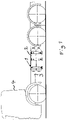
- Fig 1 illustrates very schematically a possible use of an arrangement 1 according to the present invention for fixation of objects in the form of gas fuel tanks 2 to the chassis 3 of a motor vehicle 4 in the form of a truck. It is pointed out that a number of components of the vehicle have been omitted, since they have nothing to do with the present invention directed to said arrangement for fixation of objects.
- FIG. 2 The general structure of an arrangement of the type to which the arrangement of the present invention belongs is illustrated in fig 2 .
- This arrangement comprises a strap 5 configured to have opposite ends 6, 7 thereof connected to a supporting body in the form of an L-shaped bracket 8 to be secured to the chassis of a vehicle.
- the strap has two parts 9, 10 interconnected by an assembly 11 comprising a couple of two pins 12, 13, secured to an end of the respective strap part by being received in a strap end loop, spaced apart and extending transversely to the longitudinal extension of the strap and in parallel with the strap and a member 14, here a bolt, creating an interconnection of the pins and configured to be acted upon for tightening the strap around an object embraced by the strap and the bracket by reducing the distance separating the pins 12, 13.
- the two pins 12, 13 are both provided with a slotted through-hole 15 with a diameter exceding the diameter of a bolt 16 forming a said member and extending through the through-holes of both pins.
- the bolt 16 has a head 17 received in a cylindrical seat 18 formed by the slotted through-hole in a first 12 of the pins by means of a first nut 19 with a through-hole of a diameter exceding the diameter of the bolt and has a second nut 20 received in a cylindrical seat formed by the slotted through-hole in a second 13 of the pins and provided with an internal thread engaging with an external thread of the bolt.
- the first and the second nuts 19, 20 have cylindrical profiles corresponding to the profiles of the cylindrical seats in the respective pin so as to make these nuts turning in said seats by tilting of the pins without applying bending forces upon the bolt as shown in fig 5 .
- a strap when applied between the two strap parts 9, 10 of a strap shown in fig 2 such a strap may be tightened by turning the bolt 16 so as to reduce the distance between the two pins 12, 13. Bending forces applied to the strap by abrupt speed changes of the vehicle will result in a bending of the strap in a plane in parallel with large flat surfaces of the strap and by that tilting of the pins as shown in fig 5 without application of any bending forces upon the bolt 16, so that the interconnection of the two pins is provided with a hinge.
- Figs 6 and 7 illustrate an assembly 11' of an arrangement according to a second embodiment of the invention different from the one shown in fig 5 by the fact that the two pins 12', 13' have a portion 21 with an enlarged cross-section around the through-hole forming a seat 22. It is shown how the first 19' and second 20' nuts have profiles corresponding to the profiles of the seats on the respective pin so as to make the nuts turning in/on said seats by tilting of the pins 12', 13' without applying bending forces upon the bolt 16'. Fig 7 shows how the pins have been tilted with respect to each other without for that sake applying any bending force upon the bolt 16'.
- Figs 8-10 illustrate an assembly 11" being a part of an arrangement according to a third embodiment of the invention differing from the one shown in figs 3-5 by having a bolt 16" without any head and having a thread at each end engaging the internal thread of a nut so as to reduce the distance between the two pins 12", 13" by turning the bolt. Furthermore, the bolt 16" is divided into two parts 16a, 16b interconnected by a hinge 23 enabling these parts to pivot with respect to each other when the pins 12", 13" tilt with respect to each other as shown in fig 10 .
- the arrangement may as already mentioned have a plurality of said assemblies, and the pins of the assemblies have not to have a circular cross-section but any elongated element with any cross-section is conceivable, although a circular or elliptical cross-section may be preferred for facilitating turning of the pin in a strap loop receiving the pin.
Landscapes
- Engineering & Computer Science (AREA)
- Life Sciences & Earth Sciences (AREA)
- Sustainable Development (AREA)
- Sustainable Energy (AREA)
- Chemical & Material Sciences (AREA)
- Combustion & Propulsion (AREA)
- Transportation (AREA)
- Mechanical Engineering (AREA)
- Clamps And Clips (AREA)
- Buckles (AREA)
- Cooling, Air Intake And Gas Exhaust, And Fuel Tank Arrangements In Propulsion Units (AREA)
Description
- The present invention relates to an arrangement for fixation of one or more objects comprising
- a strap configured to have opposite ends thereof connected to a supporting body to which said objects are to be fixed by tightening the strap therearound, and
- a strap tightening assembly comprising a couple of two pins spaced apart and extending transversely to the longitudinal extension of the strap and in parallel with the strap and a member creating an interconnection of the pins and configured to be acted upon for tightening the strap around said objects by reducing the distance separating the pins.
- Such arrangements may for example be used to fixate objects to a chassis fixed part of a motor vehicle, especially a heavy motor vehicle, such as a truck, a lorry or a bus, which is the reason for below discussing the invention and the problem to be solved thereby for such a use for illuminating the invention but accordingly not restrict it to that application. Thus, opposite ends of the strap may be connected to any supporting body and fix any object thereto by tightening of the strap therearound.
- Furthermore, the strap may have more than one part forming the strap by being connected in series between said opposite ends of the strap.
- An arrangement of the type defined above is known through for example
CN 103909822 . A known such arrangement is used to fixate fuel storage tanks, for example containing diesel or gas fuel, to L-shaped brackets secured to the chassis of motor vehicles in the form of trucks. In such a known arrangement the strap has two parts interconnected by a said assembly for tightening the strap by actuating a said member in the form of a bolt interconnecting the two pins of the two strap parts. The bolt extends through through-holes in the two pins, in which one of the pins has a through-hole with a diameter exceeding the diameter of the bolt and the other has a through-hole provided with an internal thread with which the thread of the bolt engages. The bolt may not be tightened so that the pins come to bear against each other so as to be able to ensure a required tightening and jamming force of the strap in spite of tolerances existing. It is of course crucial to prevent that the package of fuel storage tanks may not come loose from the brackets, since that would constitute a danger to the environment as a consequence of the inflammable content and the high pressure thereof in the case of gas fuel. - However, would the speed of the truck in the driving direction change rapidly, for example owing to a collision, the package of fuel storage tanks will owing to inertia be thrown away and the bracket and the strap will then be twisted for keeping said package fixed to the bracket. This would then result in a bending force applied to the bolt since the bolt has not been tightened to make the pins bearing against each other, and the bolt is not made to withstand the bending thereof then resulting, so that there is an imminent risk of a breaking of the bolt so that the fuel storage tank package will come loose from the truck.
- The object of the present invention is to provide an arrangement of the type defined in the introduction being improved in at least some aspect with respect to such arrangements already known.
- This object is according to the invention obtained by providing such an arrangement with the features listed in the characterizing part of appended
patent claim 1. - The hinge in the interconnection of the pins allowing the pins to tilt with respect to each other in a plane in parallel with large flat surfaces of the strap and the provision of the strap with a stiffness enabling a bending thereof in the plane of said tilting to a degree corresponding to said tilting enables a said tilting of the pins with respect to each other without applying bending forces on said member, such as a bolt, creating said interconnection, so that this member will not be bent and broken even if high forces are applied on the strap and by that on said assembly, such as in the case of fixation of objects to a chassis fixed part of a motor vehicle through heavy accelerations or retardations of the vehicle.
- According to an embodiment of the invention the strap comprises at least two parts interconnected by a said assembly by each having one pin of a said couple at an end of the strap part adjacent to the end of the other strap part and a said member interconnecting these pins. Such a location of the assembly may be advantageous for providing desired access to act upon said member for tightening the strap around an object.
- According to another embodiment of the invention the arrangement comprises a said assembly at at least one of the ends of the strap connected to said supporting body with said strap end provided with one pin of a said couple and the other pin of the couple connected to the supporting body and a said member interconnecting these two pins. Such a location of a said assembly may in some applications of an arrangement according to the invention be preferred, and it is also possible to combine such a location with a location of another assembly between two strap parts and/or having a said assembly at each end of the strap for enabling tightening of the strap by acting on a said member at more than one location.
- According to another embodiment of the invention said member of said assembly comprises a bolt. A bolt, which is here to be interpreted as an elongated element with an external thread and accordingly comprising among others a conventional screw, is a suitable choice for a member used to tightening the strap by reducing the distance separating the pins when acted upon.
- According to another embodiment of the invention the two pins of a said couple are provided both with a through-hole with a diameter exceeding the diameter of the bolt, the bolt extends through the through-holes of both pins and has a head thereof received in a seat formed around the through-hole in a first of said pins by means of a first nut with a through-hole of a diameter exceeding the diameter of the bolt and has a second nut received in a seat formed around the through-hole in a second of the pins and provided with an internal thread engaging with an external thread of the bolt, and the first and second nuts have profiles adapted to the profiles of the seats of the respective pin so as to make said nuts turning in said seats by tilting of said pins without applying bending forces upon said bolt. This constitutes a simple and reliable way of providing said assembly with a hinge in the interconnection of the pins.
- According to another embodiment of the invention constituting a further development of the embodiment last mentioned said through-holes are slotted, said seats are cylindrical and formed by the slotted through-holes, and the first and second nuts have profiles adapted to the profiles of the seats of the respective pin so as to make said nuts turning in said seats by tilting of said pins without applying bending forces upon said bolt. Such a design of the bolt with nuts with cylindrical seats will then also provide a steady holder-on for tightening the bolt.
- According to another embodiment of the invention the two pins have a convex shape by an enlarged cross-section around said through-holes forming said seats, and the first and second nuts have profiles adapted to the profiles of said seats on the respective pin so as to make said nuts turning in said seats by tilting of said pins without applying bending forces upon said bolt. This constitutes another possible simple and reliable way of realising a hinge in the interconnection of the pins of said assembly.
- According to another embodiment of the invention the arrangement is configured to have said strap connected to a supporting member in the form of a vehicle chassis fixed part, and the arrangement may then have a strap connected to a supporting body in the form of an L-shaped bracket secured to the chassis of a vehicle. Such an arrangement is suitable to be used to fixate an object to a vehicle, such as a fuel tank to a motor vehicle, especially a heavy motor vehicle, such as a truck or a bus.
- According to another embodiment of the invention the arrangement is configured to fixate elongated gas storage tanks to the chassis of a vehicle.
- The invention also relates to a use of an arrangement according to the invention to fixate one or more objects to a vehicle chassis fixed part, and especially a fuel tank to a motor vehicle. The invention also relates to a motor vehicle, especially a heavy motor vehicle, such as a truck or a bus, which is provided with at least one arrangement for fixation of at least one object to a chassis fixed part of the vehicle. The advantages of such a use and motor vehicle appear clearly from the above discussion of an arrangement according to the invention and embodiments thereof.
- Other advantageous features as well as advantages of the present invention appear from the description following below.
- With reference to the appended drawings, below follows a specific description of embodiments of the invention cited as examples.
- In the drawings:
- Fig 1
- is a schematic view illustrating how an arrangement according to the present invention may be used for fixation of gas fuel tanks to a chassis fixed part of a heavy motor vehicle in the form of a truck,
- Fig 2
- is a perspective view of an arrangement of the type to which the present invention is directed,
- Fig 3
- is a perspective view of a pin of an assembly of an arrangement according to a first embodiment of the invention,
- Figs 4 and 5
- are views illustrating a said assembly of an arrangement according to the first embodiment of the invention,
- Figs 6 and 7
- are views illustrating an assembly of an arrangement according to a second embodiment of the invention, and
- Figs 8-10
- are views illustrating an assembly of an arrangement according to a third embodiment of the invention.
-
Fig 1 illustrates very schematically a possible use of anarrangement 1 according to the present invention for fixation of objects in the form of gas fuel tanks 2 to the chassis 3 of a motor vehicle 4 in the form of a truck. It is pointed out that a number of components of the vehicle have been omitted, since they have nothing to do with the present invention directed to said arrangement for fixation of objects. - The general structure of an arrangement of the type to which the arrangement of the present invention belongs is illustrated in
fig 2 . This arrangement comprises astrap 5 configured to have opposite ends 6, 7 thereof connected to a supporting body in the form of an L-shaped bracket 8 to be secured to the chassis of a vehicle. The strap has twoparts 9, 10 interconnected by anassembly 11 comprising a couple of twopins member 14, here a bolt, creating an interconnection of the pins and configured to be acted upon for tightening the strap around an object embraced by the strap and the bracket by reducing the distance separating thepins - The design of an assembly of an arrangement according to a first embodiment of the invention will now be described while making reference to
figs 3-5 . The twopins hole 15 with a diameter exceding the diameter of abolt 16 forming a said member and extending through the through-holes of both pins. Thebolt 16 has ahead 17 received in acylindrical seat 18 formed by the slotted through-hole in a first 12 of the pins by means of afirst nut 19 with a through-hole of a diameter exceding the diameter of the bolt and has asecond nut 20 received in a cylindrical seat formed by the slotted through-hole in asecond 13 of the pins and provided with an internal thread engaging with an external thread of the bolt. The first and thesecond nuts fig 5 . Thus, when applied between the twostrap parts 9, 10 of a strap shown infig 2 such a strap may be tightened by turning thebolt 16 so as to reduce the distance between the twopins fig 5 without application of any bending forces upon thebolt 16, so that the interconnection of the two pins is provided with a hinge. -
Figs 6 and 7 illustrate an assembly 11' of an arrangement according to a second embodiment of the invention different from the one shown infig 5 by the fact that the two pins 12', 13' have aportion 21 with an enlarged cross-section around the through-hole forming aseat 22. It is shown how the first 19' and second 20' nuts have profiles corresponding to the profiles of the seats on the respective pin so as to make the nuts turning in/on said seats by tilting of the pins 12', 13' without applying bending forces upon the bolt 16'.Fig 7 shows how the pins have been tilted with respect to each other without for that sake applying any bending force upon the bolt 16'. -
Figs 8-10 illustrate anassembly 11" being a part of an arrangement according to a third embodiment of the invention differing from the one shown infigs 3-5 by having abolt 16" without any head and having a thread at each end engaging the internal thread of a nut so as to reduce the distance between the twopins 12", 13" by turning the bolt. Furthermore, thebolt 16" is divided into twoparts hinge 23 enabling these parts to pivot with respect to each other when thepins 12", 13" tilt with respect to each other as shown infig 10 . - The invention is of course in no way restricted to the embodiments described above, since many possibilities for modifications thereof are likely to be obvious to one skilled in the art without having to deviate from the scope of invention defined in the appended claims.
- The arrangement may as already mentioned have a plurality of said assemblies, and the pins of the assemblies have not to have a circular cross-section but any elongated element with any cross-section is conceivable, although a circular or elliptical cross-section may be preferred for facilitating turning of the pin in a strap loop receiving the pin.
Claims (13)
- An arrangement for fixation of one or more objects (2) comprising• a strap (5) configured to have opposite ends (6, 7) thereof connected to a supporting body (3, 8) to which said objects are to be fixed by tightening the strap therearound, and• a strap tightening assembly (11, 11', 11") comprising a couple of two pins (12, 13, 12', 13', 12", 13") spaced apart and extending transversely to the longitudinal extension of the strap (5) and in parallel with large flat surfaces of the strap and a member (16, 16', 16") creating an interconnection of the pins and configured to be acted upon for tightening the strap around said objects by reducing the distance separating the pins,characterized in that said assembly (11, 11', 11") comprises a hinge in said interconnection allowing said pins (12, 13, 12', 13', 12", 13") to tilt with respect to each other in a plane in parallel with large flat surfaces of the strap (5).
- An arrangement according to claim 1, characterized in that said strap (5) comprises at least two parts (9, 10) interconnected by a said assembly (11, 11', 11") by each having one pin of a said couple at an end of the strap part adjacent to the end of the other strap part and a said member (16, 16', 16") interconnecting these pins.
- An arrangement according to claim 1 or 2, characterized in that it comprises a said assembly (11, 11', 11") at at least one of the ends of the strap connected to said supporting body (3, 8) with said strap end (6, 7) provided with one pin of a said couple and the other pin of the couple connected to the supporting body and a said member (16, 16', 16") interconnecting these two pins.
- An arrangement according to any of the preceding claims, characterized in that said member of said assembly (11, 11', 11") comprises a bolt (16, 16', 16").
- An arrangement according to claim 4, characterized in that the two pins (12, 13, 12', 13') of a said couple are provided both with a through-hole (15) with a diameter exceeding the diameter of the bolt (16, 16'), that the bolt extends through the through-holes of both pins and has a head (17, 17') thereof received in a seat formed around the through-hole (15) in a first (12, 12') of said pins by means of a first nut (19, 19') with a through-hole of a diameter exceeding the diameter of the bolt and has a second nut (20, 20') received in a seat formed around the through-hole in a second (13, 13') of the pins and provided with an internal thread engaging with an external thread of the bolt, and that the first (19, 19') and second nuts (20, 20') have profiles adapted to the profiles of the seats of the respective pin so as to make said nuts turning in said seats by tilting of said pins without applying bending forces upon said bolt.
- An arrangement according to claim 5, characterized in that said through-holes (15) are slotted, that said seats (18) are cylindrical and formed by the slotted through-holes, and that the first (19) and second (20) nuts have profiles adapted to the profiles of the seats of the respective pin (12, 13) so as to make said nuts turning in said seats by tilting of said pins without applying bending forces upon said bolt (16).
- An arrangement according to claim 5, characterized in that the two pins (12', 13') have a convex shape by an enlarged cross-section around said through-holes forming said seats (22), and that the first (19') and second (20') nuts have profiles adapted to the profiles of said seats on the respective pin so as to make said nuts turning in said seats by tilting of said pins without applying bending forces upon said bolt (16').
- An arrangement according to any of the preceding claims, characterized in that it is configured to have said strap (5) connected to a supporting body (3) in the form of a vehicle chassis fixed part.
- An arrangement according to claim 8, characterized in that it is configured to have said strap (5) connected to a supporting body in the form of an L-shaped bracket (8) secured to the chassis (3) of a vehicle (4).
- An arrangement according to claim 8 or 9, characterized in that it is configured to fixate a fuel tank (2) to a motor vehicle (4), especially a heavy motor vehicle, such as a truck or a bus.
- An arrangement according to claim 10, characterized in that it is configured to fixate elongated gas storage tanks (2) to the chassis (3) of a vehicle (4).
- Use of an arrangement according to any of the preceeding claims to fixate one or more objects (2) to a vehicle chassis (3) fixed part.
- A motor vehicle, especially a heavy motor vehicle, such as a truck or a bus, characterized in that it is provided with at least one arrangement (1) according to any of claims 1-11 for fixation of at least one object to a chassis fixed part of the vehicle.
Applications Claiming Priority (2)
| Application Number | Priority Date | Filing Date | Title |
|---|---|---|---|
| SE1651076A SE540081C2 (en) | 2016-07-21 | 2016-07-21 | A fixation arrangement |
| PCT/SE2017/050640 WO2018017006A1 (en) | 2016-07-21 | 2017-06-15 | A fixation arrangement |
Publications (3)
| Publication Number | Publication Date |
|---|---|
| EP3487722A1 EP3487722A1 (en) | 2019-05-29 |
| EP3487722A4 EP3487722A4 (en) | 2020-05-06 |
| EP3487722B1 true EP3487722B1 (en) | 2022-06-08 |
Family
ID=60993312
Family Applications (1)
| Application Number | Title | Priority Date | Filing Date |
|---|---|---|---|
| EP17831437.3A Active EP3487722B1 (en) | 2016-07-21 | 2017-06-15 | A fixation arrangement |
Country Status (5)
| Country | Link |
|---|---|
| EP (1) | EP3487722B1 (en) |
| KR (1) | KR102185176B1 (en) |
| CN (1) | CN109476231B (en) |
| SE (1) | SE540081C2 (en) |
| WO (1) | WO2018017006A1 (en) |
Cited By (1)
| Publication number | Priority date | Publication date | Assignee | Title |
|---|---|---|---|---|
| WO2024056841A3 (en) * | 2022-09-16 | 2024-07-18 | Oetiker Schweiz Ag | Fixing structure with damping trunnion and mounting assembly |
Families Citing this family (4)
| Publication number | Priority date | Publication date | Assignee | Title |
|---|---|---|---|---|
| DE102016015645A1 (en) * | 2016-12-30 | 2018-07-05 | Man Truck & Bus Ag | Tensioning strap, in particular for fastening an object to a vehicle |
| DE102017002885A1 (en) * | 2017-03-25 | 2018-09-27 | Man Truck & Bus Ag | Fastening device for a strap |
| JP7505455B2 (en) * | 2021-06-30 | 2024-06-25 | トヨタ自動車株式会社 | Tank Retention Device |
| DE102024101669A1 (en) * | 2024-01-22 | 2025-07-24 | Norma Germany Gmbh | Securing system and method for securing a fluid container |
Family Cites Families (10)
| Publication number | Priority date | Publication date | Assignee | Title |
|---|---|---|---|---|
| US2941273A (en) * | 1958-08-18 | 1960-06-21 | Specialty Products Corp | Clamp |
| KR100453655B1 (en) * | 2001-12-27 | 2004-10-20 | 현대자동차주식회사 | Strap mounting structure of fuel tank for truck |
| SE527073C2 (en) * | 2005-04-12 | 2005-12-20 | Levi Peterson Ind Ab | Strip for securing automotive part to vehicle chassis, has flanged ends with screw holes and reinforcing ribs |
| FR2927132B1 (en) * | 2008-02-05 | 2010-03-26 | Caillau Ets | FIXING DEVICE HAVING A SUPPORT PART AND A BELT |
| DE102009042596B4 (en) * | 2009-09-23 | 2013-04-04 | Hydac Accessories Gmbh | Joint Band Clamp |
| DE102012004319A1 (en) * | 2012-03-03 | 2013-09-05 | Volkswagen Aktiengesellschaft | Device for fastening of tension strap of gas tank used in vehicle, has plate spring and tension strap that are operatively connected, and includes one fastening element that is arranged on rod in accordance with one of the bolts |
| FR2988041B1 (en) * | 2012-03-15 | 2014-02-28 | Renault Sas | SYSTEM FOR LOCKING / UNLOCKING AN OBJECT UNDER A RECOVERY AND SUPPORT CROCHET STRUCTURE |
| DE102012023160A1 (en) * | 2012-11-28 | 2013-08-01 | Daimler Ag | Load distribution element for band e.g. lorry, has opening for receiving bolt, where load distribution element is partly loopable from loop of clamping band, and support surface delimited by collar is arranged at load distribution element |
| CN203162534U (en) * | 2012-12-19 | 2013-08-28 | 陕西重型汽车有限公司 | Automobile LNG (liquefied natural gas) gas bottle fastening mechanism |
| CN103909822A (en) * | 2012-12-31 | 2014-07-09 | 上海奥林汽车配件有限公司 | Fixing device for automobile liquid storage steel cylinder |
-
2016
- 2016-07-21 SE SE1651076A patent/SE540081C2/en unknown
-
2017
- 2017-06-15 EP EP17831437.3A patent/EP3487722B1/en active Active
- 2017-06-15 KR KR1020197004137A patent/KR102185176B1/en active Active
- 2017-06-15 CN CN201780043575.3A patent/CN109476231B/en active Active
- 2017-06-15 WO PCT/SE2017/050640 patent/WO2018017006A1/en not_active Ceased
Cited By (1)
| Publication number | Priority date | Publication date | Assignee | Title |
|---|---|---|---|---|
| WO2024056841A3 (en) * | 2022-09-16 | 2024-07-18 | Oetiker Schweiz Ag | Fixing structure with damping trunnion and mounting assembly |
Also Published As
| Publication number | Publication date |
|---|---|
| CN109476231A (en) | 2019-03-15 |
| SE1651076A1 (en) | 2018-01-22 |
| EP3487722A4 (en) | 2020-05-06 |
| SE540081C2 (en) | 2018-03-20 |
| BR112018076753A2 (en) | 2019-03-26 |
| WO2018017006A1 (en) | 2018-01-25 |
| KR102185176B1 (en) | 2020-12-01 |
| CN109476231B (en) | 2021-11-23 |
| EP3487722A1 (en) | 2019-05-29 |
| KR20190026897A (en) | 2019-03-13 |
Similar Documents
| Publication | Publication Date | Title |
|---|---|---|
| EP2558732B1 (en) | Suspension device for vehicle | |
| US9242542B2 (en) | System for reducing engine roll | |
| EP2682616A1 (en) | Bracket with nut | |
| KR102185176B1 (en) | Fixed structure | |
| US20090266634A1 (en) | Vehicular radiator supporting apparatus | |
| EP2684721A2 (en) | Onboard equipment fixing structure | |
| US10933729B2 (en) | Methods and systems for a powertrain mount assembly | |
| EP1380462B1 (en) | Fastening device for container | |
| US12325297B2 (en) | Mounting structure for fuel storage device of vehicle | |
| US10752193B2 (en) | Vehicle incorporating a deformable front frame structure | |
| CN104071233A (en) | Structure for steering support member | |
| US8968028B2 (en) | Connection structure provided between a battery terminal and a fuse unit | |
| JP5961894B2 (en) | Vehicle door hinge | |
| US12384310B2 (en) | Instrument panel structure | |
| EP2711223A1 (en) | Power unit mounting apparatus | |
| EP2323871B1 (en) | Airbag system | |
| CN110300695B (en) | Body arrangement of a vehicle, in particular of a motor vehicle | |
| JP2005014832A (en) | Installing structure of impact absorbing steering device | |
| KR102668903B1 (en) | Noise deadening baffles for automotive tanks | |
| CN215794030U (en) | A lightweight tail beam and its frame mounting structure | |
| US20170113505A1 (en) | Vehicle body structure having shock absorber mounting structure | |
| KR102041147B1 (en) | Tension link | |
| EP1459002B1 (en) | Support device to be used for attaching pipes and cables to a vehicle, comprising a console designed with a convex envelope surface | |
| US8979118B2 (en) | Inflator fastening | |
| JP2024129419A (en) | Bus bar |
Legal Events
| Date | Code | Title | Description |
|---|---|---|---|
| STAA | Information on the status of an ep patent application or granted ep patent |
Free format text: STATUS: THE INTERNATIONAL PUBLICATION HAS BEEN MADE |
|
| PUAI | Public reference made under article 153(3) epc to a published international application that has entered the european phase |
Free format text: ORIGINAL CODE: 0009012 |
|
| STAA | Information on the status of an ep patent application or granted ep patent |
Free format text: STATUS: REQUEST FOR EXAMINATION WAS MADE |
|
| 17P | Request for examination filed |
Effective date: 20190221 |
|
| AK | Designated contracting states |
Kind code of ref document: A1 Designated state(s): AL AT BE BG CH CY CZ DE DK EE ES FI FR GB GR HR HU IE IS IT LI LT LU LV MC MK MT NL NO PL PT RO RS SE SI SK SM TR |
|
| AX | Request for extension of the european patent |
Extension state: BA ME |
|
| DAV | Request for validation of the european patent (deleted) | ||
| DAX | Request for extension of the european patent (deleted) | ||
| A4 | Supplementary search report drawn up and despatched |
Effective date: 20200402 |
|
| RIC1 | Information provided on ipc code assigned before grant |
Ipc: B60K 15/067 20060101AFI20200328BHEP Ipc: B60K 15/07 20060101ALI20200328BHEP |
|
| RAP3 | Party data changed (applicant data changed or rights of an application transferred) |
Owner name: SCANIA CV AB |
|
| GRAP | Despatch of communication of intention to grant a patent |
Free format text: ORIGINAL CODE: EPIDOSNIGR1 |
|
| STAA | Information on the status of an ep patent application or granted ep patent |
Free format text: STATUS: GRANT OF PATENT IS INTENDED |
|
| INTG | Intention to grant announced |
Effective date: 20220120 |
|
| GRAS | Grant fee paid |
Free format text: ORIGINAL CODE: EPIDOSNIGR3 |
|
| GRAA | (expected) grant |
Free format text: ORIGINAL CODE: 0009210 |
|
| STAA | Information on the status of an ep patent application or granted ep patent |
Free format text: STATUS: THE PATENT HAS BEEN GRANTED |
|
| AK | Designated contracting states |
Kind code of ref document: B1 Designated state(s): AL AT BE BG CH CY CZ DE DK EE ES FI FR GB GR HR HU IE IS IT LI LT LU LV MC MK MT NL NO PL PT RO RS SE SI SK SM TR |
|
| REG | Reference to a national code |
Ref country code: AT Ref legal event code: REF Ref document number: 1496697 Country of ref document: AT Kind code of ref document: T Effective date: 20220615 Ref country code: CH Ref legal event code: EP |
|
| REG | Reference to a national code |
Ref country code: DE Ref legal event code: R096 Ref document number: 602017058371 Country of ref document: DE |
|
| REG | Reference to a national code |
Ref country code: IE Ref legal event code: FG4D |
|
| REG | Reference to a national code |
Ref country code: SE Ref legal event code: TRGR |
|
| REG | Reference to a national code |
Ref country code: LT Ref legal event code: MG9D |
|
| REG | Reference to a national code |
Ref country code: NL Ref legal event code: MP Effective date: 20220608 |
|
| PG25 | Lapsed in a contracting state [announced via postgrant information from national office to epo] |
Ref country code: NO Free format text: LAPSE BECAUSE OF FAILURE TO SUBMIT A TRANSLATION OF THE DESCRIPTION OR TO PAY THE FEE WITHIN THE PRESCRIBED TIME-LIMIT Effective date: 20220908 Ref country code: LT Free format text: LAPSE BECAUSE OF FAILURE TO SUBMIT A TRANSLATION OF THE DESCRIPTION OR TO PAY THE FEE WITHIN THE PRESCRIBED TIME-LIMIT Effective date: 20220608 Ref country code: HR Free format text: LAPSE BECAUSE OF FAILURE TO SUBMIT A TRANSLATION OF THE DESCRIPTION OR TO PAY THE FEE WITHIN THE PRESCRIBED TIME-LIMIT Effective date: 20220608 Ref country code: GR Free format text: LAPSE BECAUSE OF FAILURE TO SUBMIT A TRANSLATION OF THE DESCRIPTION OR TO PAY THE FEE WITHIN THE PRESCRIBED TIME-LIMIT Effective date: 20220909 Ref country code: FI Free format text: LAPSE BECAUSE OF FAILURE TO SUBMIT A TRANSLATION OF THE DESCRIPTION OR TO PAY THE FEE WITHIN THE PRESCRIBED TIME-LIMIT Effective date: 20220608 Ref country code: ES Free format text: LAPSE BECAUSE OF FAILURE TO SUBMIT A TRANSLATION OF THE DESCRIPTION OR TO PAY THE FEE WITHIN THE PRESCRIBED TIME-LIMIT Effective date: 20220608 Ref country code: BG Free format text: LAPSE BECAUSE OF FAILURE TO SUBMIT A TRANSLATION OF THE DESCRIPTION OR TO PAY THE FEE WITHIN THE PRESCRIBED TIME-LIMIT Effective date: 20220908 |
|
| REG | Reference to a national code |
Ref country code: AT Ref legal event code: MK05 Ref document number: 1496697 Country of ref document: AT Kind code of ref document: T Effective date: 20220608 |
|
| PG25 | Lapsed in a contracting state [announced via postgrant information from national office to epo] |
Ref country code: RS Free format text: LAPSE BECAUSE OF FAILURE TO SUBMIT A TRANSLATION OF THE DESCRIPTION OR TO PAY THE FEE WITHIN THE PRESCRIBED TIME-LIMIT Effective date: 20220608 Ref country code: LV Free format text: LAPSE BECAUSE OF FAILURE TO SUBMIT A TRANSLATION OF THE DESCRIPTION OR TO PAY THE FEE WITHIN THE PRESCRIBED TIME-LIMIT Effective date: 20220608 |
|
| PG25 | Lapsed in a contracting state [announced via postgrant information from national office to epo] |
Ref country code: NL Free format text: LAPSE BECAUSE OF FAILURE TO SUBMIT A TRANSLATION OF THE DESCRIPTION OR TO PAY THE FEE WITHIN THE PRESCRIBED TIME-LIMIT Effective date: 20220608 |
|
| PG25 | Lapsed in a contracting state [announced via postgrant information from national office to epo] |
Ref country code: SM Free format text: LAPSE BECAUSE OF FAILURE TO SUBMIT A TRANSLATION OF THE DESCRIPTION OR TO PAY THE FEE WITHIN THE PRESCRIBED TIME-LIMIT Effective date: 20220608 Ref country code: SK Free format text: LAPSE BECAUSE OF FAILURE TO SUBMIT A TRANSLATION OF THE DESCRIPTION OR TO PAY THE FEE WITHIN THE PRESCRIBED TIME-LIMIT Effective date: 20220608 Ref country code: RO Free format text: LAPSE BECAUSE OF FAILURE TO SUBMIT A TRANSLATION OF THE DESCRIPTION OR TO PAY THE FEE WITHIN THE PRESCRIBED TIME-LIMIT Effective date: 20220608 Ref country code: PT Free format text: LAPSE BECAUSE OF FAILURE TO SUBMIT A TRANSLATION OF THE DESCRIPTION OR TO PAY THE FEE WITHIN THE PRESCRIBED TIME-LIMIT Effective date: 20221010 Ref country code: EE Free format text: LAPSE BECAUSE OF FAILURE TO SUBMIT A TRANSLATION OF THE DESCRIPTION OR TO PAY THE FEE WITHIN THE PRESCRIBED TIME-LIMIT Effective date: 20220608 Ref country code: CZ Free format text: LAPSE BECAUSE OF FAILURE TO SUBMIT A TRANSLATION OF THE DESCRIPTION OR TO PAY THE FEE WITHIN THE PRESCRIBED TIME-LIMIT Effective date: 20220608 Ref country code: AT Free format text: LAPSE BECAUSE OF FAILURE TO SUBMIT A TRANSLATION OF THE DESCRIPTION OR TO PAY THE FEE WITHIN THE PRESCRIBED TIME-LIMIT Effective date: 20220608 |
|
| REG | Reference to a national code |
Ref country code: CH Ref legal event code: PL |
|
| PG25 | Lapsed in a contracting state [announced via postgrant information from national office to epo] |
Ref country code: PL Free format text: LAPSE BECAUSE OF FAILURE TO SUBMIT A TRANSLATION OF THE DESCRIPTION OR TO PAY THE FEE WITHIN THE PRESCRIBED TIME-LIMIT Effective date: 20220608 Ref country code: IS Free format text: LAPSE BECAUSE OF FAILURE TO SUBMIT A TRANSLATION OF THE DESCRIPTION OR TO PAY THE FEE WITHIN THE PRESCRIBED TIME-LIMIT Effective date: 20221008 |
|
| REG | Reference to a national code |
Ref country code: DE Ref legal event code: R097 Ref document number: 602017058371 Country of ref document: DE |
|
| PG25 | Lapsed in a contracting state [announced via postgrant information from national office to epo] |
Ref country code: MC Free format text: LAPSE BECAUSE OF FAILURE TO SUBMIT A TRANSLATION OF THE DESCRIPTION OR TO PAY THE FEE WITHIN THE PRESCRIBED TIME-LIMIT Effective date: 20220608 Ref country code: AL Free format text: LAPSE BECAUSE OF FAILURE TO SUBMIT A TRANSLATION OF THE DESCRIPTION OR TO PAY THE FEE WITHIN THE PRESCRIBED TIME-LIMIT Effective date: 20220608 |
|
| PLBE | No opposition filed within time limit |
Free format text: ORIGINAL CODE: 0009261 |
|
| STAA | Information on the status of an ep patent application or granted ep patent |
Free format text: STATUS: NO OPPOSITION FILED WITHIN TIME LIMIT |
|
| PG25 | Lapsed in a contracting state [announced via postgrant information from national office to epo] |
Ref country code: LU Free format text: LAPSE BECAUSE OF NON-PAYMENT OF DUE FEES Effective date: 20220615 Ref country code: LI Free format text: LAPSE BECAUSE OF NON-PAYMENT OF DUE FEES Effective date: 20220630 Ref country code: IE Free format text: LAPSE BECAUSE OF NON-PAYMENT OF DUE FEES Effective date: 20220615 Ref country code: DK Free format text: LAPSE BECAUSE OF FAILURE TO SUBMIT A TRANSLATION OF THE DESCRIPTION OR TO PAY THE FEE WITHIN THE PRESCRIBED TIME-LIMIT Effective date: 20220608 Ref country code: CH Free format text: LAPSE BECAUSE OF NON-PAYMENT OF DUE FEES Effective date: 20220630 |
|
| 26N | No opposition filed |
Effective date: 20230310 |
|
| PG25 | Lapsed in a contracting state [announced via postgrant information from national office to epo] |
Ref country code: SI Free format text: LAPSE BECAUSE OF FAILURE TO SUBMIT A TRANSLATION OF THE DESCRIPTION OR TO PAY THE FEE WITHIN THE PRESCRIBED TIME-LIMIT Effective date: 20220608 |
|
| P01 | Opt-out of the competence of the unified patent court (upc) registered |
Effective date: 20230518 |
|
| PG25 | Lapsed in a contracting state [announced via postgrant information from national office to epo] |
Ref country code: IT Free format text: LAPSE BECAUSE OF FAILURE TO SUBMIT A TRANSLATION OF THE DESCRIPTION OR TO PAY THE FEE WITHIN THE PRESCRIBED TIME-LIMIT Effective date: 20220608 |
|
| PG25 | Lapsed in a contracting state [announced via postgrant information from national office to epo] |
Ref country code: HU Free format text: LAPSE BECAUSE OF FAILURE TO SUBMIT A TRANSLATION OF THE DESCRIPTION OR TO PAY THE FEE WITHIN THE PRESCRIBED TIME-LIMIT; INVALID AB INITIO Effective date: 20170615 |
|
| PG25 | Lapsed in a contracting state [announced via postgrant information from national office to epo] |
Ref country code: MK Free format text: LAPSE BECAUSE OF FAILURE TO SUBMIT A TRANSLATION OF THE DESCRIPTION OR TO PAY THE FEE WITHIN THE PRESCRIBED TIME-LIMIT Effective date: 20220608 Ref country code: CY Free format text: LAPSE BECAUSE OF FAILURE TO SUBMIT A TRANSLATION OF THE DESCRIPTION OR TO PAY THE FEE WITHIN THE PRESCRIBED TIME-LIMIT Effective date: 20220608 |
|
| PG25 | Lapsed in a contracting state [announced via postgrant information from national office to epo] |
Ref country code: MT Free format text: LAPSE BECAUSE OF FAILURE TO SUBMIT A TRANSLATION OF THE DESCRIPTION OR TO PAY THE FEE WITHIN THE PRESCRIBED TIME-LIMIT Effective date: 20220608 |
|
| PG25 | Lapsed in a contracting state [announced via postgrant information from national office to epo] |
Ref country code: BG Free format text: LAPSE BECAUSE OF FAILURE TO SUBMIT A TRANSLATION OF THE DESCRIPTION OR TO PAY THE FEE WITHIN THE PRESCRIBED TIME-LIMIT Effective date: 20220608 |
|
| PG25 | Lapsed in a contracting state [announced via postgrant information from national office to epo] |
Ref country code: BG Free format text: LAPSE BECAUSE OF FAILURE TO SUBMIT A TRANSLATION OF THE DESCRIPTION OR TO PAY THE FEE WITHIN THE PRESCRIBED TIME-LIMIT Effective date: 20220608 |
|
| PGFP | Annual fee paid to national office [announced via postgrant information from national office to epo] |
Ref country code: DE Payment date: 20250429 Year of fee payment: 9 |
|
| PGFP | Annual fee paid to national office [announced via postgrant information from national office to epo] |
Ref country code: GB Payment date: 20250501 Year of fee payment: 9 |
|
| PGFP | Annual fee paid to national office [announced via postgrant information from national office to epo] |
Ref country code: BE Payment date: 20250516 Year of fee payment: 9 |
|
| PGFP | Annual fee paid to national office [announced via postgrant information from national office to epo] |
Ref country code: FR Payment date: 20250508 Year of fee payment: 9 |
|
| PGFP | Annual fee paid to national office [announced via postgrant information from national office to epo] |
Ref country code: SE Payment date: 20250429 Year of fee payment: 9 |
|
| PG25 | Lapsed in a contracting state [announced via postgrant information from national office to epo] |
Ref country code: TR Free format text: LAPSE BECAUSE OF FAILURE TO SUBMIT A TRANSLATION OF THE DESCRIPTION OR TO PAY THE FEE WITHIN THE PRESCRIBED TIME-LIMIT Effective date: 20220608 |