EP3487642B1 - Verfahren und vorrichtung zum ermitteln der planheit von bandmaterial und bearbeitungsanlage mit einer solchen vorrichtung - Google Patents
Verfahren und vorrichtung zum ermitteln der planheit von bandmaterial und bearbeitungsanlage mit einer solchen vorrichtung Download PDFInfo
- Publication number
- EP3487642B1 EP3487642B1 EP18721023.2A EP18721023A EP3487642B1 EP 3487642 B1 EP3487642 B1 EP 3487642B1 EP 18721023 A EP18721023 A EP 18721023A EP 3487642 B1 EP3487642 B1 EP 3487642B1
- Authority
- EP
- European Patent Office
- Prior art keywords
- strip material
- projection
- pattern
- strip
- optics
- Prior art date
- Legal status (The legal status is an assumption and is not a legal conclusion. Google has not performed a legal analysis and makes no representation as to the accuracy of the status listed.)
- Active
Links
Images




Classifications
-
- B—PERFORMING OPERATIONS; TRANSPORTING
- B21—MECHANICAL METAL-WORKING WITHOUT ESSENTIALLY REMOVING MATERIAL; PUNCHING METAL
- B21B—ROLLING OF METAL
- B21B38/00—Methods or devices for measuring, detecting or monitoring specially adapted for metal-rolling mills, e.g. position detection, inspection of the product
- B21B38/02—Methods or devices for measuring, detecting or monitoring specially adapted for metal-rolling mills, e.g. position detection, inspection of the product for measuring flatness or profile of strips
-
- G—PHYSICS
- G01—MEASURING; TESTING
- G01B—MEASURING LENGTH, THICKNESS OR SIMILAR LINEAR DIMENSIONS; MEASURING ANGLES; MEASURING AREAS; MEASURING IRREGULARITIES OF SURFACES OR CONTOURS
- G01B11/00—Measuring arrangements characterised by the use of optical techniques
- G01B11/24—Measuring arrangements characterised by the use of optical techniques for measuring contours or curvatures
- G01B11/25—Measuring arrangements characterised by the use of optical techniques for measuring contours or curvatures by projecting a pattern, e.g. one or more lines, moiré fringes on the object
- G01B11/2513—Measuring arrangements characterised by the use of optical techniques for measuring contours or curvatures by projecting a pattern, e.g. one or more lines, moiré fringes on the object with several lines being projected in more than one direction, e.g. grids, patterns
-
- G—PHYSICS
- G01—MEASURING; TESTING
- G01B—MEASURING LENGTH, THICKNESS OR SIMILAR LINEAR DIMENSIONS; MEASURING ANGLES; MEASURING AREAS; MEASURING IRREGULARITIES OF SURFACES OR CONTOURS
- G01B11/00—Measuring arrangements characterised by the use of optical techniques
- G01B11/30—Measuring arrangements characterised by the use of optical techniques for measuring roughness or irregularity of surfaces
- G01B11/306—Measuring arrangements characterised by the use of optical techniques for measuring roughness or irregularity of surfaces for measuring evenness
Definitions
- the invention relates to a method and a device for determining the flatness of a moving strip material.
- the invention further relates to a method and a processing system for processing strip material with such a device.
- a method for determining the flatness of moving strip material comprising the steps of: moving strip material through a strip processing device and measuring the flatness of the processed strip material through a flatness measuring bar.
- the device includes a first source that projects a first interference pattern on the first surface and a second source that projects a second interference pattern on the second surface.
- the device further comprises a first detector that detects the first interference pattern, a second detector that detects the second interference pattern.
- the first detector and the second detector each generate a signal based on the detected interference pattern.
- a processor calculates the variation in the thickness of the object based on the first and second signals.
- the object has two opposite surfaces and, in one embodiment, is a sheet material.
- the Apparatus includes a first projection source to project a first fringe pattern onto the first surface and a second projection source to project a second stripe pattern onto the second surface.
- the stripes of the stripe patterns are parallel to the direction of movement of the plate material.
- the object is designed in the form of a wafer or a CD, which can be accommodated in a rotatable chuck. The stripes are projected onto the wafer perpendicular to a diameter of the wafer.
- a method for measuring the flatness of metal strip in which a line pattern is generated on a strip surface with a projector and is recorded directly by a camera.
- a CCD camera is used as the camera, which is arranged so that there is an angle between the light source of the surface and the camera.
- the measuring arrangement is arranged on a measuring house in front of the reel, the camera being arranged on the measuring house side facing away from the reel and the projector on the measuring house side facing the reel above the metal strip.
- a method for determining the flatness or the ripple of a moving belt is known.
- the position of a surface of the strip in space is determined point by point or line by line, and a virtual support surface is modeled on this surface, and the waviness is then determined from the deviations of the surface from the support surface.
- a number of distance meters are arranged in a common reference plane above the moving belt. The distance meters are located alongside one another along the width of the belt, transversely to the direction of movement. They measure the position of the surface along a cutting plane parallel to the direction of movement. Laser-optical sensors are used that work on the basis of triangulation.
- the conveyor speed is less than one meter per second.
- the range of application of the described methods is limited by the maximum possible strip tension.
- the known methods can only be used with low specific strip tension, such as straightening systems. They are not suitable for systems in which higher strip tension is required, such as rolling mills.
- the task further consists in proposing a method for processing a strip material that is carried out with the aid of such a method in order to achieve improved processing results with regard to the flatness of the strip material. Furthermore, a corresponding device is to be proposed which is suitable for processing strip material with high specific tensile forces.
- One solution is a method for determining the flatness of moving strip material, comprising the steps of: moving the strip material, the strip material being subjected to a tensile force of at least 20 N / mm 2 ; Generating at least one projection pattern on the surface of the strip material by means of projection-providing optics, the projection pattern being projected onto the surface of the strip material from a position laterally offset relative to the central plane of the strip material, such that a projection angle formed between the surface of the strip material and a projection beam between Is 1 ° and 45 °; and capturing the projection pattern by means of a camera, the camera being arranged above the strip material, viewed in a transverse plane to the direction of movement.
- the at least one projection pattern will be projected onto the surface of the strip material in the form of a projection grid.
- An advantage of the method is that it has a high determination accuracy even in machining processes with high strip tension. Due to the small projection angle and the lateral incidence of the projection pattern on the surface of the strip material, even the deviations from a target reference pattern, which are only slight due to the high tensile forces, can be recognized, so that countermeasures can be taken accordingly. In addition, the undesired influence of reflections is reduced by the fact that the projection pattern is projected obliquely onto the strip material, so that the result of the determination is improved. Regarding that formed between the projection beam and the surface of the tape material Conceptually, the projection angle should also include a central beam generated by the projection-providing optics or a beam through the geometric center of the generated projection pattern.
- a band made of metallic material can be used as the band material.
- strip material made of steel or a steel alloy is often used, strip material made of other metals, such as aluminum or aluminum alloys, also being used.
- Hot strip or cold strip can be used, these terms being understood in the technical sense for different bandwidth ranges.
- Hot strip is understood to mean a finished steel product (steel strip) which is produced by rolling after prior heating.
- Cold strip is a cold-rolled steel strip (flat steel). Flat-rolled steel is called cold-rolled, the last reduction in thickness of which is carried out by rolling without prior heating.
- the projection pattern is preferably projected onto only one side of the strip material, in particular onto the upward-facing side.
- the process is suitable for use in strip processing industrial plants where high strip tension occurs, such as rolling or cutting plants.
- the method can also be used for processes in which tensile forces of more than 40 N / mm 2 , in particular more than 60 N / mm 2 , possibly more than 100 N / mm 2 act on the strip material.
- the tensile forces can be generated between two or more components acting in opposite directions on the strip material.
- main tensile forces can be introduced into the strip material by means of a reel on the end, onto which the strip material is wound at the end of the process.
- tensile forces can also be transmitted to the strip material by means of other components, such as, for example, a strip feed device or drive rollers.
- Counter-pulling forces acting counter to the feed movement of the strip material can, for example, from a processing system, for example a rolling system, and / or other components such as a tape feed device, drive rollers and / or a reel are generated.
- the strip material can be moved, for example, with a feed movement of at least 15 m / min, in particular at least 50 m / min.
- the strip material can be moved with a feed movement of at most 600 m / min, in particular of at most 120 m / min, possibly at most 85 m / min. It goes without saying that speeds other than those mentioned here are possible.
- the present method produces a strip material with an improved flatness. The degree of possible flatness can be recognized quickly and easily, so that it can react accordingly quickly and, if necessary, be counteracted in the processing of the strip material.
- the flatness can be determined or checked as desired, for example by optical perception by an operator of the device or automatically by means of a data processing device which can compare a projection pattern recorded by the camera with a predetermined reference or target projection pattern.
- a central beam generated by the projection optics and / or a beam through the geometric center of the generated projection pattern should also be included under the angle of incidence of the projection beam within the scope of the present disclosure.
- the angle of incidence of the projection pattern which, viewed in cross section through the strip material, is formed between the surface of the strip material and a projection beam, can be between 5 ° and 25 °. It has surprisingly been found that deviations from a reference pattern can be recognized particularly well in this angular range of the projection pattern.
- the projection-providing optical system is preferably arranged laterally adjacent to the band, that is to say it lies outside the working area of the band.
- One or more projection patterns can be generated on the strip material, which can be done by means of one or more projection optics. So far In the present case, there is talk of one or the projection pattern or projection-providing optics, this should optionally also always include a further projection pattern or a further optic, which can have the respective feature.
- the flatness of the strip material in the feed direction of the strip material can be determined in a relatively short section.
- the projection pattern is preferably projected onto the surface over a longitudinal extent of less than 100 cm, in particular less than 80 cm, preferably less than 40 cm.
- the projection pattern is projected onto the surface over a longitudinal extent of preferably more than 7 cm in total, in particular more than 10 cm, possibly also more than 20 cm. In this way, even minor flatness deviations in the longitudinal direction can be easily recognized.
- the projection preferably takes place over the entire width of the band. If lengths are specified within the scope of the present disclosure, they can relate to a smallest, medium or longest length of the projection pattern.
- the generated at least one projection preferably extends over the entire width of the band in order to also detect a flatness deviation correspondingly in all width regions, that is to say in the edge regions and a central region of the band.
- a plurality of optics or a plurality of projection patterns provision is made in particular for them to be produced on the strip material offset with respect to one another, overlapping of the different projection patterns being possible in some cases.
- the projection patterns can be projected onto the strip material one behind the other in the feed direction of the strip material. Alternatively or in addition, the projection patterns can also be projected onto the surface offset from one another in the transverse direction of the band.
- the projection patterns are in particular projected onto adjoining areas of the strip material, adjacent projection patterns preferably having a common overlap area in order to ensure that the flatness is determined as precisely as possible in this area as well.
- a first projection pattern from a first band side onto one be projected in the first band area
- a second projection pattern can be projected from the opposite second band side onto a second band region, the two band regions at least adjoining one another in the transverse direction to the band or seamlessly merging into one another in an overlap region.
- the flatness can be measured across the entire width of the belt.
- the projection pattern can be of any design and, for example, include lines or other geometric structures, such as rhombuses or circles. A particularly good and simple determination of the flatness is achieved if the projection pattern or patterns are projected onto the surface in the form of a projection grid.
- the projection grating can preferably comprise lines which are projected onto the tape in two directions and which always cross at a defined angle. In a possible concretization, the lines can run at least substantially in the longitudinal direction and in the transverse direction, the lines crossing each other essentially perpendicularly in this case.
- the phrase "essentially” is intended to include angular deviations of up to plus or minus 5 ° from the longitudinal or transverse direction and resulting angular deviations of the crossing angle.
- Projection grids made of rhombuses, intersecting diagonal lines or rectangles are also possible, the lines being able to cross at right angles or at acute angles.
- the at least one projection pattern is preferably generated in a grid-like manner, it being possible for a grid dimension between repeating grid points to be between 0.7 mm and 100 mm.
- the minimum spacing of the grid points can in particular also be at least 1.0 mm, 3.0 mm, 5.0 mm or 10 mm.
- the maximum spacing of the grid points can in particular also be up to 70 mm, 50 mm or 30 mm. It goes without saying that the minimum and maximum values given by way of example depend on the shape of the grid and can be combined with one another as desired. The degree and position of a possible impurity can be clearly recognized by a suitable choice of the grid dimension.
- the projection pattern used makes it possible to precisely localize changes in flatness and to precisely determine their characteristics.
- Grids with the same and different distances between crossing sets of lines are possible.
- the distances between a first set of lines among one another can be at least 0.7 mm, in particular at least 1.0 mm, while the distances between a second set of lines which cross the first lines can be greater, for example greater than 2.0 mm.
- the entire projection surface can have a constant or variable length across the width of the band.
- a variable length of the projection surface over the width of the band can result, for example, from distortions in the optics.
- an approximately trapezoidal projection surface can result, in which the grid dimension formed by the crossing lines is smaller on one side of the band than on the opposite side. If grid dimensions are specified within the scope of the present disclosure, these can relate to an average grid dimension of the overall projection area, a smallest grid dimension of the smallest grid of the projection area or a largest grid dimension of the largest grid of the projection area.
- the solution further consists in a method for processing strip material with the following steps: transporting the strip material by applying a tensile force to the strip material of at least 20 N / mm 2 , in particular at least 40 N / mm 2 ; Processing the strip material by means of a processing device; Determining the flatness of the strip material using the above method; Comparing a projection pattern of the strip material recorded by means of the camera with a reference pattern and determining a comparison value between the recorded projection pattern and the reference pattern; and regulating a mechanical processing parameter influencing the flatness of the strip material on the basis of the determined comparison value.
- the projection pattern is ascertained and compared continuously so that it is possible to react as quickly as possible to possible deviations from the plan.
- All methods with which strip material can be processed or handled can be considered as the processing method.
- the machining process can include a roll straightening and / or rewinding process.
- the rolling process can, for example, reduce rolling with more uniform Sheet thickness, flexible rolling for the production of strip material with variable sheet thickness, or skin-pass rolling.
- the flat position of the strip visualized with the determination method described above can be measured and influenced in terms of measurement technology and control technology during rolling by means of a data processing device using the stored comparison samples.
- the solution to the above-mentioned object can also lie in a corresponding device for determining the flatness of moving strip material, comprising: at least one projection optics for generating a projection pattern on the surface of the strip material, the projection optics being arranged and aligned transversely to the strip material, that a projection pattern generated by the projection-providing optics is projected onto the surface at a projection angle of between 1 ° and 45 °; and at least one camera for capturing the at least one projection pattern, the camera being arranged vertically above the strip material, viewed in a transverse plane to the direction of movement.
- the device and the method interact so that all device-specific features can be transferred to the method, and vice versa, all process-specific features to the device.
- the flatness of the strip material can be determined or checked with high accuracy.
- One or more projection optics can be used. When using multiple optics, these can be arranged offset on the same side of the belt in the feed direction. Alternatively or in addition, the optics can also be arranged on opposite sides of the strip material. The optics are preferably arranged to the side of the belt, that is to say outside the width or the working area of the belt.
- a light source in particular a laser light source or an LED light source, or a light-reflecting optic, in particular, can be used as projection optics a mirror, can be used.
- the use of reflective optics, from which the projection pattern is projected onto the tape, has the advantage that the actual light source can be arranged further away and is therefore less influenced by environmental influences in the area of the tape.
- the central beam generated by the laser can be used as the projection beam defining the projection angle.
- an LED light source a beam can be used to define the projection angle through the geometric center of the generated projection surface.
- the projection-providing optics are preferably designed to project a projection pattern in the form of a projection grating onto the surface of the strip material.
- the processing system can be a rolling system for rolling metallic strip material, in particular a system for flexible rolling.
- flexible rolling strip material with a substantially uniform sheet thickness is rolled out by changing the roll gap during the process to form strip material with a variable sheet thickness over the length.
- the sections of different thicknesses produced by the flexible rolling extend transversely to the longitudinal direction or to the rolling direction of the strip material.
- the strip material can be rewound into the coil and fed to further processing at another point, or it can be further processed directly, for example by cutting the strip material into individual sheet metal elements.
- Other rolling processes are also conceivable, such as simple reducing rolling to a uniform sheet thickness or skin pass rolling.
- the tape feed device can comprise any means that are suitable for applying a tensile force to the tape material in order to transport it through the processing system in the feed direction.
- One or more components can be provided, for example a reel and / or drive rollers, which apply tensile forces to the strip material. Further components can be provided in order to introduce countertraction forces into the belt in the opposite direction of the belt movement, such as, for example, a processing device, drive rollers and / or a reel.
- the camera and the projection optics are attached to separate holders of the device or the system.
- the camera is preferably mounted on a carrier which is vibration-decoupled from the actual processing device.
- Elastic elements can be provided for decoupling shrinkage between the processing system and the camera.
- the projection-providing optics can be attached to a frame of the processing device.
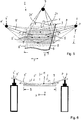
- the Figures 1 to 4 show a device 2 according to the invention for determining the flatness of moving strip material 3 in a first embodiment.
- the device 2 comprises a projection-providing optics 4 for generating a projection pattern 5 on the surface 6 of the strip material 3 and a camera 7 for detecting the projection pattern 5.
- a metallic material can be used as the strip material 3, for example made of a steel or aluminum material, without this to be restricted. Strip material with all technically possible bandwidths B and strip thicknesses D can be used.
- the camera 7 detects the flatness of the strip material during the strip feed movement in the feed direction X, which can also be referred to as the longitudinal direction. It is particularly in Figure 2 Recognizable that the optics 4 is arranged offset transversely to the band material 3, in particular in such a way that it is at a distance from an edge 8 of the band.
- the projection-providing optics 4 is aligned in such a way that the projection pattern 5 generated is at an average projection angle a hits the surface 6, which is in particular between 1 ° and 45 °.
- the projection angle a is preferably greater than or equal to 5 ° and / or less than or equal to 35 °.
- the camera 7 and the projection optics 4 are attached to separate brackets. For high detection accuracy, the camera 7 can be mounted on a carrier in a vibration-decoupled manner, in particular by means of an elastic element.
- the projection-providing optics 4 are attached to a separate frame, which can be part of a processing device.
- the projection pattern 5 extends, as in particular in FIGS Figures 1 and 3 recognizable, over the entire width B of the band 3, in order to also detect a flatness deviation correspondingly in all width regions, that is to say in the edge regions and in the central region of the band.
- the projection pattern 5 extends in the feed direction X of the strip 3 over a length L of preferably less than 100 cm, in particular less than 80 cm, particularly preferably less than 40 cm. Overall, therefore, only a relatively small installation length of the device 2 in the feed direction of the strip material 3 is required, so that a processing system equipped with the device has a correspondingly short construction.
- the projection pattern 5 preferably extends in the direction of movement X of the strip material 3 over a length L of at least 7 cm, in particular at least 10 cm, optionally also at least 20 cm.
- the projection pattern is preferably projected onto only one side of the strip material 3.
- the projection pattern 5 is projected onto the surface 6 in the form of a grid-shaped projection grid.
- the projection grating each comprises a family of lines lx, ly which run in the longitudinal direction X and in the transverse direction Y and intersect at right angles. It goes without saying that the projection grating can also comprise lines which can intersect at an acute or obtuse angle. It is also possible for the projection pattern to expand across the width of the band, in particular to be trapezoidal.
- the grid dimension between repeating grid points, that is, between the intersections of the intersecting lines lx, ly, is between 0.7 mm and 100 mm, in particular between 1.0 mm and 50 mm, possibly also between 10 mm and 30 mm.
- the specified grid dimensions relate in particular to an average grid dimension of the overall projection grid. It is understood that the lower values mentioned can be combined as desired with the upper values mentioned. The degree and position of a possible impurity are clearly visible through a suitable choice of the grid dimension.
- the projection pattern can also have shapes other than a lattice-like structure, for example a diamond-shaped, rectangular or circular structure. The distances between the lines of the first group and the distances between the lines of the crossing second group can also be different. This would result in a rectangular pattern for lines crossing at right angles.
- the camera 7 When viewed in cross section through the arrangement, the camera 7 is arranged at least approximately centrally above the belt 3. With at least approximately in the middle, all positions within a middle third of the band 3 should also be included. Due to the central arrangement, the projection pattern 5 generated by the optics 4 can be captured particularly well by the camera 7.
- the camera 7 and the optics 4 are arranged in a plane E, which in Figure 2 corresponds to the drawing level.
- a light source in the form of a laser is used as projection optics 4, other light sources or imaging optics also being possible.
- light-reflecting optics such as a mirror can also be used, which deflects or reflects a light beam generated by a light source arranged at a distance from it onto the strip material.
- a method according to the invention can be carried out as follows: While the strip material 3 is moved in the feed direction X by means of a strip feed device (not shown separately here), the projection pattern 5 is generated on the surface 6 of the strip material 3. As described above, the projection pattern 5 is projected from a lateral position transverse to the feed direction X, the projection angle a in a cross-sectional plane E, which includes the optics 4, being between 1 ° and 45 °. The projection pattern 5 generated on the surface 6 is continuously recorded and can then be compared with a reference pattern corresponding to the target band profile.
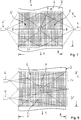
- FIG 4 An irregularity 20 of the determined projection pattern 5 is shown by the target flatness as an example. Specifically, a ripple can be seen in the left band area, which represents a deviation from the actual line structure. This deviation from the straight lattice structure is correspondingly recorded by the camera and processed further in a control unit in order to intervene in the machining process in a correspondingly correcting manner.
- the method or the device 2 are particularly suitable for use in strip processing industrial plants in which high strip tension occurs, such as rolling plants.
- the device or the method can also be used to detect deviations in the plan of the strip material, on which tensile forces of more than 20 N / mm 2 , in particular more than 40 N / mm 2 , in particular more than 60 N / mm 2 , possibly of more than Act 100 N / mm 2 .
- the strip material can be moved, for example, with a feed movement between 15 m / min and 600 m / min, in particular between 50 m / min and 120 m / min, other speeds being possible.
- FIGS Figures 1 to 3 show a device 2 according to the invention in a modified embodiment. This corresponds largely to the embodiment according to the Figures 1 to 3 , so that with regard to the similarities, reference is made to the above description. The same or corresponding details are provided with the same reference numerals as in FIGS Figures 1 to 3 ,
- a difference from the above embodiment is that two optics 4, 4 'are provided in the present case, so that two projection patterns 5, 5' are correspondingly produced on the strip material 3.
- the two optics 4, 4 'in the embodiment according to FIGS Figures 5 to 7 staggered in the longitudinal and transverse directions.
- the two optics 4, 4 'are arranged laterally adjacent to the two opposite edges 8, 8' of the strip material 3.
- the two projection surfaces 5, 5 ′ preferably adjoin one another approximately in the central plane M.
- the right projection surface 5 extends from the right edge 8 to approximately the center M of the band 3, while the left projection surface 5 'extends from the left edge 8' to approximately the center M.
- the areas 21, 21 ' have an overlap. This results in an arrangement that is short in the longitudinal direction.
- the two projection surfaces 5, 5 ' as in Figure 5 shown in the longitudinal direction in complete overlap and adjoin each other in the transverse direction Y of the tape. It is possible that the light intensity of the projection patterns 5, 5 'generated by the two optics 4, 4' decreases towards the edges. In this case, it is favorable that the projection patterns 5, 5 'are generated in such a way that they have a particularly seamless overlap in the transition area, so that an overall projection pattern to be evaluated is generated.
- the Figure 8 shows the projection arrangement of a device 2 according to the invention in a further modified embodiment in plan view of the strip material 3. This largely corresponds to the embodiment according to FIGS Figures 1 to 3 , so that with regard to the similarities, reference is made to the above description. The same or corresponding details are provided with the same reference numerals as in FIGS Figures 1 to 3 ,
- a difference from the above embodiment is that two optics 4, 4 'are provided in the present case, so that two projection patterns 5, 5' are correspondingly produced on the strip material 3.
- the two optics 4, 4 'are in the embodiment according to Figure 8 arranged in the feed direction X of the strip material offset from one another.
- the two optics 4, 4 'are arranged such that their generated projection patterns 5, 5' are arranged adjacent to one another in the direction of advance of the strip 3 or, in particular, merge seamlessly into one another in an overlap region.
- the upstream optics 4 project a projection pattern 5 onto the band section 21, while the downstream ones Optics 4 'projects a projection pattern 5' onto the adjacent band section 21 '.
- the two projection surfaces 5, 5 ′ extend in the transverse direction over the entire width B of the band 3.
- the camera 7 (shown in dashed lines), which is arranged at the same location centrally above the illuminated band sections 21, 21 'as in the above embodiment, accordingly captures the projection patterns 5, 5' from both optics 4, 4 ', the use of several of which Cameras would be conceivable. Otherwise, the present embodiment corresponds in terms of structure and mode of operation to that according to FIGS Figures 1 to 3 , or 5 to 7, the description of which is abbreviated in this respect.
- the Figure 9 shows the projection arrangement of a device 2 according to the invention in a further modified embodiment in plan view of the strip material 3.
- This largely corresponds to the embodiment according to Figure 8 , the description of which is referred to with regard to the similarities.
- the same or corresponding details are provided with the same reference numerals as in Figure 8 , or the previous ones Figures 1 to 7 ,
- the only difference to the embodiment according to Figure 8 consists in the fact that the optics 4, 4 'are arranged on opposite sides of the band 3 in the present case.
- the right optic 4 illuminates the band 3 from the right side, while the left optic 4 'illuminates the band 3 from the left side.
- the optics 4, 4 ' are arranged offset with respect to one another in the feed direction X of the strip material, the projection patterns 5, 5' adjoining one another or passing seamlessly into one another.
- the projection patterns 5, 5 ' can overlap in a transition area.
- the two projection patterns 5, 5 ′ preferably extend over the entire width B of the band 3.
- Figure 10 shows a processing system 10 according to the invention for processing strip material 3.
- Die Figures 11 and 12 show a section of the strip material 3 with an exemplary sheet thickness curve D over the length L.
- the processing takes place in a continuous process, ie the strip material 3 is unwound from the coil 11 by means of a reel 22, passes through the individual processing components and is then rewound to the coil 11 'by means of a second reel 22'.
- the processing system 10 comprises, in the feed direction X of the strip 3, a first strip feed device 12, a processing device 13 for mechanical processing of the strip material 3, a device 2 according to the invention Figures 1 to 3 , and a second tape feed device 14.
- the two tape feed devices 12, 14 each comprise two feed rollers 15, 15 '; 16, 16 'between which the tape is passed, which can also be referred to as drive rollers.
- a tensile force Fx is generated in the feed direction of the strip 3, with which the strip is pulled through the processing device 13.
- the processing device 13 for the mechanical processing of the strip material 3 is designed here in the form of a rolling device for flexible rolling.
- the strip material 3, which has a largely constant sheet thickness D over the length L before the flexible rolling is rolled by means of rolls 17, 17 'in such a way that it receives a variable sheet thickness along the rolling direction X.
- the flatness of the strip material can be controlled by means of an electronic control unit (ECU) in the system according to the invention or the method during rolling, taking into account the flatness determined by the device 2.
- the device 2 continuously detects the projection patterns 5, 5 'detected by the camera 7, which, after comparison with the associated reference pattern, are used as an input signal for controlling the rollers 17, 17'.
- the setting of the sheet thickness can also be monitored and controlled by means of a further electronic control unit, wherein the data determined by a sheet thickness measurement 18 can be used as an input signal for setting the roll gap.
- the strip material 3 has sections 19, 19 ', 19 "which extend transversely to the rolling direction and have different thicknesses D, D', D".
- the strip material 3 is rewound to form the coil 11 'by means of a reel 22', so that it can be fed to the next processing process.
- high tensile forces Fx are required in order to pull the strip 3 through the rolling device 13.
- these tensile forces are essentially generated by the reel 22 ′, with tensile forces of more than 100 N / mm 2 , possibly also more than 120 N / mm, on the strip material 3 in the sections lying between the end-side reel 22 ′ and the rolling device 13. mm 2 , can be applied.
- the high tensile forces lead to a smooth pulling of the strip material 3, so that deviations of the surface from the flatness are difficult to detect.
- the method or device 2 according to the invention is particularly well suited for this, since even small deviations from the reference pattern can be ascertained well with it.
Landscapes
- Engineering & Computer Science (AREA)
- Physics & Mathematics (AREA)
- General Physics & Mathematics (AREA)
- Computer Vision & Pattern Recognition (AREA)
- Mechanical Engineering (AREA)
- Length Measuring Devices By Optical Means (AREA)
Priority Applications (1)
| Application Number | Priority Date | Filing Date | Title |
|---|---|---|---|
| PL18721023T PL3487642T3 (pl) | 2017-04-25 | 2018-04-25 | Sposób i urządzenie do określania płaskości materiału taśmowego oraz układ do przetwarzania z takim urządzeniem |
Applications Claiming Priority (2)
| Application Number | Priority Date | Filing Date | Title |
|---|---|---|---|
| DE102017108786.9A DE102017108786A1 (de) | 2017-04-25 | 2017-04-25 | Verfahren und Vorrichtung zum Ermitteln der Planheit von Bandmaterial und Bearbeitungsanlage mit einer solchen Vorrichtung |
| PCT/EP2018/060633 WO2018197579A1 (de) | 2017-04-25 | 2018-04-25 | Verfahren und vorrichtung zum ermitteln der planheit von bandmaterial und bearbeitungsanlage mit einer solchen vorrichtung |
Publications (2)
| Publication Number | Publication Date |
|---|---|
| EP3487642A1 EP3487642A1 (de) | 2019-05-29 |
| EP3487642B1 true EP3487642B1 (de) | 2020-01-08 |
Family
ID=62089748
Family Applications (1)
| Application Number | Title | Priority Date | Filing Date |
|---|---|---|---|
| EP18721023.2A Active EP3487642B1 (de) | 2017-04-25 | 2018-04-25 | Verfahren und vorrichtung zum ermitteln der planheit von bandmaterial und bearbeitungsanlage mit einer solchen vorrichtung |
Country Status (4)
| Country | Link |
|---|---|
| EP (1) | EP3487642B1 (pl) |
| DE (1) | DE102017108786A1 (pl) |
| PL (1) | PL3487642T3 (pl) |
| WO (1) | WO2018197579A1 (pl) |
Cited By (1)
| Publication number | Priority date | Publication date | Assignee | Title |
|---|---|---|---|---|
| DE102022128499B3 (de) | 2022-10-27 | 2023-11-16 | Thyssenkrupp Steel Europe Ag | Verfahren und Vorrichtung zur Bestimmung der Planheit eines Metallbandes |
Families Citing this family (5)
| Publication number | Priority date | Publication date | Assignee | Title |
|---|---|---|---|---|
| DE102017211818A1 (de) | 2017-07-11 | 2019-01-17 | Continental Reifen Deutschland Gmbh | Fahrzeugreifen mit einer Seitenwandschraffur |
| DE102020000570A1 (de) | 2020-01-29 | 2021-07-29 | Siempelkamp Maschinen- Und Anlagenbau Gmbh | Verfahren zur Überwachung eines Stahlbandes in einer kontinuierlichen Presse und kontinuierliche Presse |
| DE102020006637A1 (de) | 2020-10-29 | 2022-05-05 | Siempelkamp Maschinen- Und Anlagenbau Gmbh | Verfahren zur Überwachung eines Stahlbandes in einer kontinuierlichen Presse auf Materialanhaftungen und kontinuierliche Presse |
| FR3139895B1 (fr) | 2022-09-16 | 2024-12-20 | Constellium Neuf Brisach | Dispositif et procédé de contrôle de planéité d’une tôle métallique. |
| CN115496751B (zh) * | 2022-11-16 | 2023-03-24 | 威海捷诺曼自动化股份有限公司 | 一种纤维缠绕机缠绕检测方法 |
Family Cites Families (10)
| Publication number | Priority date | Publication date | Assignee | Title |
|---|---|---|---|---|
| US5112131A (en) * | 1981-02-27 | 1992-05-12 | Diffracto, Ltd. | Controlled machining of combustion chambers, gears and other surfaces |
| EP0375095B1 (de) * | 1988-12-22 | 1996-01-31 | Preussag Stahl Aktiengesellschaft | Verfahren und Vorrichtung zum Regeln der Bandbreite beim Warmbandwalzen |
| US5615456A (en) * | 1994-08-19 | 1997-04-01 | Hans Oetiker Ag Maschinen- Und Apparate-Fabrik | Tolerance-compensating reusable clamp structure |
| FR2725512B1 (fr) * | 1994-10-07 | 1996-10-31 | Lorraine Laminage | Dispositif d'evaluation de la planeite d'un produit en defilement |
| DE19758466B4 (de) | 1997-03-11 | 2007-10-04 | Betriebsforschungsinstitut VDEh - Institut für angewandte Forschung GmbH | Planheits-Regelungssystem für Metallband |
| DE19932324B8 (de) | 1999-07-10 | 2008-04-10 | Betriebsforschungsinstitut VDEh - Institut für angewandte Forschung GmbH | Verfahren zur Ermittlung der Planheit bzw. der Welligkeit eines bewegten Bandes |
| US6937350B2 (en) * | 2001-06-29 | 2005-08-30 | Massachusetts Institute Of Technology | Apparatus and methods for optically monitoring thickness |
| DE10205132A1 (de) * | 2002-02-07 | 2003-08-28 | Bfi Vdeh Inst Angewandte Forschung Gmbh | Verfahren und Vorrichtung zum optischen Messen der Oberflächenform und zur optischen Oberflächeninspektion von bewegten Bändern in Walz- und Weiterbearbeitungsanlagen |
| EP1991375A1 (en) * | 2006-02-17 | 2008-11-19 | Alcoa Inc. | Application of induction heating to control sheet flatness in cold rolling mills |
| US20070273894A1 (en) * | 2006-05-23 | 2007-11-29 | Johnson James T | Method and apparatus for remote spatial calibration and imaging |
-
2017
- 2017-04-25 DE DE102017108786.9A patent/DE102017108786A1/de not_active Withdrawn
-
2018
- 2018-04-25 EP EP18721023.2A patent/EP3487642B1/de active Active
- 2018-04-25 WO PCT/EP2018/060633 patent/WO2018197579A1/de not_active Ceased
- 2018-04-25 PL PL18721023T patent/PL3487642T3/pl unknown
Non-Patent Citations (1)
| Title |
|---|
| None * |
Cited By (2)
| Publication number | Priority date | Publication date | Assignee | Title |
|---|---|---|---|---|
| DE102022128499B3 (de) | 2022-10-27 | 2023-11-16 | Thyssenkrupp Steel Europe Ag | Verfahren und Vorrichtung zur Bestimmung der Planheit eines Metallbandes |
| WO2024088877A1 (de) | 2022-10-27 | 2024-05-02 | Thyssenkrupp Steel Europe Ag | Verfahren und vorrichtung zur bestimmung der planheit eines metallbandes |
Also Published As
| Publication number | Publication date |
|---|---|
| WO2018197579A1 (de) | 2018-11-01 |
| EP3487642A1 (de) | 2019-05-29 |
| PL3487642T3 (pl) | 2020-07-13 |
| DE102017108786A1 (de) | 2018-06-14 |
Similar Documents
| Publication | Publication Date | Title |
|---|---|---|
| EP3487642B1 (de) | Verfahren und vorrichtung zum ermitteln der planheit von bandmaterial und bearbeitungsanlage mit einer solchen vorrichtung | |
| DE3116278C2 (pl) | ||
| EP2825332B1 (de) | Vorrichtung und verfahren zum richten von metallband | |
| EP2044387B1 (de) | Verfahren und vorrichtung zur dickenmessung grossflächiger glassubstrate | |
| EP2159536B1 (de) | Verfahren zum berührungslosen Messen der Geschwindigkeit und/oder der Länge eines in Längsrichtung bewegten Strangs, insbesondere eines Kabels | |
| EP3009206A1 (de) | Planheitsmessrolle mit messbalken in bandlaufrichtung | |
| WO2014131658A1 (de) | Verfahren zum schneiden einer blechplatine | |
| EP2961561B1 (de) | Verfahren zum schneiden einer blechplatine mit einer vorgegebenen kontur | |
| DE69104169T2 (de) | Verfahren zur Regelung der Kantenabsenkung beim Kaltwalzen von Stahl. | |
| DE112007000641B4 (de) | Kontinuierliche Kaltwalzanlage | |
| EP1460375A2 (de) | Verfahren und Vorrichtung zum geometrischen Vermessen eines Materialbandes | |
| DE102008013488A1 (de) | Vorrichtung zur Dickenmessung und Verfahren hierfür | |
| DE19725726C2 (de) | Verfahren zur Planheitsmessung von Bändern, insbesondere Metallbändern | |
| WO2016177369A1 (de) | Vorrichtung und verfahren zur messung der breite und der dicke eines flächigen objekts | |
| EP2910893B1 (de) | Vorrichtung und verfahren zum ermitteln von planheitsabweichungen beim behandeln eines bandförmigen guts | |
| DE202015106767U1 (de) | Banddickenmessgerät | |
| DE102016113717B4 (de) | Banddickenmessgerät und Verfahren zur Durchführung einer Banddickenmessung | |
| DE202013105426U1 (de) | Spleißvorrichtung zum Überlappspleißen von Cordbandstreifen | |
| DE102018104624B3 (de) | Verfahren und Vorrichtung zur Bestimmung einer Oberfläche | |
| DE102021121568B3 (de) | Vorrichtung und Verfahren zur Bestimmung der Wellenlängen des Laserlichts im Bereich der Messstrecke eines Mehrwellenlängeninterferometers | |
| DE102015121662A1 (de) | Verfahren zur Durchführung einer Banddickenmessung sowie Banddickenmessgerät | |
| WO2008131929A1 (de) | Verfahren zum betrieb einer formgebungsvorrichtung | |
| DE3444931C2 (de) | Verfahren und Vorrichtung zum Walzen von Warmband | |
| DE202019103020U1 (de) | Vorrichtung zur Visualisierung eines Abschnitts einer Bandkontur | |
| EP2365280B1 (de) | Verfahren zur optischen Messung von Schienen |
Legal Events
| Date | Code | Title | Description |
|---|---|---|---|
| STAA | Information on the status of an ep patent application or granted ep patent |
Free format text: STATUS: UNKNOWN |
|
| STAA | Information on the status of an ep patent application or granted ep patent |
Free format text: STATUS: THE INTERNATIONAL PUBLICATION HAS BEEN MADE |
|
| PUAI | Public reference made under article 153(3) epc to a published international application that has entered the european phase |
Free format text: ORIGINAL CODE: 0009012 |
|
| STAA | Information on the status of an ep patent application or granted ep patent |
Free format text: STATUS: REQUEST FOR EXAMINATION WAS MADE |
|
| 17P | Request for examination filed |
Effective date: 20190221 |
|
| AK | Designated contracting states |
Kind code of ref document: A1 Designated state(s): AL AT BE BG CH CY CZ DE DK EE ES FI FR GB GR HR HU IE IS IT LI LT LU LV MC MK MT NL NO PL PT RO RS SE SI SK SM TR |
|
| AX | Request for extension of the european patent |
Extension state: BA ME |
|
| GRAP | Despatch of communication of intention to grant a patent |
Free format text: ORIGINAL CODE: EPIDOSNIGR1 |
|
| STAA | Information on the status of an ep patent application or granted ep patent |
Free format text: STATUS: GRANT OF PATENT IS INTENDED |
|
| DAV | Request for validation of the european patent (deleted) | ||
| DAX | Request for extension of the european patent (deleted) | ||
| INTG | Intention to grant announced |
Effective date: 20190716 |
|
| GRAS | Grant fee paid |
Free format text: ORIGINAL CODE: EPIDOSNIGR3 |
|
| GRAJ | Information related to disapproval of communication of intention to grant by the applicant or resumption of examination proceedings by the epo deleted |
Free format text: ORIGINAL CODE: EPIDOSDIGR1 |
|
| GRAL | Information related to payment of fee for publishing/printing deleted |
Free format text: ORIGINAL CODE: EPIDOSDIGR3 |
|
| STAA | Information on the status of an ep patent application or granted ep patent |
Free format text: STATUS: REQUEST FOR EXAMINATION WAS MADE |
|
| GRAR | Information related to intention to grant a patent recorded |
Free format text: ORIGINAL CODE: EPIDOSNIGR71 |
|
| STAA | Information on the status of an ep patent application or granted ep patent |
Free format text: STATUS: GRANT OF PATENT IS INTENDED |
|
| GRAA | (expected) grant |
Free format text: ORIGINAL CODE: 0009210 |
|
| STAA | Information on the status of an ep patent application or granted ep patent |
Free format text: STATUS: THE PATENT HAS BEEN GRANTED |
|
| INTC | Intention to grant announced (deleted) | ||
| AK | Designated contracting states |
Kind code of ref document: B1 Designated state(s): AL AT BE BG CH CY CZ DE DK EE ES FI FR GB GR HR HU IE IS IT LI LT LU LV MC MK MT NL NO PL PT RO RS SE SI SK SM TR |
|
| INTG | Intention to grant announced |
Effective date: 20191203 |
|
| REG | Reference to a national code |
Ref country code: GB Ref legal event code: FG4D Free format text: NOT ENGLISH |
|
| REG | Reference to a national code |
Ref country code: CH Ref legal event code: EP |
|
| REG | Reference to a national code |
Ref country code: DE Ref legal event code: R096 Ref document number: 502018000630 Country of ref document: DE |
|
| REG | Reference to a national code |
Ref country code: IE Ref legal event code: FG4D Free format text: LANGUAGE OF EP DOCUMENT: GERMAN |
|
| REG | Reference to a national code |
Ref country code: AT Ref legal event code: REF Ref document number: 1222053 Country of ref document: AT Kind code of ref document: T Effective date: 20200215 |
|
| REG | Reference to a national code |
Ref country code: NL Ref legal event code: MP Effective date: 20200108 |
|
| REG | Reference to a national code |
Ref country code: LT Ref legal event code: MG4D |
|
| PG25 | Lapsed in a contracting state [announced via postgrant information from national office to epo] |
Ref country code: LT Free format text: LAPSE BECAUSE OF FAILURE TO SUBMIT A TRANSLATION OF THE DESCRIPTION OR TO PAY THE FEE WITHIN THE PRESCRIBED TIME-LIMIT Effective date: 20200108 Ref country code: NO Free format text: LAPSE BECAUSE OF FAILURE TO SUBMIT A TRANSLATION OF THE DESCRIPTION OR TO PAY THE FEE WITHIN THE PRESCRIBED TIME-LIMIT Effective date: 20200408 Ref country code: RS Free format text: LAPSE BECAUSE OF FAILURE TO SUBMIT A TRANSLATION OF THE DESCRIPTION OR TO PAY THE FEE WITHIN THE PRESCRIBED TIME-LIMIT Effective date: 20200108 Ref country code: FI Free format text: LAPSE BECAUSE OF FAILURE TO SUBMIT A TRANSLATION OF THE DESCRIPTION OR TO PAY THE FEE WITHIN THE PRESCRIBED TIME-LIMIT Effective date: 20200108 Ref country code: NL Free format text: LAPSE BECAUSE OF FAILURE TO SUBMIT A TRANSLATION OF THE DESCRIPTION OR TO PAY THE FEE WITHIN THE PRESCRIBED TIME-LIMIT Effective date: 20200108 Ref country code: PT Free format text: LAPSE BECAUSE OF FAILURE TO SUBMIT A TRANSLATION OF THE DESCRIPTION OR TO PAY THE FEE WITHIN THE PRESCRIBED TIME-LIMIT Effective date: 20200531 |
|
| PG25 | Lapsed in a contracting state [announced via postgrant information from national office to epo] |
Ref country code: GR Free format text: LAPSE BECAUSE OF FAILURE TO SUBMIT A TRANSLATION OF THE DESCRIPTION OR TO PAY THE FEE WITHIN THE PRESCRIBED TIME-LIMIT Effective date: 20200409 Ref country code: BG Free format text: LAPSE BECAUSE OF FAILURE TO SUBMIT A TRANSLATION OF THE DESCRIPTION OR TO PAY THE FEE WITHIN THE PRESCRIBED TIME-LIMIT Effective date: 20200408 Ref country code: HR Free format text: LAPSE BECAUSE OF FAILURE TO SUBMIT A TRANSLATION OF THE DESCRIPTION OR TO PAY THE FEE WITHIN THE PRESCRIBED TIME-LIMIT Effective date: 20200108 Ref country code: LV Free format text: LAPSE BECAUSE OF FAILURE TO SUBMIT A TRANSLATION OF THE DESCRIPTION OR TO PAY THE FEE WITHIN THE PRESCRIBED TIME-LIMIT Effective date: 20200108 Ref country code: SE Free format text: LAPSE BECAUSE OF FAILURE TO SUBMIT A TRANSLATION OF THE DESCRIPTION OR TO PAY THE FEE WITHIN THE PRESCRIBED TIME-LIMIT Effective date: 20200108 Ref country code: IS Free format text: LAPSE BECAUSE OF FAILURE TO SUBMIT A TRANSLATION OF THE DESCRIPTION OR TO PAY THE FEE WITHIN THE PRESCRIBED TIME-LIMIT Effective date: 20200508 |
|
| REG | Reference to a national code |
Ref country code: DE Ref legal event code: R097 Ref document number: 502018000630 Country of ref document: DE |
|
| PG25 | Lapsed in a contracting state [announced via postgrant information from national office to epo] |
Ref country code: DK Free format text: LAPSE BECAUSE OF FAILURE TO SUBMIT A TRANSLATION OF THE DESCRIPTION OR TO PAY THE FEE WITHIN THE PRESCRIBED TIME-LIMIT Effective date: 20200108 Ref country code: SM Free format text: LAPSE BECAUSE OF FAILURE TO SUBMIT A TRANSLATION OF THE DESCRIPTION OR TO PAY THE FEE WITHIN THE PRESCRIBED TIME-LIMIT Effective date: 20200108 Ref country code: EE Free format text: LAPSE BECAUSE OF FAILURE TO SUBMIT A TRANSLATION OF THE DESCRIPTION OR TO PAY THE FEE WITHIN THE PRESCRIBED TIME-LIMIT Effective date: 20200108 Ref country code: SK Free format text: LAPSE BECAUSE OF FAILURE TO SUBMIT A TRANSLATION OF THE DESCRIPTION OR TO PAY THE FEE WITHIN THE PRESCRIBED TIME-LIMIT Effective date: 20200108 Ref country code: RO Free format text: LAPSE BECAUSE OF FAILURE TO SUBMIT A TRANSLATION OF THE DESCRIPTION OR TO PAY THE FEE WITHIN THE PRESCRIBED TIME-LIMIT Effective date: 20200108 Ref country code: ES Free format text: LAPSE BECAUSE OF FAILURE TO SUBMIT A TRANSLATION OF THE DESCRIPTION OR TO PAY THE FEE WITHIN THE PRESCRIBED TIME-LIMIT Effective date: 20200108 |
|
| PLBE | No opposition filed within time limit |
Free format text: ORIGINAL CODE: 0009261 |
|
| STAA | Information on the status of an ep patent application or granted ep patent |
Free format text: STATUS: NO OPPOSITION FILED WITHIN TIME LIMIT |
|
| PG25 | Lapsed in a contracting state [announced via postgrant information from national office to epo] |
Ref country code: MC Free format text: LAPSE BECAUSE OF FAILURE TO SUBMIT A TRANSLATION OF THE DESCRIPTION OR TO PAY THE FEE WITHIN THE PRESCRIBED TIME-LIMIT Effective date: 20200108 |
|
| 26N | No opposition filed |
Effective date: 20201009 |
|
| PG25 | Lapsed in a contracting state [announced via postgrant information from national office to epo] |
Ref country code: IT Free format text: LAPSE BECAUSE OF FAILURE TO SUBMIT A TRANSLATION OF THE DESCRIPTION OR TO PAY THE FEE WITHIN THE PRESCRIBED TIME-LIMIT Effective date: 20200108 Ref country code: LU Free format text: LAPSE BECAUSE OF NON-PAYMENT OF DUE FEES Effective date: 20200425 Ref country code: FR Free format text: LAPSE BECAUSE OF NON-PAYMENT OF DUE FEES Effective date: 20200430 |
|
| REG | Reference to a national code |
Ref country code: BE Ref legal event code: MM Effective date: 20200430 |
|
| PG25 | Lapsed in a contracting state [announced via postgrant information from national office to epo] |
Ref country code: BE Free format text: LAPSE BECAUSE OF NON-PAYMENT OF DUE FEES Effective date: 20200430 |
|
| PG25 | Lapsed in a contracting state [announced via postgrant information from national office to epo] |
Ref country code: IE Free format text: LAPSE BECAUSE OF NON-PAYMENT OF DUE FEES Effective date: 20200425 |
|
| PG25 | Lapsed in a contracting state [announced via postgrant information from national office to epo] |
Ref country code: LI Free format text: LAPSE BECAUSE OF NON-PAYMENT OF DUE FEES Effective date: 20210430 Ref country code: CH Free format text: LAPSE BECAUSE OF NON-PAYMENT OF DUE FEES Effective date: 20210430 |
|
| PG25 | Lapsed in a contracting state [announced via postgrant information from national office to epo] |
Ref country code: TR Free format text: LAPSE BECAUSE OF FAILURE TO SUBMIT A TRANSLATION OF THE DESCRIPTION OR TO PAY THE FEE WITHIN THE PRESCRIBED TIME-LIMIT Effective date: 20200108 Ref country code: MT Free format text: LAPSE BECAUSE OF FAILURE TO SUBMIT A TRANSLATION OF THE DESCRIPTION OR TO PAY THE FEE WITHIN THE PRESCRIBED TIME-LIMIT Effective date: 20200108 Ref country code: CY Free format text: LAPSE BECAUSE OF FAILURE TO SUBMIT A TRANSLATION OF THE DESCRIPTION OR TO PAY THE FEE WITHIN THE PRESCRIBED TIME-LIMIT Effective date: 20200108 |
|
| PG25 | Lapsed in a contracting state [announced via postgrant information from national office to epo] |
Ref country code: MK Free format text: LAPSE BECAUSE OF FAILURE TO SUBMIT A TRANSLATION OF THE DESCRIPTION OR TO PAY THE FEE WITHIN THE PRESCRIBED TIME-LIMIT Effective date: 20200108 Ref country code: AL Free format text: LAPSE BECAUSE OF FAILURE TO SUBMIT A TRANSLATION OF THE DESCRIPTION OR TO PAY THE FEE WITHIN THE PRESCRIBED TIME-LIMIT Effective date: 20200108 |
|
| GBPC | Gb: european patent ceased through non-payment of renewal fee |
Effective date: 20220425 |
|
| PG25 | Lapsed in a contracting state [announced via postgrant information from national office to epo] |
Ref country code: GB Free format text: LAPSE BECAUSE OF NON-PAYMENT OF DUE FEES Effective date: 20220425 |
|
| PG25 | Lapsed in a contracting state [announced via postgrant information from national office to epo] |
Ref country code: SI Free format text: LAPSE BECAUSE OF FAILURE TO SUBMIT A TRANSLATION OF THE DESCRIPTION OR TO PAY THE FEE WITHIN THE PRESCRIBED TIME-LIMIT Effective date: 20200108 |
|
| REG | Reference to a national code |
Ref country code: AT Ref legal event code: MM01 Ref document number: 1222053 Country of ref document: AT Kind code of ref document: T Effective date: 20230425 |
|
| PG25 | Lapsed in a contracting state [announced via postgrant information from national office to epo] |
Ref country code: AT Free format text: LAPSE BECAUSE OF NON-PAYMENT OF DUE FEES Effective date: 20230425 |
|
| PG25 | Lapsed in a contracting state [announced via postgrant information from national office to epo] |
Ref country code: AT Free format text: LAPSE BECAUSE OF NON-PAYMENT OF DUE FEES Effective date: 20230425 |
|
| PGFP | Annual fee paid to national office [announced via postgrant information from national office to epo] |
Ref country code: PL Payment date: 20250325 Year of fee payment: 8 |
|
| PGFP | Annual fee paid to national office [announced via postgrant information from national office to epo] |
Ref country code: DE Payment date: 20250414 Year of fee payment: 8 |
|
| PGFP | Annual fee paid to national office [announced via postgrant information from national office to epo] |
Ref country code: AT Payment date: 20260410 Year of fee payment: 5 |
|
| PGFP | Annual fee paid to national office [announced via postgrant information from national office to epo] |
Ref country code: CZ Payment date: 20260326 Year of fee payment: 9 |