EP3487259B1 - Verfahren und vorrichtung zur aktualisierung von systeminformationen in einem drahtloskommunikationssystem - Google Patents
Verfahren und vorrichtung zur aktualisierung von systeminformationen in einem drahtloskommunikationssystem Download PDFInfo
- Publication number
- EP3487259B1 EP3487259B1 EP17851107.7A EP17851107A EP3487259B1 EP 3487259 B1 EP3487259 B1 EP 3487259B1 EP 17851107 A EP17851107 A EP 17851107A EP 3487259 B1 EP3487259 B1 EP 3487259B1
- Authority
- EP
- European Patent Office
- Prior art keywords
- system information
- paging
- drx
- paging message
- changed
- Prior art date
- Legal status (The legal status is an assumption and is not a legal conclusion. Google has not performed a legal analysis and makes no representation as to the accuracy of the status listed.)
- Active
Links
Images


Classifications
-
- H—ELECTRICITY
- H04—ELECTRIC COMMUNICATION TECHNIQUE
- H04W—WIRELESS COMMUNICATION NETWORKS
- H04W68/00—User notification, e.g. alerting and paging, for incoming communication, change of service or the like
- H04W68/02—Arrangements for increasing efficiency of notification or paging channel
-
- H—ELECTRICITY
- H04—ELECTRIC COMMUNICATION TECHNIQUE
- H04W—WIRELESS COMMUNICATION NETWORKS
- H04W48/00—Access restriction; Network selection; Access point selection
- H04W48/08—Access restriction or access information delivery, e.g. discovery data delivery
-
- H—ELECTRICITY
- H04—ELECTRIC COMMUNICATION TECHNIQUE
- H04W—WIRELESS COMMUNICATION NETWORKS
- H04W24/00—Supervisory, monitoring or testing arrangements
- H04W24/02—Arrangements for optimising operational condition
-
- H—ELECTRICITY
- H04—ELECTRIC COMMUNICATION TECHNIQUE
- H04W—WIRELESS COMMUNICATION NETWORKS
- H04W36/00—Hand-off or reselection arrangements
- H04W36/0005—Control or signalling for completing the hand-off
- H04W36/0055—Transmission or use of information for re-establishing the radio link
-
- H—ELECTRICITY
- H04—ELECTRIC COMMUNICATION TECHNIQUE
- H04W—WIRELESS COMMUNICATION NETWORKS
- H04W48/00—Access restriction; Network selection; Access point selection
- H04W48/08—Access restriction or access information delivery, e.g. discovery data delivery
- H04W48/12—Access restriction or access information delivery, e.g. discovery data delivery using downlink control channel
-
- H—ELECTRICITY
- H04—ELECTRIC COMMUNICATION TECHNIQUE
- H04W—WIRELESS COMMUNICATION NETWORKS
- H04W68/00—User notification, e.g. alerting and paging, for incoming communication, change of service or the like
- H04W68/005—Transmission of information for alerting of incoming communication
-
- H—ELECTRICITY
- H04—ELECTRIC COMMUNICATION TECHNIQUE
- H04W—WIRELESS COMMUNICATION NETWORKS
- H04W76/00—Connection management
- H04W76/20—Manipulation of established connections
- H04W76/27—Transitions between radio resource control [RRC] states
-
- H—ELECTRICITY
- H04—ELECTRIC COMMUNICATION TECHNIQUE
- H04W—WIRELESS COMMUNICATION NETWORKS
- H04W76/00—Connection management
- H04W76/20—Manipulation of established connections
- H04W76/28—Discontinuous transmission [DTX]; Discontinuous reception [DRX]
-
- H—ELECTRICITY
- H04—ELECTRIC COMMUNICATION TECHNIQUE
- H04W—WIRELESS COMMUNICATION NETWORKS
- H04W88/00—Devices specially adapted for wireless communication networks, e.g. terminals, base stations or access point devices
- H04W88/08—Access point devices
-
- Y—GENERAL TAGGING OF NEW TECHNOLOGICAL DEVELOPMENTS; GENERAL TAGGING OF CROSS-SECTIONAL TECHNOLOGIES SPANNING OVER SEVERAL SECTIONS OF THE IPC; TECHNICAL SUBJECTS COVERED BY FORMER USPC CROSS-REFERENCE ART COLLECTIONS [XRACs] AND DIGESTS
- Y02—TECHNOLOGIES OR APPLICATIONS FOR MITIGATION OR ADAPTATION AGAINST CLIMATE CHANGE
- Y02D—CLIMATE CHANGE MITIGATION TECHNOLOGIES IN INFORMATION AND COMMUNICATION TECHNOLOGIES [ICT], I.E. INFORMATION AND COMMUNICATION TECHNOLOGIES AIMING AT THE REDUCTION OF THEIR OWN ENERGY USE
- Y02D30/00—Reducing energy consumption in communication networks
- Y02D30/70—Reducing energy consumption in communication networks in wireless communication networks
Definitions
- the disclosure relates to a wireless communication system. More specifically, the disclosure relates to a method and device for updating system information in a wireless communication system.
- the 5G or pre-5G communication system is also called a 'Beyond 4G Network' or a 'Post LTE System'.
- the 5G communication system is considered to be implemented in higher frequency (mmWave) bands, e.g., 60GHz bands, so as to accomplish higher data rates.
- mmWave e.g., 60GHz bands
- MIMO massive multiple-input multiple-output
- FD-MIMO Full Dimensional MIMO
- array antenna an analog beam forming, large scale antenna techniques are discussed in 5G communication systems.
- RANs Cloud Radio Access Networks
- D2D device-to-device
- CoMP Coordinated Multi-Points
- FQAM Hybrid FSK and QAM Modulation
- SWSC sliding window superposition coding
- ACM advanced coding modulation
- FBMC filter bank multi carrier
- NOMA non-orthogonal multiple access
- SCMA sparse code multiple access
- the Internet which is a human centered connectivity network where humans generate and consume information
- IoT Internet of Things
- IoE Internet of Everything
- sensing technology “wired/wireless communication and network infrastructure”, “service interface technology”, and “Security technology”
- M2M Machine-to-Machine
- MTC Machine Type Communication
- Such an loT environment may provide intelligent Internet technology services that create a new value to human life by collecting and analyzing data generated among connected things.
- IoT may be applied to a variety of fields including smart home, smart building, smart city, smart car or connected cars, smart grid, health care, smart appliances and advanced medical services through convergence and combination between existing Information Technology (IT) and various industrial applications.
- IT Information Technology
- 5G communication systems to loT networks.
- technologies such as a sensor network, Machine Type Communication (MTC), and Machine-to-Machine (M2M) communication may be implemented by beamforming, MIMO, and array antennas.
- Application of a cloud Radio Access Network (RAN) as the above-described Big Data processing technology may also be considered to be as an example of convergence between the 5G technology and the loT technology.
- RAN Radio Access Network
- a wireless communication system has been developed to provide communication while securing a user's mobility.
- the wireless communication technology has recently been dramatically advanced, and thus the communication system technology continues to evolve.
- Such a wireless communication system has reached to provide high-speed data communication service in addition to voice communication with the help of the rapid development of the technology.
- Performance of the devices becomes high to provide the functions of the existing wireless communication terminal.
- advanced power reduction performance becomes an important requirement because the size of a battery is smaller than that of the existing mobile communication terminal due to a reduced size.
- the mobile communication terminal needs to improve its power reduction performance due to the diversification of utilization, user convenience, etc.
- a terminal may operate in discontinuous reception (DRX) in order to reduce power consumption.
- the terminal may perform a reception operation in order to reduce a paging signal from a base station.
- the paging signal is not frequently transmitted. Accordingly, if the terminal performs a reception operation up to the time when a paging signal is not received, a power loss increases. Accordingly, in order to reduce power consumption, the terminal may attempt to receive a paging signal by periodically performing a reception operation during a specific time period only. This may be called DRX.
- eDRX extended DRX
- a base station may notify a terminal that system information has been changed through a paging message.
- the paging message may not be received.
- the terminal may not be aware of whether system information has been changed. Accordingly, there is a need for a method for a terminal to be aware of whether system information has been changed.
- US 2016/192434A1 teaches indicating all the system information changes by sending paging messages to a UE. INTEL CORPORATION: "Email discussion report on [91#32][LTE/eDRX] eDRX and H- SFN range", 3GPP DRAFT; R2-154294_EMAIL-DISCUSSION 91-32 EDRX H-SFN, vol.
- RAN WG2 no. Malmö, 4 October 2015 , teaches that SI change notification through paging should be supported, and paging notification is anyway needed for change of ETWS/CMAS/EAB SIBs.
- WO 2016/022748A1 discloses using a paging message to provide a UE with a modification indication US 2014/362752A1 discloses indicating SI modification to a UE when there has been such a modification.
- the disclosure provides a method for a terminal to effectively update changed system information by identifying whether system information has been changed when eDRX is applied.
- a terminal can efficiently update system information and efficiently perform an eDRX operation by identifying whether system information has been changed when eDRX is applied.
- each block of the flowchart illustrations and combinations of the blocks in the flowchart illustrations can be executed by computer program instructions.
- These computer program instructions may be mounted on the processor of a general purpose computer, a special purpose computer, or other programmable data processing apparatus, so that the instructions executed by the processor of the computer or other programmable data processing apparatus create means for executing the functions specified in the flowchart block(s).
- These computer program instructions may also be stored in computer-usable or computer-readable memory that can direct a computer or other programmable data processing equipment to function in a particular manner, such that the instructions stored in the computer-usable or computer-readable memory produce an article of manufacture including instruction means that implement the function specified in the flowchart block(s).
- the computer program instructions may also be loaded on a computer or other programmable data processing apparatus to cause a series of operational steps to be performed on the computer or other programmable apparatus to produce a computer-executed process, so that the instructions performing the computer or other programmable apparatus provide steps for executing the functions described in the flowchart block(s).
- each block of the flowchart illustrations may represent a portion of a module, a segment, or code, which includes one or more executable instructions for implementing a specified logical function(s). It should also be noted that in some alternative implementations, the functions noted in the blocks may occur out of order. For example, two blocks shown in succession may in fact be executed substantially concurrently, or the blocks may sometimes be executed in the reverse order, depending upon the functionality involved.
- the term "unit”, as used in the present embodiment means software or a hardware component, such as a field programmable gate array (FPGA) or an application-specific integrated circuit (ASIC), and the “unit” performs specific tasks.
- the “unit” may advantageously be configured to reside on an addressable storage medium and configured to operate on one or more processors.
- the “unit” may include, for example, components, such as software components, object-oriented software components, class components, and task components, processes, functions, attributes, procedures, subroutines, segments of program code, drivers, firmware, microcode, circuitry, data, databases, data structures, tables, arrays, and variables.
- the functionalities provided in the components and "units” may be combined into fewer components and “units” or may be further separated into additional components and “units.” Furthermore, the components and “units” may be implemented to operate on one or more CPUs within a device or a security multimedia card.
- the disclosure relates to a method and device for effectively updating system information by a terminal to which a long DRX cycle has been applied in a mobile communication system.
- FIG. 1 is a diagram showing the configuration of an LTE system to which the disclosure is applied.
- a radio access network of the LTE system includes evolved Node Bs (hereinafter referred to as “ENBs” or “Node Bs” or “base stations”) 105, 110, 115 and 120, a mobile management entity (MME) 125 and a serving-gateway (may be hereinafter referred to as an "S-GW') 130.
- ENBs evolved Node Bs
- MME mobile management entity
- S-GW' serving-gateway
- a user equipment (may be hereinafter referred to a "UE” or a "terminal”) 135 may access an external network through the ENB 105-120 and the S-GW 130.
- the ENBs 105 - 120 may correspond to the NodeBs of the existing universal mobile telecommunication system (UMTS).
- the ENB is connected to the UE 135 through a radio channel and may perform a function more complex than that of the existing Node B.
- UMTS universal mobile telecommunication system
- all of types of user traffic including a real-time service, such as voice over IP (VoIP) through the Internet protocol are served through a shared channel.
- VoIP voice over IP
- the ENBs 105 - 120 may be in charge of such a device. In general, one ENB controls multiple cells.
- the LTE system uses orthogonal frequency division multiplexing (hereinafter referred to as "OFDM”) as a radio access technology in a 20 MHz bandwidth, for example.
- OFDM orthogonal frequency division multiplexing
- the LTE system may adopt an adaptive modulation & coding (hereinafter referred to as "AMC”) scheme for determining a modulation scheme and a channel coding rate based on the channel state of a UE.
- AMC adaptive modulation & coding
- the S-GW 130 is an apparatus for providing a data bearer, and may generate or remove a data bearer under the control of the MME 125.
- the MME 145 is an apparatus responsible for various control functions in addition to a mobility management function for a UE, and may be connected to multiple ENBs.
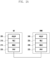
- FIG. 2A is a diagram showing radio protocol architecture in the existing LTE system.
- the radio protocol of the LTE system may include packet data convergence protocol layers (hereinafter referred to as PDCPs 205 and 240, radio link control (hereinafter referred to as RLCs 210 and 235, medium access control (hereinafter referred to as MACs 215 and 230, and physical layers (PHYs) 220 and 225 in a UE and an ENB, respectively.
- PDCPs 205 and 240 packet data convergence protocol layers
- RLCs 210 and 235 radio link control
- MACs 215 and 230 medium access control
- PHYs physical layers
- the PDCP 205, 240 may be responsible for an operation, such as IP header compression/decompression.
- Major functions of the PDCP are as follows.
- the radio link control 210, 235 may perform an automatic repeat request (may be hereinafter referred to as an ARQ) operation by reconfiguring a PDCP packet data unit (PDU) received from the PDCP layer in a proper side.
- An ARQ automatic repeat request
- PDU packet data unit
- the MAC 215, 230 may be connected to several RLC layer devices configured in one UE, and may perform an operation of multiplexing RLC PDUs, received from the RLC layer, into a MAC PDU and demultiplexing RLC PDUs from a MAC PDU.
- Major functions of the MAC are as follows.
- the physical layer 220, 225 may perform an operation of channel-coding and modulating higher layer data, producing an OFDM symbol and transmitting it to a radio channel or demodulating an OFDM symbol received through a radio channel, channel-decoding the demodulated symbol, and delivering it to a higher layer.
- eDRX extended DRX
- DRX operating in the existing DRX cycle may be referred to as first DRX
- DRX operating in an extended cycle may be referred to as a second cycle or a second DRX cycle
- eDRX or second DRX DRX operating in the second cycle
- the first DRX may be defined as DRX operating in the first cycle
- the second DRX may be defined as DRX operating in the second cycle
- the second cycle may include a cycle longer than the first cycle.
- the first DRX operation of UEs in the standby state may be performed through Equation 1 below.
- a system frame number (SFN) may increase by 1 every radio frame.
- SFN system frame number
- a UE may perform a reception operation by the first DRX.
- a radio frame in which a paging signal is transmitted may be referred to as a paging frame (PF).
- PF paging frame
- PO paging occasion
- SFN mod T T div N * UE _ ID mod N
- the SFN may be transmitted to a UE through a master information block (MIB). 8 bits of an MIB transmitted through a physical broadcast channel (PBCH) may indicate an SFN.
- MIB master information block
- PBCH physical broadcast channel
- the first DRX cycle information (T) and the paging-related first parameter (nB) may be provided through an SIB.
- the first DRX cycle information (T) and the paging-related first parameter (nB) may be included in SystemlnformationBlockType2 (SIB2) and provided from a base station.
- SIB2 SystemlnformationBlockType2
- the first DRX cycle information (T) may have one value of ⁇ rf32, rf64, rf128, rf256 ⁇ .
- r32 may indicate a 32-radio frame length. That is, r32 may mean 320 ms.
- the paging-related first parameter (nB) may indicate a paging number or a paging frequency.
- the first DRX cycle information (T) and the paging-related first parameter (nB) provided through an SIB may be referred to as first DRX configuration information or a first DRX parameter.
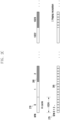
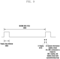
- FIG. 2B is a diagram showing a paging occasion in first DRX.
- a system frame number may increase by 1 every radio frame (250). Furthermore, the value of the system frame number (SFN) may be reset to 0 in 1024 cycles (255).
- paging of the same pattern may be repeated every SFN cycle (260). Furthermore, from Equation 1, it may be seen that a maximum cycle of the first DRX is 2.56 seconds and although the first DRX cycle is increased to a maximum extent, it cannot exceed the cycle of an SFN, that is, 10.24 seconds. In other words, in order to reduce power consumption, the SFN cycle needs to be increased in order to increase the first DRX cycle to 10.24 seconds or more.
- additional SFN bits may be included in the existing or new SIB, and a UE operation of receiving them may be defined.
- the SFN bits may be increased by 1 every SFN cycle.
- a value indicated by the additional SFN bits may be referred to as a hyper system frame number (hyper SFN: HFN).
- An SIB including the additional SFN bits does not need to be received by all UEs, and only a UE to which a very long DRX cycle has been applied may attempt to receive the SIB. Furthermore, a system information change indicator (systemlnfoModification IE), included in system information change-related information (systemInfoValueTag value (one information (IE) included in an SIB1) and paging increased by 1 whenever SIB information is changed and to notify whether system information (SI) has been changed, is not influenced by a change in the SFN bits value. That is, although the SFN bits value is changed, the system information change-related information (systemlnfoValueTag IE) is not updated, and the system information change indicator (systemlnfoModification IE) is not transmitted through paging.
- system information change indicator systemlnfoModification IE
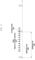
- FIG. 3 is a diagram for illustrating a process for a second DRX operation.
- an HFN may be increase by 1 every SFN cycle. That is, an HFN 270 may include 1024 SFNs 375. Furthermore, the SFN may increase by 1 every radio frame (375).
- a base station may generate paging according to Equation 1 in an SFN cycle determined by Equation 2 to be described later (385).
- a method of receiving a paging signal several times during a determined DRX period is assumed.
- a paging occasion may be determined through a two-step process.
- an SFN cycle in which paging will occur may be determined.
- Added SFN bits may have a value increased by 1 every SFN cycle.
- a value indicated by SFN bits (SFB bits) added as described above may be defined as a hyper system frame number (HFN).
- a UE may identify an SFN cycle in which paging will occur using Equation 2.
- an SFN cycle (or HFN) in which paging will occur may be referred to as a paging hyper frame (PHF).
- HFN mod T ′ T div N ′ * UE _ ID mod N ′ wherein
- the second DRX cycle information (T') and the paging-related second parameter (nB') value may be provided by a base station through an SIB.
- the second DRX cycle information (T') and the paging-related second parameter (nB') may be included in an SIB2 like the first DRX cycle information (T) and the paging-related first parameter (nB) or may be included in an SIB and transmitted.
- the second DRX cycle information (T') and the paging-related second parameter (nB') provided through an SIB may be referred to as second DRX configuration information or a second DRX parameter.
- a UE ID may be derived by the same IMSI module operation as that of a common UE.
- a group ID may also be applied because a device may be indicated in a group ID form.
- a UE may determine a PHF, that is, an SFN cycle in which paging will occur, and may determine whether paging will occur in which radio frames in the corresponding SFN cycle. The UE may identify a radio frame in which paging will occur in the corresponding SFN cycle using Equation 1.
- a paging generation occasion is defined in two steps as described above and communication devices have a DRX cycle, power consumption can be greatly reduced. Furthermore, there is an advantage in that the paging reception probability can be increased because paging may repeatedly occur based on the first DRX cycle information (T), paging-related first parameter (nB) configuration in the SFN cycle determined in the first step.
- T first DRX cycle information
- nB paging-related first parameter
- a UE operating in the second DRX may perform a DRX operation in a first cycle during a given period when a second cycle is received.
- the given period may be referred to as a paging time window (PTW).
- PGW paging time window
- the reception probability of paging can be increased because the paging can be repeatedly received during a given period as described above.
- FIG. 3 is a diagram for illustrating a process for a second DRX operation.
- an eNB 303 may transmit system information to a UE 301 at operation S310.
- the eNB 303 may notify the UE whether it supports second DRX (eDRX) using the system information. If the eNB 303 supports the second DRX, it may transmit system information, including second DRX capability (eDRX capability) information, to the UE.
- the second DRX capability information may include information indicating whether the second DRX is supported.
- the eNB may notify the UE whether it supports the second DRX using system information 1 (SIB 1).
- the UE that has received the system information may identify whether the eNB supports the second DRX based on the system information.
- the UE may transmit second DRX (eDRX)-related information to an MME 305 through the eNB.
- the second DRX-related information may include second DRX cycle information. If it is determined that the application of the second DRX is necessary, the UE may transmit a request message (e.g., ATTACH request message or TAU request message), including the second DRX-related information, to the MME.
- a request message e.g., ATTACH request message or TAU request message
- the second DRX-related information may include second DRX cycle information. That is, if it is determined that the application of the second DRX is necessary, the UE may transmit the request message, including desired second DRX cycle information, to the MME.
- the MME 305 may transmit the second DRX-related information to the UE at operation S330.
- the MME may transmit an ATTACH response message or TAU response message, including the second DRX-related information, to the UE.
- the second DRX-related information may include second DRX cycle information.
- the MME may transmit the second DRX cycle information received from the UE or may transmit desired second DRX cycle information to the UE.
- second DRX cycle information is not included in the response message (ATTACH response message or TAU response message)
- the UE may not perform a second DRX operation.
- the UE may perform a second DRX operation using the second DRX cycle information received from the MME.
- the UE that has received the second DRX-related information from the MME may perform paging monitoring using the second DRX (eDRX) cycle.
- the MME 305 may deliver paging, including the second DRX (eDRX)-related information (e.g., cycle information), to the eNB at operation S340.
- eDRX second DRX-related information
- the eNB may identify the second DRX-related information included in the paging message. Accordingly, the eNB may transmit paging to the UE by applying the second DRX (eDRX) cycle at operation S350.
- eDRX second DRX
- the MME may be aware of whether a given UE drives second DRX (eDRX), and may have stored second DRX (eDRX) cycle information applied to the UE that drives the second DRX.
- eDRX second DRX
- FIG. 4A is a diagram showing a first DRX operation according to the disclosure.
- a UE needs to monitor paging delivered from a network in order to identify whether there is a cell intended therefor or a given service request.
- the UE may perform paging monitoring in each determined cycle agreed with the network.
- an operating of monitoring paging every determined cycle is called a DRX operation.
- a UE performing a DRX operation may wake up only during an active time 410 and receive paging or measure a cell. During other time (idle time, 420), the UE may turn off a communication modem or radio frequency (RF). In this case, a cycle in which the active time is repeated is called a first DRX cycle 430.
- a maximum first DRX cycle may be 2.56 seconds.
- the power saving effect attributable to a DRX operation may be increased as the DRX cycle is extended as described above. That is, the power saving effect may be increased as the time during which the communication modem or RF of a UE is off is increased. Accordingly, the DRX cycle needs to be further increased in order to maximize the power saving effect. Accordingly, second DRX (eDRX) having an extended DRX cycle has been introduced.
- eDRX extended DRX cycle
- FIG. 4B is a diagram showing a second DRX operation according to the disclosure.
- a second DRX cycle 440 may be configured to be longer than the first DRX cycle 430.
- a maximum second DRX cycle value has extended to 43.69 minutes in the standby mode and to 10.24 seconds in the connected mode.
- a UE may drive the above-described second DRX (eDRX) technology.
- eDRX second DRX
- the power saving effect is maximized, but a user must wait for a long time in order to receive paging at a proper time.
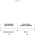
- FIG. 5 is a diagram showing a process of changing system information.
- System information broadcasted by a base station may be changed based on a modification period.
- the base station may broadcast newly changed system information from an occasion when each modification period starts other than some system information. Furthermore, the base station may notify UEs that changed system information will be broadcasted from a next modification period in a previous modification period before the newly changed system information is broadcasted.
- a base station may notify UEs that system information is changed from a next modification period in an n-th modification period 510 right before the (n+1)-th modification period.
- the base station may notify the UEs whether system information has been changed using a paging message.
- the UE needs to receive at least one paging within the modification period in order to identify whether system information has been changed. If a system information change indicator (systemlnfoModification IE) is included in the paging message, this may mean that newly updated system information is transmitted from a next period of the modification period in which the paging is transmitted.
- the system information change indicator (systemlnfoModification IE) may have 1 bit to indicate whether to update system information.
- the base station may increase system information change-related information (may be interchangeably used with a term, such as systemlnfoValueTag or valuetag, hereinafter), included in an SIB1, by 1.
- the system information change-related information (systemlnfoValueTag) may be used for a UE that has camped on again from out-of-coverage to determine whether system information stored in the UE will be identical with now broadcasted system information.
- the UE may determine whether system information has been changed using the paging message or the system information change-related information (systemlnfoValueTag) of the SIB1.
- a DRX cycle is extended to be longer than a maximum value of a modification period in order to reduce consumption power, that is, if second DRX is applied, however, a UE may not receive paging within a modification period. In this case, the UE cannot identify whether system information is newly updated. In particular, if configuration information on a paging message among system information is changed, a problem in that the UE does not subsequently receive a paging message in a modification period may occur. Accordingly, there is a need for a method for solving this problem.
- FIG. 6 is a diagram showing a process of changing system information (SI) when a second DRX cycle is applied.
- SI system information
- a base station may notify a UE that system information (SI) will be changed using paging 611 prior to a system information (SI) change or update (612). As described above, such an operation may be performed based on a modification period 610.
- SI system information
- SI system information
- the base station when the base station transmits the updated system information (updated SI) 612 in a modification period 640, it may notify the UE that system information (SI) will be changed in the next modification period 640 during the modification period 610 prior to a system information (SI) change. Accordingly, the UE needs to identify whether system information (SI) is changed in the next modification period 640 by receiving at least one paging during the modification period 610.
- SI system information
- a UE operating in DRX checks paging every DRX cycle. Accordingly, if the UE operates in second DRX, it cannot receive paging if the paging is transmitted in a second DRX cycle 620, and cannot identify whether to update the system information (630).
- the UE After the second DRX cycle elapses, the UE has to identify whether system information has been changed by receiving paging in the modification period. If system information related to a paging message is changed, however, a problem in that the UE cannot receive a paging message may occur.
- the disclosure describes a method of extending a modification period and a method for a UE to wake up right before DRX timing and to identify cell selection or cell (re)selection and whether system information (SI) has been changed, and proposes a method of selectively applying the method according to a given condition.
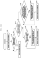
- FIG. 7 is a diagram showing a process of updating system information in a DRX cycle.
- a UE may selectively apply the existing system information update procedure or a new system information update procedure based on a DRX cycle.
- the new system information (SI) update method may mean a method for a UE to wake up right before extended DRX timing and to identify cell selection or cell (re)selection and whether system information (SI) has been changed in addition to a method of providing notification of whether to update the system information (SI) using the existing paging.
- the UE may determine whether a currently applied DRX cycle is greater than a threshold X.
- the threshold X may be pre-determined value or may be received from a base station explicitly. For example, a modification period may be extended to a maximum of 10.24 seconds. Accordingly, the base station may set 10.24 seconds as the threshold X. That is, the base station may set the threshold based on the length of the modification period. Alternatively, the length of the modification period may be determined to be the threshold. In this case, the base station may notify the UE of the threshold X through a system information block (SIB) or dedicated signalling.
- SIB system information block
- the UE performs the existing system information (SI) update procedure at operation S720. That is, the UE may attempt paging reception at DRX timing.
- SI system information
- system information change indicator (systemlnfoModification IE) included in the received paging has a "true” value or is set as true, this provides notification that system information (SI) will be changed in a next modification period.
- SIB2 system information
- the UE may perform a new system information update procedure.
- the UE may wake up right before DRX timing, and may identify a cell to be selected or (re)selected (suitable cell) by performing a cell selection or (re)selection operation. Specifically, the UE may wake up right before DRX timing in an inactive period and perform a cell selection or (re)selection operation.
- the suitable cell to be selected or (re)selected may mean a cell on which the UE camps in order to obtain common service or may mean a cell included in a selected PLMN or a registered PLMN. Alternatively, the suitable cell may mean a cell that the UE has joined or a cell to which the UE's access is not prohibited.
- the UE may perform a system information (SI) validity check by receiving system information (e.g., SIB1) from an identified cell. The UE may perform the SI validity check using system information change-related information (value tag), which is described in detail later.
- SI system information
- the UE may receive updated system information (SI).
- SI system information
- RRC connection establishment is not necessary (e.g., if its own paging record is not present after paging is received)
- SI system information
- a base station may notify a UE whether to update system information (SI) using paging as in the existing system information (SI) update method.
- SI system information
- a new modification period is necessary because the UE applying a second DRX (eDRX) cycle has to receive at least one paging in a modification period.
- FIG. 8 is a diagram showing a method of extending a modification period.
- paging may be received although a very long DRX cycle (second DRX cycle) is applied.
- a modification period may be extended so that at least one piece of DRX timing is included in one modification period 810. That is, the modification period 810 may be configured to be longer than a second DRX cycle 820.
- paging 811 providing notification of a system information (SI) change may be transmitted during the extended modification period.
- SI system information
- a UE may receive the paging at least once (830).
- the modification period value may be provided to the UE through system information (e.g., SIB2).
- SIB2 system information
- signaling overhead in transmitting paging during a modification period may also increase because the modification period has to be extended as a DRX cycle becomes longer.
- a base station and the UE may use two system information (SI) update methods as a new system information update procedure.
- SI system information
- the UE may wake up right before DRX timing, may identify a cell to be selected or (re)selected (suitable cell) by performing a cell selection or (re)selection operation, and may receive system information (SI) from the cell.
- SI system information
- the UE may perform a validity check using system information change-related information included in the system information, and may receive updated system information if the update of system information is necessary.
- the UE may not receive system information (SI).
- SI system information
- the base station may indicate that a system information (SI) update is necessary through paging in an extended modification period, and may update system information (SI) in a next modification period.
- SI system information
- the extended modification period is applied separately from the existing modification period.
- the existing modification period may be referred to as a first modification period
- the extended modification period may be referred to as a second modification period.
- the disclosure proposes a base station operation of selectively using the two methods based on updated system information. Furthermore, the disclosure proposes a UE operation of selectively updating system information according to circumstances.
- FIG. 9 is a diagram showing a method of identifying the update of system information.
- a method of identifying the update of system information through a validity check prior to RRC connection establishment is described with reference to FIG. 9 .
- a UE may perform the method when a second DRX (eDRX) cycle is longer than a modification period.
- eDRX second DRX
- the UE may receive paging during a configured paging time window (PTW) 905 in each second DRX (eDRX) cycle 900.
- a UE operating in the second DRX may perform a DRX operation according to a first cycle during a given period when a second cycle is reached.
- the given period may be called a PTW.
- the reception probability of paging can be increased because the paging is repeatedly received during a given period.
- the UE may receive system information (e.g., SIB1) broadcasted from the cell.
- SIB1 system information
- the UE may identify system information change-related information (value of a value tag) included in the system information, and may determine whether the identified system information change-related information is identical with previously stored system information change information (value tag value) (915). Such an operation may be referred to as an SI validity check (or validity check).
- the UE may receive system information broadcasted from the cell before it performs RRC connection establishment.
- the UE may read the system information (e.g., SIB1) and may not perform an SI validity check.
- SIB1 system information
- a UE may need to successfully decode a received paging message, but may not properly operate if paging configuration information provided as system information is changed.
- FIG. 10 is a diagram showing another method of identifying the update of system information.
- FIG. 10 is a diagram for illustrating a method of indicating whether the update of system information (SI) is necessary by transmitting paging in an extended modification period.
- SI system information
- a UE may identify whether to update system information according to the method.
- the UE may receive paging during a configured PTW (1005) time period in each second DRX (eDRX) cycle 1000.
- eDRX second DRX
- a UE operating in second DRX may perform a DRX operation according to a first cycle during a PTW period.
- the reception probability of paging can be increased by repeatedly the paging during a PTW period.
- system information (SI) may be updated from a given occasion (1010).
- the indicator may indicate that the updated system information (SI) is transmitted from the given occasion.
- a system information change indicator (system I nfoModification-eDRX) for second DRX and a system information change indicator (systemlnfoModification-DRX) for first DRX may be separately managed.
- system information necessary to receive a paging message may be defined as first system information. If a UE operates in second DRX and first system information is updated, the UE may be notified of the update of the first system information by including the system information change indicator (system InfoModification-eDRX) for the second DRX in a paging message and transmitting the paging message. Detailed contents are described later.
- system information change indicator for the first DRX
- system information change indicator for the second DRX
- system information change indicator for the second DRX
- a system information change indicator may mean the second system information change indicator
- system information change indicator (systemInfoModification-eDRX) for the second DRX and the system information change indicator (systemlnfoModification-DRX) for the first DRX may be managed as one.
- the UE may identify that the occasion is present at given intervals, that is, 256 * 10.24 seconds, through a received paging message. This may mean a second modification period (extended modification period).
- the UE may receive a paging message at least once within the PTW period within the given interval.
- a base station needs to include the second system information change indicator (systemlnfoModification-eDRX indicator) in each paging message transmitted during the second modification period (extended modification period).
- the UE may perform an SI validity check 1025.
- the method may have great signaling overhead because the base station has to transmit a paging message, including the second system information change indicator, during the second modification period (extended modification period).
- Method 1 has a problem in that a UE cannot receive a paging message if paging configuration information provided as system information is changed.
- Method 2 has a problem in that signaling overhead may occur. Accordingly, in order to overcome the above-described problems, the disclosure proposes a method for a base station to determine whether to use a method of indicating whether system information (SI) needs to be updated through paging depending on the type of updated system information.
- SI system information
- system information necessary for a UE to receive a paging message may be defined as first system information.
- a paging message is used to indicate whether system information (SI) needs to be update, a paging message has to be transmitted for a long time.
- SI system information
- most of the update of system information may use Method 1. That is, a UE may identify whether to update system information using system information change-related information when a RRC connection is triggered.
- a UE needs to receive a paging message at least in order to determine whether to perform RRC connection establishment. Accordingly, a base station notifies a UE of first system information necessary to receive a paging message only when the first system information is updated through a paging message.
- system information other than first system information may be defined as second system information.
- representative first system information may include paging control channel configuration information (pcch-config IE), which may be included in a system information block (e.g., SIB2) and broadcasted.
- pcch-config IE paging control channel configuration information
- the paging control channel configuration information may include configuration information, such as that of Table 1.
- the default paging cycle (defaultPagingCycle) may indicate a cell-specific paging cycle.
- the paging-related first parameter (nB) is a variable used to derive a paging frame (PF).
- MTC machine type communication
- a base station may repeatedly transmit a machine type physical downlink control channel (MPDCCH) indicative of paging and a paging message in a plurality of narrowbands.
- MPDCCH machine type physical downlink control channel
- Related configuration information may be included in pcch-config.
- a paging-narrowband may be used to indicate a narrowband used for paging.
- the range of a paging-related first parameter (nB value) may be extended by taking into consideration repetition transmission.
- a base station broadcasts that an SI update is necessary using a paging message.
- a base station when subframe bitmap-related information (fdd-DownlinkOrTddSubframeBitmapLC-r13) and hopping-related information (si-HoppingConfigCommon-r13) included in an SIB1 are changed, a base station broadcasts that an SI update is necessary using a paging message.
- fdd-DownlinkOrTddSubframeBitmapLC-r13 may include subframe information which may be used by a UE to which the MTC technology is applied.
- a paging message delivered to an MTC UE is information necessary for the UE to receive a paging message because the message is transmitted only in a subframe.
- si-HoppingConfigCommon-r13 may indicate whether an SI message and a paging message are subjected to frequency hopping (frequency movement when a message is transmitted). If the information is not present, a UE may need to perform blind decoding on an available frequency. Accordingly, the information is information necessary for the UE to receive a paging message.
- FIG. 11A is a diagram showing an operation of an eNB in the disclosure.
- the eNB may determine to update system information at operation S1105. In this case, the eNB may determine to update some of or the entire system information. The eNB may determine to update first system information.
- the eNB may determine whether the eNB supports second DRX (extended DRX cycle).
- the eNB may determine to update system information (SI) according to first DRX (the existing technology) at operation S1115.
- SI system information
- a UE may attempt to receive paging at DRX timing. If a system information change indicator (systemlnfoModification IE) included in the received paging has a "true" value or is set as true, this provides notification that system information (SI) will be changed in a next modification period.
- the UE may receive new system information (SI) in a next modification period using a modification period value obtained from system information (e.g., SIB2).
- SIB2 system information change indicator
- the eNB may determine whether it supports a coverage extension function in the MTC technology at operation S1117.
- the eNB may determine whether changed system information includes at least paging control channel configuration information (pcch-config) at operation S1120.
- pcch-config paging control channel configuration information
- the eNB may transmit a paging message or PDCCH, including a second system information change indicator (or SI update indicator), to the UE in order to notify whether to update the system information (SI) through the paging message at operation S1125.
- a second system information change indicator or SI update indicator
- the eNB may omit operation S1125.
- the eNB may broadcast updated system information in a next second DRX acquisition period (eDRX acquisition period) at operation S1130.
- the eNB may determine whether the changed system information includes at least one of paging channel configuration information (pcch-config), subframe bitmap-related information (fdd-DownlinkOrTddSubframeBitmapLC-r13), and hopping-related information (si-HoppingConfigCommon-r13) at operation S1135.
- paging channel configuration information pcch-config
- subframe bitmap-related information fdd-DownlinkOrTddSubframeBitmapLC-r13
- hopping-related information si-HoppingConfigCommon-r13
- the eNB may transmit a paging message or (M)PDCCH, including a second system information change indicator (SI update indicator), to the UE in order to notify the UE whether to update the system information (SI) through the paging message at operation S1140.
- SI update indicator a second system information change indicator
- the eNB may omit operation S1140.
- the eNB may broadcast the updated system information in a next second DRX acquisition period (eDRX acquisition period) at operation S1145.
- the disclosure proposes a system information (SI) reception method when a UE receives a system information (SI) update indicator or after a given operation in order to minimize the complexity of the UE when system information (SI) is updated.
- SI system information
- a UE When a UE receives an SI update indicator, that is, a second system information change indicator (systemlnfoModification-eDRX), through a paging message, the UE has to receive updated system information from a given occasion.
- the UE will update the entire system information because the UE is unaware that which system information is to be updated and may recognize that system information will be simply updated.
- a UE in which second DRX (eDRX) has been configured receives an SI update indicator, that is, a second system information change indicator (systemlnfoModification-eDRX), through a paging message
- an SI update indicator that is, a second system information change indicator (systemlnfoModification-eDRX)
- the UE updates only an SIB1 and an SIB2 form a given occasion.
- configuration information necessary to receive the paging message is included in the SIB1 and the SIB2.
- the UE that has updated only the SIB1 and SIB2 does not increase the value of system information change-related information (systemlnfoValueTag) by 1 because the entire system information is not updated.
- the UE determines whether to update the system information by comparing stored system information change-related information (systemlnfoValueTag) with system information change-related information included in the SIB1.
- systemlnfoValueTag stored system information change-related information
- the UE updates the entire system information if the system information change-related information included in the updated SIB1 is different from the stored system information change-related information because the value of the stored system information change-related information (systemlnfoValueTag) has not been increased by 1.
- the UE updates only the SIB1 and SIB2. Accordingly, UE complexity occurring because the entire system information is received can be reduced.
- the UE if a UE in which second DRX (eDRX) has been configured performs a cell selection or (re)selection operation prior to the paging reception, the UE omits an SI validity check when RRC connection establishment is performed based on a paging message (when the paging message includes the paging record of the UE).
- eDRX second DRX
- a UE in which second DRX (eDRX) has been configured may also move to a neighbor cell. Accordingly, the UE may change a serving cell through cell selection or (re)selection. When the serving cell is changed, an operation first performed by the UE is to read (receive) system information from the new serving cell. This is for identifying whether the changed serving cell is a suitable cell and TA has been changed. If necessary, a TAU may be necessary, and the UE may perform a TAU procedure.
- the UE may receive a paging message from the cell.
- the UE needs to perform an SI validity check according to a system information (SI) update method in second DRX (eDRX).
- SI system information
- eDRX system information update method
- a UE may avoid the redundant reception of system information occurring due to a standard operation.
- FIG. 11B is a diagram showing another operation of an eNB according to the disclosure.
- the eNB may determine whether it supports second DRX (eDRX) at operation S1150.
- the eNB may broadcast system information at operation S1151. If the eNB supports the second DRX, the eNB may broadcast the system information, including second DRX capability information (eDRX capability), to a UE.
- second DRX capability information eDRX capability
- the eNB may broadcast system information including only first DRX (existing DRX) configuration information at operation S1152. If the eNB does not support the second DRX, a UE may operate according to the first DRX, and detailed contents thereof are omitted.
- first DRX existing DRX
- the eNB may determine whether to update the system information at operation S1153.
- the eNB may determine whether to update the system information including first system information at operation S1154.
- the eNB may transmit a paging message, indicating whether the system information (SI) is to be updated, to the UE at operation S1155.
- the eNB may transmit the paging message, including a system information change indicator, to the UE.
- the eNB may transmit the paging message to the UE during a second modification period longer than a first modification period. Specifically, the eNB may determine whether the second cycle is greater than the length of the first modification period. If the second cycle is greater than the length of the first modification period, the eNB may transmit the paging message to the UE during the second modification period.
- Detailed contents are the same as those described above and are hereinafter omitted.
- the eNB may increase systemlnfoValueTag and systemlnfoValueTagExt values by 1 at operation S1156. Alternatively, the eNB increases the systemlnfoValueTag value by 1. When a wraparound occurs, the eNB may increase systemlnfoValueTagExt by 1.
- the eNB may increase the systemInfoValueTag systemlnfoValueTagExt value, included in system information change-related information, by 1. Alternatively, the eNB increases the systemlnfoValueTag value by 1. When a wraparound occurs, the eNB may increase systemlnfoValueTagExt by 1.
- the eNB may broadcast system information (e.g., SIB1) including the changed system information change-related information (IE value) at operation S1157.
- SIB1 system information
- IE value changed system information change-related information
- the UE may update the first system information based on the system information change indicator included in the paging message, and may determine whether to update the entire system information, including the second system information, based on the system information change-related information included in the first system information.
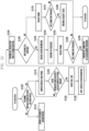
- FIG. 12 is a diagram showing an operation of a UE in the disclosure.
- the UE may determine whether second DRX (eDRX) has been applied at operation S1205.
- the UE may operate according to the existing method at operation S1210. That is, the UE may operate in first DRX in a power saving mode.
- the UE may monitor an (M)PDCCH and paging during a PTW period at operation S1215.
- an eNB may transmit a paging message in a second modification period (extended modification period).
- the UE may compare a second cycle with a first modification period, and may monitor whether a paging message is received in the second modification period if the second cycle is greater than the first modification period.
- the UE may receive a paging message in a PTW period after a second DRX cycle expires.
- the UE may determine whether a system information change indicator (SI update indicator) is included in the (M)PDCCH or the paging message at operation S1220.
- SI update indicator system information change indicator
- the UE may update only an SIB1 and an SIB2 at operation S1225.
- the UE may update only the SIB1 and SIB2 in a second DRX acquisition period (eDRX acquisition period).
- the UE may apply the updated system information (SI) at operation S1230.
- SI system information
- the UE may perform cell (re)selection prior to the paging reception at operation S1235.
- the UE that has performed the cell (re)selection may determine whether it has discovered a new serving cell at operation S1240. That is, the UE may identify whether the selected or (re)selected cell is a new serving cell. In this case, the new serving cell may mean a cell different from a current serving cell.
- the UE may receive system information from the new serving cell at operation S1245. Furthermore, the UE may perform a TAU procedure, if necessary, at operation S1250.
- the UE may receive paging from the new serving cell at operation S1255.
- the UE that has received the paging may determine whether an RRC connection has been triggered at operation S1260.
- the UE may perform an RRC connection establishment procedure at operation S1265.
- an SI validity check procedure may be omitted because the system information has been received in the cell (re)selection operation process.
- the UE may receive paging at operation S1270.
- the UE that has received the paging may determine whether an RRC connection has been triggered at operation S1275.
- the UE may receive an SIB1 from a selected or (re)selected cell at operation S1280, and may perform an SI validity check. Accordingly, the UE may compare stored system information change-related information with stored system information change-related information identified using the SIB1, and may update the system information if the pieces of information are different.
- the UE may receive paging by applying the updated system information at operation S1230.
- the UE that has received the paging may determine whether an RRC connection has been triggered. If the RRC connection has been triggered, the UE may perform a validity check.
- the UE may compare store system information change-related information with stored system information change-related information identified using the received SIB1, and may update the entire system information including the second system information if the pieces of information are different.
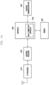
- FIG. 13 is a block diagram of a UE according to the disclosure.
- the UE includes a radio frequency (RF) processor 1310, a baseband processor 1320, a memory 1330, and a controller 1340.
- the RF processor 1310 may perform functions for transmitting/receiving a signal through a radio channel, such as the band conversion and amplification of a signal. That is, the RF processor 1310 may up-convert a baseband signal received from the baseband processor 1320 into an RF band signal, may transmit the RF band signal through an antenna, and may down-convert an RF band signal received through the antenna into a baseband signal.
- a radio frequency (RF) processor 1310 may perform functions for transmitting/receiving a signal through a radio channel, such as the band conversion and amplification of a signal. That is, the RF processor 1310 may up-convert a baseband signal received from the baseband processor 1320 into an RF band signal, may transmit the RF band signal through an antenna, and may down-convert an RF band signal received through the antenna into a
- the RF processor 810 may include a transmission filter, a reception filter, an amplifier, a mixer, an oscillator, a digital to analog convertor (DAC), and an analog to digital convertor (ADC).
- the UE may include multiple antennas.
- the RF processor 810 may include multiple RF chains.
- the RF processor 810 may perform beamforming. For the beamforming, the RF processor 810 may adjust the phase and size of each of signals transmitted and received through multiple antennas or antenna elements.
- the baseband processor 1320 may perform a baseband signal and inter-bit stream conversion function based on the physical layer standard of a system.
- the baseband processor 1320 may generate complex symbols by coding and modulating a transmission bit stream. Furthermore, when data is received, the baseband processor 1320 may reconstruct a reception bit stream from a baseband signal, received from the RF processor 1310, through demodulation and decoding. For example, if an orthogonal frequency division multiplexing (OFDM) scheme is applied, when data is transmitted, the baseband processor 1320 may generate complex symbols by coding and modulating a transmission bit stream, may map the complex symbols to subcarriers, and may then configure OFDM symbols through inverse fast Fourier transform (IFFT) operation and cyclic prefix (CP) insertion.
- OFDM orthogonal frequency division multiplexing
- the baseband processor 1320 may segment a baseband signal, received from the RF processor 1310, in an OFDM symbol unit, may reconstruct signals mapped to subcarriers through fast Fourier transform (FFT) operation, and may reconstruct a reception bit stream through demodulation and decoding.
- the baseband processor 1320 and the RF processor 1310 may transmit and receive signals as described above. Accordingly, the baseband processor 1320 and the RF processor 1310 may be called a transmitter, a receiver, a transceiver or a communication unit.
- at least one of the baseband processor 1320 and the RF processor 1310 may include multiple communication modules in order to support multiple different radio access technologies.
- the baseband processor 1320 and the RF processor 1310 may include different communication modules in order to process signals of different frequency bands.
- the different radio access technologies may include a wireless LAN (e.g., IEEE 802.11), a cellular network (e.g., LTE), etc.
- the different frequency bands may include a super high frequency (SHF) (e.g., 2.5 GHz, 5 GHz) band and a millimeter wave (e.g., 60 GHz) band.
- SHF super high frequency
- the memory 830 may store data, such as a basic program, an application program, and configuration information for the operation of the UE.
- the memory 1330 may store information related to an access node that performs wireless communication using a second radio access technology.
- the memory 1330 may provide stored data in response to a request from the controller 1340.
- the controller 1340 may control an overall operation of the UE.
- the controller 1340 may transmit and receive signals through the baseband processor 1320 and the RF processor 1310.
- the controller 1340 writes data in the memory 1340 and reads data from the memory 1340.
- the controller 1340 may include at least one processor.
- the controller 1340 may include a communication processor (CP) performing control for communication and an application processor (AP) controlling a higher layer, such as an application program.
- CP communication processor
- AP application processor
- the controller 1340 may control the UE to perform the illustrated operations and procedures of the UE.
- the controller 1340 may determine whether second DRX (eDRX) has been applied. If the second DRX (eDRX) has not been applied, the controller 1340 may operate according to the existing method. That is, the controller 1340 may operate as first DRX in a power saving mode.
- the controller 1340 may monitor an (M)PDCCH and paging during a PTW period.
- a base station may transmit a paging message in a second modification period (extended modification period).
- the controller 1340 may compare a second cycle with a first modification period. If the second cycle is greater than the first modification period, the controller may monitor whether a paging message is received the second modification period. Furthermore, the controller 1340 may receive a paging message in a PTW period after the second DRX cycle expires.
- the controller 1340 may determine whether a system information change indicator (SI update indicator) is included in the (M)PDCCH or the paging message.
- SI update indicator system information change indicator
- the controller 1340 may update only an SIB1 and an SIB2.
- the controller 1340 may update only the SIB1 and SIB2 in a second DRX acquisition period (eDRX acquisition period).
- controller 1340 may apply updated system information (SI).
- SI system information
- controller 1340 may perform cell (re)selection prior to the paging reception.
- the controller 1340 may determine whether a new serving cell has been discovered. That is, the UE may identify whether the selected or (re)selected cell is a new serving cell. In this case, the new serving cell may mean a cell different from a current serving cell.
- the controller 1340 may receive system information from the new serving cell. Furthermore, the controller 1340 may perform a TAU procedure, if necessary.
- the controller 1340 may receive paging from the new serving cell.
- the controller 1340 that has received the paging may determine whether an RRC connection has been triggered. If the RRC connection has been triggered, the controller 1340 may perform an RRC connection establishment procedure.
- the controller 1340 may omit an SI validity check procedure because the system information has been received in the above cell (re)selection operation process.
- the controller 1340 may receive paging.
- the controller 1340 that has received the paging may determine whether an RRC connection has been triggered.
- the controller 1340 may receive an SIB1 from a selected or (re)selected cell and perform an SI validity check. Accordingly, the controller 1340 may compare store system information change-related information with stored system information change-related information identified using the received SIB1, and may update the system information if the pieces of information are different.
- the controller 1340 may receive paging by applying the updated system information.
- the controller 1340 that has received the paging may determine whether an RRC connection has been triggered. If the RRC connection has been triggered, the UE may perform a validity check.
- the controller 1340 may compare store system information change-related information with stored system information change-related information identified using a received SIB1, and may update the entire system information, including the second system information, if the pieces of information are different.
- FIG. 14 is a diagram showing the configuration of an eNB according to the disclosure.
- the eNB may include an RF processor 1410, a baseband processor 1420, a backhaul communication unit 1430, a memory 1440 and a controller 1450.
- the RF processor 1410 may perform a function for transmitting/receiving a signal through a radio channel, such as the band conversion and amplification of a signal. That is, the RF processor 1410 may up-convert a baseband signal received from the baseband processor 1420 into an RF band signal, may transmit the RF band signal through an antenna, and may down-convert an RF band signal received through the antenna into a baseband signal.
- the RF processor 1410 may include a transmission filter, a reception filter, an amplifier, a mixer, an oscillator, a DAC, and an ADC.
- the first access node may include multiple antennas.
- the RF processor 1410 may include multiple RF chains.
- the RF processor 1410 may perform beamforming. For the beamforming, the RF processor 1410 may adjust the phase and size of each of signals transmitted and received multiple antennas or antenna elements.
- the baseband processor 1420 may perform a baseband signal and inter-bit stream conversion function based on the physical layer standard of a first radio access technology. For example, when data is transmitted, the baseband processor 1420 may generate complex symbols by coding and modulating a transmission bit stream.
- the baseband processor 1420 may reconstruct a reception bit stream from a baseband signal received from the RF processor 1410 through demodulation and decoding. For example, if the OFDM scheme is applied, when data is transmitted, the baseband processor 1420 may generate complex symbols by coding and modulating a transmission bit stream, may map the complex symbols to subcarriers, and may configure OFDM symbols through IFFT operation and CP insertion. Furthermore, when data is received, the baseband processor 1420 may segment a baseband signal received from the RF processor 1410 in an OFDM symbol unit, may reconstruct signals mapped to subcarriers through FFT operation, and may then reconstruct a reception bit stream through demodulation and decoding.
- the baseband processor 1420 and the RF processor 1410 may transmit and receive signals as described above. Accordingly, the baseband processor 1420 and the RF processor 1410 may be called a transmitter, a receiver, a transceiver, a backhaul communication unit or a wireless communication unit.
- the backhaul communication unit 1430 may provide an interface for performing communication with other nodes within a network. That is, the backhaul communication unit 1430 may convert a bit stream, transmitted from a main eNB to other nodes, for example, an assistant eNB or a core network, into a physical signal, and may convert a physical signal, received from the other nodes, into a bit stream.
- the memory 1440 may store data, such as a basic program, an application program, and configuration information for the operation of the main eNB. Specifically, the memory 1440 may store information on a bearer allocated to an accessed UE and measurement results reported by an accessed UE. Furthermore, the memory 1440 may store information, that is, a criterion by which whether to provide a UE with multi-connectivity or whether to stop multi-connectivity is determined. Furthermore, the memory 1440 may provide stored data in response to a request from the controller 1450.
- the controller 1450 may control an overall operation of the main eNB. For example, the controller 1450 may transmit and receive signals through the baseband processor 1420 and the RF processor 1410 or through the backhaul communication unit 1430. Furthermore, the controller 1450 writes data in the memory 1440 and reads data from the memory 1440. To this end, the controller 1450 may include at least one processor.
- the controller 1450 may include a multi-connectivity controller 1452 performing control for providing multi-connectivity to a UE.
- the controller 1450 may control the main eNB to perform the illustrated operations and procedures of the eNB.
- the controller 1450 may determine whether the eNB supports second DRX (eDRX). The controller 1450 may broadcast system information. If the controller 1450 supports the second DRX, the controller 1450 may broadcast the system information, including second DRX capability information (eDRX capability), to a UE.
- eDRX capability second DRX capability information
- the controller 1450 may broadcast the system information including only first DRX (existing DRX) configuration information. If the controller 1450 does not support the second DRX, a UE may operate according to the first DRX, and detailed contents thereof are omitted.
- the controller 1450 may determine whether to update the system information.
- the controller 1450 may determine whether to update the system information.
- the controller 1450 may transmit a paging message, indicating whether the system information (SI) is to be updated, to the UE.
- the controller 1450 may transmit the paging message, including a system information change indicator, to the UE.
- the controller 1450 may transmit the paging message to the UE during a second modification period longer than a first modification period. Specifically, the controller 1450 may determine whether the second cycle is greater than the length of the first modification period. If the second cycle is greater than the length of the first modification period, the controller 1450 may transmit the paging message to the UE during the second modification period. Detailed contents are the same as those described above and are hereinafter omitted.
- the controller 1450 may increase systemlnfoValueTag and systemlnfoValueTagExt values by 1. Alternatively, the controller 1450 increases the systemlnfoValueTag value by 1. When a wraparound occurs, the controller 1450 may increase systemlnfoValueTagExt by 1.
- the controller 1450 may increase the systemInfoValueTag systemlnfoValueTagExt value, included in system information change-related information, by 1. Alternatively, the controller 1450 increases the systemlnfoValueTag value by 1. When a wraparound occurs, the controller 1450 may increase systemlnfoValueTagExt by 1.
- the controller 1450 may broadcast system information (e.g., SIB1) including the changed system information change-related information (IE value).
- system information e.g., SIB1
- IE value changed system information change-related information
- the UE may update the first system information based on the system information change indicator included in the paging message, and may determine whether to update the entire system information, including the second system information, based on the system information change-related information included in the first system information.
- the controller 1450 may determine whether the eNB supports a coverage extension function in the MTC technology.
- the controller 1450 may determine whether the changed system information includes at least paging control channel configuration information (pcch-config).
- the controller 1450 may transmit a paging message or PDCCH, including a system information change indicator (or SI update indicator), to the UE in order to notify the UE whether to update the SI through the paging message.
- a system information change indicator or SI update indicator
- the process may be omitted.
- the controller 1450 may determine whether the changed system information includes at least one of paging channel configuration information (pcch-config), subframe bitmap-related information (fdd-DownlinkOrTddSubframeBitmapLC-r13), and hopping-related information (si-HoppingConfigCommon-r13).
- pcch-config paging channel configuration information
- subframe bitmap-related information fdd-DownlinkOrTddSubframeBitmapLC-r13
- hopping-related information si-HoppingConfigCommon-r13
- the controller 1450 may transmit a paging message or (M)PDCCH, including a system information change indicator (SI update indicator), to the UE in order to notify the UE whether to update the SI through the paging message.
- SI update indicator system information change indicator
- the controller 1450 may omit the process.
Landscapes
- Engineering & Computer Science (AREA)
- Computer Networks & Wireless Communication (AREA)
- Signal Processing (AREA)
- Computer Security & Cryptography (AREA)
- Mobile Radio Communication Systems (AREA)
Claims (6)
- Verfahren, das von einem Endgerät (301), in dem ein erweiterter diskontinuierlicher Empfang, eDRX, konfiguriert ist, in einem Kommunikationssystem durchgeführt wird, wobei das Verfahren umfasst:Empfangen einer ersten Funkrufnachricht von einer Basisstation (303) in einer erweiterten Änderungsperiode;Identifizieren, ob ein Systeminformationsänderungsindikator, der anzeigt, dass eine erste Systeminformation unter den gesamten Systeminformationen geändert werden soll, in der ersten Funkrufnachricht enthalten ist, wobei die erste Systeminformation nur einen Systeminformationsblock 1, SIB1, und einen Systeminformationsblock 2, SIB2, enthält;Empfangen einer geänderten ersten Systeminformation von der Basisstation (303) in einer nächsten erweiterten Änderungsperiode für den Fall, dass der Systeminformationsänderungsindikator in der ersten Funkrufnachricht enthalten ist, wobei das Endgerät einen Wert einer ersten Wertmarke, die in dem Endgerät (301) gespeichert ist, nicht erhöht, für den Fall, dass nur die erste Systeminformation auf die geänderte erste Systeminformation unter den gesamten Systeminformationen aktualisiert wird;Empfangen einer zweiten Funkrufnachricht von der Basisstation (303) für einen Funkressourcensteuerungs-, RRC,-Verbindungsaufbau auf der Grundlage der geänderten ersten Systeminformation;Vergleichen des Wertes der ersten Wertmarke, die im Endgerät gespeichert ist, mit einem Wert einer zweiten Wertmarke, die im SIB 1 enthalten ist, für den Fall, dass der RRCVerbindungsaufbau auf der Grundlage der zweiten Funkrufnachricht ausgelöst wird; undAktualisieren der gesamten Systeminformationen, falls sich der Wert der ersten Wertmarke vom Wert der zweiten Wertmarke unterscheidet.
- Verfahren nach Anspruch 1, wobei der Empfang der zweiten Funkrufnachricht umfasst:Empfangen der zweiten Funkrufnachricht von der Basisstation (303) auf der Grundlage der geänderten ersten Systeminformation, falls eine bedienende Zelle nicht geändert wird; undIdentifizieren, dass der RRC-Verbindungsaufbau ausgelöst wurde, falls die zweite Funkrufnachricht einen Funkrufeintrag des Endgeräts enthält.
- Verfahren nach Anspruch 1, wobei der Empfang der ersten Funkrufnachricht umfasst:Bestimmen, ob ein Zyklus des eDRX größer ist als die Länge einer Änderungsperiode; undEmpfangen der ersten Funkrufnachricht von der Basisstation (303) in der verlängerten Änderungsperiode, wenn der Zyklus des eDRX größer ist als die Länge der Änderungsperiode.
- Endgerät (301), in dem ein erweiterter diskontinuierlicher Empfang, eDRX, konfiguriert ist, in einem Kommunikationssystem, wobei das Endgerät (301) umfasst:einen Transceiver; undeine Steuerung, die mit dem Transceiver gekoppelt und konfiguriert ist, um:von einer Basisstation (303) eine erste Funkrufnachricht in einer erweiterten Änderungszeitperiode zu empfangen,zu identifizieren, ob ein Systeminformationsänderungsindikator, der anzeigt, dass eine erste Systeminformation unter den gesamten Systeminformationen geändert werden soll, in der ersten Funkrufnachricht enthalten ist, wobei die erste Systeminformation nur einen Systeminformationsblock 1, SIB 1, und einen Systeminformationsblock 2, SIB2, enthält,Empfangen einer geänderten ersten Systeminformation von der Basisstation (303) in einer nächsten erweiterten Änderungsperiode für den Fall, dass der Systeminformationsänderungsindikator in der ersten Funkrufnachricht enthalten ist, wobei das Endgerät einen Wert einer ersten Wertmarke, die in dem Endgerät (301) gespeichert ist, nicht erhöht, für den Fall, dass nur die erste Systeminformation auf die geänderte erste Systeminformation unter den gesamten Systeminformationen aktualisiert wird,von der Basisstation (303) eine zweite Funkrufnachricht für einen Funkressourcensteuerungs-, RRC,-Verbindungsaufbau auf der Grundlage der geänderten ersten Systeminformation zu empfangen,den Wert der ersten Wertmarke, die im Endgerät gespeichert ist, mit einem Wert einer zweiten Wertmarke, die im SIB 1 enthalten ist, zu vergleichen, für den Fall, dass der RRC-Verbindungsaufbau auf der Grundlage der zweiten Funkrufnachricht ausgelöst wird, unddie gesamten Systeminformationen zu aktualisieren, falls sich der Wert der ersten Wertmarke vom Wert der zweiten Wertmarke unterscheidet.
- Endgerät (301) nach Anspruch 4, wobei die Steuerung konfiguriert ist, um:die zweite Funkrufnachricht von der Basisstation (303) auf der Grundlage der geänderten ersten Systeminformation zu empfangen, falls eine bedienende Zelle nicht geändert wird, undzu identifizieren, dass der RRC-Verbindungsaufbau ausgelöst wurde, falls die zweite Funkrufnachricht einen Funlaufeintrag des Endgeräts enthält.
- Endgerät (301) nach Anspruch 4, wobei die Steuerung konfiguriert ist, um:zu bestimmen, ob ein Zyklus des eDRX größer ist als die Länge einer Änderungsperiode; undvon der Basisstation (303) die erste Funkrufnachricht in der verlängerten Änderungsperiode zu empfangen, wenn der Zyklus des eDRX größer ist als die Länge der Änderungsperiode.
Applications Claiming Priority (2)
| Application Number | Priority Date | Filing Date | Title |
|---|---|---|---|
| KR1020160118401A KR102501931B1 (ko) | 2016-09-13 | 2016-09-13 | 무선 통신 시스템에서 시스템 정보 갱신 방법 및 장치 |
| PCT/KR2017/010003 WO2018052233A1 (ko) | 2016-09-13 | 2017-09-12 | 무선 통신 시스템에서 시스템 정보 갱신 방법 및 장치 |
Publications (3)
| Publication Number | Publication Date |
|---|---|
| EP3487259A1 EP3487259A1 (de) | 2019-05-22 |
| EP3487259A4 EP3487259A4 (de) | 2019-05-29 |
| EP3487259B1 true EP3487259B1 (de) | 2023-11-01 |
Family
ID=61620049
Family Applications (1)
| Application Number | Title | Priority Date | Filing Date |
|---|---|---|---|
| EP17851107.7A Active EP3487259B1 (de) | 2016-09-13 | 2017-09-12 | Verfahren und vorrichtung zur aktualisierung von systeminformationen in einem drahtloskommunikationssystem |
Country Status (4)
| Country | Link |
|---|---|
| US (1) | US11032794B2 (de) |
| EP (1) | EP3487259B1 (de) |
| KR (1) | KR102501931B1 (de) |
| WO (1) | WO2018052233A1 (de) |
Families Citing this family (15)
| Publication number | Priority date | Publication date | Assignee | Title |
|---|---|---|---|---|
| CN108632995B (zh) * | 2017-01-24 | 2022-04-15 | 中兴通讯股份有限公司 | 一种寻呼优化的方法和装置 |
| CN118118973A (zh) * | 2017-05-05 | 2024-05-31 | 中兴通讯股份有限公司 | 消息传输方法及装置 |
| US10560916B2 (en) * | 2017-09-30 | 2020-02-11 | Brian A. Stearmer | Paired-timing connectivity event handling in a wireless communications network |
| KR102455586B1 (ko) * | 2018-03-29 | 2022-10-17 | 삼성전자주식회사 | 무선 통신 시스템에서 불연속 수신을 수행하기 위한 방법 및 장치 |
| JP7076533B2 (ja) * | 2018-04-06 | 2022-05-27 | 京セラ株式会社 | 無線通信装置及びその制御方法 |
| US10841898B2 (en) * | 2018-07-18 | 2020-11-17 | Acer Incorporated | Method of receiving paging messages for UE and UE using the same |
| WO2021229478A1 (en) * | 2020-05-13 | 2021-11-18 | Nokia Technologies Oy | System information acquisition for reduced capability nr devices |
| US11696359B2 (en) | 2020-05-18 | 2023-07-04 | Qualcomm Incoporated | Override of default base station discontinuous reception cycle for individual user equipment |
| CN114640952B (zh) * | 2020-12-15 | 2023-11-03 | 上海华为技术有限公司 | 消息处理方法、终端和网络设备 |
| CN116235575B (zh) * | 2020-12-29 | 2025-04-01 | Oppo广东移动通信有限公司 | 无线通信的方法、终端设备和网络设备 |
| WO2022141598A1 (zh) * | 2020-12-31 | 2022-07-07 | 北京小米移动软件有限公司 | 上行定时提前量确定、公共定时相关信息广播方法和装置 |
| WO2022188044A1 (zh) * | 2021-03-09 | 2022-09-15 | 北京小米移动软件有限公司 | 多连接下的通信方法和通信装置 |
| KR102570678B1 (ko) | 2021-10-18 | 2023-08-25 | 주식회사 블랙핀 | 무선 이동 통신 시스템에서 인액티브 상태의 단말이 시스템 정보 업데이트를 수행하는 방법 및 장치 |
| TWI801075B (zh) * | 2022-01-04 | 2023-05-01 | 中華電信股份有限公司 | 為用戶設備配置不連續接收的方法和基地台 |
| US20250031189A1 (en) * | 2022-01-11 | 2025-01-23 | Lg Electronics Inc. | Method and device for transmitting and receiving wireless sig-nals in wireless communication system |
Family Cites Families (18)
| Publication number | Priority date | Publication date | Assignee | Title |
|---|---|---|---|---|
| US8180335B2 (en) * | 2008-01-11 | 2012-05-15 | Qualcomm Incorporated | System information modification notification and detection in wireless communications |
| US8804546B2 (en) * | 2008-06-13 | 2014-08-12 | Qualcomm Incorporated | Method and apparatus for managing interaction between DRX cycles and paging cycles |
| US8843115B2 (en) * | 2008-06-23 | 2014-09-23 | Qualcomm Incorporated | Method and apparatus for managing system information modification in a wireless communication system |
| US9603097B2 (en) | 2009-06-29 | 2017-03-21 | Qualcomm Incorporated | Device, method, and apparatus for offline discontinuous reception (DRX) processing with online triggers in cellular systems |
| US20120276933A1 (en) * | 2011-04-28 | 2012-11-01 | Renesas Mobile Corporation | Detecting change in system information |
| CN104105111B (zh) * | 2013-04-02 | 2017-11-21 | 电信科学技术研究院 | 一种激活时刻的计算方法及装置 |
| WO2014165614A2 (en) * | 2013-04-03 | 2014-10-09 | Motorola Mobility Llc | Methods and devices for cell discovery |
| US9497682B2 (en) | 2013-06-07 | 2016-11-15 | Intel Corporation | Central processing unit and methods for supporting coordinated multipoint transmission in an LTE network |
| KR102182517B1 (ko) | 2013-08-02 | 2020-11-24 | 삼성전자 주식회사 | 이동 통신 시스템에서 시스템 정보와 페이징을 수신하는 방법 및 장치 |
| WO2015021643A1 (en) * | 2013-08-16 | 2015-02-19 | Nokia Siemens Networks Oy | Method and apparatus |
| ES2585937T3 (es) | 2013-10-08 | 2016-10-10 | Telefónica, S.A. | Procedimiento, sistema y dispositivos para mejorar la recepción discontinua en redes de comunicación inalámbrica |
| US10440661B2 (en) * | 2014-08-06 | 2019-10-08 | Quacomm Incorporated | RAN procedures for extended discontinuous reception (DRX) |
| US9763172B2 (en) | 2014-08-06 | 2017-09-12 | Qualcomm Incorporated | Idle-mode enhancements for extended idle discontinuous reception (EI-DRX) |
| EP3247153A4 (de) * | 2015-01-15 | 2018-08-29 | Mitsubishi Electric Corporation | Kommunikationssystem |
| US10616822B2 (en) * | 2015-02-10 | 2020-04-07 | Qualcomm Incorporated | System information updating |
| CN107637142B (zh) * | 2015-04-03 | 2021-11-16 | 交互数字专利控股公司 | 用于使用扩展drx的系统增强 |
| WO2016186696A1 (en) * | 2015-05-21 | 2016-11-24 | Intel Corporation | Transmitting system information change notifications to mtc devices |
| US10028329B2 (en) * | 2015-11-04 | 2018-07-17 | Qualcomm Incorporated | System information change notification for extended discontinuous reception |
-
2016
- 2016-09-13 KR KR1020160118401A patent/KR102501931B1/ko active Active
-
2017
- 2017-09-12 EP EP17851107.7A patent/EP3487259B1/de active Active
- 2017-09-12 US US16/332,504 patent/US11032794B2/en active Active
- 2017-09-12 WO PCT/KR2017/010003 patent/WO2018052233A1/ko not_active Ceased
Also Published As
| Publication number | Publication date |
|---|---|
| US11032794B2 (en) | 2021-06-08 |
| KR102501931B1 (ko) | 2023-02-21 |
| WO2018052233A1 (ko) | 2018-03-22 |
| EP3487259A1 (de) | 2019-05-22 |
| EP3487259A4 (de) | 2019-05-29 |
| KR20180029799A (ko) | 2018-03-21 |
| US20190223153A1 (en) | 2019-07-18 |
Similar Documents
| Publication | Publication Date | Title |
|---|---|---|
| EP3487259B1 (de) | Verfahren und vorrichtung zur aktualisierung von systeminformationen in einem drahtloskommunikationssystem | |
| US11979831B2 (en) | Method and apparatus for applying discontinuous reception mode in wireless communication system | |
| US12238679B2 (en) | Method and device for paging transmission and reception of terminal supporting multiple sims in next-generation mobile communication system | |
| KR102859936B1 (ko) | 무선 통신 시스템에서 복수의 빔을 통해 신호를 송수신하는 방법 및 장치 | |
| US11838852B2 (en) | Method and apparatus for cell barring in wireless communication system | |
| EP3879916B1 (de) | Verfahren und vorrichtung zur v2x-kommunikation in einem mobilkommunikationssystem der nächsten generation | |
| KR102898485B1 (ko) | 무선 통신 시스템에서 주파수 측정 방법 및 장치 | |
| EP3796744A1 (de) | Verfahren und vorrichtung zur unterstützung einer doppelten verbindung des rrc-inaktivierungsmodus in einem mobilen kommunikationssystem der nächsten generation | |
| EP3905838A1 (de) | Verfahren und vorrichtung zur aktivierung und deaktivierung von by-links zur reduzierung des leistungsverbrauchs in einem mobilkommunikationssystem der nächsten generation | |
| US11316652B2 (en) | Method and apparatus for controlling partial frequency band in wireless communication system | |
| US10554282B2 (en) | Method and device for determining rank-related information in wireless communication system | |
| CN113545131B (zh) | 用于在下一代无线通信系统中在空闲模式下重选小区时更新要测量的小区列表的方法和装置 | |
| US20220279427A1 (en) | Method and device for measurement in wireless communication system | |
| US20230124420A1 (en) | Method and device for supporting continuity of broadcast service in wireless communication system | |
| CN110720234A (zh) | 在下一代移动通信系统中配置pdcp设备和sdap设备的方法和装置 | |
| EP4102916A1 (de) | Phr-auslösungsverfahren zur aufnahme eines ruhenden bandbreitenteils in einem mobilkommunikationssystem der nächsten generation, phr-konfigurationsverfahren und vorrichtung | |
| US11197340B2 (en) | Method and apparatus for setting discontinuous reception value in wireless communication system | |
| US12328782B2 (en) | Method and apparatus for supporting dual connectivity for multi-USIM UE in next-generation mobile communication system | |
| US12213098B2 (en) | Method and apparatus for transmitting user data through paging message in mobile communication system | |
| US11641637B2 (en) | Method and apparatus for supporting paging in next generation mobile communication system | |
| KR20230102170A (ko) | 차세대 이동통신 시스템에서 시스템 정보 변경에 관한 방법 및 장치 | |
| US20220030409A1 (en) | Method and apparatus for transmitting and receiving data in wireless communication system | |
| US20250063424A1 (en) | Method and apparatus for processing mac control information in wireless communication system | |
| KR20220052244A (ko) | 차세대 이동 통신 시스템에서 intra-band UL CA를 고려한 Uplink Tx direct current location을 보고하는 방법 및 장치 | |
| KR20230021515A (ko) | 사설망에서 시스템 정보의 유효성을 판단하는 방법 및 장치 |
Legal Events
| Date | Code | Title | Description |
|---|---|---|---|
| STAA | Information on the status of an ep patent application or granted ep patent |
Free format text: STATUS: THE INTERNATIONAL PUBLICATION HAS BEEN MADE |
|
| PUAI | Public reference made under article 153(3) epc to a published international application that has entered the european phase |
Free format text: ORIGINAL CODE: 0009012 |
|
| STAA | Information on the status of an ep patent application or granted ep patent |
Free format text: STATUS: REQUEST FOR EXAMINATION WAS MADE |
|
| 17P | Request for examination filed |
Effective date: 20190215 |
|
| AK | Designated contracting states |
Kind code of ref document: A1 Designated state(s): AL AT BE BG CH CY CZ DE DK EE ES FI FR GB GR HR HU IE IS IT LI LT LU LV MC MK MT NL NO PL PT RO RS SE SI SK SM TR |
|
| AX | Request for extension of the european patent |
Extension state: BA ME |
|
| A4 | Supplementary search report drawn up and despatched |
Effective date: 20190430 |
|
| RIC1 | Information provided on ipc code assigned before grant |
Ipc: H04W 76/20 20180101AFI20190424BHEP |
|
| DAV | Request for validation of the european patent (deleted) | ||
| DAX | Request for extension of the european patent (deleted) | ||
| STAA | Information on the status of an ep patent application or granted ep patent |
Free format text: STATUS: EXAMINATION IS IN PROGRESS |
|
| 17Q | First examination report despatched |
Effective date: 20200402 |
|
| REG | Reference to a national code |
Ref country code: DE Ref legal event code: R079 Free format text: PREVIOUS MAIN CLASS: H04W0076200000 Ipc: H04W0048120000 Ref document number: 602017076116 Country of ref document: DE |
|
| GRAP | Despatch of communication of intention to grant a patent |
Free format text: ORIGINAL CODE: EPIDOSNIGR1 |
|
| STAA | Information on the status of an ep patent application or granted ep patent |
Free format text: STATUS: GRANT OF PATENT IS INTENDED |
|
| RIC1 | Information provided on ipc code assigned before grant |
Ipc: H04W 68/00 20090101ALN20230602BHEP Ipc: H04W 48/12 20090101AFI20230602BHEP |
|
| INTG | Intention to grant announced |
Effective date: 20230620 |
|
| RIC1 | Information provided on ipc code assigned before grant |
Ipc: H04W 68/00 20090101ALN20230612BHEP Ipc: H04W 48/12 20090101AFI20230612BHEP |
|
| GRAS | Grant fee paid |
Free format text: ORIGINAL CODE: EPIDOSNIGR3 |
|
| GRAA | (expected) grant |
Free format text: ORIGINAL CODE: 0009210 |
|
| STAA | Information on the status of an ep patent application or granted ep patent |
Free format text: STATUS: THE PATENT HAS BEEN GRANTED |
|
| AK | Designated contracting states |
Kind code of ref document: B1 Designated state(s): AL AT BE BG CH CY CZ DE DK EE ES FI FR GB GR HR HU IE IS IT LI LT LU LV MC MK MT NL NO PL PT RO RS SE SI SK SM TR |
|
| REG | Reference to a national code |
Ref country code: GB Ref legal event code: FG4D |
|
| REG | Reference to a national code |
Ref country code: CH Ref legal event code: EP |
|
| REG | Reference to a national code |
Ref country code: IE Ref legal event code: FG4D |
|
| REG | Reference to a national code |
Ref country code: DE Ref legal event code: R096 Ref document number: 602017076116 Country of ref document: DE |
|
| REG | Reference to a national code |
Ref country code: LT Ref legal event code: MG9D |
|
| REG | Reference to a national code |
Ref country code: NL Ref legal event code: MP Effective date: 20231101 |
|
| PG25 | Lapsed in a contracting state [announced via postgrant information from national office to epo] |
Ref country code: GR Free format text: LAPSE BECAUSE OF FAILURE TO SUBMIT A TRANSLATION OF THE DESCRIPTION OR TO PAY THE FEE WITHIN THE PRESCRIBED TIME-LIMIT Effective date: 20240202 |
|
| PG25 | Lapsed in a contracting state [announced via postgrant information from national office to epo] |
Ref country code: IS Free format text: LAPSE BECAUSE OF FAILURE TO SUBMIT A TRANSLATION OF THE DESCRIPTION OR TO PAY THE FEE WITHIN THE PRESCRIBED TIME-LIMIT Effective date: 20240301 |
|
| PG25 | Lapsed in a contracting state [announced via postgrant information from national office to epo] |
Ref country code: LT Free format text: LAPSE BECAUSE OF FAILURE TO SUBMIT A TRANSLATION OF THE DESCRIPTION OR TO PAY THE FEE WITHIN THE PRESCRIBED TIME-LIMIT Effective date: 20231101 |
|
| REG | Reference to a national code |
Ref country code: AT Ref legal event code: MK05 Ref document number: 1628652 Country of ref document: AT Kind code of ref document: T Effective date: 20231101 |
|
| PG25 | Lapsed in a contracting state [announced via postgrant information from national office to epo] |
Ref country code: NL Free format text: LAPSE BECAUSE OF FAILURE TO SUBMIT A TRANSLATION OF THE DESCRIPTION OR TO PAY THE FEE WITHIN THE PRESCRIBED TIME-LIMIT Effective date: 20231101 |
|
| PG25 | Lapsed in a contracting state [announced via postgrant information from national office to epo] |
Ref country code: AT Free format text: LAPSE BECAUSE OF FAILURE TO SUBMIT A TRANSLATION OF THE DESCRIPTION OR TO PAY THE FEE WITHIN THE PRESCRIBED TIME-LIMIT Effective date: 20231101 |
|
| PG25 | Lapsed in a contracting state [announced via postgrant information from national office to epo] |
Ref country code: ES Free format text: LAPSE BECAUSE OF FAILURE TO SUBMIT A TRANSLATION OF THE DESCRIPTION OR TO PAY THE FEE WITHIN THE PRESCRIBED TIME-LIMIT Effective date: 20231101 |
|
| PG25 | Lapsed in a contracting state [announced via postgrant information from national office to epo] |
Ref country code: NL Free format text: LAPSE BECAUSE OF FAILURE TO SUBMIT A TRANSLATION OF THE DESCRIPTION OR TO PAY THE FEE WITHIN THE PRESCRIBED TIME-LIMIT Effective date: 20231101 Ref country code: LT Free format text: LAPSE BECAUSE OF FAILURE TO SUBMIT A TRANSLATION OF THE DESCRIPTION OR TO PAY THE FEE WITHIN THE PRESCRIBED TIME-LIMIT Effective date: 20231101 Ref country code: IS Free format text: LAPSE BECAUSE OF FAILURE TO SUBMIT A TRANSLATION OF THE DESCRIPTION OR TO PAY THE FEE WITHIN THE PRESCRIBED TIME-LIMIT Effective date: 20240301 Ref country code: GR Free format text: LAPSE BECAUSE OF FAILURE TO SUBMIT A TRANSLATION OF THE DESCRIPTION OR TO PAY THE FEE WITHIN THE PRESCRIBED TIME-LIMIT Effective date: 20240202 Ref country code: ES Free format text: LAPSE BECAUSE OF FAILURE TO SUBMIT A TRANSLATION OF THE DESCRIPTION OR TO PAY THE FEE WITHIN THE PRESCRIBED TIME-LIMIT Effective date: 20231101 Ref country code: BG Free format text: LAPSE BECAUSE OF FAILURE TO SUBMIT A TRANSLATION OF THE DESCRIPTION OR TO PAY THE FEE WITHIN THE PRESCRIBED TIME-LIMIT Effective date: 20240201 Ref country code: AT Free format text: LAPSE BECAUSE OF FAILURE TO SUBMIT A TRANSLATION OF THE DESCRIPTION OR TO PAY THE FEE WITHIN THE PRESCRIBED TIME-LIMIT Effective date: 20231101 Ref country code: PT Free format text: LAPSE BECAUSE OF FAILURE TO SUBMIT A TRANSLATION OF THE DESCRIPTION OR TO PAY THE FEE WITHIN THE PRESCRIBED TIME-LIMIT Effective date: 20240301 |
|
| PG25 | Lapsed in a contracting state [announced via postgrant information from national office to epo] |
Ref country code: SE Free format text: LAPSE BECAUSE OF FAILURE TO SUBMIT A TRANSLATION OF THE DESCRIPTION OR TO PAY THE FEE WITHIN THE PRESCRIBED TIME-LIMIT Effective date: 20231101 Ref country code: RS Free format text: LAPSE BECAUSE OF FAILURE TO SUBMIT A TRANSLATION OF THE DESCRIPTION OR TO PAY THE FEE WITHIN THE PRESCRIBED TIME-LIMIT Effective date: 20231101 Ref country code: PL Free format text: LAPSE BECAUSE OF FAILURE TO SUBMIT A TRANSLATION OF THE DESCRIPTION OR TO PAY THE FEE WITHIN THE PRESCRIBED TIME-LIMIT Effective date: 20231101 Ref country code: NO Free format text: LAPSE BECAUSE OF FAILURE TO SUBMIT A TRANSLATION OF THE DESCRIPTION OR TO PAY THE FEE WITHIN THE PRESCRIBED TIME-LIMIT Effective date: 20240201 Ref country code: LV Free format text: LAPSE BECAUSE OF FAILURE TO SUBMIT A TRANSLATION OF THE DESCRIPTION OR TO PAY THE FEE WITHIN THE PRESCRIBED TIME-LIMIT Effective date: 20231101 Ref country code: HR Free format text: LAPSE BECAUSE OF FAILURE TO SUBMIT A TRANSLATION OF THE DESCRIPTION OR TO PAY THE FEE WITHIN THE PRESCRIBED TIME-LIMIT Effective date: 20231101 |
|
| PG25 | Lapsed in a contracting state [announced via postgrant information from national office to epo] |
Ref country code: DK Free format text: LAPSE BECAUSE OF FAILURE TO SUBMIT A TRANSLATION OF THE DESCRIPTION OR TO PAY THE FEE WITHIN THE PRESCRIBED TIME-LIMIT Effective date: 20231101 |
|
| PG25 | Lapsed in a contracting state [announced via postgrant information from national office to epo] |
Ref country code: CZ Free format text: LAPSE BECAUSE OF FAILURE TO SUBMIT A TRANSLATION OF THE DESCRIPTION OR TO PAY THE FEE WITHIN THE PRESCRIBED TIME-LIMIT Effective date: 20231101 |
|
| PG25 | Lapsed in a contracting state [announced via postgrant information from national office to epo] |
Ref country code: SK Free format text: LAPSE BECAUSE OF FAILURE TO SUBMIT A TRANSLATION OF THE DESCRIPTION OR TO PAY THE FEE WITHIN THE PRESCRIBED TIME-LIMIT Effective date: 20231101 |
|
| PG25 | Lapsed in a contracting state [announced via postgrant information from national office to epo] |
Ref country code: SM Free format text: LAPSE BECAUSE OF FAILURE TO SUBMIT A TRANSLATION OF THE DESCRIPTION OR TO PAY THE FEE WITHIN THE PRESCRIBED TIME-LIMIT Effective date: 20231101 Ref country code: SK Free format text: LAPSE BECAUSE OF FAILURE TO SUBMIT A TRANSLATION OF THE DESCRIPTION OR TO PAY THE FEE WITHIN THE PRESCRIBED TIME-LIMIT Effective date: 20231101 Ref country code: IT Free format text: LAPSE BECAUSE OF FAILURE TO SUBMIT A TRANSLATION OF THE DESCRIPTION OR TO PAY THE FEE WITHIN THE PRESCRIBED TIME-LIMIT Effective date: 20231101 Ref country code: EE Free format text: LAPSE BECAUSE OF FAILURE TO SUBMIT A TRANSLATION OF THE DESCRIPTION OR TO PAY THE FEE WITHIN THE PRESCRIBED TIME-LIMIT Effective date: 20231101 Ref country code: DK Free format text: LAPSE BECAUSE OF FAILURE TO SUBMIT A TRANSLATION OF THE DESCRIPTION OR TO PAY THE FEE WITHIN THE PRESCRIBED TIME-LIMIT Effective date: 20231101 Ref country code: CZ Free format text: LAPSE BECAUSE OF FAILURE TO SUBMIT A TRANSLATION OF THE DESCRIPTION OR TO PAY THE FEE WITHIN THE PRESCRIBED TIME-LIMIT Effective date: 20231101 |
|
| REG | Reference to a national code |
Ref country code: DE Ref legal event code: R097 Ref document number: 602017076116 Country of ref document: DE |
|
| PLBE | No opposition filed within time limit |
Free format text: ORIGINAL CODE: 0009261 |
|
| STAA | Information on the status of an ep patent application or granted ep patent |
Free format text: STATUS: NO OPPOSITION FILED WITHIN TIME LIMIT |
|
| 26N | No opposition filed |
Effective date: 20240802 |
|
| PGFP | Annual fee paid to national office [announced via postgrant information from national office to epo] |
Ref country code: GB Payment date: 20240822 Year of fee payment: 8 |
|
| PG25 | Lapsed in a contracting state [announced via postgrant information from national office to epo] |
Ref country code: SI Free format text: LAPSE BECAUSE OF FAILURE TO SUBMIT A TRANSLATION OF THE DESCRIPTION OR TO PAY THE FEE WITHIN THE PRESCRIBED TIME-LIMIT Effective date: 20231101 |
|
| PG25 | Lapsed in a contracting state [announced via postgrant information from national office to epo] |
Ref country code: SI Free format text: LAPSE BECAUSE OF FAILURE TO SUBMIT A TRANSLATION OF THE DESCRIPTION OR TO PAY THE FEE WITHIN THE PRESCRIBED TIME-LIMIT Effective date: 20231101 |
|
| REG | Reference to a national code |
Ref country code: DE Ref legal event code: R119 Ref document number: 602017076116 Country of ref document: DE |
|
| PG25 | Lapsed in a contracting state [announced via postgrant information from national office to epo] |
Ref country code: MC Free format text: LAPSE BECAUSE OF FAILURE TO SUBMIT A TRANSLATION OF THE DESCRIPTION OR TO PAY THE FEE WITHIN THE PRESCRIBED TIME-LIMIT Effective date: 20231101 |
|
| REG | Reference to a national code |
Ref country code: CH Ref legal event code: PL |
|
| PG25 | Lapsed in a contracting state [announced via postgrant information from national office to epo] |
Ref country code: LU Free format text: LAPSE BECAUSE OF NON-PAYMENT OF DUE FEES Effective date: 20240912 |
|
| PG25 | Lapsed in a contracting state [announced via postgrant information from national office to epo] |
Ref country code: DE Free format text: LAPSE BECAUSE OF NON-PAYMENT OF DUE FEES Effective date: 20250401 |
|
| REG | Reference to a national code |
Ref country code: BE Ref legal event code: MM Effective date: 20240930 |
|
| PG25 | Lapsed in a contracting state [announced via postgrant information from national office to epo] |
Ref country code: BE Free format text: LAPSE BECAUSE OF NON-PAYMENT OF DUE FEES Effective date: 20240930 |
|
| PG25 | Lapsed in a contracting state [announced via postgrant information from national office to epo] |
Ref country code: FR Free format text: LAPSE BECAUSE OF NON-PAYMENT OF DUE FEES Effective date: 20240930 |
|
| PG25 | Lapsed in a contracting state [announced via postgrant information from national office to epo] |
Ref country code: CH Free format text: LAPSE BECAUSE OF NON-PAYMENT OF DUE FEES Effective date: 20240930 |
|
| PG25 | Lapsed in a contracting state [announced via postgrant information from national office to epo] |
Ref country code: IE Free format text: LAPSE BECAUSE OF NON-PAYMENT OF DUE FEES Effective date: 20240912 |
|
| PG25 | Lapsed in a contracting state [announced via postgrant information from national office to epo] |
Ref country code: FI Free format text: LAPSE BECAUSE OF FAILURE TO SUBMIT A TRANSLATION OF THE DESCRIPTION OR TO PAY THE FEE WITHIN THE PRESCRIBED TIME-LIMIT Effective date: 20231101 |
|
| PG25 | Lapsed in a contracting state [announced via postgrant information from national office to epo] |
Ref country code: RO Free format text: LAPSE BECAUSE OF FAILURE TO SUBMIT A TRANSLATION OF THE DESCRIPTION OR TO PAY THE FEE WITHIN THE PRESCRIBED TIME-LIMIT Effective date: 20231101 |
|
| PG25 | Lapsed in a contracting state [announced via postgrant information from national office to epo] |
Ref country code: CY Free format text: LAPSE BECAUSE OF FAILURE TO SUBMIT A TRANSLATION OF THE DESCRIPTION OR TO PAY THE FEE WITHIN THE PRESCRIBED TIME-LIMIT; INVALID AB INITIO Effective date: 20170912 |
|
| PG25 | Lapsed in a contracting state [announced via postgrant information from national office to epo] |
Ref country code: HU Free format text: LAPSE BECAUSE OF FAILURE TO SUBMIT A TRANSLATION OF THE DESCRIPTION OR TO PAY THE FEE WITHIN THE PRESCRIBED TIME-LIMIT; INVALID AB INITIO Effective date: 20170912 |