EP3486996B1 - Radome with wiping mechanism - Google Patents
Radome with wiping mechanism Download PDFInfo
- Publication number
- EP3486996B1 EP3486996B1 EP17425132.2A EP17425132A EP3486996B1 EP 3486996 B1 EP3486996 B1 EP 3486996B1 EP 17425132 A EP17425132 A EP 17425132A EP 3486996 B1 EP3486996 B1 EP 3486996B1
- Authority
- EP
- European Patent Office
- Prior art keywords
- barrier
- antenna
- wiper
- window portion
- radome
- Prior art date
- Legal status (The legal status is an assumption and is not a legal conclusion. Google has not performed a legal analysis and makes no representation as to the accuracy of the status listed.)
- Active
Links
Images





Classifications
-
- H—ELECTRICITY
- H01—ELECTRIC ELEMENTS
- H01Q—ANTENNAS, i.e. RADIO AERIALS
- H01Q1/00—Details of, or arrangements associated with, antennas
- H01Q1/27—Adaptation for use in or on movable bodies
- H01Q1/32—Adaptation for use in or on road or rail vehicles
- H01Q1/3208—Adaptation for use in or on road or rail vehicles characterised by the application wherein the antenna is used
- H01Q1/3233—Adaptation for use in or on road or rail vehicles characterised by the application wherein the antenna is used particular used as part of a sensor or in a security system, e.g. for automotive radar, navigation systems
-
- B—PERFORMING OPERATIONS; TRANSPORTING
- B61—RAILWAYS
- B61L—GUIDING RAILWAY TRAFFIC; ENSURING THE SAFETY OF RAILWAY TRAFFIC
- B61L23/00—Control, warning or like safety means along the route or between vehicles or trains
- B61L23/04—Control, warning or like safety means along the route or between vehicles or trains for monitoring the mechanical state of the route
- B61L23/041—Obstacle detection
-
- B—PERFORMING OPERATIONS; TRANSPORTING
- B61—RAILWAYS
- B61L—GUIDING RAILWAY TRAFFIC; ENSURING THE SAFETY OF RAILWAY TRAFFIC
- B61L29/00—Safety means for rail/road crossing traffic
- B61L29/24—Means for warning road traffic that a gate is closed or closing, or that rail traffic is approaching, e.g. for visible or audible warning
- B61L29/28—Means for warning road traffic that a gate is closed or closing, or that rail traffic is approaching, e.g. for visible or audible warning electrically operated
- B61L29/30—Supervision, e.g. monitoring arrangements
-
- G—PHYSICS
- G01—MEASURING; TESTING
- G01S—RADIO DIRECTION-FINDING; RADIO NAVIGATION; DETERMINING DISTANCE OR VELOCITY BY USE OF RADIO WAVES; LOCATING OR PRESENCE-DETECTING BY USE OF THE REFLECTION OR RERADIATION OF RADIO WAVES; ANALOGOUS ARRANGEMENTS USING OTHER WAVES
- G01S13/00—Systems using the reflection or reradiation of radio waves, e.g. radar systems; Analogous systems using reflection or reradiation of waves whose nature or wavelength is irrelevant or unspecified
- G01S13/88—Radar or analogous systems specially adapted for specific applications
- G01S13/91—Radar or analogous systems specially adapted for specific applications for traffic control
-
- G—PHYSICS
- G01—MEASURING; TESTING
- G01S—RADIO DIRECTION-FINDING; RADIO NAVIGATION; DETERMINING DISTANCE OR VELOCITY BY USE OF RADIO WAVES; LOCATING OR PRESENCE-DETECTING BY USE OF THE REFLECTION OR RERADIATION OF RADIO WAVES; ANALOGOUS ARRANGEMENTS USING OTHER WAVES
- G01S13/00—Systems using the reflection or reradiation of radio waves, e.g. radar systems; Analogous systems using reflection or reradiation of waves whose nature or wavelength is irrelevant or unspecified
- G01S13/88—Radar or analogous systems specially adapted for specific applications
- G01S13/93—Radar or analogous systems specially adapted for specific applications for anti-collision purposes
- G01S13/931—Radar or analogous systems specially adapted for specific applications for anti-collision purposes of land vehicles
-
- H—ELECTRICITY
- H01—ELECTRIC ELEMENTS
- H01Q—ANTENNAS, i.e. RADIO AERIALS
- H01Q1/00—Details of, or arrangements associated with, antennas
- H01Q1/02—Arrangements for de-icing; Arrangements for drying-out ; Arrangements for cooling; Arrangements for preventing corrosion
-
- H—ELECTRICITY
- H01—ELECTRIC ELEMENTS
- H01Q—ANTENNAS, i.e. RADIO AERIALS
- H01Q1/00—Details of, or arrangements associated with, antennas
- H01Q1/42—Housings not intimately mechanically associated with radiating elements, e.g. radome
- H01Q1/421—Means for correcting aberrations introduced by a radome
-
- G—PHYSICS
- G01—MEASURING; TESTING
- G01S—RADIO DIRECTION-FINDING; RADIO NAVIGATION; DETERMINING DISTANCE OR VELOCITY BY USE OF RADIO WAVES; LOCATING OR PRESENCE-DETECTING BY USE OF THE REFLECTION OR RERADIATION OF RADIO WAVES; ANALOGOUS ARRANGEMENTS USING OTHER WAVES
- G01S13/00—Systems using the reflection or reradiation of radio waves, e.g. radar systems; Analogous systems using reflection or reradiation of waves whose nature or wavelength is irrelevant or unspecified
- G01S13/88—Radar or analogous systems specially adapted for specific applications
- G01S13/93—Radar or analogous systems specially adapted for specific applications for anti-collision purposes
- G01S13/931—Radar or analogous systems specially adapted for specific applications for anti-collision purposes of land vehicles
- G01S2013/9328—Rail vehicles
-
- G—PHYSICS
- G01—MEASURING; TESTING
- G01S—RADIO DIRECTION-FINDING; RADIO NAVIGATION; DETERMINING DISTANCE OR VELOCITY BY USE OF RADIO WAVES; LOCATING OR PRESENCE-DETECTING BY USE OF THE REFLECTION OR RERADIATION OF RADIO WAVES; ANALOGOUS ARRANGEMENTS USING OTHER WAVES
- G01S7/00—Details of systems according to groups G01S13/00, G01S15/00, G01S17/00
- G01S7/02—Details of systems according to groups G01S13/00, G01S15/00, G01S17/00 of systems according to group G01S13/00
- G01S7/40—Means for monitoring or calibrating
- G01S7/4004—Means for monitoring or calibrating of parts of a radar system
- G01S7/4039—Means for monitoring or calibrating of parts of a radar system of sensor or antenna obstruction, e.g. dirt- or ice-coating
- G01S7/4043—Means for monitoring or calibrating of parts of a radar system of sensor or antenna obstruction, e.g. dirt- or ice-coating including means to prevent or remove the obstruction
Definitions
- This disclosure relates to mechanisms for clearing rain water from a radome.
- a radome means a cover or enclosure for a radar antenna, of which at least a portion is transparent to the electromagnetic signal received by the antenna.
- a radome may be of any shape to suit the field of view of the antenna.
- the electromagnetically transparent portion may define for example a generally two-dimensional window in the cover or enclosure.
- a radar antenna is commonly arranged within a radome to protect the antenna from the weather.
- the choice of material and material thickness for the transparent portion of the radome is severely constrained, and will often be a thin sheet material supported on a frame.
- the material thickness may be selected for example to be half of the wavelength of the operating frequency of the antenna.
- Suitable sheet materials may include laminated, woven and composite materials including various fabrics, fibreglass, and films of PTFE and other plastics.
- the thin radome material tends to deform over time so that the radome surface is no longer flat. This can cause the wiper blade to lose contact with a part of the swept area, so that the signal is attenuated by the water film remaining on the deformed region of the radome material. Severe deformation may interrupt the movement of the wiper blade. If the wiper blade fails to move back to its parked position then it may obstruct the transparent window of the radome and block the signal to the antenna over at least a portion of its field of view.
- a blower may be arranged to provide a warm air flow to dry rainwater from the external surface of the radome. Such arrangements however are found to have very limited effectiveness.
- JP2005 291808 A discloses a 360° scanning radar mounted on a vehicle and including a wiper.
- a radome and a method of wiping water from a radome, as defined in the claims.
- the radome in a preferred embodiment and in a use position of the antenna, includes a barrier, an actuator means, and at least one wiper.
- the barrier defines at least first and second electromagnetically transmissive window portions.
- the actuator means is arranged to move the barrier relative to the antenna and the at least one wiper between a first position in which signals may pass through the first window portion of the barrier to the antenna, and a second position in which signals may pass through the second window portion of the barrier to the antenna.
- the at least one wiper is arranged in contact with an external surface of the barrier to wipe the external surface of the barrier to remove water from a respective one or both of the window portions as the barrier moves relative to the antenna and the at least one wiper between the first and second positions.
- a corresponding method of use includes wiping the external surface of the barrier with the at least one wiper while moving the barrier relative to the antenna and the at least one wiper between the first and second positions.
- a pair of radar antennas 1 are mounted, each in a use position within a respective radome 10 which defines a barrier assembly 11, 13, 25 having fixed and moveable parts which together protect the antenna from the weather.
- the barrier assembly comprises a fixed barrier including a body 11 mounted on a base 12 and having a front housing 13 with an aperture 14 protected by an external cowling 15.
- the field of view of the antenna 1 is defined by the electromagnetic waves or signals 2 which are sent from and received by the antenna via the aperture 14.
- the barrier assembly further comprises a moveable barrier formed as a panel 25.
- the aperture 14 is closed by a window portion 21, 22 of the panel 25.
- the panel 25 is electromagnetically transmissive, which is to say, transparent to the electromagnetic waves or signals 2, and forms part of a window unit 20 as further described below.
- the body 11 and front housing 13 forming the rest of the barrier assembly 11, 13, 25 are electromagnetically opaque.
- each radome 10 is arranged and adjusted, e.g. in rotation on its base to a fixed use position.
- the field of view of each antenna (which is to say, the area outside the radome which can receive signals from the antenna and return signals to the antenna), represented in Fig. 1 by the divergent dotted lines indicating the signals 2 at the boundaries of the field of view, covers a portion of a level crossing where a roadway 3 intersects a railway 4.
- Barrier arms 5 are arranged to prevent traffic on the roadway from crossing the railway when a train approaches.
- each radome 10 is arranged so that signals may pass through it to and from the respective antenna 1.
- the antenna receives signals 2 returned from a fixed target, comprising in toto all the fixed elements of the environment such as the railway 4 as illustrated within its field of view.
- the opposite radome 10 may form part of the fixed target, or alternatively each radome may be arranged so that the opposite radome is not included in the field of view.
- Each antenna 1 may operate at a frequency of about 30GHz or more, for example, in the range from about 30GHz to about 110 GHz.
- the signals 2 sent from and received by each antenna 1 are processed by a radar control system 8 which may be connected to an internal and/or external electrical power supply (not shown).
- the control system senses changes in the signals using signal processing techniques as well known in the art to determine, inter alia, whether the fixed environment has changed, indicating the presence of an obstruction on the railway, and whether the signals have become attenuated indicating the presence of a water film or drops of water on the external surface 23 of the window portion 21, 22 of the barrier. If the control system 8 determines that an obstruction is present, an alarm signal may be sent via a suitable communications link (not shown) to stop the train.
- control system may operate an actuator 9 to wipe the external surface 23 of the panel 25 with at least one wiper.
- the actuator 9 is illustrated as a linear actuator with a reciprocating drive rod, but could be a crank, a rack and pinion, or any other suitable mechanism.
- the window unit 20 comprises a frame 26 having a connector portion 27 by which it is connected to the actuator 9.
- the window portion of the barrier comprises the thin panel 25 of electromagnetically transmissive material as known in the art, which is fixedly supported in the frame 26.
- the panel 25 may have a thickness between its opposite, external surface 23 and internal surface 24 approximately equal to half of the wavelength of the operating frequency of the antenna.
- the panel 25 could be a solid sheet, a fabric or a laminated or composite material. It may be made from or coated with, for example, PTFE or other suitable plastics material.
- the frame 26 holds the panel 25 all around its edge to support it and keep it flat in use.
- the panel 25 may be clamped or bonded to the frame 26 all around its edge so that the frame exerts a tension force on the leading edge of the panel as it moves, helping to pull the panel between the wipers 31, 32 and the supports 47 as further explained below.
- the entire panel 25 exposed within the frame 26 may be electromagnetically transmissive, including its lower part which defines the first, lower window portion 21, its upper part which defines the second, upper window portion 22, and its intermediate region 28 which extends contiguously between the first and second window portions and lies behind the upper wiper 32 in the first position of the window unit as further explained below, so that no parts of the panel 25 between the first and second window portions are electromagnetically opaque.
- the at least one wiper comprises a first, lower wiper 31 and the second, upper wiper 32 which form the respective lower and upper sides of a wiper unit 30, formed as a frame whose inward edges 33 define a central aperture 34.
- the wipers may be formed from a rubber or plastics material, and could be moulded or extruded, for example, in neoprene or another suitable elastomer.
- the aperture 14 of the front housing 13 is surrounded by an inwardly facing lip 16.
- the wiper unit is arranged around the aperture 14 so that the lip 16 extends into the aperture 34 as shown in Fig. 6 , and retained in that position by a fixed frame 40. In use, the wiper unit forms a seal between the front housing 13 and the panel 25 all round the aperture 14 of the front housing.
- the fixed frame 40 defines grooves or slideways 41.
- a rectangular frame portion 42 On the forwardly facing side of the slideways is a rectangular frame portion 42 defining a recess 43 surrounding an aperture 44 which is open through the front and rear sides of the fixed frame.
- the aperture 44 intersects the window unit receiving space 45 bounded by the slideways 41 which opens through the top and bottom ends of the fixed frame, so that the respective window portions 21, 22 of the window unit 20 are exposed in the aperture 44 as the window unit slides along the length axis of the fixed frame.
- each bar 46 having a support 47 which extends into the window unit receiving space 45 in contact with the internal surface 24 of the panel 25.
- the supports may be made from or coated with a material providing a low coefficient of friction, e.g. a felt material or a plastics material such as PTFE, or may be arranged as rollers or the like, so that they press against the internal surface 24 of the window portions 21, 22 of the panel 25, optionally also providing a wiping or cleaning action, as the window unit 20 slides past the supports 47 in use.
- Fig. 19 shows how the fixed frame 40 is fixed to the front housing 13 to retain the wiper unit 30 in the recess 43 so that its inward edges 33 extend into the window unit receiving space 45 where they are exposed between the rectangular frame portion 42 and the lip 16 of the front housing.
- the window unit is not shown in Fig. 19 ; in practice however, the window unit 20 is arranged in the window unit receiving space 45 with its long edges in the slideways 41 before the fixed frame 40 is installed in the front housing 13 as shown.
- each wiper 31, 32 is arranged in contact with the external surface 23 of the panel 25 which forms part of the barrier assembly protecting the antenna 1 from the weather.
- first and second wipers 31, 32 define opposite, lower and upper sides of a fixed frame formed by the inwardly facing lip 16 of the front housing 13 and the inward edges 33 of the wiper unit 30, with the panel 25 together with the moveable frame 26 of the window unit 20 being slidable up and down relative to the fixed frame 16, 33.
- the panel 25 is received in compression between each wiper 31, 32 and its respective support 47 which is arranged in opposed relation to the wiper, so that the external surface 23 of the panel 25 is pressingly engaged against the inward edge 33 of the wiper 31, 32 as the window unit 20 moves between the first and second positions, the panel 25 sliding between each wiper 31, 32 and its respective support 47.
- the actuator 9 and radar control system 8 together form an actuator means for wiping the external surface 23 of the barrier with the wipers 31, 32 to remove water from the window portions 21, 22.
- the actuator means 8,9 is arranged to move the window unit 20 including the frame 26 and the panel 25 which forms part of the barrier assembly, in sliding translation relative to the antenna 1 and the wipers 31, 32, between the first (upward) position as shown in Figs. 20 , 22 and 24 , in which signals may pass through the first window portion 21 of the panel 25 to the antenna 1, and the second (downward) position as shown in Figs. 21 , 23 and 25 , in which signals may pass through the second window portion 22 of the panel 25 to the antenna 1.
- the wipers 31, 32 are arranged to wipe the external surface 23 of the panel 25 forming the moveable barrier as the panel 25 moves relative to the antenna 1 and the wipers 31, 32 between the first and second positions, the first, lower wiper 31 being arranged to wipe water from the first, lower window portion 21 when the panel 25 is moved from the first position to the second position, the second, upper wiper 32 being arranged to wipe water from the second, upper window portion 22 when the panel 25 is moved from the second position back to the first position.
- the front housing 13 including the window unit 20, wiper unit 30 and fixed frame 40 may be inclined somewhat forwardly and downwardly in its use position. This helps to keep rain off the exposed external surface of the window portion 21 or 22.
- the panel 25 may be arranged as shown to move generally downwardly from the first position to the second position, and upwardly from the second position to the first position, wherein "upwardly” and “downwardly” are construed to mean a vector having at least a vertical component, preferably a major vertical component.
- the radome may be arranged to enclose the external and internal surfaces 23, 24 of the second window portion 22 in the first position of the window unit 20, and optionally also to enclose the external and internal surfaces 23, 24 of the first window portion 21 in the second position of the window unit 20.
- the window unit 20 may be parked in a first, default or rest position with the first, lower window portion 21 exposed, while the second, upper window portion is enclosed and protected within the front housing 13 as shown in Figs. 20 , 22 and 24 .
- the default or rest position may be an upward position as shown, so that even if the lower wiper 31 becomes worn, the upper, second window portion 22 will remain dry in rainy weather.
- any rain that has accumulated on the second, upper window portion 22 is wiped off by the upper wiper 32, so that the second window portion 22 is dried as it moves back inside the front housing 13.
- the control system may be arranged to operate the antenna in a detection cycle during which one or more signals 2 are received by the antenna 1 via the respective first or second window portion 21, 22 of the panel 25 to sense changes in its field of view.
- the detection cycle may be repeated regularly or triggered by an external event.
- the actuator means 8, 9 may be arranged to move the window unit 20 from the first position to the second position prior to commencement of a detection cycle, which takes place in the second position of the window unit 20, and to return the barrier from the second position to the first position responsive to completion of the detection cycle.
- the actuator means 8, 9 may be arranged to move the window unit 20 from the first position to the second position responsive to a sensed attenuation of signals 2 received by the antenna 1 via the first window portion 21 of the barrier. If the signals 2 received via the first window portion 21 are not attenuated by water drops or a water film on the external surface 23 of the first window portion 21, then the window unit 20 may remain in the first (upward) position while the detection cycle takes place.
- control system 8 may be arranged to determine an attenuation or a degree of attenuation of signals 2 received by the antenna 1 via the first window portion 21 of the barrier in the first position, prior to commencing a detection cycle.
- the control system 8 may determine whether a second, later signal is attenuated relative to a first, earlier signal, and optionally whether the degree of attenuation of the second signal relative to the first signal is greater than a predefined threshold value, which may be set during installation or reset regularly, for example, every time the window unit 20 moves back to its parked, first position. If the second, later signal is determined to be attenuated relative to the first, earlier signal, or if the degree of attenuation is determined to be greater than the threshold value, then the control system 8 may operate the actuator 9 to move the window unit 20 from the first position to the second position prior to commencement of the detection cycle, and then to return the window unit 20 from the second position to the first, parked position responsive to completion of the detection cycle.
- a predefined threshold value which may be set during installation or reset regularly, for example, every time the window unit 20 moves back to its parked, first position.
- control system 8 may be arranged not to move the window unit prior to commencement of the detection cycle, so that the signal 2 is received via the first window portion 21 during the detection cycle.
- Fig. 26 shows how the barrier may be moved to the first position (step 101) before receiving at least a first signal 2 returned from the fixed target via the first window portion 21 (step 102). At some later time, a second signal 2 is returned from the same fixed target and received via the first window portion 21 (step 103).
- the control system 8 determines at step 104 a degree of attenuation of the second signal relative to the first signal, and at step 105 determines whether the degree of attenuation is greater than a threshold value.
- the control system 8 commands the actuator 9 to move the window unit 20 from the first position to the second position; and then at step 107 commences a detection cycle of the antenna during which a further signal or signals 2 are returned from the target and received via the second window portion 22, which remains dry because it was protected inside the front housing 13 until moved into position just before commencing the detection cycle.
- the detection cycle is completed at step 108 before returning the window unit 20 at step 109 from the second position to the first position.
- the window unit 20 remains in the first position while the detection cycle is commenced (step 110) and completed (step 111).
- the threshold value may be updated by signals received, either during or after a detection cycle, optionally after returning the window unit 20 to the first position. The sequence is then repeated to determine whether each subsequent detection cycle occurs in the first or second position of the window unit 20.
- the novel radome may be used to provide more reliable and effective operation during rainy weather, particularly for a radar antenna operating at a frequency of about 30GHz or above.
- the mechanical wiping action is more effective than prior art arrangements which rely on warm air to dry the external surface of a radome.
- the barrier may be arranged to move rapidly between the first and second positions, providing a fast and effective wiping action which does not interrupt the iterative detection cycle of the radar.
- the or each wiper remains outside the field of view of the radar throughout the wiping operation, and conveniently may be fixed in a static position relative to the antenna, there is no risk that a wiper may fail in a position where it partially obstructs the field of view of the radar, even in the event that the thin material of the barrier should deform over time.
- the intermediate region of the barrier which extends between the first and second window portions to be electromagnetically transmissive, so that there are no non-transmissive regions of the barrier between the first and second window portions, it is possible to ensure that signals may pass through the barrier to the antenna when the barrier is in any intermediate position between the first and second positions.
- the radar may continue to operate even though the wiping mechanism is disabled.
- the service life of the barrier and wiping mechanism may be extended by arranging for the mechanism to operate responsive to a sensed attenuation of the signal received from the fixed target.
- the wiping action may be suspended so that the barrier remains in the first position.
- wiping may be required only occasionally, so there is little wear of the thin material of the barrier, increasing the service life of the assembly.
- the improved reliability of the wiping mechanism, longer service life and and reduced likelihood of obstruction of the radar antenna provides a better solution for safety critical applications, particularly in a fixed position, for example, in monitoring obstructions on a level crossing at the intersection of a roadway and a railway.
- a radar antenna is protected by a radome including a barrier, which may be formed as a panel and is moveable between first and second positions in which the antenna may receive signals via respective first and second window portions of the barrier.
- One or more wipers are arranged to wipe water from an external surface of the barrier as it moves between the first and second positions.
- the barrier may be moveable responsive to a determination of the degree of attenuation of the sgnals by water on the external surface of the respective window portion.
- the antenna 1 may be of any conventional design and is not shown in detail.
- the radar control system 8 may include a processor, memory, and other conventional elements as known in the art.
- more than two window portions might be provided, with the barrier being movable continuously or stepwise between multiple different positions.
- the constructional details of the assembly components could be other than as shown.
- an assembly of separate components could be used instead of the fixed frame to retain the wipers and the window unit.
- Only one wiper or more than two wipers might be provided.
- the wiper or wipers need not form part of a frame; the or each wiper could be for example an extruded strip.
- the barrier might be movable in rotation rather than, as illustrated, in translation. It could move horizontally rather than vertically.
- the or each wiper may be arranged in a fixed position relative to the antenna, optionally also relative to the fixed parts of the barrier assembly forming the fixed structure of the radome, so that it remains in its fixed position relative to the antenna as the barrier moves relative to the wiper(s) and antenna between the first and second positions.
- the or each wiper could be movable relative to the antenna, optionally also relative to the fixed parts of the barrier assembly forming the fixed structure of the radome, as the barrier moves relative to the antenna and the or each wiper.
- the barrier could be arranged to move, for example on a timed schedule or responsive to any desired sensor input, other than in response to a sensed attenuation of the signal received by the radar antenna.
- the barrier formed by the panel 25 is moveable in a static position of the antenna 1 and wipers 31, 32, it will be appreciated that the movement of the barrier relative to the antenna and the at least one wiper could alternatively be provided by moving the antenna and the at least one wiper in a static position of the barrier.
Landscapes
- Engineering & Computer Science (AREA)
- Radar, Positioning & Navigation (AREA)
- Remote Sensing (AREA)
- Physics & Mathematics (AREA)
- Mechanical Engineering (AREA)
- Electromagnetism (AREA)
- Computer Networks & Wireless Communication (AREA)
- General Physics & Mathematics (AREA)
- Computer Security & Cryptography (AREA)
- Details Of Aerials (AREA)
Description
- This disclosure relates to mechanisms for clearing rain water from a radome.
- In this specification, a radome means a cover or enclosure for a radar antenna, of which at least a portion is transparent to the electromagnetic signal received by the antenna. A radome may be of any shape to suit the field of view of the antenna. The electromagnetically transparent portion may define for example a generally two-dimensional window in the cover or enclosure.
- A radar antenna is commonly arranged within a radome to protect the antenna from the weather. Particularly for radar antennas operating at frequencies at or above 30GHz, the choice of material and material thickness for the transparent portion of the radome is severely constrained, and will often be a thin sheet material supported on a frame. The material thickness may be selected for example to be half of the wavelength of the operating frequency of the antenna. Suitable sheet materials may include laminated, woven and composite materials including various fabrics, fibreglass, and films of PTFE and other plastics.
- Rain falling on the external surface of a radome can severely degrade the performance of an antenna operating at frequencies of about 30GHz or more, wherein the drops or film of water remaining on the transparent portion of the radome may attenuate the signal by as much as 10-15dB.
- In order to maintain performance in wet weather, it is known to provide a moving wiper blade to sweep water from the transparent portion of the radome.
- One problem with such arrangements is that the thin radome material tends to deform over time so that the radome surface is no longer flat. This can cause the wiper blade to lose contact with a part of the swept area, so that the signal is attenuated by the water film remaining on the deformed region of the radome material. Severe deformation may interrupt the movement of the wiper blade. If the wiper blade fails to move back to its parked position then it may obstruct the transparent window of the radome and block the signal to the antenna over at least a portion of its field of view.
- In an alternative approach, a blower may be arranged to provide a warm air flow to dry rainwater from the external surface of the radome. Such arrangements however are found to have very limited effectiveness.
-
JP2005 291808 A - In accordance with various aspects of the present disclosure there are provided a radome, and a method of wiping water from a radome, as defined in the claims.
- In a preferred embodiment and in a use position of the antenna, the radome includes a barrier, an actuator means, and at least one wiper. The barrier defines at least first and second electromagnetically transmissive window portions. The actuator means is arranged to move the barrier relative to the antenna and the at least one wiper between a first position in which signals may pass through the first window portion of the barrier to the antenna, and a second position in which signals may pass through the second window portion of the barrier to the antenna. The at least one wiper is arranged in contact with an external surface of the barrier to wipe the external surface of the barrier to remove water from a respective one or both of the window portions as the barrier moves relative to the antenna and the at least one wiper between the first and second positions.
- A corresponding method of use includes wiping the external surface of the barrier with the at least one wiper while moving the barrier relative to the antenna and the at least one wiper between the first and second positions.
- Further features and advantages will be apparent from the following illustrative embodiment which will now be described, purely by way of example and without limitation to the scope of the claims, and with reference to the accompanying drawings, in which:
-
Fig. 1 shows two radomes containing radar antennas which are arranged to monitor a level crossing at the intersection of a roadway and a railway; -
Figs. 2 and 3 are respectively a side view and a plan view of one of the radomes ofFig. 1 ; -
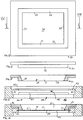
Fig. 4 is a front, exterior view of the front housing of the radome; -
Figs. 5 is a rear, interior view of the front housing of the radome before installation of a window assembly; -
Fig. 6 is the same view asFig. 5 after installation of a wiper unit of the window assembly; -
Figs. 7 and 8 are respectively a rear view and a side view of a window unit of the window assembly; -
Fig. 9 is a section through the window unit taken at IX - IX ofFig. 7 ; -
Fig. 10 is a top view of the window unit; -
Fig. 11 is a section through the window unit taken at XI - XI ofFig. 7 ; -
Figs. 12 and 13 are respectively a rear view and a top view of the wiper unit; -
Fig. 14 is a section through the wiper unit taken at XIV - XIV ofFig. 12 ; -
Fig. 15 is a section through a fixed frame of the window assembly taken at XV - XV ofFig. 17 ; -
Fig. 16 is a section through the window assembly taken at XVI - XVI ofFig. 20 , showing the window unit, wiper unit and fixed frame in the sectional views ofFigs. 11 ,14 and 15 in the assembled condition; -
Figs. 17 and 18 are respectively a rear view and a top view of the fixed frame; -
Fig. 19 is the same view asFig. 6 after installation of the fixed frame to retain the wiper unit, but without the window unit; -
Figs. 20 and 21 show the complete window assembly including the window unit in the same view asFig. 19 , respectively in the first position (Fig. 20 ) and the second position (Fig. 21 ); -
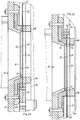
Figs. 22 is a section through the complete window assembly, taken in the first position at XXII - XXII ofFig. 20 ; -
Fig. 23 is a section through the complete window assembly, taken in the second position at XXIII - XXIII ofFig. 21 ; -
Figs. 24 and 25 are enlarged views of the housing aperture region ofFigs. 22 and 23 , respectively; and -
Fig. 26 illustrates a method of operation. - Reference numerals appearing in more than one of the figures indicate the same or corresponding parts in each of them.
- Referring to
Figs. 1-4 andFigs. 22 - 23 , a pair of radar antennas 1 are mounted, each in a use position within arespective radome 10 which defines abarrier assembly base 12 and having afront housing 13 with anaperture 14 protected by anexternal cowling 15. The field of view of the antenna 1 is defined by the electromagnetic waves orsignals 2 which are sent from and received by the antenna via theaperture 14. The barrier assembly further comprises a moveable barrier formed as apanel 25. Theaperture 14 is closed by awindow portion panel 25. Thepanel 25 is electromagnetically transmissive, which is to say, transparent to the electromagnetic waves orsignals 2, and forms part of awindow unit 20 as further described below. In the illustrated example, the body 11 andfront housing 13 forming the rest of thebarrier assembly - In the illustrated arrangement, each
radome 10 is arranged and adjusted, e.g. in rotation on its base to a fixed use position. In this position the field of view of each antenna (which is to say, the area outside the radome which can receive signals from the antenna and return signals to the antenna), represented inFig. 1 by the divergent dotted lines indicating thesignals 2 at the boundaries of the field of view, covers a portion of a level crossing where aroadway 3 intersects arailway 4.Barrier arms 5 are arranged to prevent traffic on the roadway from crossing the railway when a train approaches. - The
window portion radome 10 is arranged so that signals may pass through it to and from the respective antenna 1. In the illustrated example, the antenna receivessignals 2 returned from a fixed target, comprising in toto all the fixed elements of the environment such as therailway 4 as illustrated within its field of view. As illustrated, theopposite radome 10 may form part of the fixed target, or alternatively each radome may be arranged so that the opposite radome is not included in the field of view. - Each antenna 1 may operate at a frequency of about 30GHz or more, for example, in the range from about 30GHz to about 110 GHz. The
signals 2 sent from and received by each antenna 1 are processed by a radar control system 8 which may be connected to an internal and/or external electrical power supply (not shown). The control system senses changes in the signals using signal processing techniques as well known in the art to determine, inter alia, whether the fixed environment has changed, indicating the presence of an obstruction on the railway, and whether the signals have become attenuated indicating the presence of a water film or drops of water on theexternal surface 23 of thewindow portion actuator 9 to wipe theexternal surface 23 of thepanel 25 with at least one wiper. Theactuator 9 is illustrated as a linear actuator with a reciprocating drive rod, but could be a crank, a rack and pinion, or any other suitable mechanism. - Referring to
Figs. 7-11 , thewindow unit 20 comprises aframe 26 having aconnector portion 27 by which it is connected to theactuator 9. The window portion of the barrier comprises thethin panel 25 of electromagnetically transmissive material as known in the art, which is fixedly supported in theframe 26. Thepanel 25 may have a thickness between its opposite,external surface 23 andinternal surface 24 approximately equal to half of the wavelength of the operating frequency of the antenna. Thepanel 25 could be a solid sheet, a fabric or a laminated or composite material. It may be made from or coated with, for example, PTFE or other suitable plastics material. Theframe 26 holds thepanel 25 all around its edge to support it and keep it flat in use. Thepanel 25 may be clamped or bonded to theframe 26 all around its edge so that the frame exerts a tension force on the leading edge of the panel as it moves, helping to pull the panel between thewipers supports 47 as further explained below. - The
entire panel 25 exposed within theframe 26 may be electromagnetically transmissive, including its lower part which defines the first,lower window portion 21, its upper part which defines the second,upper window portion 22, and itsintermediate region 28 which extends contiguously between the first and second window portions and lies behind theupper wiper 32 in the first position of the window unit as further explained below, so that no parts of thepanel 25 between the first and second window portions are electromagnetically opaque. - Referring to
Figs. 12 -14 , in the illustrated example, the at least one wiper comprises a first,lower wiper 31 and the second,upper wiper 32 which form the respective lower and upper sides of awiper unit 30, formed as a frame whoseinward edges 33 define acentral aperture 34. The wipers may be formed from a rubber or plastics material, and could be moulded or extruded, for example, in neoprene or another suitable elastomer. - Referring also to
Figs. 5, 6 , and22 - 25 , theaperture 14 of thefront housing 13 is surrounded by an inwardly facinglip 16. The wiper unit is arranged around theaperture 14 so that thelip 16 extends into theaperture 34 as shown inFig. 6 , and retained in that position by a fixedframe 40. In use, the wiper unit forms a seal between thefront housing 13 and thepanel 25 all round theaperture 14 of the front housing. - Referring to
Figs. 15 ,17 and 18 , the fixedframe 40 defines grooves orslideways 41. On the forwardly facing side of the slideways is arectangular frame portion 42 defining arecess 43 surrounding anaperture 44 which is open through the front and rear sides of the fixed frame. Theaperture 44 intersects the windowunit receiving space 45 bounded by theslideways 41 which opens through the top and bottom ends of the fixed frame, so that therespective window portions window unit 20 are exposed in theaperture 44 as the window unit slides along the length axis of the fixed frame. - On the rearwardly facing side of the slideways are two fixed
bars 46, eachbar 46 having asupport 47 which extends into the windowunit receiving space 45 in contact with theinternal surface 24 of thepanel 25. The supports may be made from or coated with a material providing a low coefficient of friction, e.g. a felt material or a plastics material such as PTFE, or may be arranged as rollers or the like, so that they press against theinternal surface 24 of thewindow portions panel 25, optionally also providing a wiping or cleaning action, as thewindow unit 20 slides past thesupports 47 in use. -
Fig. 19 shows how the fixedframe 40 is fixed to thefront housing 13 to retain thewiper unit 30 in therecess 43 so that itsinward edges 33 extend into the windowunit receiving space 45 where they are exposed between therectangular frame portion 42 and thelip 16 of the front housing. For clarity, the window unit is not shown inFig. 19 ; in practice however, thewindow unit 20 is arranged in the windowunit receiving space 45 with its long edges in theslideways 41 before the fixedframe 40 is installed in thefront housing 13 as shown. - Referring to
Fig. 16 andFigs. 20 - 25 , once fully assembled, eachwiper external surface 23 of thepanel 25 which forms part of the barrier assembly protecting the antenna 1 from the weather. - In the assembled position it can be seen that the first and
second wipers lip 16 of thefront housing 13 and theinward edges 33 of thewiper unit 30, with thepanel 25 together with themoveable frame 26 of thewindow unit 20 being slidable up and down relative to the fixedframe panel 25 is received in compression between eachwiper respective support 47 which is arranged in opposed relation to the wiper, so that theexternal surface 23 of thepanel 25 is pressingly engaged against theinward edge 33 of thewiper window unit 20 moves between the first and second positions, thepanel 25 sliding between eachwiper respective support 47. - The
actuator 9 and radar control system 8 together form an actuator means for wiping theexternal surface 23 of the barrier with thewipers window portions window unit 20 including theframe 26 and thepanel 25 which forms part of the barrier assembly, in sliding translation relative to the antenna 1 and thewipers Figs. 20 ,22 and24 , in which signals may pass through thefirst window portion 21 of thepanel 25 to the antenna 1, and the second (downward) position as shown inFigs. 21 ,23 and25 , in which signals may pass through thesecond window portion 22 of thepanel 25 to the antenna 1. - The
wipers external surface 23 of thepanel 25 forming the moveable barrier as thepanel 25 moves relative to the antenna 1 and thewipers lower wiper 31 being arranged to wipe water from the first,lower window portion 21 when thepanel 25 is moved from the first position to the second position, the second,upper wiper 32 being arranged to wipe water from the second,upper window portion 22 when thepanel 25 is moved from the second position back to the first position. - Referring to
Fig. 2 , it can be seen that thefront housing 13 including thewindow unit 20,wiper unit 30 and fixedframe 40 may be inclined somewhat forwardly and downwardly in its use position. This helps to keep rain off the exposed external surface of thewindow portion panel 25 may be arranged as shown to move generally downwardly from the first position to the second position, and upwardly from the second position to the first position, wherein "upwardly" and "downwardly" are construed to mean a vector having at least a vertical component, preferably a major vertical component. - As illustrated, the radome may be arranged to enclose the external and
internal surfaces second window portion 22 in the first position of thewindow unit 20, and optionally also to enclose the external andinternal surfaces first window portion 21 in the second position of thewindow unit 20. Thus, thewindow unit 20 may be parked in a first, default or rest position with the first,lower window portion 21 exposed, while the second, upper window portion is enclosed and protected within thefront housing 13 as shown inFigs. 20 ,22 and24 . The default or rest position may be an upward position as shown, so that even if thelower wiper 31 becomes worn, the upper,second window portion 22 will remain dry in rainy weather. - In its upward or first position, rain will tend to run down the
first window portion 21 to theinward edge 33 of thelower wiper 31. As thepanel 25 moves to the second (downward) position), water remaining on thefirst window portion 21 will be wiped off by thelower wiper 31, so that the first window portion is dried as it moves inside thefront housing 13. - As the panel moves back to the first (upward) position, any rain that has accumulated on the second,
upper window portion 22 is wiped off by theupper wiper 32, so that thesecond window portion 22 is dried as it moves back inside thefront housing 13. - The control system may be arranged to operate the antenna in a detection cycle during which one or
more signals 2 are received by the antenna 1 via the respective first orsecond window portion panel 25 to sense changes in its field of view. The detection cycle may be repeated regularly or triggered by an external event. - The actuator means 8, 9 may be arranged to move the
window unit 20 from the first position to the second position prior to commencement of a detection cycle, which takes place in the second position of thewindow unit 20, and to return the barrier from the second position to the first position responsive to completion of the detection cycle. - The actuator means 8, 9 may be arranged to move the
window unit 20 from the first position to the second position responsive to a sensed attenuation ofsignals 2 received by the antenna 1 via thefirst window portion 21 of the barrier. If thesignals 2 received via thefirst window portion 21 are not attenuated by water drops or a water film on theexternal surface 23 of thefirst window portion 21, then thewindow unit 20 may remain in the first (upward) position while the detection cycle takes place. - For example, the control system 8 may be arranged to determine an attenuation or a degree of attenuation of
signals 2 received by the antenna 1 via thefirst window portion 21 of the barrier in the first position, prior to commencing a detection cycle. - The control system 8 may determine whether a second, later signal is attenuated relative to a first, earlier signal, and optionally whether the degree of attenuation of the second signal relative to the first signal is greater than a predefined threshold value, which may be set during installation or reset regularly, for example, every time the
window unit 20 moves back to its parked, first position. If the second, later signal is determined to be attenuated relative to the first, earlier signal, or if the degree of attenuation is determined to be greater than the threshold value, then the control system 8 may operate theactuator 9 to move thewindow unit 20 from the first position to the second position prior to commencement of the detection cycle, and then to return thewindow unit 20 from the second position to the first, parked position responsive to completion of the detection cycle. - If the second, later signal is determined not to be attenuated relative to the first, earlier signal, or if the degree of attenuation is determined to be less than the threshold value, then the control system 8 may be arranged not to move the window unit prior to commencement of the detection cycle, so that the
signal 2 is received via thefirst window portion 21 during the detection cycle. -
Fig. 26 shows how the barrier may be moved to the first position (step 101) before receiving at least afirst signal 2 returned from the fixed target via the first window portion 21 (step 102). At some later time, asecond signal 2 is returned from the same fixed target and received via the first window portion 21 (step 103). - The control system 8 determines at step 104 a degree of attenuation of the second signal relative to the first signal, and at
step 105 determines whether the degree of attenuation is greater than a threshold value. - At
step 106, responsive to determining that the degree of attenuation is greater than the threshold value, the control system 8 commands theactuator 9 to move thewindow unit 20 from the first position to the second position; and then atstep 107 commences a detection cycle of the antenna during which a further signal or signals 2 are returned from the target and received via thesecond window portion 22, which remains dry because it was protected inside thefront housing 13 until moved into position just before commencing the detection cycle. The detection cycle is completed at step 108 before returning thewindow unit 20 at step 109 from the second position to the first position. - If the degree of attenuation is not greater than the threshold value, then the
window unit 20 remains in the first position while the detection cycle is commenced (step 110) and completed (step 111). - The threshold value may be updated by signals received, either during or after a detection cycle, optionally after returning the
window unit 20 to the first position. The sequence is then repeated to determine whether each subsequent detection cycle occurs in the first or second position of thewindow unit 20. - The novel radome may be used to provide more reliable and effective operation during rainy weather, particularly for a radar antenna operating at a frequency of about 30GHz or above. The mechanical wiping action is more effective than prior art arrangements which rely on warm air to dry the external surface of a radome. The barrier may be arranged to move rapidly between the first and second positions, providing a fast and effective wiping action which does not interrupt the iterative detection cycle of the radar.
- By arranging a support in contact with the internal surface of the barrier and in opposed relation to the wiper, it is possible to ensure that the entire external surface of the barrier is pressingly engaged against the wiper as the barrier moves between the first and second positions. Thus, even when the barrier material is very thin, and even in the event that it should become deformed over time, an effective wiping action is obtained.
- Since the or each wiper remains outside the field of view of the radar throughout the wiping operation, and conveniently may be fixed in a static position relative to the antenna, there is no risk that a wiper may fail in a position where it partially obstructs the field of view of the radar, even in the event that the thin material of the barrier should deform over time.
- Moreover, by arranging the intermediate region of the barrier which extends between the first and second window portions to be electromagnetically transmissive, so that there are no non-transmissive regions of the barrier between the first and second window portions, it is possible to ensure that signals may pass through the barrier to the antenna when the barrier is in any intermediate position between the first and second positions. Thus, in the event of failure of the actuator means, the radar may continue to operate even though the wiping mechanism is disabled.
- In applications where the radar is arranged to view a fixed target, the service life of the barrier and wiping mechanism may be extended by arranging for the mechanism to operate responsive to a sensed attenuation of the signal received from the fixed target. Thus, when there is little or no attenuation of the signal returned from the fixed target is sensed, the wiping action may be suspended so that the barrier remains in the first position. In practice, wiping may be required only occasionally, so there is little wear of the thin material of the barrier, increasing the service life of the assembly.
- The improved reliability of the wiping mechanism, longer service life and and reduced likelihood of obstruction of the radar antenna provides a better solution for safety critical applications, particularly in a fixed position, for example, in monitoring obstructions on a level crossing at the intersection of a roadway and a railway.
- In summary, a radar antenna is protected by a radome including a barrier, which may be formed as a panel and is moveable between first and second positions in which the antenna may receive signals via respective first and second window portions of the barrier. One or more wipers are arranged to wipe water from an external surface of the barrier as it moves between the first and second positions. The barrier may be moveable responsive to a determination of the degree of attenuation of the sgnals by water on the external surface of the respective window portion.
- The antenna 1 may be of any conventional design and is not shown in detail. The radar control system 8 may include a processor, memory, and other conventional elements as known in the art.
- In alternative embodiments more than two window portions might be provided, with the barrier being movable continuously or stepwise between multiple different positions. The constructional details of the assembly components could be other than as shown. For example, an assembly of separate components could be used instead of the fixed frame to retain the wipers and the window unit. Only one wiper or more than two wipers might be provided. The wiper or wipers need not form part of a frame; the or each wiper could be for example an extruded strip. The barrier might be movable in rotation rather than, as illustrated, in translation. It could move horizontally rather than vertically.
- Conveniently, as in the illustrated embodiment, the or each wiper may be arranged in a fixed position relative to the antenna, optionally also relative to the fixed parts of the barrier assembly forming the fixed structure of the radome, so that it remains in its fixed position relative to the antenna as the barrier moves relative to the wiper(s) and antenna between the first and second positions.
- Alternatively however, the or each wiper could be movable relative to the antenna, optionally also relative to the fixed parts of the barrier assembly forming the fixed structure of the radome, as the barrier moves relative to the antenna and the or each wiper.
- The barrier could be arranged to move, for example on a timed schedule or responsive to any desired sensor input, other than in response to a sensed attenuation of the signal received by the radar antenna.
- Although conveniently, as in the illustrated example, the barrier formed by the
panel 25 is moveable in a static position of the antenna 1 andwipers - Many further possible adaptations within the scope of the claims will be evident to those skilled in the art.
- In the claims, reference numerals and characters in parentheses are provided for ease of reference and should not be construed as limiting features.
Claims (15)
- A radome (10) for a radar antenna (1), the radome including in a use position of the antenna:a barrier (25), the barrier being arranged so that signals (2) may pass through an electromagnetically transmissive window portion (21, 22) of the barrier to the antenna,at least one wiper (31, 32) arranged in contact with an external surface (23) of the barrier, andan actuator means (8, 9) for wiping the external surface of the barrier with the at least one wiper to remove water from the window portion; whereinthe barrier defines at least a first said electromagnetically transmissive window portion (21) and a second said electromagnetically transmissive window portion (22); and characterised in thatthe actuator means (8, 9) is arranged to move the barrier (25) relative to the antenna (1) and the at least one wiper (31, 32) between a first position in which signals may pass through the first window portion (21) of the barrier to the antenna, and a second position in which signals may pass through the second window portion (22) of the barrier to the antenna;the at least one wiper being arranged to wipe the external surface of the barrier as the barrier moves relative to the antenna and the at least one wiper between the first and second positions.
- A radome according to claim 1, wherein the radome is arranged to enclose the second window portion (22) of the barrier in the first position of the barrier.
- A radome according to claim 2, wherein the radome is arranged to enclose the first window portion (21) of the barrier in the second position of the barrier.
- A radome according to claim 1, wherein at least one support (47) is arranged in contact with an internal surface (24) of the barrier (25) opposite the external surface (23), and the barrier is slidable between the at least one wiper (31, 32) and the at least one support (47).
- A radome according to claim 1, wherein a first said wiper (31) and a second said wiper (32) are provided, the first wiper (31) being arranged to wipe water from the first window portion (21) when the barrier is moved from the first position to the second position, the second wiper (32) being arranged to wipe water from the second window portion (22) when the barrier is moved from the second position to the first position.
- A radome according to claim 5, wherein the first and second wipers (31, 32) define opposite, upper and lower sides of a fixed frame, and the barrier (25) comprises a panel which is slidable up and down relative to the fixed frame.
- A radome according to claim 1, wherein the actuator means (8, 9) includes a radar control system (8), and is arranged to move the barrier relative to the antenna and the at least one wiper from the first position to the second position responsive to sensing, by the radar control system (8), an attenuation of signals received by the antenna via the first window portion (21) of the barrier.
- A radome according to claim 1, wherein the actuator means (8, 9) includes a radar control system (8), the radar control system (8) being arranged to operate the antenna (1) in a detection cycle; and the actuator means (8, 9) is arranged to move the barrier relative to the antenna and the at least one wiper from the first position to the second position prior to commencement of the detection cycle of the antenna, and to return the barrier from the second position to the first position responsive to completion of the detection cycle;
the detection cycle including at least receiving a signal by the antenna via the second window portion (22) of the barrier. - A radome according to claim 1, wherein the actuator means (8, 9) includes a radar control system (8), the radar control system (8) being arranged to operate the antenna (1) in a detection cycle, and to determine an attenuation of signals received by the antenna via the first window portion (21) of the barrier in the first position of the barrier prior to commencing the detection cycle of the antenna; and the actuator means (8, 9) is arranged:responsive to determining that a respective, later one of the signals is attenuated relative to an earlier one of the signals,to move the barrier relative to the antenna and the at least one wiper from the first position to the second position prior to commencement of the detection cycle, and thento return the barrier from the second position to the first position responsive to completion of the detection cycle; and,responsive to determining that the respective, later one of the signals is not attenuated relative to the earlier one of the signals, not to move the barrier relative to the antenna and the at least one wiper from the first position to the second position prior to commencement of the detection cycle;the detection cycle including at least receiving a signal by the antenna via the barrier (25).
- A radome according to claim 1, wherein the barrier is arranged to move downwardly from the first position to-the second position, and upwardly from the second position to the first position.
- A radome according to claim 1, wherein the barrier (25) comprises a panel supported in a moveable frame (26), and the actuator means is arranged to move the frame and the panel together relative to the antenna and the at least one wiper between the first and second positions.
- A radome according to claim 1, wherein an intermediate region (28) of the barrier between the first (21) and second (22) window portions is electromagnetically transmissive, and the barrier is arranged so that signals may pass through the barrier to the antenna when the barrier is in any intermediate position between the first and second positions.
- A method of wiping water from a radome (10) for a radar antenna (1), including:arranging a barrier (25) of the radome so that signals (2) may pass through an electromagnetically transmissive window portion (21, 22) of the barrier to the antenna;arranging at least one wiper (31, 32) in contact with an external surface (23) of the barrier; andwiping the external surface of the barrier with the at least one wiper to remove water from the window portion; and further including:providing the barrier with at least a first said electromagnetically transmissive window portion (21) and a second said electromagnetically transmissive window portion (22); characterised bymoving the barrier relative to the antenna and the at least one wiper between a first position in which signals may pass through the first window portion (21) of the barrier to the antenna, and a second position in which signals may pass through the second window portion (22) of the barrier to the antenna; andwiping the external surface (23) of the barrier with the at least one wiper as the barrier moves relative to the antenna and the at least one wiper between the first and second positions.
- A method according to claim 13, including:arranging the antenna (1) to send signals (2), via the first and second window portions (21, 22) of the barrier (25), to a fixed target (4);moving the barrier to the first position;receiving, by the antenna, via the first window portion (21) of the barrier, a first signal returned from the target; and thenreceiving, by the antenna, via the first window portion (21) of the barrier, a second signal returned from the target;determining whether the second signal is attenuated relative to the first signal; and then,responsive to determining that the second signal is attenuated relative to the first signal:moving the barrier (25), relative to the antenna (1) and the at least one wiper (31, 32), from the first position to the second position; and thencommencing a detection cycle of the antenna, the detection cycle including at least receiving, by the antenna, via the second window portion (22) of the barrier, a third signal returned from the target; and then,after completing the detection cycle, returning the barrier from the second position to the first position.
- A method according to claim 14, including:
moving the barrier (25) downwardly from the first position to the second position, and upwardly from the second position to the first position.
Priority Applications (1)
| Application Number | Priority Date | Filing Date | Title |
|---|---|---|---|
| EP17425132.2A EP3486996B1 (en) | 2017-11-20 | 2017-11-20 | Radome with wiping mechanism |
Applications Claiming Priority (1)
| Application Number | Priority Date | Filing Date | Title |
|---|---|---|---|
| EP17425132.2A EP3486996B1 (en) | 2017-11-20 | 2017-11-20 | Radome with wiping mechanism |
Publications (2)
| Publication Number | Publication Date |
|---|---|
| EP3486996A1 EP3486996A1 (en) | 2019-05-22 |
| EP3486996B1 true EP3486996B1 (en) | 2021-09-01 |
Family
ID=61655558
Family Applications (1)
| Application Number | Title | Priority Date | Filing Date |
|---|---|---|---|
| EP17425132.2A Active EP3486996B1 (en) | 2017-11-20 | 2017-11-20 | Radome with wiping mechanism |
Country Status (1)
| Country | Link |
|---|---|
| EP (1) | EP3486996B1 (en) |
Families Citing this family (2)
| Publication number | Priority date | Publication date | Assignee | Title |
|---|---|---|---|---|
| US12362470B1 (en) * | 2021-11-18 | 2025-07-15 | Waymo Llc | Systems, methods, and apparatus for determining characteristics of a radome |
| CN118712735A (en) * | 2024-08-21 | 2024-09-27 | 人天通信集团有限公司 | Air conditioning type antenna beautification cover |
Family Cites Families (2)
| Publication number | Priority date | Publication date | Assignee | Title |
|---|---|---|---|---|
| JP2005291808A (en) * | 2004-03-31 | 2005-10-20 | Fujitsu Ltd | In-vehicle radar system |
| JP2012237724A (en) * | 2011-05-13 | 2012-12-06 | Nippon Signal Co Ltd:The | Rail road crossing obstacle detector |
-
2017
- 2017-11-20 EP EP17425132.2A patent/EP3486996B1/en active Active
Also Published As
| Publication number | Publication date |
|---|---|
| EP3486996A1 (en) | 2019-05-22 |
Similar Documents
| Publication | Publication Date | Title |
|---|---|---|
| EP3486996A1 (en) | Radome with wiping mechanism | |
| EP2708915B1 (en) | Partial covering radome for a radar unit | |
| KR102301660B1 (en) | Sensor cleaning system with rotating window | |
| JP6685350B2 (en) | Aircraft Transparency with Pressure Seal and / or Antistatic Drain | |
| EP1268236A1 (en) | Tactile sensor | |
| KR102095615B1 (en) | Rain intensity sensor | |
| WO2017023221A1 (en) | A vehicle wiper unit | |
| KR20200044187A (en) | Cover Circulation type Sensor Protection Device and Autonomous Vehicle Thereof | |
| US20160161831A1 (en) | Hidden camera assembly with microprocessor control | |
| AU2003218540A1 (en) | Door assembly | |
| CN114951055A (en) | Sensor assembly with non-contact surface cleaning system for cameras, sensors, lidar and the like | |
| EP3414146B1 (en) | Drain valve | |
| US3893203A (en) | Drive motor for cleaning glass surfaces | |
| EP1071860B1 (en) | Force-responsive detectors and systems and methods of making them | |
| US2866881A (en) | Temperature controlled electrically heated window and window wiper system | |
| EP1099231A1 (en) | Force-responsive detectors and systems | |
| CN113917405A (en) | Mounting device of vehicle-mounted radar | |
| KR102326207B1 (en) | Vehicle and control method for the same | |
| EP0619199B1 (en) | Sealing and wiping arrangement | |
| US11420595B2 (en) | Cleaning unit for cleaning foreign matter from a cover, in particular a cover of a transmitter/receiver window of a driving environment sensor, and device for sensing the environment and method | |
| US5044042A (en) | Windshield wiper blade with dual wiping edges | |
| CN216217102U (en) | Image sensor's protector and vehicle | |
| US20240019557A1 (en) | See-through assembly for an environment sensor of a motor vehicle | |
| CN115977514B (en) | A self-cleaning aluminum alloy door and window with rain sensing function | |
| JPH06179348A (en) | Vehicle wiper device |
Legal Events
| Date | Code | Title | Description |
|---|---|---|---|
| STAA | Information on the status of an ep patent application or granted ep patent |
Free format text: STATUS: UNKNOWN |
|
| PUAI | Public reference made under article 153(3) epc to a published international application that has entered the european phase |
Free format text: ORIGINAL CODE: 0009012 |
|
| STAA | Information on the status of an ep patent application or granted ep patent |
Free format text: STATUS: THE APPLICATION HAS BEEN PUBLISHED |
|
| AK | Designated contracting states |
Kind code of ref document: A1 Designated state(s): AL AT BE BG CH CY CZ DE DK EE ES FI FR GB GR HR HU IE IS IT LI LT LU LV MC MK MT NL NO PL PT RO RS SE SI SK SM TR |
|
| AX | Request for extension of the european patent |
Extension state: BA ME |
|
| STAA | Information on the status of an ep patent application or granted ep patent |
Free format text: STATUS: REQUEST FOR EXAMINATION WAS MADE |
|
| 17P | Request for examination filed |
Effective date: 20191125 |
|
| RBV | Designated contracting states (corrected) |
Designated state(s): AL AT BE BG CH CY CZ DE DK EE ES FI FR GB GR HR HU IE IS IT LI LT LU LV MC MK MT NL NO PL PT RO RS SE SI SK SM TR |
|
| RIC1 | Information provided on ipc code assigned before grant |
Ipc: G01S 13/91 20060101ALI20210215BHEP Ipc: G01S 13/931 20200101ALN20210215BHEP Ipc: B61L 23/04 20060101ALI20210215BHEP Ipc: B61L 29/30 20060101ALI20210215BHEP Ipc: H01Q 1/32 20060101ALI20210215BHEP Ipc: H01Q 1/02 20060101AFI20210215BHEP Ipc: G01S 7/40 20060101ALN20210215BHEP Ipc: H01Q 1/42 20060101ALI20210215BHEP |
|
| GRAP | Despatch of communication of intention to grant a patent |
Free format text: ORIGINAL CODE: EPIDOSNIGR1 |
|
| STAA | Information on the status of an ep patent application or granted ep patent |
Free format text: STATUS: GRANT OF PATENT IS INTENDED |
|
| RIC1 | Information provided on ipc code assigned before grant |
Ipc: H01Q 1/42 20060101ALI20210222BHEP Ipc: H01Q 1/02 20060101AFI20210222BHEP Ipc: G01S 7/40 20060101ALN20210222BHEP Ipc: B61L 29/30 20060101ALI20210222BHEP Ipc: H01Q 1/32 20060101ALI20210222BHEP Ipc: B61L 23/04 20060101ALI20210222BHEP Ipc: G01S 13/91 20060101ALI20210222BHEP Ipc: G01S 13/931 20200101ALN20210222BHEP |
|
| RIC1 | Information provided on ipc code assigned before grant |
Ipc: G01S 7/40 20060101ALN20210318BHEP Ipc: G01S 13/931 20200101ALN20210318BHEP Ipc: B61L 29/30 20060101ALI20210318BHEP Ipc: B61L 23/04 20060101ALI20210318BHEP Ipc: G01S 13/91 20060101ALI20210318BHEP Ipc: H01Q 1/32 20060101ALI20210318BHEP Ipc: H01Q 1/42 20060101ALI20210318BHEP Ipc: H01Q 1/02 20060101AFI20210318BHEP |
|
| INTG | Intention to grant announced |
Effective date: 20210331 |
|
| GRAS | Grant fee paid |
Free format text: ORIGINAL CODE: EPIDOSNIGR3 |
|
| GRAA | (expected) grant |
Free format text: ORIGINAL CODE: 0009210 |
|
| STAA | Information on the status of an ep patent application or granted ep patent |
Free format text: STATUS: THE PATENT HAS BEEN GRANTED |
|
| AK | Designated contracting states |
Kind code of ref document: B1 Designated state(s): AL AT BE BG CH CY CZ DE DK EE ES FI FR GB GR HR HU IE IS IT LI LT LU LV MC MK MT NL NO PL PT RO RS SE SI SK SM TR |
|
| REG | Reference to a national code |
Ref country code: GB Ref legal event code: FG4D |
|
| REG | Reference to a national code |
Ref country code: CH Ref legal event code: EP Ref country code: AT Ref legal event code: REF Ref document number: 1427178 Country of ref document: AT Kind code of ref document: T Effective date: 20210915 |
|
| REG | Reference to a national code |
Ref country code: DE Ref legal event code: R096 Ref document number: 602017045102 Country of ref document: DE |
|
| REG | Reference to a national code |
Ref country code: IE Ref legal event code: FG4D |
|
| REG | Reference to a national code |
Ref country code: LT Ref legal event code: MG9D |
|
| REG | Reference to a national code |
Ref country code: NL Ref legal event code: MP Effective date: 20210901 |
|
| PG25 | Lapsed in a contracting state [announced via postgrant information from national office to epo] |
Ref country code: HR Free format text: LAPSE BECAUSE OF FAILURE TO SUBMIT A TRANSLATION OF THE DESCRIPTION OR TO PAY THE FEE WITHIN THE PRESCRIBED TIME-LIMIT Effective date: 20210901 Ref country code: SE Free format text: LAPSE BECAUSE OF FAILURE TO SUBMIT A TRANSLATION OF THE DESCRIPTION OR TO PAY THE FEE WITHIN THE PRESCRIBED TIME-LIMIT Effective date: 20210901 Ref country code: RS Free format text: LAPSE BECAUSE OF FAILURE TO SUBMIT A TRANSLATION OF THE DESCRIPTION OR TO PAY THE FEE WITHIN THE PRESCRIBED TIME-LIMIT Effective date: 20210901 Ref country code: BG Free format text: LAPSE BECAUSE OF FAILURE TO SUBMIT A TRANSLATION OF THE DESCRIPTION OR TO PAY THE FEE WITHIN THE PRESCRIBED TIME-LIMIT Effective date: 20211201 Ref country code: LT Free format text: LAPSE BECAUSE OF FAILURE TO SUBMIT A TRANSLATION OF THE DESCRIPTION OR TO PAY THE FEE WITHIN THE PRESCRIBED TIME-LIMIT Effective date: 20210901 Ref country code: NO Free format text: LAPSE BECAUSE OF FAILURE TO SUBMIT A TRANSLATION OF THE DESCRIPTION OR TO PAY THE FEE WITHIN THE PRESCRIBED TIME-LIMIT Effective date: 20211201 Ref country code: ES Free format text: LAPSE BECAUSE OF FAILURE TO SUBMIT A TRANSLATION OF THE DESCRIPTION OR TO PAY THE FEE WITHIN THE PRESCRIBED TIME-LIMIT Effective date: 20210901 Ref country code: FI Free format text: LAPSE BECAUSE OF FAILURE TO SUBMIT A TRANSLATION OF THE DESCRIPTION OR TO PAY THE FEE WITHIN THE PRESCRIBED TIME-LIMIT Effective date: 20210901 |
|
| REG | Reference to a national code |
Ref country code: AT Ref legal event code: MK05 Ref document number: 1427178 Country of ref document: AT Kind code of ref document: T Effective date: 20210901 |
|
| PG25 | Lapsed in a contracting state [announced via postgrant information from national office to epo] |
Ref country code: PL Free format text: LAPSE BECAUSE OF FAILURE TO SUBMIT A TRANSLATION OF THE DESCRIPTION OR TO PAY THE FEE WITHIN THE PRESCRIBED TIME-LIMIT Effective date: 20210901 Ref country code: LV Free format text: LAPSE BECAUSE OF FAILURE TO SUBMIT A TRANSLATION OF THE DESCRIPTION OR TO PAY THE FEE WITHIN THE PRESCRIBED TIME-LIMIT Effective date: 20210901 Ref country code: GR Free format text: LAPSE BECAUSE OF FAILURE TO SUBMIT A TRANSLATION OF THE DESCRIPTION OR TO PAY THE FEE WITHIN THE PRESCRIBED TIME-LIMIT Effective date: 20211202 |
|
| RAP2 | Party data changed (patent owner data changed or rights of a patent transferred) |
Owner name: ECM S.P.A. |
|
| PG25 | Lapsed in a contracting state [announced via postgrant information from national office to epo] |
Ref country code: AT Free format text: LAPSE BECAUSE OF FAILURE TO SUBMIT A TRANSLATION OF THE DESCRIPTION OR TO PAY THE FEE WITHIN THE PRESCRIBED TIME-LIMIT Effective date: 20210901 |
|
| PG25 | Lapsed in a contracting state [announced via postgrant information from national office to epo] |
Ref country code: IS Free format text: LAPSE BECAUSE OF FAILURE TO SUBMIT A TRANSLATION OF THE DESCRIPTION OR TO PAY THE FEE WITHIN THE PRESCRIBED TIME-LIMIT Effective date: 20220101 Ref country code: SM Free format text: LAPSE BECAUSE OF FAILURE TO SUBMIT A TRANSLATION OF THE DESCRIPTION OR TO PAY THE FEE WITHIN THE PRESCRIBED TIME-LIMIT Effective date: 20210901 Ref country code: SK Free format text: LAPSE BECAUSE OF FAILURE TO SUBMIT A TRANSLATION OF THE DESCRIPTION OR TO PAY THE FEE WITHIN THE PRESCRIBED TIME-LIMIT Effective date: 20210901 Ref country code: RO Free format text: LAPSE BECAUSE OF FAILURE TO SUBMIT A TRANSLATION OF THE DESCRIPTION OR TO PAY THE FEE WITHIN THE PRESCRIBED TIME-LIMIT Effective date: 20210901 Ref country code: PT Free format text: LAPSE BECAUSE OF FAILURE TO SUBMIT A TRANSLATION OF THE DESCRIPTION OR TO PAY THE FEE WITHIN THE PRESCRIBED TIME-LIMIT Effective date: 20220103 Ref country code: NL Free format text: LAPSE BECAUSE OF FAILURE TO SUBMIT A TRANSLATION OF THE DESCRIPTION OR TO PAY THE FEE WITHIN THE PRESCRIBED TIME-LIMIT Effective date: 20210901 Ref country code: EE Free format text: LAPSE BECAUSE OF FAILURE TO SUBMIT A TRANSLATION OF THE DESCRIPTION OR TO PAY THE FEE WITHIN THE PRESCRIBED TIME-LIMIT Effective date: 20210901 Ref country code: CZ Free format text: LAPSE BECAUSE OF FAILURE TO SUBMIT A TRANSLATION OF THE DESCRIPTION OR TO PAY THE FEE WITHIN THE PRESCRIBED TIME-LIMIT Effective date: 20210901 Ref country code: AL Free format text: LAPSE BECAUSE OF FAILURE TO SUBMIT A TRANSLATION OF THE DESCRIPTION OR TO PAY THE FEE WITHIN THE PRESCRIBED TIME-LIMIT Effective date: 20210901 |
|
| REG | Reference to a national code |
Ref country code: DE Ref legal event code: R097 Ref document number: 602017045102 Country of ref document: DE |
|
| PG25 | Lapsed in a contracting state [announced via postgrant information from national office to epo] |
Ref country code: MC Free format text: LAPSE BECAUSE OF FAILURE TO SUBMIT A TRANSLATION OF THE DESCRIPTION OR TO PAY THE FEE WITHIN THE PRESCRIBED TIME-LIMIT Effective date: 20210901 |
|
| PLBE | No opposition filed within time limit |
Free format text: ORIGINAL CODE: 0009261 |
|
| STAA | Information on the status of an ep patent application or granted ep patent |
Free format text: STATUS: NO OPPOSITION FILED WITHIN TIME LIMIT |
|
| REG | Reference to a national code |
Ref country code: CH Ref legal event code: PL |
|
| PG25 | Lapsed in a contracting state [announced via postgrant information from national office to epo] |
Ref country code: LU Free format text: LAPSE BECAUSE OF NON-PAYMENT OF DUE FEES Effective date: 20211120 Ref country code: DK Free format text: LAPSE BECAUSE OF FAILURE TO SUBMIT A TRANSLATION OF THE DESCRIPTION OR TO PAY THE FEE WITHIN THE PRESCRIBED TIME-LIMIT Effective date: 20210901 Ref country code: BE Free format text: LAPSE BECAUSE OF NON-PAYMENT OF DUE FEES Effective date: 20211130 |
|
| REG | Reference to a national code |
Ref country code: BE Ref legal event code: MM Effective date: 20211130 |
|
| 26N | No opposition filed |
Effective date: 20220602 |
|
| GBPC | Gb: european patent ceased through non-payment of renewal fee |
Effective date: 20211201 |
|
| PG25 | Lapsed in a contracting state [announced via postgrant information from national office to epo] |
Ref country code: SI Free format text: LAPSE BECAUSE OF FAILURE TO SUBMIT A TRANSLATION OF THE DESCRIPTION OR TO PAY THE FEE WITHIN THE PRESCRIBED TIME-LIMIT Effective date: 20210901 |
|
| REG | Reference to a national code |
Ref country code: DE Ref legal event code: R081 Ref document number: 602017045102 Country of ref document: DE Owner name: ECM S.P.A., IT Free format text: FORMER OWNER: PROGRESS RAIL INSPECTION & INFORMATION SYSTEMS S.R.L., BOLOGNA, IT Ref country code: DE Ref legal event code: R081 Ref document number: 602017045102 Country of ref document: DE Owner name: PROGRESS RAIL SIGNALING S.P.A., SERRAVALLE PIS, IT Free format text: FORMER OWNER: PROGRESS RAIL INSPECTION & INFORMATION SYSTEMS S.R.L., BOLOGNA, IT |
|
| PG25 | Lapsed in a contracting state [announced via postgrant information from national office to epo] |
Ref country code: IE Free format text: LAPSE BECAUSE OF NON-PAYMENT OF DUE FEES Effective date: 20211120 Ref country code: GB Free format text: LAPSE BECAUSE OF NON-PAYMENT OF DUE FEES Effective date: 20211201 |
|
| PG25 | Lapsed in a contracting state [announced via postgrant information from national office to epo] |
Ref country code: FR Free format text: LAPSE BECAUSE OF NON-PAYMENT OF DUE FEES Effective date: 20211130 |
|
| P01 | Opt-out of the competence of the unified patent court (upc) registered |
Effective date: 20230517 |
|
| PG25 | Lapsed in a contracting state [announced via postgrant information from national office to epo] |
Ref country code: CY Free format text: LAPSE BECAUSE OF FAILURE TO SUBMIT A TRANSLATION OF THE DESCRIPTION OR TO PAY THE FEE WITHIN THE PRESCRIBED TIME-LIMIT Effective date: 20210901 |
|
| PG25 | Lapsed in a contracting state [announced via postgrant information from national office to epo] |
Ref country code: LI Free format text: LAPSE BECAUSE OF NON-PAYMENT OF DUE FEES Effective date: 20220701 Ref country code: HU Free format text: LAPSE BECAUSE OF FAILURE TO SUBMIT A TRANSLATION OF THE DESCRIPTION OR TO PAY THE FEE WITHIN THE PRESCRIBED TIME-LIMIT; INVALID AB INITIO Effective date: 20171120 Ref country code: CH Free format text: LAPSE BECAUSE OF NON-PAYMENT OF DUE FEES Effective date: 20220701 |
|
| REG | Reference to a national code |
Ref country code: DE Ref legal event code: R081 Ref document number: 602017045102 Country of ref document: DE Owner name: PROGRESS RAIL SIGNALING S.P.A., SERRAVALLE PIS, IT Free format text: FORMER OWNER: ECM S.P.A., SERRAVALLE PISTOIESE (PISTOIA), IT |
|
| PG25 | Lapsed in a contracting state [announced via postgrant information from national office to epo] |
Ref country code: MK Free format text: LAPSE BECAUSE OF FAILURE TO SUBMIT A TRANSLATION OF THE DESCRIPTION OR TO PAY THE FEE WITHIN THE PRESCRIBED TIME-LIMIT Effective date: 20210901 |
|
| PG25 | Lapsed in a contracting state [announced via postgrant information from national office to epo] |
Ref country code: MT Free format text: LAPSE BECAUSE OF FAILURE TO SUBMIT A TRANSLATION OF THE DESCRIPTION OR TO PAY THE FEE WITHIN THE PRESCRIBED TIME-LIMIT Effective date: 20210901 |
|
| PG25 | Lapsed in a contracting state [announced via postgrant information from national office to epo] |
Ref country code: TR Free format text: LAPSE BECAUSE OF FAILURE TO SUBMIT A TRANSLATION OF THE DESCRIPTION OR TO PAY THE FEE WITHIN THE PRESCRIBED TIME-LIMIT Effective date: 20210901 |
|
| PGFP | Annual fee paid to national office [announced via postgrant information from national office to epo] |
Ref country code: DE Payment date: 20251022 Year of fee payment: 9 |
|
| PGFP | Annual fee paid to national office [announced via postgrant information from national office to epo] |
Ref country code: IT Payment date: 20251022 Year of fee payment: 9 |