EP3486990A1 - Rechargeable battery - Google Patents
Rechargeable battery Download PDFInfo
- Publication number
- EP3486990A1 EP3486990A1 EP17827802.4A EP17827802A EP3486990A1 EP 3486990 A1 EP3486990 A1 EP 3486990A1 EP 17827802 A EP17827802 A EP 17827802A EP 3486990 A1 EP3486990 A1 EP 3486990A1
- Authority
- EP
- European Patent Office
- Prior art keywords
- current collecting
- rechargeable battery
- electrode
- collecting member
- cap plate
- Prior art date
- Legal status (The legal status is an assumption and is not a legal conclusion. Google has not performed a legal analysis and makes no representation as to the accuracy of the status listed.)
- Granted
Links
- 238000007789 sealing Methods 0.000 claims abstract description 27
- 239000012774 insulation material Substances 0.000 claims abstract description 4
- 230000008878 coupling Effects 0.000 claims description 18
- 238000010168 coupling process Methods 0.000 claims description 18
- 238000005859 coupling reaction Methods 0.000 claims description 18
- 239000000463 material Substances 0.000 claims description 3
- 238000004519 manufacturing process Methods 0.000 description 7
- 238000000034 method Methods 0.000 description 6
- 238000009413 insulation Methods 0.000 description 3
- WHXSMMKQMYFTQS-UHFFFAOYSA-N Lithium Chemical compound [Li] WHXSMMKQMYFTQS-UHFFFAOYSA-N 0.000 description 1
- HBBGRARXTFLTSG-UHFFFAOYSA-N Lithium ion Chemical compound [Li+] HBBGRARXTFLTSG-UHFFFAOYSA-N 0.000 description 1
- 229910052782 aluminium Inorganic materials 0.000 description 1
- XAGFODPZIPBFFR-UHFFFAOYSA-N aluminium Chemical compound [Al] XAGFODPZIPBFFR-UHFFFAOYSA-N 0.000 description 1
- 230000001413 cellular effect Effects 0.000 description 1
- 239000004020 conductor Substances 0.000 description 1
- 230000000694 effects Effects 0.000 description 1
- 230000007717 exclusion Effects 0.000 description 1
- 229910052744 lithium Inorganic materials 0.000 description 1
- 229910001416 lithium ion Inorganic materials 0.000 description 1
- 229910052751 metal Inorganic materials 0.000 description 1
- 239000002184 metal Substances 0.000 description 1
- 238000012986 modification Methods 0.000 description 1
- 230000004048 modification Effects 0.000 description 1
- 230000000149 penetrating effect Effects 0.000 description 1
- 229920000642 polymer Polymers 0.000 description 1
- 229910001220 stainless steel Inorganic materials 0.000 description 1
- 239000010935 stainless steel Substances 0.000 description 1
Images


Classifications
-
- H—ELECTRICITY
- H01—ELECTRIC ELEMENTS
- H01M—PROCESSES OR MEANS, e.g. BATTERIES, FOR THE DIRECT CONVERSION OF CHEMICAL ENERGY INTO ELECTRICAL ENERGY
- H01M50/00—Constructional details or processes of manufacture of the non-active parts of electrochemical cells other than fuel cells, e.g. hybrid cells
- H01M50/10—Primary casings; Jackets or wrappings
- H01M50/147—Lids or covers
- H01M50/148—Lids or covers characterised by their shape
- H01M50/154—Lid or cover comprising an axial bore for receiving a central current collector
-
- H—ELECTRICITY
- H01—ELECTRIC ELEMENTS
- H01M—PROCESSES OR MEANS, e.g. BATTERIES, FOR THE DIRECT CONVERSION OF CHEMICAL ENERGY INTO ELECTRICAL ENERGY
- H01M10/00—Secondary cells; Manufacture thereof
- H01M10/05—Accumulators with non-aqueous electrolyte
- H01M10/052—Li-accumulators
- H01M10/0525—Rocking-chair batteries, i.e. batteries with lithium insertion or intercalation in both electrodes; Lithium-ion batteries
-
- H—ELECTRICITY
- H01—ELECTRIC ELEMENTS
- H01M—PROCESSES OR MEANS, e.g. BATTERIES, FOR THE DIRECT CONVERSION OF CHEMICAL ENERGY INTO ELECTRICAL ENERGY
- H01M10/00—Secondary cells; Manufacture thereof
- H01M10/05—Accumulators with non-aqueous electrolyte
- H01M10/058—Construction or manufacture
-
- H—ELECTRICITY
- H01—ELECTRIC ELEMENTS
- H01M—PROCESSES OR MEANS, e.g. BATTERIES, FOR THE DIRECT CONVERSION OF CHEMICAL ENERGY INTO ELECTRICAL ENERGY
- H01M50/00—Constructional details or processes of manufacture of the non-active parts of electrochemical cells other than fuel cells, e.g. hybrid cells
- H01M50/10—Primary casings; Jackets or wrappings
- H01M50/172—Arrangements of electric connectors penetrating the casing
- H01M50/174—Arrangements of electric connectors penetrating the casing adapted for the shape of the cells
- H01M50/176—Arrangements of electric connectors penetrating the casing adapted for the shape of the cells for prismatic or rectangular cells
-
- H—ELECTRICITY
- H01—ELECTRIC ELEMENTS
- H01M—PROCESSES OR MEANS, e.g. BATTERIES, FOR THE DIRECT CONVERSION OF CHEMICAL ENERGY INTO ELECTRICAL ENERGY
- H01M50/00—Constructional details or processes of manufacture of the non-active parts of electrochemical cells other than fuel cells, e.g. hybrid cells
- H01M50/10—Primary casings; Jackets or wrappings
- H01M50/183—Sealing members
- H01M50/186—Sealing members characterised by the disposition of the sealing members
- H01M50/188—Sealing members characterised by the disposition of the sealing members the sealing members being arranged between the lid and terminal
-
- H—ELECTRICITY
- H01—ELECTRIC ELEMENTS
- H01M—PROCESSES OR MEANS, e.g. BATTERIES, FOR THE DIRECT CONVERSION OF CHEMICAL ENERGY INTO ELECTRICAL ENERGY
- H01M50/00—Constructional details or processes of manufacture of the non-active parts of electrochemical cells other than fuel cells, e.g. hybrid cells
- H01M50/50—Current conducting connections for cells or batteries
- H01M50/543—Terminals
- H01M50/547—Terminals characterised by the disposition of the terminals on the cells
- H01M50/55—Terminals characterised by the disposition of the terminals on the cells on the same side of the cell
-
- H—ELECTRICITY
- H01—ELECTRIC ELEMENTS
- H01M—PROCESSES OR MEANS, e.g. BATTERIES, FOR THE DIRECT CONVERSION OF CHEMICAL ENERGY INTO ELECTRICAL ENERGY
- H01M50/00—Constructional details or processes of manufacture of the non-active parts of electrochemical cells other than fuel cells, e.g. hybrid cells
- H01M50/50—Current conducting connections for cells or batteries
- H01M50/543—Terminals
- H01M50/552—Terminals characterised by their shape
- H01M50/553—Terminals adapted for prismatic, pouch or rectangular cells
-
- Y—GENERAL TAGGING OF NEW TECHNOLOGICAL DEVELOPMENTS; GENERAL TAGGING OF CROSS-SECTIONAL TECHNOLOGIES SPANNING OVER SEVERAL SECTIONS OF THE IPC; TECHNICAL SUBJECTS COVERED BY FORMER USPC CROSS-REFERENCE ART COLLECTIONS [XRACs] AND DIGESTS
- Y02—TECHNOLOGIES OR APPLICATIONS FOR MITIGATION OR ADAPTATION AGAINST CLIMATE CHANGE
- Y02E—REDUCTION OF GREENHOUSE GAS [GHG] EMISSIONS, RELATED TO ENERGY GENERATION, TRANSMISSION OR DISTRIBUTION
- Y02E60/00—Enabling technologies; Technologies with a potential or indirect contribution to GHG emissions mitigation
- Y02E60/10—Energy storage using batteries
-
- Y—GENERAL TAGGING OF NEW TECHNOLOGICAL DEVELOPMENTS; GENERAL TAGGING OF CROSS-SECTIONAL TECHNOLOGIES SPANNING OVER SEVERAL SECTIONS OF THE IPC; TECHNICAL SUBJECTS COVERED BY FORMER USPC CROSS-REFERENCE ART COLLECTIONS [XRACs] AND DIGESTS
- Y02—TECHNOLOGIES OR APPLICATIONS FOR MITIGATION OR ADAPTATION AGAINST CLIMATE CHANGE
- Y02P—CLIMATE CHANGE MITIGATION TECHNOLOGIES IN THE PRODUCTION OR PROCESSING OF GOODS
- Y02P70/00—Climate change mitigation technologies in the production process for final industrial or consumer products
- Y02P70/50—Manufacturing or production processes characterised by the final manufactured product
-
- Y—GENERAL TAGGING OF NEW TECHNOLOGICAL DEVELOPMENTS; GENERAL TAGGING OF CROSS-SECTIONAL TECHNOLOGIES SPANNING OVER SEVERAL SECTIONS OF THE IPC; TECHNICAL SUBJECTS COVERED BY FORMER USPC CROSS-REFERENCE ART COLLECTIONS [XRACs] AND DIGESTS
- Y02—TECHNOLOGIES OR APPLICATIONS FOR MITIGATION OR ADAPTATION AGAINST CLIMATE CHANGE
- Y02T—CLIMATE CHANGE MITIGATION TECHNOLOGIES RELATED TO TRANSPORTATION
- Y02T10/00—Road transport of goods or passengers
- Y02T10/60—Other road transportation technologies with climate change mitigation effect
- Y02T10/70—Energy storage systems for electromobility, e.g. batteries
Definitions
- the present invention relates to a rechargeable battery.
- a rechargeable battery can be charged and discharged.
- Low-capacity rechargeable batteries are used as power supplies for small electronic devices, such as cellular phones, notebook computers, and camcorders, while high-capacity rechargeable batteries are used as power supplies for hybrid vehicles and the like.
- the rechargeable battery includes a case where an electrode assembly is received and a cap assembly that closes and seals the case.
- a positive terminal and a negative terminal may be formed on an upper side of the cap assembly.
- Assembly of such a rechargeable battery can connect an uncoated region formed at one side of the electrode assembly to a current collecting member coupled to the cap assembly.
- a rechargeable battery can be manufactured by coupling various parts.
- An exemplary embodiment of the present invention has been made in an effort to provide a rechargeable battery that can be easily assembled.
- an exemplary embodiment of the present invention provides a rechargeable battery of which resistance with respect to vibration can be improved.
- a rechargeable battery includes: an electrode assembly that includes a first electrode and a second electrode; a case of which one side is opened, and that receives the electrode assembly; a cap assembly that includes a cap plate covering the opened portion of the case; a first current collecting member that is disposed at a lower side of the cap assembly and is thus connected with the first electrode; a sealing member that is made of an insulation material and penetrates the cap plate and the first current collecting member; and a first terminal in which a base portion fixed to an outer side of the cap plate and an extension portion formed to penetrate the sealing member such that first current collecting member is fixed to the cap assembly are formed as a single body.
- the base portion may have a size that corresponds to an upper surface of the sealing member, and the extension portion may extend from a bottom side of the base portion and penetrate the sealing member such that the first current collecting member is fixed to the cap assembly.
- the base portion and the extension portion may be made of the same material.
- the cap assembly may further include a coupling portion that is integrally formed with the cap plate, and protrudes from a bottom side to which the second current collecting member is coupled in the cap plate and thus penetrates the second current collecting member.
- the cap assembly may further include a second terminal that is integrally formed with the cap plate and protrudes from a portion of a top surface of the cap plate.
- the second terminal may be disposed adjacent to the second current collecting member.
- the rechargeable battery according to an exemplary embodiment of the present invention is provided with an integrally formed first terminal such that durability with respect to vibration can be significantly improved.
- a first terminal of a conventional rechargeable battery is formed by assembling a plurality of parts, but the rechargeable battery according to the exemplary embodiment of the present invention uses the integrally formed first terminal so that a manufacturing process can be more simplified. Accordingly, manufacturing cost can be saved.
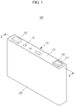
- FIG. 1 is a perspective view of a rechargeable battery according to an exemplary embodiment of the present invention
- FIG. 2 is a cross-sectional view of the rechargeable battery according to the exemplary embodiment shown in FIG. 1 , taken along the line II-II
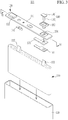
- FIG. 3 is an exploded perspective view of the rechargeable battery according to the exemplary embodiment shown in FIG. 1 .
- a rechargeable battery 100 includes an electrode assembly 110, a case 120, a cap assembly 130, a first current collecting member 161, a sealing member 150, and a first terminal 140.
- the rechargeable battery 100 according to the exemplary embodiment is exemplarily described as a prism-shaped lithium ion rechargeable battery.
- the present invention is not limited thereto, and the present invention may be applied to variously-shaped batteries such as a lithium polymer battery and a cylindrical battery.
- the electrode assembly 110 may include a first electrode 111 and a second electrode 112.
- the first electrode 111 may be a positive electrode
- the second electrode 112 may be a negative electrode.
- the first electrode 111 is a positive electrode
- the second electrode 112 is a negative electrode, and they may be changed depending on designs.
- the case 120 receives the electrode assembly 110.
- the case 120 may be formed in the shape of, for example, a cuboid.
- An opening is formed on an upper surface of the case 120.
- the case 120 may be made of, for example, a metal such as aluminum, stainless steel, and the like.
- the cap assembly 130 closes and seals the opened portion of the case 120.
- the cap assembly 120 includes a cap plate 131.
- the cap plate 131 covers the opened portion of the case 120.
- the cap plate 131 may have a shape of a plate that extends in one direction, but this is not restrictive.
- the first current collecting member 161 is disposed at a lower side and is connected with the first electrode 111. Since the first current collecting member 161 is connected with the first terminal 140, which will be described later, the first current collecting member 161 can electrically connect the first electrode 111 and the first terminal 140.
- an insulation member 170 may be disposed between the first current collecting member 161 and the cap plate 131.
- the insulation member 170 prevents the first current collecting member 161 and the cap plate 131 from being electrically connected with each other.
- the sealing member 150 is made of an insulation material and penetrates the cap plate 131 and the first current collecting member 161.
- a portion of the sealing member 150 penetrating the cap plate 131 and the first current collecting member 161 may be formed in the shape of a pipe having a hollow.
- the first terminal 140 which will be described later, may penetrate through the hollow.
- a sealing member 150 seals a space between the cap plate 131 and the first terminal 140. Further, the sealing member 150 prevents the first terminal 140 and the cap plate 131 from being electrically connected with each other.
- the first terminal 140 includes a base portion 141 that is fixed to an outer side of the cap plate 131, and an extension portion 142 that penetrates the sealing member 150.
- the first terminal 140 may be electrically connected with the first electrode 111 by the first current collecting member 161.
- the base portion 141 and the extension portion 142 of the first terminal 140 may be formed as a single body. That is, the first terminal 140 may be a single member rather than an assembly of a plurality of parts.
- the extension portion 142 of the first terminal 140 is formed to penetrate the sealing member 150 such that the first current collecting member 161 is fixed to the cap assembly 130.
- the base portion 141 is formed with a size that corresponds to an upper surface of the sealing member 150.
- the base portion 141 may be similar in size to the upper surface of the sealing member 150, or may be smaller than the sealing member 150.
- the base portion 141 may be formed in the shape of a rectangular plate, but this is not restrictive.
- the extension portion 142 extends from a bottom side of the base portion 141 so as to penetrate the sealing member 150.
- the extension portion 142 is provided to fix the first current collecting member 161 to the cap assembly 130.
- a through-hole 134 through which the extension portion 142 penetrates may be formed in the cap plate 131.
- the extension portion 142 and the base portion 141 may be made of a conductive material. Accordingly, the first current collecting member 161, the extension portion 143, and the base portion 141 may have the same polarity. Meanwhile, the base portion 141 and the extension portion 142 may be made of the same material.
- a lower end of the extension portion 142 is connected to the first current collecting member 161.
- a hole through which the extension portion 142 penetrates may be formed in the sealing member 150.
- the sealing member 150 may penetrate through the through-hole 134 formed in the first current collecting member 161.
- An interior diameter of the hole formed in the sealing member 150 may be relatively larger than or similar to a diameter of the extension portion 143.
- a rivet fastening method in which a user inserts the extension portion 142 into a hole formed in the first current collecting member 161 and then processes an end portion of the extension portion 142 by using an additional tool, may be used.
- this is not restrictive.
- a terminal is formed by combining a plurality of parts, but the rechargeable battery 100 according to the exemplary embodiment of the present invention is provided with the first terminal 140, which is formed as a single body and includes the extension portion 142 and the base portion 141, such that durability with respect to vibration can be significantly improved.
- the first terminal 140 of the rechargeable battery 100 according to the exemplary embodiment of the present invention is provided as a single body, a manufacturing process can be more simplified. Accordingly, manufacturing costs can be saved.
- FIG. 4 is a view of the cap assembly in the rechargeable battery according to the exemplary embodiment shown in FIG. 3 , taken along the line IV-IV.
- the cap assembly 130 in the rechargeable battery 100 may further include a coupling portion 133.
- the coupling portion 133 is integrally formed with the cap plate 131.
- the coupling portion 133 protrudes from a bottom side to which a second current collecting member 162 is coupled in the cap plate 131 and thus penetrates the second current collecting member 162.
- the coupling portion 133 may exemplarily be cylindrical.
- the second current collecting member 162 is connected with the second electrode 112 (refer to FIG. 3 ) of the electrode assembly 110 (refer to FIG. 3 ).
- the second current collecting member 162 is connected with the cap assembly 130 by the coupling portion 133.
- the cap assembly 130 may have negative polarity.
- the cap assembly 130 may have positive polarity.
- the coupling portion 133 enables the second current collecting member 162 to be fixed to the cap plate 131.
- a method for coupling the second current collecting member 162 to the cap plate 131 by the coupling portion 133 a rivet fastening method in which a user inserts the coupling portion 133 into a hole formed in the second current collecting member 162 and then processes an end portion of the coupling portion 133 by using an additional tool, may be used.
- this is not restrictive.
- the coupling portion 133 is integrally formed with the cap plate 131, and accordingly, the coupling portion 133 can be formed together when the cap plate 131 is formed.
- the manufacturing process can be more simplified compared to a structure in which a coupling portion and a cap plate are separately manufactured and then coupled together.
- portions where parts are coupled to each other are reduced in the rechargeable battery 100 (refer to FIG. 3 ) according to the exemplary embodiment of the present invention, and accordingly, resistance to vibration can be improved.
- the cap assembly 130 may further include a second terminal 132.
- the second terminal 132 is integrally formed with the cap plate 131, and protrudes from a portion of a top surface of the cap plate 131.
- the second terminal 132 may be disposed adjacent to the second current collecting member 162.
- the cap assembly 130 may have positive polarity or negative polarity by the second current collecting member 162, and thus the second terminal 132 integrally formed with the cap assembly 130 may also have positive polarity or negative polarity.
- the second terminal 132 may be electrically connected to a positive connection portion of the vehicle and the first terminal 140 may be electrically connected to a negative connection portion of the vehicle.
- the second terminal 132 is integrally formed with the cap plate 131, the second terminal 132 can be formed together when the cap plate 131 is manufactured.
Landscapes
- Chemical & Material Sciences (AREA)
- Chemical Kinetics & Catalysis (AREA)
- Electrochemistry (AREA)
- General Chemical & Material Sciences (AREA)
- Engineering & Computer Science (AREA)
- Manufacturing & Machinery (AREA)
- Materials Engineering (AREA)
- Connection Of Batteries Or Terminals (AREA)
- Sealing Battery Cases Or Jackets (AREA)
- Battery Mounting, Suspending (AREA)
Abstract
Description
- The present invention relates to a rechargeable battery.
- Unlike a primary battery that cannot be charged, a rechargeable battery can be charged and discharged. Low-capacity rechargeable batteries are used as power supplies for small electronic devices, such as cellular phones, notebook computers, and camcorders, while high-capacity rechargeable batteries are used as power supplies for hybrid vehicles and the like.
- In general, the rechargeable battery includes a case where an electrode assembly is received and a cap assembly that closes and seals the case. A positive terminal and a negative terminal may be formed on an upper side of the cap assembly.
- Assembly of such a rechargeable battery can connect an uncoated region formed at one side of the electrode assembly to a current collecting member coupled to the cap assembly. Such a rechargeable battery can be manufactured by coupling various parts.
- Meanwhile, when the rechargeable battery is installed in a vehicle, parts may be released from the coupled portion due to vibration that is generated when the vehicle is driven. In addition, there is a need to simplify a manufacturing process by reducing the number of assembled parts so as to reduce manufacturing cost of the rechargeable battery.
- An exemplary embodiment of the present invention has been made in an effort to provide a rechargeable battery that can be easily assembled.
- In addition, an exemplary embodiment of the present invention provides a rechargeable battery of which resistance with respect to vibration can be improved.
- A rechargeable battery according to one aspect of the present invention includes: an electrode assembly that includes a first electrode and a second electrode; a case of which one side is opened, and that receives the electrode assembly; a cap assembly that includes a cap plate covering the opened portion of the case; a first current collecting member that is disposed at a lower side of the cap assembly and is thus connected with the first electrode; a sealing member that is made of an insulation material and penetrates the cap plate and the first current collecting member; and a first terminal in which a base portion fixed to an outer side of the cap plate and an extension portion formed to penetrate the sealing member such that first current collecting member is fixed to the cap assembly are formed as a single body.
- The base portion may have a size that corresponds to an upper surface of the sealing member, and the extension portion may extend from a bottom side of the base portion and penetrate the sealing member such that the first current collecting member is fixed to the cap assembly.
- The base portion and the extension portion may be made of the same material.
- The cap assembly may further include a coupling portion that is integrally formed with the cap plate, and protrudes from a bottom side to which the second current collecting member is coupled in the cap plate and thus penetrates the second current collecting member..
- The cap assembly may further include a second terminal that is integrally formed with the cap plate and protrudes from a portion of a top surface of the cap plate.
- The second terminal may be disposed adjacent to the second current collecting member.
- The rechargeable battery according to an exemplary embodiment of the present invention is provided with an integrally formed first terminal such that durability with respect to vibration can be significantly improved. In addition, a first terminal of a conventional rechargeable battery is formed by assembling a plurality of parts, but the rechargeable battery according to the exemplary embodiment of the present invention uses the integrally formed first terminal so that a manufacturing process can be more simplified. Accordingly, manufacturing cost can be saved.
-
-
FIG. 1 is a perspective view of a rechargeable battery according to an exemplary embodiment of the present invention. -
FIG. 2 is a cross-sectional view of the rechargeable battery of the exemplary embodiment shown inFIG. 1 , taken along the line II-II. -
FIG. 3 is an exploded perspective view of the rechargeable battery according to the exemplary embodiment of the present invention shown inFIG. 1 . -
FIG. 4 is a view of the cap assembly in the rechargeable battery according to the exemplary embodiment shown inFIG. 3 , taken along the line IV-IV. - Hereinafter, the present invention will be described more fully with reference to the accompanying drawings, in which exemplary embodiments of the invention are shown. As those skilled in the art would realize, the described embodiments may be modified in various different ways, all without departing from the scope of the present invention.
- The drawings and description are to be regarded as illustrative in nature and not restrictive. Like reference numerals designate like elements throughout the specification.
- In several exemplary embodiments, components having the same configuration will be described representatively in a first exemplary embodiment by the same reference numerals. In exemplary embodiments other than the first exemplary embodiment, only configurations different from those of the first exemplary embodiment will be described.
- Throughout this specification and the claims that follow, when it is described that an element is "coupled" to another element, the element may be "directly coupled" to the other element or "electrically coupled" to the other element through a third element. In addition, unless explicitly described to the contrary, the word "comprise" and variations such as "comprises" or "comprising" will be understood to imply the inclusion of stated elements but not the exclusion of any other elements.
-
FIG. 1 is a perspective view of a rechargeable battery according to an exemplary embodiment of the present invention,FIG. 2 is a cross-sectional view of the rechargeable battery according to the exemplary embodiment shown inFIG. 1 , taken along the line II-II, andFIG. 3 is an exploded perspective view of the rechargeable battery according to the exemplary embodiment shown inFIG. 1 . - Referring to
FIG. 1 to FIG. 3 , arechargeable battery 100 according to an exemplary embodiment of the present invention includes anelectrode assembly 110, acase 120, acap assembly 130, a firstcurrent collecting member 161, asealing member 150, and afirst terminal 140. - The
rechargeable battery 100 according to the exemplary embodiment is exemplarily described as a prism-shaped lithium ion rechargeable battery. However, the present invention is not limited thereto, and the present invention may be applied to variously-shaped batteries such as a lithium polymer battery and a cylindrical battery. - The
electrode assembly 110 may include afirst electrode 111 and asecond electrode 112. Thefirst electrode 111 may be a positive electrode, and thesecond electrode 112 may be a negative electrode. However, it is not restrictive that thefirst electrode 111 is a positive electrode and thesecond electrode 112 is a negative electrode, and they may be changed depending on designs. - One side of the
case 120 may be opened. Thecase 120 receives theelectrode assembly 110. Thus, thecase 120 may be formed in the shape of, for example, a cuboid. An opening is formed on an upper surface of thecase 120. Thecase 120 may be made of, for example, a metal such as aluminum, stainless steel, and the like. - The
cap assembly 130 closes and seals the opened portion of thecase 120. For closing and sealing the opened portion of thecase 120, thecap assembly 120 includes acap plate 131. Thecap plate 131 covers the opened portion of thecase 120. Thecap plate 131 may have a shape of a plate that extends in one direction, but this is not restrictive. - The first
current collecting member 161 is disposed at a lower side and is connected with thefirst electrode 111. Since the firstcurrent collecting member 161 is connected with thefirst terminal 140, which will be described later, the firstcurrent collecting member 161 can electrically connect thefirst electrode 111 and thefirst terminal 140. - Meanwhile, an
insulation member 170 may be disposed between the firstcurrent collecting member 161 and thecap plate 131. Theinsulation member 170 prevents the firstcurrent collecting member 161 and thecap plate 131 from being electrically connected with each other. - The sealing
member 150 is made of an insulation material and penetrates thecap plate 131 and the firstcurrent collecting member 161. For this purpose, a portion of the sealingmember 150 penetrating thecap plate 131 and the firstcurrent collecting member 161 may be formed in the shape of a pipe having a hollow. - Accordingly, the
first terminal 140, which will be described later, may penetrate through the hollow. Such a sealingmember 150 seals a space between thecap plate 131 and thefirst terminal 140. Further, the sealingmember 150 prevents thefirst terminal 140 and thecap plate 131 from being electrically connected with each other. - The
first terminal 140 includes abase portion 141 that is fixed to an outer side of thecap plate 131, and anextension portion 142 that penetrates thesealing member 150. Thefirst terminal 140 may be electrically connected with thefirst electrode 111 by the first current collectingmember 161. Thebase portion 141 and theextension portion 142 of thefirst terminal 140 may be formed as a single body. That is, thefirst terminal 140 may be a single member rather than an assembly of a plurality of parts. Theextension portion 142 of thefirst terminal 140 is formed to penetrate the sealingmember 150 such that the first current collectingmember 161 is fixed to thecap assembly 130. - Shapes and structures of the
base portion 141 and theextension potion 142 that form thefirst terminal 140 will be described hereinafter in detail. - The
base portion 141 is formed with a size that corresponds to an upper surface of the sealingmember 150. Thebase portion 141 may be similar in size to the upper surface of the sealingmember 150, or may be smaller than the sealingmember 150. When the upper surface of the sealingmember 150 is formed in the shape of a rectangle, thebase portion 141 may be formed in the shape of a rectangular plate, but this is not restrictive. - The
extension portion 142 extends from a bottom side of thebase portion 141 so as to penetrate the sealingmember 150. Theextension portion 142 is provided to fix the first current collectingmember 161 to thecap assembly 130. For this purpose, a through-hole 134 through which theextension portion 142 penetrates may be formed in thecap plate 131. - The
extension portion 142 and thebase portion 141 may be made of a conductive material. Accordingly, the first current collectingmember 161, the extension portion 143, and thebase portion 141 may have the same polarity. Meanwhile, thebase portion 141 and theextension portion 142 may be made of the same material. - A lower end of the
extension portion 142 is connected to the first current collectingmember 161. A hole through which theextension portion 142 penetrates may be formed in the sealingmember 150. In addition, the sealingmember 150 may penetrate through the through-hole 134 formed in the first current collectingmember 161. An interior diameter of the hole formed in the sealingmember 150 may be relatively larger than or similar to a diameter of the extension portion 143. - As a method for coupling the first current collecting
member 161 to thecap assembly 130 by theextension portion 142, a rivet fastening method in which a user inserts theextension portion 142 into a hole formed in the first current collectingmember 161 and then processes an end portion of theextension portion 142 by using an additional tool, may be used. However, this is not restrictive. - In a conventional rechargeable battery, a terminal is formed by combining a plurality of parts, but the
rechargeable battery 100 according to the exemplary embodiment of the present invention is provided with thefirst terminal 140, which is formed as a single body and includes theextension portion 142 and thebase portion 141, such that durability with respect to vibration can be significantly improved. - In addition, since the
first terminal 140 of therechargeable battery 100 according to the exemplary embodiment of the present invention is provided as a single body, a manufacturing process can be more simplified. Accordingly, manufacturing costs can be saved. -
FIG. 4 is a view of the cap assembly in the rechargeable battery according to the exemplary embodiment shown inFIG. 3 , taken along the line IV-IV. - Referring to
FIG. 4 , thecap assembly 130 in therechargeable battery 100 according to the exemplary embodiment of the present invention may further include acoupling portion 133. - The
coupling portion 133 is integrally formed with thecap plate 131. Thecoupling portion 133 protrudes from a bottom side to which a second current collectingmember 162 is coupled in thecap plate 131 and thus penetrates the second current collectingmember 162. Thecoupling portion 133 may exemplarily be cylindrical. - The second current collecting
member 162 is connected with the second electrode 112 (refer toFIG. 3 ) of the electrode assembly 110 (refer toFIG. 3 ). The second current collectingmember 162 is connected with thecap assembly 130 by thecoupling portion 133. Thus, when the second electrode 112 (refer toFIG. 3 ) is a negative electrode, thecap assembly 130 may have negative polarity. Alternatively, when the second electrode 112 (refer toFIG. 3 ) is a positive electrode, thecap assembly 130 may have positive polarity. - The
coupling portion 133 enables the second current collectingmember 162 to be fixed to thecap plate 131. As a method for coupling the second current collectingmember 162 to thecap plate 131 by thecoupling portion 133, a rivet fastening method in which a user inserts thecoupling portion 133 into a hole formed in the second current collectingmember 162 and then processes an end portion of thecoupling portion 133 by using an additional tool, may be used. However, this is not restrictive. - As described, the
coupling portion 133 is integrally formed with thecap plate 131, and accordingly, thecoupling portion 133 can be formed together when thecap plate 131 is formed. Thus, when the rechargeable battery 100 (refer toFIG. 3 ) according to the exemplary embodiment of the present invention is manufactured, the manufacturing process can be more simplified compared to a structure in which a coupling portion and a cap plate are separately manufactured and then coupled together. - In addition, portions where parts are coupled to each other are reduced in the rechargeable battery 100 (refer to
FIG. 3 ) according to the exemplary embodiment of the present invention, and accordingly, resistance to vibration can be improved. - The
cap assembly 130 may further include asecond terminal 132. - The
second terminal 132 is integrally formed with thecap plate 131, and protrudes from a portion of a top surface of thecap plate 131. Thesecond terminal 132 may be disposed adjacent to the second current collectingmember 162. - As described above, the
cap assembly 130 may have positive polarity or negative polarity by the second current collectingmember 162, and thus thesecond terminal 132 integrally formed with thecap assembly 130 may also have positive polarity or negative polarity. - While the rechargeable battery 100 (refer to
FIG. 3 ) is installed in a vehicle while thesecond terminal 132 has positive polarity and thefirst terminal 140 has negative polarity in the rechargeable battery 100 (refer toFIG. 3 ) according to the exemplary embodiment of the present invention, thesecond terminal 132 may be electrically connected to a positive connection portion of the vehicle and thefirst terminal 140 may be electrically connected to a negative connection portion of the vehicle. - Since the
second terminal 132 is integrally formed with thecap plate 131, thesecond terminal 132 can be formed together when thecap plate 131 is manufactured. - While this invention has been described in connection with what is presently considered to be practical exemplary embodiments, it is to be understood that the invention is not limited to the disclosed embodiments, but, on the contrary, is intended to cover various modifications and equivalent arrangements included within the scope of the appended claims. It will be understood by those skilled in the art that various changes in form and detail may be made without departing from the scope of the present invention. Accordingly, the true scope of the present invention should be determined by the technical idea of the appended claims.
<Description of symbols> 100: rechargeable battery 110: electrode assembly 111: first electrode 112: second electrode 120: case 130: cap assembly 131: cap plate 132: second terminal 133: coupling portion 134: through-hole 140: first terminal 141: base portion 142: extension portion 150: sealing member 161: first current collecting member 162: second current collecting member 170: insulation member
Claims (6)
- A rechargeable battery comprising:an electrode assembly that includes a first electrode and a second electrode;a case of which one side is opened, and that receives the electrode assembly;a cap assembly that includes a cap plate covering the opened portion of the case;a first current collecting member that is disposed at a lower side of the cap assembly and is thus connected with the first electrode;a sealing member that is made of an insulation material and penetrates the cap plate and the first current collecting member; anda first terminal in which a base portion fixed to an outer side of the cap plate and an extension portion formed to penetrate the sealing member such that first current collecting member is fixed to the cap assembly are formed as a single body.
- The rechargeable battery of claim 1, wherein the base portion has a size that corresponds to an upper surface of the sealing member, and
the extension portion extends from a bottom side of the base portion and penetrates the sealing member such that the first current collecting member is fixed to the cap assembly. - The rechargeable battery of claim 1, wherein the base portion and the extension portion are made of the same material.
- The rechargeable battery of claim 1, wherein the cap assembly further comprises a coupling portion that is integrally formed with the cap plate, and protrudes from a bottom side to which the second current collecting member is coupled in the cap plate and thus penetrates the second current collecting member.
- The rechargeable battery of claim 1, wherein the cap assembly further comprises a second terminal that is integrally formed with the cap plate and protrudes from a portion of a top surface of the cap plate.
- The rechargeable battery of claim 4, wherein the second terminal is disposed adjacent to the second current collecting member.
Applications Claiming Priority (2)
| Application Number | Priority Date | Filing Date | Title |
|---|---|---|---|
| KR1020160088231A KR102207903B1 (en) | 2016-07-12 | 2016-07-12 | Rechargeable battery |
| PCT/KR2017/005372 WO2018012728A1 (en) | 2016-07-12 | 2017-05-24 | Rechargeable battery |
Publications (3)
| Publication Number | Publication Date |
|---|---|
| EP3486990A1 true EP3486990A1 (en) | 2019-05-22 |
| EP3486990A4 EP3486990A4 (en) | 2020-01-01 |
| EP3486990B1 EP3486990B1 (en) | 2023-07-19 |
Family
ID=60951828
Family Applications (1)
| Application Number | Title | Priority Date | Filing Date |
|---|---|---|---|
| EP17827802.4A Active EP3486990B1 (en) | 2016-07-12 | 2017-05-24 | Rechargeable battery |
Country Status (7)
| Country | Link |
|---|---|
| US (1) | US11133547B2 (en) |
| EP (1) | EP3486990B1 (en) |
| KR (1) | KR102207903B1 (en) |
| CN (1) | CN109478682B (en) |
| HU (1) | HUE063332T2 (en) |
| PL (1) | PL3486990T3 (en) |
| WO (1) | WO2018012728A1 (en) |
Cited By (1)
| Publication number | Priority date | Publication date | Assignee | Title |
|---|---|---|---|---|
| EP3916831A4 (en) * | 2019-01-26 | 2022-04-06 | BYD Company Limited | Battery unit, battery module and automobile |
Family Cites Families (29)
| Publication number | Priority date | Publication date | Assignee | Title |
|---|---|---|---|---|
| JP3547927B2 (en) * | 1996-07-10 | 2004-07-28 | 三洋電機株式会社 | Alkaline storage battery and method for manufacturing the same |
| JP4136223B2 (en) | 1999-09-21 | 2008-08-20 | 松下電器産業株式会社 | Secondary battery |
| JP4356314B2 (en) * | 2002-12-20 | 2009-11-04 | パナソニック株式会社 | Battery and battery pack |
| JP2004303500A (en) * | 2003-03-31 | 2004-10-28 | Sanyo Electric Co Ltd | Square battery |
| KR100561308B1 (en) | 2004-05-31 | 2006-03-15 | 삼성에스디아이 주식회사 | Secondary Battery |
| KR100854235B1 (en) | 2007-09-03 | 2008-08-25 | 삼성에스디아이 주식회사 | Can type lithium secondary battery |
| JP5213030B2 (en) | 2008-04-17 | 2013-06-19 | 日立マクセル株式会社 | Sealed battery manufacturing method and sealed battery |
| KR101084221B1 (en) | 2009-10-30 | 2011-11-17 | 에스비리모티브 주식회사 | Secondary battery |
| KR101084056B1 (en) * | 2010-07-21 | 2011-11-16 | 에스비리모티브 주식회사 | Rechargeable battery |
| US8951663B2 (en) | 2010-11-15 | 2015-02-10 | Samsung Sdi Co., Ltd. | Secondary battery |
| KR101222267B1 (en) | 2010-12-09 | 2013-01-15 | 로베르트 보쉬 게엠베하 | Secondary battery |
| KR101222269B1 (en) | 2010-12-27 | 2013-01-15 | 로베르트 보쉬 게엠베하 | Rechargeable battery and Battery Pack |
| US8632912B2 (en) * | 2011-04-14 | 2014-01-21 | Gs Yuasa International Ltd. | Battery including baffling member and sealing material that seals auxiliary terminal to lid plate |
| US8748034B2 (en) * | 2011-04-14 | 2014-06-10 | Gs Yuasa International Ltd. | Battery including baffling member including one of projecting portion and recessed portion extending from lid plate |
| JP5765062B2 (en) * | 2011-06-06 | 2015-08-19 | 株式会社Gsユアサ | Battery, power supply device, battery driving system, and method for detecting expansion of battery |
| US9634299B2 (en) | 2011-09-06 | 2017-04-25 | Samsung Sdi Co., Ltd. | Rechargeable battery |
| KR101724010B1 (en) * | 2011-10-19 | 2017-04-07 | 삼성에스디아이 주식회사 | Rechargeable battery |
| JP6175758B2 (en) | 2011-11-29 | 2017-08-09 | 株式会社Gsユアサ | Electricity storage element |
| US20130196219A1 (en) * | 2012-02-01 | 2013-08-01 | Robert Bosch Gmbh | Rechargeable battery |
| KR101698767B1 (en) * | 2013-01-28 | 2017-01-23 | 삼성에스디아이 주식회사 | Secondary battery |
| KR20140124247A (en) * | 2013-04-16 | 2014-10-24 | 삼성에스디아이 주식회사 | Rechargeable battery |
| US20140342198A1 (en) * | 2013-05-15 | 2014-11-20 | Samsung Sdi Co., Ltd. | Secondary battery |
| JP2015032465A (en) * | 2013-08-02 | 2015-02-16 | 株式会社Gsユアサ | Power storage element |
| KR101775545B1 (en) * | 2013-10-08 | 2017-09-06 | 삼성에스디아이 주식회사 | Rechargeable battery having short protrusion |
| US9225002B2 (en) * | 2013-10-24 | 2015-12-29 | Samsung Sdi Co., Ltd. | Rechargeable battery having fuse unit |
| JP5796623B2 (en) * | 2013-12-13 | 2015-10-21 | 株式会社Gsユアサ | battery |
| KR101689217B1 (en) | 2013-12-23 | 2016-12-23 | 삼성에스디아이 주식회사 | Secondary battery comprising intergral terminal unit and secondary battery module |
| KR102251330B1 (en) | 2014-11-19 | 2021-05-13 | 삼성에스디아이 주식회사 | Secondary Battery |
| JP6260876B2 (en) * | 2016-01-27 | 2018-01-17 | 株式会社Gsユアサ | Battery and manufacturing method thereof |
-
2016
- 2016-07-12 KR KR1020160088231A patent/KR102207903B1/en active IP Right Grant
-
2017
- 2017-05-24 EP EP17827802.4A patent/EP3486990B1/en active Active
- 2017-05-24 WO PCT/KR2017/005372 patent/WO2018012728A1/en unknown
- 2017-05-24 HU HUE17827802A patent/HUE063332T2/en unknown
- 2017-05-24 PL PL17827802.4T patent/PL3486990T3/en unknown
- 2017-05-24 US US16/312,941 patent/US11133547B2/en active Active
- 2017-05-24 CN CN201780043152.1A patent/CN109478682B/en active Active
Cited By (2)
| Publication number | Priority date | Publication date | Assignee | Title |
|---|---|---|---|---|
| EP3916831A4 (en) * | 2019-01-26 | 2022-04-06 | BYD Company Limited | Battery unit, battery module and automobile |
| US11824213B2 (en) | 2019-01-26 | 2023-11-21 | Byd Company Limited | Battery unit, battery module and vehicle |
Also Published As
| Publication number | Publication date |
|---|---|
| US11133547B2 (en) | 2021-09-28 |
| US20190221792A1 (en) | 2019-07-18 |
| KR102207903B1 (en) | 2021-01-25 |
| PL3486990T3 (en) | 2024-02-05 |
| EP3486990B1 (en) | 2023-07-19 |
| KR20180007242A (en) | 2018-01-22 |
| HUE063332T2 (en) | 2024-01-28 |
| CN109478682A (en) | 2019-03-15 |
| WO2018012728A1 (en) | 2018-01-18 |
| EP3486990A4 (en) | 2020-01-01 |
| CN109478682B (en) | 2022-12-02 |
Similar Documents
| Publication | Publication Date | Title |
|---|---|---|
| CN106784576B (en) | Secondary battery | |
| EP3109926B1 (en) | Rechargeable battery and rechargeable battery module | |
| EP2958162B1 (en) | Secondary battery | |
| KR101217071B1 (en) | Rechargeable battery | |
| EP2757614B1 (en) | Secondary battery and assembling method thereof | |
| EP3007246B1 (en) | Rechargeable battery | |
| EP3531476A1 (en) | Secondary battery and module for same | |
| US20120141845A1 (en) | Rechargeable battery | |
| EP3082178B1 (en) | Rechargeable battery | |
| US20140308575A1 (en) | Rechargeable battery | |
| KR20190027673A (en) | Secondary Battery | |
| US20150214536A1 (en) | Secondary battery | |
| EP2175506B1 (en) | Secondary battery | |
| CN104882571A (en) | Secondary battery and cap assembly for the secondary battery | |
| EP2830121B1 (en) | Rechargeable battery | |
| US9419252B2 (en) | Rechargeable battery | |
| US9515343B2 (en) | Rechargeable battery | |
| EP3486990A1 (en) | Rechargeable battery | |
| CN106058081B (en) | Rechargeable battery and method of manufacturing the same | |
| EP3926739A1 (en) | Rechargeable battery | |
| KR101733745B1 (en) | Rechargeable battery | |
| US9190637B2 (en) | Rechargeable battery | |
| EP3001481A1 (en) | Rechargeable battery | |
| US10957885B2 (en) | Rechargeable battery having case |
Legal Events
| Date | Code | Title | Description |
|---|---|---|---|
| STAA | Information on the status of an ep patent application or granted ep patent |
Free format text: STATUS: THE INTERNATIONAL PUBLICATION HAS BEEN MADE |
|
| PUAI | Public reference made under article 153(3) epc to a published international application that has entered the european phase |
Free format text: ORIGINAL CODE: 0009012 |
|
| STAA | Information on the status of an ep patent application or granted ep patent |
Free format text: STATUS: REQUEST FOR EXAMINATION WAS MADE |
|
| 17P | Request for examination filed |
Effective date: 20190103 |
|
| AK | Designated contracting states |
Kind code of ref document: A1 Designated state(s): AL AT BE BG CH CY CZ DE DK EE ES FI FR GB GR HR HU IE IS IT LI LT LU LV MC MK MT NL NO PL PT RO RS SE SI SK SM TR |
|
| AX | Request for extension of the european patent |
Extension state: BA ME |
|
| DAV | Request for validation of the european patent (deleted) | ||
| DAX | Request for extension of the european patent (deleted) | ||
| A4 | Supplementary search report drawn up and despatched |
Effective date: 20191202 |
|
| RIC1 | Information provided on ipc code assigned before grant |
Ipc: H01M 2/04 20060101ALI20191126BHEP Ipc: H01M 10/0525 20100101AFI20191126BHEP Ipc: H01M 2/30 20060101ALI20191126BHEP Ipc: H01M 10/058 20100101ALI20191126BHEP |
|
| REG | Reference to a national code |
Ref country code: DE Ref legal event code: R079 Ref document number: 602017071572 Country of ref document: DE Free format text: PREVIOUS MAIN CLASS: H01M0010052500 Ipc: H01M0050176000 Ref country code: DE Ref legal event code: R079 Free format text: PREVIOUS MAIN CLASS: H01M0010052500 Ipc: H01M0050176000 |
|
| GRAP | Despatch of communication of intention to grant a patent |
Free format text: ORIGINAL CODE: EPIDOSNIGR1 |
|
| STAA | Information on the status of an ep patent application or granted ep patent |
Free format text: STATUS: GRANT OF PATENT IS INTENDED |
|
| RIC1 | Information provided on ipc code assigned before grant |
Ipc: H01M 50/553 20210101ALI20230228BHEP Ipc: H01M 50/55 20210101ALI20230228BHEP Ipc: H01M 50/188 20210101ALI20230228BHEP Ipc: H01M 50/176 20210101AFI20230228BHEP |
|
| INTG | Intention to grant announced |
Effective date: 20230317 |
|
| GRAS | Grant fee paid |
Free format text: ORIGINAL CODE: EPIDOSNIGR3 |
|
| GRAA | (expected) grant |
Free format text: ORIGINAL CODE: 0009210 |
|
| STAA | Information on the status of an ep patent application or granted ep patent |
Free format text: STATUS: THE PATENT HAS BEEN GRANTED |
|
| AK | Designated contracting states |
Kind code of ref document: B1 Designated state(s): AL AT BE BG CH CY CZ DE DK EE ES FI FR GB GR HR HU IE IS IT LI LT LU LV MC MK MT NL NO PL PT RO RS SE SI SK SM TR |
|
| REG | Reference to a national code |
Ref country code: GB Ref legal event code: FG4D |
|
| REG | Reference to a national code |
Ref country code: CH Ref legal event code: EP |
|
| REG | Reference to a national code |
Ref country code: DE Ref legal event code: R096 Ref document number: 602017071572 Country of ref document: DE |
|
| REG | Reference to a national code |
Ref country code: IE Ref legal event code: FG4D |
|
| REG | Reference to a national code |
Ref country code: SE Ref legal event code: TRGR |
|
| REG | Reference to a national code |
Ref country code: LT Ref legal event code: MG9D |
|
| REG | Reference to a national code |
Ref country code: NL Ref legal event code: MP Effective date: 20230719 |
|
| REG | Reference to a national code |
Ref country code: AT Ref legal event code: MK05 Ref document number: 1590400 Country of ref document: AT Kind code of ref document: T Effective date: 20230719 |
|
| PG25 | Lapsed in a contracting state [announced via postgrant information from national office to epo] |
Ref country code: NL Free format text: LAPSE BECAUSE OF FAILURE TO SUBMIT A TRANSLATION OF THE DESCRIPTION OR TO PAY THE FEE WITHIN THE PRESCRIBED TIME-LIMIT Effective date: 20230719 |
|
| PG25 | Lapsed in a contracting state [announced via postgrant information from national office to epo] |
Ref country code: GR Free format text: LAPSE BECAUSE OF FAILURE TO SUBMIT A TRANSLATION OF THE DESCRIPTION OR TO PAY THE FEE WITHIN THE PRESCRIBED TIME-LIMIT Effective date: 20231020 |
|
| PG25 | Lapsed in a contracting state [announced via postgrant information from national office to epo] |
Ref country code: IS Free format text: LAPSE BECAUSE OF FAILURE TO SUBMIT A TRANSLATION OF THE DESCRIPTION OR TO PAY THE FEE WITHIN THE PRESCRIBED TIME-LIMIT Effective date: 20231119 |
|
| REG | Reference to a national code |
Ref country code: HU Ref legal event code: AG4A Ref document number: E063332 Country of ref document: HU |
|
| PG25 | Lapsed in a contracting state [announced via postgrant information from national office to epo] |
Ref country code: RS Free format text: LAPSE BECAUSE OF FAILURE TO SUBMIT A TRANSLATION OF THE DESCRIPTION OR TO PAY THE FEE WITHIN THE PRESCRIBED TIME-LIMIT Effective date: 20230719 Ref country code: PT Free format text: LAPSE BECAUSE OF FAILURE TO SUBMIT A TRANSLATION OF THE DESCRIPTION OR TO PAY THE FEE WITHIN THE PRESCRIBED TIME-LIMIT Effective date: 20231120 Ref country code: NO Free format text: LAPSE BECAUSE OF FAILURE TO SUBMIT A TRANSLATION OF THE DESCRIPTION OR TO PAY THE FEE WITHIN THE PRESCRIBED TIME-LIMIT Effective date: 20231019 Ref country code: LV Free format text: LAPSE BECAUSE OF FAILURE TO SUBMIT A TRANSLATION OF THE DESCRIPTION OR TO PAY THE FEE WITHIN THE PRESCRIBED TIME-LIMIT Effective date: 20230719 Ref country code: LT Free format text: LAPSE BECAUSE OF FAILURE TO SUBMIT A TRANSLATION OF THE DESCRIPTION OR TO PAY THE FEE WITHIN THE PRESCRIBED TIME-LIMIT Effective date: 20230719 Ref country code: IS Free format text: LAPSE BECAUSE OF FAILURE TO SUBMIT A TRANSLATION OF THE DESCRIPTION OR TO PAY THE FEE WITHIN THE PRESCRIBED TIME-LIMIT Effective date: 20231119 Ref country code: HR Free format text: LAPSE BECAUSE OF FAILURE TO SUBMIT A TRANSLATION OF THE DESCRIPTION OR TO PAY THE FEE WITHIN THE PRESCRIBED TIME-LIMIT Effective date: 20230719 Ref country code: GR Free format text: LAPSE BECAUSE OF FAILURE TO SUBMIT A TRANSLATION OF THE DESCRIPTION OR TO PAY THE FEE WITHIN THE PRESCRIBED TIME-LIMIT Effective date: 20231020 Ref country code: FI Free format text: LAPSE BECAUSE OF FAILURE TO SUBMIT A TRANSLATION OF THE DESCRIPTION OR TO PAY THE FEE WITHIN THE PRESCRIBED TIME-LIMIT Effective date: 20230719 Ref country code: AT Free format text: LAPSE BECAUSE OF FAILURE TO SUBMIT A TRANSLATION OF THE DESCRIPTION OR TO PAY THE FEE WITHIN THE PRESCRIBED TIME-LIMIT Effective date: 20230719 |
|
| REG | Reference to a national code |
Ref country code: DE Ref legal event code: R097 Ref document number: 602017071572 Country of ref document: DE |
|
| PG25 | Lapsed in a contracting state [announced via postgrant information from national office to epo] |
Ref country code: ES Free format text: LAPSE BECAUSE OF FAILURE TO SUBMIT A TRANSLATION OF THE DESCRIPTION OR TO PAY THE FEE WITHIN THE PRESCRIBED TIME-LIMIT Effective date: 20230719 |
|
| PG25 | Lapsed in a contracting state [announced via postgrant information from national office to epo] |
Ref country code: SM Free format text: LAPSE BECAUSE OF FAILURE TO SUBMIT A TRANSLATION OF THE DESCRIPTION OR TO PAY THE FEE WITHIN THE PRESCRIBED TIME-LIMIT Effective date: 20230719 Ref country code: RO Free format text: LAPSE BECAUSE OF FAILURE TO SUBMIT A TRANSLATION OF THE DESCRIPTION OR TO PAY THE FEE WITHIN THE PRESCRIBED TIME-LIMIT Effective date: 20230719 Ref country code: ES Free format text: LAPSE BECAUSE OF FAILURE TO SUBMIT A TRANSLATION OF THE DESCRIPTION OR TO PAY THE FEE WITHIN THE PRESCRIBED TIME-LIMIT Effective date: 20230719 Ref country code: EE Free format text: LAPSE BECAUSE OF FAILURE TO SUBMIT A TRANSLATION OF THE DESCRIPTION OR TO PAY THE FEE WITHIN THE PRESCRIBED TIME-LIMIT Effective date: 20230719 Ref country code: DK Free format text: LAPSE BECAUSE OF FAILURE TO SUBMIT A TRANSLATION OF THE DESCRIPTION OR TO PAY THE FEE WITHIN THE PRESCRIBED TIME-LIMIT Effective date: 20230719 Ref country code: CZ Free format text: LAPSE BECAUSE OF FAILURE TO SUBMIT A TRANSLATION OF THE DESCRIPTION OR TO PAY THE FEE WITHIN THE PRESCRIBED TIME-LIMIT Effective date: 20230719 Ref country code: SK Free format text: LAPSE BECAUSE OF FAILURE TO SUBMIT A TRANSLATION OF THE DESCRIPTION OR TO PAY THE FEE WITHIN THE PRESCRIBED TIME-LIMIT Effective date: 20230719 |
|
| PLBE | No opposition filed within time limit |
Free format text: ORIGINAL CODE: 0009261 |
|
| STAA | Information on the status of an ep patent application or granted ep patent |
Free format text: STATUS: NO OPPOSITION FILED WITHIN TIME LIMIT |
|
| PG25 | Lapsed in a contracting state [announced via postgrant information from national office to epo] |
Ref country code: IT Free format text: LAPSE BECAUSE OF FAILURE TO SUBMIT A TRANSLATION OF THE DESCRIPTION OR TO PAY THE FEE WITHIN THE PRESCRIBED TIME-LIMIT Effective date: 20230719 |
|
| 26N | No opposition filed |
Effective date: 20240422 |
|
| PGFP | Annual fee paid to national office [announced via postgrant information from national office to epo] |
Ref country code: GB Payment date: 20240425 Year of fee payment: 8 |
|
| PGFP | Annual fee paid to national office [announced via postgrant information from national office to epo] |
Ref country code: DE Payment date: 20240502 Year of fee payment: 8 |
|
| PG25 | Lapsed in a contracting state [announced via postgrant information from national office to epo] |
Ref country code: SI Free format text: LAPSE BECAUSE OF FAILURE TO SUBMIT A TRANSLATION OF THE DESCRIPTION OR TO PAY THE FEE WITHIN THE PRESCRIBED TIME-LIMIT Effective date: 20230719 |
|
| PGFP | Annual fee paid to national office [announced via postgrant information from national office to epo] |
Ref country code: FR Payment date: 20240509 Year of fee payment: 8 |
|
| PGFP | Annual fee paid to national office [announced via postgrant information from national office to epo] |
Ref country code: PL Payment date: 20240426 Year of fee payment: 8 |
|
| PGFP | Annual fee paid to national office [announced via postgrant information from national office to epo] |
Ref country code: SE Payment date: 20240429 Year of fee payment: 8 Ref country code: HU Payment date: 20240522 Year of fee payment: 8 |