EP3486973B1 - All-solid battery and method of manufacturing the same - Google Patents
All-solid battery and method of manufacturing the same Download PDFInfo
- Publication number
- EP3486973B1 EP3486973B1 EP18200223.8A EP18200223A EP3486973B1 EP 3486973 B1 EP3486973 B1 EP 3486973B1 EP 18200223 A EP18200223 A EP 18200223A EP 3486973 B1 EP3486973 B1 EP 3486973B1
- Authority
- EP
- European Patent Office
- Prior art keywords
- layer
- edge portion
- cathode
- anode
- electrolyte
- Prior art date
- Legal status (The legal status is an assumption and is not a legal conclusion. Google has not performed a legal analysis and makes no representation as to the accuracy of the status listed.)
- Active
Links
Images


Classifications
-
- H—ELECTRICITY
- H01—ELECTRIC ELEMENTS
- H01M—PROCESSES OR MEANS, e.g. BATTERIES, FOR THE DIRECT CONVERSION OF CHEMICAL ENERGY INTO ELECTRICAL ENERGY
- H01M10/00—Secondary cells; Manufacture thereof
- H01M10/04—Construction or manufacture in general
- H01M10/0404—Machines for assembling batteries
-
- H—ELECTRICITY
- H01—ELECTRIC ELEMENTS
- H01M—PROCESSES OR MEANS, e.g. BATTERIES, FOR THE DIRECT CONVERSION OF CHEMICAL ENERGY INTO ELECTRICAL ENERGY
- H01M10/00—Secondary cells; Manufacture thereof
- H01M10/05—Accumulators with non-aqueous electrolyte
- H01M10/058—Construction or manufacture
- H01M10/0585—Construction or manufacture of accumulators having only flat construction elements, i.e. flat positive electrodes, flat negative electrodes and flat separators
-
- H—ELECTRICITY
- H01—ELECTRIC ELEMENTS
- H01M—PROCESSES OR MEANS, e.g. BATTERIES, FOR THE DIRECT CONVERSION OF CHEMICAL ENERGY INTO ELECTRICAL ENERGY
- H01M10/00—Secondary cells; Manufacture thereof
- H01M10/04—Construction or manufacture in general
-
- H—ELECTRICITY
- H01—ELECTRIC ELEMENTS
- H01M—PROCESSES OR MEANS, e.g. BATTERIES, FOR THE DIRECT CONVERSION OF CHEMICAL ENERGY INTO ELECTRICAL ENERGY
- H01M10/00—Secondary cells; Manufacture thereof
- H01M10/04—Construction or manufacture in general
- H01M10/0413—Large-sized flat cells or batteries for motive or stationary systems with plate-like electrodes
-
- H—ELECTRICITY
- H01—ELECTRIC ELEMENTS
- H01M—PROCESSES OR MEANS, e.g. BATTERIES, FOR THE DIRECT CONVERSION OF CHEMICAL ENERGY INTO ELECTRICAL ENERGY
- H01M10/00—Secondary cells; Manufacture thereof
- H01M10/04—Construction or manufacture in general
- H01M10/0436—Small-sized flat cells or batteries for portable equipment
-
- H—ELECTRICITY
- H01—ELECTRIC ELEMENTS
- H01M—PROCESSES OR MEANS, e.g. BATTERIES, FOR THE DIRECT CONVERSION OF CHEMICAL ENERGY INTO ELECTRICAL ENERGY
- H01M10/00—Secondary cells; Manufacture thereof
- H01M10/05—Accumulators with non-aqueous electrolyte
- H01M10/052—Li-accumulators
- H01M10/0525—Rocking-chair batteries, i.e. batteries with lithium insertion or intercalation in both electrodes; Lithium-ion batteries
-
- H—ELECTRICITY
- H01—ELECTRIC ELEMENTS
- H01M—PROCESSES OR MEANS, e.g. BATTERIES, FOR THE DIRECT CONVERSION OF CHEMICAL ENERGY INTO ELECTRICAL ENERGY
- H01M10/00—Secondary cells; Manufacture thereof
- H01M10/05—Accumulators with non-aqueous electrolyte
- H01M10/056—Accumulators with non-aqueous electrolyte characterised by the materials used as electrolytes, e.g. mixed inorganic/organic electrolytes
-
- H—ELECTRICITY
- H01—ELECTRIC ELEMENTS
- H01M—PROCESSES OR MEANS, e.g. BATTERIES, FOR THE DIRECT CONVERSION OF CHEMICAL ENERGY INTO ELECTRICAL ENERGY
- H01M10/00—Secondary cells; Manufacture thereof
- H01M10/05—Accumulators with non-aqueous electrolyte
- H01M10/056—Accumulators with non-aqueous electrolyte characterised by the materials used as electrolytes, e.g. mixed inorganic/organic electrolytes
- H01M10/0561—Accumulators with non-aqueous electrolyte characterised by the materials used as electrolytes, e.g. mixed inorganic/organic electrolytes the electrolyte being constituted of inorganic materials only
- H01M10/0562—Solid materials
-
- H—ELECTRICITY
- H01—ELECTRIC ELEMENTS
- H01M—PROCESSES OR MEANS, e.g. BATTERIES, FOR THE DIRECT CONVERSION OF CHEMICAL ENERGY INTO ELECTRICAL ENERGY
- H01M4/00—Electrodes
- H01M4/02—Electrodes composed of, or comprising, active material
- H01M4/04—Processes of manufacture in general
- H01M4/0402—Methods of deposition of the material
- H01M4/0404—Methods of deposition of the material by coating on electrode collectors
-
- H—ELECTRICITY
- H01—ELECTRIC ELEMENTS
- H01M—PROCESSES OR MEANS, e.g. BATTERIES, FOR THE DIRECT CONVERSION OF CHEMICAL ENERGY INTO ELECTRICAL ENERGY
- H01M50/00—Constructional details or processes of manufacture of the non-active parts of electrochemical cells other than fuel cells, e.g. hybrid cells
- H01M50/10—Primary casings; Jackets or wrappings
- H01M50/116—Primary casings; Jackets or wrappings characterised by the material
-
- H—ELECTRICITY
- H01—ELECTRIC ELEMENTS
- H01M—PROCESSES OR MEANS, e.g. BATTERIES, FOR THE DIRECT CONVERSION OF CHEMICAL ENERGY INTO ELECTRICAL ENERGY
- H01M50/00—Constructional details or processes of manufacture of the non-active parts of electrochemical cells other than fuel cells, e.g. hybrid cells
- H01M50/10—Primary casings; Jackets or wrappings
- H01M50/116—Primary casings; Jackets or wrappings characterised by the material
- H01M50/121—Organic material
-
- H—ELECTRICITY
- H01—ELECTRIC ELEMENTS
- H01M—PROCESSES OR MEANS, e.g. BATTERIES, FOR THE DIRECT CONVERSION OF CHEMICAL ENERGY INTO ELECTRICAL ENERGY
- H01M50/00—Constructional details or processes of manufacture of the non-active parts of electrochemical cells other than fuel cells, e.g. hybrid cells
- H01M50/40—Separators; Membranes; Diaphragms; Spacing elements inside cells
- H01M50/403—Manufacturing processes of separators, membranes or diaphragms
-
- H—ELECTRICITY
- H01—ELECTRIC ELEMENTS
- H01M—PROCESSES OR MEANS, e.g. BATTERIES, FOR THE DIRECT CONVERSION OF CHEMICAL ENERGY INTO ELECTRICAL ENERGY
- H01M50/00—Constructional details or processes of manufacture of the non-active parts of electrochemical cells other than fuel cells, e.g. hybrid cells
- H01M50/40—Separators; Membranes; Diaphragms; Spacing elements inside cells
- H01M50/409—Separators, membranes or diaphragms characterised by the material
- H01M50/411—Organic material
- H01M50/414—Synthetic resins, e.g. thermoplastics or thermosetting resins
-
- H—ELECTRICITY
- H01—ELECTRIC ELEMENTS
- H01M—PROCESSES OR MEANS, e.g. BATTERIES, FOR THE DIRECT CONVERSION OF CHEMICAL ENERGY INTO ELECTRICAL ENERGY
- H01M50/00—Constructional details or processes of manufacture of the non-active parts of electrochemical cells other than fuel cells, e.g. hybrid cells
- H01M50/40—Separators; Membranes; Diaphragms; Spacing elements inside cells
- H01M50/489—Separators, membranes, diaphragms or spacing elements inside the cells, characterised by their physical properties, e.g. swelling degree, hydrophilicity or shut down properties
-
- H—ELECTRICITY
- H01—ELECTRIC ELEMENTS
- H01M—PROCESSES OR MEANS, e.g. BATTERIES, FOR THE DIRECT CONVERSION OF CHEMICAL ENERGY INTO ELECTRICAL ENERGY
- H01M4/00—Electrodes
- H01M4/02—Electrodes composed of, or comprising, active material
- H01M2004/021—Physical characteristics, e.g. porosity, surface area
-
- H—ELECTRICITY
- H01—ELECTRIC ELEMENTS
- H01M—PROCESSES OR MEANS, e.g. BATTERIES, FOR THE DIRECT CONVERSION OF CHEMICAL ENERGY INTO ELECTRICAL ENERGY
- H01M2300/00—Electrolytes
- H01M2300/0017—Non-aqueous electrolytes
- H01M2300/0065—Solid electrolytes
-
- Y—GENERAL TAGGING OF NEW TECHNOLOGICAL DEVELOPMENTS; GENERAL TAGGING OF CROSS-SECTIONAL TECHNOLOGIES SPANNING OVER SEVERAL SECTIONS OF THE IPC; TECHNICAL SUBJECTS COVERED BY FORMER USPC CROSS-REFERENCE ART COLLECTIONS [XRACs] AND DIGESTS
- Y02—TECHNOLOGIES OR APPLICATIONS FOR MITIGATION OR ADAPTATION AGAINST CLIMATE CHANGE
- Y02E—REDUCTION OF GREENHOUSE GAS [GHG] EMISSIONS, RELATED TO ENERGY GENERATION, TRANSMISSION OR DISTRIBUTION
- Y02E60/00—Enabling technologies; Technologies with a potential or indirect contribution to GHG emissions mitigation
- Y02E60/10—Energy storage using batteries
-
- Y—GENERAL TAGGING OF NEW TECHNOLOGICAL DEVELOPMENTS; GENERAL TAGGING OF CROSS-SECTIONAL TECHNOLOGIES SPANNING OVER SEVERAL SECTIONS OF THE IPC; TECHNICAL SUBJECTS COVERED BY FORMER USPC CROSS-REFERENCE ART COLLECTIONS [XRACs] AND DIGESTS
- Y02—TECHNOLOGIES OR APPLICATIONS FOR MITIGATION OR ADAPTATION AGAINST CLIMATE CHANGE
- Y02P—CLIMATE CHANGE MITIGATION TECHNOLOGIES IN THE PRODUCTION OR PROCESSING OF GOODS
- Y02P70/00—Climate change mitigation technologies in the production process for final industrial or consumer products
- Y02P70/50—Manufacturing or production processes characterised by the final manufactured product
Definitions
- the present disclosure relates to an all-solid battery and a method of manufacturing the same.
- lithium ion secondary batteries use liquid electrolytes, which are volatile and heat-sensitive, the energy density of lithium ion secondary batteries gradually increases, but lithium ion secondary batteries always entail the risk of ignition and explosion. Hence, an all-solid battery having low explosion risk and high thermal stability has been receiving attention.
- US 2014/0079992 A1 describes a bipolar electrode comprising a current collector, a cathode active material layer formed on a first surface of the current collector and an anode active material layer formed on a second surface of the current collector opposite to its first surface.
- the current collector has a larger surface area than the cathode active material layer and the anode active material layer.
- An edge portion of the current collector is covered by a reinforcing layer made from polyester, polypropylene, polystyrene, polyamide, polyvinyl chloride or polycarbonate.
- US 2017/0207482 A1 describes a method for manufacturing an all-solid-state battery.
- the present disclosure has been made keeping in mind the problems encountered in the related art, and the present disclosure is intended to provide an all-solid battery and a method of manufacturing the same, in which an edge portion of the all-solid battery may be more effectively insulated.
- the present invention provides a method of manufacturing an all-solid battery with the features of claim 1 and an all-solid battery with the features of claim 11.
- the baroplastic polymer may be contained in an amount of 50 volume% or more.
- the baroplastic polymer may exhibit baroplasticity at 50 °C or less and may have an average particle size of 10 - 100 ⁇ m.
- the baroplastic polymer may include a mixture of at least two selected from the group consisting of polystyrene (PS), polyisoprene (PI), poly(n-butyl acrylate) (PBA), poly(2-ethylhexyl acrylate) (PEHA), poly(pentyl methacrylate) (PPMA), poly(butyl methacrylate) (PBMA), polycarbonate (PC), poly(methyl methacrylate) (PMMA), poly(vinyl chloride) (PVC), poly(ethyl acrylate) (PEA), poly(ethyl methacrylate) (PEMA), and polybutadiene (PB).
- PS polystyrene
- PI polyisoprene
- PBA poly(n-butyl acrylate)
- PEHA poly(2-ethylhexyl acrylate)
- PEHA poly(pentyl methacrylate)
- PBMA poly(butyl methacrylate)
- the step of forming the insulation layer may include sealing the battery, in which the edge portion is coated with the baroplastic polymer, in a pouch and pressing the sealed pouch at 3 ton/m 2 to 5 to thus form the insulation layer.
- the cathode layer, the electrolyte layer and the anode layer may have the same area as each other, and the insulation layer of the edge portion may be formed on an edge portion in the external direction of each of the cathode layer, the electrolyte layer and the anode layer.
- the cathode layer may have a small area compared to the anode layer and the electrolyte layer, and the insulation layer of the edge portion may be formed on an edge portion of the cathode layer.
- the anode layer may have a small area compared to the cathode layer and the electrolyte layer, and the insulation layer of the edge portion may be formed on an edge portion of the anode layer.
- the electrolyte layer may have a small area compared to the anode layer and the cathode layer, and the insulation layer of the edge portion may be formed on an edge portion of the electrolyte layer.
- the anode layer or the cathode layer may have a large area compared to the remaining layers, and the insulation layer of the edge portion may be formed on an edge portion of each of the remaining layers, which have a smaller area.
- a short circuit of an edge portion of a battery can be fundamentally prevented from occurring as a result of breaking or stripping of electrodes, etc. by pressure during a pressing process at the time of battery fabrication.
- an insulation layer of the edge portion can be formed using a baroplastic polymer, and thus, even when some of the electrodes are stripped in the pressing process, the baroplastic polymer is shaped in the state of being mixed with such stripped materials, thereby effectively preventing stripping of the electrode edge portion and thus short-circuiting of the battery during the pressing process.
- an all-solid battery according to the present disclosure having a stacking structure in which an electrolyte layer is interposed between a cathode layer 1 and an anode layer 2, an edge portion of the battery has an insulation layer 4 using a baroplastic polymer material.
- the method of manufacturing the all-solid battery according to the present disclosure includes forming a cathode layer 1 and an anode layer 2, forming an electrolyte layer 3 between the cathode layer 1 and the anode layer 2, coating the edge portion with a baroplastic polymer material, and placing the stacking battery structure in a pouch and performing vacuum sealing and pressing, thereby manufacturing an all-solid battery in which the edge portion is insulated.
- Forming the cathode layer 1 or the anode layer 2 may be performed in a manner in which a current collector made of a metal, serving as a substrate, is coated with an anode composite slurry or a cathode composite slurry.
- the anode composite slurry contains an anode active material, which is typically used in the field of secondary batteries, such as silicon (Si), tin (Sn), or graphite.
- the cathode composite slurry contains a cathode active material, examples of the cathode active material including lithium nickel cobalt manganese (NCM) -based, lithium cobalt oxide (LCO)-based, lithium nickel cobalt aluminum (NCA)-based, and lithium iron phosphate (LFP)-based materials, which are typically used in the field of secondary batteries.
- the cathode active material including lithium nickel cobalt manganese (NCM) -based, lithium cobalt oxide (LCO)-based, lithium nickel cobalt aluminum (NCA)-based, and lithium iron phosphate (LFP)-based materials, which are typically used in the field of secondary batteries.
- the anode composite and the cathode composite respectively contain an anode active material and a cathode active material in combination with a conductive additive and a binder, and each of the anode composite and the cathode composite may be applied in the form of a slurry.
- the coating process may be performed using a process that is typically used in electrode coating, such as bar coating, gravure coating, or the like.
- An electrolyte layer 3 is interposed between the cathode layer 1 and the anode layer 2, which are manufactured as above, and the electrolyte layer 3 may be formed by subjecting an all-solid electrolyte comprising a sulfide or oxide material having ionic conductivity of 10 -3 s/cm or more to insertion through lamination or coating.
- the edge portion of the battery comprising the cathode layer 1, the electrolyte layer 3, and the anode layer 2, which are stacked, is coated with a baroplastic polymer material.
- the baroplastic polymer material may be a mixture in which the term for compressibility is negative in a compressible regular solution model.
- the baroplastic polymer may have compatibility at 50 °C or less, and a baroplastic polymer powder has an average particle size of 10 to 100 ⁇ m.
- the baroplastic polymer may be a mixture comprising at least two selected from among polystyrene (PS), polyisoprene (PI), poly(n-butyl acrylate) (PBA), poly(2-ethylhexyl acrylate) (PEHA), poly(pentyl methacrylate) (PPMA), poly(butyl methacrylate) (PBMA), polycarbonate (PC), poly(methyl methacrylate) (PMMA), poly(vinyl chloride) (PVC), poly(ethyl acrylate) (PEA), poly(ethyl methacrylate) (PEMA), and polybutadiene (PB), but is not limited thereto, so long as it is baroplastic under predetermined pressure.
- PS polystyrene
- PI polyisoprene
- PBA poly(n-butyl acrylate)
- PEHA poly(2-ethylhexyl acrylate)
- PEHA poly(pentyl methacryl
- the baroplastic polymer material is used to form the insulation layer 4 at the edge portion of the battery configured such that the cathode layer 1, the anode layer 2, and the electrolyte layer 3 are stacked.
- the baroplastic polymer material has to be positioned at the edge portion of the battery, and the baroplastic polymer material positioned at the edge portion is compressed under predetermined pressure, thus forming the insulation layer 4.
- cold isostatic pressing is applied upon the fabrication of an all-solid battery.
- forming the insulation layer 4 by compressing the baroplastic polymer material may be carried out through cold isostatic pressing.
- pressure is uniformly applied in all directions using a liquid at a low temperature.
- a pouch cell in which the stacked cell is placed in a pouch is positioned in a liquid-containing vessel, and pressure is uniformly applied to the pouch cell in all directions.
- the term "cold" indicates a low-temperature condition, and indicates the temperature of the liquid contained in the vessel.
- the baroplastic polymer may be a material having baroplasticity at 3 to 5 ton/m 2 .
- the baroplastic polymer may be used in the form of a binder-baroplastic polymer solution, and the binder may be aqueous or nonaqueous.
- the stacking battery structure is sealed in the pouch, after which the pouch is positioned in the liquid-containing vessel and cold isostatic pressing is performed.
- the battery structure is subjected to uniform pressure in all directions in the vessel, and the electrode edge portion may be damaged by the applied pressure.
- the edge portion is coated with the baroplastic polymer material, and thus the baroplastic polymer is shaped while being subjected to pressure.
- the baroplastic polymer is shaped during the pressing process, even when the cathode layer, the anode layer, or the all-solid electrolyte layer 3 may break upon pressing, the baroplastic polymer is shaped together with the broken materials to thus form the insulation layer 4.
- the baroplastic polymer may be used alone, or may be used in the form of a composite in combination with a cathode composite or an anode composite, in order to coat the edge portion of the battery, during the fabrication of the stacking structure configured such that the cathode layer, the anode layer and the electrolyte are stacked. Furthermore, coating may be performed by further mixing the all-solid electrolyte, or using a composite comprising the baroplastic polymer and the all-solid electrolyte, which are mixed.
- the baroplastic polymer alone is applied on the edge portion of the battery, and is compressed under predetermined pressure, thus forming the insulation layer 4.
- a composite in which a baroplastic polymer and a cathode material or an anode material are mixed together may be applied on the edge portion of the battery, followed by cold isostatic pressing, thus forming an insulation layer 4.
- a composite in which at least two of a baroplastic polymer, a cathode material, an anode material and an all-solid electrolyte are mixed may be applied on the edge portion of the battery, thereby forming an insulation layer 4.
- the baroplastic polymer material may be used in an amount of 50 volume% or more.
- the coating of the edge portion of the battery for the insulation layer 4 including the baroplastic polymer material may be performed after coating and drying of the cathode layer, the anode layer and the all-solid electrolyte layer 3, but the present disclosure is not limited thereto.
- the cathode layer, the anode layer and the all-solid electrolyte layer 3 are stacked, after which the coating with the baroplastic polymer material may be performed before the drying process, or the coating of the edge portion may be performed at the time of stacking of the all-solid battery.
- the position of the edge portion on which the insulation layer 4 is formed may be variously set.
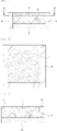
- FIG. 1 shows the configuration in which the insulation layer 4 is formed on the edge portion of each of the cathode layer 1, the electrolyte layer 3 and the anode layer 2 according to an exemplary embodiment of the present disclosure.
- the cathode layer 1, the electrolyte layer 3 and the anode layer 2 are formed so as to have the same width and area, and the insulation layer 4 of the edge portion is formed on the edge portion in the external direction of each of the cathode layer 1, the electrolyte layer 3 and the anode layer 2, which is clearly depicted in the cross-sectional view of A-A' of FIG. 2 .
- FIG. 1 shows the configuration in which the insulation layer 4 is formed on the edge portion of each of the cathode layer 1, the electrolyte layer 3 and the anode layer 2 according to an exemplary embodiment of the present disclosure.
- the cathode layer 1, the electrolyte layer 3 and the anode layer 2 are formed so as to have the same width and area, and the insulation layer 4 of the edge portion
- the insulation layer 4 may be formed over the entire region of the edge portion along the outer rim of the stacking structure.
- FIG. 2 illustrates the rectangular battery structure, and the shape of the edge portion may vary depending on the shape of the battery.
- the area of the layer means a top surface area of the layer in a laminating direction.
- the cathode layer 1 is formed so as to have a small width and area compared to the anode layer 2 and the electrolyte layer 3, and the insulation layer 4 is formed on an edge portion of the cathode layer 1.
- the coating of the insulation layer 4 offsets the insufficient area of the cathode layer 1, and thus respective areas of the stacked layers may be made uniform as a whole, as shown in FIG. 3 .
- the anode layer 2 may be formed so as to have a small width and area compared to the cathode layer 1 and the electrolyte layer 3, and the insulation layer 4 may be formed on an edge portion of the anode layer 2.
- the all-solid electrolyte layer 3 is formed so as to have a small width and area compared to the anode layer 2 and the cathode layer 1, and the insulation layer 4 may be formed on an edge portion of the all-solid electrolyte layer 3.
- the anode layer 2 or the cathode layer 1 may have a large area compared to the remaining layers, and the insulation layer 4 may be formed on an edge portion of each of the remaining layers, which have a smaller area.
- FIG. 5 shows the configuration according to yet another embodiment of the present disclosure, in which the cathode layer 1 and the all-solid electrolyte layer 3 have a small width and area compared to the anode layer 2, and the insulation layer 4 is formed on an edge portion of each of the cathode layer 1 and the all-solid electrolyte layer 3.
- the insulation layer 4 is formed on an edge portion of each of the cathode layer 1 and the all-solid electrolyte layer 3.
- the anode layer 2 and the all-solid electrolyte layer 3 may have a small width and area compared to the cathode layer 1, and the insulation layer 4 may be formed on an edge portion of each of the anode layer 2 and the all-solid electrolyte layer 3.
- FIGS. 3 to 5 are different from the embodiment of FIG. 1 only in terms of the position of the insulation layer 4, and the overall manufacturing process thereof may be performed in the same manner.
- a baroplastic polymer which is a block copolymer (PPMA/PS) of polypentyl methacrylate (PPMA) and polystyrene (PS), was prepared using sodium dodecyl sulfate (SDS) as a surfactant, 2,2'-azobis(2-methylpropionamidine) dihydrochloride (V50) as an initiator, and pentyl methacrylate (PMA) and styrene as monomers.
- SDS sodium dodecyl sulfate
- V50 2,2'-azobis(2-methylpropionamidine) dihydrochloride
- PMA pentyl methacrylate
- xylene was used as a solvent.
- the weight ratio of PMA and styrene monomers was 1:1.
- the finally synthesized product was a 40 wt% polymer emulsion.
- a cathode slurry was prepared using 83 wt% of Li(Ni 0.7 Co 0.1 Mn 0.1 )O 2 as a cathode active material, 3 wt% of carbon black and 1 wt% of graphite-based SFG6L (made by Timcal) as conductive additives, 3 wt% of nitrile-butadiene rubber (NBR) as a binder, 10% of 20 LiI ⁇ 80(0.75 Li 2 S ⁇ 0.25P 2 S 5 ) as a sulfide solid electrolyte, and a xylene solvent.
- the cathode slurry was applied to a thickness of 100 ⁇ m on a piece of aluminum foil having a thickness of 15 ⁇ m and then dried in an oven at 120 °C for 30 min, thus manufacturing a cathode.
- the PPMA/PS baroplastic polymer emulsion was applied to a thickness of 180 ⁇ m on the edge portion of the cathode manufactured above, and was then dried in an oven at 80°C for 4 hr, thus manufacturing a cathode-baroplastic polymer composite electrode.
- An anode slurry was prepared using 84 wt% of natural graphite as an anode active material, 3 wt% of graphite-based SFG6L (made by Timcal) as a conductive additive, 3 wt% of NBR as a binder, 10% of 20 LiI ⁇ 80(0.75 Li 2 S ⁇ 0.25P 2 S 5 ) as a sulfide solid electrolyte, and a xylene solvent.
- the anode slurry was applied to a thickness of 100 ⁇ m on a piece of copper foil having a thickness of 12 ⁇ m.
- a slurry was prepared using 20 LiI ⁇ 80(0.75 Li 2 S ⁇ 0.25P 2 S 5 ) as a sulfide solid electrolyte and a xylene solvent and then applied to a thickness of 200 ⁇ m on the coated anode plate.
- the resulting anode/solid electrolyte composite was dried in an oven at 80°C for 6 hr.
- the cathode and the anode/solid electrolyte composite were disposed to face each other and then compressed at 80 kgf or more using a roll press.
- a pouch cell was fabricated using the stacking structure thus obtained, and was then subjected to cold isostatic pressing at a pressure of 3.5 ton.
- a battery for evaluation was manufactured in the same manner as in Example 1, with the exception that a mixed slurry comprising 90 wt% of a baroplastic polymer and 10 wt% of a cathode slurry was applied on the edge portion of the cathode.
- a battery for evaluation was manufactured in the same manner as in Example 1, with the exception that a baroplastic polymer was not used.
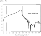
- FIGS. 6A, 6B , and 7 show the results of charge-discharge measurement of the batteries of Examples 1 and 2 and Comparative Example 1.
- the measurement was performed under conditions of room temperature, potential ranging from 2.75 V to 4.2 V, a current density of 0.1 mA/cm 2 , and constant-current charge/discharge.
- Example 2 As shown in FIG. 7 , a short circuit was confirmed in Comparative Example 1, and thus charging was not terminated. As shown in FIG. 6A , in Example 1, although it was confirmed that some leakage current was generated at the end of charging, charging and discharging were possible. As shown in FIG. 6B , in Example 2, one normal charge-discharge cycle was possible.
Landscapes
- Chemical & Material Sciences (AREA)
- Chemical Kinetics & Catalysis (AREA)
- Electrochemistry (AREA)
- General Chemical & Material Sciences (AREA)
- Engineering & Computer Science (AREA)
- Manufacturing & Machinery (AREA)
- Inorganic Chemistry (AREA)
- Materials Engineering (AREA)
- Physics & Mathematics (AREA)
- Condensed Matter Physics & Semiconductors (AREA)
- General Physics & Mathematics (AREA)
- Secondary Cells (AREA)
Description
- The present disclosure relates to an all-solid battery and a method of manufacturing the same.
- With the development and proliferation of vehicles using electrical energy, interest in safety-enhanced secondary batteries has been increasing. Since commercialized lithium ion secondary batteries use liquid electrolytes, which are volatile and heat-sensitive, the energy density of lithium ion secondary batteries gradually increases, but lithium ion secondary batteries always entail the risk of ignition and explosion. Hence, an all-solid battery having low explosion risk and high thermal stability has been receiving attention.
- However, in manufacturing an all-solid battery, a pressing process must be applied in order to improve the contact between an all-solid electrolyte and an electrode. As such, an edge portion of the electrode is stripped during the high-pressure pressing process, which causes a short circuit of the battery. Accordingly, it is required to manufacture an all-solid battery, the insulation performance of the edge portion of which is ensured.
- Techniques for ensuring insulation performance of an edge portion of an all-solid battery have been studied, in which an insulator is inserted into an electrode edge portion. However, such techniques cannot fundamentally solve the problem of short-circuiting of the edge portion because the edge portion is stripped and thus the insulator itself may break when the battery is subjected to pressure during the battery fabrication process.
- Additionally, use of a pouch with tape has been proposed, whereby an electrode edge portion is attached to a tape to thus prevent a short-circuit fault from occurring, but the likelihood of a short-circuit fault remains high owing to the spacing between the pouch and the edge portion.
-
US 2014/0079992 A1 describes a bipolar electrode comprising a current collector, a cathode active material layer formed on a first surface of the current collector and an anode active material layer formed on a second surface of the current collector opposite to its first surface. The current collector has a larger surface area than the cathode active material layer and the anode active material layer. An edge portion of the current collector is covered by a reinforcing layer made from polyester, polypropylene, polystyrene, polyamide, polyvinyl chloride or polycarbonate. - Moreover,
US 2017/0207482 A1 describes a method for manufacturing an all-solid-state battery. - The present disclosure has been made keeping in mind the problems encountered in the related art, and the present disclosure is intended to provide an all-solid battery and a method of manufacturing the same, in which an edge portion of the all-solid battery may be more effectively insulated.
- The present invention provides a method of manufacturing an all-solid battery with the features of
claim 1 and an all-solid battery with the features of claim 11. - Moreover, the baroplastic polymer may be contained in an amount of 50 volume% or more.
- The baroplastic polymer may exhibit baroplasticity at 50 °C or less and may have an average particle size of 10 - 100 µm.
- The baroplastic polymer may include a mixture of at least two selected from the group consisting of polystyrene (PS), polyisoprene (PI), poly(n-butyl acrylate) (PBA), poly(2-ethylhexyl acrylate) (PEHA), poly(pentyl methacrylate) (PPMA), poly(butyl methacrylate) (PBMA), polycarbonate (PC), poly(methyl methacrylate) (PMMA), poly(vinyl chloride) (PVC), poly(ethyl acrylate) (PEA), poly(ethyl methacrylate) (PEMA), and polybutadiene (PB).
- The step of forming the insulation layer may include sealing the battery, in which the edge portion is coated with the baroplastic polymer, in a pouch and pressing the sealed pouch at 3 ton/m2 to 5 to thus form the insulation layer.
- The cathode layer, the electrolyte layer and the anode layer may have the same area as each other, and the insulation layer of the edge portion may be formed on an edge portion in the external direction of each of the cathode layer, the electrolyte layer and the anode layer.
- The cathode layer may have a small area compared to the anode layer and the electrolyte layer, and the insulation layer of the edge portion may be formed on an edge portion of the cathode layer.
- The anode layer may have a small area compared to the cathode layer and the electrolyte layer, and the insulation layer of the edge portion may be formed on an edge portion of the anode layer.
- The electrolyte layer may have a small area compared to the anode layer and the cathode layer, and the insulation layer of the edge portion may be formed on an edge portion of the electrolyte layer.
- The anode layer or the cathode layer may have a large area compared to the remaining layers, and the insulation layer of the edge portion may be formed on an edge portion of each of the remaining layers, which have a smaller area.
- According to the present disclosure, a short circuit of an edge portion of a battery can be fundamentally prevented from occurring as a result of breaking or stripping of electrodes, etc. by pressure during a pressing process at the time of battery fabrication.
- In particular, according to the present disclosure, during isostatic pressing of the battery, an insulation layer of the edge portion can be formed using a baroplastic polymer, and thus, even when some of the electrodes are stripped in the pressing process, the baroplastic polymer is shaped in the state of being mixed with such stripped materials, thereby effectively preventing stripping of the electrode edge portion and thus short-circuiting of the battery during the pressing process.
-
-
FIG. 1 schematically shows the configuration of an all-solid battery according to an exemplary embodiment of the present disclosure; -
FIG. 2 is a cross-sectional view taken along the line A-A' in the all-solid battery ofFIG. 1 ; -
FIG. 3 is a cross-sectional view showing an all-solid battery according to another exemplary embodiment of the present disclosure; -
FIG. 4 is a cross-sectional view showing an all-solid battery according to still another exemplary embodiment of the present disclosure; -
FIG. 5 is a cross-sectional view showing an all-solid battery according to yet another exemplary embodiment of the present disclosure; and -
FIGS. 6A, 6B , and7 show the results of charge-discharge measurement of batteries of Examples 1 and 2 and Comparative Example 1. - Hereinafter, a detailed description will be given of exemplary embodiments of the present disclosure with reference to the appended drawings.
- As shown in
FIG. 1 , an all-solid battery according to the present disclosure having a stacking structure in which an electrolyte layer is interposed between acathode layer 1 and ananode layer 2, an edge portion of the battery has aninsulation layer 4 using a baroplastic polymer material. Specifically, the method of manufacturing the all-solid battery according to the present disclosure includes forming acathode layer 1 and ananode layer 2, forming anelectrolyte layer 3 between thecathode layer 1 and theanode layer 2, coating the edge portion with a baroplastic polymer material, and placing the stacking battery structure in a pouch and performing vacuum sealing and pressing, thereby manufacturing an all-solid battery in which the edge portion is insulated. - Forming the
cathode layer 1 or theanode layer 2 may be performed in a manner in which a current collector made of a metal, serving as a substrate, is coated with an anode composite slurry or a cathode composite slurry. The anode composite slurry contains an anode active material, which is typically used in the field of secondary batteries, such as silicon (Si), tin (Sn), or graphite. The cathode composite slurry contains a cathode active material, examples of the cathode active material including lithium nickel cobalt manganese (NCM) -based, lithium cobalt oxide (LCO)-based, lithium nickel cobalt aluminum (NCA)-based, and lithium iron phosphate (LFP)-based materials, which are typically used in the field of secondary batteries. - The anode composite and the cathode composite respectively contain an anode active material and a cathode active material in combination with a conductive additive and a binder, and each of the anode composite and the cathode composite may be applied in the form of a slurry. Here, the coating process may be performed using a process that is typically used in electrode coating, such as bar coating, gravure coating, or the like.
- An
electrolyte layer 3 is interposed between thecathode layer 1 and theanode layer 2, which are manufactured as above, and theelectrolyte layer 3 may be formed by subjecting an all-solid electrolyte comprising a sulfide or oxide material having ionic conductivity of 10-3 s/cm or more to insertion through lamination or coating. - The edge portion of the battery comprising the
cathode layer 1, theelectrolyte layer 3, and theanode layer 2, which are stacked, is coated with a baroplastic polymer material. - In the present disclosure, the baroplastic polymer material may be a mixture in which the term for compressibility is negative in a compressible regular solution model.
- The baroplastic polymer may have compatibility at 50 °C or less, and a baroplastic polymer powder has an average particle size of 10 to 100 µm.
- The baroplastic polymer may be a mixture comprising at least two selected from among polystyrene (PS), polyisoprene (PI), poly(n-butyl acrylate) (PBA), poly(2-ethylhexyl acrylate) (PEHA), poly(pentyl methacrylate) (PPMA), poly(butyl methacrylate) (PBMA), polycarbonate (PC), poly(methyl methacrylate) (PMMA), poly(vinyl chloride) (PVC), poly(ethyl acrylate) (PEA), poly(ethyl methacrylate) (PEMA), and polybutadiene (PB), but is not limited thereto, so long as it is baroplastic under predetermined pressure.
- In an exemplary embodiment of the present disclosure, the baroplastic polymer material is used to form the
insulation layer 4 at the edge portion of the battery configured such that thecathode layer 1, theanode layer 2, and theelectrolyte layer 3 are stacked. To this end, the baroplastic polymer material has to be positioned at the edge portion of the battery, and the baroplastic polymer material positioned at the edge portion is compressed under predetermined pressure, thus forming theinsulation layer 4. - In an exemplary embodiment of the present disclosure, cold isostatic pressing is applied upon the fabrication of an all-solid battery. Thus, forming the
insulation layer 4 by compressing the baroplastic polymer material may be carried out through cold isostatic pressing. In cold isostatic pressing, pressure is uniformly applied in all directions using a liquid at a low temperature. - For example, a pouch cell in which the stacked cell is placed in a pouch is positioned in a liquid-containing vessel, and pressure is uniformly applied to the pouch cell in all directions. Here, the term "cold" indicates a low-temperature condition, and indicates the temperature of the liquid contained in the vessel. Taking into consideration the typical pressure conditions in the cold isostatic pressing process, the baroplastic polymer may be a material having baroplasticity at 3 to 5 ton/m2.
- The baroplastic polymer may be used in the form of a binder-baroplastic polymer solution, and the binder may be aqueous or nonaqueous.
- Specifically, for cold isostatic pressing, the stacking battery structure is sealed in the pouch, after which the pouch is positioned in the liquid-containing vessel and cold isostatic pressing is performed. Here, the battery structure is subjected to uniform pressure in all directions in the vessel, and the electrode edge portion may be damaged by the applied pressure. According to the present disclosure, the edge portion is coated with the baroplastic polymer material, and thus the baroplastic polymer is shaped while being subjected to pressure.
- In particular, according to the present disclosure, since the baroplastic polymer is shaped during the pressing process, even when the cathode layer, the anode layer, or the all-
solid electrolyte layer 3 may break upon pressing, the baroplastic polymer is shaped together with the broken materials to thus form theinsulation layer 4. - Thus, according to the present disclosure, even when the cathode, the anode, the all-solid electrolyte, etc. are broken by pressure, space between the broken materials is filled with the baroplastic polymer. Hence, even when the edge portion of the battery breaks due to the pressing process at high pressure, a short circuit of the battery may be prevented from occurring.
- The baroplastic polymer may be used alone, or may be used in the form of a composite in combination with a cathode composite or an anode composite, in order to coat the edge portion of the battery, during the fabrication of the stacking structure configured such that the cathode layer, the anode layer and the electrolyte are stacked. Furthermore, coating may be performed by further mixing the all-solid electrolyte, or using a composite comprising the baroplastic polymer and the all-solid electrolyte, which are mixed.
- For example, in an exemplary embodiment of the present disclosure, the baroplastic polymer alone is applied on the edge portion of the battery, and is compressed under predetermined pressure, thus forming the
insulation layer 4. - In a further embodiment of the present disclosure, a composite in which a baroplastic polymer and a cathode material or an anode material are mixed together may be applied on the edge portion of the battery, followed by cold isostatic pressing, thus forming an
insulation layer 4. In still a further embodiment of the present disclosure, a composite in which at least two of a baroplastic polymer, a cathode material, an anode material and an all-solid electrolyte are mixed may be applied on the edge portion of the battery, thereby forming aninsulation layer 4. In this case, in order to effectively insulate the edge portion, the baroplastic polymer material may be used in an amount of 50 volume% or more. - The coating of the edge portion of the battery for the
insulation layer 4 including the baroplastic polymer material may be performed after coating and drying of the cathode layer, the anode layer and the all-solid electrolyte layer 3, but the present disclosure is not limited thereto. For example, the cathode layer, the anode layer and the all-solid electrolyte layer 3 are stacked, after which the coating with the baroplastic polymer material may be performed before the drying process, or the coating of the edge portion may be performed at the time of stacking of the all-solid battery. - According to the present disclosure, the position of the edge portion on which the
insulation layer 4 is formed may be variously set. -
FIG. 1 shows the configuration in which theinsulation layer 4 is formed on the edge portion of each of thecathode layer 1, theelectrolyte layer 3 and theanode layer 2 according to an exemplary embodiment of the present disclosure. As shown inFIG. 1 , thecathode layer 1, theelectrolyte layer 3 and theanode layer 2 are formed so as to have the same width and area, and theinsulation layer 4 of the edge portion is formed on the edge portion in the external direction of each of thecathode layer 1, theelectrolyte layer 3 and theanode layer 2, which is clearly depicted in the cross-sectional view of A-A' ofFIG. 2 . As shown inFIG. 2 , theinsulation layer 4 may be formed over the entire region of the edge portion along the outer rim of the stacking structure.FIG. 2 illustrates the rectangular battery structure, and the shape of the edge portion may vary depending on the shape of the battery. In the present disclosure, the area of the layer means a top surface area of the layer in a laminating direction. - As illustrated in
FIG. 3 , according to another embodiment of the present disclosure, thecathode layer 1 is formed so as to have a small width and area compared to theanode layer 2 and theelectrolyte layer 3, and theinsulation layer 4 is formed on an edge portion of thecathode layer 1. In this case, the coating of theinsulation layer 4 offsets the insufficient area of thecathode layer 1, and thus respective areas of the stacked layers may be made uniform as a whole, as shown inFIG. 3 . - Although not shown, unlike
FIG. 3 , theanode layer 2 may be formed so as to have a small width and area compared to thecathode layer 1 and theelectrolyte layer 3, and theinsulation layer 4 may be formed on an edge portion of theanode layer 2. - As illustrated in
FIG. 4 according to still another embodiment of the present disclosure, the all-solid electrolyte layer 3 is formed so as to have a small width and area compared to theanode layer 2 and thecathode layer 1, and theinsulation layer 4 may be formed on an edge portion of the all-solid electrolyte layer 3. - In yet another embodiment of the present disclosure, the
anode layer 2 or thecathode layer 1 may have a large area compared to the remaining layers, and theinsulation layer 4 may be formed on an edge portion of each of the remaining layers, which have a smaller area. For example,FIG. 5 shows the configuration according to yet another embodiment of the present disclosure, in which thecathode layer 1 and the all-solid electrolyte layer 3 have a small width and area compared to theanode layer 2, and theinsulation layer 4 is formed on an edge portion of each of thecathode layer 1 and the all-solid electrolyte layer 3. On the other hand, unlikeFIG. 5 , theanode layer 2 and the all-solid electrolyte layer 3 may have a small width and area compared to thecathode layer 1, and theinsulation layer 4 may be formed on an edge portion of each of theanode layer 2 and the all-solid electrolyte layer 3. - The embodiments of
FIGS. 3 to 5 are different from the embodiment ofFIG. 1 only in terms of the position of theinsulation layer 4, and the overall manufacturing process thereof may be performed in the same manner. - A baroplastic polymer, which is a block copolymer (PPMA/PS) of polypentyl methacrylate (PPMA) and polystyrene (PS), was prepared using sodium dodecyl sulfate (SDS) as a surfactant, 2,2'-azobis(2-methylpropionamidine) dihydrochloride (V50) as an initiator, and pentyl methacrylate (PMA) and styrene as monomers. Here, xylene was used as a solvent. Upon synthesis, the weight ratio of PMA and styrene monomers was 1:1. The finally synthesized product was a 40 wt% polymer emulsion.
- A cathode slurry was prepared using 83 wt% of Li(Ni0.7Co0.1Mn0.1)O2 as a cathode active material, 3 wt% of carbon black and 1 wt% of graphite-based SFG6L (made by Timcal) as conductive additives, 3 wt% of nitrile-butadiene rubber (NBR) as a binder, 10% of 20 LiI·80(0.75 Li2S·0.25P2S5) as a sulfide solid electrolyte, and a xylene solvent. The cathode slurry was applied to a thickness of 100 µm on a piece of aluminum foil having a thickness of 15 µm and then dried in an oven at 120 °C for 30 min, thus manufacturing a cathode.
- The PPMA/PS baroplastic polymer emulsion was applied to a thickness of 180 µm on the edge portion of the cathode manufactured above, and was then dried in an oven at 80°C for 4 hr, thus manufacturing a cathode-baroplastic polymer composite electrode.
- An anode slurry was prepared using 84 wt% of natural graphite as an anode active material, 3 wt% of graphite-based SFG6L (made by Timcal) as a conductive additive, 3 wt% of NBR as a binder, 10% of 20 LiI·80(0.75 Li2S·0.25P2S5) as a sulfide solid electrolyte, and a xylene solvent. The anode slurry was applied to a thickness of 100 µm on a piece of copper foil having a thickness of 12 µm. A slurry was prepared using 20 LiI·80(0.75 Li2S·0.25P2S5) as a sulfide solid electrolyte and a xylene solvent and then applied to a thickness of 200 µm on the coated anode plate. The resulting anode/solid electrolyte composite was dried in an oven at 80°C for 6 hr.
- The cathode and the anode/solid electrolyte composite were disposed to face each other and then compressed at 80 kgf or more using a roll press. Next, a pouch cell was fabricated using the stacking structure thus obtained, and was then subjected to cold isostatic pressing at a pressure of 3.5 ton.
- A battery for evaluation was manufactured in the same manner as in Example 1, with the exception that a mixed slurry comprising 90 wt% of a baroplastic polymer and 10 wt% of a cathode slurry was applied on the edge portion of the cathode.
- A battery for evaluation was manufactured in the same manner as in Example 1, with the exception that a baroplastic polymer was not used.
- The batteries for evaluation of Examples 1 and 2 and Comparative Example 1 were subjected to charge-discharge testing.
FIGS. 6A, 6B , and7 show the results of charge-discharge measurement of the batteries of Examples 1 and 2 and Comparative Example 1. - The measurement was performed under conditions of room temperature, potential ranging from 2.75 V to 4.2 V, a current density of 0.1 mA/cm2, and constant-current charge/discharge.
- As shown in
FIG. 7 , a short circuit was confirmed in Comparative Example 1, and thus charging was not terminated. As shown inFIG. 6A , in Example 1, although it was confirmed that some leakage current was generated at the end of charging, charging and discharging were possible. As shown inFIG. 6B , in Example 2, one normal charge-discharge cycle was possible. - Although the exemplary embodiments of the present disclosure have been disclosed for illustrative purposes, those skilled in the art will appreciate that various modifications, additions and substitutions are possible, without departing from the scope of the invention as disclosed in the accompanying claims. Also, many changes may be made to specific situations or materials within a range that does not depart from the essential scope of the present disclosure. Therefore, the present disclosure is not to be limited to the details of the exemplary embodiments thereof, but will include all embodiments within the scope of the appended claims.
Claims (16)
- A method of manufacturing an all-solid battery, comprising steps of:forming a cathode layer (1);forming an anode layer (2);forming an electrolyte layer (3) between the cathode layer (1) and the anode layer (2); andforming an insulation layer (4) using a baroplastic polymer at an edge portion of the battery;characterized in thatthe insulation layer (4) is manufactured by pressing of a coating layer of the baroplastic polymer disposed on the edge portion of the battery,wherein the insulation layer (4) includes at least one of a cathode material, an anode material, and an all-solid electrolyte.
- The method of claim 1, whereinthe baroplastic polymer is contained in an amount of 50 volume% or more.
- The method of claim 1, wherein the baroplastic polymer exhibits baroplasticity at 50 °C or less and has an average diameter of 10 - 100 µm.
- The method of claim 1, wherein the baroplastic polymer comprises a mixture of at least two selected from the group consisting of polystyrene (PS), polyisoprene (PI), poly(n-butyl acrylate) (PBA), poly(2-ethylhexyl acrylate) (PEHA), poly(pentyl methacrylate) (PPMA), poly (butyl methacrylate) (PBMA), polycarbonate (PC), poly (methyl methacrylate) (PMMA), poly(vinyl chloride) (PVC), poly(ethyl acrylate) (PEA), poly(ethyl methacrylate) (PEMA), and polybutadiene (PB).
- The method of claim 1, wherein the step of forming the insulation layer (4) comprises:sealing the battery, in which the edge portion is coated with the baroplastic polymer, in a pouch; andpressing the sealed pouch at 3 to 5 to manufacture the insulation layer (4).
- The method of claim 1, wherein the cathode layer (1), the electrolyte layer (3), and the anode layer (2) have the same surface area as each other, and
wherein the insulation layer (4) is disposed on an entire edge portion of each of the cathode layer (1), the electrolyte layer (3), and the anode layer (2). - The method of claim 1, wherein the cathode layer (1) has a smaller surface area than those of the anode layer (2) and the electrolyte layer (3), and
wherein the insulation layer (4) is disposed on an edge portion of the cathode layer (1). - The method of claim 1, wherein the anode layer (2) has a smaller surface area than those of the cathode layer (1) and the electrolyte layer (3), and
wherein the insulation layer (4) is disposed on an edge portion of the anode layer (2). - The method of claim 1, wherein the electrolyte layer (3) has a smaller surface area than those of the anode layer (2) and the cathode layer (1), and
wherein the insulation layer (4) is disposed on an edge portion of the electrolyte layer (3). - The method of claim 1, wherein the anode layer (2) or the cathode layer (1) has a larger surface area than those of remaining layers, and
wherein the insulation layer (4) is disposed on an edge portion of each of the remaining layers. - An all-solid battery, comprising:a cathode layer (1);an anode layer (2); andan electrolyte layer (3),wherein an insulation layer (4) includes a baroplastic polymer at an edge portion of the battery,characterized in thatthe insulation layer (4) is manufactured by pressing of a coating layer of the baroplastic polymer disposed on the edge portion of the battery,wherein the insulation layer (4) includes at least one of a cathode material, an anode material, and an all-solid electrolyte.
- The all-solid battery of claim 11, wherein the cathode layer (1), the electrolyte layer (3), and the anode layer (2) have the same surface area as each other, and
wherein the insulation layer (4) is disposed on an entire edge portion of each of the cathode layer (1), the electrolyte layer (3), and the anode layer (2). - The all-solid battery of claim 11, wherein the cathode layer (1) has a smaller surface area that those of the anode layer (2) and the electrolyte layer (3), and
wherein the insulation layer (4) is disposed on an edge portion of the cathode layer (1). - The all-solid battery of claim 11, wherein the anode layer (2) has a smaller surface area than those of the cathode layer (1) and the electrolyte layer (3), and
wherein the insulation layer (4) is disposed on an edge portion of the anode layer (2). - The all-solid battery of claim 11, wherein the electrolyte layer (3) has a smaller surface area than those of the anode layer (2) and the cathode layer (1), and
wherein the insulation layer (4) is disposed on an edge portion of the electrolyte layer (3). - The all-solid battery of claim 11, wherein the anode layer (2) or the cathode layer (1) has a larger surface area than those of remaining layers, and
wherein the insulation layer (4) is disposed on an edge portion of each of the remaining layers.
Applications Claiming Priority (1)
| Application Number | Priority Date | Filing Date | Title |
|---|---|---|---|
| KR1020170153857A KR102529492B1 (en) | 2017-11-17 | 2017-11-17 | All-solid battery and method for manufacturing the same |
Publications (2)
| Publication Number | Publication Date |
|---|---|
| EP3486973A1 EP3486973A1 (en) | 2019-05-22 |
| EP3486973B1 true EP3486973B1 (en) | 2022-12-07 |
Family
ID=63857712
Family Applications (1)
| Application Number | Title | Priority Date | Filing Date |
|---|---|---|---|
| EP18200223.8A Active EP3486973B1 (en) | 2017-11-17 | 2018-10-12 | All-solid battery and method of manufacturing the same |
Country Status (4)
| Country | Link |
|---|---|
| US (1) | US10971710B2 (en) |
| EP (1) | EP3486973B1 (en) |
| KR (1) | KR102529492B1 (en) |
| CN (1) | CN109802165B (en) |
Cited By (1)
| Publication number | Priority date | Publication date | Assignee | Title |
|---|---|---|---|---|
| US11104453B2 (en) | 2012-04-05 | 2021-08-31 | Sita Ypenburg Bv | Method and system for depositing and checking of baggage into airline flights |
Families Citing this family (18)
| Publication number | Priority date | Publication date | Assignee | Title |
|---|---|---|---|---|
| JP6673249B2 (en) * | 2017-02-14 | 2020-03-25 | トヨタ自動車株式会社 | Manufacturing method of laminated all solid state battery |
| JP7088071B2 (en) * | 2019-02-18 | 2022-06-21 | トヨタ自動車株式会社 | All solid state battery |
| KR102201338B1 (en) * | 2019-06-26 | 2021-01-12 | 한국생산기술연구원 | All solid battery unit cell, bipolar all solid battery comprising the same, and method for preparing the same |
| KR102908653B1 (en) | 2019-09-17 | 2026-01-06 | 현대자동차주식회사 | A cathode for all-solid state battery for preventing a short and A manufacturing method of the same |
| EP4051495A1 (en) * | 2019-10-31 | 2022-09-07 | 3M Innovative Properties Company | Insulating materials and methods thereof |
| FR3103969B1 (en) * | 2019-11-29 | 2024-02-16 | Accumulateurs Fixes | ELECTROCHEMICAL ELEMENT, MODULES AND BATTERIES CONTAINING THEM |
| CN111430789B (en) * | 2019-11-29 | 2022-09-20 | 蜂巢能源科技有限公司 | Method for reducing porosity of solid electrolyte layer and application thereof |
| KR102894932B1 (en) * | 2020-04-06 | 2025-12-05 | 주식회사 엘지에너지솔루션 | An all-solid type battery and a method for manufacturing the same |
| KR20210155878A (en) * | 2020-06-17 | 2021-12-24 | 현대자동차주식회사 | Cathode Material of Lithium Air Battery and Cathode Manufacturing Method Using the Same |
| US20230335874A1 (en) * | 2020-07-08 | 2023-10-19 | Lg Energy Solution, Ltd. | Method for manufacturing all-solid-state battery comprising solid electrolyte material |
| EP4167340A4 (en) * | 2020-07-08 | 2023-12-06 | LG Energy Solution, Ltd. | Method for manufacturing all-solid-state battery comprising solid electrolyte material |
| KR102821243B1 (en) * | 2020-11-04 | 2025-06-17 | 주식회사 엘지에너지솔루션 | All solid-state battery having a positive electrode with larger area than the negative electrode and a method for manufacturing the same |
| JP7463973B2 (en) * | 2021-01-07 | 2024-04-09 | トヨタ自動車株式会社 | Battery System |
| JP7578181B2 (en) * | 2021-03-12 | 2024-11-06 | 日産自動車株式会社 | All-solid-state battery |
| KR102806854B1 (en) * | 2021-03-30 | 2025-05-14 | 주식회사 엘지에너지솔루션 | All-Solid Battery Comprising Porous Current Collector and Battery Module Having the Same |
| KR102846162B1 (en) * | 2022-10-20 | 2025-08-12 | 삼성에스디아이 주식회사 | All solid battery and manufacturing method of the same |
| KR102854754B1 (en) * | 2022-10-25 | 2025-09-02 | 삼성에스디아이 주식회사 | All solid battery and manufacturing method of the same |
| CN115763824A (en) * | 2022-11-07 | 2023-03-07 | 中汽创智科技有限公司 | A kind of solid-state lithium-ion battery pole piece and its preparation method and solid-state lithium-ion battery |
Family Cites Families (34)
| Publication number | Priority date | Publication date | Assignee | Title |
|---|---|---|---|---|
| CA2011720C (en) * | 1989-03-30 | 1999-11-30 | Robert A. Austin | Battery in a vacuum sealed enveloping material and a process for making the same |
| US5360684A (en) * | 1993-10-25 | 1994-11-01 | Hydro-Quebec | Electrochemical cell for polymer electrolyte-lithium batteries (ACEP) |
| JP4233670B2 (en) * | 1999-03-01 | 2009-03-04 | パナソニック株式会社 | Method for producing non-aqueous electrolyte secondary battery |
| US6645675B1 (en) * | 1999-09-02 | 2003-11-11 | Lithium Power Technologies, Inc. | Solid polymer electrolytes |
| WO2001039293A2 (en) * | 1999-11-23 | 2001-05-31 | Moltech Corporation | Methods of preparing electrochemical cells |
| DE10151240A1 (en) * | 2001-10-17 | 2003-05-08 | Dilo Trading Ag Zug | Electrochemical element comprises a polymer cell composite made from an anode and cathode separated by a polymer electrolyte separator housed in an insulating composite body with vapor diffusion barriers |
| JP3953327B2 (en) * | 2002-01-21 | 2007-08-08 | Necトーキン株式会社 | Batteries and electric double layer capacitors |
| EP1581592A2 (en) * | 2003-01-07 | 2005-10-05 | Massachusetts Institute Of Technology | Structured baroplastic materials |
| EP1458037A1 (en) * | 2003-03-14 | 2004-09-15 | Matsushita Electric Industrial Co., Ltd. | Solid state battery |
| JP4055642B2 (en) * | 2003-05-01 | 2008-03-05 | 日産自動車株式会社 | High speed charge / discharge electrodes and batteries |
| JP4562364B2 (en) * | 2003-09-12 | 2010-10-13 | 日本曹達株式会社 | Block / graft copolymers and solid polymer electrolytes using them |
| CN102290605A (en) * | 2006-07-18 | 2011-12-21 | 西姆贝特公司 | Method and apparatus for solid-state microbattery photolithographic manufacture, singulation and passivation |
| JP5131283B2 (en) * | 2009-05-11 | 2013-01-30 | トヨタ自動車株式会社 | Solid battery manufacturing method and solid battery |
| GB2477552B (en) * | 2010-02-08 | 2016-01-27 | Qinetiq Ltd | Thin electrochemical cell |
| WO2012029625A1 (en) * | 2010-09-02 | 2012-03-08 | 日本電気株式会社 | Secondary battery |
| CN103140933B (en) * | 2010-10-07 | 2016-09-21 | 刮拉技术有限公司 | Secondary cell |
| KR20120044853A (en) * | 2010-10-28 | 2012-05-08 | 현대자동차주식회사 | Battery Pack Case Assembly for Electric Vehicle Using Plastic Composite |
| DE102011003746B4 (en) * | 2011-02-08 | 2017-12-28 | Fraunhofer-Gesellschaft zur Förderung der angewandten Forschung e.V. | Ion-conducting solid-state separator and its production and use |
| DE112011105286B4 (en) * | 2011-05-27 | 2020-06-18 | Toyota Jidosha Kabushiki Kaisha | Bipolar solid-state battery |
| US9887429B2 (en) * | 2011-12-21 | 2018-02-06 | Front Edge Technology Inc. | Laminated lithium battery |
| KR101586530B1 (en) * | 2013-03-11 | 2016-01-21 | 주식회사 엘지화학 | Cathode comprising insulating layer on cathode tab and secondary battery comprising the same |
| JP2015076272A (en) | 2013-10-09 | 2015-04-20 | トヨタ自動車株式会社 | All-solid-state battery |
| JP2015125893A (en) | 2013-12-26 | 2015-07-06 | トヨタ自動車株式会社 | Manufacturing method of all solid state battery |
| JP6666657B2 (en) * | 2015-04-30 | 2020-03-18 | 任天堂株式会社 | Display device |
| KR102044409B1 (en) * | 2015-05-14 | 2019-11-13 | 주식회사 엘지화학 | Battery pack including cartridge for secondary battery |
| GB2539297A (en) * | 2016-01-15 | 2016-12-14 | Saralon Gmbh | Thin battery and manufacturing method therefore |
| JP6319335B2 (en) * | 2016-01-18 | 2018-05-09 | トヨタ自動車株式会社 | Manufacturing method of all solid state battery |
| JP2018092772A (en) * | 2016-12-01 | 2018-06-14 | トヨタ自動車株式会社 | All-solid battery |
| KR102484888B1 (en) * | 2016-12-26 | 2023-01-04 | 현대자동차주식회사 | Seperator for secondary battery with enhanced stability, method for manufacturing the same |
| JP6673249B2 (en) * | 2017-02-14 | 2020-03-25 | トヨタ自動車株式会社 | Manufacturing method of laminated all solid state battery |
| KR102518686B1 (en) * | 2017-10-31 | 2023-04-05 | 현대자동차주식회사 | All-solid battery and method for manufacturing the same |
| EP3483957B1 (en) * | 2017-11-08 | 2026-05-06 | Samsung SDI Co., Ltd. | Compositions for forming a porous insulating layer, electrode for non-aqueous electrolyte rechargeable battery, the rechargeable battery and method for manufacturing the electrode |
| MX2020007957A (en) * | 2018-01-31 | 2021-07-02 | Tpi Composites Inc | A composite battery enclosure. |
| JP6856042B2 (en) * | 2018-03-06 | 2021-04-07 | トヨタ自動車株式会社 | All solid state battery |
-
2017
- 2017-11-17 KR KR1020170153857A patent/KR102529492B1/en active Active
-
2018
- 2018-10-11 US US16/157,910 patent/US10971710B2/en active Active
- 2018-10-12 EP EP18200223.8A patent/EP3486973B1/en active Active
- 2018-10-15 CN CN201811196761.3A patent/CN109802165B/en active Active
Cited By (2)
| Publication number | Priority date | Publication date | Assignee | Title |
|---|---|---|---|---|
| US11104453B2 (en) | 2012-04-05 | 2021-08-31 | Sita Ypenburg Bv | Method and system for depositing and checking of baggage into airline flights |
| US11655050B2 (en) | 2012-04-05 | 2023-05-23 | Sita Ypenburg Bv | Method and system for depositing and checking of baggage into airline flights |
Also Published As
| Publication number | Publication date |
|---|---|
| KR20190056666A (en) | 2019-05-27 |
| CN109802165B (en) | 2023-08-18 |
| US10971710B2 (en) | 2021-04-06 |
| EP3486973A1 (en) | 2019-05-22 |
| KR102529492B1 (en) | 2023-05-04 |
| US20190157648A1 (en) | 2019-05-23 |
| CN109802165A (en) | 2019-05-24 |
Similar Documents
| Publication | Publication Date | Title |
|---|---|---|
| US10971710B2 (en) | All-solid battery and method of manufacturing the same | |
| CN113594409B (en) | Pole piece and lithium ion battery | |
| EP3923388A1 (en) | Electrode sheets, electrochemical device and device | |
| CN106328992B (en) | A lithium ion battery and a method for preparing the same | |
| Sun et al. | (LiNi0. 5Co0. 2Mn0. 3O2+ AC)/graphite hybrid energy storage device with high specific energy and high rate capability | |
| CN1326257C (en) | Lithium battery negative pole and lithium battery comprising the negative pole | |
| EP4246701A1 (en) | Battery, electronic device, and mobile apparatus | |
| US12555795B2 (en) | Negative electrode plate, lithium secondary battery, and apparatus containing such lithium secondary battery | |
| KR101664244B1 (en) | Method forming electrode surface pattern and the electrode manufactured by the method and secondary battery including the same | |
| KR20070100957A (en) | Lithium ion secondary battery | |
| KR20110021974A (en) | Lithium-ion Secondary Battery Electrode and Lithium-ion Secondary Battery | |
| WO2022057189A1 (en) | Solid-state battery, battery module, battery pack, and related device thereof | |
| US20120007564A1 (en) | Nonaqueous electrolyte secondary battery and method for charging the same | |
| CN101262078A (en) | Rapidly chargeable lithium-ion battery and preparation method thereof | |
| EP3510655B1 (en) | Conductive polymer binder for a novel silicon/graphene anode in lithium ion batteries | |
| US10243195B2 (en) | Nonaqueous electrolyte secondary battery | |
| KR20190028848A (en) | All solid state battery and manufacturing method thereof | |
| CN107275669A (en) | Lithium secondary battery | |
| CN101714656A (en) | Lithium-ion secondary battery | |
| CN104979562A (en) | Lithium ion battery composite cathode with overdischarge energy to 0V and preparation method and application thereof | |
| WO2015132845A1 (en) | All-solid-state battery | |
| US20050271797A1 (en) | Method for manufacturing high power electrode for lithium secondary battery | |
| CN102723458B (en) | Lithium ion battery and cathode pole piece thereof | |
| TW201705590A (en) | Lithium battery and copolymer for its positive electrode coating capable of avoiding firing caused by local overheat and maintaining operating voltage for continuously charging and discharging | |
| EP0905809A1 (en) | Gel electrolyte secondary cell |
Legal Events
| Date | Code | Title | Description |
|---|---|---|---|
| PUAI | Public reference made under article 153(3) epc to a published international application that has entered the european phase |
Free format text: ORIGINAL CODE: 0009012 |
|
| STAA | Information on the status of an ep patent application or granted ep patent |
Free format text: STATUS: THE APPLICATION HAS BEEN PUBLISHED |
|
| AK | Designated contracting states |
Kind code of ref document: A1 Designated state(s): AL AT BE BG CH CY CZ DE DK EE ES FI FR GB GR HR HU IE IS IT LI LT LU LV MC MK MT NL NO PL PT RO RS SE SI SK SM TR |
|
| AX | Request for extension of the european patent |
Extension state: BA ME |
|
| STAA | Information on the status of an ep patent application or granted ep patent |
Free format text: STATUS: REQUEST FOR EXAMINATION WAS MADE |
|
| 17P | Request for examination filed |
Effective date: 20191122 |
|
| RBV | Designated contracting states (corrected) |
Designated state(s): AL AT BE BG CH CY CZ DE DK EE ES FI FR GB GR HR HU IE IS IT LI LT LU LV MC MK MT NL NO PL PT RO RS SE SI SK SM TR |
|
| RAP3 | Party data changed (applicant data changed or rights of an application transferred) |
Owner name: HYUNDAI MOTOR COMPANY Owner name: KIA CORPORATION |
|
| GRAP | Despatch of communication of intention to grant a patent |
Free format text: ORIGINAL CODE: EPIDOSNIGR1 |
|
| STAA | Information on the status of an ep patent application or granted ep patent |
Free format text: STATUS: GRANT OF PATENT IS INTENDED |
|
| RIC1 | Information provided on ipc code assigned before grant |
Ipc: H01M 10/0565 20100101ALI20220712BHEP Ipc: H01M 10/0585 20100101ALI20220712BHEP Ipc: H01M 10/0562 20100101ALI20220712BHEP Ipc: H01M 10/04 20060101ALI20220712BHEP Ipc: H01M 4/04 20060101AFI20220712BHEP |
|
| INTG | Intention to grant announced |
Effective date: 20220804 |
|
| GRAS | Grant fee paid |
Free format text: ORIGINAL CODE: EPIDOSNIGR3 |
|
| GRAA | (expected) grant |
Free format text: ORIGINAL CODE: 0009210 |
|
| STAA | Information on the status of an ep patent application or granted ep patent |
Free format text: STATUS: THE PATENT HAS BEEN GRANTED |
|
| AK | Designated contracting states |
Kind code of ref document: B1 Designated state(s): AL AT BE BG CH CY CZ DE DK EE ES FI FR GB GR HR HU IE IS IT LI LT LU LV MC MK MT NL NO PL PT RO RS SE SI SK SM TR |
|
| REG | Reference to a national code |
Ref country code: GB Ref legal event code: FG4D |
|
| REG | Reference to a national code |
Ref country code: CH Ref legal event code: EP Ref country code: AT Ref legal event code: REF Ref document number: 1536827 Country of ref document: AT Kind code of ref document: T Effective date: 20221215 |
|
| REG | Reference to a national code |
Ref country code: DE Ref legal event code: R096 Ref document number: 602018043912 Country of ref document: DE |
|
| REG | Reference to a national code |
Ref country code: IE Ref legal event code: FG4D |
|
| REG | Reference to a national code |
Ref country code: LT Ref legal event code: MG9D |
|
| REG | Reference to a national code |
Ref country code: NL Ref legal event code: MP Effective date: 20221207 |
|
| PG25 | Lapsed in a contracting state [announced via postgrant information from national office to epo] |
Ref country code: SE Free format text: LAPSE BECAUSE OF FAILURE TO SUBMIT A TRANSLATION OF THE DESCRIPTION OR TO PAY THE FEE WITHIN THE PRESCRIBED TIME-LIMIT Effective date: 20221207 Ref country code: NO Free format text: LAPSE BECAUSE OF FAILURE TO SUBMIT A TRANSLATION OF THE DESCRIPTION OR TO PAY THE FEE WITHIN THE PRESCRIBED TIME-LIMIT Effective date: 20230307 Ref country code: LT Free format text: LAPSE BECAUSE OF FAILURE TO SUBMIT A TRANSLATION OF THE DESCRIPTION OR TO PAY THE FEE WITHIN THE PRESCRIBED TIME-LIMIT Effective date: 20221207 Ref country code: FI Free format text: LAPSE BECAUSE OF FAILURE TO SUBMIT A TRANSLATION OF THE DESCRIPTION OR TO PAY THE FEE WITHIN THE PRESCRIBED TIME-LIMIT Effective date: 20221207 Ref country code: ES Free format text: LAPSE BECAUSE OF FAILURE TO SUBMIT A TRANSLATION OF THE DESCRIPTION OR TO PAY THE FEE WITHIN THE PRESCRIBED TIME-LIMIT Effective date: 20221207 |
|
| REG | Reference to a national code |
Ref country code: AT Ref legal event code: MK05 Ref document number: 1536827 Country of ref document: AT Kind code of ref document: T Effective date: 20221207 |
|
| PG25 | Lapsed in a contracting state [announced via postgrant information from national office to epo] |
Ref country code: RS Free format text: LAPSE BECAUSE OF FAILURE TO SUBMIT A TRANSLATION OF THE DESCRIPTION OR TO PAY THE FEE WITHIN THE PRESCRIBED TIME-LIMIT Effective date: 20221207 Ref country code: PL Free format text: LAPSE BECAUSE OF FAILURE TO SUBMIT A TRANSLATION OF THE DESCRIPTION OR TO PAY THE FEE WITHIN THE PRESCRIBED TIME-LIMIT Effective date: 20221207 Ref country code: LV Free format text: LAPSE BECAUSE OF FAILURE TO SUBMIT A TRANSLATION OF THE DESCRIPTION OR TO PAY THE FEE WITHIN THE PRESCRIBED TIME-LIMIT Effective date: 20221207 Ref country code: HR Free format text: LAPSE BECAUSE OF FAILURE TO SUBMIT A TRANSLATION OF THE DESCRIPTION OR TO PAY THE FEE WITHIN THE PRESCRIBED TIME-LIMIT Effective date: 20221207 Ref country code: GR Free format text: LAPSE BECAUSE OF FAILURE TO SUBMIT A TRANSLATION OF THE DESCRIPTION OR TO PAY THE FEE WITHIN THE PRESCRIBED TIME-LIMIT Effective date: 20230308 |
|
| P01 | Opt-out of the competence of the unified patent court (upc) registered |
Effective date: 20230511 |
|
| PG25 | Lapsed in a contracting state [announced via postgrant information from national office to epo] |
Ref country code: NL Free format text: LAPSE BECAUSE OF FAILURE TO SUBMIT A TRANSLATION OF THE DESCRIPTION OR TO PAY THE FEE WITHIN THE PRESCRIBED TIME-LIMIT Effective date: 20221207 |
|
| PG25 | Lapsed in a contracting state [announced via postgrant information from national office to epo] |
Ref country code: SM Free format text: LAPSE BECAUSE OF FAILURE TO SUBMIT A TRANSLATION OF THE DESCRIPTION OR TO PAY THE FEE WITHIN THE PRESCRIBED TIME-LIMIT Effective date: 20221207 Ref country code: RO Free format text: LAPSE BECAUSE OF FAILURE TO SUBMIT A TRANSLATION OF THE DESCRIPTION OR TO PAY THE FEE WITHIN THE PRESCRIBED TIME-LIMIT Effective date: 20221207 Ref country code: PT Free format text: LAPSE BECAUSE OF FAILURE TO SUBMIT A TRANSLATION OF THE DESCRIPTION OR TO PAY THE FEE WITHIN THE PRESCRIBED TIME-LIMIT Effective date: 20230410 Ref country code: EE Free format text: LAPSE BECAUSE OF FAILURE TO SUBMIT A TRANSLATION OF THE DESCRIPTION OR TO PAY THE FEE WITHIN THE PRESCRIBED TIME-LIMIT Effective date: 20221207 Ref country code: CZ Free format text: LAPSE BECAUSE OF FAILURE TO SUBMIT A TRANSLATION OF THE DESCRIPTION OR TO PAY THE FEE WITHIN THE PRESCRIBED TIME-LIMIT Effective date: 20221207 Ref country code: AT Free format text: LAPSE BECAUSE OF FAILURE TO SUBMIT A TRANSLATION OF THE DESCRIPTION OR TO PAY THE FEE WITHIN THE PRESCRIBED TIME-LIMIT Effective date: 20221207 |
|
| PG25 | Lapsed in a contracting state [announced via postgrant information from national office to epo] |
Ref country code: SK Free format text: LAPSE BECAUSE OF FAILURE TO SUBMIT A TRANSLATION OF THE DESCRIPTION OR TO PAY THE FEE WITHIN THE PRESCRIBED TIME-LIMIT Effective date: 20221207 Ref country code: IS Free format text: LAPSE BECAUSE OF FAILURE TO SUBMIT A TRANSLATION OF THE DESCRIPTION OR TO PAY THE FEE WITHIN THE PRESCRIBED TIME-LIMIT Effective date: 20230407 Ref country code: AL Free format text: LAPSE BECAUSE OF FAILURE TO SUBMIT A TRANSLATION OF THE DESCRIPTION OR TO PAY THE FEE WITHIN THE PRESCRIBED TIME-LIMIT Effective date: 20221207 |
|
| REG | Reference to a national code |
Ref country code: DE Ref legal event code: R097 Ref document number: 602018043912 Country of ref document: DE |
|
| PLBE | No opposition filed within time limit |
Free format text: ORIGINAL CODE: 0009261 |
|
| STAA | Information on the status of an ep patent application or granted ep patent |
Free format text: STATUS: NO OPPOSITION FILED WITHIN TIME LIMIT |
|
| PG25 | Lapsed in a contracting state [announced via postgrant information from national office to epo] |
Ref country code: DK Free format text: LAPSE BECAUSE OF FAILURE TO SUBMIT A TRANSLATION OF THE DESCRIPTION OR TO PAY THE FEE WITHIN THE PRESCRIBED TIME-LIMIT Effective date: 20221207 |
|
| 26N | No opposition filed |
Effective date: 20230908 |
|
| PG25 | Lapsed in a contracting state [announced via postgrant information from national office to epo] |
Ref country code: SI Free format text: LAPSE BECAUSE OF FAILURE TO SUBMIT A TRANSLATION OF THE DESCRIPTION OR TO PAY THE FEE WITHIN THE PRESCRIBED TIME-LIMIT Effective date: 20221207 |
|
| PG25 | Lapsed in a contracting state [announced via postgrant information from national office to epo] |
Ref country code: MC Free format text: LAPSE BECAUSE OF FAILURE TO SUBMIT A TRANSLATION OF THE DESCRIPTION OR TO PAY THE FEE WITHIN THE PRESCRIBED TIME-LIMIT Effective date: 20221207 |
|
| REG | Reference to a national code |
Ref country code: CH Ref legal event code: PL |
|
| REG | Reference to a national code |
Ref country code: BE Ref legal event code: MM Effective date: 20231031 |
|
| PG25 | Lapsed in a contracting state [announced via postgrant information from national office to epo] |
Ref country code: LU Free format text: LAPSE BECAUSE OF NON-PAYMENT OF DUE FEES Effective date: 20231012 |
|
| PG25 | Lapsed in a contracting state [announced via postgrant information from national office to epo] |
Ref country code: LU Free format text: LAPSE BECAUSE OF NON-PAYMENT OF DUE FEES Effective date: 20231012 |
|
| PG25 | Lapsed in a contracting state [announced via postgrant information from national office to epo] |
Ref country code: CH Free format text: LAPSE BECAUSE OF NON-PAYMENT OF DUE FEES Effective date: 20231031 |
|
| PG25 | Lapsed in a contracting state [announced via postgrant information from national office to epo] |
Ref country code: CH Free format text: LAPSE BECAUSE OF NON-PAYMENT OF DUE FEES Effective date: 20231031 |
|
| PG25 | Lapsed in a contracting state [announced via postgrant information from national office to epo] |
Ref country code: BE Free format text: LAPSE BECAUSE OF NON-PAYMENT OF DUE FEES Effective date: 20231031 |
|
| PG25 | Lapsed in a contracting state [announced via postgrant information from national office to epo] |
Ref country code: IE Free format text: LAPSE BECAUSE OF NON-PAYMENT OF DUE FEES Effective date: 20231012 |
|
| PG25 | Lapsed in a contracting state [announced via postgrant information from national office to epo] |
Ref country code: IE Free format text: LAPSE BECAUSE OF NON-PAYMENT OF DUE FEES Effective date: 20231012 |
|
| PG25 | Lapsed in a contracting state [announced via postgrant information from national office to epo] |
Ref country code: BG Free format text: LAPSE BECAUSE OF FAILURE TO SUBMIT A TRANSLATION OF THE DESCRIPTION OR TO PAY THE FEE WITHIN THE PRESCRIBED TIME-LIMIT Effective date: 20221207 |
|
| PG25 | Lapsed in a contracting state [announced via postgrant information from national office to epo] |
Ref country code: BG Free format text: LAPSE BECAUSE OF FAILURE TO SUBMIT A TRANSLATION OF THE DESCRIPTION OR TO PAY THE FEE WITHIN THE PRESCRIBED TIME-LIMIT Effective date: 20221207 |
|
| PG25 | Lapsed in a contracting state [announced via postgrant information from national office to epo] |
Ref country code: CY Free format text: LAPSE BECAUSE OF FAILURE TO SUBMIT A TRANSLATION OF THE DESCRIPTION OR TO PAY THE FEE WITHIN THE PRESCRIBED TIME-LIMIT; INVALID AB INITIO Effective date: 20181012 |
|
| PG25 | Lapsed in a contracting state [announced via postgrant information from national office to epo] |
Ref country code: HU Free format text: LAPSE BECAUSE OF FAILURE TO SUBMIT A TRANSLATION OF THE DESCRIPTION OR TO PAY THE FEE WITHIN THE PRESCRIBED TIME-LIMIT; INVALID AB INITIO Effective date: 20181012 |
|
| PGFP | Annual fee paid to national office [announced via postgrant information from national office to epo] |
Ref country code: IT Payment date: 20250924 Year of fee payment: 8 |
|
| PGFP | Annual fee paid to national office [announced via postgrant information from national office to epo] |
Ref country code: GB Payment date: 20250922 Year of fee payment: 8 |
|
| PGFP | Annual fee paid to national office [announced via postgrant information from national office to epo] |
Ref country code: FR Payment date: 20250925 Year of fee payment: 8 |
|
| PG25 | Lapsed in a contracting state [announced via postgrant information from national office to epo] |
Ref country code: TR Free format text: LAPSE BECAUSE OF FAILURE TO SUBMIT A TRANSLATION OF THE DESCRIPTION OR TO PAY THE FEE WITHIN THE PRESCRIBED TIME-LIMIT Effective date: 20221207 |
|
| PGFP | Annual fee paid to national office [announced via postgrant information from national office to epo] |
Ref country code: DE Payment date: 20250922 Year of fee payment: 8 |