EP3486969A1 - Secondary battery - Google Patents
Secondary battery Download PDFInfo
- Publication number
- EP3486969A1 EP3486969A1 EP17827783.6A EP17827783A EP3486969A1 EP 3486969 A1 EP3486969 A1 EP 3486969A1 EP 17827783 A EP17827783 A EP 17827783A EP 3486969 A1 EP3486969 A1 EP 3486969A1
- Authority
- EP
- European Patent Office
- Prior art keywords
- side wall
- secondary battery
- case
- safety vent
- wall parts
- Prior art date
- Legal status (The legal status is an assumption and is not a legal conclusion. Google has not performed a legal analysis and makes no representation as to the accuracy of the status listed.)
- Granted
Links
Images




Classifications
-
- H—ELECTRICITY
- H01—ELECTRIC ELEMENTS
- H01M—PROCESSES OR MEANS, e.g. BATTERIES, FOR THE DIRECT CONVERSION OF CHEMICAL ENERGY INTO ELECTRICAL ENERGY
- H01M50/00—Constructional details or processes of manufacture of the non-active parts of electrochemical cells other than fuel cells, e.g. hybrid cells
- H01M50/30—Arrangements for facilitating escape of gases
- H01M50/342—Non-re-sealable arrangements
- H01M50/3425—Non-re-sealable arrangements in the form of rupturable membranes or weakened parts, e.g. pierced with the aid of a sharp member
-
- H—ELECTRICITY
- H01—ELECTRIC ELEMENTS
- H01M—PROCESSES OR MEANS, e.g. BATTERIES, FOR THE DIRECT CONVERSION OF CHEMICAL ENERGY INTO ELECTRICAL ENERGY
- H01M10/00—Secondary cells; Manufacture thereof
- H01M10/05—Accumulators with non-aqueous electrolyte
- H01M10/052—Li-accumulators
- H01M10/0525—Rocking-chair batteries, i.e. batteries with lithium insertion or intercalation in both electrodes; Lithium-ion batteries
-
- H—ELECTRICITY
- H01—ELECTRIC ELEMENTS
- H01M—PROCESSES OR MEANS, e.g. BATTERIES, FOR THE DIRECT CONVERSION OF CHEMICAL ENERGY INTO ELECTRICAL ENERGY
- H01M10/00—Secondary cells; Manufacture thereof
- H01M10/04—Construction or manufacture in general
- H01M10/045—Cells or batteries with folded plate-like electrodes
-
- H—ELECTRICITY
- H01—ELECTRIC ELEMENTS
- H01M—PROCESSES OR MEANS, e.g. BATTERIES, FOR THE DIRECT CONVERSION OF CHEMICAL ENERGY INTO ELECTRICAL ENERGY
- H01M50/00—Constructional details or processes of manufacture of the non-active parts of electrochemical cells other than fuel cells, e.g. hybrid cells
- H01M50/10—Primary casings; Jackets or wrappings
- H01M50/102—Primary casings; Jackets or wrappings characterised by their shape or physical structure
- H01M50/103—Primary casings; Jackets or wrappings characterised by their shape or physical structure prismatic or rectangular
-
- H—ELECTRICITY
- H01—ELECTRIC ELEMENTS
- H01M—PROCESSES OR MEANS, e.g. BATTERIES, FOR THE DIRECT CONVERSION OF CHEMICAL ENERGY INTO ELECTRICAL ENERGY
- H01M50/00—Constructional details or processes of manufacture of the non-active parts of electrochemical cells other than fuel cells, e.g. hybrid cells
- H01M50/30—Arrangements for facilitating escape of gases
-
- H—ELECTRICITY
- H01—ELECTRIC ELEMENTS
- H01M—PROCESSES OR MEANS, e.g. BATTERIES, FOR THE DIRECT CONVERSION OF CHEMICAL ENERGY INTO ELECTRICAL ENERGY
- H01M50/00—Constructional details or processes of manufacture of the non-active parts of electrochemical cells other than fuel cells, e.g. hybrid cells
- H01M50/50—Current conducting connections for cells or batteries
- H01M50/543—Terminals
- H01M50/547—Terminals characterised by the disposition of the terminals on the cells
- H01M50/55—Terminals characterised by the disposition of the terminals on the cells on the same side of the cell
-
- H—ELECTRICITY
- H01—ELECTRIC ELEMENTS
- H01M—PROCESSES OR MEANS, e.g. BATTERIES, FOR THE DIRECT CONVERSION OF CHEMICAL ENERGY INTO ELECTRICAL ENERGY
- H01M50/00—Constructional details or processes of manufacture of the non-active parts of electrochemical cells other than fuel cells, e.g. hybrid cells
- H01M50/50—Current conducting connections for cells or batteries
- H01M50/543—Terminals
- H01M50/552—Terminals characterised by their shape
- H01M50/553—Terminals adapted for prismatic, pouch or rectangular cells
- H01M50/557—Plate-shaped terminals
-
- H—ELECTRICITY
- H01—ELECTRIC ELEMENTS
- H01M—PROCESSES OR MEANS, e.g. BATTERIES, FOR THE DIRECT CONVERSION OF CHEMICAL ENERGY INTO ELECTRICAL ENERGY
- H01M2200/00—Safety devices for primary or secondary batteries
- H01M2200/20—Pressure-sensitive devices
-
- Y—GENERAL TAGGING OF NEW TECHNOLOGICAL DEVELOPMENTS; GENERAL TAGGING OF CROSS-SECTIONAL TECHNOLOGIES SPANNING OVER SEVERAL SECTIONS OF THE IPC; TECHNICAL SUBJECTS COVERED BY FORMER USPC CROSS-REFERENCE ART COLLECTIONS [XRACs] AND DIGESTS
- Y02—TECHNOLOGIES OR APPLICATIONS FOR MITIGATION OR ADAPTATION AGAINST CLIMATE CHANGE
- Y02E—REDUCTION OF GREENHOUSE GAS [GHG] EMISSIONS, RELATED TO ENERGY GENERATION, TRANSMISSION OR DISTRIBUTION
- Y02E60/00—Enabling technologies; Technologies with a potential or indirect contribution to GHG emissions mitigation
- Y02E60/10—Energy storage using batteries
-
- Y—GENERAL TAGGING OF NEW TECHNOLOGICAL DEVELOPMENTS; GENERAL TAGGING OF CROSS-SECTIONAL TECHNOLOGIES SPANNING OVER SEVERAL SECTIONS OF THE IPC; TECHNICAL SUBJECTS COVERED BY FORMER USPC CROSS-REFERENCE ART COLLECTIONS [XRACs] AND DIGESTS
- Y02—TECHNOLOGIES OR APPLICATIONS FOR MITIGATION OR ADAPTATION AGAINST CLIMATE CHANGE
- Y02P—CLIMATE CHANGE MITIGATION TECHNOLOGIES IN THE PRODUCTION OR PROCESSING OF GOODS
- Y02P70/00—Climate change mitigation technologies in the production process for final industrial or consumer products
- Y02P70/50—Manufacturing or production processes characterised by the final manufactured product
-
- Y—GENERAL TAGGING OF NEW TECHNOLOGICAL DEVELOPMENTS; GENERAL TAGGING OF CROSS-SECTIONAL TECHNOLOGIES SPANNING OVER SEVERAL SECTIONS OF THE IPC; TECHNICAL SUBJECTS COVERED BY FORMER USPC CROSS-REFERENCE ART COLLECTIONS [XRACs] AND DIGESTS
- Y02—TECHNOLOGIES OR APPLICATIONS FOR MITIGATION OR ADAPTATION AGAINST CLIMATE CHANGE
- Y02T—CLIMATE CHANGE MITIGATION TECHNOLOGIES RELATED TO TRANSPORTATION
- Y02T10/00—Road transport of goods or passengers
- Y02T10/60—Other road transportation technologies with climate change mitigation effect
- Y02T10/70—Energy storage systems for electromobility, e.g. batteries
Definitions
- the present invention relates to a secondary battery.
- a secondary battery may be recharged.
- a low-capacity secondary battery comprised of one single battery cell is used as the power source for various portable small-sized electronic devices, such as cellular phones, and camcorders.
- a high-capacity secondary battery in which several tens of battery cells are connected in a battery pack is widely used as the power source for motor drives, such as those in hybrid electric vehicles.
- the secondary battery is manufactured in various shapes, and representative shapes include a cylindrical shape, a prismatic shape and a pouch shape.
- the secondary battery is configured such that an electrode assembly formed by positive and negative electrode plates with a separator as an insulator interposed therebetween, and an electrolyte, are housed in a case, and a cap plate is coupled to the case.
- positive and negative electrode terminals are connected to the electrode assembly and then exposed or protruded to the outside through the cap plate.
- the present invention provides a secondary battery having a safety vent integrally formed with a side wall part of a case, whereby the secondary battery is improved in safety and has effects of reducing the manufacturing cost and simplifying the manufacturing process.
- a secondary battery comprising: an electrode assembly; a case for receiving the electrode assembly; and a cap plate for covering an opened opening of the case, wherein the case includes two pairs of side wall parts, the side wall parts in each pair facing each other, and a bottom part perpendicular to the side wall parts, and a safety vent is integrally formed with an edge part of one region selected from among the side wall parts and the bottom part.
- the safety vent may be formed by cutting a portion of the case a predetermined depth from the exterior surface of the case.
- the safety vent may include a vent groove having a predetermined depth from the exterior surface of the case and a notch groove having a predetermined depth from the bottom surface of the vent groove.
- a sum of the depth of the vent groove and the depth of the notch groove may be 70% to 90% of the overall thickness of a region where the safety vent is formed.
- the safety vent may include a rounded leading edge and a linear trailing edge formed at its one and the other sides, respectively.
- the trailing edge of the safety vent may be positioned on the same line with an edge part of the region where the safety vent is formed.
- the edge part of the region where the safety vent is formed may be a place where each of the side wall parts and the bottom part meet.
- the two pairs of side wall parts may include first and second long side wall parts spaced apart from each other and facing each other; and first and second short side wall parts spaced apart from each other and having smaller areas than the first and second long side wall parts.
- the safety vent may be formed at one selected from the first short side wall part and the second short side wall part.
- the safety vent may be formed at the bottom part of the case.
- the secondary battery since the safety vent is integrally formed with a side wall part of the case, the secondary battery may have improved safety and can demonstrate effects of reducing the manufacturing cost and simplifying the manufacturing process.
- the trailing edge of the safety vent is positioned at an edge part of an end of the side wall part, the processability and accuracy in manufacturing the secondary battery can be improved.
- first, second, etc. may be used herein to describe various members, elements, regions, layers and/or sections, these members, elements, regions, layers and/or sections should not be limited by these terms. These terms are only used to distinguish one member, element, region, layer and/or section from another. Thus, for example, a first member, a first element, a first region, a first layer and/or a first section discussed below could be termed a second member, a second element, a second region, a second layer and/or a second section without departing from the teachings of the present disclosure.
- FIG. 1 is a perspective view of a secondary battery according to an embodiment of the present invention.
- FIG. 2 is a cross-sectional view of a secondary battery according to an embodiment of the present invention.
- the secondary battery 100 includes an electrode assembly 110, a first terminal 120, a second terminal 130, a case 140 and a cap plate 150.
- the electrode assembly 110 may be formed by winding or stacking a stack structure of a first electrode plate 111, a separator 113, and a second electrode plate 112, which are formed of thin plates or layers.
- the first electrode plate 111 may serve as a negative electrode and the second electrode plate 112 may serve as a positive electrode, or vice versa.
- the first electrode plate 111 may be formed by coating a first electrode active material, such as a transition metal, on a first electrode collector plate formed of a metal foil made of aluminum or an aluminum alloy.
- the first electrode plate 111 may include a first electrode active material layer 111a where the first electrode active material is coated and a first electrode uncoated portion 111b where the first electrode active material is not coated.
- the first electrode uncoated portion 111b may function as a passage for current flowing between the first electrode plate 111 and an exterior of the first electrode plate 111. Meanwhile, the present invention does not limit the material of the first electrode plate 111 to those disclosed herein.
- the second electrode plate 112 may be formed by coating a second electrode active material, such as graphite or carbon, on a second electrode collector plate formed of a metal foil made of copper, a copper alloy, nickel or a nickel alloy.
- the second electrode plate 112 may include a second electrode active material layer (not shown) where the second electrode active material is coated and a second electrode uncoated portion 112b where the second electrode active material is not coated.
- the second electrode uncoated portion 112b may function as a passage for current flowing between the second electrode plate 112 and an exterior of the second electrode plate 112. Meanwhile, the present invention does not limit the material of the second electrode plate 112 to those disclosed herein.
- the first electrode plate 111 and the second electrode plate 112 may be disposed by changing their polarities.
- the separator 113 may be positioned between the first electrode plate 111 and the second electrode plate 112 to prevent electrical short circuits and to allow movement of lithium ions.
- the separator 113 may be made, for example, of polyethylene, polypropylene, or a composite film of polypropylene and polyethylene. Meanwhile, the present invention does not limit the material of the separator 113 to those disclosed herein.
- the electrode assembly 110 may be practically accommodated in the case 140 with an electrolytic solution.
- the electrolytic solution may include a lithium salt dissolved in an organic solvent.
- the electrolytic solution may be in a liquid, a solid or a gel phase.
- first electrode tab 111b and the second electrode tab 112b may be connected to at least each one portion of the first electrode plate 111 and the second electrode plate 112, respectively.
- first electrode tab 111b is interposed between the electrode assembly 110 and the first terminal 120
- second electrode tab 112b is interposed between the electrode assembly 110 and the second terminal 130.
- first electrode tab 111b and the second electrode tab 112b may be collectively referred to as electrode tabs 111b and 112b.
- the first electrode tab 111b may be the first electrode uncoated portion of the first electrode plate 111 of the electrode assembly 110, where the first electrode active material is not coated, or may be a separate member connected to the first electrode uncoated portion.
- the second electrode tab 112b may be the second electrode uncoated portion of the second electrode plate 112 of the electrode assembly 110, where the second electrode active material is not coated, or may be a separate member connected to the second electrode uncoated portion.
- the first electrode tab 111b is extended from a top end of the electrode assembly 110 to a bottom end of the first terminal 120, which will later be described, and the second electrode tab 112b is extended from the top end of the electrode assembly 110 to a bottom end of the second terminal 130, which will later be described.
- the first electrode tab 111b and the second electrode tab 112b are directly electrically connected or welded to the first terminal 120 and the second terminal 130, respectively.
- the plurality of electrode tabs 111b and 112b are extended from the electrode assembly 110, thereby obtaining a high output current.
- the electrode tabs 111b, 112b (i.e., uncoated portions or separate members) of the electrode assembly 110 are directly electrically connected to the terminals, electric paths can be shortened, thereby simplifying electrically connecting processes between the electrode assembly 110 and the terminals, lowering internal resistance of the secondary battery and reducing the number of components of the secondary battery.
- a winding axis of the electrode assembly 110 is substantially parallel with terminal axes of the first and second terminals 120 and 130, the electrode assembly 110 may have excellent capability of impregnating an electrolyte solution in injecting the electrolyte solution.
- the first terminal 120 is electrically connected to the first electrode plate 111 and includes a first terminal pillar 121 and a first terminal plate 122.
- the first terminal pillar 121 is upwardly protruded and extended a predetermined length while extending through a cap plate 151, which will later be described.
- the first terminal pillar 121 is electrically connected to the first electrode tab 111b from below the cap plate 151.
- the first terminal pillar 121 includes a flange 121a formed to prevent the first terminal pillar 121 from being dislodged from the cap plate 151 from below the cap plate 151.
- the first electrode tab 111b is electrically connected or welded to the flange 121a.
- the first terminal pillar 121 is electrically insulated from the cap plate 151.
- the first terminal 120 is a positive electrode terminal
- the first terminal pillar 121 may be electrically connected to the cap plate 151.
- the first terminal plate 122 includes a hole (not shown) formed at its center.
- the first terminal pillar 121 is coupled and welded to the hole. That is to say, boundary regions of the first terminal pillar 121 and the first terminal plate 122, which are upwardly exposed, are welded to each other.
- laser beams are applied to the boundary regions of the first terminal pillar 121 and the first terminal plate 122 to allow the boundary regions to be fused to each other, followed by cooling, thereby achieving welding of the first terminal pillar 121 and the first terminal plate 122.
- the second terminal 130 is electrically connected to the second electrode plate 112 and includes a second terminal pillar 131 and a second terminal plate 132.
- the second terminal pillar 131 is upwardly protruded and extended a predetermined length while extending through the cap plate 151, which will later be described.
- the second terminal pillar 131 is electrically connected to the second electrode tab 112b from below the cap plate 151.
- the second terminal pillar 131 includes a flange 131a formed to prevent the second terminal pillar 131 from being dislodged from the cap plate 151 from below the cap plate 151.
- the second electrode tab 112b is electrically connected or welded to the flange 131a.
- the second terminal pillar 131 is electrically insulated from the cap plate 151.
- the second terminal pillar 131 may be electrically connected to the cap plate 151.
- the second terminal plate 132 includes a hole (not shown).
- the second terminal pillar 131 is coupled and welded to the hole. That is to say, boundary regions of the second terminal pillar 131 and the second terminal plate 132, which are upwardly exposed, are welded to each other.
- laser beams are applied to the boundary regions of the second terminal pillar 131 and the second terminal plate 132 to allow the boundary regions to be fused to each other, followed by cooling, thereby achieving welding of the second terminal pillar 131 and the second terminal plate 132.
- the case 140 is formed in a substantially hexahedral shape and may have an opening formed at its top portion to be opened.
- the case 140 includes a receiving part 140a in which the electrode assembly 110, the first terminal 120 and the second terminal 130 are inserted and placed.
- the case 140 includes two pairs of side wall parts spaced a predetermined distance apart from each other and facing each other and a bottom part formed at bottom portions of the two pairs of side wall parts to be substantially perpendicular thereto.
- the interior surface of the case 140 may be insulated, so that the case 140 is insulated from the electrode assembly 110, the first terminal 120, the second terminal 130 and the cap assembly 150.
- the side wall parts include a pair of long side wall parts 141 and 142 having relatively large areas and a pair of short side wall parts 143 and 144 having relatively small areas.
- a safety vent 146 may be formed at one of the pair of short side wall parts 143 and 144, which will later be described in more detail.
- the case 140 may be made of a conductive metal, such as aluminum, an aluminum alloy or nickel pated steel.
- the interior surface of the case 140 may be insulated, so that the case 140 is insulated from the electrode assembly 110, the first terminal 120, the second terminal 130 and the cap assembly 150.
- the cap assembly 150 is coupled to the case 140. That is to say, the cap assembly 150 closes the opening of the case 140.
- the cap assembly 150 includes the cap plate 151, an upper insulation member 152a, a lower insulation member 152b, a seal gasket 152c, and a plug 153.
- the cap plate 151 may seal the opening of the case 140 and may be made of the same material as the case 140.
- the cap plate 151 may be coupled to the case 140 by laser welding.
- the cap plate 151 and the first terminal 120 may have the same polarity, as described above. Accordingly, the cap plate 151 and the case 140 may also have the same polarity.
- the cap plate 151 includes an electrolyte injection hole 151a, through which an electrolytic solution is injected into the case 140.
- the electrolyte injection hole 151a is sealed by the plug 153.
- the upper insulation member 152a is formed between each of the first terminal pillar 121 and the second terminal pillar 131 and the cap plate 151. In addition, the upper insulation member 152a makes close contact with the cap plate 151. In addition, the upper insulation member 152a makes close contact with the gasket 152c as well. The upper insulation member 152a electrically insulates each of the first terminal pillar 121 and the second terminal pillar 131 from the cap plate 151.
- the lower insulation member 152b is formed between each of the first electrode tab 111b and the second electrode tab 112b and the cap plate 151 to prevent unnecessary electric shorts from occurring between each of the first electrode tab 111b and the second electrode tab 112b and the cap plate 151. That is to say, the lower insulation member 152b prevents electric shorts between the first electrode tab 111b and the cap plate 151 and between the second electrode tab 112b and the cap plate 151.
- the seal gasket 152c is formed between each of the first terminal pillar 121 and the second terminal pillar 131 and the cap plate 151 using an insulating material and seals portions between each of the first terminal pillar 121 and the second terminal pillar 131 and the cap plate 151.
- the gasket 152c may prevent external moisture from penetrating into the secondary battery 100 or may prevent an electrolyte contained in the secondary battery 100 from flowing out.
- the upper insulation member 152a, the lower insulation member 152b and the gasket 152c, which are disposed between the first terminal 120 and the cap plate 151, may not be provided.
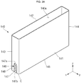
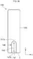
- FIGS. 3A to 3D specifically illustrate a case of the secondary battery according to an embodiment of the present invention.
- the case 140 includes an opened opening formed at its one plane, and a receiving part 140a for receiving the electrode assembly 110 is formed within the case 140.
- the case 140 includes a first long side wall part 141 and a second long side wall part 142 spaced apart from each other and facing each other, a first short side wall part 143 and a second short side wall part 144 spaced apart from each other and facing each other, and a bottom part 145 facing the opened opening.
- the safety vent 146 may be formed at the first short side wall part 143.
- the position of the safety vent 146 is not limited to that disclosed herein. Rather, the safety vent 146 may also be formed at the second short side wall part 144.
- the safety vent 146 is formed at a lower portion of the first short side wall part 143.
- an end of the safety vent 146 may coincide with an end of the first short side wall part 143.
- the safety vent 146 includes a vent groove 147 and a notch groove 148. As the result of forming the vent groove 147 and the notch groove 148, the safety vent 146 may have a smaller thickness than other regions of the first short side wall part 143.
- the vent groove 147 is formed to have a predetermined depth ranging from the exterior surface of the first short side wall part 143 to the interior surface corresponding to the receiving part 140a.
- the vent groove 147 includes a leading edge 147a and a trailing edge 147b.
- the leading edge 147a may be a region where processing of the vent groove 147 is started, and the trailing edge 147b may be a region where processing of the vent groove 147 is terminated.
- the leading edge 147a may have a rounded shape, and the trailing edge 147b may have a linear shape.
- the trailing edge 147b may be positioned at an edge part C between the first side wall part 143 and the bottom part 145 of the case 140.
- the edge part C may be positioned at a shorter one of edges of the first side wall part 143.
- the notch groove 148 is formed to have a predetermined depth ranging from a bottom surface of the vent groove 147 to the interior surface.
- a region corresponding to the notch groove 148 that is, a notch portion, is practically ruptured by high-temperature, high-pressure gases generated when the secondary battery 100 abnormally operates due to, for example, over-charge or electrical short circuit. That is to say, since the notch portion corresponding to the notch groove 148 is formed to have a smaller thickness than other regions of the safety vent 146, it is ruptured when the internal pressure of the secondary battery 100 is increased, thereby releasing the internal gases to the outside.
- a depth T2 of the vent groove 147 may be 40% to 60% of the overall thickness T1 of the first side wall part 143.
- a depth T3 of the notch groove 148 may be 40% to 60% of the depth T2 of the vent groove 147.
- a sum (T2+T3) of the depth T2 of the vent groove 147 and the depth T3 of the notch groove 148 is preferably 70% to 90% of the overall thickness T1 of the first side wall part 143. That is to say, a thickness T4 of the notch portion of the safety vent 146, corresponding to the notch groove 148, is preferably 10% to 30% of the overall thickness T1 of the first side wall part 143.
- the thickness T4 of the notch portion is less than 10%, the notch portion is easily ruptured even with a low internal pressure, which is not desirable. In addition, if the thickness T4 of the notch portion is greater than 30%, the notch portion may not be timely ruptured, which is not desirable, either.
- the vent groove 147 is formed through computer numerical control (CNC) processing using a high-speed cutting tool. That is to say, the vent groove 147 is formed by cutting a portion of the first short side wall part 143 using the cutting tool.
- the vent groove 147 may be formed by adding the high-speed cutting process to a transfer line of the case 140 in the course of manufacturing the secondary battery 100.
- the case 140 is transferred through the transfer line.
- the cutting tool approaches a predefined region of the first short side wall part 143 (i.e., a potential region of the leading edge) along a first axis (e.g., an axis perpendicular to the first short side wall part).
- a first axis e.g., an axis perpendicular to the first short side wall part.
- the process of cutting the short side wall part 143 using the cutting tool is started to perform processing of the leading edge 147a.
- the leading edge 147a may be shaped to conform to the cutting tool, for example, in a rounded shape in conformity with the round cutting tool.
- the trailing edge 147b and the edge part C may be positioned on the same line. Accordingly, the trailing edge 147b may be formed in a linear shape. Meanwhile, after the cutting performed up to the edge part C is completed, the cutting tool is separated away from the first short side wall part 143 along the first axis.
- the notch groove 148 is formed by punching the notch portion on the bottom surface of the vent groove 147.
- the forming of the notch groove 148 may be achieved by additionally performing a high-speed cutting process, like the vent groove 147.
- the secondary battery 100 according to the present invention includes the safety vent 146 having a smaller thickness than other regions of the case 140, the internal gases generated when the secondary battery 100 operates abnormally can be easily released, thereby improving the safety of the secondary battery 100.
- the safety vent 146 is positioned on the side wall part of the case 140, not on the cap plate on which a circuit module is to be installed. Therefore, the circuit module can be prevented from being damaged due to the releasing of high-temperature, high-pressure gases.
- the safety vent 146 of the secondary battery 100 is integrally formed with the case 140. That is to say, the safety vent 146 having a smaller thickness than other regions of the case 140 is formed by forming the vent groove 147 and the notch groove 148 each having a predetermined depth are formed on the first side wall part 143 of the case 140. Therefore, the secondary battery 100 according to the present invention can demonstrate effects of reducing the manufacturing cost and simplifying the manufacturing process, compared to a case where a separate safety vent is installed.
- the cutting tool simply moves along the first axis during a processing operation of the safety vent 146, the processing operation can be more easily performed.
- the cutting tool approaches the first side wall part 143 along the first axis to process the leading edge 147a.
- the cutting operation from the leading edge 147a to the edge part C can be achieved just by transferring the case 140 via the transfer line without additionally performing a separate operation.
- the cutting tool is separated from the first side wall part 143 along the first axis. That is to say, when the cutting tool approaches the case 140 or recedes from the case 140, it moves along only the first axis, instead of moving along axes of different directions. Therefore, the processing of the safety vent 146 can be simply performed, thereby improving the processability and accuracy.
- the safety vent 146 is formed to be adjacent to the end of the first side wall part 143.
- the safety vent 146 is extended from the leading edge 147a to the edge part C, the trailing edge 147b where the cutting operation is terminated is positioned on the same line with the edge part C. Therefore, the cutting tool can be made to approach the case 140 by accurately controlling only the position of the leading edge 147a, thereby improving processability and accuracy.
- the safety vent 146 is formed by cutting the first side wall part 143 up to its end portion, it is not necessary to separately control the position of the trailing edge 147b, unlike in a case where the trailing edge is positioned on another particular region of the first side wall part 143. Therefore, the approaching or receding of the cutting tool can be more easily controlled, thereby improving the processability and accuracy.
- FIG. 4 is a perspective view of a case of a secondary battery according to another embodiment of the present invention.
- the secondary battery according to another embodiment of the present invention has substantially the same configuration with the secondary battery according to the previous embodiment, except for the position of a safety vent in the case. Therefore, repeated explanation will not be given in the following description.
- the case 240 includes a first long side wall part 241 and a second long side wall part 242 spaced apart from each other and facing each other, a first short side wall part 243 and a second short side wall part 244 spaced apart from each other and facing each other, and a bottom part 245 substantially perpendicular to the side wall parts 241, 242, 243 and 244. That is to say, the bottom part 245 facing upward is illustrated in FIG. 4 , and an opened opening is formed at a region facing the bottom part 245, like in the previous embodiment.
- a safety vent 246 is formed at one end of the bottom part 245.
- the position of the safety vent 246 is not limited to that disclosed herein. Rather, the safety vent 246 may be formed at the other end of the bottom part 245.
- the safety vent 246 may coincide with an end of the bottom part 245.
- the safety vent 246 includes a vent groove 247 and a notch groove 248. As the result of forming the vent groove 247 and the notch groove 248, the safety vent 246 may have a smaller thickness than other regions of the bottom part 245.
- the vent groove 247 is formed to have a predetermined depth ranging from the exterior surface to the interior surface of the bottom part 245. Like in the previous embodiment, the vent groove 247 is formed by cutting a portion of the bottom part 245 using a cutting tool.
- the vent groove 247 includes a leading edge 247a that is a region where cutting of the vent groove 247 is started, and a trailing edge 247b that is a region where the cutting of the vent groove 247 is terminated. Therefore, the leading edge 247a may have a rounded shape, and the trailing edge 247b may have a linear shape. In particular, the trailing edge 247b may be positioned on the same line with an edge part D of the case 240 between the bottom part 245 and the first side wall part 243.
- the notch groove 248 is formed to have a predetermined depth ranging from a bottom surface of the vent groove 247 to the interior surface. That is to say, after forming the vent groove 247, the notch groove 248 is formed by punching a notch portion on the bottom surface of the vent groove 247. Alternatively, the notch groove 248 may also be formed by additionally performing a high-speed cutting process, like the vent groove 247.
- the notch groove 248 may be ruptured when the internal pressure of the secondary battery is increased, thereby releasing internal gases of the secondary battery to the outside.
- the safety vent 246 is formed on the bottom part 245, unlike in the secondary battery 100 according to the previous embodiment.
- the bottom part 245 is perpendicular to a winding axis of an electrode assembly 110, the internal gases generated in the electrode assembly 110 can be quickly moved to the safety vent 246. That is to say, the safety vent 246 can relatively quickly operate.
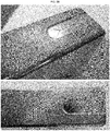
- FIGS. 5A and 5B illustrate practical application examples of a case in a secondary battery according to the present invention.
- a safety vent is formed on a bottom surface of a side wall part of the case in the secondary battery according to the present invention.
- an end of the safety vent is extended to an end of the side wall part.
- a leading edge of the safety vent has a rounded shape and a trailing edge of the safety vent has a linear shape.
- a safety vent is formed on a bottom part of the case in the secondary battery according to the present invention.
- an end of the safety vent is extended up to an end of the bottom part of the case.
- a leading edge of the safety vent has a rounded shape and a trailing edge the safety vent has a linear shape.
Landscapes
- Chemical & Material Sciences (AREA)
- Chemical Kinetics & Catalysis (AREA)
- Electrochemistry (AREA)
- General Chemical & Material Sciences (AREA)
- Engineering & Computer Science (AREA)
- Manufacturing & Machinery (AREA)
- Materials Engineering (AREA)
- Sealing Battery Cases Or Jackets (AREA)
Abstract
Description
- The present invention relates to a secondary battery.
- Unlike a primary battery that cannot be charged, a secondary battery may be recharged. A low-capacity secondary battery comprised of one single battery cell is used as the power source for various portable small-sized electronic devices, such as cellular phones, and camcorders. A high-capacity secondary battery in which several tens of battery cells are connected in a battery pack is widely used as the power source for motor drives, such as those in hybrid electric vehicles.
- The secondary battery is manufactured in various shapes, and representative shapes include a cylindrical shape, a prismatic shape and a pouch shape. The secondary battery is configured such that an electrode assembly formed by positive and negative electrode plates with a separator as an insulator interposed therebetween, and an electrolyte, are housed in a case, and a cap plate is coupled to the case. Of course, positive and negative electrode terminals are connected to the electrode assembly and then exposed or protruded to the outside through the cap plate.
- The present invention provides a secondary battery having a safety vent integrally formed with a side wall part of a case, whereby the secondary battery is improved in safety and has effects of reducing the manufacturing cost and simplifying the manufacturing process.
- In accordance with an aspect of the present invention, there is provided a secondary battery comprising: an electrode assembly; a case for receiving the electrode assembly; and a cap plate for covering an opened opening of the case, wherein the case includes two pairs of side wall parts, the side wall parts in each pair facing each other, and a bottom part perpendicular to the side wall parts, and a safety vent is integrally formed with an edge part of one region selected from among the side wall parts and the bottom part.
- Here, the safety vent may be formed by cutting a portion of the case a predetermined depth from the exterior surface of the case.
- In addition, the safety vent may include a vent groove having a predetermined depth from the exterior surface of the case and a notch groove having a predetermined depth from the bottom surface of the vent groove.
- In addition, a sum of the depth of the vent groove and the depth of the notch groove may be 70% to 90% of the overall thickness of a region where the safety vent is formed.
- In addition, the safety vent may include a rounded leading edge and a linear trailing edge formed at its one and the other sides, respectively.
- The trailing edge of the safety vent may be positioned on the same line with an edge part of the region where the safety vent is formed.
- The edge part of the region where the safety vent is formed may be a place where each of the side wall parts and the bottom part meet.
- The two pairs of side wall parts may include first and second long side wall parts spaced apart from each other and facing each other; and first and second short side wall parts spaced apart from each other and having smaller areas than the first and second long side wall parts.
- The safety vent may be formed at one selected from the first short side wall part and the second short side wall part.
- In addition, the safety vent may be formed at the bottom part of the case.
- As described above, in the secondary battery according to the present invention, since the safety vent is integrally formed with a side wall part of the case, the secondary battery may have improved safety and can demonstrate effects of reducing the manufacturing cost and simplifying the manufacturing process.
- In addition, since the trailing edge of the safety vent is positioned at an edge part of an end of the side wall part, the processability and accuracy in manufacturing the secondary battery can be improved.
-
-
FIG. 1 is a perspective view of a secondary battery according to an embodiment of the present invention. -
FIG. 2 is a cross-sectional view of a secondary battery according to an embodiment of the present invention. -
FIGS. 3A to 3D specifically illustrate a case of the secondary battery according to an embodiment of the present invention. -
FIG. 4 is a perspective view of a case in a secondary battery according to another embodiment of the present invention. -
FIGS. 5A and5B illustrate practical application examples of a case in a secondary battery according to the present invention. - Hereinafter, a preferred embodiment of the present invention will be described in detail.
- Various embodiments of the present invention may be embodied in many different forms and should not be construed as being limited to the example embodiments set forth herein. Rather, these example embodiments of the disclosure are provided so that this disclosure will be thorough and complete and will convey inventive concepts of the disclosure to those skilled in the art.
- In the accompanying drawings, sizes or thicknesses of various components are exaggerated for brevity and clarity. Like numbers refer to like elements throughout. As used herein, the term "and/or" includes any and all combinations of one or more of the associated listed items.
- The terminology used herein is for the purpose of describing particular embodiments only and is not intended to be limiting of the disclosure. As used herein, the singular forms are intended to include the plural forms as well, unless the context clearly indicates otherwise. It will be further understood that the terms "comprise" and/or "comprising," when used in this specification, specify the presence of stated features, numbers, steps, operations, elements, and/or components, but do not preclude the presence or addition of one or more other features, numbers, steps, operations, elements, components, and/or groups thereof.
- It will be understood that, although the terms first, second, etc. may be used herein to describe various members, elements, regions, layers and/or sections, these members, elements, regions, layers and/or sections should not be limited by these terms. These terms are only used to distinguish one member, element, region, layer and/or section from another. Thus, for example, a first member, a first element, a first region, a first layer and/or a first section discussed below could be termed a second member, a second element, a second region, a second layer and/or a second section without departing from the teachings of the present disclosure.
- First, a configuration of a secondary battery according to an embodiment of the present invention will be described with reference to
FIGS. 1 and2 . -
FIG. 1 is a perspective view of a secondary battery according to an embodiment of the present invention.FIG. 2 is a cross-sectional view of a secondary battery according to an embodiment of the present invention. - Referring to
FIGS. 1 and2 , thesecondary battery 100 according to an embodiment of the present invention includes anelectrode assembly 110, afirst terminal 120, asecond terminal 130, acase 140 and acap plate 150. - The
electrode assembly 110 may be formed by winding or stacking a stack structure of afirst electrode plate 111, aseparator 113, and asecond electrode plate 112, which are formed of thin plates or layers. Thefirst electrode plate 111 may serve as a negative electrode and thesecond electrode plate 112 may serve as a positive electrode, or vice versa. - The
first electrode plate 111 may be formed by coating a first electrode active material, such as a transition metal, on a first electrode collector plate formed of a metal foil made of aluminum or an aluminum alloy. Thefirst electrode plate 111 may include a first electrodeactive material layer 111a where the first electrode active material is coated and a first electrode uncoatedportion 111b where the first electrode active material is not coated. The first electrodeuncoated portion 111b may function as a passage for current flowing between thefirst electrode plate 111 and an exterior of thefirst electrode plate 111. Meanwhile, the present invention does not limit the material of thefirst electrode plate 111 to those disclosed herein. - The
second electrode plate 112 may be formed by coating a second electrode active material, such as graphite or carbon, on a second electrode collector plate formed of a metal foil made of copper, a copper alloy, nickel or a nickel alloy. Thesecond electrode plate 112 may include a second electrode active material layer (not shown) where the second electrode active material is coated and a second electrode uncoatedportion 112b where the second electrode active material is not coated. The second electrode uncoatedportion 112b may function as a passage for current flowing between thesecond electrode plate 112 and an exterior of thesecond electrode plate 112. Meanwhile, the present invention does not limit the material of thesecond electrode plate 112 to those disclosed herein. - The
first electrode plate 111 and thesecond electrode plate 112 may be disposed by changing their polarities. - The
separator 113 may be positioned between thefirst electrode plate 111 and thesecond electrode plate 112 to prevent electrical short circuits and to allow movement of lithium ions. Theseparator 113 may be made, for example, of polyethylene, polypropylene, or a composite film of polypropylene and polyethylene. Meanwhile, the present invention does not limit the material of theseparator 113 to those disclosed herein. - The
electrode assembly 110 may be practically accommodated in thecase 140 with an electrolytic solution. The electrolytic solution may include a lithium salt dissolved in an organic solvent. In addition, the electrolytic solution may be in a liquid, a solid or a gel phase. - Meanwhile, the
first electrode tab 111b and thesecond electrode tab 112b may be connected to at least each one portion of thefirst electrode plate 111 and thesecond electrode plate 112, respectively. In more detail, thefirst electrode tab 111b is interposed between theelectrode assembly 110 and thefirst terminal 120, and thesecond electrode tab 112b is interposed between theelectrode assembly 110 and thesecond terminal 130. Throughout the specification of the present invention, thefirst electrode tab 111b and thesecond electrode tab 112b may be collectively referred to aselectrode tabs - The
first electrode tab 111b may be the first electrode uncoated portion of thefirst electrode plate 111 of theelectrode assembly 110, where the first electrode active material is not coated, or may be a separate member connected to the first electrode uncoated portion. In addition, thesecond electrode tab 112b may be the second electrode uncoated portion of thesecond electrode plate 112 of theelectrode assembly 110, where the second electrode active material is not coated, or may be a separate member connected to the second electrode uncoated portion. - The
first electrode tab 111b is extended from a top end of theelectrode assembly 110 to a bottom end of thefirst terminal 120, which will later be described, and thesecond electrode tab 112b is extended from the top end of theelectrode assembly 110 to a bottom end of thesecond terminal 130, which will later be described. Thefirst electrode tab 111b and thesecond electrode tab 112b are directly electrically connected or welded to thefirst terminal 120 and thesecond terminal 130, respectively. - In case of a high-capacity, high-output battery, the plurality of
electrode tabs electrode assembly 110, thereby obtaining a high output current. In addition, since theelectrode tabs electrode assembly 110 are directly electrically connected to the terminals, electric paths can be shortened, thereby simplifying electrically connecting processes between theelectrode assembly 110 and the terminals, lowering internal resistance of the secondary battery and reducing the number of components of the secondary battery. Additionally, since a winding axis of theelectrode assembly 110 is substantially parallel with terminal axes of the first andsecond terminals electrode assembly 110 may have excellent capability of impregnating an electrolyte solution in injecting the electrolyte solution. - The
first terminal 120 is electrically connected to thefirst electrode plate 111 and includes a firstterminal pillar 121 and a firstterminal plate 122. - The first
terminal pillar 121 is upwardly protruded and extended a predetermined length while extending through acap plate 151, which will later be described. The firstterminal pillar 121 is electrically connected to thefirst electrode tab 111b from below thecap plate 151. In addition, the firstterminal pillar 121 includes aflange 121a formed to prevent the firstterminal pillar 121 from being dislodged from thecap plate 151 from below thecap plate 151. In particular, thefirst electrode tab 111b is electrically connected or welded to theflange 121a. Meanwhile, the firstterminal pillar 121 is electrically insulated from thecap plate 151. Alternatively, when thefirst terminal 120 is a positive electrode terminal, the firstterminal pillar 121 may be electrically connected to thecap plate 151. - The first
terminal plate 122 includes a hole (not shown) formed at its center. The firstterminal pillar 121 is coupled and welded to the hole. That is to say, boundary regions of the firstterminal pillar 121 and the firstterminal plate 122, which are upwardly exposed, are welded to each other. For example, laser beams are applied to the boundary regions of the firstterminal pillar 121 and the firstterminal plate 122 to allow the boundary regions to be fused to each other, followed by cooling, thereby achieving welding of the firstterminal pillar 121 and the firstterminal plate 122. - The
second terminal 130 is electrically connected to thesecond electrode plate 112 and includes a secondterminal pillar 131 and a secondterminal plate 132. - The second
terminal pillar 131 is upwardly protruded and extended a predetermined length while extending through thecap plate 151, which will later be described. The secondterminal pillar 131 is electrically connected to thesecond electrode tab 112b from below thecap plate 151. In addition, the secondterminal pillar 131 includes aflange 131a formed to prevent the secondterminal pillar 131 from being dislodged from thecap plate 151 from below thecap plate 151. In particular, thesecond electrode tab 112b is electrically connected or welded to theflange 131a. Meanwhile, the secondterminal pillar 131 is electrically insulated from thecap plate 151. Alternatively, the secondterminal pillar 131 may be electrically connected to thecap plate 151. - The second
terminal plate 132 includes a hole (not shown). The secondterminal pillar 131 is coupled and welded to the hole. That is to say, boundary regions of the secondterminal pillar 131 and the secondterminal plate 132, which are upwardly exposed, are welded to each other. For example, laser beams are applied to the boundary regions of the secondterminal pillar 131 and the secondterminal plate 132 to allow the boundary regions to be fused to each other, followed by cooling, thereby achieving welding of the secondterminal pillar 131 and the secondterminal plate 132. - The
case 140 is formed in a substantially hexahedral shape and may have an opening formed at its top portion to be opened. Thecase 140 includes a receivingpart 140a in which theelectrode assembly 110, thefirst terminal 120 and thesecond terminal 130 are inserted and placed. Thecase 140 includes two pairs of side wall parts spaced a predetermined distance apart from each other and facing each other and a bottom part formed at bottom portions of the two pairs of side wall parts to be substantially perpendicular thereto. The interior surface of thecase 140 may be insulated, so that thecase 140 is insulated from theelectrode assembly 110, thefirst terminal 120, thesecond terminal 130 and thecap assembly 150. Here, the side wall parts include a pair of longside wall parts side wall parts safety vent 146 may be formed at one of the pair of shortside wall parts - The
case 140 may be made of a conductive metal, such as aluminum, an aluminum alloy or nickel pated steel. Here, the interior surface of thecase 140 may be insulated, so that thecase 140 is insulated from theelectrode assembly 110, thefirst terminal 120, thesecond terminal 130 and thecap assembly 150. - The
cap assembly 150 is coupled to thecase 140. That is to say, thecap assembly 150 closes the opening of thecase 140. In detail, thecap assembly 150 includes thecap plate 151, anupper insulation member 152a, alower insulation member 152b, aseal gasket 152c, and aplug 153. - The
cap plate 151 may seal the opening of thecase 140 and may be made of the same material as thecase 140. For example, thecap plate 151 may be coupled to thecase 140 by laser welding. Here, thecap plate 151 and thefirst terminal 120 may have the same polarity, as described above. Accordingly, thecap plate 151 and thecase 140 may also have the same polarity. - The
cap plate 151 includes anelectrolyte injection hole 151a, through which an electrolytic solution is injected into thecase 140. Theelectrolyte injection hole 151a is sealed by theplug 153. - The
upper insulation member 152a is formed between each of the firstterminal pillar 121 and the secondterminal pillar 131 and thecap plate 151. In addition, theupper insulation member 152a makes close contact with thecap plate 151. In addition, theupper insulation member 152a makes close contact with thegasket 152c as well. Theupper insulation member 152a electrically insulates each of the firstterminal pillar 121 and the secondterminal pillar 131 from thecap plate 151. - The
lower insulation member 152b is formed between each of thefirst electrode tab 111b and thesecond electrode tab 112b and thecap plate 151 to prevent unnecessary electric shorts from occurring between each of thefirst electrode tab 111b and thesecond electrode tab 112b and thecap plate 151. That is to say, thelower insulation member 152b prevents electric shorts between thefirst electrode tab 111b and thecap plate 151 and between thesecond electrode tab 112b and thecap plate 151. - The
seal gasket 152c is formed between each of the firstterminal pillar 121 and the secondterminal pillar 131 and thecap plate 151 using an insulating material and seals portions between each of the firstterminal pillar 121 and the secondterminal pillar 131 and thecap plate 151. Thegasket 152c may prevent external moisture from penetrating into thesecondary battery 100 or may prevent an electrolyte contained in thesecondary battery 100 from flowing out. - Meanwhile, when the
cap plate 151 and thefirst terminal 120 have the same polarity, theupper insulation member 152a, thelower insulation member 152b and thegasket 152c, which are disposed between thefirst terminal 120 and thecap plate 151, may not be provided. - Hereinafter, a case of the secondary battery according to an embodiment of the present invention will be described in more detail with reference to
FIGS. 3A to 3D. FIGS. 3A to 3D specifically illustrate a case of the secondary battery according to an embodiment of the present invention. - Referring to
FIGS. 3A to 3D , thecase 140 includes an opened opening formed at its one plane, and a receivingpart 140a for receiving theelectrode assembly 110 is formed within thecase 140. In addition, thecase 140 includes a first longside wall part 141 and a second longside wall part 142 spaced apart from each other and facing each other, a first shortside wall part 143 and a second shortside wall part 144 spaced apart from each other and facing each other, and abottom part 145 facing the opened opening. In addition, thesafety vent 146 may be formed at the first shortside wall part 143. However, the position of thesafety vent 146 is not limited to that disclosed herein. Rather, thesafety vent 146 may also be formed at the second shortside wall part 144. - The
safety vent 146 is formed at a lower portion of the first shortside wall part 143. In particular, an end of thesafety vent 146 may coincide with an end of the first shortside wall part 143. Thesafety vent 146 includes avent groove 147 and anotch groove 148. As the result of forming thevent groove 147 and thenotch groove 148, thesafety vent 146 may have a smaller thickness than other regions of the first shortside wall part 143. - The
vent groove 147 is formed to have a predetermined depth ranging from the exterior surface of the first shortside wall part 143 to the interior surface corresponding to the receivingpart 140a. In addition, thevent groove 147 includes aleading edge 147a and a trailingedge 147b. Here, the leadingedge 147a may be a region where processing of thevent groove 147 is started, and the trailingedge 147b may be a region where processing of thevent groove 147 is terminated. In addition, the leadingedge 147a may have a rounded shape, and the trailingedge 147b may have a linear shape. In particular, the trailingedge 147b may be positioned at an edge part C between the firstside wall part 143 and thebottom part 145 of thecase 140. Here, the edge part C may be positioned at a shorter one of edges of the firstside wall part 143. - The
notch groove 148 is formed to have a predetermined depth ranging from a bottom surface of thevent groove 147 to the interior surface. In the firstside wall part 143, a region corresponding to thenotch groove 148, that is, a notch portion, is practically ruptured by high-temperature, high-pressure gases generated when thesecondary battery 100 abnormally operates due to, for example, over-charge or electrical short circuit. That is to say, since the notch portion corresponding to thenotch groove 148 is formed to have a smaller thickness than other regions of thesafety vent 146, it is ruptured when the internal pressure of thesecondary battery 100 is increased, thereby releasing the internal gases to the outside. - A depth T2 of the
vent groove 147 may be 40% to 60% of the overall thickness T1 of the firstside wall part 143. In addition, a depth T3 of thenotch groove 148 may be 40% to 60% of the depth T2 of thevent groove 147. Here, a sum (T2+T3) of the depth T2 of thevent groove 147 and the depth T3 of thenotch groove 148 is preferably 70% to 90% of the overall thickness T1 of the firstside wall part 143. That is to say, a thickness T4 of the notch portion of thesafety vent 146, corresponding to thenotch groove 148, is preferably 10% to 30% of the overall thickness T1 of the firstside wall part 143. If the thickness T4 of the notch portion is less than 10%, the notch portion is easily ruptured even with a low internal pressure, which is not desirable. In addition, if the thickness T4 of the notch portion is greater than 30%, the notch portion may not be timely ruptured, which is not desirable, either. - Meanwhile, the
vent groove 147 is formed through computer numerical control (CNC) processing using a high-speed cutting tool. That is to say, thevent groove 147 is formed by cutting a portion of the first shortside wall part 143 using the cutting tool. Thevent groove 147 may be formed by adding the high-speed cutting process to a transfer line of thecase 140 in the course of manufacturing thesecondary battery 100. - In detail, the
case 140 is transferred through the transfer line. Here, the cutting tool approaches a predefined region of the first short side wall part 143 (i.e., a potential region of the leading edge) along a first axis (e.g., an axis perpendicular to the first short side wall part). Accordingly, the process of cutting the shortside wall part 143 using the cutting tool is started to perform processing of theleading edge 147a. As thecase 140 is moved through the transfer line, the cutting from theleading edge 147a to the edge part C is performed and is finally completed at the trailingedge 147b. Therefore, the leadingedge 147a may be shaped to conform to the cutting tool, for example, in a rounded shape in conformity with the round cutting tool. In addition, since the cutting is performed to reach an end, i.e., the edge part C, of the first shortside wall part 143, the trailingedge 147b and the edge part C may be positioned on the same line. Accordingly, the trailingedge 147b may be formed in a linear shape. Meanwhile, after the cutting performed up to the edge part C is completed, the cutting tool is separated away from the first shortside wall part 143 along the first axis. - After forming the
vent groove 147, thenotch groove 148 is formed by punching the notch portion on the bottom surface of thevent groove 147. Alternatively, the forming of thenotch groove 148 may be achieved by additionally performing a high-speed cutting process, like thevent groove 147. - As described above, since the
secondary battery 100 according to the present invention includes thesafety vent 146 having a smaller thickness than other regions of thecase 140, the internal gases generated when thesecondary battery 100 operates abnormally can be easily released, thereby improving the safety of thesecondary battery 100. - Here, the
safety vent 146 is positioned on the side wall part of thecase 140, not on the cap plate on which a circuit module is to be installed. Therefore, the circuit module can be prevented from being damaged due to the releasing of high-temperature, high-pressure gases. - In addition, the
safety vent 146 of thesecondary battery 100 is integrally formed with thecase 140. That is to say, thesafety vent 146 having a smaller thickness than other regions of thecase 140 is formed by forming thevent groove 147 and thenotch groove 148 each having a predetermined depth are formed on the firstside wall part 143 of thecase 140. Therefore, thesecondary battery 100 according to the present invention can demonstrate effects of reducing the manufacturing cost and simplifying the manufacturing process, compared to a case where a separate safety vent is installed. - In addition, since the cutting tool simply moves along the first axis during a processing operation of the
safety vent 146, the processing operation can be more easily performed. In other words, the cutting tool approaches the firstside wall part 143 along the first axis to process theleading edge 147a. Also, the cutting operation from theleading edge 147a to the edge part C can be achieved just by transferring thecase 140 via the transfer line without additionally performing a separate operation. After the cutting operation is completed, the cutting tool is separated from the firstside wall part 143 along the first axis. That is to say, when the cutting tool approaches thecase 140 or recedes from thecase 140, it moves along only the first axis, instead of moving along axes of different directions. Therefore, the processing of thesafety vent 146 can be simply performed, thereby improving the processability and accuracy. - Additionally, the
safety vent 146 is formed to be adjacent to the end of the firstside wall part 143. In detail, since thesafety vent 146 is extended from theleading edge 147a to the edge part C, the trailingedge 147b where the cutting operation is terminated is positioned on the same line with the edge part C. Therefore, the cutting tool can be made to approach thecase 140 by accurately controlling only the position of theleading edge 147a, thereby improving processability and accuracy. In other words, since thesafety vent 146 is formed by cutting the firstside wall part 143 up to its end portion, it is not necessary to separately control the position of the trailingedge 147b, unlike in a case where the trailing edge is positioned on another particular region of the firstside wall part 143. Therefore, the approaching or receding of the cutting tool can be more easily controlled, thereby improving the processability and accuracy. - Hereinafter, a case of a secondary battery according to another embodiment of the present invention will be described with reference to
FIG. 4 . -
FIG. 4 is a perspective view of a case of a secondary battery according to another embodiment of the present invention. - The secondary battery according to another embodiment of the present invention has substantially the same configuration with the secondary battery according to the previous embodiment, except for the position of a safety vent in the case. Therefore, repeated explanation will not be given in the following description.
- Referring to
FIG. 4 , thecase 240 includes a first longside wall part 241 and a second longside wall part 242 spaced apart from each other and facing each other, a first shortside wall part 243 and a second shortside wall part 244 spaced apart from each other and facing each other, and abottom part 245 substantially perpendicular to theside wall parts bottom part 245 facing upward is illustrated inFIG. 4 , and an opened opening is formed at a region facing thebottom part 245, like in the previous embodiment. - A
safety vent 246 is formed at one end of thebottom part 245. However, the position of thesafety vent 246 is not limited to that disclosed herein. Rather, thesafety vent 246 may be formed at the other end of thebottom part 245. - An end of the
safety vent 246 may coincide with an end of thebottom part 245. Thesafety vent 246 includes avent groove 247 and anotch groove 248. As the result of forming thevent groove 247 and thenotch groove 248, thesafety vent 246 may have a smaller thickness than other regions of thebottom part 245. - The
vent groove 247 is formed to have a predetermined depth ranging from the exterior surface to the interior surface of thebottom part 245. Like in the previous embodiment, thevent groove 247 is formed by cutting a portion of thebottom part 245 using a cutting tool. - The
vent groove 247 includes aleading edge 247a that is a region where cutting of thevent groove 247 is started, and a trailingedge 247b that is a region where the cutting of thevent groove 247 is terminated. Therefore, the leadingedge 247a may have a rounded shape, and the trailingedge 247b may have a linear shape. In particular, the trailingedge 247b may be positioned on the same line with an edge part D of thecase 240 between thebottom part 245 and the firstside wall part 243. - The
notch groove 248 is formed to have a predetermined depth ranging from a bottom surface of thevent groove 247 to the interior surface. That is to say, after forming thevent groove 247, thenotch groove 248 is formed by punching a notch portion on the bottom surface of thevent groove 247. Alternatively, thenotch groove 248 may also be formed by additionally performing a high-speed cutting process, like thevent groove 247. - Since a region corresponding to the
notch groove 248 has a smaller thickness than other regions of thecase 240, thenotch groove 248 may be ruptured when the internal pressure of the secondary battery is increased, thereby releasing internal gases of the secondary battery to the outside. - As described above, in the secondary battery according to another embodiment of the present invention, the
safety vent 246 is formed on thebottom part 245, unlike in thesecondary battery 100 according to the previous embodiment. In particular, since thebottom part 245 is perpendicular to a winding axis of anelectrode assembly 110, the internal gases generated in theelectrode assembly 110 can be quickly moved to thesafety vent 246. That is to say, thesafety vent 246 can relatively quickly operate. - Hereinafter, practical application examples of a case in a secondary battery according to the present invention will be described.
-
FIGS. 5A and5B illustrate practical application examples of a case in a secondary battery according to the present invention. - Referring to
FIG. 5A , a safety vent is formed on a bottom surface of a side wall part of the case in the secondary battery according to the present invention. Here, an end of the safety vent is extended to an end of the side wall part. In addition, a leading edge of the safety vent has a rounded shape and a trailing edge of the safety vent has a linear shape. - Referring to
FIG. 5B , a safety vent is formed on a bottom part of the case in the secondary battery according to the present invention. Here, an end of the safety vent is extended up to an end of the bottom part of the case. In addition, a leading edge of the safety vent has a rounded shape and a trailing edge the safety vent has a linear shape. - Although the foregoing embodiments have been described to practice the secondary battery of the present invention, these embodiments are set forth for illustrative purposes and do not serve to limit the invention. Those skilled in the art will readily appreciate that many modifications and variations can be made, without departing from the spirit and scope of the invention as defined in the appended claims, and such modifications and variations are encompassed within the scope and spirit of the present invention.
Claims (10)
- A secondary battery comprising:an electrode assembly;a case for receiving the electrode assembly; anda cap plate for covering an opened opening of the case,wherein the case includes two pairs of side wall parts, the side wall parts in each pair facing each other, and a bottom part perpendicular to the side wall parts, and a safety vent is integrally formed with an edge part of one region selected from the side wall parts and the bottom part.
- The secondary battery of claim 1, wherein the safety vent is formed by cutting a portion of the case a predetermined depth from the exterior surface of the case.
- The secondary battery of claim 1, wherein the safety vent includes a vent groove having a predetermined depth from the exterior surface of the case and a notch groove having a predetermined depth from the bottom surface of the vent groove.
- The secondary battery of claim 3, wherein a sum of the depth of the vent groove and the depth of the notch groove is 70% to 90% of the overall thickness of a region where the safety vent is formed.
- The secondary battery of claim 1, wherein the safety vent includes a rounded leading edge and a linear trailing edge formed at its one and the other sides, respectively.
- The secondary battery of claim 5, wherein the trailing edge is positioned on the same line with an edge part of the region where the safety vent is formed.
- The secondary battery of claim 1, wherein the edge part of the region where the safety vent is formed is a place where each of the side wall parts and the bottom part meet.
- The secondary battery of claim 1, wherein the two pairs of side wall parts include first and second long side wall parts spaced apart from each other and facing each other; and first and second short side wall parts spaced apart from each other and having smaller areas than the first and second long side wall parts.
- The secondary battery of claim 8, wherein the safety vent is formed at one selected from the first short side wall part and the second short side wall part.
- The secondary battery of claim 1, wherein the safety vent is formed at the bottom part of the case.
Applications Claiming Priority (2)
| Application Number | Priority Date | Filing Date | Title |
|---|---|---|---|
| KR1020160088094A KR102629177B1 (en) | 2016-07-12 | 2016-07-12 | Secondary Battery |
| PCT/KR2017/003343 WO2018012709A1 (en) | 2016-07-12 | 2017-03-28 | Secondary battery |
Publications (3)
| Publication Number | Publication Date |
|---|---|
| EP3486969A1 true EP3486969A1 (en) | 2019-05-22 |
| EP3486969A4 EP3486969A4 (en) | 2020-01-01 |
| EP3486969B1 EP3486969B1 (en) | 2020-12-16 |
Family
ID=60952583
Family Applications (1)
| Application Number | Title | Priority Date | Filing Date |
|---|---|---|---|
| EP17827783.6A Active EP3486969B1 (en) | 2016-07-12 | 2017-03-28 | Secondary battery |
Country Status (5)
| Country | Link |
|---|---|
| US (1) | US11502327B2 (en) |
| EP (1) | EP3486969B1 (en) |
| KR (1) | KR102629177B1 (en) |
| CN (1) | CN109314202B (en) |
| WO (1) | WO2018012709A1 (en) |
Cited By (4)
| Publication number | Priority date | Publication date | Assignee | Title |
|---|---|---|---|---|
| EP4156398A4 (en) * | 2021-06-23 | 2023-08-30 | Contemporary Amperex Technology Co., Limited | BATTERY CELL AND METHOD OF MANUFACTURING AND ASSOCIATED SYSTEM, BATTERY AND ELECTRICAL DEVICE |
| EP4243163A1 (en) * | 2022-01-05 | 2023-09-13 | Samsung SDI Co., Ltd. | Secondary battery |
| RU2833006C1 (en) * | 2021-06-23 | 2025-01-13 | Кэнтемпэрэри Эмпирэкс Текнолэджи (Гонконг) Лимитед | Battery cell, its manufacturing method and manufacturing system, battery and electric device |
| EP4621967A4 (en) * | 2023-05-09 | 2026-04-01 | Contemporary Amperex Technology Co Ltd | BATTERY CELL, BATTERY AND ELECTRICAL DEVICE |
Families Citing this family (9)
| Publication number | Priority date | Publication date | Assignee | Title |
|---|---|---|---|---|
| KR102745195B1 (en) * | 2019-10-08 | 2024-12-23 | 주식회사 엘지에너지솔루션 | Case for secondary battery, secondary battery including the same and method of manufacturing the case for secondary battery |
| JP7325642B2 (en) * | 2020-07-10 | 2023-08-14 | 寧徳時代新能源科技股▲分▼有限公司 | BATTERY CASE, BATTERY CELL, BATTERY, BATTERY CASE MANUFACTURING METHOD AND APPARATUS |
| CN112968234A (en) * | 2021-01-22 | 2021-06-15 | 刘昌国 | Lithium battery shell, lithium battery positive electrode cover plate and lithium battery |
| JP7514380B2 (en) * | 2021-08-31 | 2024-07-10 | 寧徳時代新能源科技股▲分▼有限公司 | Pressure relief device, battery cell, battery and electrical device |
| US20230155208A1 (en) * | 2021-11-15 | 2023-05-18 | Beta Air, Llc | Heat-dissipating battery pack |
| CN216980798U (en) * | 2022-05-12 | 2022-07-15 | 比亚迪股份有限公司 | Explosion-proof valve, battery module, battery package and vehicle |
| KR20240149222A (en) * | 2023-04-05 | 2024-10-14 | 에스케이온 주식회사 | Vent Plate and Secondary Battery Cell including the same |
| DE102024111496A1 (en) * | 2024-04-24 | 2025-10-30 | Hoerbiger Antriebstechnik Holding Gmbh | Cell housing for a battery cell body |
| DE102024117730A1 (en) * | 2024-06-24 | 2025-12-24 | Hoerbiger Antriebstechnik Holding Gmbh | Cell housing for holding a battery cell body |
Family Cites Families (29)
| Publication number | Priority date | Publication date | Assignee | Title |
|---|---|---|---|---|
| NL8801853A (en) * | 1988-07-22 | 1990-02-16 | Philips Nv | ELECTRONIC COMPONENT, ELECTROLYTIC CAPACITOR AND METAL ENCLOSURE. |
| KR100274938B1 (en) | 1998-08-25 | 2000-12-15 | 장용균 | The safety vent of square lithium ion battery |
| US6159631A (en) * | 1998-08-27 | 2000-12-12 | Polystor Corporation | Overcharge safety vents on prismatic cells |
| JP4355865B2 (en) * | 1998-11-10 | 2009-11-04 | 株式会社ジーエス・ユアサコーポレーション | battery |
| KR100366079B1 (en) * | 1999-10-27 | 2002-12-26 | 삼성에스디아이 주식회사 | Secondary battery |
| JP3863351B2 (en) * | 2000-02-18 | 2006-12-27 | 松下電器産業株式会社 | Method for manufacturing prismatic battery and safety mechanism for prismatic battery |
| JP2001266804A (en) | 2000-03-23 | 2001-09-28 | At Battery:Kk | Sealed secondary battery |
| JP3725433B2 (en) * | 2001-02-15 | 2005-12-14 | Necトーキン栃木株式会社 | Square battery and method of manufacturing the same |
| KR100551885B1 (en) * | 2003-10-20 | 2006-02-10 | 삼성에스디아이 주식회사 | Lithium ion secondary battery |
| KR20050037689A (en) * | 2003-10-20 | 2005-04-25 | 삼성에스디아이 주식회사 | Secondary battery with vents located at optimum positions |
| KR100601508B1 (en) | 2004-09-22 | 2006-07-19 | 삼성에스디아이 주식회사 | Secondary battery with improved safety against longitudinal compression |
| US9136507B2 (en) * | 2005-03-24 | 2015-09-15 | Samsung Sdi Co., Ltd. | Can and lithium secondary battery using the same |
| KR100670432B1 (en) * | 2005-03-25 | 2007-01-16 | 삼성에스디아이 주식회사 | Lithium secondary battery |
| KR101136215B1 (en) * | 2005-09-06 | 2012-04-17 | 삼성에스디아이 주식회사 | Secondary battery |
| JP4953225B2 (en) * | 2005-10-31 | 2012-06-13 | 日立マクセルエナジー株式会社 | Sealed prismatic battery |
| KR100914115B1 (en) * | 2007-09-10 | 2009-08-27 | 삼성에스디아이 주식회사 | Secondary battery |
| KR101350664B1 (en) * | 2008-04-03 | 2014-01-10 | 주식회사 엘지화학 | Secondary battery having an improved safety |
| KR101023919B1 (en) * | 2008-06-09 | 2011-03-22 | 삼성에스디아이 주식회사 | Lithium secondary battery |
| JP4386139B1 (en) * | 2008-08-20 | 2009-12-16 | トヨタ自動車株式会社 | battery |
| CN201311941Y (en) * | 2008-09-24 | 2009-09-16 | 比亚迪股份有限公司 | Battery casing and battery including the casing |
| JP5674165B2 (en) * | 2009-09-24 | 2015-02-25 | エルジー・ケム・リミテッド | Square secondary battery with safety groove |
| KR101082305B1 (en) * | 2009-11-17 | 2011-11-09 | 삼성에스디아이 주식회사 | Case for Secondary Battery and Secondary Battery having the same |
| US20110123844A1 (en) * | 2009-11-20 | 2011-05-26 | Apple Inc. | Pressure-relief mechanism to improve safety in lithium-polymer battery cells |
| KR101101093B1 (en) * | 2009-11-26 | 2012-01-03 | 삼성에스디아이 주식회사 | Case for secondary battery and lithium secondary battery using same |
| US8920964B2 (en) * | 2010-05-03 | 2014-12-30 | Samsung Sdi Co., Ltd. | Rechargeable battery |
| US9537135B2 (en) * | 2010-07-21 | 2017-01-03 | Samsung Sdi Co., Ltd. | Terminal of rechargeable battery and method of manufacturing the same |
| JP2014086162A (en) * | 2012-10-19 | 2014-05-12 | Hitachi Maxell Ltd | Sealed battery |
| US9583741B2 (en) * | 2013-07-05 | 2017-02-28 | Samsung Sdi Co., Ltd. | Secondary battery |
| KR20130105591A (en) | 2013-09-11 | 2013-09-25 | 주식회사 엘지화학 | Secondary battery having an improved safety |
-
2016
- 2016-07-12 KR KR1020160088094A patent/KR102629177B1/en active Active
-
2017
- 2017-03-28 WO PCT/KR2017/003343 patent/WO2018012709A1/en not_active Ceased
- 2017-03-28 US US16/309,003 patent/US11502327B2/en active Active
- 2017-03-28 EP EP17827783.6A patent/EP3486969B1/en active Active
- 2017-03-28 CN CN201780038430.4A patent/CN109314202B/en active Active
Cited By (5)
| Publication number | Priority date | Publication date | Assignee | Title |
|---|---|---|---|---|
| EP4156398A4 (en) * | 2021-06-23 | 2023-08-30 | Contemporary Amperex Technology Co., Limited | BATTERY CELL AND METHOD OF MANUFACTURING AND ASSOCIATED SYSTEM, BATTERY AND ELECTRICAL DEVICE |
| RU2833006C1 (en) * | 2021-06-23 | 2025-01-13 | Кэнтемпэрэри Эмпирэкс Текнолэджи (Гонконг) Лимитед | Battery cell, its manufacturing method and manufacturing system, battery and electric device |
| US12431582B2 (en) | 2021-06-23 | 2025-09-30 | Contemporary Amperex Technology (Hong Kong) Limited | Battery cell including pressure relief structure and cover aseembly having first recessed portion, manufacturing method and manufacturing system therefor, battery and electric device |
| EP4243163A1 (en) * | 2022-01-05 | 2023-09-13 | Samsung SDI Co., Ltd. | Secondary battery |
| EP4621967A4 (en) * | 2023-05-09 | 2026-04-01 | Contemporary Amperex Technology Co Ltd | BATTERY CELL, BATTERY AND ELECTRICAL DEVICE |
Also Published As
| Publication number | Publication date |
|---|---|
| KR20180007189A (en) | 2018-01-22 |
| CN109314202B (en) | 2021-08-20 |
| US20190260069A1 (en) | 2019-08-22 |
| KR102629177B1 (en) | 2024-01-26 |
| EP3486969A4 (en) | 2020-01-01 |
| EP3486969B1 (en) | 2020-12-16 |
| WO2018012709A1 (en) | 2018-01-18 |
| US11502327B2 (en) | 2022-11-15 |
| CN109314202A (en) | 2019-02-05 |
Similar Documents
| Publication | Publication Date | Title |
|---|---|---|
| EP3486969B1 (en) | Secondary battery | |
| US10727469B2 (en) | Secondary battery | |
| EP3514858B1 (en) | Secondary battery | |
| US11031580B2 (en) | Secondary battery with embossed safety vent | |
| US11289782B2 (en) | Secondary battery | |
| US11108095B2 (en) | Secondary battery | |
| US9530999B2 (en) | Secondary battery module | |
| US11063304B2 (en) | Secondary battery having symmetric multi-tabs | |
| US10840498B2 (en) | Secondary battery | |
| US20240313307A1 (en) | Secondary battery | |
| US9818991B2 (en) | Secondary battery | |
| US10522813B2 (en) | Secondary battery | |
| US20170279157A1 (en) | Rechargeable battery | |
| KR20130139446A (en) | Secondary battery | |
| US20240136673A1 (en) | Secondary battery | |
| KR102425799B1 (en) | Secondary Battery | |
| US9583752B2 (en) | Secondary battery | |
| KR20190098494A (en) | Secondary battery | |
| KR20170021119A (en) | Rechargeable battery | |
| KR20170033543A (en) | Electrode assembly and secondary battery using for the same | |
| KR20160059779A (en) | Rechargeable battery | |
| EP4343956A1 (en) | Secondary battery | |
| KR20180008189A (en) | Rechargeable battery | |
| KR20220112034A (en) | Secondary Battery | |
| KR20210097482A (en) | The Case For Secondary Battery |
Legal Events
| Date | Code | Title | Description |
|---|---|---|---|
| STAA | Information on the status of an ep patent application or granted ep patent |
Free format text: STATUS: THE INTERNATIONAL PUBLICATION HAS BEEN MADE |
|
| PUAI | Public reference made under article 153(3) epc to a published international application that has entered the european phase |
Free format text: ORIGINAL CODE: 0009012 |
|
| STAA | Information on the status of an ep patent application or granted ep patent |
Free format text: STATUS: REQUEST FOR EXAMINATION WAS MADE |
|
| 17P | Request for examination filed |
Effective date: 20181121 |
|
| AK | Designated contracting states |
Kind code of ref document: A1 Designated state(s): AL AT BE BG CH CY CZ DE DK EE ES FI FR GB GR HR HU IE IS IT LI LT LU LV MC MK MT NL NO PL PT RO RS SE SI SK SM TR |
|
| AX | Request for extension of the european patent |
Extension state: BA ME |
|
| DAV | Request for validation of the european patent (deleted) | ||
| DAX | Request for extension of the european patent (deleted) | ||
| A4 | Supplementary search report drawn up and despatched |
Effective date: 20191128 |
|
| RIC1 | Information provided on ipc code assigned before grant |
Ipc: H01M 2/12 20060101AFI20191122BHEP Ipc: H01M 2/02 20060101ALI20191122BHEP |
|
| GRAP | Despatch of communication of intention to grant a patent |
Free format text: ORIGINAL CODE: EPIDOSNIGR1 |
|
| STAA | Information on the status of an ep patent application or granted ep patent |
Free format text: STATUS: GRANT OF PATENT IS INTENDED |
|
| RIC1 | Information provided on ipc code assigned before grant |
Ipc: H01M 2/02 20060101ALI20200720BHEP Ipc: H01M 2/12 20060101AFI20200720BHEP |
|
| INTG | Intention to grant announced |
Effective date: 20200812 |
|
| GRAS | Grant fee paid |
Free format text: ORIGINAL CODE: EPIDOSNIGR3 |
|
| GRAA | (expected) grant |
Free format text: ORIGINAL CODE: 0009210 |
|
| STAA | Information on the status of an ep patent application or granted ep patent |
Free format text: STATUS: THE PATENT HAS BEEN GRANTED |
|
| REG | Reference to a national code |
Ref country code: DE Ref legal event code: R079 Ref document number: 602017029785 Country of ref document: DE Free format text: PREVIOUS MAIN CLASS: H01M0002120000 Ipc: H01M0050300000 |
|
| AK | Designated contracting states |
Kind code of ref document: B1 Designated state(s): AL AT BE BG CH CY CZ DE DK EE ES FI FR GB GR HR HU IE IS IT LI LT LU LV MC MK MT NL NO PL PT RO RS SE SI SK SM TR |
|
| REG | Reference to a national code |
Ref country code: GB Ref legal event code: FG4D |
|
| REG | Reference to a national code |
Ref country code: DE Ref legal event code: R096 Ref document number: 602017029785 Country of ref document: DE |
|
| REG | Reference to a national code |
Ref country code: IE Ref legal event code: FG4D |
|
| REG | Reference to a national code |
Ref country code: AT Ref legal event code: REF Ref document number: 1346398 Country of ref document: AT Kind code of ref document: T Effective date: 20210115 |
|
| PG25 | Lapsed in a contracting state [announced via postgrant information from national office to epo] |
Ref country code: FI Free format text: LAPSE BECAUSE OF FAILURE TO SUBMIT A TRANSLATION OF THE DESCRIPTION OR TO PAY THE FEE WITHIN THE PRESCRIBED TIME-LIMIT Effective date: 20201216 Ref country code: RS Free format text: LAPSE BECAUSE OF FAILURE TO SUBMIT A TRANSLATION OF THE DESCRIPTION OR TO PAY THE FEE WITHIN THE PRESCRIBED TIME-LIMIT Effective date: 20201216 Ref country code: GR Free format text: LAPSE BECAUSE OF FAILURE TO SUBMIT A TRANSLATION OF THE DESCRIPTION OR TO PAY THE FEE WITHIN THE PRESCRIBED TIME-LIMIT Effective date: 20210317 Ref country code: NO Free format text: LAPSE BECAUSE OF FAILURE TO SUBMIT A TRANSLATION OF THE DESCRIPTION OR TO PAY THE FEE WITHIN THE PRESCRIBED TIME-LIMIT Effective date: 20210316 |
|
| REG | Reference to a national code |
Ref country code: AT Ref legal event code: MK05 Ref document number: 1346398 Country of ref document: AT Kind code of ref document: T Effective date: 20201216 |
|
| REG | Reference to a national code |
Ref country code: NL Ref legal event code: MP Effective date: 20201216 |
|
| PG25 | Lapsed in a contracting state [announced via postgrant information from national office to epo] |
Ref country code: BG Free format text: LAPSE BECAUSE OF FAILURE TO SUBMIT A TRANSLATION OF THE DESCRIPTION OR TO PAY THE FEE WITHIN THE PRESCRIBED TIME-LIMIT Effective date: 20210316 Ref country code: SE Free format text: LAPSE BECAUSE OF FAILURE TO SUBMIT A TRANSLATION OF THE DESCRIPTION OR TO PAY THE FEE WITHIN THE PRESCRIBED TIME-LIMIT Effective date: 20201216 Ref country code: LV Free format text: LAPSE BECAUSE OF FAILURE TO SUBMIT A TRANSLATION OF THE DESCRIPTION OR TO PAY THE FEE WITHIN THE PRESCRIBED TIME-LIMIT Effective date: 20201216 |
|
| PG25 | Lapsed in a contracting state [announced via postgrant information from national office to epo] |
Ref country code: NL Free format text: LAPSE BECAUSE OF FAILURE TO SUBMIT A TRANSLATION OF THE DESCRIPTION OR TO PAY THE FEE WITHIN THE PRESCRIBED TIME-LIMIT Effective date: 20201216 Ref country code: HR Free format text: LAPSE BECAUSE OF FAILURE TO SUBMIT A TRANSLATION OF THE DESCRIPTION OR TO PAY THE FEE WITHIN THE PRESCRIBED TIME-LIMIT Effective date: 20201216 |
|
| REG | Reference to a national code |
Ref country code: LT Ref legal event code: MG9D |
|
| PG25 | Lapsed in a contracting state [announced via postgrant information from national office to epo] |
Ref country code: SM Free format text: LAPSE BECAUSE OF FAILURE TO SUBMIT A TRANSLATION OF THE DESCRIPTION OR TO PAY THE FEE WITHIN THE PRESCRIBED TIME-LIMIT Effective date: 20201216 Ref country code: EE Free format text: LAPSE BECAUSE OF FAILURE TO SUBMIT A TRANSLATION OF THE DESCRIPTION OR TO PAY THE FEE WITHIN THE PRESCRIBED TIME-LIMIT Effective date: 20201216 Ref country code: CZ Free format text: LAPSE BECAUSE OF FAILURE TO SUBMIT A TRANSLATION OF THE DESCRIPTION OR TO PAY THE FEE WITHIN THE PRESCRIBED TIME-LIMIT Effective date: 20201216 Ref country code: LT Free format text: LAPSE BECAUSE OF FAILURE TO SUBMIT A TRANSLATION OF THE DESCRIPTION OR TO PAY THE FEE WITHIN THE PRESCRIBED TIME-LIMIT Effective date: 20201216 Ref country code: RO Free format text: LAPSE BECAUSE OF FAILURE TO SUBMIT A TRANSLATION OF THE DESCRIPTION OR TO PAY THE FEE WITHIN THE PRESCRIBED TIME-LIMIT Effective date: 20201216 Ref country code: SK Free format text: LAPSE BECAUSE OF FAILURE TO SUBMIT A TRANSLATION OF THE DESCRIPTION OR TO PAY THE FEE WITHIN THE PRESCRIBED TIME-LIMIT Effective date: 20201216 Ref country code: PT Free format text: LAPSE BECAUSE OF FAILURE TO SUBMIT A TRANSLATION OF THE DESCRIPTION OR TO PAY THE FEE WITHIN THE PRESCRIBED TIME-LIMIT Effective date: 20210416 |
|
| PG25 | Lapsed in a contracting state [announced via postgrant information from national office to epo] |
Ref country code: AT Free format text: LAPSE BECAUSE OF FAILURE TO SUBMIT A TRANSLATION OF THE DESCRIPTION OR TO PAY THE FEE WITHIN THE PRESCRIBED TIME-LIMIT Effective date: 20201216 Ref country code: PL Free format text: LAPSE BECAUSE OF FAILURE TO SUBMIT A TRANSLATION OF THE DESCRIPTION OR TO PAY THE FEE WITHIN THE PRESCRIBED TIME-LIMIT Effective date: 20201216 |
|
| REG | Reference to a national code |
Ref country code: DE Ref legal event code: R097 Ref document number: 602017029785 Country of ref document: DE |
|
| PG25 | Lapsed in a contracting state [announced via postgrant information from national office to epo] |
Ref country code: IS Free format text: LAPSE BECAUSE OF FAILURE TO SUBMIT A TRANSLATION OF THE DESCRIPTION OR TO PAY THE FEE WITHIN THE PRESCRIBED TIME-LIMIT Effective date: 20210416 |
|
| PLBE | No opposition filed within time limit |
Free format text: ORIGINAL CODE: 0009261 |
|
| STAA | Information on the status of an ep patent application or granted ep patent |
Free format text: STATUS: NO OPPOSITION FILED WITHIN TIME LIMIT |
|
| PG25 | Lapsed in a contracting state [announced via postgrant information from national office to epo] |
Ref country code: IT Free format text: LAPSE BECAUSE OF FAILURE TO SUBMIT A TRANSLATION OF THE DESCRIPTION OR TO PAY THE FEE WITHIN THE PRESCRIBED TIME-LIMIT Effective date: 20201216 Ref country code: MC Free format text: LAPSE BECAUSE OF FAILURE TO SUBMIT A TRANSLATION OF THE DESCRIPTION OR TO PAY THE FEE WITHIN THE PRESCRIBED TIME-LIMIT Effective date: 20201216 Ref country code: AL Free format text: LAPSE BECAUSE OF FAILURE TO SUBMIT A TRANSLATION OF THE DESCRIPTION OR TO PAY THE FEE WITHIN THE PRESCRIBED TIME-LIMIT Effective date: 20201216 |
|
| REG | Reference to a national code |
Ref country code: CH Ref legal event code: PL |
|
| 26N | No opposition filed |
Effective date: 20210917 |
|
| PG25 | Lapsed in a contracting state [announced via postgrant information from national office to epo] |
Ref country code: DK Free format text: LAPSE BECAUSE OF FAILURE TO SUBMIT A TRANSLATION OF THE DESCRIPTION OR TO PAY THE FEE WITHIN THE PRESCRIBED TIME-LIMIT Effective date: 20201216 |
|
| REG | Reference to a national code |
Ref country code: BE Ref legal event code: MM Effective date: 20210331 |
|
| PG25 | Lapsed in a contracting state [announced via postgrant information from national office to epo] |
Ref country code: CH Free format text: LAPSE BECAUSE OF NON-PAYMENT OF DUE FEES Effective date: 20210331 Ref country code: LU Free format text: LAPSE BECAUSE OF NON-PAYMENT OF DUE FEES Effective date: 20210328 Ref country code: LI Free format text: LAPSE BECAUSE OF NON-PAYMENT OF DUE FEES Effective date: 20210331 Ref country code: IE Free format text: LAPSE BECAUSE OF NON-PAYMENT OF DUE FEES Effective date: 20210328 Ref country code: ES Free format text: LAPSE BECAUSE OF FAILURE TO SUBMIT A TRANSLATION OF THE DESCRIPTION OR TO PAY THE FEE WITHIN THE PRESCRIBED TIME-LIMIT Effective date: 20201216 |
|
| PG25 | Lapsed in a contracting state [announced via postgrant information from national office to epo] |
Ref country code: SI Free format text: LAPSE BECAUSE OF FAILURE TO SUBMIT A TRANSLATION OF THE DESCRIPTION OR TO PAY THE FEE WITHIN THE PRESCRIBED TIME-LIMIT Effective date: 20201216 |
|
| PG25 | Lapsed in a contracting state [announced via postgrant information from national office to epo] |
Ref country code: IS Free format text: LAPSE BECAUSE OF FAILURE TO SUBMIT A TRANSLATION OF THE DESCRIPTION OR TO PAY THE FEE WITHIN THE PRESCRIBED TIME-LIMIT Effective date: 20210416 |
|
| PG25 | Lapsed in a contracting state [announced via postgrant information from national office to epo] |
Ref country code: BE Free format text: LAPSE BECAUSE OF NON-PAYMENT OF DUE FEES Effective date: 20210331 |
|
| PG25 | Lapsed in a contracting state [announced via postgrant information from national office to epo] |
Ref country code: CY Free format text: LAPSE BECAUSE OF FAILURE TO SUBMIT A TRANSLATION OF THE DESCRIPTION OR TO PAY THE FEE WITHIN THE PRESCRIBED TIME-LIMIT Effective date: 20201216 |
|
| P01 | Opt-out of the competence of the unified patent court (upc) registered |
Effective date: 20230528 |
|
| PG25 | Lapsed in a contracting state [announced via postgrant information from national office to epo] |
Ref country code: HU Free format text: LAPSE BECAUSE OF FAILURE TO SUBMIT A TRANSLATION OF THE DESCRIPTION OR TO PAY THE FEE WITHIN THE PRESCRIBED TIME-LIMIT; INVALID AB INITIO Effective date: 20170328 |
|
| PG25 | Lapsed in a contracting state [announced via postgrant information from national office to epo] |
Ref country code: MK Free format text: LAPSE BECAUSE OF FAILURE TO SUBMIT A TRANSLATION OF THE DESCRIPTION OR TO PAY THE FEE WITHIN THE PRESCRIBED TIME-LIMIT Effective date: 20201216 |
|
| PG25 | Lapsed in a contracting state [announced via postgrant information from national office to epo] |
Ref country code: TR Free format text: LAPSE BECAUSE OF FAILURE TO SUBMIT A TRANSLATION OF THE DESCRIPTION OR TO PAY THE FEE WITHIN THE PRESCRIBED TIME-LIMIT Effective date: 20201216 |
|
| PG25 | Lapsed in a contracting state [announced via postgrant information from national office to epo] |
Ref country code: MT Free format text: LAPSE BECAUSE OF FAILURE TO SUBMIT A TRANSLATION OF THE DESCRIPTION OR TO PAY THE FEE WITHIN THE PRESCRIBED TIME-LIMIT Effective date: 20201216 |
|
| PGFP | Annual fee paid to national office [announced via postgrant information from national office to epo] |
Ref country code: GB Payment date: 20260303 Year of fee payment: 10 |
|
| PGFP | Annual fee paid to national office [announced via postgrant information from national office to epo] |
Ref country code: DE Payment date: 20260305 Year of fee payment: 10 |
|
| PGFP | Annual fee paid to national office [announced via postgrant information from national office to epo] |
Ref country code: FR Payment date: 20260309 Year of fee payment: 10 |