EP3486927A1 - Inductance adjustment device - Google Patents
Inductance adjustment device Download PDFInfo
- Publication number
- EP3486927A1 EP3486927A1 EP17827483.3A EP17827483A EP3486927A1 EP 3486927 A1 EP3486927 A1 EP 3486927A1 EP 17827483 A EP17827483 A EP 17827483A EP 3486927 A1 EP3486927 A1 EP 3486927A1
- Authority
- EP
- European Patent Office
- Prior art keywords
- coil
- circumferential portion
- inductance
- adjusting device
- inductance adjusting
- Prior art date
- Legal status (The legal status is an assumption and is not a legal conclusion. Google has not performed a legal analysis and makes no representation as to the accuracy of the status listed.)
- Pending
Links
Images












Classifications
-
- H—ELECTRICITY
- H01—ELECTRIC ELEMENTS
- H01F—MAGNETS; INDUCTANCES; TRANSFORMERS; SELECTION OF MATERIALS FOR THEIR MAGNETIC PROPERTIES
- H01F27/00—Details of transformers or inductances, in general
- H01F27/28—Coils; Windings; Conductive connections
-
- H—ELECTRICITY
- H01—ELECTRIC ELEMENTS
- H01F—MAGNETS; INDUCTANCES; TRANSFORMERS; SELECTION OF MATERIALS FOR THEIR MAGNETIC PROPERTIES
- H01F21/00—Variable inductances or transformers of the signal type
- H01F21/02—Variable inductances or transformers of the signal type continuously variable, e.g. variometers
- H01F21/04—Variable inductances or transformers of the signal type continuously variable, e.g. variometers by relative movement of turns or parts of windings
-
- H—ELECTRICITY
- H01—ELECTRIC ELEMENTS
- H01F—MAGNETS; INDUCTANCES; TRANSFORMERS; SELECTION OF MATERIALS FOR THEIR MAGNETIC PROPERTIES
- H01F27/00—Details of transformers or inductances, in general
- H01F27/24—Magnetic cores
-
- H—ELECTRICITY
- H01—ELECTRIC ELEMENTS
- H01F—MAGNETS; INDUCTANCES; TRANSFORMERS; SELECTION OF MATERIALS FOR THEIR MAGNETIC PROPERTIES
- H01F29/00—Variable transformers or inductances not covered by group H01F21/00
- H01F29/08—Variable transformers or inductances not covered by group H01F21/00 with core, coil, winding, or shield movable to offset variation of voltage or phase shift, e.g. induction regulators
- H01F29/12—Variable transformers or inductances not covered by group H01F21/00 with core, coil, winding, or shield movable to offset variation of voltage or phase shift, e.g. induction regulators having movable coil, winding, or part thereof; having movable shield
-
- H—ELECTRICITY
- H05—ELECTRIC TECHNIQUES NOT OTHERWISE PROVIDED FOR
- H05B—ELECTRIC HEATING; ELECTRIC LIGHT SOURCES NOT OTHERWISE PROVIDED FOR; CIRCUIT ARRANGEMENTS FOR ELECTRIC LIGHT SOURCES, IN GENERAL
- H05B6/00—Heating by electric, magnetic or electromagnetic fields
- H05B6/02—Induction heating
- H05B6/36—Coil arrangements
Definitions
- the present invention relates to an inductance adjusting device, and is suitable when used for adjusting an inductance of an electric circuit, in particular.
- These techniques are a technique in which a capacitor (electrostatic capacitance C) and a load coil (inductance L) are connected in series or parallel to a high frequency generating device to generate voltage resonance or current resonance.
- a capacitor electrostatic capacitance C
- a load coil inductance L
- it is possible to feed power in a non-contact manner by utilizing an electromagnetic induction phenomenon based on the magnetic fluxes generated when the resonant current flows through the load coil.
- the resonant current indicates a current whose frequency is a resonance frequency.
- the capacitor (electrostatic capacitance C) and a heating coil (the inductance L) are determined, and thereby the frequency (resonance frequency) in the high frequency generating device is determined unambiguously. Therefore, when the actual frequency deviates from a target frequency at start-up of the device, it is necessary to adjust a reactance.
- a means that adjusts the electrostatic capacitance C of a circuit has been employed up to now in order to obtain the target frequency.
- Patent Literature 1 there has been disclosed a method of adjusting the inductance L by moving a magnetic core in a solenoid coil as a technique relating to induction heating.
- the inductance L is adjusted by moving the magnetic core having high relative permeability in the solenoid coil, to thereby change an occupancy ratio of the magnetic core in the solenoid coil.
- Patent Literature 2 there has been disclosed a method of adjusting the inductance L by extending and contracting a solenoid coil without using a magnetic core as a technique relating to non-contact power feeding.
- Patent Literature 3 there has been disclosed a method of adjusting the inductance L by changing relative positions between two coils as a technique relating to a high-frequency electronic circuit to be used on a substrate.
- two coils having the same shape are used.
- the gap between the two coils is changed, or the two coils are rotated about ends of the coils made as a shaft or opened/closed, and thereby a rotation angle or opening/closing angle of the two coils is changed.
- the magnetic core is inserted in the solenoid coil. Therefore, when a larger current is applied to the solenoid coil, magnetic fluxes generated from the solenoid coil concentrate on the magnetic core. Thus, in the technique described in Patent Literature 1, the loss of the magnetic core (core loss or hysteresis loss) increases. Further, in the technique described in Patent Literature 1, by the magnetic fluxes concentrating on ends of the magnetic core, the solenoid coil is inductively heated. Accordingly, in the technique described in Patent Literature 1, it is not easy to improve the heating efficiency.
- the inductance L is adjusted by extending and contracting the solenoid coil. Therefore, it is necessary to increase the amount of extension and contraction of the solenoid coil according to a variable magnification of the inductance L.
- the variable magnification of the inductance L is a value obtained by dividing the maximum value of the inductance L by the minimum value of the inductance L.
- Patent Literature 3 is the technique relating to the high-frequency electronic circuit to be used on a substrate, it is not easy to apply a large current to the high-frequency electronic circuit. Further, even if a state where a large current is allowed to be applied to the high-frequency electronic circuit is made, in the technique described in Patent Literature 3, the ends of the coils serve as a shaft, and the rotation angle or opening/closing angle is changed. When a large current of several hundred to several thousand amperes is applied like the case of performing the induction heating, excessive repulsive force and attractive force occur between the two coils.
- the present invention has been made in consideration of the above-described problems, and an object thereof is to enable an inductance of an electric circuit to be adjusted accurately with a simple and compact structure.
- the inductance adjusting device of the present invention is an inductance adjusting device that adjusts an inductance of an electric circuit, the inductance adjusting device including: a first coil having a first circumferential portion, a second circumferential portion, and a first connecting portion; and a second coil having a third circumferential portion, a fourth circumferential portion, and a second connecting portion, in which the first circumferential portion, the second circumferential portion, the third circumferential portion, and the fourth circumferential portion each are a portion circling so as to surround an inner region thereof, the first connecting portion is a portion that connects one end of the first circumferential portion and one end of the second circumferential portion mutually, the second connecting portion is a portion that connects one end of the third circumferential portion and one end of the fourth circumferential portion mutually, the first coil and the second coil are connected in series or parallel, the first circumferential portion and the second circumferential portion exist on the same plane, the third circumferential portion and the fourth circumfer
- Fig. 1A and Fig. 1B are views each illustrating one example of a structure of an inductance adjusting device in this embodiment.
- X, Y, and Z coordinates illustrated in each drawing indicate the relationship of directions in each drawing.
- the mark of ⁇ added inside ⁇ indicates the direction from the far side of the sheet toward the near side.
- the mark of ⁇ added inside ⁇ indicates the direction from the near side of the sheet toward the far side.
- Fig. 1A is a view illustrating one example of the structure of the inductance adjusting device in this embodiment.
- Fig. 1B is a view illustrating one example of an appearance of a surface where power feeding terminals 7a to 7d of the inductance adjusting device in Fig. 1A are arranged.
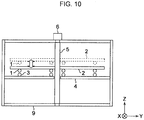
- the inductance adjusting device includes: a first coil 1, a first supporting member 2, a second coil 3, a second supporting member 4, a center shaft 5, a drive unit 6, the power feeding terminals 7a to 7d, water feeding terminals 8a to 8d, and a casing 9.
- a first coil 1 a first supporting member 2, a second coil 3, a second supporting member 4, a center shaft 5, a drive unit 6, the power feeding terminals 7a to 7d, water feeding terminals 8a to 8d, and a casing 9.
- Fig. 1A the inside of the casing 9 is illustrated fluoroscopically.
- the inductance adjusting device in this embodiment does not include a core for adjusting an inductance.
- Fig. 2A is a view illustrating one example of the first coil 1 and the first supporting member 2.
- Fig. 2B is a view illustrating one example of the second coil 3 and the second supporting member 4.
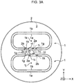
- Fig. 3A is a view illustrating the first coil 1 in a certain state and the first coil 1 in a state of being rotated by 180° about the center shaft 5 as a rotation shaft from the certain state in an overlapping manner.
- one of these two first coils 1 is illustrated by a solid line, and the other of them is illustrated by a dotted line.
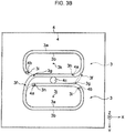
- FIG. 3B is a view illustrating the second coil 3 in a certain state and the second coil 3 in a state of being rotated by 180° about the center shaft 5 as a rotation shaft from the certain state in an overlapping manner.
- Fig. 3B similarly to Fig. 3A , for convenience of illustration, one of these two second coils 3 is illustrated by a solid line, and the other of them is illustrated by a dotted line.
- the second coil 3 does not rotate as will be described later, but in Fig. 3B , the second coil 3 is assumed to rotate.
- Fig. 2A and Fig. 3A each are a view where a surface of the first supporting member 2 facing the second supporting member 4 is seen along the Z axis in Fig. 1A .
- Fig. 2B and Fig. 3B each are a view where a surface of the second supporting member 4 facing the first supporting member 2 is seen along the Z axis in Fig. 1A .
- the arrow lines illustrated in the first coil 1 and the second coil 3 are directions of alternating currents at the same time. The directions of the alternating currents flowing through the first coil 1 and the second coil 3 will be described later with reference to Fig. 4 .
- the first supporting member 2 is a member for supporting the first coil 1.
- the first coil 1 is attached to the first supporting member 2 to be fixed on the first supporting member 2.
- holes 2a, 2b intended for attaching the first coil 1 are formed.
- the planar shape of the first supporting member 2 is circular.
- the first supporting member 2 is formed of an insulating and non-magnetic material that has strength capable of supporting the first coil 1 so as to prevent the position of the first coil 1 in the Z-axis direction from changing.
- the first supporting member 2 is formed by using a thermosetting resin, for example.
- a hole 2c intended for attaching the first supporting member 2 to the center shaft 5 is formed in the center of the first supporting member 2.
- the center shaft 5 is passed through the hole 2c, and thereby the first supporting member 2 is attached (fixed) to the center shaft 5 so as to be coaxial with the center shaft 5, and rotates with rotation of the center shaft 5.
- the first coil 1 is supported by the first supporting member 2. That is, the first coil 1 is fixed on the first supporting member 2. Therefore, the first coil 1 rotates with rotation of the first supporting member 2.
- the first coil 1 is arranged so as to make a rotation axis thereof coaxial with the center shaft 5.
- the first coil 1 has a first circumferential portion 1a, a second circumferential portion 1b, a first connecting portion 1c, a first lead-out portion Id, and a second lead-out portion 1e.
- the first circumferential portion 1a, the second circumferential portion 1b, the first connecting portion 1c, the first lead-out portion 1d, and the second lead-out portion 1e are integrated.
- the number of turns of the first coil 1 is one [turn].
- the figure of 8 in Arabic numerals is formed by the first circumferential portion 1a, the second circumferential portion 1b, and the first connecting portion 1c will be explained as an example.
- illustrations of the first lead-out portion 1d and the second lead-out portion 1e are omitted.
- the reference numeral is added to each of the first coils 1 illustrated in an overlapping manner.
- the first circumferential portion 1a is a portion circling so as to surround an inner region thereof.
- the second circumferential portion 1b is also a portion circling so as to surround an inner region thereof.
- the first circumferential portion 1a and the second circumferential portion 1b are arranged on the same horizontal plane (X-Y plane).
- the first connecting portion 1c is a portion that connects a first end 1f of the first circumferential portion 1a and a first end 1g of the second circumferential portion 1b mutually, and is a non-circumferential portion.
- the first lead-out portion 1d is connected to a second end 1h of the first circumferential portion 1a.
- the second end 1h of the first circumferential portion 1a is positioned at the hole 2b.
- the second lead-out portion 1e is connected to a second end 1i of the second circumferential portion 1b.
- the second end 1i of the second circumferential portion 1b is positioned at the hole 2a.
- the first lead-out portion 1d and the second lead-out portion 1e each become a lead-out wire for connecting the first coil 1 to an external part.
- the first lead-out portion 1d and the second lead-out portion 1e are each illustrated by a dotted line, to thereby indicate that the first lead-out portion 1d and the second lead-out portion 1e exist on a surface opposite to the surface of the first supporting member 2 illustrated in Fig. 2A .
- the first coil 1 is brought into a state illustrated by a dotted line from a state illustrated by a solid line when being rotated about the center shaft 5 as a rotation shaft by 180° .
- the center shaft 5 is arranged in the hole 2c.
- the center shaft 5 is arranged at a position including the middle position between the center 1j of the first circumferential portion 1a and the center 1k of the second circumferential portion 1b.
- the first circumferential portion 1a and the second circumferential portion 1b are positioned on the sides opposite to each other across the hole 2c (center shaft 5). That is, the first circumferential portion 1a and the second circumferential portion 1b are arranged so as to maintain a state where the first coil 1 is displaced by 180° in terms of angle in its rotation direction.
- This angle is an angle formed by a virtual straight line mutually connecting the center of the hole 2c (shaft core of the center shaft 5) and the center 1j of the first circumferential portion 1a by the most direct way and a virtual straight line mutually connecting the center of the hole 2c (shaft core of the center shaft 5) and the center 1k of the second circumferential portion 1b by the most direct way.
- the center 1j of the first circumferential portion 1a and the center 1k of the second circumferential portion 1b are points illustrated virtually, and are not existent points.
- the first circumferential portion 1a, the second circumferential portion 1b, a third circumferential portion 3a, and a fourth circumferential portion 3b are most preferred to be the same completely in shape and size. However, as illustrated in Fig. 2A and Fig. 2B , it is sometimes impossible to make the first circumferential portion 1a, the second circumferential portion 1b, the third circumferential portion 3a, and the fourth circumferential portion 3b the same completely in shape and size.
- the present inventors changed, of various inductance adjusting devices including inductance adjusting devices in first to fifth embodiments, the sizes of the first coil and the second coil, the gap (interval in the Z-axis direction) between the first coil and the second coil, the shapes of the first coil and the second coil, and so on, to then measure variable magnifications ⁇ .
- the first circumferential portion, the second circumferential portion, the third circumferential portion, and the fourth circumferential portion were set the same completely in shape and size.
- the variable magnification ⁇ ranged from about 2.3 to 5.6 magnifications.
- a coupling coefficient k corresponding to this range ranges from about 0.4 to 0.7.
- the coupling coefficient k is expressed by (2) Equation to be described later.
- This standard coupling coefficient ks becomes a representative value of the coupling coefficient in the case where the first circumferential portion, the second circumferential portion, the third circumferential portion, and the fourth circumferential portion are the same completely in shape and size.
- a minimum value ⁇ min of the variable magnification ⁇ of a combined inductance GL when seen from an alternating-current power supply circuit is assumed to be 2.0.
- the variable magnification ⁇ of the combined inductance GL when seen from the alternating-current power supply circuit is expressed by (4) Equation to be described later.
- a minimum value kmin of the coupling coefficient between the first coil and the second coil becomes about 0.33.
- the shapes and the sizes of the first circumferential portion, the second circumferential portion, the third circumferential portion, and the fourth circumferential portion only need to be the same in a portion of 60% of the total length of these.
- the minimum value ⁇ min of the variable magnification ⁇ is preferred to be 2,5 and more preferred to be 3.0 practically.
- the shapes and the sizes of the first circumferential portion, the second circumferential portion, the third circumferential portion, and the fourth circumferential portion are preferred to be the same in a portion of 78% of the total length of these, and more preferred to be the same in a region of 91% or more.
- first circumferential portion 1a, the second circumferential portion 1b, the third circumferential portion 3a, and the fourth circumferential portion 3b are the same in a portion of 60% or more of the total length of these, it is possible to regard the first circumferential portion 1a, the second circumferential portion 1b, the third circumferential portion 3a, and the fourth circumferential portion 3b as being the same in shape and size.
- 60% is preferred to be 78%, and more preferred to be 91% according to the minimum value ⁇ min of the variable magnification ⁇ .
- a portion having a length of 60% or more of the entire length of the first circumferential portion 1a overlaps with a region where the second circumferential portion 1b existed before the aforementioned rotation.
- the entire length of the first circumferential portion 1a is a length from the first end If to the second end 1h of the first circumferential portion 1a.
- Fig. 3A when it is set that the state illustrated by the solid line is brought into the state illustrated by the dotted line, in Fig. 3A , the portion having a length of 60% or more of the entire length of the first circumferential portion 1a illustrated by a dotted line on the lower side overlaps with the second circumferential portion 1b illustrated by a solid line on the lower side.
- a portion having a length of 60% or more of the entire length of the second circumferential portion 1b overlaps with a region where the first circumferential portion 1a existed before the aforementioned rotation.
- the entire length of the second circumferential portion 1b is a length from the first end 1g to the second end 1i of the second circumferential portion 1b.
- Fig. 3A when it is set that the state illustrated by the solid line is brought into the state illustrated by the dotted line, in Fig. 3A , the portion having a length of 60% or more of the entire length of the second circumferential portion 1b illustrated by a dotted line on the upper side overlaps with the first circumferential portion 1a illustrated by a solid line on the upper side.
- 60% is preferred to be 78%, and more preferred to be 91% according to the minimum value ⁇ min of the variable magnification ⁇ .
- the second supporting member 4 is a member for supporting the second coil 3.
- the second coil 3 is attached to the second supporting member 4 to be fixed on the second supporting member 4.
- holes 4a, 4b intended for attaching the second coil 3 are formed.
- the planar shape of the second supporting member 4 is rectangular.
- the second supporting member 4 is formed of an insulating and non-magnetic material that has strength capable of supporting the second coil 3 so as to prevent the position of the second coil 3 in the Z-axis direction from changing.
- the second supporting member 4 is formed by using a thermosetting resin, for example.
- the second supporting member 4 is attached to the casing 9 so as to be coaxial with the center shaft 5 and is fixed to the casing 9.
- a hole 4c intended for arranging the second supporting member 4 coaxially with the center shaft 5.
- the hole 4c is formed so as to have an interval between the second supporting member 4 and the center shaft 5 when the center shaft 5 is passed through the hole 4c. In this manner, even when the center shaft 5 rotates, the second supporting member 4 is brought into a state of being fixed to the casing 9 without rotation.
- the second coil 3 has the third circumferential portion 3a, the fourth circumferential portion 3b, a second connecting portion 3c, a third lead-out portion 3d, and a fourth lead-out portion 3e.
- the third circumferential portion 3a, the fourth circumferential portion 3b, the second connecting portion 3c, the third lead-out portion 3d, and the fourth lead-out portion 3e are integrated.
- the number of turns of the second coil 3 is one [turn].
- the figure of 8 in Arabic numerals is formed by the third circumferential portion 3a, the fourth circumferential portion 3b, and the second connecting portion 3c will be explained as an example.
- illustrations of the third lead-out portion 3d and the fourth lead-out portion 3e are omitted.
- the reference numeral is added to each of the second coils 3 illustrated in an overlapping manner.
- the third circumferential portion 3a is a portion circling so as to surround an inner region thereof.
- the fourth circumferential portion 3b is also a portion circling so as to surround an inner region thereof.
- the third circumferential portion 3a and the fourth circumferential portion 3b are arranged on the same horizontal plane (X-Y plane).
- the second connecting portion 3c is a portion that connects a first end 3f of the third circumferential portion 3a and a first end 3g of the fourth circumferential portion 3b mutually, and is a non-circumferential portion.
- the third lead-out portion 3d is connected to a second end 3h of the third circumferential portion 3a.
- the second end 3h of the third circumferential portion 3a is positioned at the hole 4a.
- the fourth lead-out portion 3e is connected to a second end 3i of the fourth circumferential portion 3b.
- the second end 3i of the fourth circumferential portion 3b is positioned at the hole 4b.
- the third lead-out portion 3d and the fourth lead-out portion 3e each become a lead-out wire for connecting the second coil 3 to an external part.
- the third lead-out portion 3d and the fourth lead-out portion 3e are each illustrated by a dotted line, to thereby indicate that the third lead-out portion 3d and the fourth lead-out portion 3e exist on a surface opposite to the surface of the second supporting member 4 illustrated in Fig. 2B .
- the second coil 3 does not rotate. However, in Fig. 3B , it is assumed that the second coil 3 rotates about the center shaft 5 as a rotation shaft. Then, the second coil 3 is brought into a state illustrated by a dotted line from a state illustrated by a solid line by rotating about the center shaft 5 as a rotation shaft by 180°.
- the center shaft 5 is arranged in the hole 4c.
- the center shaft 5 is arranged at a position including the middle position between the center 3j of the third circumferential portion 3a and the center 3k of the fourth circumferential portion 3b.
- the third circumferential portion 3a and the fourth circumferential portion 3b are positioned on the sides opposite to each other across the hole 4c (center shaft 5). That is, the third circumferential portion 3a and the fourth circumferential portion 3b are arranged so as to maintain a state where the first coil 1 is displaced by 180° in terms of angle in its rotation direction.
- This angle is an angle formed by a virtual straight line mutually connecting the center of the hole 4c (shaft core of the center shaft 5) and the center 3j of the third circumferential portion 3a by the most direct way and a virtual straight line mutually connecting the center of the hole 4c (shaft core of the center shaft 5) and the center 3k of the fourth circumferential portion 3b by the most direct way.
- the center 3j of the third circumferential portion 3a and the center 3k of the fourth circumferential portion 3b are points illustrated virtually, and are not existent points.
- the center shaft 5 is arranged at the position including the middle position between the center 1j of the first circumferential portion 1a and the center 1k of the second circumferential portion 1b and the position including the middle position between the center 3j of the third circumferential portion 3a and the center 3k of the fourth circumferential portion 3b.
- the center shaft 5 passes through the middle position between the center 1j of the first circumferential portion 1a and the center 1k of the second circumferential portion 1b and the middle position between the center 3j of the third circumferential portion 3a and the center 3k of the fourth circumferential portion 3b.
- the center shaft 5 extends in the Z-axis direction.
- a portion having a length of 60% or more of the entire length of the third circumferential portion 3a overlaps with a region where the fourth circumferential portion 3b existed before the aforementioned rotation.
- the entire length of the third circumferential portion 3a is a length from the first end 3f to the second end 3h of the third circumferential portion 3a.
- a portion having a length of 60% or more of the entire length of the fourth circumferential portion 3b overlaps with a region where the third circumferential portion 3a existed before the aforementioned rotation.
- the entire length of the fourth circumferential portion 3b is a length from the first end 3g to the second end 3i of the fourth circumferential portion 3b.
- Fig. 3B when it is set that the state illustrated by the solid line is brought into the state illustrated by the dotted line, in Fig. 3B , the portion having a length of 60% or more of the entire length of the fourth circumferential portion 3b illustrated by a dotted line on the lower side overlaps with the third circumferential portion 3a illustrated by a solid line on the lower side.
- 60% is preferred to be 78%, and more preferred to be 91% according to the minimum value ⁇ min of the variable magnification ⁇ .
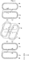
- Fig. 4 is a view illustrating one example of the positional relationship between the first coil 1 and the second coil 3.
- an arrangement of the first coil 1 and the second coil 3 when the combined inductance GL by the first coil 1 and the second coil 3 becomes the minimum value is illustrated.
- an arrangement of the first coil 1 and the second coil 3 when the combined inductance GL by the first coil 1 and the second coil 3 becomes the maximum value is illustrated.
- an arrangement of the first coil 1 and the second coil 3 when the combined inductance GL by the first coil 1 and the second coil 3 becomes an intermediate value (value greater than the minimum value and lower than the maximum value) is illustrated.
- the first coil 1 is illustrated by a solid line
- the second coil 3 is illustrated by a dotted line.
- the arrow lines indicated by a solid line and a dotted line indicate the directions of alternating currents flowing through the first coil 1 and the second coil 3 (in the case of being seen from the same direction at the same time) respectively.
- the state illustrated on the bottom of Fig. 4 is set as a first state. Further, the state illustrated on the top of Fig. 4 is set as a second state.
- the first state is a state where the first circumferential portion 1a of the first coil 1 and the third circumferential portion 3a of the second coil 3 are at positions facing each other and the second circumferential portion 1b of the first coil 1 and the fourth circumferential portion 3b of the second coil 3 are at positions facing each other.
- the second state is a state where the first circumferential portion 1a of the first coil 1 and the fourth circumferential portion 3b of the second coil 3 are at positions facing each other and the second circumferential portion 1b of the first coil 1 and the third circumferential portion 3a of the second coil 3 are at positions faring each other.
- the portion having a length of 60% or more of the entire length of the first circumferential portion 1a and the portion having a length of 60% or more of the entire length of the third circumferential portion 3a overlap with each other.
- the portion having a length of 60% or more of the entire length of the second circumferential portion 1b and the portion having a length of 60% or more of the entire length of the fourth circumferential portion 3b overlap with each other.
- the portion having a length of 60% or more of the entire length of the first circumferential portion 1a and the portion having a length of 60% or more of the entire length of the fourth circumferential portion 3b overlap with each other.
- the portion having a length of 60% or more of the entire length of the second circumferential portion 1b and the portion having a length of 60% or more of the entire length of the third circumferential portion 3a overlap with each other.
- 60% is preferred to be 78%, and more preferred to be 91% according to the minimum value ⁇ min of the variable magnification ⁇ .
- each length of the first connecting portion 1c and the second connecting portion 3c is shorter as compared to each length of the first circumferential portion 1a, the second circumferential portion 1b, the third circumferential portion 3a, and the fourth circumferential portion 3b.
- it is little different substantially even when the shapes and the sizes of the first coil 1 (the first circumferential portion 1a, the second circumferential portion 1b, and the first connecting portion 1c) and the second coil 3 (the third circumferential portion 3a, the fourth circumferential portion 3b, and the second connecting portion 3c) are the same in the portion of 60% or more (preferably 78% or more, more preferably 91% or more) of the total length of these.
- the aforementioned prescription made in the aforementioned explanation may be made with the shapes and the sizes of the first coil 1 (the first circumferential portion 1a, the second circumferential portion 1b, and the first connecting portion 1c) and the second coil 3 (the third circumferential portion 3a, the fourth circumferential portion 3b, and the second connecting portion 3c), in place of the shapes and the sizes of the first circumferential portion 1a, the second circumferential portion 1b, the third circumferential portion 3a, and the fourth circumferential portion.
- the first coil 1 and the second coil 3 are formed by using a water-cooled cable.
- the water-cooled cable includes a hose and an electric wire passing through the inside of the hose, for example.
- the hose and the electric wire both are set to have flexibility.
- the first coil 1 and the second coil 3 also have flexibility.
- the hose is formed of an insulating material.
- the electric wire may be formed of a single wire, or may also be formed of a plurality of wires. In the case where the electric wire is formed of a plurality of wires, the electric wire may be set to a Litz wire, for example.
- coil surfaces of the first coil 1 and the second coil 3 are designed to be parallel in a state of having constant intervals G therebetween when the first coil 1 and the second coil 3 are arranged as illustrated in Fig. 1A .
- the size of the interval G can be set according to the maximum value of the inductance changeable in the inductance adjusting device, or the like, for example.
- the coil surface of the first coil 1 is a horizontal plane (X-Y plane) in a region surrounded by the first circumferential portion 1a and the second circumferential portion 1b.
- the coil surface of the second coil 3 is a horizontal plane (X-Y plane) in a region surrounded by the third circumferential portion 3a and the fourth circumferential portion 3b.
- the center shaft 5 is to rotate the first coil 1.
- the center shaft 5 is rotatably attached to the casing 9 via a bearing or the like.
- the drive unit 6 is a driving source for rotating the center shaft 5, and includes a motor and so on.
- the power feeding terminals 7a to 7d are terminals for supplying alternating-current power, which is supplied from the not-illustrated alternating-current power supply circuit, to the first coil 1 and the second coil 3. As illustrated in Fig. 1A and Fig. 1B , the power feeding terminals 7a to 7d are attached (fixed) to the casing 9 so that their tip-side regions are exposed.
- the not-illustrated alternating-current power supply circuit is electrically connected to the power feeding terminals 7a, 7c. Further, the power feeding terminals 7b and 7d are electrically connected to each other.
- the first coil 1 and the second coil 3 are connected in series. That is, the alternating current supplied from the alternating-current power supply circuit flows through a path of the "alternating-current power supply circuit ⁇ the power feeding terminal 7a ⁇ the first coil 1 ⁇ the power feeding terminal 7d ⁇ the power feeding terminal 7b ⁇ the second coil 3 ⁇ the power feeding terminal 7c ⁇ the alternating-current power supply circuit" and a path of the "alternating-current power supply circuit ⁇ the power feeding terminal 7c ⁇ the second coil 3 ⁇ the power feeding terminal 7b ⁇ the power feeding terminal 7d ⁇ the first coil 1 ⁇ the power feeding terminal 7a ⁇ the alternating-current power supply circuit" alternately.
- the directions (when seen from the same direction) of the alternating currents flowing through linear portions on the center shaft 5 side of the first circumferential portion 1a and the second circumferential portion 1b of the first coil 1 (at the same time) become the same (see the arrow lines added to the first coil 1 in Fig. 2A ).
- the directions (when seen from the same direction) of the alternating currents flowing through linear portions on the center shaft 5 side of the third circumferential portion 3a and the fourth circumferential portion 3b of the second coil 3 (at the same time) become the same (see the arrow lines added to the second coil 3 in Fig. 2B ).
- the power feeding terminals 7a to 7d each have a hollow portion.
- these hollow portions and the insides of the hoses forming the first coil 1 and the second coil 3 communicate with each other.
- the water feeding terminals 8a to 8d are terminals for supplying a cooling water, which is supplied by using a not-illustrated pump, or the like, into the insides of the first coil 1 and the second coil 3.
- the insides of the first coil 1 and the second coil 3 mean the insides of the hoses forming the first coil 1 and the second coil 3.
- the water feeding terminals 8a to 8d each have a hollow portion.
- the water feeding terminals 8a to 8d are attached to the tip-side regions of the power feeding terminals 7a to 7d (regions exposed from the casing 9) respectively so that the hollow portions of the power feeding terminals 7a to 7d and the hollow portions of the water feeding terminals 8a to 8d communicate with each other.
- the water feeding terminals 8b and 8d are connected to each other by a not-illustrated hose.
- a not-illustrated hose for supplying the cooling water is attached to each of the water feeding terminals 8a and 8c.
- the cooling water flows out from and flows into the water feeding terminals 8a, 8c through the hoses attached to the water feeding terminals 8a, 8c.
- the inductance in the inductance adjusting device is the combined inductance GL by the first coil 1 and the second coil 3.
- the combined inductance GL by the first coil 1 and the second coil 3 is set to the inductance when seen from the aforementioned alternating-current power supply circuit.
- the combined inductance GL by the first coil 1 and the second coil 3 will be abbreviated as the combined inductance GL as necessary.
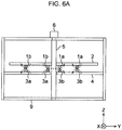
- Fig. 5A, Fig. 5B , Fig. 6A , and Fig. 6B are views each illustrating one example of directions of magnetic fluxes to occur when the alternating current is applied to the first coil 1 and the second coil 3.
- the directions of the magnetic fluxes are illustrated together with circuit symbols indicating the first coil 1 and the second coil 3.
- the directions of the magnetic fluxes are illustrated together with the first coil 1 and the second coil 3 in a state of being arranged in the inductance adjusting device.
- Fig. 5A and Fig. 6A are views each illustrating the directions of the magnetic fluxes when the combined inductance GL becomes the minimum value.
- Fig. 5B and Fig. 6B are views each illustrating the directions of the magnetic fluxes when the combined inductance GL becomes the maximum value.
- the arrows attached to the first coil 1 and the second coil 3 each indicate the direction of the alternating current.
- the arrow lines passing through the first coil 1 and the second coil 3 each indicate the direction of the magnetic flux.
- the marks of ⁇ and ⁇ each added inside ⁇ indicate the direction of the alternating current.
- the mark of ⁇ added inside ⁇ indicates the direction from the far side of the sheet toward the near side
- the mark of ⁇ added inside ⁇ indicates the direction from the near side of the sheet toward the far side.
- the arrow lines indicated by a dotted line in Fig. 6A and the loops indicated by a solid line together with the arrows in Fig. 6B indicate the directions of the magnetic fluxes.
- the first circumferential portion 1a of the first coil 1 and the fourth circumferential portion 3b of the second coil 3 are faced to each other, and the second circumferential portion 1b of the first coil 1 and the third circumferential portion 3a of the second coil 3 are faced to each other.
- the direction of the alternating current flowing through the first circumferential portion 1a of the first coil 1 and the direction of the alternating current flowing through the fourth circumferential portion 3b of the second coil 3 are opposite.
- the direction of the alternating current flowing through the second circumferential portion 1b of the first coil 1 and the direction of the alternating current flowing through the third circumferential portion 3a of the second coil 3 are opposite.
- the combined inductance GL in this case is expressed by (1) Equation below when a self-inductance of the first coil 1 is set to L1, a self-inductance of the second coil 3 is set to L2, and a mutual inductance of the first coil 1 and the second coil 3 is set to M.
- GL L 1 + L 2 ⁇ 2 ⁇ M
- the combined inductance GL expressed by (1) Equation becomes the minimum value of the combined inductance GL.
- the mutual, inductance M of the first coil 1. and the second coil 3 is expressed by (2) Equation below when the coupling coefficient between the first coil 1 and the second coil 3 is set to k.
- M ⁇ k L 1 ⁇ L 2
- the magnetic fluxes to occur by applying the alternating current to the first coil 1 and the second coil 3 are as illustrated in Fig. 6A .
- the first state illustrated on the bottom of Fig. 4 is a state where the first coil 1 is rotated by 180° from the second state illustrated on the top of Fig. 4 .
- the first circumferential portion 1a of the first coil 1 and the third circumferential portion 3a of the second coil 3 are faced to each other, and the second circumferential portion 1b of the first coil 1 and the fourth circumferential portion 3b of the second coil 3 are faced to each other.
- the direction of the alternating current flowing through the first circumferential portion 1a of the first coil 1 and the direction of the alternating current flowing through the third circumferential portion 3a of the second coil 3 are the same.
- the direction of the alternating current flowing through the second circumferential portion 1b of the first coil 1 and the direction of the alternating current flowing through the fourth circumferential portion 3b of the second coil 3 are the same.
- the combined inductance GL expressed by (3) Equation becomes the maximum value of the combined inductance GL.
- the drive unit 6 rotates the first coil 1 within a range of 0° to 180°.
- the rotation angle of the first coil. 1 described below is also set to the angle in the case where the rotation angle of the first coil 1 in the second state illustrated on the top of Fig. 4 is set to 0°.
- the state illustrated in the middle of Fig. 4 is the state between the state illustrated on the top of Fig. 4 and the state illustrated on the bottom of Fig. 4 .
- the combined inductance GL in this state indicates the value between the maximum value expressed by (3) Equation and the minimum value expressed by (1) Equation. This value is determined according to the rotation angle of the first coil 1.
- the combined inductance GL is changed by rotating the first coil 1 in this manner, thereby making it possible to adjust the inductance of the electric circuit to which the inductance adjusting device is connected online.
- variable magnification ⁇ of the combined inductance GL when seen from the alternating-current power supply circuit is expressed by the value obtained by dividing the combined inductance GL in the case of the rotation angle of the first coil 1 being 180° by the combined inductance GL in the case of the rotation angle of the first coil 1 being 0°.
- the variable magnification ⁇ of the combined inductance GL when seen from the alternating-current power supply circuit is expressed by (4) Equation below.
- the coupling coefficient k between the first coil 1 and the second coil 3 is expressed by (5) Equation below.
- the variable magnification ⁇ of the combined inductance GL when seen from the alternating-current power supply circuit can be made 3 or more.
- Increasing the coupling coefficient k between the first coil 1 and the second coil 3 makes it possible to increase the variable magnification ⁇ of the combined inductance GL when seen from the alternating-current power supply circuit.
- the shapes, the sizes, and the relative positions of the first coil 1 and the second coil 3 are preferably determined so that the coupling coefficient k between the first coil 1 and the second coil 3 increases.
- the first coil 1 is rotated, to thereby adjust the combined inductance GL.
- changing the occupancy ratio of the magnetic body in the solenoid coil like the technique described in Patent Literature 1 is no longer required, and further, extending and contracting the coil like the technique described in Patent Literature 2 is also no longer required. Accordingly, it is possible to simplify the structure of the inductance adjusting device and at the same time, downsize the inductance adjusting device. This leads to the reduction in cost of the inductance adjusting device.
- the coil surface of the first coil 1 and the coil surface of the second coil 3 are parallel. Further, the first coil 1 (the first circumferential portion 1a and the second circumferential portion 1b) and the second coil 3 (the third circumferential portion 3a and the fourth circumferential portion 3b) are arranged at the positions opposite to each other across the center shaft 5 (positions to be 2-fold symmetry). Further, the first circumferential portion 1a, the second circumferential portion 1b, the third circumferential portion 3a, and the fourth circumferential portion 3b are the same in size and shape.
- the first supporting member 2 and the second supporting member 4 each only need to have strength capable of supporting the first coil 1 and the second coil 3 so as to prevent the positions in the Z-axis direction from being displaced as much as possible. Therefore, it is possible to easily design the strengths of the first supporting member 2 and the second supporting member 4.
- the two coils each have only one coaxial circumferential portion.
- the rotation angle of the other coil corresponding to one coil becomes larger than 90° , the two coils no longer overlap with each other. Therefore, the rate of change of magnitude of a mutual inductance of the two coils (change per unit angle) decreases.
- the change of the inductance is proportional to the logarithm of the rotation angle.
- the mutual inductance M of the first coil 1 and the second coil 3 can be changed in the same manner in the range of 0° to 90° and in the range of 90° to 180° in terms of the rotation angle of the first coil 1 except the reference numerals and symbols.
- the relationship between the magnitude of the combined inductance GL and the rotation angle of the first coil 1 exhibits a linear relationship better than that in the technique described in Patent Literature 3. Accordingly, it is possible to perform the frequency control with high accuracy.
- Fig. 7A is a view illustrating one example of the relationship between an inductance and a rotation angle in the inductance adjusting device in this embodiment.
- the inductance is the combined inductance GL and the rotation angle is the rotation angle of the first coil 1.
- Fig. 7B is a view illustrating one example of the relationship between an inductance and a rotation angle in the technique described in Patent Literature 3.
- the inductance is the combined inductance of the two coils described in Patent Literature 3
- the rotation angle is the sum of absolute values of angles when the two coils rotate about the coil ends as a shaft.
- the rate of change of the inductance to change of the rotation angle (namely, the gradient of the graph illustrated in Fig. 7A ) becomes constant generally regardless of the rotation angle.
- the rate of change of the inductance to change of the rotation angle increases.
- the rate of change of the inductance to change of the rotation angle decreases.
- adjustment of the inductance is no longer easy.
- the shape formed by the first circumferential portion, the second circumferential portion, and the first connecting portion is not limited to the figure of 8 in Arabic numerals.
- the shape formed by the third circumferential portion, the fourth circumferential portion, and the second connecting portion is also not limited to the figure of 8 in Arabic numerals.
- such shapes as illustrated in Fig. 8A and Fig. 8B may be applied.
- Fig. 8A is a view illustrating a first modified example of a first coil 81 and a first supporting member 82.
- Fig. 8B is a view illustrating a first modified example of a second coil 83 and a second supporting member 84.
- Fig. 8A is a view corresponding to Fig. 2A
- Fig. 8B is a view corresponding to Fig. 2B .
- the first supporting member 82 is a member for supporting the first coil 81.
- the first coil 81 is attached to the first supporting member 82 to be fixed on the first supporting member 82.
- holes 82a, 82b intended for attaching the first coil 81 are formed in the first supporting member 82.
- a hole 82c intended for attaching the first supporting member 82 to a center shaft 5 is formed in the first supporting member 82.
- the first coil 81 and the first supporting member 82 rotate with rotation of the first supporting member 82.
- the first supporting member 82 can be fabricated by the same one as that of the first supporting member 2 illustrated in Fig. 2A .
- the first coil 81 has a first circumferential portion 81a, a second circumferential portion 81b, a first connecting portion 81c, a first lead-out portion 81d, and a second lead-out portion 81e.
- the first circumferential portion 81a, the second circumferential portion 81b, the first connecting portion 81c, the first lead-out portion 81d, and the second lead-out portion 81e are integrated.
- the first circumferential portion 81a is a portion circling so as to surround an inner region thereof.
- the second circumferential portion 81b is also a portion circling so as to surround an inner region thereof.
- the first circumferential portion 81a and the second circumferential portion 81b are arranged on the same horizontal plane (X-Y plane).
- the first connecting portion 81c is a portion that connects a first end 81f of the first circumferential portion 81a and a first end 81g of the second circumferential portion 81b mutually, and is a non-circumferential portion.
- the first lead-out portion 81d is connected to a second end 81h of the first circumferential portion 81a.
- the second end 81h of the first circumferential portion 81a is positioned at the hole 82b.
- the second lead-out portion 81e is connected to a second end 81i of the second circumferential portion 81b.
- the second end 81i of the second circumferential portion 81b is positioned at the hole 82a.
- the second supporting member 84 is a member for supporting the second coil 83.
- the second supporting member 84 is attached to a casing 9 so as to be coaxial with the center shaft 5 and is fixed to the casing 9.
- the second coil 83 is attached to the second supporting member 84 to be fixed on the second supporting member 84.
- holes 84a, 84b intended for attaching the second coil 83 are formed in the second supporting member 84.
- a hole 84c intended for arranging the second supporting member 84 coaxially with the center shaft 5.
- the hole 84c is formed so as to have an interval between the second supporting member 84 and the center shaft 5 when the center shaft 5 is passed through the hole 84c. In this manner, even when the center shaft 5 rotates, the second supporting member 84 is brought into a state of being fixed to the casing 9 without rotation.
- the second supporting member 84 can be fabricated by the same one as that of the second supporting member 4 illustrated in Fig. 2B .
- the second coil 83 has a third circumferential portion 83a, a fourth circumferential portion 83b, a second connecting portion 83c, a third lead-out portion 83d, and a fourth lead-out portion 83e.
- the third circumferential portion 83a, the fourth circumferential portion 83b, the second connecting portion 83c, the third lead-out portion 83d, and the fourth lead-out portion 83e are integrated.
- the third circumferential portion 83a is a portion circling so as to surround an inner region thereof.
- the fourth circumferential portion 83b is also a portion circling so as to surround an inner region thereof.
- the third circumferential portion 83a and the fourth circumferential portion 83b are arranged on the same horizontal plane (X-Y plane).
- the second connecting portion 83c is a portion that connects a first end 83f of the third circumferential portion 83a and a first end 83g of the fourth circumferential portion 83b mutually, and is a non-circumferential portion.
- the third lead-out portion 83d is connected to a second end 83h of the third circumferential portion 83a.
- the second end 83h of the third circumferential portion 83a is positioned at the hole 84a.
- the fourth lead-out portion 83e is connected to a second end 83i of the fourth circumferential portion 83b.
- the second end 83i of the fourth circumferential portion 83b is positioned at the hole 84b.
- the outermost peripheral contour shapes of the first circumferential portion, the second circumferential portion, the third circumferential portion, and the fourth circumferential portion may be another shape (for example, a perfect circle, an oval, or a rectangle).
- connection between the first circumferential portion and the second circumferential portion and the connection between the third circumferential portion and the fourth circumferential portion are not limited to the connections illustrated in Fig. 2A and Fig. 2B . That is, the directions of the alternating currents flowing through the first circumferential portion and the second circumferential portion and the directions of the alternating currents flowing through the third circumferential portion and the fourth circumferential portion are not limited to the directions illustrated in Fig. 2A and Fig. 2B .
- Fig. 9A is a view illustrating a second modified example of a first coil 91 and a first supporting member 92.
- Fig. 9B is a view illustrating a second modified example of a second coil 93 and a second supporting member 94.
- Fig. 9A is a view corresponding to Fig. 2A
- Fig. 9B is a view corresponding to Fig. 2B .
- the first supporting member 92 is a member for supporting the first coil 91.
- the first coil 91 is attached to the first supporting member 92 to be fixed on the first supporting member 92.
- holes 92a, 92b intended for attaching the first coil 91 are formed in the first supporting member 92.
- a hole 92c intended for attaching the first supporting member 92 to a center shaft 5 is formed in the first supporting member 92.
- the first coil 91 and the first supporting member 92 rotate with rotation of the first supporting member 92.
- the first supporting member 92 can be fabricated by the same one as that of the first supporting member 2 illustrated in Fig. 2A .
- the first coil 91 has a first circumferential portion 91a, a second circumferential portion 91b, a first connecting portion 91c, a first lead-out portion 91d, and a second lead-out portion 91e.
- the first circumferential portion 91a, the second circumferential portion 91b, the first connecting portion 91c, the first lead-out portion 91d, and the second lead-out portion 91e are integrated.
- the first circumferential portion 91a is a portion circling so as to surround an inner region thereof.
- the second circumferential portion 91b is also a portion circling so as to surround an inner region thereof.
- the first circumferential portion 91a and the second circumferential portion 91b are arranged on the same horizontal plane (X-Y plane).
- the first connecting portion 91c is a portion that connects a first end 91f of the first circumferential portion 91a and a first end 91g of the second circumferential portion 91b mutually, and is a non-circumferential portion.
- the first lead-out portion 91d is connected to a second end 91h of the first circumferential portion 91a.
- the second end 91h of the first circumferential portion 91a is positioned at the hole 92b.
- the second lead-out portion 91e is connected to a second end 91i of the second circumferential portion 91b.
- the second end 91i of the second circumferential portion 91b is positioned at the hole 92a.
- the second supporting member 94 is a member for supporting the second coil 93.
- the second supporting member 94 is attached (fixed) to a casing 9 so as to be coaxial with the center shaft 5.
- the second coil 93 is attached to the second supporting member 94 to be fixed on the second supporting member 94.
- holes 94a, 94b intended for attaching the second coil 93 are formed in the second supporting member 94.
- a hole 94c intended for arranging the second supporting member 4 coaxially with the center shaft 5.
- the hole 94c is formed so as to have an interval between the second supporting member 94 and the center shaft 5 when the center shaft 5 is passed through the hole 94c.
- the second supporting member 94 can be fabricated by the same one as that of the second supporting member 4 illustrated in Fig. 2B .
- the second coil 93 has a third circumferential portion 93a, a fourth circumferential portion 93b, a second connecting portion 93c, a third lead-out portion 93d, and a fourth lead-out portion 93e.
- the third circumferential portion 93a, the fourth circumferential portion 93b, the second connecting portion 93c, the third lead-out portion 93d, and the fourth lead-out portion 93e are integrated.
- the third circumferential portion 93a is a portion circling so as to surround an inner region thereof.
- the fourth circumferential portion 93b is also a portion circling so as to surround an inner region thereof.
- the third circumferential portion 93a and the fourth circumferential portion 93b are arranged on the same horizontal plane (X-Y plane).
- the second connecting portion 93c is a portion that connects a first end 93f of the third circumferential portion 93a and a first end 93g of the fourth circumferential portion 93b mutually, and is a non-circumferential portion.
- the third lead-out portion 93d is connected to a second end 93h of the third circumferential portion 93a.
- the second end 93h of the third circumferential portion 93a is positioned at the hole 94a.
- the fourth lead-out portion 93e is connected to a second end 93i of the fourth circumferential portion 93b.
- the second end 93i of the fourth circumferential portion 93b is positioned at the hole 94b.
- the current flows counterclockwise in the first circumferential portion 1a
- the current flows clockwise in the second circumferential portion 1b
- the current flows clockwise in the third circumferential portion 3a
- the current flows counterclockwise in the fourth circumferential portion 3b with respect to the sheets of Fig. 2A and Fig. 2B .
- the directions of the currents flowing through the two circumferential portions are opposite.
- the current flows clockwise in the first circumferential portion 91a and the second circumferential portion 91b, and the current flows counterclockwise in the third circumferential portion 93a and the fourth circumferential portion 93b with respect to the sheets of Fig. 9A and Fig. 9B .
- the directions of the currents flowing through the two circumferential portions are the same (see the arrow lines illustrated beside the first coil 91 and the second coil 93 in Fig. 9A and Fig.
- variable magnification ⁇ of the combined inductance GL when seen from the alternating-current power supply circuit in the case illustrated in Fig. 9A and Fig. 9B differs from that in the case of the structure illustrated in Fig. 2A and Fig. 2B , but the principle that changes the combined inductance GL is the same in all the structures illustrated in Fig. 2A , Fig. 2B and Fig. 9A , Fig. 9B .
- the drive unit 6 there may be provided a drive unit that rotates the first supporting member 2 so that the first coil 1 rotates substantially coaxially with the center shaft 5. That is, the drive unit may be attached not to the center shaft 5, but to the first supporting member 2.
- the second coil 3 may be rotated in addition to the first coil 1.
- a drive unit that rotates the second supporting member 4 coaxially with the center shaft 5 is required.
- the total of the absolute value of the rotation angle of the first coil 1 in a first direction (for example, clockwise direction) and the absolute value of the rotation angle of the second coil 3 in a second direction (direction opposite to the first direction, for example, counterclockwise direction) preferably ranges from 0° to 180° (namely, the maximum value of the total is preferably set to 180°).
- the first coil 1 and the second coil 3 are both rotated, thereby making it possible to continuously obtain the first state illustrated on the bottom of Fig. 4 , the second state illustrated on the top of Fig. 4 , and the state between these states.
- first coil 1 and the second coil 3 may be connected in parallel.
- first coil 1 and the second coil 3 may be connected in parallel.
- out of the both end portions of the first coil 1, one end portion led out through the hole 2a of the first supporting member 2 (the second end li of the second circumferential portion 1b) and out of the both end portions of the second coil 3, one end portion led out through the hole 4a of the second supporting member 4 (the second end 3h of the third circumferential portion 3a) can be electrically connected to each other, and at the same time, out of the both end portions of the first coil 1, the other end portion led out through the hole 2b of the first supporting member 2 (the second end 1h of the first circumferential portion 1a) and out of the both end portions of the second coil 3, the other end portion led out through the hole 4b of the second supporting member 4 (the second end 3i of the fourth circumferential portion 3b) can be electrically connected to each other.
- the alternating-current power is designed to be supplied to these connected portions from the not-illustrated alternating-current power supply circuit.
- the alternating-current power supply circuit can be connected to the power feeding terminals 7a, 7b.
- the self-inductances L1, L2 of the first coil 1 and the second coil 3 are set to L in order to simplify the explanation.
- first coil 1 and the second coil 3 are arranged so as to make their coil surfaces substantially parallel to each other in a state of having the constant intervals G therebetween has been explained as an example.
- this embodiment is not necessarily required to be structured in this manner, and the interval G may be varied by moving at least one of the first coil 1 and the second coil 3 in the Z-axis direction.
- Fig. 10 is a view illustrating a structure of a modified example of the inductance adjusting device.
- the first supporting member 2 is attached to the center shaft 5 so as to be able to change the position of the center shaft 5 in the Z-axis direction (see the white arrow lines and the first coil 1 and the first supporting member 2 illustrated by a dotted line in Fig. 10 ).
- the first supporting member 2 is attached to the center shaft 5 so that a user can manually adjust the position of the first supporting member 2 in the Z-axis direction, for example.
- a fixture jig
- the user uses the fixture to fix the first supporting member 2 to an arbitrary position on the center shaft 5.
- respective units may be configured so that the drive unit 6 can move the first supporting member 2 in the Z-axis direction as well as rotate the center shaft 5.
- the drive unit 6 can move the first supporting member 2 in the Z-axis direction when the electric circuit to which the inductance adjusting device is applied is in operation.
- the case where the first coil 1 and the second coil 3 are formed by using the water-cooled cables has been explained as an example.
- this embodiment is not necessarily required to be structured in this manner.
- copper pipes or the like may be used to form each of the first coil 1 and the second coil 3 in a pipe shape.
- a cooling water is allowed to flow through hollow portions of the first coil 1 and the second coil 3.
- the lead-out portions (the first lead-out portion 1d, the second lead-out portion 1e, the third lead-out portion 3d, and the fourth lead-out portion 3e) of the first coil 1 and the second coil 3 each are preferably formed of a flexible electric conductor.
- the electric conductors are electrically connected to the second ends 1h, 1i, 3h, and 3i of the first coil 1 and the second coil 3.
- the large current is not applied to the electric circuit to which the inductance adjusting device is applied, for example, it is not necessary to water-cool the first coil 1 and the second coil 3.
- the range of the rotation angle of the first coil 1 is not limited to 0° to 180°.
- the total of the absolute value of the rotation angle of the first coil 1 in the first direction (for example, clockwise direction) and the absolute value of the rotation angle of the second coil 3 in the second direction (for example, counterclockwise direction) may range from. 0° to 360°.
- both the first coil 1 and the second coil 3 may be rotated.
- the first coil 1 and the second coil 3 may be designed so as not to be brought into both or one of the first state illustrated on the bottom of Fig. 4 and the second state illustrated on the top of Fig. 4 .
- the first coil 1 When the first coil 1 is designed to rotate so as to include the first state illustrated on the bottom of Fig. 4 and the second state illustrated on the top of Fig. 4 like this embodiment, it is preferable because it is possible to increase the variable magnification ⁇ of the combined inductance GL when seen from the alternating-current power supply circuit. However, at least one of these two states does not need to be included.
- Fig. 11 is a view illustrating a first example of a structure of an inductance adjusting device in this embodiment.
- Fig. 11 is a view corresponding to Fig. 1A .
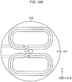
- Fig. 12A is a view illustrating one example of a first coil 111 and a first supporting member 112.
- Fig. 12B is a view illustrating one example of a second coil 113 and a second supporting member 114.
- Fig. 12A is a view corresponding to Fig. 2A
- Fig. 12B is a view corresponding to Fig. 2B .
- the number of turns of each of the first coil 111 and the second coil 113 is set to two turns, and the first coil 111 and the second coil 113 are set the same in the number of turns.
- the shape of the first coil 111 and the second coil 113 is set to a flat spiral shape.
- the flat spiral means that a water-cooled cable is wound around in a direction vertical to a shaft (center shaft 5) of the first coil 111 and the second coil 113 as illustrated in Fig. 11 , Fig. 12A , and Fig. 12B .
- the water-cooled cables forming the first coil 111 and the second coil 113 are wound around so as to be arranged in a direction vertical to the shaft (center shaft 5) of the first coil 111 and the second coil 113.
- the first coil 111 and the second coil 113 are each formed in a flat spiral shape, thereby making it possible to widen a coil width W illustrated in Fig. 11 when the first coil 111 and the second coil 113 are arranged so as to make their coil surfaces substantially parallel to each other with the intervals G provided therebetween.
- the coil width W means the length of a group of the water-cooled cables adjacent to each other in a direction vertical to the center shaft 5. As long as the intervals G are the same, as the coil width W is wider, magnetic fluxes do not easily pass through between the intervals G and magnetic reluctance becomes larger. Thus, it is possible to increase the coupling coefficient k.
- variable magnification ⁇ of the combined inductance GL when seen from the alternating-current power supply circuit (see (4) Equation).
- the variable magnification ⁇ of the combined inductance GL when seen from the alternating-current power supply circuit can be made larger.
- Fig. 13 is a view illustrating a second example of the structure of the inductance adjusting device in this embodiment.
- Fig. 13 is a view corresponding to Fig. 1A .
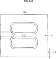
- Fig. 14A is a view illustrating one example of a first coil 131 and a first supporting member 132.
- Fig. 14B is a view illustrating one example of a second coil 133 and a second supporting member 134.
- Fig. 14A is a view corresponding to Fig. 2A
- Fig. 14B is a view corresponding to Fig. 2B .
- the number of turns of each of the first coil 131 and the second coil 133 is set to two turns, and the first coil 131 and the second coil 133 are set the same in the number of turns.
- the shape of the first coil 131 and the second coil 133 is set to a longitudinally wound shape.
- the longitudinally winding means that a water-cooled cable is wound around in a direction along a shaft (center shaft 5) of the first coil 111 and the second coil 113 as illustrated in Fig. 13 , Fig. 14A , and Fig. 14B .
- the water-cooled cables forming the first coil 131 and the second coil 133 are wound around so as to be arranged in a direction along the shaft (center shaft 5) of the first coil 131 and the second coil 133.
- the coil width W is the same as that in the case where the number of turns is one turn.
- the variable magnification ⁇ of the combined inductance GL when seen from the alternating-current power supply circuit is the same as that in the case where the number of turns is one turn, and is smaller than that in the case of the flat spiral shape.
- the combined inductance GL is proportional to the square of the number of turns.
- the number of turns is two turns.
- the number of turns is not limited to two turns, and may be three turns or more.
- the number of turns only needs to be determined according to the size of the inductance adjusting device, the variable magnification ⁇ , the magnitude of the combined inductance GL, the cost of the inductance adjusting device, or the like.
- the case where the number of turns of the first coil 111 and the first supporting member 112 and the number of turns of the first coil 131 and the first supporting member 132 are the same has been explained as an example. However, they may be different in the number of turns of these.
- a third embodiment In this embodiment, a plurality of groups of a first coil and a second coil are provided. As above, this embodiment and the first and second embodiments mainly differ in structure because the number of groups of the first coil and the second coil differs. Thus, in the explanation of this embodiment, the same reference numerals and symbols as those added to Fig. 1 to Fig. 14B are added to the same parts as those in the first and second embodiments, or the like, and their detailed explanations are omitted.
- Fig. 15A and Fig. 15B are views illustrating one example of a structure of an inductance adjusting device in this embodiment.
- Fig. 15A is a view corresponding to Fig. 11
- Fig. 15B is a view corresponding to Fig. 1B .
- Fig. 15A the case where two of the group of the first coil 111, the first supporting member 112, the second coil 113, and the second supporting member 114, which are illustrated in Fig. 11 , are provided will be explained as an example.
- the inductance adjusting device in this embodiment includes: a group of a first coil 111a, a first supporting member 112a, a second coil 113a, and a second supporting member 114a; and a group of a first coil 111b, a first supporting member 112b, a second coil 113b, and a second supporting member 114b.
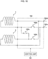
- Fig. 16A to Fig. 16D are views each illustrating one example of a connecting method of the first coil 111a, the second coil 113a, the first coil 111b, and the second coil 113b.
- Fig. 16A to Fig. 16D are views corresponding to Fig. 5A to Fig. 5B .
- Fig. 16A, Fig. 16B , and Fig. 16C each illustrate an example where the first coil 111a, the second coil 113a, the first coil 111b, and the second coil 113b are connected in series.
- Fig. 16A illustrates connection such that magnetic fluxes generated from the first coil 111a and the second coil 113a and magnetic fluxes generated from the first coil 111b and the second coil 113b are intensified mutually.
- Fig. 16B illustrates connection such that magnetic fluxes generated from the first coil 111a and the second coil 113a and magnetic fluxes generated from the first coil 111b and the second coil 113b are weakened mutually.
- Fig. 16C illustrates connection such that magnetic fluxes generated from the first coil 111a and the second coil 113a are intensified mutually and magnetic fluxes generated from the first coil 111b and the second coil 113b are weakened mutually.
- Fig. 16D illustrates an example where the first coil 111a and the second coil 113a are connected in series, the first coil 111b and the second coil 113b are connected in series, and the series-connected first coil 111a and second coil 113a and the series-connected first coil 111b and second coil 113b are connected in parallel.
- both ends of each circuit illustrated in Fig. 16A to Fig. 16B are connected to the alternating-current power supply circuit.
- the connecting method of the first coil 111a, the second coil 113a, the first coil 111b, and the second coil 113b is not limited to the ones illustrated in Fig. 16A to Fig. 16B as long as the group of the first coils and the second coils that are connected in series or parallel is connected to another group in series or parallel.
- the first coil 111a, the second coil 113a, the first coil 111b, and the second coil 113b may be connected in parallel.
- the inductance adjusting device in this embodiment includes: power feeding terminals 1507a to 1507h; and water feeding terminals 1508a to 1508h.
- the connecting method of the first coil 111a, the second coil 113a, the first coil 111b, and the second coil 113b end portions of the first coil 111a, the second coil 113a, the first coil 111b, and the second coil 113b are electrically connected to some of the power feeding terminals 1507a to 1507h.
- This embodiment is structured as above, thereby making it possible to increase the variable magnification ⁇ of the combined inductance GL when seen from the alternating-current power supply circuit.
- the number of groups of the first coil and the second coil is not limited to two groups, and may be three groups or more.
- the number of groups of the first coil and the second coil is set to N groups, it is possible to switch the variable magnification ⁇ of the combined inductance GL when seen from the alternating-current power supply circuit in a range of (L - kL) ⁇ 2N to (L + kL) ⁇ 2N.
- the self-inductances L1, L2 of the first coil and the second coil are set to L.
- the number of groups of the first coil and the second coil is increased, thereby making it possible to fabricate a more general-purpose inductance adjusting device. This leads to a reduction in cost of the inductance adjusting device.
- this embodiment can be applied to both the first embodiment and the second embodiment. Furthermore, in this embodiment as well, the various modified examples explained in the first and second embodiments can be employed.
- Fig. 17A is a view illustrating one example of a structure of first coils 171a and 171b and a first supporting member 172.
- Fig. 17B is a view illustrating one example of a structure of second coils 173a and 173b and a second supporting member 174.
- Fig. 17A is a view corresponding to Fig. 2A
- Fig. 17B is a view corresponding to Fig. 2B .
- the first coils 171a and 171b are arranged so as to make their rotation axes coaxial with the center shaft 5. Further, the first coils 171a and 171b are arranged on the same horizontal plane (X-Y plane). Further, the first coils 171a and 171b are arranged so as to maintain a state of being displaced by 90° in terms of angle in their rotation direction.
- the second coils 173a and 173b are arranged so as to make their rotation axes coaxial with the center shaft 5. Further, the second coils 173a and 173b are arranged on the same horizontal plane (X-Y plane). Further, the second coils 173a and 173b are arranged so as to maintain a state of being displaced by 90° in terms of angle in their rotation direction.
- the first coils 171a and 171b and the second coils 173a and 173b are arranged so as to make coil surfaces of the first coils 171a and 171b and coil surfaces of the second coils 173a and 173b parallel in a state of having the intervals G therebetween.
- the interval G may be constant or variable.
- holes 172a, 172b intended for attaching the first coil 171a are formed in the first supporting member 172.
- holes 172c to 172f intended for attaching the first coil 171b are formed in the first supporting member 172.
- the holes 172e, 172f are to arrange a portion of the first coil 171b overlapping with the first coil 171a on a surface opposite to the surface illustrated in Fig. 17A so as to prevent the first coils 171a and 171b from interfering with each other on the surface illustrated in Fig. 17A .
- a hole 172g intended for attaching the first supporting member 172 to the center shaft 5 is formed in the center of the first supporting member 172.
- holes 174a, 174b intended for attaching the second coil 173a are formed in the second supporting member 174.
- holes 174c to 174f intended for attaching the second coil 173b are formed in the second supporting member 174.
- the holes 174e, 174f are to arrange a portion of the second coil 173b overlapping with the second coil 173a on a surface opposite to the surface illustrated in Fig. 17B so as to prevent the second coils 173a and 173b from interfering with each other on the surface illustrated in Fig. 17B .
- a hole 174g intended for arranging the second supporting member 174 substantially coaxially with the center shaft 5 is formed in the center of the second supporting member 174.
- the hole 174g is formed so as to have an interval between the second supporting member 174 and the center shaft 5 when the center shaft 5 is passed through the hole 174g.
- the rotation angle of the first coils 1, 81, 91, 111, and 131 is set to range from 0° to 180°.
- this embodiment is structured as above, and thereby it is possible to make the variable magnification ⁇ of the combined inductance GL when seen from the alternating-current power supply circuit the same as the value of the inductance adjusting devices in the first to third embodiments even when the rotation angle of the first coils 171a, 171b is set to range from 0° to 90°.
- the range of the rotation angle of the first coils 171a, 171b is reduced as above, to thereby suppress great deformation of water-cooled cables forming the first coils 171a, 171b.
- more room for flexibility of the first coils 171a, 171b is made, thereby making it possible to improve control accuracy for rotating the first coils 171a, 171b.
- the range of the rotation angle of the first coils 171a, 171b is not limited to 0° to 90°.
- the rotation angle of the first coils 171a, 171b may range from 0° to 180° .
- first coils and second coils to be arranged in a direction vertical to the center shaft 5 are two each, which are the first coils 171a, 171b and the second coils 173a, 173b, has been explained as an example.
- the number of first coils and second coils to be arranged in a direction vertical to the center shaft 5 may be three or more each.
- the number of first coils and second coils to be arranged in a direction vertical to the center shaft 5 is set to N (N is an integer of 2 or more) and the first coils are arranged so as to maintain a state of being displaced by 90/(N/2)° in terms of angle in their rotation direction, thereby making it possible to set the range of the rotation angle of the first coil to 0° to 180/N°.
- this embodiment can be applied to any of the first to third embodiments. Furthermore, in this embodiment as well, the various modified examples explained in the first to third embodiments can be employed.
- Fig. 18 is a view illustrating one example of a structure for switching of the connection between the first coil 1 and the second coil 3.
- an inductance adjusting device in this embodiment further includes a control unit 181 and a contact point switch 182 in the inductance adjusting device explained in the first embodiment.
- the control unit 181 and the contact point switch 182 are used, to thereby structure a switching device that automatically changes the connection between the first coil and the second coil.
- the contact point switch 182 has contact points 182a to 182c.
- the control unit 181 outputs a switching instruction signal to the contact point switch 182.
- the switching instruction signal information indicating whether to open or close each of the contact points 182a to 182c is contained.
- the contact point switch 182 opens or closes the contact points 182a to 182c according to the information contained in the switching instruction signal output from the control unit 181.
- the contact points 182a, 182b are opened and the contact point 182c is closed
- the first coil 1 and the second coil 3 are connected in series.
- the contact points 182a, 182b are closed and the contact point 182c is opened, the first coil 1 and the second coil 3 are connected in parallel.
- Fig. 18 illustrates the state where the first coil 1 and the second coil 3 are connected in series.
- the switching instruction signal may be generated based on an instruction given by an operator to the control unit 181 to be transmitted to the contact point switch 182, or may be generated based on a preset schedule to be transmitted to the contact point switch 182. Further, the switching instruction signal may also be generated by another method.
- output ends 182d, 182e of the contact point switch 182 and power feeding terminals are electrically connected to each other.
- the output ends 182d, 182e of the contact point switch 182 and some of the power feeding terminals 7a to 7d illustrated in Fig. 1 only need to be electrically connected to each other.
- the number of power feeding terminals does not need to be four, and two power feeding terminals are sufficient.
- This embodiment is structured as above, thereby making it possible to switch the variable magnification ⁇ of the combined inductance GL when seen from the alternating-current power supply circuit in the range of (L - kL) ⁇ 2 to (L + kL) ⁇ 2.
- the self-inductances L1, L2 of the first coil 1 and the second coil 3 are set to L.
- the connection between the first coil 1 and the second coil 3 is switched to the parallel connection from the series connection, and is switched to the series connection from the parallel connection, thereby making it possible to increase the variable magnification ⁇ of the combined inductance GL when seen from the alternating-current power supply circuit as compared to the first embodiment.
- This embodiment can be applied to any of the first to fourth embodiments. Further, it is possible to switch the connection between the coils to either the series connection or the parallel connection in a unit of a single coil (the first coil, the second coil). For example, in the case where there are two first coils and two second coils, it is possible to connect the two first coils in series or parallel, connect the two second coils in series or parallel, and connect the series-connected or parallel-connected two first coils and the series-connected or parallel-connected two second coils in series or parallel.
- the inductance adjusting device is connected in parallel with the heating coil, it is necessary to increase the inductance of the inductance adjusting device to about 10 times the inductance of the heating coil, for example, in order to reduce the current to flow through the inductance adjusting device. Therefore, losses of the coil and the magnetic body structuring the inductance adjusting device increase.
- an inductance adjusting device in this embodiment further includes a capacitor to be connected in series to the first coil and the second coil in the structure of the inductance adjusting device in each of the first to fifth embodiments.
- the inductance adjusting device in this embodiment further includes a control unit that performs control for performing the rotation of at least one of the first coil and the second coil in the structure of the inductance adjusting device in each of the first to fifth embodiments.
- the inductance adjusting device in this embodiment becomes one in which the voltage drop compensating capacitor and the control unit are added to the inductance adjusting device in each of the first to fifth embodiments.
- the same reference numerals and symbols as those added to Fig. 1 to Fig. 18 are added to the same parts as those in the first to fifth embodiments, or the like, and their detailed explanations are omitted.
- connecting the inductance adjusting device to the inductive load in series with respect to the resonant current means that the inductance adjusting device is electrically connected to the resonant circuit, and thereby the inductance adjusting device is connected to the resonant circuit so as to prevent the resonant current from branching.
- Fig. 19A to Fig. 19D are views illustrating connection examples of the inductance adjusting device.
- the inductance adjusting device is connected to an induction heating device will be explained as an example.
- the induction heating device by an eddy current generated when a magnetic field generated by application of an alternating current to a heating coil penetrates a metal plate such as a steel plate, the metal plate is inductively heated.
- the first coil and the second coil mutually electrically connected are illustrated as a coil 191a summarily for convenience of illustration.
- One end of the coil 191a is electrically connected to one end of a voltage drop compensating capacitor 191b.
- the voltage drop compensating capacitor 191b is electrically connected to the first coil and the second coil.
- the other end of the coil 191a and the other end of the voltage drop compensating capacitor 191b are connected to the outside of the inductance adjusting device.
- the other end of the coil 191a and the other end of the voltage drop compensating capacitor 191b are electrically connected to some of the power feeding terminals 7a to 7d.
- an inductance adjusting device 191 is connected to an induction heating device including the current-type inverter 192a, a transformer 193, a resonant capacitor 194, and a heating coil 195.
- the resonant capacitor 194 and the heating coil 195 are connected in parallel, and the inductance adjusting device 191 is connected between the resonant capacitor 194 and the heating coil 195.
- a large current generated in parallel resonance flows through the heating coil 195, and thereby the induction heating is performed.
- a resonant current I flows through a path circulating through the inductance adjusting device 191, the resonant capacitor 194, and the heating coil 195.
- the inductance adjusting device 191 is connected to an induction heating device including the voltage-type inverter 192b, the transformer 193, resonant capacitors 196a, 196b, and the heating coil 195.
- the resonant capacitors 196a, 196b and the heating coil 195 are connected in series, and the inductance adjusting device 191 is connected between the resonant capacitor 196a and the heating coil 195.
- a large current generated in series resonance flows through the heating coil 195, and thereby the induction heating is performed.
- the resonant current I flows through a path circulating through the inductance adjusting device 191, the resonant capacitor 196a, (a secondary winding of) the transformer 193, the resonant capacitor 196b, and the heating coil 195.
- the inductance of the coil 191a is the aforementioned combined inductance GL.
- an electrostatic capacitance of the resonant capacitor 194 and a combined electrostatic capacitance of the resonant capacitors 196a, 196b are each set to C2
- an electrostatic capacitance of the voltage drop compensating capacitor 191b is set to C1
- an inductance of the heating coil 195 is set to LL.
- a combined inductance LT of the inductance of the coil 191a (namely, the combined inductance GL) and the inductance LL of the heating coil 195 is expressed by (6) Equation below.
- a combined electrostatic capacitance CT of the electrostatic capacitance C2 of the resonant capacitor 194 or the combined electrostatic capacitance C2 of the resonant capacitors 196a, 196b and the electrostatic capacitance C1 of the voltage drop compensating capacitor 191b is expressed by (7) Equation below.
- a resonance frequency f is expressed by (8) Equation below.
- the inductance adjusting device 191 is connected to an induction heating device including the current-type inverter 192a, the transformer 193, and the heating coil 195.
- the inductance adjusting device 191 and the heating coil 195 are connected in parallel.
- a large current generated in parallel resonance flows through the heating coil 195, and thereby the induction heating is performed.
- the resonant current I flows through a path circulating through the inductance adjusting device 191 and the heating coil 195.
- the inductance adjusting device 191 is connected to an induction heating device including the v ⁇ ltage-type inverter 192b, the transformer 193, and the heating coil 195.
- the inductance adjusting device 191 and the heating coil 195 are connected in series.
- a large current generated in series resonance flows through the heating coil 195, and thereby the induction heating is performed.
- the resonant current I flows through a path circulating through the inductance adjusting device 191, the heating coil 195, and (the secondary winding of) the transformer 193.
- the combined inductance LT of the inductance of the coil 191a (namely, the combined inductance GL) and the inductance LL of the heating coil 195 is expressed by (6) Equation described previously.
- the electrostatic capacitance C1 of the voltage drop compensating capacitor can be selected according to (10) Equation below so as to be able to compensate for a delay of the combined inductance GL of the inductance adjusting device 191.
- C 1 1 / 2 ⁇ f 2 ⁇ GL
- a representative value of the combined inductance GL in the inductance adjusting device 191 is employed.
- the representative value of the combined inductance GL in the inductance adjusting device 191 is the value of 1/2 (namely, the average value) of the variable range (the maximum value and the minimum value) of the combined inductance GL in the inductance adjusting device 191, for example.
- f in (10) Equation is the resonance frequency.
- the voltage drop compensating capacitor 191b is connected to the load side of the coil 191 in series.
- This embodiment is structured in this manner, to thereby compensate for the drop amount of the voltage of the inductance adjusting device 191 by the lagging current.
- the applied voltage to the inductance adjusting device 191 decreases and it becomes unnecessary to perform the high-voltage measures for the inductance adjusting device 191.
- the control unit 197 monitors the value of the inductance of the heating coil 195.
- the control unit 197 changes the combined inductance GL in the inductance adjusting device 191 according to the value of the inductance of the heating coil 195.
- Changing the combined inductance GL in the inductance adjusting device 191 is performed by rotating at least one of the first coil and the second coil.
- the control unit 197 changes the combined inductance GL in the inductance adjusting device 191 so that the frequency of the current flowing through the heating coil 195 becomes the resonance frequency f. In this manner, the electric circuit including the heating coil 195 becomes the resonant circuit.
- the method of determining the rotation angle of at least one of the first coil and the second coil is as follows, for example. First, the relationship between the rotation angle of at least one of the first coil and the second coil and the combined inductance GL in the inductance adjusting device 191 is examined beforehand. The control unit 197 stores information indicating this relationship. The control unit 197 calculates, according to the value of the inductance of the heating coil 195, the value of the combined inductance GL in the inductance adjusting device 191 in order for the frequency of the current flowing through the heating coil 195 to be the resonance frequency f. Then, the control unit 197 derives the rotation angle corresponding to the calculated value from the aforementioned relationship.
- the inductance adjusting device in the first embodiment was used.
- the shapes of the first circumferential portion 1a, the second circumferential portion 1b, the third circumferential portion 3a, and the fourth circumferential portion 3b are the shapes illustrated in Fig. 2A and Fig. 2B .
- the length in the long side direction was set to 300 mm and the length in the short side direction was set to 150 mm.
- an inductance adjusting device to be a comparative example of the example 1 a solenoid coil with three turns was fabricated by a water-cooled copper pipe, and one made by arranging a magnetic core in this solenoid coil as described in Patent Literature 1 was fabricated. In a state of an alternating current of 1500 A and 35 kHz applied to this solenoid coil, an occupancy ratio of the magnetic core to the solenoid coil was changed, and the inductance of the inductance adjusting device and the power loss of the inductance adjusting device were measured. Results thereof are illustrated below.
- the example 1 and the comparative example 1 were substantially equal in the variable magnification ⁇ of the combined inductance GL when seen from the alternating-current power supply circuit, but in the comparative example 1, the power loss W became about 30 times of the example 1.
- the inductance adjusting device in the first example of the second embodiment was used.
- the shapes of the first circumferential portion, the second circumferential portion, the third circumferential portion, and the fourth circumferential portion are the shapes illustrated in Fig. 12A and Fig. 12B .
- the length in the long side direction was set to 300 mm and the length in the short side direction was set to 150 mm.
- the number of turns of each of the first coil 111 and the second coil 113 was set to two turns.
- the combined inductance GL in the case where the rotation angle of the first coil 111 in a state where an alternating current of 1500 A and 35 kHz is applied to the first coil 111 and the second coil 113 and magnetic fluxes generated from the first coil 111 and the second coil 113 are most weakened each other was set to 0° and the first coil 111 was rotated by 30° pitch in the range of 0° to 180° and the power loss of the inductance adjusting device were measured. Results thereof are illustrated below.
- variable magnification ⁇ of the combined inductance GL when seen from the alternating-current power supply circuit increased, and in this example as well, as compared to the comparative example 1, it was possible to drastically reduce the power loss.
- the inductance adjusting device in the second example of the second embodiment was used.
- the shapes of the first circumferential portion, the second circumferential portion, the third circumferential portion, and the fourth circumferential portion are the shapes illustrated in Fig. 13 , Fig. 14A , and Fig. 14B .
- the length in the long side direction was set to 300 mm and the length in the short side direction was set to 150 mm.
- the number of turns of each of the first coil 131 and the second coil 133 was set to two turns.
- the combined inductance GL in the case where the rotation angle of the first coil 131 in a state where an alternating current of 1500 A and 35 kHz is applied to the first coil 131 and the second coil 133 and magnetic fluxes generated from the first coil 131 and the second coil 133 are most weakened each other was set to 0° and the first coil 131 was rotated by 30° pitch in the range of 0° to 180° and the power loss of the inductance adjusting device were measured. Results thereof are illustrated below.
- the first coil 131 and the second coil 133 each having the longitudinally wound shape were used, and thus as compared to the example 2, the variable magnification ⁇ of the combined inductance GL when seen from the alternating-current power supply circuit decreases, but the value is at a problem-free level practically. Further, as compared to the comparative example 1, it was possible to drastically reduce the power loss.
- the combined inductance GL and the power loss of the inductance adjusting device were measured under the same condition as that of the example 2 except that the first coil 111 and the second coil 113 were connected in parallel. Results thereof are illustrated below.
- the variable magnification ⁇ of the combined inductance GL when seen from the alternating-current power supply circuit increased. Further, in this example as well, as compared to the comparative example 1, it was possible to drastically reduce the power loss. Further, a comparison between this example and the example 2 reveals that they were the same in the variable magnification ⁇ of the combined inductance GL when seen from the alternating-current power supply circuit, but in this example, the magnitude of the combined inductance GL became 1/4 of that of the example 2.
- the inductance adjusting device is structured like the fifth embodiment and the connection between the first coil 111 and the second coil 113 is switched, thereby making it possible to widen the range of the combined inductance GL.
- the present invention can be utilized for an electric circuit including an inductive load, and so on.
Landscapes
- Engineering & Computer Science (AREA)
- Power Engineering (AREA)
- Physics & Mathematics (AREA)
- Electromagnetism (AREA)
- Coils Or Transformers For Communication (AREA)
- Magnetic Resonance Imaging Apparatus (AREA)
Abstract
Description
- The present invention relates to an inductance adjusting device, and is suitable when used for adjusting an inductance of an electric circuit, in particular.
- The needs for reducing the emission of greenhouse effect gas such as carbon dioxide have been high up to now in order to prevent global warming. For example, in the field of steel, operating an induction heating device intended for performing hardening at high frequencies with high efficiency has been achieved. Further, the introduction of induction heating devices as an alternative technique to a gas heating furnace whose heating efficiency is poor has been increasing recently. Further, in the field of automobiles, the development of a technique to feed power to an electric vehicle in a non-contact manner has been in progress.
- These techniques are a technique in which a capacitor (electrostatic capacitance C) and a load coil (inductance L) are connected in series or parallel to a high frequency generating device to generate voltage resonance or current resonance. In these techniques, it is possible to heat an object to be heated in a non-contact manner by magnetic fluxes generated when a resonant current flows through the load coil. Further, in these techniques, it is possible to feed power in a non-contact manner by utilizing an electromagnetic induction phenomenon based on the magnetic fluxes generated when the resonant current flows through the load coil. Incidentally, the resonant current indicates a current whose frequency is a resonance frequency.
- In the case of utilizing a resonance phenomenon as above, the capacitor (electrostatic capacitance C) and a heating coil (the inductance L) are determined, and thereby the frequency (resonance frequency) in the high frequency generating device is determined unambiguously. Therefore, when the actual frequency deviates from a target frequency at start-up of the device, it is necessary to adjust a reactance. As a means for it, a means that adjusts the electrostatic capacitance C of a circuit has been employed up to now in order to obtain the target frequency.
- Concretely, a method has been considered in which a previously-prepared capacitor for fine adjustment is connected to or disconnected from the circuit including the capacitor and the load coil, to thereby adjust the electrostatic capacitance C of the circuit. However, this method requires installation of the capacitor for fine adjustment additionally. Therefore, the device becomes expensive. Further, in the case of switching the frequency during operation, it is necessary to cut the power supply once, automatically switch a power feeding terminal of the capacitor for fine adjustment remotely, turn on the power again, and continue the operation. In this case, a terminal switch that enables remote manipulation is required. Therefore, the device becomes expensive. Further, it is not technically easy to continuously vary the electrostatic capacitance C of the circuit under the large current.
- Therefore, adjustment of the inductance L of the circuit is considered. As a technique of adjusting the inductance L of the circuit, there are techniques described in
Patent Literatures 1 to 3 below. - In
Patent Literature 1, there has been disclosed a method of adjusting the inductance L by moving a magnetic core in a solenoid coil as a technique relating to induction heating. In the technique described inPatent Literature 1 concretely, the inductance L is adjusted by moving the magnetic core having high relative permeability in the solenoid coil, to thereby change an occupancy ratio of the magnetic core in the solenoid coil. - In
Patent Literature 2, there has been disclosed a method of adjusting the inductance L by extending and contracting a solenoid coil without using a magnetic core as a technique relating to non-contact power feeding. - In
Patent Literature 3, there has been disclosed a method of adjusting the inductance L by changing relative positions between two coils as a technique relating to a high-frequency electronic circuit to be used on a substrate. Concretely, in the technique described inPatent Literature 3, two coils having the same shape are used. The gap between the two coils is changed, or the two coils are rotated about ends of the coils made as a shaft or opened/closed, and thereby a rotation angle or opening/closing angle of the two coils is changed. -
- Patent Literature 1: Japanese Laid-open Patent Publication No.
2004-30965 - Patent Literature 2: Japanese Laid-open Patent Publication No.
2016-9790 - Patent Literature 3: Japanese Laid-open Patent Publication No.
58-147107 - However, in the technique described in
Patent Literature 1, the magnetic core is inserted in the solenoid coil. Therefore, when a larger current is applied to the solenoid coil, magnetic fluxes generated from the solenoid coil concentrate on the magnetic core. Thus, in the technique described inPatent Literature 1, the loss of the magnetic core (core loss or hysteresis loss) increases. Further, in the technique described inPatent Literature 1, by the magnetic fluxes concentrating on ends of the magnetic core, the solenoid coil is inductively heated. Accordingly, in the technique described inPatent Literature 1, it is not easy to improve the heating efficiency. - Further, in the technique described in
Patent Literature 2, the inductance L is adjusted by extending and contracting the solenoid coil. Therefore, it is necessary to increase the amount of extension and contraction of the solenoid coil according to a variable magnification of the inductance L. Thus, in the technique described inPatent Literature 2, the entire device increases. Further, in the technique described inPatent Literature 2, a support structure that supports deformation of the coil becomes complicated. Incidentally, the variable magnification of the inductance L is a value obtained by dividing the maximum value of the inductance L by the minimum value of the inductance L. - Further, since the technique described in
Patent Literature 3 is the technique relating to the high-frequency electronic circuit to be used on a substrate, it is not easy to apply a large current to the high-frequency electronic circuit. Further, even if a state where a large current is allowed to be applied to the high-frequency electronic circuit is made, in the technique described inPatent Literature 3, the ends of the coils serve as a shaft, and the rotation angle or opening/closing angle is changed. When a large current of several hundred to several thousand amperes is applied like the case of performing the induction heating, excessive repulsive force and attractive force occur between the two coils. In the technique described inPatent Literature 3, due to the structure in which the ends of the coils serve as a shaft, the previously-described repulsive force and attractive force occur, resulting in that it is not easy to accurately adjust the inductance L. Furthermore, in the technique described inPatent Literature 3, there is a possibility that the inductance adjusting device is broken because the previously-described repulsive force and attractive force occur. Thus, in the technique described inPatent Literature 3, it is necessary to employ a special structure in order to apply a large current. Further, in the technique described inPatent Literature 3, the change in the inductance L is proportional to the gap or a logarithm of the angle. Therefore, in the technique described inPatent Literature 3, the relationship between the gap or rotation angle of the two coils and the inductance L largely deviates from the linear relationship. Therefore, in the technique described inPatent Literature 3, it is not easy to control the frequency with high accuracy. - The present invention has been made in consideration of the above-described problems, and an object thereof is to enable an inductance of an electric circuit to be adjusted accurately with a simple and compact structure.
- The inductance adjusting device of the present invention is an inductance adjusting device that adjusts an inductance of an electric circuit, the inductance adjusting device including: a first coil having a first circumferential portion, a second circumferential portion, and a first connecting portion; and a second coil having a third circumferential portion, a fourth circumferential portion, and a second connecting portion, in which the first circumferential portion, the second circumferential portion, the third circumferential portion, and the fourth circumferential portion each are a portion circling so as to surround an inner region thereof, the first connecting portion is a portion that connects one end of the first circumferential portion and one end of the second circumferential portion mutually, the second connecting portion is a portion that connects one end of the third circumferential portion and one end of the fourth circumferential portion mutually, the first coil and the second coil are connected in series or parallel, the first circumferential portion and the second circumferential portion exist on the same plane, the third circumferential portion and the fourth circumferential portion exist on the same plane, a set of the first circumferential portion and the second circumferential portion and a set of the third circumferential portion and the fourth circumferential portion are arranged in a parallel state with an interval provided therebetween, at least one of the first coil and the second coil rotates about a shaft of the first coil and the second coil as a rotation shaft, the shaft is a shaft passing through a middle position between the center of the first circumferential portion and the center of the second circumferential portion and a middle position between the center of the third circumferential portion and the center of the fourth circumferential portion, the first circumferential portion and the second circumferential portion are arranged so as to maintain a state where at least one of the first coil and the second coil is displaced by 180° in terms of angle in a rotation direction, and the third circumferential portion and the fourth circumferential portion are arranged so as to maintain a state where at least one of the first coil and the second coil is displaced by 180° in terms of angle in the rotation direction.
-
-
Fig. 1A is a view illustrating a first example of a structure of an inductance adjusting device. -
Fig. 1B is a view illustrating one example of an appearance of a surface where power feeding terminals of the inductance adjusting device inFig. 1A are arranged. -
Fig. 2A is a view illustrating a first example of a first coil and a first supporting member. -
Fig. 2B is a view illustrating a first example of a second coil and a second supporting member. -
Fig. 3A is a view illustrating the first coil in a certain state and the first coil in a state of being rotated by 180° about a center shaft as a rotation shaft from the certain state in an overlapping manner. -
Fig. 3B is a view illustrating the second coil in a certain state and the second coil in a state of being rotated by 180° about the center shaft as a rotation shaft from the certain state in an overlapping manner. -
Fig. 4 is a view illustrating one example of the positional relationship between the first coil and the second coil. -
Fig. 5A is a view illustrating a first example of directions of magnetic fluxes generated in the first coil and the second coil, together with circuit symbols of the first coil and the second coil. -
Fig. 5B is a view illustrating a second example of the directions of the magnetic fluxes generated in the first coil and the second coil, together with the circuit symbols of the first coil and the second coil. -
Fig. 6A is a view illustrating the first example of the magnetic fluxes generated in the first coil and the second coil, together with the first coil and the second coil in a state of being arranged in the inductance adjusting device. -
Fig. 6B is a view illustrating the second example of the magnetic fluxes generated in the first coil and the second coil, together with the first coil and the second coil in a state of being arranged in the inductance adjusting device. -
Fig. 7A is a view illustrating one example of the relationship between an inductance and a rotation angle in the inductance adjusting device in this embodiment. -
Fig. 7B is a view illustrating one example of the relationship between an inductance and a rotation angle in the technique described inPatent Literature 3. -
Fig. 8A is a view illustrating a first modified example of the first coil and the first supporting member. -
Fig. 8B is a view illustrating a first modified example of the second coil and the second supporting member. -
Fig. 9A is a view illustrating a second modified example of the first coil and the first supporting member. -
Fig. 9B is a view illustrating a second modified example of the second coil and the second supporting member. -
Fig. 10 is a view illustrating a modified example of the structure of the inductance adjusting device. -
Fig. 11 is a view illustrating a second example of the structure of the inductance adjusting device. -
Fig. 12A is a view illustrating a second example of the first coil and the first supporting member. -
Fig. 12B is a view illustrating a second example of the second coil and the second supporting member. -
Fig. 13 is a view illustrating a third example of the structure of the inductance adjusting device. -
Fig. 14A is a view illustrating a third example of the first coil and the first supporting member. -
Fig. 14B is a view illustrating a third example of the second coil and the second supporting member. -
Fig. 15A is a view illustrating a fourth example of the structure of the inductance adjusting device. -
Fig. 15B is a view illustrating one example of an appearance of a surface where power feeding terminals of the inductance adjusting device inFig. 15A are arranged. -
Fig. 16A is a view illustrating a first example of a connecting method of the first coil, the second coil, the first coil, and the second coil. -
Fig. 16B is a view illustrating a second example of the connecting method of the first coil, the second coil, the first coil, and the second coil. -
Fig. 16C is a view illustrating a third example of the connecting method of the first coil, the second coil, the first coil, and the second coil. -
Fig. 16D is a view illustrating a fourth example of the connecting method of the first coil, the second coil, the first coil, and the second coil. -
Fig. 17A is a view illustrating a fifth example of the first coil and the first supporting member. -
Fig. 17B is a view illustrating a fifth example of the second coil and the second supporting member. -
Fig. 18 is a view illustrating one example of a structure for switching of connection between the first coil and the second coil. -
Fig. 19A is a view illustrating a first example of an electric circuit to which the inductance adjusting device is applied. -
Fig. 19B is a view illustrating a second example of the electric circuit to which the inductance adjusting device is applied. -
Fig. 19C is a view illustrating a third example of the electric circuit to which the inductance adjusting device is applied. -
Fig. 19D is a view illustrating a fourth example of the electric circuit to which the inductance adjusting device is applied. - Hereinafter, there will be explained embodiments of the present invention with reference to the drawings.
- First, a first embodiment will be explained.
-
Fig. 1A and Fig. 1B are views each illustrating one example of a structure of an inductance adjusting device in this embodiment. Incidentally, X, Y, and Z coordinates illustrated in each drawing indicate the relationship of directions in each drawing. The mark of ● added inside ○ indicates the direction from the far side of the sheet toward the near side. The mark of × added inside ○ indicates the direction from the near side of the sheet toward the far side. -
Fig. 1A is a view illustrating one example of the structure of the inductance adjusting device in this embodiment.Fig. 1B is a view illustrating one example of an appearance of a surface wherepower feeding terminals 7a to 7d of the inductance adjusting device inFig. 1A are arranged. - The inductance adjusting device includes: a
first coil 1, a first supportingmember 2, asecond coil 3, a second supportingmember 4, acenter shaft 5, adrive unit 6, thepower feeding terminals 7a to 7d,water feeding terminals 8a to 8d, and acasing 9. InFig. 1A , the inside of thecasing 9 is illustrated fluoroscopically. Incidentally, the inductance adjusting device in this embodiment does not include a core for adjusting an inductance. -
Fig. 2A is a view illustrating one example of thefirst coil 1 and the first supportingmember 2.Fig. 2B is a view illustrating one example of thesecond coil 3 and the second supportingmember 4.Fig. 3A is a view illustrating thefirst coil 1 in a certain state and thefirst coil 1 in a state of being rotated by 180° about thecenter shaft 5 as a rotation shaft from the certain state in an overlapping manner. InFig. 3A , for convenience of illustration, one of these twofirst coils 1 is illustrated by a solid line, and the other of them is illustrated by a dotted line.Fig. 3B is a view illustrating thesecond coil 3 in a certain state and thesecond coil 3 in a state of being rotated by 180° about thecenter shaft 5 as a rotation shaft from the certain state in an overlapping manner. InFig. 3B as well, similarly toFig. 3A , for convenience of illustration, one of these twosecond coils 3 is illustrated by a solid line, and the other of them is illustrated by a dotted line. Incidentally, thesecond coil 3 does not rotate as will be described later, but inFig. 3B , thesecond coil 3 is assumed to rotate. -
Fig. 2A andFig. 3A each are a view where a surface of the first supportingmember 2 facing the second supportingmember 4 is seen along the Z axis inFig. 1A .Fig. 2B andFig. 3B each are a view where a surface of the second supportingmember 4 facing the first supportingmember 2 is seen along the Z axis inFig. 1A . Incidentally, inFig. 2A andFig. 2B , the arrow lines illustrated in thefirst coil 1 and thesecond coil 3 are directions of alternating currents at the same time. The directions of the alternating currents flowing through thefirst coil 1 and thesecond coil 3 will be described later with reference toFig. 4 . - First, the
first coil 1 and the first supportingmember 2 will be explained. - The first supporting
member 2 is a member for supporting thefirst coil 1. Thefirst coil 1 is attached to the first supportingmember 2 to be fixed on the first supportingmember 2. As illustrated inFig. 2A , in the first supportingmember 2,holes first coil 1 are formed. - As illustrated in
Fig. 2A , the planar shape of the first supportingmember 2 is circular. The first supportingmember 2 is formed of an insulating and non-magnetic material that has strength capable of supporting thefirst coil 1 so as to prevent the position of thefirst coil 1 in the Z-axis direction from changing. The first supportingmember 2 is formed by using a thermosetting resin, for example. - As illustrated in
Fig. 2A , in the center of the first supportingmember 2, ahole 2c intended for attaching the first supportingmember 2 to thecenter shaft 5 is formed. Thecenter shaft 5 is passed through thehole 2c, and thereby the first supportingmember 2 is attached (fixed) to thecenter shaft 5 so as to be coaxial with thecenter shaft 5, and rotates with rotation of thecenter shaft 5. Thefirst coil 1 is supported by the first supportingmember 2.
That is, thefirst coil 1 is fixed on the first supportingmember 2. Therefore, thefirst coil 1 rotates with rotation of the first supportingmember 2. As above, thefirst coil 1 is arranged so as to make a rotation axis thereof coaxial with thecenter shaft 5. - In
Fig. 2A , thefirst coil 1 has a firstcircumferential portion 1a, a secondcircumferential portion 1b, a first connectingportion 1c, a first lead-out portion Id, and a second lead-outportion 1e. The firstcircumferential portion 1a, the secondcircumferential portion 1b, the first connectingportion 1c, the first lead-outportion 1d, and the second lead-outportion 1e are integrated. - In this embodiment, the number of turns of the
first coil 1 is one [turn]. Further, in this embodiment, the case where the figure of 8 in Arabic numerals is formed by the firstcircumferential portion 1a, the secondcircumferential portion 1b, and the first connectingportion 1c will be explained as an example. Incidentally, inFig. 3A , for convenience of illustration, illustrations of the first lead-outportion 1d and the second lead-outportion 1e are omitted. Further, inFig. 3A , the reference numeral is added to each of thefirst coils 1 illustrated in an overlapping manner. - The first
circumferential portion 1a is a portion circling so as to surround an inner region thereof. The secondcircumferential portion 1b is also a portion circling so as to surround an inner region thereof. The firstcircumferential portion 1a and the secondcircumferential portion 1b are arranged on the same horizontal plane (X-Y plane). - The first connecting
portion 1c is a portion that connects afirst end 1f of the firstcircumferential portion 1a and afirst end 1g of the secondcircumferential portion 1b mutually, and is a non-circumferential portion. - The first lead-out
portion 1d is connected to asecond end 1h of the firstcircumferential portion 1a. Thesecond end 1h of the firstcircumferential portion 1a is positioned at thehole 2b. The second lead-outportion 1e is connected to asecond end 1i of the secondcircumferential portion 1b. Thesecond end 1i of the secondcircumferential portion 1b is positioned at thehole 2a. - The first lead-out
portion 1d and the second lead-outportion 1e each become a lead-out wire for connecting thefirst coil 1 to an external part. InFig. 2A , the first lead-outportion 1d and the second lead-outportion 1e are each illustrated by a dotted line, to thereby indicate that the first lead-outportion 1d and the second lead-outportion 1e exist on a surface opposite to the surface of the first supportingmember 2 illustrated inFig. 2A . - In
Fig. 3A , thefirst coil 1 is brought into a state illustrated by a dotted line from a state illustrated by a solid line when being rotated about thecenter shaft 5 as a rotation shaft by 180° . - The
center shaft 5 is arranged in thehole 2c. Thus, thecenter shaft 5 is arranged at a position including the middle position between thecenter 1j of the firstcircumferential portion 1a and thecenter 1k of the secondcircumferential portion 1b. The firstcircumferential portion 1a and the secondcircumferential portion 1b are positioned on the sides opposite to each other across thehole 2c (center shaft 5). That is, the firstcircumferential portion 1a and the secondcircumferential portion 1b are arranged so as to maintain a state where thefirst coil 1 is displaced by 180° in terms of angle in its rotation direction. This angle is an angle formed by a virtual straight line mutually connecting the center of thehole 2c (shaft core of the center shaft 5) and thecenter 1j of the firstcircumferential portion 1a by the most direct way and a virtual straight line mutually connecting the center of thehole 2c (shaft core of the center shaft 5) and thecenter 1k of the secondcircumferential portion 1b by the most direct way. Incidentally, inFig. 3A , thecenter 1j of the firstcircumferential portion 1a and thecenter 1k of the secondcircumferential portion 1b are points illustrated virtually, and are not existent points. - The first
circumferential portion 1a, the secondcircumferential portion 1b, a thirdcircumferential portion 3a, and a fourthcircumferential portion 3b are most preferred to be the same completely in shape and size. However, as illustrated inFig. 2A andFig. 2B , it is sometimes impossible to make the firstcircumferential portion 1a, the secondcircumferential portion 1b, the thirdcircumferential portion 3a, and the fourthcircumferential portion 3b the same completely in shape and size. - Unless the state of magnetic fluxes penetrating the inside of each of the first
circumferential portion 1a, the secondcircumferential portion 1b, the thirdcircumferential portion 3a, and the fourthcircumferential portion 3b greatly differs from that in the case where the firstcircumferential portion 1a, the secondcircumferential portion 1b, the thirdcircumferential portion 3a, and the fourthcircumferential portion 3b are the same completely in shape and size when the alternating current is applied to thefirst coil 1 and thesecond coil 3, the firstcircumferential portion 1a, the secondcircumferential portion 1b, the thirdcircumferential portion 3a, and the fourthcircumferential portion 3b do not need to be the same completely in shape and size. - The present inventors changed, of various inductance adjusting devices including inductance adjusting devices in first to fifth embodiments, the sizes of the first coil and the second coil, the gap (interval in the Z-axis direction) between the first coil and the second coil, the shapes of the first coil and the second coil, and so on, to then measure variable magnifications β. However, the first circumferential portion, the second circumferential portion, the third circumferential portion, and the fourth circumferential portion were set the same completely in shape and size. As a result, the variable magnification β ranged from about 2.3 to 5.6 magnifications. A coupling coefficient k corresponding to this range ranges from about 0.4 to 0.7. Incidentally, the coupling coefficient k is expressed by (2) Equation to be described later. Thus, as a value of a standard coupling coefficient ks between the first coil and the second coil, an average value in this range (= 0.55 (= (0.4 + 0.7) ÷ 2)) is employed. This standard coupling coefficient ks becomes a representative value of the coupling coefficient in the case where the first circumferential portion, the second circumferential portion, the third circumferential portion, and the fourth circumferential portion are the same completely in shape and size.
- Here, a minimum value β min of the variable magnification β of a combined inductance GL when seen from an alternating-current power supply circuit is assumed to be 2.0. The variable magnification β of the combined inductance GL when seen from the alternating-current power supply circuit is expressed by (4) Equation to be described later. When the minimum value β min of the variable magnification β (= 2.0) is substituted in (4) Equation, a minimum value kmin of the coupling coefficient between the first coil and the second coil becomes about 0.33. When the minimum value kmin of the coupling coefficient (= 0.33) is divided by the standard coupling coefficient ks (= 0.55), 0.6 (= 0.33/0.55) is found. That is, 0.33 is required as the minimum value kmin of the coupling coefficient in order to secure the minimum value β min of the variable magnification β (= 2.0). In order to achieve 0.33 as the minimum value kmin of the coupling coefficient, the shapes and the sizes of the first circumferential portion, the second circumferential portion, the third circumferential portion, and the fourth circumferential portion only need to be the same in a portion of 60% of the total length of these. Further, the minimum value β min of the variable magnification β is preferred to be 2,5 and more preferred to be 3.0 practically. In order to correspond to this, from the result of the calculation similar to that described previously, the shapes and the sizes of the first circumferential portion, the second circumferential portion, the third circumferential portion, and the fourth circumferential portion are preferred to be the same in a portion of 78% of the total length of these, and more preferred to be the same in a region of 91% or more.
- From the above-described viewpoints, as long as the shapes and the sizes of the first
circumferential portion 1a, the secondcircumferential portion 1b, the thirdcircumferential portion 3a, and the fourthcircumferential portion 3b are the same in a portion of 60% or more of the total length of these, it is possible to regard the firstcircumferential portion 1a, the secondcircumferential portion 1b, the thirdcircumferential portion 3a, and the fourthcircumferential portion 3b as being the same in shape and size. However, in the above explanation, 60% is preferred to be 78%, and more preferred to be 91% according to the minimum value β min of the variable magnification β. - From the above, regarding the shapes and the sizes of the first
circumferential portion 1a and the secondcircumferential portion 1b, the following can be said. - When the
first coil 1 rotates about thecenter shaft 5 as a rotation shaft by 180° , a portion having a length of 60% or more of the entire length of the firstcircumferential portion 1a overlaps with a region where the secondcircumferential portion 1b existed before the aforementioned rotation. The entire length of the firstcircumferential portion 1a is a length from the first end If to thesecond end 1h of the firstcircumferential portion 1a. - In
Fig. 3A , when it is set that the state illustrated by the solid line is brought into the state illustrated by the dotted line, inFig. 3A , the portion having a length of 60% or more of the entire length of the firstcircumferential portion 1a illustrated by a dotted line on the lower side overlaps with the secondcircumferential portion 1b illustrated by a solid line on the lower side. - Further, when the
first coil 1 rotates about thecenter shaft 5 as a rotation shaft by 180°, a portion having a length of 60% or more of the entire length of the secondcircumferential portion 1b overlaps with a region where the firstcircumferential portion 1a existed before the aforementioned rotation. The entire length of the secondcircumferential portion 1b is a length from thefirst end 1g to thesecond end 1i of the secondcircumferential portion 1b. - In
Fig. 3A , when it is set that the state illustrated by the solid line is brought into the state illustrated by the dotted line, inFig. 3A , the portion having a length of 60% or more of the entire length of the secondcircumferential portion 1b illustrated by a dotted line on the upper side overlaps with the firstcircumferential portion 1a illustrated by a solid line on the upper side. - Incidentally, as described previously, in the above explanation, 60% is preferred to be 78%, and more preferred to be 91% according to the minimum value β min of the variable magnification β.
- Next, the
second coil 3 and the second supportingmember 4 will be explained. - The second supporting
member 4 is a member for supporting thesecond coil 3. Thesecond coil 3 is attached to the second supportingmember 4 to be fixed on the second supportingmember 4. As illustrated inFig. 2B , in the second supportingmember 4,holes second coil 3 are formed. - As illustrated in
Fig. 2B , the planar shape of the second supportingmember 4 is rectangular. The second supportingmember 4 is formed of an insulating and non-magnetic material that has strength capable of supporting thesecond coil 3 so as to prevent the position of thesecond coil 3 in the Z-axis direction from changing. The second supportingmember 4 is formed by using a thermosetting resin, for example. - As illustrated in
Fig. 1A , the second supportingmember 4 is attached to thecasing 9 so as to be coaxial with thecenter shaft 5 and is fixed to thecasing 9. As illustrated inFig. 2B , in the center of the second supportingmember 4, there is formed ahole 4c intended for arranging the second supportingmember 4 coaxially with thecenter shaft 5. As illustrated inFig. 1A , thehole 4c is formed so as to have an interval between the second supportingmember 4 and thecenter shaft 5 when thecenter shaft 5 is passed through thehole 4c. In this manner, even when thecenter shaft 5 rotates, the second supportingmember 4 is brought into a state of being fixed to thecasing 9 without rotation. - In
Fig. 2B , thesecond coil 3 has the thirdcircumferential portion 3a, the fourthcircumferential portion 3b, a second connectingportion 3c, a third lead-outportion 3d, and a fourth lead-outportion 3e. The thirdcircumferential portion 3a, the fourthcircumferential portion 3b, the second connectingportion 3c, the third lead-outportion 3d, and the fourth lead-outportion 3e are integrated. - In this embodiment, the number of turns of the
second coil 3 is one [turn]. Further, in this embodiment, the case where the figure of 8 in Arabic numerals is formed by the thirdcircumferential portion 3a, the fourthcircumferential portion 3b, and the second connectingportion 3c will be explained as an example. Incidentally, inFig. 3B , for convenience of illustration, illustrations of the third lead-outportion 3d and the fourth lead-outportion 3e are omitted. Further, inFig. 3B , the reference numeral is added to each of thesecond coils 3 illustrated in an overlapping manner. - The third
circumferential portion 3a is a portion circling so as to surround an inner region thereof. The fourthcircumferential portion 3b is also a portion circling so as to surround an inner region thereof. The thirdcircumferential portion 3a and the fourthcircumferential portion 3b are arranged on the same horizontal plane (X-Y plane). - The second connecting
portion 3c is a portion that connects afirst end 3f of the thirdcircumferential portion 3a and afirst end 3g of the fourthcircumferential portion 3b mutually, and is a non-circumferential portion. - The third lead-out
portion 3d is connected to asecond end 3h of the thirdcircumferential portion 3a. Thesecond end 3h of the thirdcircumferential portion 3a is positioned at thehole 4a. The fourth lead-outportion 3e is connected to asecond end 3i of the fourthcircumferential portion 3b. Thesecond end 3i of the fourthcircumferential portion 3b is positioned at thehole 4b. - The third lead-out
portion 3d and the fourth lead-outportion 3e each become a lead-out wire for connecting thesecond coil 3 to an external part. InFig. 2B , the third lead-outportion 3d and the fourth lead-outportion 3e are each illustrated by a dotted line, to thereby indicate that the third lead-outportion 3d and the fourth lead-outportion 3e exist on a surface opposite to the surface of the second supportingmember 4 illustrated inFig. 2B . - As described previously, in this embodiment, the
second coil 3 does not rotate. However, inFig. 3B , it is assumed that thesecond coil 3 rotates about thecenter shaft 5 as a rotation shaft. Then, thesecond coil 3 is brought into a state illustrated by a dotted line from a state illustrated by a solid line by rotating about thecenter shaft 5 as a rotation shaft by 180°. - The
center shaft 5 is arranged in thehole 4c. Thus, thecenter shaft 5 is arranged at a position including the middle position between thecenter 3j of the thirdcircumferential portion 3a and thecenter 3k of the fourthcircumferential portion 3b. The thirdcircumferential portion 3a and the fourthcircumferential portion 3b are positioned on the sides opposite to each other across thehole 4c (center shaft 5). That is, the thirdcircumferential portion 3a and the fourthcircumferential portion 3b are arranged so as to maintain a state where thefirst coil 1 is displaced by 180° in terms of angle in its rotation direction. This angle is an angle formed by a virtual straight line mutually connecting the center of thehole 4c (shaft core of the center shaft 5) and thecenter 3j of the thirdcircumferential portion 3a by the most direct way and a virtual straight line mutually connecting the center of thehole 4c (shaft core of the center shaft 5) and thecenter 3k of the fourthcircumferential portion 3b by the most direct way. Incidentally, inFig. 3B , thecenter 3j of the thirdcircumferential portion 3a and thecenter 3k of the fourthcircumferential portion 3b are points illustrated virtually, and are not existent points. - As described previously, the
center shaft 5 is arranged at the position including the middle position between thecenter 1j of the firstcircumferential portion 1a and thecenter 1k of the secondcircumferential portion 1b and the position including the middle position between thecenter 3j of the thirdcircumferential portion 3a and thecenter 3k of the fourthcircumferential portion 3b. Thus, thecenter shaft 5 passes through the middle position between thecenter 1j of the firstcircumferential portion 1a and thecenter 1k of the secondcircumferential portion 1b and the middle position between thecenter 3j of the thirdcircumferential portion 3a and thecenter 3k of the fourthcircumferential portion 3b. In the example illustrated inFig.1A , thecenter shaft 5 extends in the Z-axis direction. - Further, regarding the shapes and the sizes of the third
circumferential portion 3a and the fourthcircumferential portion 3b, the following can be said. - When it is assumed that the
second coil 3 rotates about thecenter shaft 5 as a rotation shaft by 180°, a portion having a length of 60% or more of the entire length of the thirdcircumferential portion 3a overlaps with a region where the fourthcircumferential portion 3b existed before the aforementioned rotation. The entire length of the thirdcircumferential portion 3a is a length from thefirst end 3f to thesecond end 3h of the thirdcircumferential portion 3a. - In
Fig. 3B , when it is assumed that the state illustrated by the solid line is brought into the state illustrated by the dotted line, inFig. 3B , the portion having a length of 60% or more of the entire length of the thirdcircumferential portion 3a illustrated by a dotted line on the upper side overlaps with the fourthcircumferential portion 3b illustrated by a solid line on the upper side. - Further, when it is assumed that the
second coil 3 rotates about thecenter shaft 5 as a rotation shaft by 180°, a portion having a length of 60% or more of the entire length of the fourthcircumferential portion 3b overlaps with a region where the thirdcircumferential portion 3a existed before the aforementioned rotation. The entire length of the fourthcircumferential portion 3b is a length from thefirst end 3g to thesecond end 3i of the fourthcircumferential portion 3b. - In
Fig. 3B , when it is set that the state illustrated by the solid line is brought into the state illustrated by the dotted line, inFig. 3B , the portion having a length of 60% or more of the entire length of the fourthcircumferential portion 3b illustrated by a dotted line on the lower side overlaps with the thirdcircumferential portion 3a illustrated by a solid line on the lower side. - Incidentally, in the above explanation, 60% is preferred to be 78%, and more preferred to be 91% according to the minimum value β min of the variable magnification β.
- Next, the positional relationship between the
first coil 1 and thesecond coil 3 will be explained. -
Fig. 4 is a view illustrating one example of the positional relationship between thefirst coil 1 and thesecond coil 3. On the top ofFig. 4 , an arrangement of thefirst coil 1 and thesecond coil 3 when the combined inductance GL by thefirst coil 1 and thesecond coil 3 becomes the minimum value is illustrated. On the bottom ofFig. 4 , an arrangement of thefirst coil 1 and thesecond coil 3 when the combined inductance GL by thefirst coil 1 and thesecond coil 3 becomes the maximum value is illustrated. In the middle ofFig. 4 , an arrangement of thefirst coil 1 and thesecond coil 3 when the combined inductance GL by thefirst coil 1 and thesecond coil 3 becomes an intermediate value (value greater than the minimum value and lower than the maximum value) is illustrated. - In
Fig. 4 , for convenience of illustration, thefirst coil 1 is illustrated by a solid line, and thesecond coil 3 is illustrated by a dotted line. Further, inFig. 4 , the arrow lines indicated by a solid line and a dotted line indicate the directions of alternating currents flowing through thefirst coil 1 and the second coil 3 (in the case of being seen from the same direction at the same time) respectively. - The state illustrated on the bottom of
Fig. 4 is set as a first state. Further, the state illustrated on the top ofFig. 4 is set as a second state. - As illustrated on the bottom of
Fig. 4 , the first state is a state where the firstcircumferential portion 1a of thefirst coil 1 and the thirdcircumferential portion 3a of thesecond coil 3 are at positions facing each other and the secondcircumferential portion 1b of thefirst coil 1 and the fourthcircumferential portion 3b of thesecond coil 3 are at positions facing each other. - As illustrated on the top of
Fig. 4 , the second state is a state where the firstcircumferential portion 1a of thefirst coil 1 and the fourthcircumferential portion 3b of thesecond coil 3 are at positions facing each other and the secondcircumferential portion 1b of thefirst coil 1 and the thirdcircumferential portion 3a of thesecond coil 3 are at positions faring each other. - Here, regarding the shapes and the sizes of the first circumferential portion 1a. and the second
circumferential portion 1b and the shapes and the sizes of the thirdcircumferential portion 3a and the fourthcircumferential portion 3b, the following can be said. - In the first state illustrated on the bottom of
Fig. 4 , in the case where thefirst coil 1 and thesecond coil 3 are seen from the direction along the center shaft 5 (Z-axis direction), the portion having a length of 60% or more of the entire length of the firstcircumferential portion 1a and the portion having a length of 60% or more of the entire length of the thirdcircumferential portion 3a overlap with each other. Further, in the first state, in the case where thefirst coil 1 and thesecond coil 3 are seen from the direction along the center shaft 5 (Z-axis direction), the portion having a length of 60% or more of the entire length of the secondcircumferential portion 1b and the portion having a length of 60% or more of the entire length of the fourthcircumferential portion 3b overlap with each other. - In the second state illustrated on the top of
Fig. 4 , in the case where thefirst coil 1 and thesecond coil 3 are seen from the direction along the center shaft 5 (Z-axis direction), the portion having a length of 60% or more of the entire length of the firstcircumferential portion 1a and the portion having a length of 60% or more of the entire length of the fourthcircumferential portion 3b overlap with each other. Further, in the second state, in the case where thefirst coil 1 and thesecond coil 3 are seen from the direction along the center shaft 5 (Z-axis direction), the portion having a length of 60% or more of the entire length of the secondcircumferential portion 1b and the portion having a length of 60% or more of the entire length of the thirdcircumferential portion 3a overlap with each other. - Incidentally, in the above-described explanation, 60% is preferred to be 78%, and more preferred to be 91% according to the minimum value β min of the variable magnification β.
- Here, each length of the first connecting
portion 1c and the second connectingportion 3c is shorter as compared to each length of the firstcircumferential portion 1a, the secondcircumferential portion 1b, the thirdcircumferential portion 3a, and the fourthcircumferential portion 3b. Thus, it is little different substantially even when the shapes and the sizes of the first coil 1 (the firstcircumferential portion 1a, the secondcircumferential portion 1b, and the first connectingportion 1c) and the second coil 3 (the thirdcircumferential portion 3a, the fourthcircumferential portion 3b, and the second connectingportion 3c) are the same in the portion of 60% or more (preferably 78% or more, more preferably 91% or more) of the total length of these. Thus, the aforementioned prescription made in the aforementioned explanation may be made with the shapes and the sizes of the first coil 1 (the firstcircumferential portion 1a, the secondcircumferential portion 1b, and the first connectingportion 1c) and the second coil 3 (the thirdcircumferential portion 3a, the fourthcircumferential portion 3b, and the second connectingportion 3c), in place of the shapes and the sizes of the firstcircumferential portion 1a, the secondcircumferential portion 1b, the thirdcircumferential portion 3a, and the fourth circumferential portion. - Next, there will be explained members forming the
first coil 1 and thesecond coil 3. - In this embodiment, the
first coil 1 and thesecond coil 3 are formed by using a water-cooled cable. The water-cooled cable includes a hose and an electric wire passing through the inside of the hose, for example. The hose and the electric wire both are set to have flexibility. Thus, thefirst coil 1 and thesecond coil 3 also have flexibility. Incidentally, the hose is formed of an insulating material. Further, the electric wire may be formed of a single wire, or may also be formed of a plurality of wires. In the case where the electric wire is formed of a plurality of wires, the electric wire may be set to a Litz wire, for example. - Next, the arrangement of the
first coil 1 and thesecond coil 3 in the inductance adjusting device will be explained. - In this embodiment, coil surfaces of the
first coil 1 and thesecond coil 3 are designed to be parallel in a state of having constant intervals G therebetween when thefirst coil 1 and thesecond coil 3 are arranged as illustrated inFig. 1A . The size of the interval G can be set according to the maximum value of the inductance changeable in the inductance adjusting device, or the like, for example. The coil surface of thefirst coil 1 is a horizontal plane (X-Y plane) in a region surrounded by the firstcircumferential portion 1a and the secondcircumferential portion 1b. The coil surface of thesecond coil 3 is a horizontal plane (X-Y plane) in a region surrounded by the thirdcircumferential portion 3a and the fourthcircumferential portion 3b. - As described previously, the
center shaft 5 is to rotate thefirst coil 1. Thecenter shaft 5 is rotatably attached to thecasing 9 via a bearing or the like. Thedrive unit 6 is a driving source for rotating thecenter shaft 5, and includes a motor and so on. - Next, connection between the
first coil 1 and thesecond coil 3 will be explained. - The
power feeding terminals 7a to 7d are terminals for supplying alternating-current power, which is supplied from the not-illustrated alternating-current power supply circuit, to thefirst coil 1 and thesecond coil 3. As illustrated inFig. 1A and Fig. 1B , thepower feeding terminals 7a to 7d are attached (fixed) to thecasing 9 so that their tip-side regions are exposed. - In this embodiment, out of both end portions of the
first coil 1, one end portion led out through thehole 2a of the first supporting member 2 (thesecond end 1i of the secondcircumferential portion 1b) is connected to thepower feeding terminal 7a. On the other hand, out of the both end portions of thefirst coil 1, the other end portion led out through thehole 2b of the first supporting member 2 (thesecond end 1h of the firstcircumferential portion 1a) is connected to thepower feeding terminal 7d. - Further, out of both end portions of the
second coil 3, one end portion led out through thehole 4a of the second supporting member 4 (thesecond end 3h of the thirdcircumferential portion 3a) is connected to thepower feeding terminal 7b. On the other hand, out of the both end portions of thesecond coil 3, the other end portion led out through thehole 4b of the second supporting member 4 (thesecond end 3i of the fourthcircumferential portion 3b) is connected to thepower feeding terminal 7c. - The not-illustrated alternating-current power supply circuit is electrically connected to the
power feeding terminals power feeding terminals - In the above manner, the
first coil 1 and thesecond coil 3 are connected in series. That is, the alternating current supplied from the alternating-current power supply circuit flows through a path of the "alternating-current power supply circuit → thepower feeding terminal 7a → thefirst coil 1 → thepower feeding terminal 7d → thepower feeding terminal 7b → thesecond coil 3 → thepower feeding terminal 7c → the alternating-current power supply circuit" and a path of the "alternating-current power supply circuit → thepower feeding terminal 7c → thesecond coil 3 → thepower feeding terminal 7b → thepower feeding terminal 7d → thefirst coil 1 → thepower feeding terminal 7a → the alternating-current power supply circuit" alternately. - As illustrated in
Fig. 2A , the directions (when seen from the same direction) of the alternating currents flowing through linear portions on thecenter shaft 5 side of the firstcircumferential portion 1a and the secondcircumferential portion 1b of the first coil 1 (at the same time) become the same (see the arrow lines added to thefirst coil 1 inFig. 2A ). In the same manner, as illustrated inFig, 2B , the directions (when seen from the same direction) of the alternating currents flowing through linear portions on thecenter shaft 5 side of the thirdcircumferential portion 3a and the fourthcircumferential portion 3b of the second coil 3 (at the same time) become the same (see the arrow lines added to thesecond coil 3 inFig. 2B ). - The
power feeding terminals 7a to 7d each have a hollow portion. When thefirst coil 1 and thesecond coil 3 are connected to thepower feeding terminals 7a to 7d as above, these hollow portions and the insides of the hoses forming thefirst coil 1 and thesecond coil 3 communicate with each other. - The
water feeding terminals 8a to 8d are terminals for supplying a cooling water, which is supplied by using a not-illustrated pump, or the like, into the insides of thefirst coil 1 and thesecond coil 3. Incidentally, the insides of thefirst coil 1 and thesecond coil 3 mean the insides of the hoses forming thefirst coil 1 and thesecond coil 3. Thewater feeding terminals 8a to 8d each have a hollow portion. Thewater feeding terminals 8a to 8d are attached to the tip-side regions of thepower feeding terminals 7a to 7d (regions exposed from the casing 9) respectively so that the hollow portions of thepower feeding terminals 7a to 7d and the hollow portions of thewater feeding terminals 8a to 8d communicate with each other. - The
water feeding terminals water feeding terminals water feeding terminals water feeding terminals - In the above manner, it is possible to form flow paths for the cooling water in the
first coil 1 and thesecond coil 3. Thus, it is possible to cool thefirst coil 1 and thesecond coil 3, and apply a large current to thefirst coil 1 and thesecond coil 3. For example, it is possible to apply a current of 100 [A] or more, preferably a current of 500 [A] or more to thefirst coil 1 and thesecond coil 3. - Next, there will be explained one example of a method of adjusting the inductance in the inductance adjusting device with reference to
Fig. 4 ,Fig. 5A ,Fig. 5B ,Fig. 6A , andFig. 6B . The inductance in the inductance adjusting device is the combined inductance GL by thefirst coil 1 and thesecond coil 3. The combined inductance GL by thefirst coil 1 and thesecond coil 3 is set to the inductance when seen from the aforementioned alternating-current power supply circuit. Further, in the following explanation, the combined inductance GL by thefirst coil 1 and thesecond coil 3 will be abbreviated as the combined inductance GL as necessary. -
Fig. 5A, Fig. 5B ,Fig. 6A , andFig. 6B are views each illustrating one example of directions of magnetic fluxes to occur when the alternating current is applied to thefirst coil 1 and thesecond coil 3. InFig. 5A and Fig. 5B , the directions of the magnetic fluxes are illustrated together with circuit symbols indicating thefirst coil 1 and thesecond coil 3. InFig. 6A andFig. 6B , the directions of the magnetic fluxes are illustrated together with thefirst coil 1 and thesecond coil 3 in a state of being arranged in the inductance adjusting device. -
Fig. 5A andFig. 6A are views each illustrating the directions of the magnetic fluxes when the combined inductance GL becomes the minimum value.Fig. 5B andFig. 6B are views each illustrating the directions of the magnetic fluxes when the combined inductance GL becomes the maximum value. - In
Fig. 5A and Fig. 5B , the arrows attached to thefirst coil 1 and thesecond coil 3 each indicate the direction of the alternating current. Further, the arrow lines passing through thefirst coil 1 and thesecond coil 3 each indicate the direction of the magnetic flux. InFig. 6A andFig. 6B , the marks of ● and × each added inside ○ indicate the direction of the alternating current. The mark of ● added inside ○ indicates the direction from the far side of the sheet toward the near side, and the mark of × added inside ○ indicates the direction from the near side of the sheet toward the far side. Further, the arrow lines indicated by a dotted line inFig. 6A and the loops indicated by a solid line together with the arrows inFig. 6B indicate the directions of the magnetic fluxes. - In the second state illustrated on the top of
Fig. 4 , the firstcircumferential portion 1a of thefirst coil 1 and the fourthcircumferential portion 3b of thesecond coil 3 are faced to each other, and the secondcircumferential portion 1b of thefirst coil 1 and the thirdcircumferential portion 3a of thesecond coil 3 are faced to each other. Then, the direction of the alternating current flowing through the firstcircumferential portion 1a of thefirst coil 1 and the direction of the alternating current flowing through the fourthcircumferential portion 3b of thesecond coil 3 are opposite. Similarly, the direction of the alternating current flowing through the secondcircumferential portion 1b of thefirst coil 1 and the direction of the alternating current flowing through the thirdcircumferential portion 3a of thesecond coil 3 are opposite. - Thus, as illustrated in
Fig. 5A , the magnetic fluxes generated from thefirst coil 1 and thesecond coil 3 are weakened mutually. The combined inductance GL in this case is expressed by (1) Equation below when a self-inductance of thefirst coil 1 is set to L1, a self-inductance of thesecond coil 3 is set to L2, and a mutual inductance of thefirst coil 1 and thesecond coil 3 is set to M.
- The combined inductance GL expressed by (1) Equation becomes the minimum value of the combined inductance GL.
- Here, the mutual, inductance M of the
first coil 1. and thesecond coil 3 is expressed by (2) Equation below when the coupling coefficient between thefirst coil 1 and thesecond coil 3 is set to k.
- The coupling coefficient k is determined by the shapes, sizes, and relative positions of the
first coil 1 and thesecond coil 3, and the relationship of 0 ≦ k ≦ 1 is established. k = 1 indicates the case of no leakage flux, but the leakage flux occurs actually, resulting in that the coupling coefficient k becomes a value of less than 1. - At this time, the magnetic fluxes to occur by applying the alternating current to the
first coil 1 and thesecond coil 3 are as illustrated inFig. 6A . - The first state illustrated on the bottom of
Fig. 4 is a state where thefirst coil 1 is rotated by 180° from the second state illustrated on the top ofFig. 4 . In the first state, the firstcircumferential portion 1a of thefirst coil 1 and the thirdcircumferential portion 3a of thesecond coil 3 are faced to each other, and the secondcircumferential portion 1b of thefirst coil 1 and the fourthcircumferential portion 3b of thesecond coil 3 are faced to each other. Then, the direction of the alternating current flowing through the firstcircumferential portion 1a of thefirst coil 1 and the direction of the alternating current flowing through the thirdcircumferential portion 3a of thesecond coil 3 are the same. Similarly, the direction of the alternating current flowing through the secondcircumferential portion 1b of thefirst coil 1 and the direction of the alternating current flowing through the fourthcircumferential portion 3b of thesecond coil 3 are the same. - Thus, as illustrated in
Fig. 5B , the magnetic fluxes generated from thefirst coil 1 and thesecond coil 3 are intensified mutually. The combined inductance GL in this case is expressed by (3) Equation below.
- The combined inductance GL expressed by (3) Equation becomes the maximum value of the combined inductance GL.
- As above, when the
first coil 1 is rotated by 180° from the second state illustrated on the top ofFig. 4 , the first state illustrated on the bottom ofFig. 4 is made. Rotating thefirst coil 1 makes it possible to make the directions of the alternating currents flowing through thefirst coil 1 and thesecond coil 3 the same or opposite. - Thus, as long as the
first coil 1 is rotated within a range of 0° to 180° when the rotation angle of thefirst coil 1 in the second state illustrated on the top ofFig. 4 is set to 0° , it is possible to change the combined inductance GL from the minimum value to the maximum value. Accordingly, in this embodiment, thedrive unit 6 rotates thefirst coil 1 within a range of 0° to 180°. Incidentally, unless otherwise noted, the rotation angle of the first coil. 1 described below is also set to the angle in the case where the rotation angle of thefirst coil 1 in the second state illustrated on the top ofFig. 4 is set to 0°. - The state illustrated in the middle of
Fig. 4 is the state between the state illustrated on the top ofFig. 4 and the state illustrated on the bottom ofFig. 4 . Thus, the combined inductance GL in this state indicates the value between the maximum value expressed by (3) Equation and the minimum value expressed by (1) Equation. This value is determined according to the rotation angle of thefirst coil 1. - In this embodiment, the combined inductance GL is changed by rotating the
first coil 1 in this manner, thereby making it possible to adjust the inductance of the electric circuit to which the inductance adjusting device is connected online. - In the case where the rotation angle of the
first coil 1 is changed between 0° and 180° continuously, the variable magnification β of the combined inductance GL when seen from the alternating-current power supply circuit is expressed by the value obtained by dividing the combined inductance GL in the case of the rotation angle of thefirst coil 1 being 180° by the combined inductance GL in the case of the rotation angle of thefirst coil 1 being 0°. Thus, the variable magnification β of the combined inductance GL when seen from the alternating-current power supply circuit is expressed by (4) Equation below.
- However, in order to simplify explanation here, the self-inductances L1, L2 of the
first coil 1 and thesecond coil 3 are set to L (L1 = L2 = L). In this case, the coupling coefficient k between thefirst coil 1 and thesecond coil 3 is expressed by (5) Equation below.
- When k = 0.5 is assumed, for example, the variable magnification β of the combined inductance GL when seen from the alternating-current power supply circuit triples (β = (1 + 0.5) ÷ (1 - 0.5) = 3). In the case of k = 0.5 times or more, for example, the variable magnification β of the combined inductance GL when seen from the alternating-current power supply circuit can be made 3 or more. Increasing the coupling coefficient k between the
first coil 1 and thesecond coil 3 makes it possible to increase the variable magnification β of the combined inductance GL when seen from the alternating-current power supply circuit. Thus, the shapes, the sizes, and the relative positions of thefirst coil 1 and thesecond coil 3 are preferably determined so that the coupling coefficient k between thefirst coil 1 and thesecond coil 3 increases. - As above, in this embodiment, the
first coil 1 is rotated, to thereby adjust the combined inductance GL. Thus, changing the occupancy ratio of the magnetic body in the solenoid coil like the technique described inPatent Literature 1 is no longer required, and further, extending and contracting the coil like the technique described inPatent Literature 2 is also no longer required. Accordingly, it is possible to simplify the structure of the inductance adjusting device and at the same time, downsize the inductance adjusting device. This leads to the reduction in cost of the inductance adjusting device. - Further, as described previously, the coil surface of the
first coil 1 and the coil surface of thesecond coil 3 are parallel. Further, the first coil 1 (the firstcircumferential portion 1a and the secondcircumferential portion 1b) and the second coil 3 (the thirdcircumferential portion 3a and the fourthcircumferential portion 3b) are arranged at the positions opposite to each other across the center shaft 5 (positions to be 2-fold symmetry). Further, the firstcircumferential portion 1a, the secondcircumferential portion 1b, the thirdcircumferential portion 3a, and the fourthcircumferential portion 3b are the same in size and shape. Thus, even when a large current is applied to thefirst coil 1 and thesecond coil 3 and an attractive force and a repulsive force occur between thefirst coil 1 and thesecond coil 3, the aforementioned repulsive force and attractive force are well-balanced between both sides of the first coil 1 (the firstcircumferential portion 1a side and the secondcircumferential portion 1b side) and both sides of the second coil 3 (the thirdcircumferential portion 3a side and the fourthcircumferential portion 3b side). Accordingly, as compared to the case of the structure supporting the coil ends as described inPatent Literature 3, it is possible to easily prevent the coil from moving by the aforementioned repulsive force and attractive force. Accordingly, the first supportingmember 2 and the second supportingmember 4 each only need to have strength capable of supporting thefirst coil 1 and thesecond coil 3 so as to prevent the positions in the Z-axis direction from being displaced as much as possible. Therefore, it is possible to easily design the strengths of the first supportingmember 2 and the second supportingmember 4. - Further, in the technique described in
Patent Literature 3, the two coils each have only one coaxial circumferential portion. Thus, when the rotation angle of the other coil corresponding to one coil becomes larger than 90° , the two coils no longer overlap with each other. Therefore, the rate of change of magnitude of a mutual inductance of the two coils (change per unit angle) decreases. Thus, the change of the inductance is proportional to the logarithm of the rotation angle. - In this embodiment on the other hand, the mutual inductance M of the
first coil 1 and thesecond coil 3 can be changed in the same manner in the range of 0° to 90° and in the range of 90° to 180° in terms of the rotation angle of thefirst coil 1 except the reference numerals and symbols. Thus, the relationship between the magnitude of the combined inductance GL and the rotation angle of thefirst coil 1 exhibits a linear relationship better than that in the technique described inPatent Literature 3. Accordingly, it is possible to perform the frequency control with high accuracy. -
Fig. 7A is a view illustrating one example of the relationship between an inductance and a rotation angle in the inductance adjusting device in this embodiment. Here, the inductance is the combined inductance GL and the rotation angle is the rotation angle of thefirst coil 1.Fig. 7B is a view illustrating one example of the relationship between an inductance and a rotation angle in the technique described inPatent Literature 3. Here, the inductance is the combined inductance of the two coils described inPatent Literature 3, and the rotation angle is the sum of absolute values of angles when the two coils rotate about the coil ends as a shaft. - As illustrated in
Fig. 7A , in the inductance adjusting device in this embodiment, the rate of change of the inductance to change of the rotation angle (namely, the gradient of the graph illustrated inFig. 7A ) becomes constant generally regardless of the rotation angle. In contrast to this, in the technique described inPatent Literature 3, when the rotation angle is small, the rate of change of the inductance to change of the rotation angle increases. Then, as the rotation angle becomes larger, the rate of change of the inductance to change of the rotation angle decreases. Thus, in the technique described inPatent Literature 3, adjustment of the inductance is no longer easy. - The shape formed by the first circumferential portion, the second circumferential portion, and the first connecting portion is not limited to the figure of 8 in Arabic numerals. Similarly, the shape formed by the third circumferential portion, the fourth circumferential portion, and the second connecting portion is also not limited to the figure of 8 in Arabic numerals. For example, such shapes as illustrated in
Fig. 8A andFig. 8B may be applied. -
Fig. 8A is a view illustrating a first modified example of afirst coil 81 and a first supportingmember 82.Fig. 8B is a view illustrating a first modified example of asecond coil 83 and a second supportingmember 84.Fig. 8A is a view corresponding toFig. 2A , andFig. 8B is a view corresponding toFig. 2B . - The first supporting
member 82 is a member for supporting thefirst coil 81. Thefirst coil 81 is attached to the first supportingmember 82 to be fixed on the first supportingmember 82. As illustrated inFig. 8A , holes 82a, 82b intended for attaching thefirst coil 81 are formed in the first supportingmember 82. Further, in the center of the first supportingmember 82, ahole 82c intended for attaching the first supportingmember 82 to acenter shaft 5 is formed. Thefirst coil 81 and the first supportingmember 82 rotate with rotation of the first supportingmember 82. The first supportingmember 82 can be fabricated by the same one as that of the first supportingmember 2 illustrated inFig. 2A . - The
first coil 81 has a firstcircumferential portion 81a, a secondcircumferential portion 81b, a first connectingportion 81c, a first lead-outportion 81d, and a second lead-outportion 81e. The firstcircumferential portion 81a, the secondcircumferential portion 81b, the first connectingportion 81c, the first lead-outportion 81d, and the second lead-outportion 81e are integrated. - The first
circumferential portion 81a is a portion circling so as to surround an inner region thereof. The secondcircumferential portion 81b is also a portion circling so as to surround an inner region thereof. The firstcircumferential portion 81a and the secondcircumferential portion 81b are arranged on the same horizontal plane (X-Y plane). - The first connecting
portion 81c is a portion that connects afirst end 81f of the firstcircumferential portion 81a and afirst end 81g of the secondcircumferential portion 81b mutually, and is a non-circumferential portion. - The first lead-out
portion 81d is connected to asecond end 81h of the firstcircumferential portion 81a. Thesecond end 81h of the firstcircumferential portion 81a is positioned at thehole 82b. The second lead-outportion 81e is connected to asecond end 81i of the secondcircumferential portion 81b. Thesecond end 81i of the secondcircumferential portion 81b is positioned at thehole 82a. - The second supporting
member 84 is a member for supporting thesecond coil 83. The second supportingmember 84 is attached to acasing 9 so as to be coaxial with thecenter shaft 5 and is fixed to thecasing 9. Thesecond coil 83 is attached to the second supportingmember 84 to be fixed on the second supportingmember 84. As illustrated inFig. 8B , in the second supportingmember 84,holes second coil 83 are formed. Further, in the center of the second supportingmember 84, there is formed ahole 84c intended for arranging the second supportingmember 84 coaxially with thecenter shaft 5. Thehole 84c is formed so as to have an interval between the second supportingmember 84 and thecenter shaft 5 when thecenter shaft 5 is passed through thehole 84c. In this manner, even when thecenter shaft 5 rotates, the second supportingmember 84 is brought into a state of being fixed to thecasing 9 without rotation. The second supportingmember 84 can be fabricated by the same one as that of the second supportingmember 4 illustrated inFig. 2B . - The
second coil 83 has a thirdcircumferential portion 83a, a fourthcircumferential portion 83b, a second connectingportion 83c, a third lead-outportion 83d, and a fourth lead-outportion 83e. The thirdcircumferential portion 83a, the fourthcircumferential portion 83b, the second connectingportion 83c, the third lead-outportion 83d, and the fourth lead-outportion 83e are integrated. - The third
circumferential portion 83a is a portion circling so as to surround an inner region thereof. The fourthcircumferential portion 83b is also a portion circling so as to surround an inner region thereof. The thirdcircumferential portion 83a and the fourthcircumferential portion 83b are arranged on the same horizontal plane (X-Y plane). - The second connecting
portion 83c is a portion that connects afirst end 83f of the thirdcircumferential portion 83a and a first end 83g of the fourthcircumferential portion 83b mutually, and is a non-circumferential portion. - The third lead-out
portion 83d is connected to asecond end 83h of the thirdcircumferential portion 83a. Thesecond end 83h of the thirdcircumferential portion 83a is positioned at thehole 84a. The fourth lead-outportion 83e is connected to a second end 83i of the fourthcircumferential portion 83b. The second end 83i of the fourthcircumferential portion 83b is positioned at thehole 84b. - Incidentally, the outermost peripheral contour shapes of the first circumferential portion, the second circumferential portion, the third circumferential portion, and the fourth circumferential portion may be another shape (for example, a perfect circle, an oval, or a rectangle).
- The connection between the first circumferential portion and the second circumferential portion and the connection between the third circumferential portion and the fourth circumferential portion are not limited to the connections illustrated in
Fig. 2A andFig. 2B . That is, the directions of the alternating currents flowing through the first circumferential portion and the second circumferential portion and the directions of the alternating currents flowing through the third circumferential portion and the fourth circumferential portion are not limited to the directions illustrated inFig. 2A andFig. 2B . -
Fig. 9A is a view illustrating a second modified example of afirst coil 91 and a first supportingmember 92.Fig. 9B is a view illustrating a second modified example of asecond coil 93 and a second supportingmember 94.Fig. 9A is a view corresponding toFig. 2A , andFig. 9B is a view corresponding toFig. 2B . - The first supporting
member 92 is a member for supporting thefirst coil 91. Thefirst coil 91 is attached to the first supportingmember 92 to be fixed on the first supportingmember 92. As illustrated inFig. 9A , holes 92a, 92b intended for attaching thefirst coil 91 are formed in the first supportingmember 92. Further, in the center of the first supportingmember 92, ahole 92c intended for attaching the first supportingmember 92 to acenter shaft 5 is formed. Thefirst coil 91 and the first supportingmember 92 rotate with rotation of the first supportingmember 92. The first supportingmember 92 can be fabricated by the same one as that of the first supportingmember 2 illustrated inFig. 2A . - The
first coil 91 has a firstcircumferential portion 91a, a secondcircumferential portion 91b, a first connectingportion 91c, a first lead-outportion 91d, and a second lead-outportion 91e. The firstcircumferential portion 91a, the secondcircumferential portion 91b, the first connectingportion 91c, the first lead-outportion 91d, and the second lead-outportion 91e are integrated. - The first
circumferential portion 91a is a portion circling so as to surround an inner region thereof. The secondcircumferential portion 91b is also a portion circling so as to surround an inner region thereof. The firstcircumferential portion 91a and the secondcircumferential portion 91b are arranged on the same horizontal plane (X-Y plane). - The first connecting
portion 91c is a portion that connects afirst end 91f of the firstcircumferential portion 91a and afirst end 91g of the secondcircumferential portion 91b mutually, and is a non-circumferential portion. - The first lead-out
portion 91d is connected to asecond end 91h of the firstcircumferential portion 91a. Thesecond end 91h of the firstcircumferential portion 91a is positioned at thehole 92b. The second lead-outportion 91e is connected to asecond end 91i of the secondcircumferential portion 91b. Thesecond end 91i of the secondcircumferential portion 91b is positioned at thehole 92a. - The second supporting
member 94 is a member for supporting thesecond coil 93. The second supportingmember 94 is attached (fixed) to acasing 9 so as to be coaxial with thecenter shaft 5. Thesecond coil 93 is attached to the second supportingmember 94 to be fixed on the second supportingmember 94. As illustrated inFig. 9B , in the second supportingmember 94,holes second coil 93 are formed. Further, in the center of the second supportingmember 94, there is formed ahole 94c intended for arranging the second supportingmember 4 coaxially with thecenter shaft 5. Thehole 94c is formed so as to have an interval between the second supportingmember 94 and thecenter shaft 5 when thecenter shaft 5 is passed through thehole 94c. In this manner, even when thecenter shaft 5 rotates, the second supportingmember 94 is brought into a state of being fixed to thecasing 9 without rotation. The second supportingmember 94 can be fabricated by the same one as that of the second supportingmember 4 illustrated inFig. 2B . - The
second coil 93 has a thirdcircumferential portion 93a, a fourthcircumferential portion 93b, a second connectingportion 93c, a third lead-outportion 93d, and a fourth lead-outportion 93e. The thirdcircumferential portion 93a, the fourthcircumferential portion 93b, the second connectingportion 93c, the third lead-outportion 93d, and the fourth lead-outportion 93e are integrated. - The third
circumferential portion 93a is a portion circling so as to surround an inner region thereof. The fourthcircumferential portion 93b is also a portion circling so as to surround an inner region thereof. The thirdcircumferential portion 93a and the fourthcircumferential portion 93b are arranged on the same horizontal plane (X-Y plane). - The second connecting
portion 93c is a portion that connects afirst end 93f of the thirdcircumferential portion 93a and afirst end 93g of the fourthcircumferential portion 93b mutually, and is a non-circumferential portion. - The third lead-out
portion 93d is connected to asecond end 93h of the thirdcircumferential portion 93a. Thesecond end 93h of the thirdcircumferential portion 93a is positioned at thehole 94a. The fourth lead-outportion 93e is connected to asecond end 93i of the fourthcircumferential portion 93b. Thesecond end 93i of the fourthcircumferential portion 93b is positioned at thehole 94b. - In the structure illustrated in
Fig. 2A andFig. 2B , at the same time, the current flows counterclockwise in the firstcircumferential portion 1a, the current flows clockwise in the secondcircumferential portion 1b, the current flows clockwise in the thirdcircumferential portion 3a, and the current flows counterclockwise in the fourthcircumferential portion 3b with respect to the sheets ofFig. 2A andFig. 2B . Thus, the directions of the currents flowing through the two circumferential portions (the firstcircumferential portion 1a and the secondcircumferential portion 1b, the thirdcircumferential portion 3a and the fourthcircumferential portion 3b) are opposite. - In contrast to this, in the structure illustrated in
Fig. 9A andFig. 9B , at the same time, the current flows clockwise in the firstcircumferential portion 91a and the secondcircumferential portion 91b, and the current flows counterclockwise in the thirdcircumferential portion 93a and the fourthcircumferential portion 93b with respect to the sheets ofFig. 9A andFig. 9B . Thus, the directions of the currents flowing through the two circumferential portions (the firstcircumferential portion 91a and the secondcircumferential portion 91b, the thirdcircumferential portion 93a and the fourthcircumferential portion 93b) are the same (see the arrow lines illustrated beside thefirst coil 91 and thesecond coil 93 inFig. 9A andFig. 9B ). The variable magnification β of the combined inductance GL when seen from the alternating-current power supply circuit in the case illustrated inFig. 9A andFig. 9B differs from that in the case of the structure illustrated inFig. 2A andFig. 2B , but the principle that changes the combined inductance GL is the same in all the structures illustrated inFig. 2A ,Fig. 2B andFig. 9A ,Fig. 9B . - In this embodiment, the case where the
center shaft 5 is rotated to thereby rotate thefirst coil 1 attached to thecenter shaft 5 has been explained as an example. However, as long as at least one of thefirst coil 1 and thesecond coil 3 is designed to rotate substantially coaxially with thecenter shaft 5, this embodiment is not necessarily required to be structured in this manner. - In place of the
drive unit 6, for example, there may be provided a drive unit that rotates the first supportingmember 2 so that thefirst coil 1 rotates substantially coaxially with thecenter shaft 5. That is, the drive unit may be attached not to thecenter shaft 5, but to the first supportingmember 2. - Further, the
second coil 3 may be rotated in addition to thefirst coil 1. In this case, a drive unit that rotates the second supportingmember 4 coaxially with thecenter shaft 5 is required. In this case, the total of the absolute value of the rotation angle of thefirst coil 1 in a first direction (for example, clockwise direction) and the absolute value of the rotation angle of thesecond coil 3 in a second direction (direction opposite to the first direction, for example, counterclockwise direction) preferably ranges from 0° to 180° (namely, the maximum value of the total is preferably set to 180°). In this way, thefirst coil 1 and thesecond coil 3 are both rotated, thereby making it possible to continuously obtain the first state illustrated on the bottom ofFig. 4 , the second state illustrated on the top ofFig. 4 , and the state between these states. - In this embodiment, the case where the
first coil 1 and thesecond coil 3 are connected in series has been explained as an example. However, thefirst coil 1 and thesecond coil 3 may be connected in parallel. For example, out of the both end portions of thefirst coil 1, one end portion led out through thehole 2a of the first supporting member 2 (the second end li of the secondcircumferential portion 1b) and out of the both end portions of thesecond coil 3, one end portion led out through thehole 4a of the second supporting member 4 (thesecond end 3h of the thirdcircumferential portion 3a) can be electrically connected to each other, and at the same time, out of the both end portions of thefirst coil 1, the other end portion led out through thehole 2b of the first supporting member 2 (thesecond end 1h of the firstcircumferential portion 1a) and out of the both end portions of thesecond coil 3, the other end portion led out through thehole 4b of the second supporting member 4 (thesecond end 3i of the fourthcircumferential portion 3b) can be electrically connected to each other. In this case, the alternating-current power is designed to be supplied to these connected portions from the not-illustrated alternating-current power supply circuit. For example, out of the both end portions of thefirst coil 1, one end portion led out through thehole 2a of the first supportingmember 2 and out of the both end portions of thesecond coil 3, one end portion led out through thehole 4a of the second supportingmember 4 can be connected to thepower feeding terminal 7a, out of the both end portions of thefirst coil 1, the other end portion led out through thehole 2b of the first supportingmember 2 and out of the both end portions of thesecond coil 3, the other end portion led out through thehole 4b of the second supportingmember 4 can be connected to thepower feeding terminal 7b, and the not-illustrated alternating-current power supply circuit can be connected to thepower feeding terminals - In the case where the
first coil 1 and thesecond coil 3 are connected in parallel, the variable magnification β of the combined inductance GL when seen from the alternating-current power supply circuit is the same as that in the case where these are connected in series (β = (1 + k) ÷ (1 - k)). On the other hand, a variable range of the combined inductance GL becomes (2L - 2kL) ÷ 4 to (2L + 2kL) ÷ 4 = (L -kL) ÷ 2 to (L + kL) ÷ 2. That is, when thefirst coil 1 and thesecond coil 3 are changed to a parallel circuit from a series circuit, the combined inductance GL becomes 1/4 magnifications. However, here, the self-inductances L1, L2 of thefirst coil 1 and thesecond coil 3 are set to L in order to simplify the explanation. - In this embodiment, the case where the
first coil 1 and thesecond coil 3 are arranged so as to make their coil surfaces substantially parallel to each other in a state of having the constant intervals G therebetween has been explained as an example. However, this embodiment is not necessarily required to be structured in this manner, and the interval G may be varied by moving at least one of thefirst coil 1 and thesecond coil 3 in the Z-axis direction. -
Fig. 10 is a view illustrating a structure of a modified example of the inductance adjusting device. - As illustrated in
Fig. 10 , the first supportingmember 2 is attached to thecenter shaft 5 so as to be able to change the position of thecenter shaft 5 in the Z-axis direction (see the white arrow lines and thefirst coil 1 and the first supportingmember 2 illustrated by a dotted line inFig. 10 ). The first supportingmember 2 is attached to thecenter shaft 5 so that a user can manually adjust the position of the first supportingmember 2 in the Z-axis direction, for example. One example of such a case will be explained. There is prepared a fixture (jig) that makes the first supportingmember 2 movable on thecenter shaft 5 and fixes the first supportingmember 2. The user uses the fixture to fix the first supportingmember 2 to an arbitrary position on thecenter shaft 5. Further, respective units may be configured so that thedrive unit 6 can move the first supportingmember 2 in the Z-axis direction as well as rotate thecenter shaft 5. In this case, thedrive unit 6 can move the first supportingmember 2 in the Z-axis direction when the electric circuit to which the inductance adjusting device is applied is in operation. - In this embodiment, the case where the
first coil 1 and thesecond coil 3 are formed by using the water-cooled cables has been explained as an example. However, this embodiment is not necessarily required to be structured in this manner. For example, copper pipes or the like may be used to form each of thefirst coil 1 and thesecond coil 3 in a pipe shape. In this case, a cooling water is allowed to flow through hollow portions of thefirst coil 1 and thesecond coil 3. Further, the lead-out portions (the first lead-outportion 1d, the second lead-outportion 1e, the third lead-outportion 3d, and the fourth lead-outportion 3e) of thefirst coil 1 and thesecond coil 3 each are preferably formed of a flexible electric conductor. In this case, the electric conductors are electrically connected to the second ends 1h, 1i, 3h, and 3i of thefirst coil 1 and thesecond coil 3. - Further, when the large current is not applied to the electric circuit to which the inductance adjusting device is applied, for example, it is not necessary to water-cool the
first coil 1 and thesecond coil 3. - In this embodiment, the case where the
first coil 1 is rotated within the range of 0° to 180° has been explained as an example. However, the range of the rotation angle of thefirst coil 1 is not limited to 0° to 180°. For example, the total of the absolute value of the rotation angle of thefirst coil 1 in the first direction (for example, clockwise direction) and the absolute value of the rotation angle of thesecond coil 3 in the second direction (for example, counterclockwise direction) may range from. 0° to 360°. In this case, it is possible to set the range of the rotation angle of thefirst coil 1 to 0° to 360° without rotating thesecond coil 3, for example. Incidentally, as has been explained in the modified example 2, both thefirst coil 1 and thesecond coil 3 may be rotated. Further, thefirst coil 1 and thesecond coil 3 may be designed so as not to be brought into both or one of the first state illustrated on the bottom ofFig. 4 and the second state illustrated on the top ofFig. 4 . - When the
first coil 1 is designed to rotate so as to include the first state illustrated on the bottom ofFig. 4 and the second state illustrated on the top ofFig. 4 like this embodiment, it is preferable because it is possible to increase the variable magnification β of the combined inductance GL when seen from the alternating-current power supply circuit. However, at least one of these two states does not need to be included. - Two or more (some or all) of the above modified examples 1 to 8 may be combined.
- Next, there will be explained a second embodiment. In the first embodiment, the case where the number of turns of each of the
first coil 1 and thesecond coil 3 is one [turn] has been explained as an example. In contrast to this, in this embodiment, the case where the number of turns of each of a first coil and a second coil is plural turns will be explained. As above, this embodiment and the first embodiment differ in the number of turns of the first coil and the second coil mainly. Thus, in the explanation of this embodiment, the same reference numerals and symbols as those added toFig. 1 to Fig. 10 are added to the same parts as those in the first embodiment, or the like, and their detailed explanations are omitted. -
Fig. 11 is a view illustrating a first example of a structure of an inductance adjusting device in this embodiment.Fig. 11 is a view corresponding toFig. 1A .Fig. 12A is a view illustrating one example of afirst coil 111 and a first supportingmember 112.Fig. 12B is a view illustrating one example of asecond coil 113 and a second supportingmember 114.Fig. 12A is a view corresponding toFig. 2A , andFig. 12B is a view corresponding toFig. 2B . - In this example, as illustrated in
Fig. 11 ,Fig. 12A , andFig. 12B , the number of turns of each of thefirst coil 111 and thesecond coil 113 is set to two turns, and thefirst coil 111 and thesecond coil 113 are set the same in the number of turns. Further, as illustrated inFig. 11 ,Fig. 12A , andFig. 12B , the shape of thefirst coil 111 and thesecond coil 113 is set to a flat spiral shape. Here, the flat spiral means that a water-cooled cable is wound around in a direction vertical to a shaft (center shaft 5) of thefirst coil 111 and thesecond coil 113 as illustrated inFig. 11 ,Fig. 12A , andFig. 12B . In other words, the water-cooled cables forming thefirst coil 111 and thesecond coil 113 are wound around so as to be arranged in a direction vertical to the shaft (center shaft 5) of thefirst coil 111 and thesecond coil 113. - The
first coil 111 and thesecond coil 113 are each formed in a flat spiral shape, thereby making it possible to widen a coil width W illustrated inFig. 11 when thefirst coil 111 and thesecond coil 113 are arranged so as to make their coil surfaces substantially parallel to each other with the intervals G provided therebetween. The coil width W means the length of a group of the water-cooled cables adjacent to each other in a direction vertical to thecenter shaft 5. As long as the intervals G are the same, as the coil width W is wider, magnetic fluxes do not easily pass through between the intervals G and magnetic reluctance becomes larger. Thus, it is possible to increase the coupling coefficient k. Therefore, it is possible to increase the variable magnification β of the combined inductance GL when seen from the alternating-current power supply circuit (see (4) Equation). In other words, in the case of the flat spiral shape, as the number of turns is larger, the variable magnification β of the combined inductance GL when seen from the alternating-current power supply circuit can be made larger. -
Fig. 13 is a view illustrating a second example of the structure of the inductance adjusting device in this embodiment.Fig. 13 is a view corresponding toFig. 1A .Fig. 14A is a view illustrating one example of afirst coil 131 and a first supportingmember 132.Fig. 14B is a view illustrating one example of asecond coil 133 and a second supportingmember 134.Fig. 14A is a view corresponding toFig. 2A , andFig. 14B is a view corresponding toFig. 2B . - In this example, as illustrated in
Fig. 13 ,Fig. 14A , andFig. 14B , the number of turns of each of thefirst coil 131 and thesecond coil 133 is set to two turns, and thefirst coil 131 and thesecond coil 133 are set the same in the number of turns. Further, as illustrated inFig. 13 ,Fig. 14A , andFig. 14B , the shape of thefirst coil 131 and thesecond coil 133 is set to a longitudinally wound shape.
Here, the longitudinally winding means that a water-cooled cable is wound around in a direction along a shaft (center shaft 5) of thefirst coil 111 and thesecond coil 113 as illustrated inFig. 13 ,Fig. 14A , andFig. 14B . In other words, the water-cooled cables forming thefirst coil 131 and thesecond coil 133 are wound around so as to be arranged in a direction along the shaft (center shaft 5) of thefirst coil 131 and thesecond coil 133. - In the case of the longitudinally wound shape as above, the coil width W is the same as that in the case where the number of turns is one turn. Thus, the variable magnification β of the combined inductance GL when seen from the alternating-current power supply circuit is the same as that in the case where the number of turns is one turn, and is smaller than that in the case of the flat spiral shape. However, the combined inductance GL is proportional to the square of the number of turns. Thus, regardless of the flat spiral shape mode or the longitudinally wound shape mode, it is possible to increase the combined inductance GL as compared to the case where the number of turns of the coil is one turn. Further, increasing the area of the coil makes it possible to increase the combined inductance GL.
- In this embodiment, the case where the number of turns is two turns has been explained as an example. However, the number of turns is not limited to two turns, and may be three turns or more. The number of turns only needs to be determined according to the size of the inductance adjusting device, the variable magnification β, the magnitude of the combined inductance GL, the cost of the inductance adjusting device, or the like. Further, in this embodiment, the case where the number of turns of the
first coil 111 and the first supportingmember 112 and the number of turns of thefirst coil 131 and the first supportingmember 132 are the same has been explained as an example. However, they may be different in the number of turns of these. - Further, in this embodiment as well, the various modified examples explained in the first embodiment can be employed.
- Next, there will be explained a third embodiment. In this embodiment, a plurality of groups of a first coil and a second coil are provided. As above, this embodiment and the first and second embodiments mainly differ in structure because the number of groups of the first coil and the second coil differs. Thus, in the explanation of this embodiment, the same reference numerals and symbols as those added to
Fig. 1 to Fig. 14B are added to the same parts as those in the first and second embodiments, or the like, and their detailed explanations are omitted. -
Fig. 15A andFig. 15B are views illustrating one example of a structure of an inductance adjusting device in this embodiment.Fig. 15A is a view corresponding toFig. 11 , andFig. 15B is a view corresponding toFig. 1B . InFig. 15A , the case where two of the group of thefirst coil 111, the first supportingmember 112, thesecond coil 113, and the second supportingmember 114, which are illustrated inFig. 11 , are provided will be explained as an example. That is, the inductance adjusting device in this embodiment includes: a group of afirst coil 111a, a first supportingmember 112a, asecond coil 113a, and a second supportingmember 114a; and a group of afirst coil 111b, a first supportingmember 112b, asecond coil 113b, and a second supporting member 114b. -
Fig. 16A to Fig. 16D are views each illustrating one example of a connecting method of thefirst coil 111a, thesecond coil 113a, thefirst coil 111b, and thesecond coil 113b.Fig. 16A to Fig. 16D are views corresponding toFig. 5A to Fig. 5B . -
Fig. 16A, Fig. 16B , andFig. 16C each illustrate an example where thefirst coil 111a, thesecond coil 113a, thefirst coil 111b, and thesecond coil 113b are connected in series. -
Fig. 16A illustrates connection such that magnetic fluxes generated from thefirst coil 111a and thesecond coil 113a and magnetic fluxes generated from thefirst coil 111b and thesecond coil 113b are intensified mutually.Fig. 16B illustrates connection such that magnetic fluxes generated from thefirst coil 111a and thesecond coil 113a and magnetic fluxes generated from thefirst coil 111b and thesecond coil 113b are weakened mutually.Fig. 16C illustrates connection such that magnetic fluxes generated from thefirst coil 111a and thesecond coil 113a are intensified mutually and magnetic fluxes generated from thefirst coil 111b and thesecond coil 113b are weakened mutually. -
Fig. 16D illustrates an example where thefirst coil 111a and thesecond coil 113a are connected in series, thefirst coil 111b and thesecond coil 113b are connected in series, and the series-connectedfirst coil 111a andsecond coil 113a and the series-connectedfirst coil 111b andsecond coil 113b are connected in parallel. - Incidentally, both ends of each circuit illustrated in
Fig. 16A to Fig. 16B are connected to the alternating-current power supply circuit. - Further, the connecting method of the
first coil 111a, thesecond coil 113a, thefirst coil 111b, and thesecond coil 113b is not limited to the ones illustrated inFig. 16A to Fig. 16B as long as the group of the first coils and the second coils that are connected in series or parallel is connected to another group in series or parallel. For example, thefirst coil 111a, thesecond coil 113a, thefirst coil 111b, and thesecond coil 113b may be connected in parallel. - As illustrated in
Fig. 15B , the inductance adjusting device in this embodiment includes:power feeding terminals 1507a to 1507h; andwater feeding terminals 1508a to 1508h. According to the connecting method of thefirst coil 111a, thesecond coil 113a, thefirst coil 111b, and thesecond coil 113b, end portions of thefirst coil 111a, thesecond coil 113a, thefirst coil 111b, and thesecond coil 113b are electrically connected to some of thepower feeding terminals 1507a to 1507h. - This embodiment is structured as above, thereby making it possible to increase the variable magnification β of the combined inductance GL when seen from the alternating-current power supply circuit.
- In this embodiment, the case where two of the group of the
first coil 111 and thesecond coil 113 in the first example (the structure illustrated inFig. 11 ) of the second embodiment are provided has been explained as an example. However, in the first embodiment (the structure illustrated inFig. 1A to Fig. 2B ) and the second example of the second embodiment (the structure illustrated inFig. 13 to Fig. 14B ), two of the group of thefirst coils second coils - Further, the number of groups of the first coil and the second coil is not limited to two groups, and may be three groups or more. In the case where the number of groups of the first coil and the second coil is set to N groups, it is possible to switch the variable magnification β of the combined inductance GL when seen from the alternating-current power supply circuit in a range of (L - kL) ÷ 2N to (L + kL) × 2N. Incidentally, in order to simplify the explanation here, the self-inductances L1, L2 of the first coil and the second coil are set to L. The number of groups of the first coil and the second coil is increased, thereby making it possible to fabricate a more general-purpose inductance adjusting device. This leads to a reduction in cost of the inductance adjusting device.
- Further, this embodiment can be applied to both the first embodiment and the second embodiment. Furthermore, in this embodiment as well, the various modified examples explained in the first and second embodiments can be employed.
- Next, there will be explained a fourth embodiment. In the first to third embodiments, the case where the first coil and the second coil are arranged in a direction vertical to their shaft (the center shaft 5) one by one has been explained as an example. In contrast to this, in this embodiment, the case where a plurality of the first coils and a plurality of the second coils are arranged in a direction vertical to their shaft (the center shaft 5) will be explained. As above, this embodiment and the first to third embodiments mainly differ in structure because the number of first coils and second coils to be arranged in a direction vertical to the
center shaft 5 differs. Thus, in the explanation in this embodiment, the same reference numerals and symbols as those added toFig. 1 to Fig. 16D are added to the same parts as those in the first to third embodiments, or the like, and their detailed explanations are omitted. -
Fig. 17A is a view illustrating one example of a structure offirst coils member 172.Fig. 17B is a view illustrating one example of a structure ofsecond coils member 174.Fig. 17A is a view corresponding toFig. 2A , andFig. 17B is a view corresponding toFig. 2B . - The first coils 171a and 171b are arranged so as to make their rotation axes coaxial with the
center shaft 5. Further, thefirst coils first coils - Similarly, the
second coils center shaft 5. Further, thesecond coils second coils - Further, as has been explained in the first to third embodiments, the
first coils second coils first coils second coils - As illustrated in
Fig. 17A , in the first supportingmember 172,holes first coil 171a are formed. Further, in the first supportingmember 172, holes 172c to 172f intended for attaching thefirst coil 171b are formed. Theholes first coil 171b overlapping with thefirst coil 171a on a surface opposite to the surface illustrated inFig. 17A so as to prevent thefirst coils Fig. 17A . Further, in the center of the first supportingmember 172, ahole 172g intended for attaching the first supportingmember 172 to thecenter shaft 5 is formed. - As illustrated in
Fig. 17B , in the second supportingmember 174,holes second coil 173a are formed. Further, in the second supportingmember 174, holes 174c to 174f intended for attaching thesecond coil 173b are formed. Theholes second coil 173b overlapping with thesecond coil 173a on a surface opposite to the surface illustrated inFig. 17B so as to prevent thesecond coils Fig. 17B . Further, in the center of the second supportingmember 174, ahole 174g intended for arranging the second supportingmember 174 substantially coaxially with thecenter shaft 5 is formed. Thehole 174g is formed so as to have an interval between the second supportingmember 174 and thecenter shaft 5 when thecenter shaft 5 is passed through thehole 174g. - In the first to third embodiments, the rotation angle of the
first coils first coils - The range of the rotation angle of the
first coils first coils first coils first coils - However, similarly to the case explained in the modified example 6 of the first embodiment, the range of the rotation angle of the
first coils first coils - In this embodiment, the case where the number of first coils and second coils to be arranged in a direction vertical to the
center shaft 5 is two each, which are thefirst coils second coils center shaft 5 may be three or more each. The number of first coils and second coils to be arranged in a direction vertical to thecenter shaft 5 is set to N (N is an integer of 2 or more) and the first coils are arranged so as to maintain a state of being displaced by 90/(N/2)° in terms of angle in their rotation direction, thereby making it possible to set the range of the rotation angle of the first coil to 0° to 180/N°. - Further, this embodiment can be applied to any of the first to third embodiments. Furthermore, in this embodiment as well, the various modified examples explained in the first to third embodiments can be employed.
- Next, there will be explained a fifth embodiment. In the first to fourth embodiments, the case where the
first coils second coils Fig. 1 to Fig. 17B are added to the same parts as those in the first to fourth embodiments, or the like, and their detailed explanations are omitted. -
Fig. 18 is a view illustrating one example of a structure for switching of the connection between thefirst coil 1 and thesecond coil 3. - As illustrated in
Fig. 18 , an inductance adjusting device in this embodiment further includes acontrol unit 181 and acontact point switch 182 in the inductance adjusting device explained in the first embodiment. Thecontrol unit 181 and thecontact point switch 182 are used, to thereby structure a switching device that automatically changes the connection between the first coil and the second coil. - The
contact point switch 182 hascontact points 182a to 182c. Thecontrol unit 181 outputs a switching instruction signal to thecontact point switch 182. In the switching instruction signal, information indicating whether to open or close each of thecontact points 182a to 182c is contained. Thecontact point switch 182 opens or closes thecontact points 182a to 182c according to the information contained in the switching instruction signal output from thecontrol unit 181. In the example illustrated inFig. 18 , when thecontact points contact point 182c is closed, thefirst coil 1 and thesecond coil 3 are connected in series. On the other hand, when thecontact points contact point 182c is opened, thefirst coil 1 and thesecond coil 3 are connected in parallel.Fig. 18 illustrates the state where thefirst coil 1 and thesecond coil 3 are connected in series. - Incidentally, the switching instruction signal may be generated based on an instruction given by an operator to the
control unit 181 to be transmitted to thecontact point switch 182, or may be generated based on a preset schedule to be transmitted to thecontact point switch 182. Further, the switching instruction signal may also be generated by another method. - Further, in the example illustrated in
Fig. 18 , output ends 182d, 182e of thecontact point switch 182 and power feeding terminals are electrically connected to each other. Thus, the output ends 182d, 182e of thecontact point switch 182 and some of thepower feeding terminals 7a to 7d illustrated inFig. 1 only need to be electrically connected to each other. Further, in this case, the number of power feeding terminals does not need to be four, and two power feeding terminals are sufficient. - This embodiment is structured as above, thereby making it possible to switch the variable magnification β of the combined inductance GL when seen from the alternating-current power supply circuit in the range of (L - kL) ÷ 2 to (L + kL) × 2. However, in order to simplify the explanation here, the self-inductances L1, L2 of the
first coil 1 and thesecond coil 3 are set to L. The connection between thefirst coil 1 and thesecond coil 3 is switched to the parallel connection from the series connection, and is switched to the series connection from the parallel connection, thereby making it possible to increase the variable magnification β of the combined inductance GL when seen from the alternating-current power supply circuit as compared to the first embodiment. Thus, it is possible to apply the inductance adjusting device to more application places and more variable purposes. Accordingly, it is possible to fabricate a more general-purpose inductance adjusting device, which leads to a reduction in cost of the inductance adjusting device. - This embodiment can be applied to any of the first to fourth embodiments. Further, it is possible to switch the connection between the coils to either the series connection or the parallel connection in a unit of a single coil (the first coil, the second coil). For example, in the case where there are two first coils and two second coils, it is possible to connect the two first coils in series or parallel, connect the two second coils in series or parallel, and connect the series-connected or parallel-connected two first coils and the series-connected or parallel-connected two second coils in series or parallel.
- Furthermore, in this embodiment as well, the various modified examples explained in the first to fourth embodiments can be employed.
- Next, there will be explained a sixth embodiment. In the case where the inductance adjusting device is connected in the electric circuit, as disclosed in
Patent Literature 1, it is general to connect the inductance adjusting device in series with or in parallel with a heating coil between a capacitor and the heating coil. In the case where the inductance adjusting device is connected in series with the heating coil, a potential to which in addition to an applied voltage to the heating coil, an applied voltage to the inductance adjusting device is added is applied to the inductance adjusting device. Therefore, reinforcement insulation is required so as to prevent occurrence of troubles such as a dielectric breakdown of the inductance adjusting device, resulting in that the inductance adjusting device becomes expensive. Further, in the case where the inductance adjusting device is connected in parallel with the heating coil, it is necessary to increase the inductance of the inductance adjusting device to about 10 times the inductance of the heating coil, for example, in order to reduce the current to flow through the inductance adjusting device. Therefore, losses of the coil and the magnetic body structuring the inductance adjusting device increase. - Thus, in this embodiment, there will be explained one example of a structure intended for reducing the potential to be applied to the inductance adjusting device, when the inductance adjusting device explained in each of the first to fifth embodiments is connected to an inductive load in series with respect to a resonant current and an electric circuit including the inductive load is energized, the inductance adjusting device. Further, in this embodiment, there will be explained a constitution intended for performing rotation of at least one of the first coil and the second coil so that the electric circuit becomes a resonant circuit when the electric circuit is in operation. An inductance adjusting device in this embodiment further includes a capacitor to be connected in series to the first coil and the second coil in the structure of the inductance adjusting device in each of the first to fifth embodiments. In the following explanation, this capacitor will be referred to as a voltage drop compensating capacitor as necessary. Further, the inductance adjusting device in this embodiment further includes a control unit that performs control for performing the rotation of at least one of the first coil and the second coil in the structure of the inductance adjusting device in each of the first to fifth embodiments.
- As above, the inductance adjusting device in this embodiment becomes one in which the voltage drop compensating capacitor and the control unit are added to the inductance adjusting device in each of the first to fifth embodiments. Thus, in the explanation of this embodiment, the same reference numerals and symbols as those added to
Fig. 1 to Fig. 18 are added to the same parts as those in the first to fifth embodiments, or the like, and their detailed explanations are omitted. Incidentally, connecting the inductance adjusting device to the inductive load in series with respect to the resonant current, which is described above, means that the inductance adjusting device is electrically connected to the resonant circuit, and thereby the inductance adjusting device is connected to the resonant circuit so as to prevent the resonant current from branching. -
Fig. 19A to Fig. 19D are views illustrating connection examples of the inductance adjusting device. Here, the case where the inductance adjusting device is connected to an induction heating device will be explained as an example. In the induction heating device, by an eddy current generated when a magnetic field generated by application of an alternating current to a heating coil penetrates a metal plate such as a steel plate, the metal plate is inductively heated. - In
Fig. 19A to Fig. 19D , the first coil and the second coil mutually electrically connected are illustrated as acoil 191a summarily for convenience of illustration. One end of thecoil 191a is electrically connected to one end of a voltagedrop compensating capacitor 191b. Thus, the voltagedrop compensating capacitor 191b is electrically connected to the first coil and the second coil. The other end of thecoil 191a and the other end of the voltagedrop compensating capacitor 191b are connected to the outside of the inductance adjusting device. Thus, in the examples illustrated inFig. 19A to Fig. 19D , the other end of thecoil 191a and the other end of the voltagedrop compensating capacitor 191b are electrically connected to some of thepower feeding terminals 7a to 7d. Further, in the case where the voltagedrop compensating capacitor 191b is provided in the inductance adjusting device in the fifth embodiment, in the previously-described explanation, one end and the other end of thecoil 191a are replaced with the output ends 182d and 182e of thecontact point switch 182 respectively. - In this embodiment, the case where one of a current-
type inverter 192a and a voltage-type inverter 192b is used as the alternating-current power supply circuit will be explained as an example. - In the first example illustrated in
Fig. 19A , aninductance adjusting device 191 is connected to an induction heating device including the current-type inverter 192a, atransformer 193, aresonant capacitor 194, and aheating coil 195. In the first example illustrated inFig. 19A , when seen from the current-type inverter 192a, theresonant capacitor 194 and theheating coil 195 are connected in parallel, and theinductance adjusting device 191 is connected between theresonant capacitor 194 and theheating coil 195. In the first example illustrated inFig. 19A , a large current generated in parallel resonance flows through theheating coil 195, and thereby the induction heating is performed. A resonant current I flows through a path circulating through theinductance adjusting device 191, theresonant capacitor 194, and theheating coil 195. - In the second example illustrated in
Fig. 19B , theinductance adjusting device 191 is connected to an induction heating device including the voltage-type inverter 192b, thetransformer 193,resonant capacitors heating coil 195. In the second example illustrated inFig. 19B , when seen from the voltage-type inverter 192b, theresonant capacitors heating coil 195 are connected in series, and theinductance adjusting device 191 is connected between theresonant capacitor 196a and theheating coil 195. In the second example illustrated inFig. 19B , a large current generated in series resonance flows through theheating coil 195, and thereby the induction heating is performed. The resonant current I flows through a path circulating through theinductance adjusting device 191, theresonant capacitor 196a, (a secondary winding of) thetransformer 193, theresonant capacitor 196b, and theheating coil 195. - In the first and second examples illustrated in
Fig. 19A and Fig. 19B , the inductance of thecoil 191a is the aforementioned combined inductance GL. Further, an electrostatic capacitance of theresonant capacitor 194 and a combined electrostatic capacitance of theresonant capacitors drop compensating capacitor 191b is set to C1, and an inductance of theheating coil 195 is set to LL. Then, a combined inductance LT of the inductance of thecoil 191a (namely, the combined inductance GL) and the inductance LL of theheating coil 195 is expressed by (6) Equation below. Further, a combined electrostatic capacitance CT of the electrostatic capacitance C2 of theresonant capacitor 194 or the combined electrostatic capacitance C2 of theresonant capacitors drop compensating capacitor 191b is expressed by (7) Equation below. Then, a resonance frequency f is expressed by (8) Equation below.


- In the third example illustrated in
Fig. 19C , theinductance adjusting device 191 is connected to an induction heating device including the current-type inverter 192a, thetransformer 193, and theheating coil 195. In the third example illustrated inFig. 19C , when seen from the current-type inverter 192a, theinductance adjusting device 191 and theheating coil 195 are connected in parallel. In the third example illustrated inFig. 19C , a large current generated in parallel resonance flows through theheating coil 195, and thereby the induction heating is performed. The resonant current I flows through a path circulating through theinductance adjusting device 191 and theheating coil 195. - In the fourth example illustrated in
Fig. 19D , theinductance adjusting device 191 is connected to an induction heating device including the vοltage-type inverter 192b, thetransformer 193, and theheating coil 195. In the fourth example illustrated inFig. 19D , when seen from the voltage-type inverter 192b, theinductance adjusting device 191 and theheating coil 195 are connected in series. In the fourth example illustrated inFig. 19D , a large current generated in series resonance flows through theheating coil 195, and thereby the induction heating is performed. The resonant current I flows through a path circulating through theinductance adjusting device 191, theheating coil 195, and (the secondary winding of) thetransformer 193. - In the third and fourth examples illustrated in
Fig. 19C and Fig. 19D , the combined inductance LT of the inductance of thecoil 191a (namely, the combined inductance GL) and the inductance LL of theheating coil 195 is expressed by (6) Equation described previously. Then, the resonance frequency f is expressed by (9) Equation below.
- As described previously, it is possible to automatically continuously change the combined inductance GL of the
inductance adjusting device 191 by the rotation of the first coil or the like. Thus, it is possible to continuously change the inductance in the resonant circuit without turning off power (namely, without stopping operation of the current-type inverter 192a or the voltage-type inverter 192b). Thereby, it is possible to stably operate the induction heating device. The electrostatic capacitance C1 of the voltage drop compensating capacitor can be selected according to (10) Equation below so as to be able to compensate for a delay of the combined inductance GL of theinductance adjusting device 191.
- As the combined inductance GL in (10) Equation, a representative value of the combined inductance GL in the
inductance adjusting device 191 is employed. The representative value of the combined inductance GL in theinductance adjusting device 191 is the value of 1/2 (namely, the average value) of the variable range (the maximum value and the minimum value) of the combined inductance GL in theinductance adjusting device 191, for example. Further, f in (10) Equation is the resonance frequency. - Further, in the case where the
inductance adjusting device 191 is connected in series to theheating coil 195 with respect to the resonant current I, to theinductance adjusting device 191, the potential to which, in addition to the applied voltage (= V2) to theheating coil 195, the applied voltage (= V1 - V2) to theinductance adjusting device 191 is added is applied. Therefore, when high-voltage measures (insulation measures) of the inductance adjusting device are performed, the inductance adjusting device becomes extremely expensive. The reason why the voltage becomes high is because by a lagging current flowing through theheating coil 195 being the inductive load, a drop amount of the voltage of theinductance adjusting device 191 is added to the applied voltage to theheating coil 195. - Thus, in this embodiment, as illustrated in
Fig. 19A to 19B , the voltagedrop compensating capacitor 191b is connected to the load side of thecoil 191 in series. This embodiment is structured in this manner, to thereby compensate for the drop amount of the voltage of theinductance adjusting device 191 by the lagging current. Thereby, the applied voltage to theinductance adjusting device 191 decreases and it becomes unnecessary to perform the high-voltage measures for theinductance adjusting device 191. As a result, it is possible to fabricate theinductance adjusting device 191 inexpensively. - The
control unit 197 monitors the value of the inductance of theheating coil 195. Thecontrol unit 197 changes the combined inductance GL in theinductance adjusting device 191 according to the value of the inductance of theheating coil 195. Changing the combined inductance GL in theinductance adjusting device 191 is performed by rotating at least one of the first coil and the second coil. At this time, thecontrol unit 197 changes the combined inductance GL in theinductance adjusting device 191 so that the frequency of the current flowing through theheating coil 195 becomes the resonance frequency f. In this manner, the electric circuit including theheating coil 195 becomes the resonant circuit. - The method of determining the rotation angle of at least one of the first coil and the second coil is as follows, for example. First, the relationship between the rotation angle of at least one of the first coil and the second coil and the combined inductance GL in the
inductance adjusting device 191 is examined beforehand. Thecontrol unit 197 stores information indicating this relationship. Thecontrol unit 197 calculates, according to the value of the inductance of theheating coil 195, the value of the combined inductance GL in theinductance adjusting device 191 in order for the frequency of the current flowing through theheating coil 195 to be the resonance frequency f. Then, thecontrol unit 197 derives the rotation angle corresponding to the calculated value from the aforementioned relationship. - Incidentally, in this embodiment as well, the various modified examples explained in the first to fifth embodiments can be employed.
- Further, in each of the embodiments, it is possible to regard the difference in size and the direction deviation as not existent within a design tolerance range.
- Next, there will be explained examples.
- In this example, the inductance adjusting device in the first embodiment was used.
- The shapes of the first
circumferential portion 1a, the secondcircumferential portion 1b, the thirdcircumferential portion 3a, and the fourthcircumferential portion 3b are the shapes illustrated inFig. 2A andFig. 2B . Of each of the firstcircumferential portion 1a, the secondcircumferential portion 1b, the thirdcircumferential portion 3a, and the fourthcircumferential portion 3b, the length in the long side direction was set to 300 mm and the length in the short side direction was set to 150 mm. - One made by passing a Litz wire of 45 sq through a hose was set as each of the
first coil 1 and thesecond coil 3 and thefirst coil 1 and thesecond coil 3 were connected in series. The combined inductance GL in the case where the rotation angle of thefirst coil 1 in a state where an alternating current of 1500 A and 35 kHz is applied to thefirst coil 1 and thesecond coil 3 and magnetic fluxes generated from thefirst coil 1 and thesecond coil 3 are most weakened each other (the second state illustrated on the top ofFig. 4 ) was set to 0° and thefirst coil 1 was rotated by 30° pitch in the range of 0° to 180° and the power loss of the inductance adjusting device were measured. Results thereof are illustrated below. - Minimum value of the combined inductance GL (0°): 0.59 µH
- Maximum value of the combined inductance GL (180°): 1.93 µH
- Variable magnification β = 1.93/0.59 ≒ 3.27 magnifications
- Power loss W = 4.3 kW
- Further, the relationship between the rotation angle of the
first coil 1 and the combined inductance GL became a substantially proportional relationship. - As an inductance adjusting device to be a comparative example of the example 1, a solenoid coil with three turns was fabricated by a water-cooled copper pipe, and one made by arranging a magnetic core in this solenoid coil as described in
Patent Literature 1 was fabricated. In a state of an alternating current of 1500 A and 35 kHz applied to this solenoid coil, an occupancy ratio of the magnetic core to the solenoid coil was changed, and the inductance of the inductance adjusting device and the power loss of the inductance adjusting device were measured. Results thereof are illustrated below. - Minimum value of the inductance: 0.025 µH
- Maximum value of the inductance: 0.08 µH
- Variable magnification β = 0.08/0.025 ≒ 3.3 magnifications
- Power loss W = 131 kW
- As above, the example 1 and the comparative example 1 were substantially equal in the variable magnification β of the combined inductance GL when seen from the alternating-current power supply circuit, but in the comparative example 1, the power loss W became about 30 times of the example 1.
- In this example, the inductance adjusting device in the first example of the second embodiment was used.
- The shapes of the first circumferential portion, the second circumferential portion, the third circumferential portion, and the fourth circumferential portion are the shapes illustrated in
Fig. 12A andFig. 12B . Of each of the first circumferential portion, the second circumferential portion, the third circumferential portion, and the fourth circumferential portion, the length in the long side direction was set to 300 mm and the length in the short side direction was set to 150 mm. Further, the number of turns of each of thefirst coil 111 and thesecond coil 113 was set to two turns. - One made by passing a Litz wire of 45 sq through a hose was set as each of the
first coil 111 and thesecond coil 113 and thefirst coil 111 and thesecond coil 113 were connected in series. The combined inductance GL in the case where the rotation angle of thefirst coil 111 in a state where an alternating current of 1500 A and 35 kHz is applied to thefirst coil 111 and thesecond coil 113 and magnetic fluxes generated from thefirst coil 111 and thesecond coil 113 are most weakened each other was set to 0° and thefirst coil 111 was rotated by 30° pitch in the range of 0° to 180° and the power loss of the inductance adjusting device were measured. Results thereof are illustrated below. - Minimum value of the combined inductance GL (0°): 2.23 µH
- Maximum value of the combined inductance GL (180°): 7.70 µH
- Variable magnification β = 7.70/2.23 ≒ 3.45 magnifications
- Power loss W = 8.45 kW
- Further, the relationship between the rotation angle of the
first coil 111 and the combined inductance GL became a substantially proportional relationship. - In this example, as compared to the example 1, the variable magnification β of the combined inductance GL when seen from the alternating-current power supply circuit increased, and in this example as well, as compared to the comparative example 1, it was possible to drastically reduce the power loss.
- In this example, the inductance adjusting device in the second example of the second embodiment was used.
- The shapes of the first circumferential portion, the second circumferential portion, the third circumferential portion, and the fourth circumferential portion are the shapes illustrated in
Fig. 13 ,Fig. 14A , andFig. 14B . Of each of the first circumferential portion, the second circumferential portion, the third circumferential portion, and the fourth circumferential portion, the length in the long side direction was set to 300 mm and the length in the short side direction was set to 150 mm. Further, the number of turns of each of thefirst coil 131 and thesecond coil 133 was set to two turns. - One made by passing a Litz wire of 45 sq through a hose was set as each of the
first coil 131 and thesecond coil 133 and thefirst coil 131 and thesecond coil 133 were connected in series. The combined inductance GL in the case where the rotation angle of thefirst coil 131 in a state where an alternating current of 1500 A and 35 kHz is applied to thefirst coil 131 and thesecond coil 133 and magnetic fluxes generated from thefirst coil 131 and thesecond coil 133 are most weakened each other was set to 0° and thefirst coil 131 was rotated by 30° pitch in the range of 0° to 180° and the power loss of the inductance adjusting device were measured. Results thereof are illustrated below. - Minimum value of the combined inductance GL (0°): 2.69 µH
- Maximum value of the combined inductance GL (180°): 7.56 µH
- Variable magnification β = 7.56/2.69 ≒ 2.8 magnifications
- Power loss W = 8.63 kW
- Further, the relationship between the rotation angle of the
first coil 131 and the combined inductance GL became a substantially proportional relationship. - In this example, the
first coil 131 and thesecond coil 133 each having the longitudinally wound shape were used, and thus as compared to the example 2, the variable magnification β of the combined inductance GL when seen from the alternating-current power supply circuit decreases, but the value is at a problem-free level practically. Further, as compared to the comparative example 1, it was possible to drastically reduce the power loss. - In this example, the combined inductance GL and the power loss of the inductance adjusting device were measured under the same condition as that of the example 2 except that the
first coil 111 and thesecond coil 113 were connected in parallel. Results thereof are illustrated below. - Minimum value of the combined inductance GL (0°): 0.56 µH
- Maximum value of the combined inductance GL (180°): 1.93 µH
- Variable magnification β = 1.93/0.56 ≒ 3.45 magnifications
- Power loss W = 8.6 kW
- Further, the relationship between the rotation angle of the
first coil 111 and the combined inductance GL became a substantially proportional relationship. - In this example, as compared to the example 1, the variable magnification β of the combined inductance GL when seen from the alternating-current power supply circuit increased. Further, in this example as well, as compared to the comparative example 1, it was possible to drastically reduce the power loss. Further, a comparison between this example and the example 2 reveals that they were the same in the variable magnification β of the combined inductance GL when seen from the alternating-current power supply circuit, but in this example, the magnitude of the combined inductance GL became 1/4 of that of the example 2. Thus, the inductance adjusting device is structured like the fifth embodiment and the connection between the
first coil 111 and thesecond coil 113 is switched, thereby making it possible to widen the range of the combined inductance GL. - In this example, the potential (= V1) to be applied to the
inductance adjusting device 191 connected to the induction heating device illustrated inFig. 19A was calculated under the following conditions. As a result, V1 ≒ 5 kV was found. -
- Inductance LL of the
heating coil 195 = 5.7 µH - Electrostatic capacitance C2 of the
resonant capacitor 194 = 3.66 µF - Combined inductance GL = 8.5 µH
- Electrostatic capacitance C1 of the voltage
drop compensating capacitor 191b = 2.43 µF - However, in (10) Equation, GL was set to 8.5 µH, the resonance frequency f was set to 35 kHz, and then the electrostatic capacitance C1 of the voltage
drop compensating capacitor 191b was roughly estimated. -
- Operating frequency f = 35 kHz
- Resonant current I to be applied to the heating coil 165 = 4000 A
- In this example, the potential (= V1) to be applied to the inductance adjusting device in the example 5 formed without providing the voltage
drop compensating capacitor 191b was calculated under the following conditions. As a result, V1 ≒ 12.5 kV was found, and it was confirmed that the potential higher than that of the example 5 is applied to the inductance adjusting device. However, the potential is within the range allowing the high-voltage measures to be performed, and thus the potential causes no problem practically as long as the high-voltage measures are performed. -
- Inductance LL of the
heating coil 195 = 5.7 µH - Electrostatic capacitance C2 of the
resonant capacitor 194 = 1.46 µF - Combined inductance GL = 8.5 µH
- Electrostatic capacitance C1 of the voltage
drop compensating capacitor 191b = 0 µF (the voltagedrop compensating capacitor 191b is not provided) -
- Operating frequency f = 35 kHz
- Resonant current I to be applied to the
heating coil 195 = 4000 A - Incidentally, the above-explained embodiments and examples of the present invention each merely illustrate a concrete example of implementing the present invention, and the technical scope of the present invention is not to be construed in a restrictive manner by these. That is, the present invention may be implemented in various forms without departing from the technical spirit or main features thereof.
- The present invention can be utilized for an electric circuit including an inductive load, and so on.
Claims (13)
- An inductance adjusting device that adjusts an inductance of an electric circuit, the inductance adjusting device comprising:a first coil having a first circumferential portion, a second circumferential portion, and a first connecting portion; anda second coil having a third circumferential portion, a fourth circumferential portion, and a second connecting portion, whereinthe first circumferential portion, the second circumferential portion, the third circumferential portion, and the fourth circumferential portion each are a portion circling so as to surround an inner region thereof,the first connecting portion is a portion that connects one end of the first circumferential portion and one end of the second circumferential portion mutually,the second connecting portion is a portion that connects one end of the third circumferential portion and one end of the fourth circumferential portion mutually,the first coil and the second coil are connected in series or parallel,the first circumferential portion and the second circumferential portion exist on the same plane,the third circumferential portion and the fourth circumferential portion exist on the same plane,a set of the first circumferential portion and the second circumferential portion and a set of the third circumferential portion and the fourth circumferential portion are arranged in a parallel state with an interval provided therebetween,at least one of the first coil and the second coil rotates about a shaft of the first coil and the second coil as a rotation shaft,the shaft is a shaft passing through a middle position between the center of the first circumferential portion and the center of the second circumferential portion and a middle position between the center of the third circumferential portion and the center of the fourth circumferential portion,the first circumferential portion and the second circumferential portion are arranged so as to maintain a state where at least one of the first coil and the second coil is displaced by 180° in terms of angle in a rotation direction, andthe third circumferential portion and the fourth circumferential portion are arranged so as to maintain a state where at least one of the first coil and the second coil is displaced by 180° in terms of angle in the rotation direction.
- The inductance adjusting device according to claim 1, wherein
at least one of the first coil and the second coil rotates so as to include both states or one state of a first state and a second state,
the first state is a state where the first circumferential portion and the third circumferential portion are at positions facing each other and the second circumferential portion and the fourth circumferential portion are at positions facing each other, and
the second state is a state where the first circumferential portion and the fourth circumferential portion are at positions facing each other and the second circumferential portion and the third circumferential portion are at positions facing each other. - The inductance adjusting device according to claim 1 or 2, wherein
the total of an absolute value of a rotation angle of the first coil in a first direction and an absolute value of a rotation angle of the second coil in a second direction being a direction opposite to the first direction ranges from 0° to 180° . - The inductance adjusting device according to any one of claims 1 to 3, wherein
shapes and sizes of the first circumferential portion, the second circumferential portion, the third circumferential portion, and the fourth circumferential portion are the same in a portion of 60% or more of the total length of the first circumferential portion, the second circumferential portion, the third circumferential portion, and the fourth circumferential portion. - The inductance adjusting device according to any one of claims 1 to 4, wherein
the first coil rotates and the second coil does not rotate. - The inductance adjusting device according to any one of claims 1 to 5, wherein
the first coil and the second coil each are a coil wound two turns or more in a direction vertical tο the shaft. - The inductance adjusting device according to any one of claims 1 to 6, wherein
there are a plurality of groups of the first coil and the second coil, and
the plural groups are connected in series or parallel. - The inductance adjusting device according to any one of claims 1 to 7, wherein
a plurality of the first coils and a plurality of the second coils are arranged in a direction vertical to the shaft. - The inductance adjusting device according to any one of claims 1 to 8, further comprising:
a switching device that switches between the series connection and the parallel connection. - The inductance adjusting device according to any one of claims 1 to 9, wherein
the rotation is performed while the electric circuit is operating. - The inductance adjusting device according to any one of claims 1 to 10, further comprising:a capacitor electrically connected to the first coil and the second coil, whereinthe capacitor is a capacitor for reducing a potential to be applied to the inductance adjusting device when the electric circuit is energized.
- The inductance adjusting device according to any one of claims 1 to 11, wherein
of at least one of the first coil and the second coil, a position in a direction along the shaft is changed. - The inductance adjusting device according to any one of claims 1 to 12, wherein
the first coil and the second coil are connected to the electric circuit so as to prevent a resonant current to be applied to the electric circuit from branching.
Applications Claiming Priority (2)
| Application Number | Priority Date | Filing Date | Title |
|---|---|---|---|
| JP2016138655 | 2016-07-13 | ||
| PCT/JP2017/024537 WO2018012354A1 (en) | 2016-07-13 | 2017-07-04 | Inductance adjustment device |
Publications (2)
| Publication Number | Publication Date |
|---|---|
| EP3486927A1 true EP3486927A1 (en) | 2019-05-22 |
| EP3486927A4 EP3486927A4 (en) | 2020-03-25 |
Family
ID=60952412
Family Applications (1)
| Application Number | Title | Priority Date | Filing Date |
|---|---|---|---|
| EP17827483.3A Pending EP3486927A4 (en) | 2016-07-13 | 2017-07-04 | INDUCTANCE ADJUSTMENT DEVICE |
Country Status (9)
| Country | Link |
|---|---|
| US (1) | US10878989B2 (en) |
| EP (1) | EP3486927A4 (en) |
| JP (1) | JP6585299B2 (en) |
| KR (1) | KR102087184B1 (en) |
| CN (1) | CN109074937B (en) |
| BR (1) | BR112018071974B1 (en) |
| RU (1) | RU2704626C1 (en) |
| TW (1) | TWI620209B (en) |
| WO (1) | WO2018012354A1 (en) |
Families Citing this family (3)
| Publication number | Priority date | Publication date | Assignee | Title |
|---|---|---|---|---|
| JP7346941B2 (en) * | 2019-07-01 | 2023-09-20 | 株式会社村田製作所 | Bias T circuit and power superimposition circuit |
| FR3107635B1 (en) * | 2020-02-24 | 2023-06-02 | Fives Celes | DEVICE FOR HEATING A PRODUCT BY TRANSVERSE FLOW INDUCTION |
| JP2022043581A (en) * | 2020-09-04 | 2022-03-16 | イビデン株式会社 | Coil board and coil board for motor |
Family Cites Families (24)
| Publication number | Priority date | Publication date | Assignee | Title |
|---|---|---|---|---|
| BE418072A (en) * | 1935-10-25 | 1900-01-01 | ||
| SU610192A1 (en) * | 1976-09-20 | 1978-06-05 | Предприятие П/Я М-5865 | Variable inductance |
| JPS58147107A (en) | 1982-02-26 | 1983-09-01 | Nec Corp | Variable inductance |
| JPS60129839U (en) | 1984-02-04 | 1985-08-31 | 株式会社フジクラ | Oil stop connection |
| JPH04302409A (en) * | 1991-03-29 | 1992-10-26 | Toshiba Lighting & Technol Corp | Plane inductance element |
| JPH07320942A (en) | 1994-05-30 | 1995-12-08 | Nec Corp | Variable inductance coil device |
| KR20000068364A (en) * | 1997-07-03 | 2000-11-25 | 후루까와 준노스께 | Split Transformer And Transmission Controller Comprising The Split Transformer |
| US6512437B2 (en) | 1997-07-03 | 2003-01-28 | The Furukawa Electric Co., Ltd. | Isolation transformer |
| JPH11251877A (en) * | 1998-03-03 | 1999-09-17 | Nec Corp | Voltage controlled oscillating circuit |
| TW502264B (en) | 2000-08-26 | 2002-09-11 | Samsung Electronics Co Ltd | RF matching unit |
| JP2004030965A (en) | 2002-06-21 | 2004-01-29 | Fuji Electric Holdings Co Ltd | Induction heating device |
| US7151430B2 (en) * | 2004-03-03 | 2006-12-19 | Telefonaktiebolaget Lm Ericsson (Publ) | Method of and inductor layout for reduced VCO coupling |
| DE502005003976D1 (en) * | 2005-03-24 | 2008-06-19 | Siemens Ag | Inductive rotary transformer |
| JP2007288741A (en) | 2006-04-20 | 2007-11-01 | Alps Electric Co Ltd | Loose coupling coil |
| JP5127060B2 (en) * | 2008-12-08 | 2013-01-23 | スミダコーポレーション株式会社 | Variable inductor |
| EP2293309A1 (en) * | 2009-09-08 | 2011-03-09 | STmicroelectronics SA | Integrated inductive device |
| CN104488170A (en) * | 2013-03-06 | 2015-04-01 | 海兹株式会社 | Non-contact power supply device |
| JP2014212198A (en) | 2013-04-18 | 2014-11-13 | 学校法人鶴学園 | Variable transformer using spiral inductor |
| US10186371B2 (en) * | 2013-07-08 | 2019-01-22 | Samsung Electronics Co., Ltd. | Magnetic field generation apparatus having planar structure |
| CN203573791U (en) * | 2013-10-14 | 2014-04-30 | 海宁德科隆电子有限公司 | Novel transformer |
| US9697938B2 (en) * | 2014-01-17 | 2017-07-04 | Marvell World Trade Ltd. | Pseudo-8-shaped inductor |
| WO2015146298A1 (en) * | 2014-03-28 | 2015-10-01 | デクセリアルズ株式会社 | Antenna equipment, electronic device, and method for adjusting inductance of antenna equipment |
| JP6418484B2 (en) | 2014-06-25 | 2018-11-07 | 株式会社Ihi | Inductance change mechanism |
| EP3163588B1 (en) | 2014-06-25 | 2020-08-05 | IHI Corporation | Coil device and inductance-changing mechanism |
-
2017
- 2017-07-04 RU RU2018138013A patent/RU2704626C1/en active
- 2017-07-04 JP JP2018527531A patent/JP6585299B2/en active Active
- 2017-07-04 US US16/096,591 patent/US10878989B2/en active Active
- 2017-07-04 EP EP17827483.3A patent/EP3486927A4/en active Pending
- 2017-07-04 CN CN201780026715.6A patent/CN109074937B/en active Active
- 2017-07-04 KR KR1020187031198A patent/KR102087184B1/en active Active
- 2017-07-04 BR BR112018071974-9A patent/BR112018071974B1/en active IP Right Grant
- 2017-07-04 WO PCT/JP2017/024537 patent/WO2018012354A1/en not_active Ceased
- 2017-07-06 TW TW106122671A patent/TWI620209B/en active
Also Published As
| Publication number | Publication date |
|---|---|
| BR112018071974B1 (en) | 2023-11-21 |
| WO2018012354A1 (en) | 2018-01-18 |
| US10878989B2 (en) | 2020-12-29 |
| CN109074937A (en) | 2018-12-21 |
| US20190139691A1 (en) | 2019-05-09 |
| TWI620209B (en) | 2018-04-01 |
| BR112018071974A2 (en) | 2019-02-12 |
| TW201805964A (en) | 2018-02-16 |
| KR20180123573A (en) | 2018-11-16 |
| CN109074937B (en) | 2020-09-08 |
| JPWO2018012354A1 (en) | 2019-04-25 |
| RU2704626C1 (en) | 2019-10-30 |
| EP3486927A4 (en) | 2020-03-25 |
| JP6585299B2 (en) | 2019-10-02 |
| KR102087184B1 (en) | 2020-04-23 |
Similar Documents
| Publication | Publication Date | Title |
|---|---|---|
| EP3534384A1 (en) | Reactor | |
| JP5038962B2 (en) | Induction heating apparatus and induction heating method | |
| EP3486927A1 (en) | Inductance adjustment device | |
| US7525073B2 (en) | Transverse flux electric inductors | |
| CA2730529C (en) | Electric induction edge heating of electrically conductive slabs | |
| CN112313857B (en) | Non-contact power supply system and non-contact power supply device during driving | |
| PT1011187E (en) | Device for non-contact, inductive transmission of energy | |
| US20100181855A1 (en) | Magnetic bearing control device having a three-phase converter, and use of a three-phase converter for controlling a magnetic bearing | |
| ES2932561T3 (en) | High frequency power supply system with highly regulated output to heat a work piece | |
| EP3975210B1 (en) | Three-phase magnetics assembly with unified core body | |
| EP3065504A1 (en) | Induction heating system | |
| US20240297532A1 (en) | Method for inductive energy transmission | |
| JP2022095156A (en) | High frequency induction heating device | |
| US783651A (en) | Transformer for electric metal-working apparatus. | |
| US3263197A (en) | Coil connection for reduction of stray losses | |
| JP6552841B2 (en) | Induction heating roller system | |
| JP2018181864A (en) | Transformer and winding position adjustment method for transformer |
Legal Events
| Date | Code | Title | Description |
|---|---|---|---|
| STAA | Information on the status of an ep patent application or granted ep patent |
Free format text: STATUS: THE INTERNATIONAL PUBLICATION HAS BEEN MADE |
|
| PUAI | Public reference made under article 153(3) epc to a published international application that has entered the european phase |
Free format text: ORIGINAL CODE: 0009012 |
|
| STAA | Information on the status of an ep patent application or granted ep patent |
Free format text: STATUS: REQUEST FOR EXAMINATION WAS MADE |
|
| 17P | Request for examination filed |
Effective date: 20181126 |
|
| AK | Designated contracting states |
Kind code of ref document: A1 Designated state(s): AL AT BE BG CH CY CZ DE DK EE ES FI FR GB GR HR HU IE IS IT LI LT LU LV MC MK MT NL NO PL PT RO RS SE SI SK SM TR |
|
| AX | Request for extension of the european patent |
Extension state: BA ME |
|
| RAP1 | Party data changed (applicant data changed or rights of an application transferred) |
Owner name: NIPPON STEEL CORPORATION Owner name: EGUCHI HIGH FREQUENCY CO., LTD. |
|
| DAV | Request for validation of the european patent (deleted) | ||
| DAX | Request for extension of the european patent (deleted) | ||
| A4 | Supplementary search report drawn up and despatched |
Effective date: 20200226 |
|
| RIC1 | Information provided on ipc code assigned before grant |
Ipc: H01F 21/04 20060101AFI20200220BHEP Ipc: H01F 29/12 20060101ALI20200220BHEP |
|
| RAP1 | Party data changed (applicant data changed or rights of an application transferred) |
Owner name: NIPPON STEEL CORPORATION |
|
| STAA | Information on the status of an ep patent application or granted ep patent |
Free format text: STATUS: EXAMINATION IS IN PROGRESS |
|
| 17Q | First examination report despatched |
Effective date: 20211223 |