EP3486740A1 - Systems and methods for providing predicted mode change data for decoupled vertical navigation (vnav) and lateral navigation (lnav) autopilot operations - Google Patents
Systems and methods for providing predicted mode change data for decoupled vertical navigation (vnav) and lateral navigation (lnav) autopilot operations Download PDFInfo
- Publication number
- EP3486740A1 EP3486740A1 EP18207126.6A EP18207126A EP3486740A1 EP 3486740 A1 EP3486740 A1 EP 3486740A1 EP 18207126 A EP18207126 A EP 18207126A EP 3486740 A1 EP3486740 A1 EP 3486740A1
- Authority
- EP
- European Patent Office
- Prior art keywords
- aircraft
- aircraft position
- vnav
- flight
- autopilot mode
- Prior art date
- Legal status (The legal status is an assumption and is not a legal conclusion. Google has not performed a legal analysis and makes no representation as to the accuracy of the status listed.)
- Granted
Links
Images






Classifications
-
- G—PHYSICS
- G05—CONTROLLING; REGULATING
- G05D—SYSTEMS FOR CONTROLLING OR REGULATING NON-ELECTRIC VARIABLES
- G05D1/00—Control of position, course, altitude or attitude of land, water, air or space vehicles, e.g. using automatic pilots
- G05D1/40—Control within particular dimensions
- G05D1/48—Control of altitude or depth
- G05D1/484—Control of altitude or depth during banking manoeuvres
-
- G—PHYSICS
- G05—CONTROLLING; REGULATING
- G05D—SYSTEMS FOR CONTROLLING OR REGULATING NON-ELECTRIC VARIABLES
- G05D1/00—Control of position, course, altitude or attitude of land, water, air or space vehicles, e.g. using automatic pilots
- G05D1/0055—Control of position, course, altitude or attitude of land, water, air or space vehicles, e.g. using automatic pilots with safety arrangements
- G05D1/0061—Control of position, course, altitude or attitude of land, water, air or space vehicles, e.g. using automatic pilots with safety arrangements for transition from automatic pilot to manual pilot and vice versa
-
- B—PERFORMING OPERATIONS; TRANSPORTING
- B64—AIRCRAFT; AVIATION; COSMONAUTICS
- B64D—EQUIPMENT FOR FITTING IN OR TO AIRCRAFT; FLIGHT SUITS; PARACHUTES; ARRANGEMENT OR MOUNTING OF POWER PLANTS OR PROPULSION TRANSMISSIONS IN AIRCRAFT
- B64D43/00—Arrangements or adaptations of instruments
-
- G—PHYSICS
- G05—CONTROLLING; REGULATING
- G05D—SYSTEMS FOR CONTROLLING OR REGULATING NON-ELECTRIC VARIABLES
- G05D1/00—Control of position, course, altitude or attitude of land, water, air or space vehicles, e.g. using automatic pilots
- G05D1/04—Control of altitude or depth
- G05D1/06—Rate of change of altitude or depth
- G05D1/0607—Rate of change of altitude or depth specially adapted for aircraft
-
- G—PHYSICS
- G05—CONTROLLING; REGULATING
- G05D—SYSTEMS FOR CONTROLLING OR REGULATING NON-ELECTRIC VARIABLES
- G05D1/00—Control of position, course, altitude or attitude of land, water, air or space vehicles, e.g. using automatic pilots
- G05D1/10—Simultaneous control of position or course in three dimensions
- G05D1/101—Simultaneous control of position or course in three dimensions specially adapted for aircraft
-
- G—PHYSICS
- G08—SIGNALLING
- G08G—TRAFFIC CONTROL SYSTEMS
- G08G5/00—Traffic control systems for aircraft
- G08G5/50—Navigation or guidance aids
- G08G5/54—Navigation or guidance aids for approach or landing
-
- G—PHYSICS
- G08—SIGNALLING
- G08G—TRAFFIC CONTROL SYSTEMS
- G08G5/00—Traffic control systems for aircraft
- G08G5/30—Flight plan management
Definitions
- Embodiments of the subject matter described herein relate generally to providing Vertical Navigation (VNAV) Autopilot Mode data onboard an aircraft. More particularly, embodiments of the subject matter relate to providing aircraft positions for VNAV Autopilot Mode disengagement during use of a decoupled and disengaged LNAV Autopilot Mode.
- VNAV Vertical Navigation
- Automation of flight processes and aircraft onboard equipment increases efficiency and safety during operation of the aircraft.
- automated systems can complete action items and make changes whether or not flight crew members are actively aware of the action items and/or changes.
- Situational awareness is critical, such that the flight crew can prepare for upcoming automated changes during the flight, accommodate workload and tasking prioritization, and base operational decisions on such upcoming automated changes.
- Examples of automated processes may include, without limitation, Lateral Navigation (LNAV) Autopilot Modes and Vertical Navigation (VNAV) Autopilot Modes.
- LNAV Lateral Navigation
- VNAV Vertical Navigation
- the VNAV function aids the flight crew to control to the desired vertical path with the consideration of altitude and speed, and the VNAV function is also responsible for guiding the aircraft when it has diverged from the descent trajectory.
- the VNAV commanded trajectories and the modes change autonomously as flight conditions evolve during flight.
- VNAV mode transition during high workload phases of flight may not be immediately recognizable to flight crew members.
- Typical aircraft display configurations may present multiple VNAV commands and/or present a combination of VNAV commands with graphical elements and text associated with other systems, processes, or modes. Such display configurations may require close attention to detail, and thus increased pilot workload, to decipher a current VNAV mode and potentially applicable VNAV mode changes.
- Some embodiments of the present disclosure provide a method for providing mode data, onboard an aircraft, during operation of a Flight Management System (FMS) using a Vertical Navigation (VNAV) Autopilot Mode.
- FMS Flight Management System
- VNAV Vertical Navigation
- the method detects a changed aircraft position indicating divergence from a flight path, wherein the changed aircraft position comprises a current aircraft position; calculates a future aircraft position for VNAV Autopilot Mode disengagement, based on the changed aircraft position, a predicted cross-track error, and the divergence from the flight path; and presents the changed aircraft position and the future aircraft position when operating in the VNAV Autopilot Mode, via a display device communicatively coupled to the FMS.
- LNAV Lateral Navigation
- the method disengages the VNAV Autopilot Mode of the FMS, based on the changed aircraft position and the future aircraft position for VNAV Autopilot Mode disengagement; calculates a descent path for the aircraft, after disengagement of the VNAV Autopilot Mode; and presents the descent path, via the display device.
- Some embodiments of the present disclosure provide a system for providing mode data, onboard an aircraft, during operation of a Flight Management System (FMS) using a Vertical Navigation (VNAV) Autopilot Mode.
- the system includes a system memory element; the Flight Management System (FMS), configured to: engage and disengage a Lateral Navigation (LNAV) Autopilot Mode during flight; and engage and disengage the VNAV Autopilot Mode during the flight, wherein the LNAV Autopilot Mode and the VNAV Autopilot Mode comprise decoupled modes configured to operate independently; a display device, configured to present an aircraft position during the flight; and at least one processor, communicatively coupled to the system memory element, the FMS, and the display device.
- LNAV Lateral Navigation
- VNAV Autopilot Mode comprise decoupled modes configured to operate independently
- a display device configured to present an aircraft position during the flight
- at least one processor communicatively coupled to the system memory element, the FMS, and the display device.
- the at least one processor is configured to: detect a changed aircraft position indicating divergence from a flight path, wherein the changed aircraft position comprises a current aircraft position; calculate a future aircraft position for VNAV Autopilot Mode disengagement, based on the changed aircraft position, a predicted cross-track error, and the divergence from the flight path; present the changed aircraft position and the future aircraft position when operating in the VNAV Autopilot Mode, via the display device communicatively coupled to the FMS; when the future aircraft position is not on the flight path, disengage the VNAV Autopilot Mode of the FMS, based on the changed aircraft position and the future aircraft position for VNAV Autopilot Mode disengagement; calculate a descent path for the aircraft, after disengagement of the VNAV Autopilot Mode; and present the descent path, via the display device.
- LNAV Lateral Navigation
- the subject matter presented herein relates to systems and methods for detecting that the LNAV has been temporarily disengaged in a decoupled system, and maintaining engagement of the VNAV during a short period of time that errors are generally minimal. More specifically, the subject matter relates to determining an appropriate time and/or location for disengagement of the VNAV, when the VNAV can no longer continue operation without significant error. Contemplated herein are techniques for detecting divergence of the aircraft from the flight path, calculating a future position of the aircraft exceeding a divergence threshold, and disengaging the VNAV when the aircraft has exceeded the divergence threshold.
- a Flight Management System is a specialized computer system that automates various in-flight processes, including in-flight management of the flight plan.
- the FMS uses a Vertical Navigation (VNAV) Autopilot Mode and a Lateral Navigation (LNAV) Autopilot Mode.
- VNAV Vertical Navigation
- LNAV Lateral Navigation
- the FMS mode is normally termed LNAV for the lateral flight plan and VNAV for the vertical flight plan.
- the VNAV provides speed and pitch or altitude targets, and the LNAV provides roll steering command to the autopilot.
- the VNAV Autopilot Mode and the LNAV Autopilot Mode of an FMS are "coupled", or in other words, functions such that the VNAV and the LNAV are either (i) both engaged (i.e., both VNAV and LNAV are active and operational) or (ii) both disengaged (i.e., both VNAV and LNAV are inactive and not currently operational).
- Decoupling of the VNAV and LNAV Autopilot Modes permits the VNAV to continue to be engaged, active, and operational when the LNAV is disengaged.
- a flight path is the actual or planned course of an aircraft, wherein the aircraft is required to maintain lateral navigation accuracy within a lateral containment area of the flight path.
- a current aircraft location is an actual position of the aircraft at the present time.
- a future aircraft position i.e., a predicted aircraft position
- Cross-track error is a current error value associated with lateral navigation accuracy. In other words, the cross-track error is a quantity of deviation from the flight path, based on the current position of the aircraft.
- a predicted cross-track error is a calculated error value associated with lateral navigation accuracy when the aircraft is located at the future aircraft position. The predicted cross-track error is a quantity of deviation from the flight path, based on the future aircraft position.
- FIG. 1 is a diagram of a system 100 for providing mode data onboard an aircraft, in accordance with the disclosed embodiments.
- the system 100 operates to compute and present a future aircraft position to disengage the Vertical Navigation (VNAV) Autopilot Mode, when the Lateral Navigation (LNAV) Autopilot Mode has already been disengaged, to avoid accumulation of error during the use of the decoupled VNAV.
- the system 100 may include, without limitation, a computer system 102 that communicates with one or more avionics systems 106 onboard the aircraft 104 and at least one server system 108, via a data communication network 110.
- certain embodiments of the system 100 may include additional or alternative elements and components, as desired for the particular application.
- the computer system 102 may be implemented by any computing device that includes at least one processor, some form of memory hardware, a user interface, and communication hardware.
- the computer system 102 may be implemented using a personal computing device, such as a tablet computer, a laptop computer, a personal digital assistant (PDA), a smartphone, or the like.
- the computer system 102 is capable of storing, maintaining, and executing an Electronic Flight Bag (EFB) application configured to compute a future aircraft position for VNAV disengagement.
- EFB Electronic Flight Bag
- the computer system 102 may be implemented using any avionics system or other computing device onboard the aircraft 104, which is configured to compute a future aircraft position for VNAV disengagement.
- the computer system 102 may be implemented using a Flight Management System (FMS) onboard the aircraft 104.
- FMS Flight Management System
- the aircraft 104 may be any aviation vehicle equipped with a Flight Management System (FMS) using a decoupled VNAV Autopilot Mode and an LNAV Autopilot Mode, and for which computing a future aircraft position for VNAV disengagement is relevant and applicable during completion of a flight plan.
- the aircraft 104 may be implemented as an airplane, helicopter, spacecraft, hovercraft, or the like.
- the one or more avionics systems 106 may include a Flight Management System (FMS), navigation devices, aircraft onboard display devices, or the like.
- Data obtained from the one or more avionics systems 106 may include, without limitation: current flight data, flight path data, navigation data, aircraft performance data, or the like.
- the server system 108 may include any number of application servers, and each server may be implemented using any suitable computer. In some embodiments, the server system 108 includes one or more dedicated computers. In some embodiments, the server system 108 includes one or more computers carrying out other functionality in addition to server operations.
- the server system 108 may store and provide any type of data used to calculate a future aircraft position for VNAV Autopilot Mode disengagement. Such data may include, without limitation: flight plan data, navigation system data, aircraft data, and other data compatible with the computer system 102.
- the computer system 102 is usually located onboard the aircraft 104, and the computer system 102 communicates with the one or more avionics systems 106 via wired and/or wireless communication connection.
- the computer system 102 and the server system 108 are generally disparately located, and the computer system 102 communicates with the server system 108 via the data communication network 110 and/or via communication mechanisms onboard the aircraft 104.
- the data communication network 110 may be any digital or other communications network capable of transmitting messages or data between devices, systems, or components.
- the data communication network 110 includes a packet switched network that facilitates packet-based data communication, addressing, and data routing.
- the packet switched network could be, for example, a wide area network, the Internet, or the like.
- the data communication network 110 includes any number of public or private data connections, links or network connections supporting any number of communications protocols.
- the data communication network 110 may include the Internet, for example, or any other network based upon TCP/IP or other conventional protocols.
- the data communication network 110 could also incorporate a wireless and/or wired telephone network, such as a cellular communications network for communicating with mobile phones, personal digital assistants, and/or the like.
- the data communication network 110 may also incorporate any sort of wireless or wired local and/or personal area networks, such as one or more IEEE 802.3, IEEE 802.16, and/or IEEE 802.11 networks, and/or networks that implement a short range (e.g., Bluetooth) protocol.
- IEEE 802.3 IEEE 802.3
- IEEE 802.16, and/or IEEE 802.11 networks and/or networks that implement a short range (e.g., Bluetooth) protocol.
- Bluetooth short range
- the computer system 102 is implemented as an FMS or a computing device or other avionics system communicatively coupled to the FMS.
- the computer system 102 detects that the LNAV has been temporarily disengaged in a decoupled system (i.e., a system wherein the LNAV and VNAV are decoupled and may be engaged or disengaged independently), and maintains engagement of the VNAV during a short period of time that errors are generally minimal.
- the computer system 102 determines an appropriate time and location for disengagement of the VNAV, when the VNAV can no longer continue operation without significant error.
- the computer system 102 performs this functionality by detecting divergence of the aircraft from the flight path, calculating a future position of the aircraft exceeding a divergence threshold, and disengaging the VNAV when the aircraft has exceeded the divergence threshold.
- the computer system 102 also presents notifications and/or warnings (via one or more displays onboard the aircraft or a personal computing device) to inform the flight crew of the computed future aircraft position for VNAV Autopilot Mode disengagement.
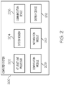
- FIG. 2 is a functional block diagram of a computer system 200, in accordance with the disclosed embodiments. It should be noted that the computer system 200 can be implemented with the computer system 102 depicted in FIG. 1 . In this regard, the computer system 200 shows certain elements and components of the computer system 102 in more detail.
- the computer system 200 generally includes, without limitation: at least one processor 202; a system memory 204 element; a communication device 206; a computation module 208; a notification module 210; and a display device 212.
- FIG. 2 only depicts certain elements that relate to the calculation and presentation of the VNAV Autopilot Mode disengagement techniques, as described in more detail below.
- the at least one processor 202 may be implemented or performed with one or more general purpose processors, a content addressable memory, a digital signal processor, an application specific integrated circuit, a field programmable gate array, any suitable programmable logic device, discrete gate or transistor logic, discrete hardware components, or any combination designed to perform the functions described here.
- the at least one processor 202 may be realized as one or more microprocessors, controllers, microcontrollers, or state machines.
- the at least one processor 202 may be implemented as a combination of computing devices, e.g., a combination of digital signal processors and microprocessors, a plurality of microprocessors, one or more microprocessors in conjunction with a digital signal processor core, or any other such configuration.
- the at least one processor 202 is communicatively coupled to the system memory 204.
- the system memory 204 is configured to store any obtained or generated data associated with flight plan data, Flight Management System (FMS) data, navigation data, Lateral Navigation (LNAV) Autopilot Mode functionality data, Vertical Navigation (VNAV) Autopilot Mode functionality data, or the like.
- the system memory 204 may be realized using any number of devices, components, or modules, as appropriate to the embodiment.
- the computer system 200 could include system memory 204 integrated therein and/or a system memory 204 operatively coupled thereto, as appropriate to the particular embodiment.
- system memory 204 could be realized as RAM memory, flash memory, EPROM memory, EEPROM memory, registers, a hard disk, a removable disk, or any other form of storage medium known in the art.
- the system memory 204 includes a hard disk, which may also be used to support functions of the computer system 200.
- the system memory 204 can be coupled to the at least one processor 202 such that the at least one processor 202 can read information from, and write information to, the system memory 204.
- the system memory 204 may be integral to the at least one processor 202.
- the at least one processor 202 and the system memory 204 may reside in a suitably designed application-specific integrated circuit (ASIC).
- ASIC application-specific integrated circuit
- the communication device 206 is suitably configured to communicate data between the computer system 200 and (i) one or more remote servers; and/or (ii) one or more avionics systems onboard an aircraft.
- the communication device 206 may transmit and receive communications over a wireless local area network (WLAN), the Internet, a satellite uplink/downlink, a cellular network, a broadband network, a wide area network, or the like.
- WLAN wireless local area network
- data received by the communication device 206 may include, without limitation: aircraft position data, flight plan data, navigation data, Flight Management System (FMS) data, LNAV Autopilot Mode data, VNAV Autopilot Mode data, and other data compatible with the computer system 200.
- Data provided by the communication device 206 may include, without limitation, calculated future aircraft position data, time threshold data associated with divergence from the flight path, distance threshold data associated with divergence from the flight path, VNAV Autopilot Mode disengagement data, and the like.
- the computation module 208 is configured to perform calculations to identify a location wherein VNAV Autopilot Mode disengagement is necessary to prevent accumulated error that leads to excessive divergence of the aircraft from the current flight plan.
- the computation module 208 detects LNAV Autopilot Mode disengagement in a decoupled system, determines that a current aircraft position indicates potential divergence from the flight path that exceeds a divergence threshold (e.g., time threshold, distance threshold), and calculates a future aircraft position for VNAV Autopilot Mode disengagement to prevent actual divergence from the flight path that exceeds a divergence threshold.
- a divergence threshold e.g., time threshold, distance threshold
- the notification module 210 is configured to present warnings or notifications in the form of graphical elements and text, to inform the flight crew of a future aircraft position for VNAV Autopilot Mode disengagement.
- the notification module 210 presents a notification using a graphical element to indicate the location of VNAV Autopilot Mode disengagement via the display device 212.
- the notification module 210 presents graphical elements to indicate the location of VNAV Autopilot Mode disengagement and a second location that the aircraft reaches prior to the location of VNAV Autopilot Mode disengagement, via the display device 212.
- notification module 210 present a descent path, a current flight path, a revised flight path based on the location of VNAV Autopilot disengagement, a current aircraft position, and any other data relevant to situational awareness and applicable to the particular type of display device 212 used onboard the aircraft.
- the computation module 208 and/or the notification module 210 may be implemented with (or cooperate with) the at least one processor 202 to perform at least some of the functions and operations described in more detail herein.
- the computation module 208 and/or the notification module 210 may be realized as suitably written processing logic, application program code, or the like.
- the display device 212 is configured to display various icons, text, and/or graphical elements associated with VNAV Autopilot Mode disengagement, including a future aircraft position for VNAV Autopilot Mode disengagement, a descent profile associated with the future aircraft position, warning messages to notify flight crew members of the future aircraft position for VNAV Autopilot Mode disengagement, or the like.
- the display device 212 is communicatively coupled to the at least one processor 202.
- the at least one processor 202 and the display device 212 are cooperatively configured to display, render, or otherwise convey one or more graphical representations or images associated with VNAV Autopilot Mode disengagement, and/or warnings thereto, on the display device 212, as described in greater detail below.
- the display device 212 is realized as an electronic display configured to graphically display an aircraft position for VNAV Autopilot Mode disengagement, as described herein.
- the computer system 200 is an integrated computer system onboard an aircraft, and the display device 212 is located within a cockpit of the aircraft, and is thus implemented as an aircraft display.
- the display device 212 may be implemented as a Primary Flight Display (PFD), a Vertical Situation Display (VSD), a Multi-Function Display (MFD), a Multi-Function Control and Display Unit (MCDU), or other integrated, aircraft onboard display.
- the display device 212 is implemented as a display screen of a standalone, personal computing device (e.g., laptop computer, tablet computer). It will be appreciated that although the display device 212 may be implemented using a single display, certain embodiments may use additional displays (i.e., a plurality of displays) to accomplish the functionality of the display device 112 described herein.
- FIGS. 3-6 illustrate four cases wherein a future aircraft position for Vertical Navigation (VNAV) Autopilot Mode disengagement is calculated by a computer system (e.g., a Flight Management System (FMS) or other computer system communicatively coupled to the FMS).
- VNAV Vertical Navigation
- FMS Flight Management System
- LNAV Lateral Navigation
- the VNAV can continue operation for a period of time before error accumulates, causing the aircraft to diverge from the flight path in such a way as to exceed a divergence threshold.
- Described herein are algorithms to determine the predicted vertical managed mode inactivation (i.e., the VNAV Autopilot Mode) when the managed lateral mode (i.e., the LNAV Autopilot Mode) is inactivated in the various scenarios described with regard to FIGS. 3-6 .
- the four cases illustrate through schematics the operational situations encountered by an aircraft with respect to a curved path. The situations represent change in the vertical managed mode and deactivation of VNAV, which represents change in the vertical managed to manual mode when the lateral mode is disengaged.
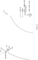
- FIG. 3 is a diagram 300 of a predicted aircraft position 304 for a given time when the aircraft 302 is flying wings-level and converging towards a flight path 306, in accordance with the disclosed embodiments.
- the aircraft 302 is flying a "level" flight, with no roll, and converging onto the curved flight path 306.
- the aircraft 302 is approaching and converging towards the reference trajectory, and this is shown when the predicted cross-track error (XTK) and track angle (TKE) is less than zero: XTK.TKE ⁇ 0.
- XTK predicted cross-track error
- TKE track angle
- the vertical managed mode remains intact as it is evident that the aircraft 302 is converging towards the intended flight path 306.
- the aircraft 302 Because the aircraft 302 is not diverging from the flight path 306 beyond a threshold of allowable divergence, the aircraft 302 continues to use an engaged VNAV Autopilot Mode. Here, there is no calculated applicable point of VNAV Autopilot Mode disengagement due to lack of necessity.
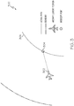
- FIG. 4 is a diagram 400 of a predicted aircraft position (i.e., a future aircraft position 404) for a given time when the aircraft 402 is flying a level flight and diverging from the flight path, in accordance with the disclosed embodiments.
- the aircraft 402 is flying a wings-level flight, with no roll, and diverging off the curved flight path 406.
- a distance and location at which the vertical managed mode is disengaged is a computed value. This location is the predicted aircraft position (i.e., the future aircraft position 404) at which the VNAV Autopilot Mode is disengaged.
- a predicted cross-track error (XTK Pred ) is computed for a given time-out period (T), and the predicted cross-track error (XTK Pred ) is then analyzed to determine whether the predicted cross-track error (XTK Pred ) is within the vertical managed mode dropout corridor.
- the predicted cross-track error indicates that the divergence of the aircraft 402 does not exceed an allowable divergence threshold for the flight path 406.
- the vertical managed mode dropout corridor i.e., the divergence threshold
- the divergence threshold is a fixed tolerance value.
- the divergence threshold is operator modifiable, wherein the user-selected value depends on the need to maintain safe vertical managed mode (i.e., VNAV Autopilot Mode) operations when lateral managed mode (i.e., LNAV Autopilot Mode) is inactivated.
- VNAV Autopilot Mode safe vertical managed mode
- LNAV Autopilot Mode lateral managed mode
- the following algorithms are used to compute the predicted aircraft position (i.e., the future aircraft position 404) for a given time when the aircraft 402 is flying a level flight.
- the predicted cross-track error (XTK Pred ) and ⁇ are unknown parameters, and D is the predicted distance travelled from the point at which the LNAV Autopilot Mode is dropped to the point reached for the time T for a given ground speed.
- XTK is the current cross-track error computed at the time LNAV was disengaged, and R represents the turn radius of the curved path transition.
- the algorithm includes detecting a current action of the aircraft 402, wherein the current action includes the aircraft 402 diverging away from the flight path 406 by flying wings-level away from a curved path, wherein the flight path 406 comprises the curved path; identifying parameters based on the current action, the parameters comprising at least a current aircraft position, the threshold time period, a predicted distance travelled from a point of LNAV disengagement, an ground speed of the aircraft 402, a current cross-track error (XTK) computed at a time of LNAV disengagement, and a turn radius of a transition from the curved path; and computing a predicted cross-track error (XTK Pred ) for a predicted aircraft position (i.e., the future aircraft position 404), using the parameters, wherein the future aircraft position comprises the predicted aircraft position (i.e., the future aircraft position 404).
- XTK current cross-track error
- the predicted cross-track error indicates divergence of the aircraft 402 that is greater than, or less than, a divergence threshold for the computed future aircraft position 404.
- XTK Pred The predicted cross-track error indicates divergence of the aircraft 402 that is greater than, or less than, a divergence threshold for the computed future aircraft position 404.
- FIG. 5 is a diagram 500 of a predicted aircraft position 504 (i.e., calculated future aircraft position) for a given time when the aircraft 502 is banking to attain the target course or heading, in accordance with the disclosed embodiments.
- the aircraft 502 is converging onto the curved path (i.e., the flight path 506) using a specific bank angle to achieve the target course or heading.
- a distance value, ending at a location (i.e., future aircraft position) at which inactivation of the vertical managed mode is a computed value.
- This location is the predicted aircraft position 504 at which the VNAV Autopilot Mode is disengaged.
- a predicted cross-track error (XTK Pred ) is computed for a given time-out period (T), and the predicted cross-track error (XTK Pred ) is then analyzed to determine whether the predicted cross-track error (XTK Pred ) is within the vertical managed mode dropout corridor.
- the predicted cross-track error indicates that the divergence of the aircraft 502 does not exceed an allowable divergence threshold for the flight path 506.
- the predicted cross-track error (XTK Pred ) at time T is e r + XTK, wherein e r is an unknown parameter, and XTK is the current cross-track error computed at the time the LNAV was disengaged.
- L is the predicted distance travelled from the point lateral managed mode (i.e., LNAV Autopilot Mode) is dropped to the point reached for the time T for a given ground speed of the aircraft 502.
- Unknown parameters include: ⁇ , ⁇ , e r .
- the following algorithms are used to calculate the predicted cross-track error (XTK Pred ):
- ⁇ cos ⁇ 1 D L sin ⁇ 2 ⁇ ⁇
- e r L sin ⁇ 2 sin ⁇ + ⁇ 2
- the XTK Pred e r + XTK, which is the predicted cross-track error for a given ground speed at time T.
- VNAV Autopilot Mode the vertical managed mode
- the vertical managed mode is inactivated (i.e., the VNAV Autopilot Mode is disengaged).
- the algorithms for calculating a future aircraft position for disengagement of the VNAV Autopilot Mode include detecting a current action of the aircraft 502, wherein the current action includes the aircraft 502 converging toward the flight path 506 by flying in lateral manual mode and using a particular bank angle to attain a target course or heading of a lateral flight plan, wherein the flight path 506 comprises the lateral flight plan; identifying parameters based on the current action, the parameters comprising at least a current aircraft position, the threshold time period, a predicted distance travelled from a point of LNAV disengagement, an ground speed of the aircraft 502, and a current cross-track error computed at a time of LNAV disengagement; and computing a predicted cross-track error for a predicted aircraft position 504, using the parameters, wherein the future aircraft position comprises the predicted aircraft position 504.
- FIG. 6 is a diagram 600 of a predicted aircraft position for a given time when the aircraft 602 is banking away from the current flight path 606, in accordance with the disclosed embodiments.
- the aircraft 602 is diverging off the curved path using a specific bank angle.
- the aircraft 602 is diverging from the flight path 606 using a turn angle (
- ) is greater than one degree: (
- Increased divergence indicates that maintaining an engaged and active vertical managed mode results in the additional accumulation of error in the absence of an active managed lateral mode.
- the vertical managed mode is disengaged immediately to prevent the increased accumulation of error.
- Computation of a predicted aircraft position for a given time when the aircraft 602 is banking away from the flight path 606 includes detecting a current action of the aircraft 602, wherein the current action includes the aircraft 602 diverging away from the flight path 606 by flying away from a curved path and using a particular bank angle, wherein the flight path 606 comprises the curved path; determining that the future aircraft position is associated with accumulated error, based on the current action; and disengaging the VNAV Autopilot Mode, based on the future aircraft position being associated with accumulated error.
- FIGS. 7-12 illustrate embodiments for presenting warnings, messages, visual indications, and notifications onboard the aircraft, to notify the flight crew of an upcoming location of Vertical Navigation (VNAV) Autopilot Mode disengagement, under conditions wherein the Lateral Navigation (LNAV) Autopilot Mode is currently disengaged and inactive.
- VNAV Vertical Navigation
- LNAV Lateral Navigation
- Such notifications may be presented via aircraft onboard displays, including but not limited to: a Primary Flight Display (PFD), a Multi-Function Display (MFD), a Multi-Function Control and Display Unit (MCDU), a Vertical Situation Display (VSD), or the like.
- PFD Primary Flight Display
- MFD Multi-Function Display
- MCDU Multi-Function Control and Display Unit
- VSD Vertical Situation Display
- FIGS. 7-12 are representations of the methods to provide appropriate cockpit warnings and exemplary embodiments of the warnings.
- FIG. 7 is a diagram 700 of a presentation of indications of (i) an aircraft position for Vertical Navigation (VNAV) Autopilot Mode disengagement, and (ii) an aircraft position at which notifications of VNAV Autopilot Mode disengagement occurs, in accordance with the disclosed embodiments.
- the diagram 700 includes two location points: a first location point 704 and a second location point 706.
- the second location point 706 indicates a location for disengagement of the VNAV Autopilot Mode.
- the first location point 704 indicates a location for the presentation of warnings, alerts, messages, or any type of notification of an upcoming disengagement or inactivation of the VNAV Autopilot Mode.
- the first location point 704 and the second location point 706 are located ahead of the aircraft 702.
- the aircraft 702 encounters the first location point 704 as the first point in a sequence that includes, in order: (1) the first location point 704, and (2) the second location point 706.
- the first location point 704 indicates time and location for presentation of a text message "VNAV DROP AHEAD", which is displayed via an MCDU, MFD, and/or PFD onboard the aircraft 702.
- the first location point 704 is determined based on the calculated location of the future aircraft position at which the vertical managed mode is disengaged or inactivated, wherein the calculated location occurs ahead of the first location point 704.
- VSD Vertical Situation Display
- the first location point 704 is marked or indicated with an arrow.
- the second location point 706 indicates the location at which the vertical managed mode is disengaged.
- the second location point 706 is marked or indicated with an 'X' marker, and the following descent path is indicated using a hashed line.
- FIG. 8 is a diagram of a Vertical Situation Display (VSD) 800 presenting indications of (i) an aircraft position for Vertical Navigation (VNAV) Autopilot Mode disengagement, and (ii) an aircraft position at which notifications of VNAV Autopilot Mode disengagement occurs, in accordance with the disclosed embodiments.
- VSD Vertical Situation Display
- FIG. 8 depicts a simplified embodiment of a graphical interface presented by the VSD 800, and that some implementations of the VSD 800 may include additional elements or components.
- the aircraft 802 On the VSD 800, the aircraft 802 is shown traveling from left to right across the display. During flight, the aircraft 802 encounters the first location point 804 as the first point in a sequence that includes: (1) the first location point 804, (2) the second location point 806, and (3) the descent 808. As shown, the VSD 800 presents the first location point 804 using a first color, the second location point 806 using a second color, and the descent 808 using a dashed line in a third color. It should be appreciated that other embodiments may present each of the first location point 804, the second location point 806, and the descent 808 using any graphical elements that include visually distinguishable characteristics.
- the graphical interface, presented by the VSD 800 provides a visually intuitive summary of the current location of the aircraft 802, the location for disengagement of the VNAV Autopilot Mode, and the location for presenting warnings and notifications associated with disengaging the VNAV Autopilot Mode.
- FIG. 9 is a diagram 900 of another presentation of an indication of an aircraft position for Vertical Navigation (VNAV) Autopilot Mode disengagement, in accordance with the disclosed embodiments.
- the diagram 900 includes one location point: a VNAV disengagement location point 906 indicating a location for disengagement of the VNAV Autopilot Mode of the Flight Management System (FMS).
- the diagram 900 does not show a notification location point indicating a location for the presentation of warnings, alerts, messages, or any type of notification of an upcoming disengagement or inactivation of the VNAV Autopilot Mode.
- the aircraft 902 has already encountered the notification location point, and will encounter the upcoming VNAV disengagement location point 906 as the second location point in a sequence that includes, in order: (1) the notification location point, and (2) the VNAV disengagement location point 906.
- the VNAV disengagement location point 906 is located ahead of the aircraft 902, and the notification location point (not shown) is located behind the aircraft 902.
- the aircraft 902 has already encountered the notification location point, and warnings or alerts associated with the upcoming VNAV disengagement (at the VNAV disengagement location point 906) were presented at the notification location point.
- the warnings, messages, or notifications are generally presented via at least one aircraft onboard display device, which may include a Multi-Function Control and Display Unit (MCDU), a Multi-Function Display (MFD), a Primary Flight Display (PFD), and/or a Vertical Situation Display (VSD).
- MCDU Multi-Function Control and Display Unit
- MFD Multi-Function Display
- PFD Primary Flight Display
- VSD Vertical Situation Display
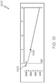
- FIG. 10 is a diagram of a VSD 1000 presenting the notification or warning indicating VNAV Autopilot Mode disengagement, in accordance with the disclosed embodiments. It should be appreciated that FIG. 10 depicts a simplified embodiment of a graphical interface presented by the VSD 1000, and that some implementations of the VSD 1000 may include additional elements or components.
- the aircraft 1002 On the VSD 1000, the aircraft 1002 is shown traveling from left to right across the display. During flight, the aircraft 1002 encounters the VNAV disengagement location point 1006 as the second location point in a sequence that includes: (1) the notification location point, (2) the VNAV disengagement location point 1006, and (3) the descent 1008. The notification location point has already been passed by the aircraft 1002, the notification location point is thus behind the aircraft 1002 during flight, and the notification location point is not shown by the VSD 1000. As shown, the VSD 1000 presents the VNAV disengagement location point 1006 using a first color, and the descent 1008 using a dashed line in a second color.
- each of the VNAV disengagement location point 1006, and the descent 1008 may present each of the VNAV disengagement location point 1006, and the descent 1008 using any graphical elements that include visually distinguishable characteristics.
- the graphical interface, presented by the VSD 1000 provides a visually intuitive summary of the current location of the aircraft 1002, the location for disengagement of the VNAV Autopilot Mode, and the location for presenting warnings and notifications associated with disengaging the VNAV Autopilot Mode.
- FIG. 11 is a diagram 1100 of an aircraft position at which VNAV Autopilot Mode is disengaged, in accordance with the disclosed embodiments.
- the diagram 1100 includes one location point: a VNAV disengagement location point 1106 indicating a location for disengagement of the VNAV Autopilot Mode of the Flight Management System (FMS).
- FMS Flight Management System
- the VNAV disengagement location point 1106 is behind the aircraft 1102 as the aircraft 1102 travels toward a divergence threshold boundary 1110.
- the diagram 1100 does not show a notification location point indicating a location for the presentation of warnings, alerts, messages, and notifications associated with the already-passed disengagement or inactivation of the VNAV Autopilot Mode.
- the aircraft 1102 has already encountered the notification location point, and has already encountered the VNAV disengagement location point 1106 as the second location point in a sequence that includes, in order: (1) the notification location point, and (2) the VNAV disengagement location point 1106.
- the VNAV disengagement location point 1106 is located behind the aircraft 1102, and the notification location point (not shown) is also located behind the aircraft 1102.
- the aircraft 1102 has already encountered the notification location point, and warnings or alerts associated with the upcoming VNAV disengagement (at the VNAV disengagement location point 1106) were presented at the notification location point.
- the warnings, messages, or notifications are generally presented via at least one aircraft onboard display device, which may include a Multi-Function Control and Display Unit (MCDU), a Multi-Function Display (MFD), a Primary Flight Display (PFD), and/or a Vertical Situation Display (VSD).
- MCDU Multi-Function Control and Display Unit
- MFD Multi-Function Display
- PFD Primary Flight Display
- VSD Vertical Situation Display
- the aircraft 1102 has also already encountered the VNAV disengagement location point 1106 and, as a result, the VNAV Autopilot Mode of the Flight Management System (FMS) onboard the aircraft 1102 has been disengaged or inactivated.
- FMS Flight Management System
- FIG. 12 is a diagram of a Vertical Situation Display (VSD) 1200 presenting a descent path 1208 associated with the aircraft position at which VNAV Autopilot Mode is disengaged, in accordance with the disclosed embodiments.
- VSD Vertical Situation Display
- FIG. 12 depicts a simplified embodiment of a graphical interface presented by the VSD 1200, and that some implementations of the VSD 1200 may include additional elements or components.
- the aircraft 1202 On the VSD 1200, the aircraft 1202 is shown traveling from left to right across the display. During flight, the aircraft 1202 has already encountered a notification location point and a VNAV disengagement location point, in a sequence that includes: (1) the notification location point, (2) the VNAV disengagement location point, and (3) the descent path 1208.
- the notification location point has already been passed by the aircraft 1202, the notification location point is thus behind the aircraft 1202 during flight, and the notification location point is not shown by the VSD 1200.
- the VNAV disengagement location point has already been passed by the aircraft 1202, the VNAV disengagement location point is thus behind the aircraft 1202 during flight, and the VNAV disengagement location point is not shown by the VSD 1200.
- the aircraft 1202 is currently located at the beginning of the descent path 1208, which is presented as a dashed line.
- the graphical interface, presented by the VSD 1200 provides a visually intuitive summary of the current location of the aircraft 1202, the location for the descent path 1208, the location for disengagement of the VNAV Autopilot Mode, and the location for presenting warnings and notifications associated with disengaging the VNAV Autopilot Mode.
- FIG. 13 is a flow chart that illustrates an embodiment of a process 1300 for providing mode data onboard an aircraft, during operation of a Flight Management System (FMS) using VNAV Autopilot Mode and when the FMS has disengaged a Lateral Navigation (LNAV) Autopilot Mode, in accordance with the disclosed embodiments.
- the process 1300 detects a changed aircraft position indicating divergence from a flight path (step 1302).
- One suitable methodology for detecting a changed aircraft position indicating divergence from a flight path is described below with reference to FIG. 14 . Divergence from the flight path is calculated based on an allowable divergence threshold.
- the process 1300 determines that the aircraft has deviated from the flight path, and that the extent of the deviation exceeds an allowable quantity, wherein the allowable quantity is less than the divergence threshold.
- the process 1300 detects that the aircraft is located at the changed aircraft position, wherein the changed aircraft position exceeds the divergence threshold. In other words, the process 1300 detects that the deviation of the aircraft is larger than the allowable quantity of divergence.
- the process 1300 calculates a future aircraft position for VNAV Autopilot Mode disengagement, based on the changed aircraft position, a predicted cross-track error, and the divergence from the flight plan (step 1304). Suitable methodologies for calculating a future aircraft position for VNAV Autopilot Mode disengagement are described below with reference to FIGS. 15-16 .
- the future aircraft position i.e., a predicted aircraft position
- LNAV Lateral Navigation
- Cross-track error i.e., current cross-track error
- the cross-track error is a quantity of deviation from the flight path, based on the current position of the aircraft.
- a predicted cross-track error is a calculated error value associated with lateral navigation accuracy when the aircraft is located at the future aircraft position.
- the predicted cross-track error is a quantity of deviation from the flight path, based on the future aircraft position.
- the process 1300 uses the current aircraft location and current cross-track error to calculate a predicted cross-track error and a future aircraft position.
- the process 1300 then presents the changed aircraft position and the future aircraft position when operating in the VNAV Autopilot Mode, via a display device communicatively coupled to the FMS (step 1306).
- the process 1300 presents the changed aircraft position and the future aircraft position via Multi-Function Control and Display Unit (MCDU), Multi-Function Display (MFD), Primary Flight Display (PFD), Vertical Situation Display (VSD), or any other display device integrated into the aircraft.
- the process 1300 presents the changed aircraft position and the future aircraft position via a personal computing device (e.g., tablet computer, smartphone, laptop) configured to store, maintain, and execute an Electronic Flight Bag (EFB) application for use onboard the aircraft.
- EFB Electronic Flight Bag
- the process 1300 also determines whether the future aircraft position is located on the flight path (decision 1308). When the future aircraft position is located on the flight path (the "Yes” branch of 1308), then the process 1300 continues engagement of the VNAV Autopilot Mode (step 1310). The future aircraft position and the predicted cross-track error are used to calculate an amount of divergence of the aircraft from the flight path caused by the use of the VNAV Autopilot Mode when the LNAV Autopilot Mode is disengaged. Since the location of the future aircraft position is located on the flight path, there is no divergence from the flight path indicated by the future aircraft position. Thus, the process 1300 maintains the VNAV Autopilot Mode.
- the process 1300 disengages the VNAV Autopilot Mode of the FMS, based on the changed aircraft position and the future aircraft position for VNAV Autopilot Mode disengagement (step 1312). Since the future aircraft position is not located on the flight path, then the future aircraft position indicates divergence from the flight path, and in response, the process 1300 disengages the VNAV Autopilot Mode.
- the process 1300 also calculates a descent path for the aircraft, after disengagement of the VNAV Autopilot Mode (step 1314). Although the VNAV Autopilot Mode descent path (VNAV DES path) does not change when the VNAV Autopilot Mode is disengaged, the aircraft no longer controls the descent path and vertical guidance is based on the current default state in non-managed mode conditions.
- the process 1300 calculates the descent path based on the current default state in non-managed mode conditions.
- the process 1300 then presents the descent path, via the display device (step 1316).
- the process 1300 presents the changed aircraft position (step 1306), the future aircraft position (step 1306), and the descent path (step 1316).
- the process 1300 provides an intuitive visual representation of a current flight situation, onboard the aircraft.
- FIG. 14 is a flow chart that illustrates an embodiment of a process 1400 for detecting a changed aircraft position indicating divergence from a flight path, in accordance with the disclosed embodiments. It should be appreciated that the process 1400 described in FIG. 14 represents one embodiment of step 1302 described above in the discussion of FIG. 13 , including additional detail.
- the process 1400 computes a predicted cross-track error for a threshold time period of a current flight (step 1402), based on a current aircraft position and a current cross-track error.
- a current aircraft position is an actual location of the aircraft at the present time.
- the current cross-track error is a current error value associated with lateral navigation accuracy.
- the cross-track error is a quantity of deviation from the flight path, based on the current position of the aircraft.
- a predicted cross-track error is a calculated error value associated with lateral navigation accuracy when the aircraft is located at the future aircraft position.
- the predicted cross-track error is a quantity of deviation from the flight path, based on the future aircraft position. Specific formulas used to calculate the predicted cross-track error are described in detail with regard to FIGS. 3-6 , and will not be redundantly described here.
- the process 1400 determines that the predicted cross-track error indicates divergence from the flight path (step 1404). Divergence from the flight path may be indicated by exceeding maximum allowed time period for deviation from the flight path, or by exceeding a maximum allowed distance for deviation from the flight path. In a first embodiment, the process 1400 determines that the predicted cross-track error indicates divergence from the flight path for a time period that is greater than the threshold time period. When the time period is greater than the threshold time period, the changed aircraft position indicates that the aircraft has diverged from the flight path for the threshold time period of the current flight. Thus, divergence of the aircraft from the flight path is determined to exceed the allowable limit set by the threshold time period.
- Excessive divergence initiates disengagement of the VNAV Autopilot Mode of the aircraft Flight Management System (FMS) under conditions of an already-disengaged LNAV Autopilot Mode of the aircraft FMS.
- FMS Flight Management System
- the process 1400 determines that the predicted cross-track error is greater than a distance threshold.
- the predicted cross-track error is greater than the distance threshold
- the changed aircraft position indicates that the aircraft has crossed a distance threshold for a lateral containment area of the flight path.
- divergence of the aircraft from the flight path is determined to exceed the allowable limit set by the distance threshold. Divergence that exceeds the allowable limit may be termed "excessive divergence", and excessive divergence initiates disengagement of the VNAV Autopilot Mode of the aircraft Flight Management System (FMS) under conditions of an already-disengaged LNAV Autopilot Mode of the aircraft FMS.
- FMS Flight Management System
- the process 1400 computes a predicted cross-track error for a given time-out period, and then the process 1400 analyzes predicted cross-track error to determine whether the predicted cross-track error is within the vertical managed mode dropout corridor.
- the predicted cross-track error indicates that the divergence of the aircraft does not exceed an allowable divergence threshold for the flight path.
- the vertical managed mode dropout corridor i.e., the divergence threshold
- the divergence threshold is operator modifiable, wherein the user-selected value depends on the need to maintain safe vertical managed mode (i.e., VNAV Autopilot Mode) operations when lateral managed mode (i.e., LNAV Autopilot Mode) is inactivated.
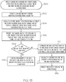
- FIG. 15 is a flow chart that illustrates a first embodiment of a process 1500 for calculating a future aircraft position for VNAV Autopilot Mode disengagement, in accordance with the disclosed embodiments. It should be appreciated that the process 1500 described in FIG. 15 represents one embodiment of step 1304 described above in the discussion of FIG. 13 , including additional detail. Contemplated herein are embodiments described previously with regard to FIGS. 4-5 .
- the process 1500 detects a current action of the aircraft (step 1502).
- the current action of the aircraft includes an action of the aircraft in relation to the flight path.
- the current action includes the aircraft diverging away from the flight path by flying wings-level away from a curved path, wherein the flight path comprises the curved path.
- the current action includes the aircraft converging toward the flight path by flying in lateral manual mode and using a particular bank angle to attain a target course or heading of a lateral flight plan, wherein the flight path comprises the lateral flight plan.
- parameters generally include, but are not limited to: a current aircraft position, the threshold time period, a predicted distance travelled from a point of LNAV disengagement, a ground speed of the aircraft, a current cross-track error computed at a time of LNAV disengagement, and a turn radius of a transition from the curved path.
- parameters generally include, but are not limited to: a current aircraft position, the threshold time period, a predicted distance travelled from a point of LNAV disengagement, a ground speed of the aircraft, and a current cross-track error computed at a time of LNAV disengagement.
- the current aircraft position is defined as an actual location of the aircraft at the present time.
- Current cross-track error is defined as a current error value associated with lateral navigation accuracy.
- the cross-track error is a quantity of deviation from the flight path, based on the current position of the aircraft.
- the process 1500 then computes the predicted cross-track error for a predicted aircraft position using the parameters, wherein the future aircraft position comprises the predicted aircraft position (step 1506).
- a future aircraft position i.e., a predicted aircraft position
- LNAV Lateral Navigation
- a predicted cross-track error is a calculated error value associated with lateral navigation accuracy when the aircraft is located at the future aircraft position.
- the predicted cross-track error is a quantity of deviation from the flight path, based on the future aircraft position.
- the process 1500 also compares the predicted cross-track error to a threshold distance, and when the predicted cross-track error is less than the threshold distance, the process 1500 retains engagement of the VNAV autopilot mode. However, when the predicted cross-track error is greater than the threshold distance, the process 1500 disengages the VNAV Autopilot Mode, as described previously with regard to FIG. 13 .
- FIG. 16 is a flow chart that illustrates a second embodiment of a process 1600 for calculating a future aircraft position for VNAV Autopilot Mode disengagement, in accordance with the disclosed embodiments. It should be appreciated that the process 1600 described in FIG. 16 represents one embodiment of step 1304 described above in the discussion of FIG. 13 , including additional detail. Contemplated herein are embodiments described previously with regard to FIGS. 3 and 6 .
- the process 1600 detects a current action of the aircraft (step 1602).
- the current action of the aircraft includes an action of the aircraft in relation to the flight path.
- the current action includes the aircraft converging toward the flight path by flying wings-level toward a curved path, wherein the flight path comprises the curved path.
- the current action includes the aircraft diverging away from the flight path by flying away from a curved path and using a particular bank angle, wherein the flight path comprises the curved path.
- the process 1600 determines divergence parameters associated with a future aircraft position, based on the current action (step 1604).
- Divergence parameters include a future aircraft position associated with an outlier position.
- Embodiments of determining the divergence parameters include: (1) determining that the future aircraft position is located on the flight path, based on the current action; and (2) determining that the future aircraft position is associated with accumulated error, based on the current action.
- the future aircraft position is located on the flight path, and thus, the future aircraft position does not indicate any amount of divergence from the flight path.
- the future aircraft position on the flight path is associated with very low, or zero, divergence.
- the future aircraft position is associated with a very high level of divergence that far exceeds a divergence threshold (i.e., a level of allowable divergence from the flight path.
- a divergence threshold i.e., a level of allowable divergence from the flight path.
- the aircraft is diverging from the flight path using a turn angle (
- Increased divergence indicates that maintaining an engaged and active vertical managed mode results in the accumulation of a high level of error in the absence of an active managed lateral mode.
- the process 1600 then continues engagement or disengages the VNAV Autopilot Mode, based on the divergence parameter (step 1606).
- the future aircraft position is associated with no divergence, and thus, the VNAV Autopilot Mode is not disengaged.
- the future aircraft position is associated with a high level of accumulated error due to the turn angle of the aircraft, and the vertical managed mode (i.e., VNAV Autopilot Mode) is disengaged immediately to prevent the increased accumulation of error.
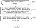
- FIG. 17 is a flow chart that illustrates an embodiment of a process 1700 for presenting notification data onboard the aircraft, in accordance with the disclosed embodiments. Contemplated herein are embodiments described previously with regard to FIGS. 7-12 .
- the process 1700 identifies a warning point along the flight path, wherein the warning point is located between the current aircraft position and the future aircraft position (step 1702).
- the process 1700 computes the location of the warning point using the current aircraft position, the current cross-track error, the previously-calculated future aircraft position, and the predicted cross-track error (see FIGS. 13-16 and associated description).
- the warning point is a location that the aircraft passes through during flight, wherein the warning point is located between the current aircraft position and the future aircraft position.
- the warning point is a location at which notification of the upcoming point of VNAV Autopilot Mode disengagement is presented, such that a flight crew is made aware and may take action.
- the process 1700 then presents graphical elements representing the changed aircraft position, the future aircraft position, and the warning point (step 1704).
- the process 1700 provides visual indications of the current aircraft position (i.e., the changed aircraft position), the future aircraft position, and the upcoming warning point, to enhance flight crew situational awareness.
- the process 1700 presents a text notification of the future aircraft position for VNAV Autopilot Mode disengagement, via a Primary Flight Display (PFD), wherein the display device comprises the PFD.
- PFD Primary Flight Display
- the process 1700 when the aircraft reaches the warning point during the current flight, the process 1700 presents a second graphical element indicating the future aircraft position for VNAV Autopilot Mode disengagement, via a Vertical Situation Display (VSD), wherein the display device comprises the VSD.
- VSD Vertical Situation Display
- Other embodiments of the process 1700 may present any type of notification, warning, alert, or message that includes any combination of graphical elements, text, auditory alerts, or the like.
- processes 1300-1700 may be performed by software, hardware, firmware, or any combination thereof.
- the preceding description of processes 1300-1700 may refer to elements mentioned above in connection with FIGS. 1-12 .
- portions of processes 1300-1700 may be performed by different elements of the described system.
- processes 1300-1700 may include any number of additional or alternative tasks, the tasks shown in FIGS. 13-17 need not be performed in the illustrated order, and processes 1300-1700 may be incorporated into a more comprehensive procedure or process having additional functionality not described in detail herein.
- one or more of the tasks shown in FIGS. 13-17 could be omitted from embodiments of the processes 1300-1700 as long as the intended overall functionality remains intact.
- an embodiment of a system or a component may employ various integrated circuit components, e.g., memory elements, digital signal processing elements, logic elements, look-up tables, or the like, which may carry out a variety of functions under the control of one or more microprocessors or other control devices.
- integrated circuit components e.g., memory elements, digital signal processing elements, logic elements, look-up tables, or the like, which may carry out a variety of functions under the control of one or more microprocessors or other control devices.
- various elements of the systems described herein are essentially the code segments or instructions that perform the various tasks.
- the program or code segments can be stored in a processor-readable medium or transmitted by a computer data signal embodied in a carrier wave over a transmission medium or communication path.
- the "computer-readable medium”, “processor-readable medium”, or “machine-readable medium” may include any medium that can store or transfer information. Examples of the processor-readable medium include an electronic circuit, a semiconductor memory device, a ROM, a flash memory, an erasable ROM (EROM), a floppy diskette, a CD-ROM, an optical disk, a hard disk, a fiber optic medium, a radio frequency (RF) link, or the like.
- RF radio frequency
- the computer data signal may include any signal that can propagate over a transmission medium such as electronic network channels, optical fibers, air, electromagnetic paths, or RF links.
- the code segments may be downloaded via computer networks such as the Internet, an intranet, a LAN, or the like.
- Coupled means that one element/node/feature is directly or indirectly joined to (or directly or indirectly communicates with) another element/node/feature, and not necessarily mechanically.
- connected means that one element/node/feature is directly joined to (or directly communicates with) another element/node/feature, and not necessarily mechanically.
- modules Some of the functional units described in this specification have been referred to as "modules" in order to more particularly emphasize their implementation independence.
- functionality referred to herein as a module may be implemented wholly, or partially, as a hardware circuit comprising custom VLSI circuits or gate arrays, off-the-shelf semiconductors such as logic chips, transistors, or other discrete components.
- a module may also be implemented in programmable hardware devices such as field programmable gate arrays, programmable array logic, programmable logic devices, or the like. Modules may also be implemented in software for execution by various types of processors.
- An identified module of executable code may, for instance, comprise one or more physical or logical modules of computer instructions that may, for instance, be organized as an object, procedure, or function.
- the executables of an identified module need not be physically located together, but may comprise disparate instructions stored in different locations that, when joined logically together, comprise the module and achieve the stated purpose for the module.
- a module of executable code may be a single instruction, or many instructions, and may even be distributed over several different code segments, among different programs, and across several memory devices.
- operational data may be embodied in any suitable form and organized within any suitable type of data structure. The operational data may be collected as a single data set, or may be distributed over different locations including over different storage devices, and may exist, at least partially, merely as electronic signals on a system or network.
Landscapes
- Engineering & Computer Science (AREA)
- Aviation & Aerospace Engineering (AREA)
- Physics & Mathematics (AREA)
- General Physics & Mathematics (AREA)
- Radar, Positioning & Navigation (AREA)
- Remote Sensing (AREA)
- Automation & Control Theory (AREA)
- Traffic Control Systems (AREA)
- Navigation (AREA)
Abstract
Description
- Embodiments of the subject matter described herein relate generally to providing Vertical Navigation (VNAV) Autopilot Mode data onboard an aircraft. More particularly, embodiments of the subject matter relate to providing aircraft positions for VNAV Autopilot Mode disengagement during use of a decoupled and disengaged LNAV Autopilot Mode.
- Automation of flight processes and aircraft onboard equipment increases efficiency and safety during operation of the aircraft. At the same time, such automated systems can complete action items and make changes whether or not flight crew members are actively aware of the action items and/or changes. Situational awareness is critical, such that the flight crew can prepare for upcoming automated changes during the flight, accommodate workload and tasking prioritization, and base operational decisions on such upcoming automated changes. Examples of automated processes may include, without limitation, Lateral Navigation (LNAV) Autopilot Modes and Vertical Navigation (VNAV) Autopilot Modes. The VNAV function aids the flight crew to control to the desired vertical path with the consideration of altitude and speed, and the VNAV function is also responsible for guiding the aircraft when it has diverged from the descent trajectory. Generally, the VNAV commanded trajectories and the modes change autonomously as flight conditions evolve during flight.
- A situation requiring a VNAV mode transition during high workload phases of flight (e.g., descent flight phase, approach flight phase) may not be immediately recognizable to flight crew members. Typical aircraft display configurations may present multiple VNAV commands and/or present a combination of VNAV commands with graphical elements and text associated with other systems, processes, or modes. Such display configurations may require close attention to detail, and thus increased pilot workload, to decipher a current VNAV mode and potentially applicable VNAV mode changes.
- Accordingly, it is desirable to provide increased situational awareness data (e.g., LNAV and VNAV mode data) during flight. Furthermore, other desirable features and characteristics will become apparent from the subsequent detailed description and the appended claims, taken in conjunction with the accompanying drawings and the foregoing technical field and background.
- Some embodiments of the present disclosure provide a method for providing mode data, onboard an aircraft, during operation of a Flight Management System (FMS) using a Vertical Navigation (VNAV) Autopilot Mode. When the FMS has disengaged a Lateral Navigation (LNAV) Autopilot Mode, the method detects a changed aircraft position indicating divergence from a flight path, wherein the changed aircraft position comprises a current aircraft position; calculates a future aircraft position for VNAV Autopilot Mode disengagement, based on the changed aircraft position, a predicted cross-track error, and the divergence from the flight path; and presents the changed aircraft position and the future aircraft position when operating in the VNAV Autopilot Mode, via a display device communicatively coupled to the FMS. Additionally, when the future aircraft position is not on the flight path, the method disengages the VNAV Autopilot Mode of the FMS, based on the changed aircraft position and the future aircraft position for VNAV Autopilot Mode disengagement; calculates a descent path for the aircraft, after disengagement of the VNAV Autopilot Mode; and presents the descent path, via the display device.
- Some embodiments of the present disclosure provide a system for providing mode data, onboard an aircraft, during operation of a Flight Management System (FMS) using a Vertical Navigation (VNAV) Autopilot Mode. The system includes a system memory element; the Flight Management System (FMS), configured to: engage and disengage a Lateral Navigation (LNAV) Autopilot Mode during flight; and engage and disengage the VNAV Autopilot Mode during the flight, wherein the LNAV Autopilot Mode and the VNAV Autopilot Mode comprise decoupled modes configured to operate independently; a display device, configured to present an aircraft position during the flight; and at least one processor, communicatively coupled to the system memory element, the FMS, and the display device. When the FMS has disengaged the Lateral Navigation (LNAV) Autopilot Mode, the at least one processor is configured to: detect a changed aircraft position indicating divergence from a flight path, wherein the changed aircraft position comprises a current aircraft position; calculate a future aircraft position for VNAV Autopilot Mode disengagement, based on the changed aircraft position, a predicted cross-track error, and the divergence from the flight path; present the changed aircraft position and the future aircraft position when operating in the VNAV Autopilot Mode, via the display device communicatively coupled to the FMS; when the future aircraft position is not on the flight path, disengage the VNAV Autopilot Mode of the FMS, based on the changed aircraft position and the future aircraft position for VNAV Autopilot Mode disengagement; calculate a descent path for the aircraft, after disengagement of the VNAV Autopilot Mode; and present the descent path, via the display device.
- This summary is provided to introduce a selection of concepts in a simplified form that are further described below in the detailed description. This summary is not intended to identify key features or essential features of the claimed subject matter, nor is it intended to be used as an aid in determining the scope of the claimed subject matter.
- A more complete understanding of the subject matter may be derived by referring to the detailed description and claims when considered in conjunction with the following figures, wherein like reference numbers refer to similar elements throughout the figures.
-
FIG. 1 is a diagram of a system for providing mode data onboard an aircraft, in accordance with the disclosed embodiments; -
FIG. 2 is a functional block diagram of a computing device, in accordance with the disclosed embodiments; -
FIG. 3 is a diagram of a predicted aircraft position for a given time when the aircraft is flying wings-level and converging towards the path, in accordance with the disclosed embodiments; -
FIG. 4 is a diagram of a predicted aircraft position for a given time when the aircraft is flying a level flight and diverging from the flight path, in accordance with the disclosed embodiments; -
FIG. 5 is a diagram of a predicted aircraft position for a given time when the aircraft is banking to attain the target course or heading, in accordance with the disclosed embodiments; -
FIG. 6 is a diagram of a predicted aircraft position for a given time when the aircraft is banking away from the current flight path, in accordance with the disclosed embodiments; -
FIG. 7 is a diagram of a presentation of indications of (i) an aircraft position for Vertical Navigation (VNAV) Autopilot Mode disengagement, and (ii) an aircraft position at which notifications of VNAV Autopilot Mode disengagement occurs, in accordance with the disclosed embodiments; -
FIG. 8 is a diagram of a Vertical Situation Display (VSD) 800 presenting indications of (i) an aircraft position for Vertical Navigation (VNAV) Autopilot Mode disengagement, and (ii) an aircraft position at which notifications of VNAV Autopilot Mode disengagement occurs, in accordance with the disclosed embodiments; -
FIG. 9 is a diagram of another presentation of indications of (i) an aircraft position for Vertical Navigation (VNAV) Autopilot Mode disengagement, and (ii) an aircraft position at which notifications of VNAV Autopilot Mode disengagement occurs, in accordance with the disclosed embodiments; -
FIG. 10 is a diagram of a VSD presenting the notification or warning indicating VNAV Autopilot Mode disengagement, in accordance with the disclosed embodiments; -
FIG. 11 is a diagram of an aircraft position at which VNAV Autopilot Mode is disengaged, in accordance with the disclosed embodiments; -
FIG. 12 is a diagram of a VSD presenting a descent path associated with the aircraft position at which VNAV Autopilot Mode is disengaged, in accordance with the disclosed embodiments; -
FIG. 13 is a flow chart that illustrates an embodiment of a process for providing mode data onboard an aircraft, during operation of a Flight Management System (FMS) using VNAV Autopilot Mode and when the FMS has disengaged a Lateral Navigation (LNAV) Autopilot Mode, in accordance with the disclosed embodiments; -
FIG. 14 is a flow chart that illustrates an embodiment of a process for detecting a changed aircraft position indicating divergence from a flight path, in accordance with the disclosed embodiments; -
FIG. 15 is a flow chart that illustrates a first embodiment of a process for calculating a future aircraft position for VNAV Autopilot Mode disengagement, in accordance with the disclosed embodiments; -
FIG. 16 is a flow chart that illustrates a second embodiment of a process for calculating a future aircraft position for VNAV Autopilot Mode disengagement, in accordance with the disclosed embodiments; and -
FIG. 17 is a flow chart that illustrates an embodiment of a process for presenting notification data onboard the aircraft, in accordance with the disclosed embodiments. - The following detailed description is merely illustrative in nature and is not intended to limit the embodiments of the subject matter or the application and uses of such embodiments. As used herein, the word "exemplary" means "serving as an example, instance, or illustration." Any implementation described herein as exemplary is not necessarily to be construed as preferred or advantageous over other implementations. Furthermore, there is no intention to be bound by any expressed or implied theory presented in the preceding technical field, background, brief summary or the following detailed description.
- The subject matter presented herein relates to systems and methods for detecting that the LNAV has been temporarily disengaged in a decoupled system, and maintaining engagement of the VNAV during a short period of time that errors are generally minimal. More specifically, the subject matter relates to determining an appropriate time and/or location for disengagement of the VNAV, when the VNAV can no longer continue operation without significant error. Contemplated herein are techniques for detecting divergence of the aircraft from the flight path, calculating a future position of the aircraft exceeding a divergence threshold, and disengaging the VNAV when the aircraft has exceeded the divergence threshold.
- Certain terminologies are used with regard to the various embodiments of the present disclosure. A Flight Management System (FMS) is a specialized computer system that automates various in-flight processes, including in-flight management of the flight plan. The FMS uses a Vertical Navigation (VNAV) Autopilot Mode and a Lateral Navigation (LNAV) Autopilot Mode. The FMS mode is normally termed LNAV for the lateral flight plan and VNAV for the vertical flight plan. The VNAV provides speed and pitch or altitude targets, and the LNAV provides roll steering command to the autopilot. Generally, the VNAV Autopilot Mode and the LNAV Autopilot Mode of an FMS are "coupled", or in other words, functions such that the VNAV and the LNAV are either (i) both engaged (i.e., both VNAV and LNAV are active and operational) or (ii) both disengaged (i.e., both VNAV and LNAV are inactive and not currently operational). Decoupling of the VNAV and LNAV Autopilot Modes permits the VNAV to continue to be engaged, active, and operational when the LNAV is disengaged.
- A flight path is the actual or planned course of an aircraft, wherein the aircraft is required to maintain lateral navigation accuracy within a lateral containment area of the flight path. A current aircraft location is an actual position of the aircraft at the present time. A future aircraft position (i.e., a predicted aircraft position) is a potential location of the aircraft at a future time, which is calculated based on the current aircraft location at which the Lateral Navigation (LNAV) Autopilot Mode is disengaged and a current cross-track error. Cross-track error is a current error value associated with lateral navigation accuracy. In other words, the cross-track error is a quantity of deviation from the flight path, based on the current position of the aircraft. A predicted cross-track error is a calculated error value associated with lateral navigation accuracy when the aircraft is located at the future aircraft position. The predicted cross-track error is a quantity of deviation from the flight path, based on the future aircraft position.
- Turning now to the figures,
FIG. 1 is a diagram of asystem 100 for providing mode data onboard an aircraft, in accordance with the disclosed embodiments. Thesystem 100 operates to compute and present a future aircraft position to disengage the Vertical Navigation (VNAV) Autopilot Mode, when the Lateral Navigation (LNAV) Autopilot Mode has already been disengaged, to avoid accumulation of error during the use of the decoupled VNAV. Thesystem 100 may include, without limitation, acomputer system 102 that communicates with one ormore avionics systems 106 onboard theaircraft 104 and at least oneserver system 108, via adata communication network 110. In practice, certain embodiments of thesystem 100 may include additional or alternative elements and components, as desired for the particular application. - The
computer system 102 may be implemented by any computing device that includes at least one processor, some form of memory hardware, a user interface, and communication hardware. For example, thecomputer system 102 may be implemented using a personal computing device, such as a tablet computer, a laptop computer, a personal digital assistant (PDA), a smartphone, or the like. In this scenario, thecomputer system 102 is capable of storing, maintaining, and executing an Electronic Flight Bag (EFB) application configured to compute a future aircraft position for VNAV disengagement. In other embodiments, thecomputer system 102 may be implemented using any avionics system or other computing device onboard theaircraft 104, which is configured to compute a future aircraft position for VNAV disengagement. For example, thecomputer system 102 may be implemented using a Flight Management System (FMS) onboard theaircraft 104. - The
aircraft 104 may be any aviation vehicle equipped with a Flight Management System (FMS) using a decoupled VNAV Autopilot Mode and an LNAV Autopilot Mode, and for which computing a future aircraft position for VNAV disengagement is relevant and applicable during completion of a flight plan. Theaircraft 104 may be implemented as an airplane, helicopter, spacecraft, hovercraft, or the like. The one ormore avionics systems 106 may include a Flight Management System (FMS), navigation devices, aircraft onboard display devices, or the like. Data obtained from the one ormore avionics systems 106 may include, without limitation: current flight data, flight path data, navigation data, aircraft performance data, or the like. - The
server system 108 may include any number of application servers, and each server may be implemented using any suitable computer. In some embodiments, theserver system 108 includes one or more dedicated computers. In some embodiments, theserver system 108 includes one or more computers carrying out other functionality in addition to server operations. Theserver system 108 may store and provide any type of data used to calculate a future aircraft position for VNAV Autopilot Mode disengagement. Such data may include, without limitation: flight plan data, navigation system data, aircraft data, and other data compatible with thecomputer system 102. - The
computer system 102 is usually located onboard theaircraft 104, and thecomputer system 102 communicates with the one ormore avionics systems 106 via wired and/or wireless communication connection. Thecomputer system 102 and theserver system 108 are generally disparately located, and thecomputer system 102 communicates with theserver system 108 via thedata communication network 110 and/or via communication mechanisms onboard theaircraft 104. - The
data communication network 110 may be any digital or other communications network capable of transmitting messages or data between devices, systems, or components. In certain embodiments, thedata communication network 110 includes a packet switched network that facilitates packet-based data communication, addressing, and data routing. The packet switched network could be, for example, a wide area network, the Internet, or the like. In various embodiments, thedata communication network 110 includes any number of public or private data connections, links or network connections supporting any number of communications protocols. Thedata communication network 110 may include the Internet, for example, or any other network based upon TCP/IP or other conventional protocols. In various embodiments, thedata communication network 110 could also incorporate a wireless and/or wired telephone network, such as a cellular communications network for communicating with mobile phones, personal digital assistants, and/or the like. Thedata communication network 110 may also incorporate any sort of wireless or wired local and/or personal area networks, such as one or more IEEE 802.3, IEEE 802.16, and/or IEEE 802.11 networks, and/or networks that implement a short range (e.g., Bluetooth) protocol. For the sake of brevity, conventional techniques related to data transmission, signaling, network control, and other functional aspects of the systems (and the individual operating components of the systems) may not be described in detail herein. - Typically, the
computer system 102 is implemented as an FMS or a computing device or other avionics system communicatively coupled to the FMS. During typical operation, thecomputer system 102 detects that the LNAV has been temporarily disengaged in a decoupled system (i.e., a system wherein the LNAV and VNAV are decoupled and may be engaged or disengaged independently), and maintains engagement of the VNAV during a short period of time that errors are generally minimal. Thecomputer system 102 determines an appropriate time and location for disengagement of the VNAV, when the VNAV can no longer continue operation without significant error. Thecomputer system 102 performs this functionality by detecting divergence of the aircraft from the flight path, calculating a future position of the aircraft exceeding a divergence threshold, and disengaging the VNAV when the aircraft has exceeded the divergence threshold. Thecomputer system 102 also presents notifications and/or warnings (via one or more displays onboard the aircraft or a personal computing device) to inform the flight crew of the computed future aircraft position for VNAV Autopilot Mode disengagement. -
FIG. 2 is a functional block diagram of acomputer system 200, in accordance with the disclosed embodiments. It should be noted that thecomputer system 200 can be implemented with thecomputer system 102 depicted inFIG. 1 . In this regard, thecomputer system 200 shows certain elements and components of thecomputer system 102 in more detail. Thecomputer system 200 generally includes, without limitation: at least oneprocessor 202; asystem memory 204 element; acommunication device 206; acomputation module 208; anotification module 210; and adisplay device 212. These elements and features of thecomputer system 200 may be operatively associated with one another, coupled to one another, or otherwise configured to cooperate with one another as needed to support the desired functionality - in particular, compute a future aircraft position for VNAV disengagement and provide notification of such, as described herein. For ease of illustration and clarity, the various physical, electrical, and logical couplings and interconnections for these elements and features are not depicted inFIG. 2 . Moreover, it should be appreciated that embodiments of thecomputer system 200 will include other elements, modules, and features that cooperate to support the desired functionality. For simplicity,FIG. 2 only depicts certain elements that relate to the calculation and presentation of the VNAV Autopilot Mode disengagement techniques, as described in more detail below. - The at least one
processor 202 may be implemented or performed with one or more general purpose processors, a content addressable memory, a digital signal processor, an application specific integrated circuit, a field programmable gate array, any suitable programmable logic device, discrete gate or transistor logic, discrete hardware components, or any combination designed to perform the functions described here. In particular, the at least oneprocessor 202 may be realized as one or more microprocessors, controllers, microcontrollers, or state machines. Moreover, the at least oneprocessor 202 may be implemented as a combination of computing devices, e.g., a combination of digital signal processors and microprocessors, a plurality of microprocessors, one or more microprocessors in conjunction with a digital signal processor core, or any other such configuration. - The at least one
processor 202 is communicatively coupled to thesystem memory 204. Thesystem memory 204 is configured to store any obtained or generated data associated with flight plan data, Flight Management System (FMS) data, navigation data, Lateral Navigation (LNAV) Autopilot Mode functionality data, Vertical Navigation (VNAV) Autopilot Mode functionality data, or the like. Thesystem memory 204 may be realized using any number of devices, components, or modules, as appropriate to the embodiment. Moreover, thecomputer system 200 could includesystem memory 204 integrated therein and/or asystem memory 204 operatively coupled thereto, as appropriate to the particular embodiment. In practice, thesystem memory 204 could be realized as RAM memory, flash memory, EPROM memory, EEPROM memory, registers, a hard disk, a removable disk, or any other form of storage medium known in the art. In certain embodiments, thesystem memory 204 includes a hard disk, which may also be used to support functions of thecomputer system 200. Thesystem memory 204 can be coupled to the at least oneprocessor 202 such that the at least oneprocessor 202 can read information from, and write information to, thesystem memory 204. In the alternative, thesystem memory 204 may be integral to the at least oneprocessor 202. As an example, the at least oneprocessor 202 and thesystem memory 204 may reside in a suitably designed application-specific integrated circuit (ASIC). - The
communication device 206 is suitably configured to communicate data between thecomputer system 200 and (i) one or more remote servers; and/or (ii) one or more avionics systems onboard an aircraft. Thecommunication device 206 may transmit and receive communications over a wireless local area network (WLAN), the Internet, a satellite uplink/downlink, a cellular network, a broadband network, a wide area network, or the like. As described in more detail below, data received by thecommunication device 206 may include, without limitation: aircraft position data, flight plan data, navigation data, Flight Management System (FMS) data, LNAV Autopilot Mode data, VNAV Autopilot Mode data, and other data compatible with thecomputer system 200. Data provided by thecommunication device 206 may include, without limitation, calculated future aircraft position data, time threshold data associated with divergence from the flight path, distance threshold data associated with divergence from the flight path, VNAV Autopilot Mode disengagement data, and the like. - The
computation module 208 is configured to perform calculations to identify a location wherein VNAV Autopilot Mode disengagement is necessary to prevent accumulated error that leads to excessive divergence of the aircraft from the current flight plan. Thecomputation module 208 detects LNAV Autopilot Mode disengagement in a decoupled system, determines that a current aircraft position indicates potential divergence from the flight path that exceeds a divergence threshold (e.g., time threshold, distance threshold), and calculates a future aircraft position for VNAV Autopilot Mode disengagement to prevent actual divergence from the flight path that exceeds a divergence threshold. - The
notification module 210 is configured to present warnings or notifications in the form of graphical elements and text, to inform the flight crew of a future aircraft position for VNAV Autopilot Mode disengagement. In some embodiments, thenotification module 210 presents a notification using a graphical element to indicate the location of VNAV Autopilot Mode disengagement via thedisplay device 212. In some embodiments, thenotification module 210 presents graphical elements to indicate the location of VNAV Autopilot Mode disengagement and a second location that the aircraft reaches prior to the location of VNAV Autopilot Mode disengagement, via thedisplay device 212. Additionally, some embodiments of thenotification module 210 present a descent path, a current flight path, a revised flight path based on the location of VNAV Autopilot disengagement, a current aircraft position, and any other data relevant to situational awareness and applicable to the particular type ofdisplay device 212 used onboard the aircraft. - In practice, the
computation module 208 and/or thenotification module 210 may be implemented with (or cooperate with) the at least oneprocessor 202 to perform at least some of the functions and operations described in more detail herein. In this regard, thecomputation module 208 and/or thenotification module 210 may be realized as suitably written processing logic, application program code, or the like. - The
display device 212 is configured to display various icons, text, and/or graphical elements associated with VNAV Autopilot Mode disengagement, including a future aircraft position for VNAV Autopilot Mode disengagement, a descent profile associated with the future aircraft position, warning messages to notify flight crew members of the future aircraft position for VNAV Autopilot Mode disengagement, or the like. In an exemplary embodiment, thedisplay device 212 is communicatively coupled to the at least oneprocessor 202. The at least oneprocessor 202 and thedisplay device 212 are cooperatively configured to display, render, or otherwise convey one or more graphical representations or images associated with VNAV Autopilot Mode disengagement, and/or warnings thereto, on thedisplay device 212, as described in greater detail below. - In an exemplary embodiment, the
display device 212 is realized as an electronic display configured to graphically display an aircraft position for VNAV Autopilot Mode disengagement, as described herein. In some embodiments, thecomputer system 200 is an integrated computer system onboard an aircraft, and thedisplay device 212 is located within a cockpit of the aircraft, and is thus implemented as an aircraft display. In this example, thedisplay device 212 may be implemented as a Primary Flight Display (PFD), a Vertical Situation Display (VSD), a Multi-Function Display (MFD), a Multi-Function Control and Display Unit (MCDU), or other integrated, aircraft onboard display. In other embodiments, thedisplay device 212 is implemented as a display screen of a standalone, personal computing device (e.g., laptop computer, tablet computer). It will be appreciated that although thedisplay device 212 may be implemented using a single display, certain embodiments may use additional displays (i.e., a plurality of displays) to accomplish the functionality of the display device 112 described herein. -
FIGS. 3-6 illustrate four cases wherein a future aircraft position for Vertical Navigation (VNAV) Autopilot Mode disengagement is calculated by a computer system (e.g., a Flight Management System (FMS) or other computer system communicatively coupled to the FMS). In each case, the Lateral Navigation (LNAV) Autopilot Mode has already been disengaged and is currently inactive, and the VNAV can continue operation for a period of time before error accumulates, causing the aircraft to diverge from the flight path in such a way as to exceed a divergence threshold. - Described herein are algorithms to determine the predicted vertical managed mode inactivation (i.e., the VNAV Autopilot Mode) when the managed lateral mode (i.e., the LNAV Autopilot Mode) is inactivated in the various scenarios described with regard to
FIGS. 3-6 . The four cases illustrate through schematics the operational situations encountered by an aircraft with respect to a curved path. The situations represent change in the vertical managed mode and deactivation of VNAV, which represents change in the vertical managed to manual mode when the lateral mode is disengaged. -
FIG. 3 is a diagram 300 of a predictedaircraft position 304 for a given time when theaircraft 302 is flying wings-level and converging towards aflight path 306, in accordance with the disclosed embodiments. As shown, theaircraft 302 is flying a "level" flight, with no roll, and converging onto thecurved flight path 306. Theaircraft 302 is approaching and converging towards the reference trajectory, and this is shown when the predicted cross-track error (XTK) and track angle (TKE) is less than zero: XTK.TKE < 0. In this scenario, the vertical managed mode remains intact as it is evident that theaircraft 302 is converging towards the intendedflight path 306. Because theaircraft 302 is not diverging from theflight path 306 beyond a threshold of allowable divergence, theaircraft 302 continues to use an engaged VNAV Autopilot Mode. Here, there is no calculated applicable point of VNAV Autopilot Mode disengagement due to lack of necessity. -
FIG. 4 is a diagram 400 of a predicted aircraft position (i.e., a future aircraft position 404) for a given time when theaircraft 402 is flying a level flight and diverging from the flight path, in accordance with the disclosed embodiments. As shown, theaircraft 402 is flying a wings-level flight, with no roll, and diverging off thecurved flight path 406. When theaircraft 402 is flying in lateral manual mode during flight on the curved portion of thelateral flight path 406, a distance and location at which the vertical managed mode is disengaged is a computed value. This location is the predicted aircraft position (i.e., the future aircraft position 404) at which the VNAV Autopilot Mode is disengaged. Here, a predicted cross-track error (XTKPred) is computed for a given time-out period (T), and the predicted cross-track error (XTKPred) is then analyzed to determine whether the predicted cross-track error (XTKPred) is within the vertical managed mode dropout corridor. In other words, the predicted cross-track error (XTKPred) indicates that the divergence of theaircraft 402 does not exceed an allowable divergence threshold for theflight path 406. In some embodiments, the vertical managed mode dropout corridor (i.e., the divergence threshold) is a fixed tolerance value. In other embodiments, the divergence threshold is operator modifiable, wherein the user-selected value depends on the need to maintain safe vertical managed mode (i.e., VNAV Autopilot Mode) operations when lateral managed mode (i.e., LNAV Autopilot Mode) is inactivated. - The following algorithms are used to compute the predicted aircraft position (i.e., the future aircraft position 404) for a given time when the
aircraft 402 is flying a level flight. As shown inFIG. 4 , the predicted cross-track error (XTKPred) and β are unknown parameters, and D is the predicted distance travelled from the point at which the LNAV Autopilot Mode is dropped to the point reached for the time T for a given ground speed. XTK is the current cross-track error computed at the time LNAV was disengaged, and R represents the turn radius of the curved path transition. From the above specified geometrical example, the remaining unknown parameters are computed as follows:




- Thus, the predicted cross-track error for the time T, and for a given ground speed for the level flight, is computed as follows:

- The algorithm includes detecting a current action of the
aircraft 402, wherein the current action includes theaircraft 402 diverging away from theflight path 406 by flying wings-level away from a curved path, wherein theflight path 406 comprises the curved path; identifying parameters based on the current action, the parameters comprising at least a current aircraft position, the threshold time period, a predicted distance travelled from a point of LNAV disengagement, an ground speed of theaircraft 402, a current cross-track error (XTK) computed at a time of LNAV disengagement, and a turn radius of a transition from the curved path; and computing a predicted cross-track error (XTKPred) for a predicted aircraft position (i.e., the future aircraft position 404), using the parameters, wherein the future aircraft position comprises the predicted aircraft position (i.e., the future aircraft position 404). - The predicted cross-track error (XTKPred) indicates divergence of the
aircraft 402 that is greater than, or less than, a divergence threshold for the computedfuture aircraft position 404. When the predicted cross-track error (XTKPred) indicates divergence that is greater than the divergence threshold, then the VNAV Autopilot Mode is disengaged at thefuture aircraft position 404. -
FIG. 5 is a diagram 500 of a predicted aircraft position 504 (i.e., calculated future aircraft position) for a given time when theaircraft 502 is banking to attain the target course or heading, in accordance with the disclosed embodiments. As shown, theaircraft 502 is converging onto the curved path (i.e., the flight path 506) using a specific bank angle to achieve the target course or heading. When theaircraft 502 is flying in lateral manual mode during flight on the curved portion while banking to attain the target course or heading of the lateral flight plan, a distance value, ending at a location (i.e., future aircraft position) at which inactivation of the vertical managed mode is a computed value. This location is the predictedaircraft position 504 at which the VNAV Autopilot Mode is disengaged. Here, a predicted cross-track error (XTKPred) is computed for a given time-out period (T), and the predicted cross-track error (XTKPred) is then analyzed to determine whether the predicted cross-track error (XTKPred) is within the vertical managed mode dropout corridor. In other words, the predicted cross-track error (XTKPred) indicates that the divergence of theaircraft 502 does not exceed an allowable divergence threshold for theflight path 506. - The following algorithms are used to compute the predicted
aircraft position 504 for a given time when theaircraft 502 is converging onto the curved path (i.e., the flight path 506) using a specific bank angle to achieve the target course or heading. As shown inFIG. 5 , the predicted cross-track error (XTKPred) at time T is er + XTK, wherein er is an unknown parameter, and XTK is the current cross-track error computed at the time the LNAV was disengaged. L is the predicted distance travelled from the point lateral managed mode (i.e., LNAV Autopilot Mode) is dropped to the point reached for the time T for a given ground speed of theaircraft 502. - Rc is the turn radius of the constructed path, and R is the computed turn radius to attain the given bank angle (Φ). From the above specified geometrical example, the remaining unknown parameters are computed as follows:

- where: V = the velocity of the
aircraft 502 in knots, - G = the acceleration of gravity in knots per hour, and
- Φ = the roll angle of the
aircraft 502 during the turn. - Unknown parameters include: α , β, er. The following algorithms are used to calculate the predicted cross-track error (XTKPred):
- To determine β:


- To determine α (wherein L is the chord of the arc included between AC and PC as shown in
FIG. 5 ):


- From the rule of sine (ΔAPB),


- The parameter α is determined as follows:

- Thus, er is computed as follows:

- Thus, the XTKPred = er + XTK, which is the predicted cross-track error for a given ground speed at time T. When XTKPred is less than the maximum threshold distance, then vertical managed mode (i.e., VNAV Autopilot Mode) remains engaged and active. However, when XTKPred exceeds the maximum threshold distance, then the vertical managed mode is inactivated (i.e., the VNAV Autopilot Mode is disengaged).
- The algorithms for calculating a future aircraft position for disengagement of the VNAV Autopilot Mode include detecting a current action of the
aircraft 502, wherein the current action includes theaircraft 502 converging toward theflight path 506 by flying in lateral manual mode and using a particular bank angle to attain a target course or heading of a lateral flight plan, wherein theflight path 506 comprises the lateral flight plan; identifying parameters based on the current action, the parameters comprising at least a current aircraft position, the threshold time period, a predicted distance travelled from a point of LNAV disengagement, an ground speed of theaircraft 502, and a current cross-track error computed at a time of LNAV disengagement; and computing a predicted cross-track error for a predictedaircraft position 504, using the parameters, wherein the future aircraft position comprises the predictedaircraft position 504. -
FIG. 6 is a diagram 600 of a predicted aircraft position for a given time when theaircraft 602 is banking away from thecurrent flight path 606, in accordance with the disclosed embodiments. As shown, theaircraft 602 is diverging off the curved path using a specific bank angle. In the diagram 600 shown inFIG. 6 , theaircraft 602 is diverging from theflight path 606 using a turn angle (|Φ|). Here, the turn angle (|Φ|) is greater than one degree: (|Φ| > 1 degree), causing increased divergence as |TKE| increases. Increased divergence indicates that maintaining an engaged and active vertical managed mode results in the additional accumulation of error in the absence of an active managed lateral mode. The vertical managed mode is disengaged immediately to prevent the increased accumulation of error. - Computation of a predicted aircraft position for a given time when the
aircraft 602 is banking away from theflight path 606 includes detecting a current action of theaircraft 602, wherein the current action includes theaircraft 602 diverging away from theflight path 606 by flying away from a curved path and using a particular bank angle, wherein theflight path 606 comprises the curved path; determining that the future aircraft position is associated with accumulated error, based on the current action; and disengaging the VNAV Autopilot Mode, based on the future aircraft position being associated with accumulated error. -
FIGS. 7-12 illustrate embodiments for presenting warnings, messages, visual indications, and notifications onboard the aircraft, to notify the flight crew of an upcoming location of Vertical Navigation (VNAV) Autopilot Mode disengagement, under conditions wherein the Lateral Navigation (LNAV) Autopilot Mode is currently disengaged and inactive. Such notifications may be presented via aircraft onboard displays, including but not limited to: a Primary Flight Display (PFD), a Multi-Function Display (MFD), a Multi-Function Control and Display Unit (MCDU), a Vertical Situation Display (VSD), or the like. Based on the position of the aircraft at inactivation of lateral managed mode (i.e., disengagement of the LNAV Autopilot Mode), and logic to predict the inactivation of managed vertical mode (i.e., predicted point of disengagement of the VNAV Autopilot Mode),FIGS. 7-12 are representations of the methods to provide appropriate cockpit warnings and exemplary embodiments of the warnings. -
FIG. 7 is a diagram 700 of a presentation of indications of (i) an aircraft position for Vertical Navigation (VNAV) Autopilot Mode disengagement, and (ii) an aircraft position at which notifications of VNAV Autopilot Mode disengagement occurs, in accordance with the disclosed embodiments. The diagram 700 includes two location points: afirst location point 704 and asecond location point 706. Thesecond location point 706 indicates a location for disengagement of the VNAV Autopilot Mode. Thefirst location point 704 indicates a location for the presentation of warnings, alerts, messages, or any type of notification of an upcoming disengagement or inactivation of the VNAV Autopilot Mode. In this scenario, thefirst location point 704 and thesecond location point 706 are located ahead of theaircraft 702. During flight, theaircraft 702 encounters thefirst location point 704 as the first point in a sequence that includes, in order: (1) thefirst location point 704, and (2) thesecond location point 706. - In exemplary embodiments of the notification system shown, the
first location point 704 indicates time and location for presentation of a text message "VNAV DROP AHEAD", which is displayed via an MCDU, MFD, and/or PFD onboard theaircraft 702. Thefirst location point 704 is determined based on the calculated location of the future aircraft position at which the vertical managed mode is disengaged or inactivated, wherein the calculated location occurs ahead of thefirst location point 704. Using a Vertical Situation Display (VSD), thefirst location point 704 is marked or indicated with an arrow. Thesecond location point 706 indicates the location at which the vertical managed mode is disengaged. Using a VSD, thesecond location point 706 is marked or indicated with an 'X' marker, and the following descent path is indicated using a hashed line. - An exemplary embodiment the diagram of
FIG. 7 presented via a particular aircraft onboard display is shown inFIG. 8. FIG. 8 is a diagram of a Vertical Situation Display (VSD) 800 presenting indications of (i) an aircraft position for Vertical Navigation (VNAV) Autopilot Mode disengagement, and (ii) an aircraft position at which notifications of VNAV Autopilot Mode disengagement occurs, in accordance with the disclosed embodiments. It should be appreciated thatFIG. 8 depicts a simplified embodiment of a graphical interface presented by theVSD 800, and that some implementations of theVSD 800 may include additional elements or components. - On the
VSD 800, theaircraft 802 is shown traveling from left to right across the display. During flight, theaircraft 802 encounters thefirst location point 804 as the first point in a sequence that includes: (1) thefirst location point 804, (2) thesecond location point 806, and (3) thedescent 808. As shown, theVSD 800 presents thefirst location point 804 using a first color, thesecond location point 806 using a second color, and thedescent 808 using a dashed line in a third color. It should be appreciated that other embodiments may present each of thefirst location point 804, thesecond location point 806, and thedescent 808 using any graphical elements that include visually distinguishable characteristics. The graphical interface, presented by theVSD 800, provides a visually intuitive summary of the current location of theaircraft 802, the location for disengagement of the VNAV Autopilot Mode, and the location for presenting warnings and notifications associated with disengaging the VNAV Autopilot Mode. -
FIG. 9 is a diagram 900 of another presentation of an indication of an aircraft position for Vertical Navigation (VNAV) Autopilot Mode disengagement, in accordance with the disclosed embodiments. The diagram 900 includes one location point: a VNAVdisengagement location point 906 indicating a location for disengagement of the VNAV Autopilot Mode of the Flight Management System (FMS). The diagram 900 does not show a notification location point indicating a location for the presentation of warnings, alerts, messages, or any type of notification of an upcoming disengagement or inactivation of the VNAV Autopilot Mode. During flight, theaircraft 902 has already encountered the notification location point, and will encounter the upcoming VNAVdisengagement location point 906 as the second location point in a sequence that includes, in order: (1) the notification location point, and (2) the VNAVdisengagement location point 906. In this scenario, the VNAVdisengagement location point 906 is located ahead of theaircraft 902, and the notification location point (not shown) is located behind theaircraft 902. Theaircraft 902 has already encountered the notification location point, and warnings or alerts associated with the upcoming VNAV disengagement (at the VNAV disengagement location point 906) were presented at the notification location point. The warnings, messages, or notifications are generally presented via at least one aircraft onboard display device, which may include a Multi-Function Control and Display Unit (MCDU), a Multi-Function Display (MFD), a Primary Flight Display (PFD), and/or a Vertical Situation Display (VSD). - One exemplary embodiment the diagram of
FIG. 9 presented via a particular aircraft onboard display is shown inFIG. 10. FIG. 10 is a diagram of aVSD 1000 presenting the notification or warning indicating VNAV Autopilot Mode disengagement, in accordance with the disclosed embodiments. It should be appreciated thatFIG. 10 depicts a simplified embodiment of a graphical interface presented by theVSD 1000, and that some implementations of theVSD 1000 may include additional elements or components. - On the
VSD 1000, theaircraft 1002 is shown traveling from left to right across the display. During flight, theaircraft 1002 encounters the VNAVdisengagement location point 1006 as the second location point in a sequence that includes: (1) the notification location point, (2) the VNAVdisengagement location point 1006, and (3) the descent 1008. The notification location point has already been passed by theaircraft 1002, the notification location point is thus behind theaircraft 1002 during flight, and the notification location point is not shown by theVSD 1000. As shown, theVSD 1000 presents the VNAVdisengagement location point 1006 using a first color, and the descent 1008 using a dashed line in a second color. It should be appreciated that other embodiments may present each of the VNAVdisengagement location point 1006, and the descent 1008 using any graphical elements that include visually distinguishable characteristics. The graphical interface, presented by theVSD 1000, provides a visually intuitive summary of the current location of theaircraft 1002, the location for disengagement of the VNAV Autopilot Mode, and the location for presenting warnings and notifications associated with disengaging the VNAV Autopilot Mode. -
FIG. 11 is a diagram 1100 of an aircraft position at which VNAV Autopilot Mode is disengaged, in accordance with the disclosed embodiments. The diagram 1100 includes one location point: a VNAVdisengagement location point 1106 indicating a location for disengagement of the VNAV Autopilot Mode of the Flight Management System (FMS). As shown, the VNAVdisengagement location point 1106 is behind theaircraft 1102 as theaircraft 1102 travels toward adivergence threshold boundary 1110. The diagram 1100 does not show a notification location point indicating a location for the presentation of warnings, alerts, messages, and notifications associated with the already-passed disengagement or inactivation of the VNAV Autopilot Mode. During flight, theaircraft 1102 has already encountered the notification location point, and has already encountered the VNAVdisengagement location point 1106 as the second location point in a sequence that includes, in order: (1) the notification location point, and (2) the VNAVdisengagement location point 1106. In this scenario, the VNAVdisengagement location point 1106 is located behind theaircraft 1102, and the notification location point (not shown) is also located behind theaircraft 1102. Theaircraft 1102 has already encountered the notification location point, and warnings or alerts associated with the upcoming VNAV disengagement (at the VNAV disengagement location point 1106) were presented at the notification location point. The warnings, messages, or notifications are generally presented via at least one aircraft onboard display device, which may include a Multi-Function Control and Display Unit (MCDU), a Multi-Function Display (MFD), a Primary Flight Display (PFD), and/or a Vertical Situation Display (VSD). Theaircraft 1102 has also already encountered the VNAVdisengagement location point 1106 and, as a result, the VNAV Autopilot Mode of the Flight Management System (FMS) onboard theaircraft 1102 has been disengaged or inactivated. - One exemplary embodiment the diagram of
FIG. 11 presented via a particular aircraft onboard display is shown inFIG. 12. FIG. 12 is a diagram of a Vertical Situation Display (VSD) 1200 presenting adescent path 1208 associated with the aircraft position at which VNAV Autopilot Mode is disengaged, in accordance with the disclosed embodiments. It should be appreciated thatFIG. 12 depicts a simplified embodiment of a graphical interface presented by theVSD 1200, and that some implementations of theVSD 1200 may include additional elements or components. - On the
VSD 1200, theaircraft 1202 is shown traveling from left to right across the display. During flight, theaircraft 1202 has already encountered a notification location point and a VNAV disengagement location point, in a sequence that includes: (1) the notification location point, (2) the VNAV disengagement location point, and (3) thedescent path 1208. The notification location point has already been passed by theaircraft 1202, the notification location point is thus behind theaircraft 1202 during flight, and the notification location point is not shown by theVSD 1200. Similarly, the VNAV disengagement location point has already been passed by theaircraft 1202, the VNAV disengagement location point is thus behind theaircraft 1202 during flight, and the VNAV disengagement location point is not shown by theVSD 1200. As shown, theaircraft 1202 is currently located at the beginning of thedescent path 1208, which is presented as a dashed line. The graphical interface, presented by theVSD 1200, provides a visually intuitive summary of the current location of theaircraft 1202, the location for thedescent path 1208, the location for disengagement of the VNAV Autopilot Mode, and the location for presenting warnings and notifications associated with disengaging the VNAV Autopilot Mode. -
FIG. 13 is a flow chart that illustrates an embodiment of aprocess 1300 for providing mode data onboard an aircraft, during operation of a Flight Management System (FMS) using VNAV Autopilot Mode and when the FMS has disengaged a Lateral Navigation (LNAV) Autopilot Mode, in accordance with the disclosed embodiments. First, theprocess 1300 detects a changed aircraft position indicating divergence from a flight path (step 1302). One suitable methodology for detecting a changed aircraft position indicating divergence from a flight path is described below with reference toFIG. 14 . Divergence from the flight path is calculated based on an allowable divergence threshold. Theprocess 1300 determines that the aircraft has deviated from the flight path, and that the extent of the deviation exceeds an allowable quantity, wherein the allowable quantity is less than the divergence threshold. Here, theprocess 1300 detects that the aircraft is located at the changed aircraft position, wherein the changed aircraft position exceeds the divergence threshold. In other words, theprocess 1300 detects that the deviation of the aircraft is larger than the allowable quantity of divergence. - Next, the
process 1300 calculates a future aircraft position for VNAV Autopilot Mode disengagement, based on the changed aircraft position, a predicted cross-track error, and the divergence from the flight plan (step 1304). Suitable methodologies for calculating a future aircraft position for VNAV Autopilot Mode disengagement are described below with reference toFIGS. 15-16 . The future aircraft position (i.e., a predicted aircraft position) is a potential location of the aircraft at a future time, which is calculated based on the current aircraft location at which the Lateral Navigation (LNAV) Autopilot Mode is disengaged and a current cross-track error. Cross-track error (i.e., current cross-track error) is a current error value associated with lateral navigation accuracy. In other words, the cross-track error is a quantity of deviation from the flight path, based on the current position of the aircraft. A predicted cross-track error is a calculated error value associated with lateral navigation accuracy when the aircraft is located at the future aircraft position. The predicted cross-track error is a quantity of deviation from the flight path, based on the future aircraft position. Here, theprocess 1300 uses the current aircraft location and current cross-track error to calculate a predicted cross-track error and a future aircraft position. - The
process 1300 then presents the changed aircraft position and the future aircraft position when operating in the VNAV Autopilot Mode, via a display device communicatively coupled to the FMS (step 1306). In some embodiments, theprocess 1300 presents the changed aircraft position and the future aircraft position via Multi-Function Control and Display Unit (MCDU), Multi-Function Display (MFD), Primary Flight Display (PFD), Vertical Situation Display (VSD), or any other display device integrated into the aircraft. In some embodiments, theprocess 1300 presents the changed aircraft position and the future aircraft position via a personal computing device (e.g., tablet computer, smartphone, laptop) configured to store, maintain, and execute an Electronic Flight Bag (EFB) application for use onboard the aircraft. - The
process 1300 also determines whether the future aircraft position is located on the flight path (decision 1308). When the future aircraft position is located on the flight path (the "Yes" branch of 1308), then theprocess 1300 continues engagement of the VNAV Autopilot Mode (step 1310). The future aircraft position and the predicted cross-track error are used to calculate an amount of divergence of the aircraft from the flight path caused by the use of the VNAV Autopilot Mode when the LNAV Autopilot Mode is disengaged. Since the location of the future aircraft position is located on the flight path, there is no divergence from the flight path indicated by the future aircraft position. Thus, theprocess 1300 maintains the VNAV Autopilot Mode. - However, when the future aircraft position is not located on the flight path (the "No" branch of 1308), the
process 1300 disengages the VNAV Autopilot Mode of the FMS, based on the changed aircraft position and the future aircraft position for VNAV Autopilot Mode disengagement (step 1312). Since the future aircraft position is not located on the flight path, then the future aircraft position indicates divergence from the flight path, and in response, theprocess 1300 disengages the VNAV Autopilot Mode. - The
process 1300 also calculates a descent path for the aircraft, after disengagement of the VNAV Autopilot Mode (step 1314). Although the VNAV Autopilot Mode descent path (VNAV DES path) does not change when the VNAV Autopilot Mode is disengaged, the aircraft no longer controls the descent path and vertical guidance is based on the current default state in non-managed mode conditions. Here, theprocess 1300 calculates the descent path based on the current default state in non-managed mode conditions. Theprocess 1300 then presents the descent path, via the display device (step 1316). Theprocess 1300 presents the changed aircraft position (step 1306), the future aircraft position (step 1306), and the descent path (step 1316). Thus, theprocess 1300 provides an intuitive visual representation of a current flight situation, onboard the aircraft. -
FIG. 14 is a flow chart that illustrates an embodiment of aprocess 1400 for detecting a changed aircraft position indicating divergence from a flight path, in accordance with the disclosed embodiments. It should be appreciated that theprocess 1400 described inFIG. 14 represents one embodiment ofstep 1302 described above in the discussion ofFIG. 13 , including additional detail. - First, the
process 1400 computes a predicted cross-track error for a threshold time period of a current flight (step 1402), based on a current aircraft position and a current cross-track error. A current aircraft position is an actual location of the aircraft at the present time. The current cross-track error is a current error value associated with lateral navigation accuracy. In other words, the cross-track error is a quantity of deviation from the flight path, based on the current position of the aircraft. A predicted cross-track error is a calculated error value associated with lateral navigation accuracy when the aircraft is located at the future aircraft position. The predicted cross-track error is a quantity of deviation from the flight path, based on the future aircraft position. Specific formulas used to calculate the predicted cross-track error are described in detail with regard toFIGS. 3-6 , and will not be redundantly described here. - Next, the
process 1400 determines that the predicted cross-track error indicates divergence from the flight path (step 1404). Divergence from the flight path may be indicated by exceeding maximum allowed time period for deviation from the flight path, or by exceeding a maximum allowed distance for deviation from the flight path. In a first embodiment, theprocess 1400 determines that the predicted cross-track error indicates divergence from the flight path for a time period that is greater than the threshold time period. When the time period is greater than the threshold time period, the changed aircraft position indicates that the aircraft has diverged from the flight path for the threshold time period of the current flight. Thus, divergence of the aircraft from the flight path is determined to exceed the allowable limit set by the threshold time period. Divergence that exceeds the allowable limit may be termed "excessive divergence", and excessive divergence initiates disengagement of the VNAV Autopilot Mode of the aircraft Flight Management System (FMS) under conditions of an already-disengaged LNAV Autopilot Mode of the aircraft FMS. - In a second embodiment, the
process 1400 determines that the predicted cross-track error is greater than a distance threshold. When the predicted cross-track error is greater than the distance threshold, the changed aircraft position indicates that the aircraft has crossed a distance threshold for a lateral containment area of the flight path. Thus, divergence of the aircraft from the flight path is determined to exceed the allowable limit set by the distance threshold. Divergence that exceeds the allowable limit may be termed "excessive divergence", and excessive divergence initiates disengagement of the VNAV Autopilot Mode of the aircraft Flight Management System (FMS) under conditions of an already-disengaged LNAV Autopilot Mode of the aircraft FMS. - The
process 1400 computes a predicted cross-track error for a given time-out period, and then theprocess 1400 analyzes predicted cross-track error to determine whether the predicted cross-track error is within the vertical managed mode dropout corridor. In other words, the predicted cross-track error indicates that the divergence of the aircraft does not exceed an allowable divergence threshold for the flight path. In some embodiments, the vertical managed mode dropout corridor (i.e., the divergence threshold) is a fixed tolerance value. In other embodiments, the divergence threshold is operator modifiable, wherein the user-selected value depends on the need to maintain safe vertical managed mode (i.e., VNAV Autopilot Mode) operations when lateral managed mode (i.e., LNAV Autopilot Mode) is inactivated. -
FIG. 15 is a flow chart that illustrates a first embodiment of aprocess 1500 for calculating a future aircraft position for VNAV Autopilot Mode disengagement, in accordance with the disclosed embodiments. It should be appreciated that theprocess 1500 described inFIG. 15 represents one embodiment ofstep 1304 described above in the discussion ofFIG. 13 , including additional detail. Contemplated herein are embodiments described previously with regard toFIGS. 4-5 . - First, the
process 1500 detects a current action of the aircraft (step 1502). The current action of the aircraft includes an action of the aircraft in relation to the flight path. In embodiments described previously with regard toFIG. 4 , the current action includes the aircraft diverging away from the flight path by flying wings-level away from a curved path, wherein the flight path comprises the curved path. In embodiments described previously with regard toFIG. 5 , the current action includes the aircraft converging toward the flight path by flying in lateral manual mode and using a particular bank angle to attain a target course or heading of a lateral flight plan, wherein the flight path comprises the lateral flight plan. - Next, the
process 1500 identifies parameters based on the current action (step 1504). When the aircraft is diverging away from the flight path, parameters generally include, but are not limited to: a current aircraft position, the threshold time period, a predicted distance travelled from a point of LNAV disengagement, a ground speed of the aircraft, a current cross-track error computed at a time of LNAV disengagement, and a turn radius of a transition from the curved path. When the aircraft is converging toward the flight path, parameters generally include, but are not limited to: a current aircraft position, the threshold time period, a predicted distance travelled from a point of LNAV disengagement, a ground speed of the aircraft, and a current cross-track error computed at a time of LNAV disengagement. The current aircraft position is defined as an actual location of the aircraft at the present time. Current cross-track error is defined as a current error value associated with lateral navigation accuracy. In other words, the cross-track error is a quantity of deviation from the flight path, based on the current position of the aircraft. - The
process 1500 then computes the predicted cross-track error for a predicted aircraft position using the parameters, wherein the future aircraft position comprises the predicted aircraft position (step 1506). A future aircraft position (i.e., a predicted aircraft position) is a potential location of the aircraft at a future time, which is calculated based on the current aircraft location at which the Lateral Navigation (LNAV) Autopilot Mode is disengaged and a current cross-track error. A predicted cross-track error is a calculated error value associated with lateral navigation accuracy when the aircraft is located at the future aircraft position. The predicted cross-track error is a quantity of deviation from the flight path, based on the future aircraft position. - In certain embodiments, the
process 1500 also compares the predicted cross-track error to a threshold distance, and when the predicted cross-track error is less than the threshold distance, theprocess 1500 retains engagement of the VNAV autopilot mode. However, when the predicted cross-track error is greater than the threshold distance, theprocess 1500 disengages the VNAV Autopilot Mode, as described previously with regard toFIG. 13 . -
FIG. 16 is a flow chart that illustrates a second embodiment of aprocess 1600 for calculating a future aircraft position for VNAV Autopilot Mode disengagement, in accordance with the disclosed embodiments. It should be appreciated that theprocess 1600 described inFIG. 16 represents one embodiment ofstep 1304 described above in the discussion ofFIG. 13 , including additional detail. Contemplated herein are embodiments described previously with regard toFIGS. 3 and6 . - First, the
process 1600 detects a current action of the aircraft (step 1602). The current action of the aircraft includes an action of the aircraft in relation to the flight path. In embodiments described previously with regard toFIG. 3 , the current action includes the aircraft converging toward the flight path by flying wings-level toward a curved path, wherein the flight path comprises the curved path. In embodiments described previously with regard toFIG. 6 , wherein the current action includes the aircraft diverging away from the flight path by flying away from a curved path and using a particular bank angle, wherein the flight path comprises the curved path. - Next, the
process 1600 determines divergence parameters associated with a future aircraft position, based on the current action (step 1604). Divergence parameters include a future aircraft position associated with an outlier position. Embodiments of determining the divergence parameters include: (1) determining that the future aircraft position is located on the flight path, based on the current action; and (2) determining that the future aircraft position is associated with accumulated error, based on the current action. - In the first embodiment, the future aircraft position is located on the flight path, and thus, the future aircraft position does not indicate any amount of divergence from the flight path. Thus, the future aircraft position on the flight path is associated with very low, or zero, divergence. In the second embodiment, the future aircraft position is associated with a very high level of divergence that far exceeds a divergence threshold (i.e., a level of allowable divergence from the flight path. In the example described in
FIG. 6 , the aircraft is diverging from the flight path using a turn angle (|Φ|) that is greater than one degree: (|Φ|) > 1 degree), causing increased divergence. Increased divergence indicates that maintaining an engaged and active vertical managed mode results in the accumulation of a high level of error in the absence of an active managed lateral mode. - The
process 1600 then continues engagement or disengages the VNAV Autopilot Mode, based on the divergence parameter (step 1606). In the first embodiment, the future aircraft position is associated with no divergence, and thus, the VNAV Autopilot Mode is not disengaged. In the second embodiment, the future aircraft position is associated with a high level of accumulated error due to the turn angle of the aircraft, and the vertical managed mode (i.e., VNAV Autopilot Mode) is disengaged immediately to prevent the increased accumulation of error. -
FIG. 17 is a flow chart that illustrates an embodiment of aprocess 1700 for presenting notification data onboard the aircraft, in accordance with the disclosed embodiments. Contemplated herein are embodiments described previously with regard toFIGS. 7-12 . First, at a point of disengagement of a Lateral Navigation (LNAV) Autopilot Mode, theprocess 1700 identifies a warning point along the flight path, wherein the warning point is located between the current aircraft position and the future aircraft position (step 1702). Theprocess 1700 computes the location of the warning point using the current aircraft position, the current cross-track error, the previously-calculated future aircraft position, and the predicted cross-track error (seeFIGS. 13-16 and associated description). The warning point is a location that the aircraft passes through during flight, wherein the warning point is located between the current aircraft position and the future aircraft position. Generally, the warning point is a location at which notification of the upcoming point of VNAV Autopilot Mode disengagement is presented, such that a flight crew is made aware and may take action. - The
process 1700 then presents graphical elements representing the changed aircraft position, the future aircraft position, and the warning point (step 1704). Here, theprocess 1700 provides visual indications of the current aircraft position (i.e., the changed aircraft position), the future aircraft position, and the upcoming warning point, to enhance flight crew situational awareness. In some embodiments, when the aircraft reaches the warning point during the current flight, theprocess 1700 presents a text notification of the future aircraft position for VNAV Autopilot Mode disengagement, via a Primary Flight Display (PFD), wherein the display device comprises the PFD. In some embodiments, when the aircraft reaches the warning point during the current flight, theprocess 1700 presents a second graphical element indicating the future aircraft position for VNAV Autopilot Mode disengagement, via a Vertical Situation Display (VSD), wherein the display device comprises the VSD. Other embodiments of theprocess 1700 may present any type of notification, warning, alert, or message that includes any combination of graphical elements, text, auditory alerts, or the like. - The various tasks performed in connection with processes 1300-1700 may be performed by software, hardware, firmware, or any combination thereof. For illustrative purposes, the preceding description of processes 1300-1700 may refer to elements mentioned above in connection with
FIGS. 1-12 . In practice, portions of processes 1300-1700 may be performed by different elements of the described system. It should be appreciated that processes 1300-1700 may include any number of additional or alternative tasks, the tasks shown inFIGS. 13-17 need not be performed in the illustrated order, and processes 1300-1700 may be incorporated into a more comprehensive procedure or process having additional functionality not described in detail herein. Moreover, one or more of the tasks shown inFIGS. 13-17 could be omitted from embodiments of the processes 1300-1700 as long as the intended overall functionality remains intact. - Techniques and technologies may be described herein in terms of functional and/or logical block components, and with reference to symbolic representations of operations, processing tasks, and functions that may be performed by various computing components or devices. Such operations, tasks, and functions are sometimes referred to as being computer-executed, computerized, software-implemented, or computer-implemented. In practice, one or more processor devices can carry out the described operations, tasks, and functions by manipulating electrical signals representing data bits at memory locations in the system memory, as well as other processing of signals. The memory locations where data bits are maintained are physical locations that have particular electrical, magnetic, optical, or organic properties corresponding to the data bits. It should be appreciated that the various block components shown in the figures may be realized by any number of hardware, software, and/or firmware components configured to perform the specified functions. For example, an embodiment of a system or a component may employ various integrated circuit components, e.g., memory elements, digital signal processing elements, logic elements, look-up tables, or the like, which may carry out a variety of functions under the control of one or more microprocessors or other control devices.
- When implemented in software or firmware, various elements of the systems described herein are essentially the code segments or instructions that perform the various tasks. The program or code segments can be stored in a processor-readable medium or transmitted by a computer data signal embodied in a carrier wave over a transmission medium or communication path. The "computer-readable medium", "processor-readable medium", or "machine-readable medium" may include any medium that can store or transfer information. Examples of the processor-readable medium include an electronic circuit, a semiconductor memory device, a ROM, a flash memory, an erasable ROM (EROM), a floppy diskette, a CD-ROM, an optical disk, a hard disk, a fiber optic medium, a radio frequency (RF) link, or the like. The computer data signal may include any signal that can propagate over a transmission medium such as electronic network channels, optical fibers, air, electromagnetic paths, or RF links. The code segments may be downloaded via computer networks such as the Internet, an intranet, a LAN, or the like.
- The preceding description refers to elements or nodes or features being "connected" or "coupled" together. As used herein, unless expressly stated otherwise, "coupled" means that one element/node/feature is directly or indirectly joined to (or directly or indirectly communicates with) another element/node/feature, and not necessarily mechanically. Likewise, unless expressly stated otherwise, "connected" means that one element/node/feature is directly joined to (or directly communicates with) another element/node/feature, and not necessarily mechanically. Thus, although the schematic shown in
FIG. 2 depicts one exemplary arrangement of elements, additional intervening elements, devices, features, or components may be present in an embodiment of the depicted subject matter. - For the sake of brevity, conventional techniques related to signal processing, data transmission, signaling, network control, and other functional aspects of the systems (and the individual operating components of the systems) may not be described in detail herein. Furthermore, the connecting lines shown in the various figures contained herein are intended to represent exemplary functional relationships and/or physical couplings between the various elements. It should be noted that many alternative or additional functional relationships or physical connections may be present in an embodiment of the subject matter.
- Some of the functional units described in this specification have been referred to as "modules" in order to more particularly emphasize their implementation independence. For example, functionality referred to herein as a module may be implemented wholly, or partially, as a hardware circuit comprising custom VLSI circuits or gate arrays, off-the-shelf semiconductors such as logic chips, transistors, or other discrete components. A module may also be implemented in programmable hardware devices such as field programmable gate arrays, programmable array logic, programmable logic devices, or the like. Modules may also be implemented in software for execution by various types of processors. An identified module of executable code may, for instance, comprise one or more physical or logical modules of computer instructions that may, for instance, be organized as an object, procedure, or function. Nevertheless, the executables of an identified module need not be physically located together, but may comprise disparate instructions stored in different locations that, when joined logically together, comprise the module and achieve the stated purpose for the module. Indeed, a module of executable code may be a single instruction, or many instructions, and may even be distributed over several different code segments, among different programs, and across several memory devices. Similarly, operational data may be embodied in any suitable form and organized within any suitable type of data structure. The operational data may be collected as a single data set, or may be distributed over different locations including over different storage devices, and may exist, at least partially, merely as electronic signals on a system or network.
- While at least one exemplary embodiment has been presented in the foregoing detailed description, it should be appreciated that a vast number of variations exist. It should also be appreciated that the exemplary embodiment or embodiments described herein are not intended to limit the scope, applicability, or configuration of the claimed subject matter in any way. Rather, the foregoing detailed description will provide those skilled in the art with a convenient road map for implementing the described embodiment or embodiments. It should be understood that various changes can be made in the function and arrangement of elements without departing from the scope defined by the claims, which includes known equivalents and foreseeable equivalents at the time of filing this patent application.
Claims (14)
- A method for providing mode data, onboard an aircraft, during operation of a Flight Management System (FMS) using a Vertical Navigation (VNAV) Autopilot Mode, the method comprising:when the FMS has disengaged a Lateral Navigation (LNAV) Autopilot Mode, detecting a changed aircraft position indicating divergence from a flight path,wherein the changed aircraft position comprises a current aircraft position; calculating a future aircraft position for VNAV Autopilot Modedisengagement, based on the changed aircraft position, a predicted cross-track error,
and the divergence from the flight path;presenting the changed aircraft position and the future aircraft position when operating in the VNAV Autopilot Mode, via a display device communicatively coupled to the FMS;when the future aircraft position is not on the flight path, disengaging the VNAV Autopilot Mode of the FMS, based on the changed aircraft position and the future aircraft position for VNAV Autopilot Mode disengagement;calculating a descent path for the aircraft, after disengagement of the VNAV Autopilot Mode; andpresenting the descent path, via the display device. - The method of Claim 1, wherein detecting the changed aircraft position indicating the divergence from the flight path further comprises:computing the predicted cross-track error for a threshold time period of a current flight; anddetermining that the predicted cross-track error indicates the divergence from the flight path for a time period that is greater than the threshold time period;wherein, when the time period is greater than the threshold time period, the changed aircraft position indicates that the aircraft has diverged from the flight path for the threshold time period of the current flight.
- The method of Claim 1, wherein detecting the changed aircraft position indicating the divergence from the flight path further comprises:computing the predicted cross-track error for a threshold time period of a current flight; anddetermining that the predicted cross-track error is greater than a distance threshold;wherein, when the predicted cross-track error is greater than the distance threshold, the changed aircraft position indicates that the aircraft has crossed a boundary for a lateral containment area of the flight path.
- The method of Claim 1, wherein calculating the future aircraft position for VNAV Autopilot Mode disengagement further comprises:detecting a current action of the aircraft, wherein the current action includes the aircraft converging toward the flight path by flying wings-level toward a curved path, wherein the flight path comprises the curved path;determining that the future aircraft position is located on the flight path, based on the current action; andcontinuing engagement of the VNAV Autopilot Mode, based on the future aircraft position being located on the flight path.
- The method of Claim 1, wherein calculating the future aircraft position for VNAV Autopilot Mode disengagement further comprises:detecting a current action of the aircraft, wherein the current action includes the aircraft diverging away from the flight path by flying wings-level away from a curved path, wherein the flight path comprises the curved path;identifying parameters based on the current action, the parameters comprising at least the current aircraft position, a threshold time period, a predicted distance travelled from a point of LNAV disengagement, a ground speed of the aircraft, a current cross-track error computed at a time of LNAV disengagement, and a turn radius of a transition from the curved path; andcomputing a predicted cross track error for a predicted aircraft position, using the parameters, wherein the future aircraft position comprises the predicted aircraft position.
- The method of Claim 1, wherein calculating the future aircraft position for VNAV Autopilot Mode disengagement further comprises:detecting a current action of the aircraft, wherein the current action includes the aircraft converging toward the flight path by flying in lateral manual mode and using a particular bank angle to attain a target course or heading of a lateral flight plan, wherein the flight path comprises the lateral flight plan;identifying parameters based on the current action, the parameters comprising at least the current aircraft position, a threshold time period, a predicted distance travelled from a point of LNAV disengagement, a ground speed of the aircraft, and a current cross-track error computed at a time of LNAV disengagement; andcomputing the predicted cross-track error for a predicted aircraft position, using the parameters, wherein the future aircraft position comprises the predicted aircraft position.
- The method of Claim 6, further comprising:comparing the predicted cross-track error to a threshold distance; andwhen the predicted cross-track error is less than the threshold distance, retaining engagement of the VNAV Autopilot Mode.
- The method of Claim 1, wherein calculating the future aircraft position for VNAV Autopilot Mode disengagement further comprises:detecting a current action of the aircraft, wherein the current action includes the aircraft diverging away from the flight path by flying away from a curved path and using a particular bank angle, wherein the flight path comprises the curved path;determining that the future aircraft position is associated with accumulated error, based on the current action; anddisengaging the VNAV Autopilot Mode, based on the future aircraft position being associated with the accumulated error.
- The method of Claim 1, further comprising:at a point of disengagement of the LNAV Autopilot Mode,identifying a warning point along the flight path, wherein the warning point is located between the current aircraft position and the future aircraft position; andpresenting graphical elements representing the changed aircraft position, the future aircraft position, and the warning point; andwhen the aircraft reaches the warning point during a current flight, presenting a text notification of the future aircraft position for VNAV Autopilot Mode disengagement, via a Primary Flight Display (PFD), wherein the display device comprises the PFD.
- The method of Claim 1, further comprising:at a point of disengagement of the LNAV Autopilot Mode,identifying a warning point along the flight path, wherein the warning point is located between the current aircraft position and the future aircraft position; andpresenting graphical elements representing the changed aircraft position, the future aircraft position, and the warning point; andwhen the aircraft reaches the warning point during a current flight, presenting a second graphical element indicating the future aircraft position for VNAV Autopilot Mode disengagement, via a Vertical Situation Display (VSD), wherein the display device comprises the VSD.
- A system for providing mode data, onboard an aircraft, during operation of a Flight Management System (FMS) using a Vertical Navigation (VNAV) Autopilot Mode, the system comprising:a system memory element;the Flight Management System (FMS), configured to:engage and disengage a Lateral Navigation (LNAV) Autopilot Mode during flight; andengage and disengage the VNAV Autopilot Mode during the flight, wherein the LNAV Autopilot Mode and the VNAV Autopilot Mode comprise decoupled modes configured to operate independently;a display device, configured to present an aircraft position during the flight; andat least one processor, communicatively coupled to the system memory element, the FMS, and the display device, the at least one processor configured to:when the FMS has disengaged the Lateral Navigation (LNAV) Autopilot Mode,detect a changed aircraft position indicating divergence from a flight path, wherein the changed aircraft position comprises a current aircraft position;calculate a future aircraft position for VNAV Autopilot Mode disengagement, based on the changed aircraft position, a predicted cross-track error, and the divergence from the flight path;present the changed aircraft position and the future aircraft position when operating in the VNAV Autopilot Mode, via the display device communicatively coupled to the FMS;when the future aircraft position is not on the flight path, disengage the VNAV Autopilot Mode of the FMS, based on the changed aircraft position and the future aircraft position for VNAV Autopilot Mode disengagement;calculate a descent path for the aircraft, after disengagement of the VNAV Autopilot Mode; andpresent the descent path, via the display device.
- The system of Claim 11, wherein the at least one processor is further configured to detect the changed aircraft position indicating the divergence from the flight path, by:computing the predicted cross-track error for a threshold time period of a current flight; anddetermining that the predicted cross-track error indicates the divergence from the flight path for a time period that is greater than the threshold time period;wherein, when the time period is greater than the threshold time period, the changed aircraft position indicates that the aircraft has diverged from the flight path for the threshold time period of the current flight.
- The system of Claim 11, wherein the at least one processor is further configured to detect the changed aircraft position indicating the divergence from the flight path, by:computing the predicted cross-track error for a threshold time period of a current flight; anddetermining that the predicted cross-track error is greater than a distance threshold;wherein, when the predicted cross-track error is greater than the distance threshold, the changed aircraft position indicates that that the aircraft has crossed a boundary for a lateral containment area of the flight path.
- The system of Claim 11, wherein the at least one processor is further configured to calculate the future aircraft position for VNAV Autopilot Mode disengagement, by:detecting a current action of the aircraft, wherein the current action includes the aircraft converging toward the flight path by flying wings-level toward a curved path, wherein the flight path comprises the curved path;determining that the future aircraft position is located on the flight path, based on the current action; andcontinuing engagement of the VNAV Autopilot Mode, based on the future aircraft position being located on the flight path.
Applications Claiming Priority (1)
| Application Number | Priority Date | Filing Date | Title |
|---|---|---|---|
| US15/819,120 US10656642B2 (en) | 2017-11-21 | 2017-11-21 | Systems and methods for providing predicted mode change data for decoupled vertical navigation (VNAV) and lateral navigation (LNAV) autopilot operations |
Publications (2)
| Publication Number | Publication Date |
|---|---|
| EP3486740A1 true EP3486740A1 (en) | 2019-05-22 |
| EP3486740B1 EP3486740B1 (en) | 2023-01-25 |
Family
ID=64456752
Family Applications (1)
| Application Number | Title | Priority Date | Filing Date |
|---|---|---|---|
| EP18207126.6A Active EP3486740B1 (en) | 2017-11-21 | 2018-11-19 | Systems and methods for providing predicted mode change data for decoupled vertical navigation (vnav) and lateral navigation (lnav) autopilot operations |
Country Status (3)
| Country | Link |
|---|---|
| US (1) | US10656642B2 (en) |
| EP (1) | EP3486740B1 (en) |
| CN (2) | CN109814590B (en) |
Cited By (1)
| Publication number | Priority date | Publication date | Assignee | Title |
|---|---|---|---|---|
| CN112286217A (en) * | 2020-11-18 | 2021-01-29 | 北京理工大学 | Automatic pilot based on radial basis function neural network and decoupling control method thereof |
Families Citing this family (6)
| Publication number | Priority date | Publication date | Assignee | Title |
|---|---|---|---|---|
| US10114381B2 (en) * | 2016-02-29 | 2018-10-30 | Garmin International, Inc. | Emergency autoload system |
| FR3081580B1 (en) * | 2018-05-25 | 2020-05-22 | Thales | ELECTRONIC METHOD AND DEVICE FOR MANAGING THE DISPLAY OF AN AIRCRAFT FLIGHT PROFILE, COMPUTER PROGRAM AND RELATED ELECTRONIC DISPLAY SYSTEM |
| FR3102867B1 (en) * | 2019-11-06 | 2022-02-04 | Thales Sa | METHOD FOR GUIDING A VEHICLE, COMPUTER PROGRAM, ELECTRONIC MODULE AND ASSOCIATED VEHICLE |
| CN112407307A (en) * | 2020-11-20 | 2021-02-26 | 中国直升机设计研究所 | Comprehensive display method for helicopter flight control system |
| US11427226B1 (en) | 2020-12-15 | 2022-08-30 | Waymo Llc | Positional gaps for driver controllability |
| EP4148387A1 (en) * | 2021-09-10 | 2023-03-15 | Furuno Electric Co., Ltd. | Predicted course display device and method |
Citations (2)
| Publication number | Priority date | Publication date | Assignee | Title |
|---|---|---|---|---|
| US6112141A (en) * | 1997-10-15 | 2000-08-29 | Dassault Aviation | Apparatus and method for graphically oriented aircraft display and control |
| US8838299B2 (en) * | 2007-12-04 | 2014-09-16 | Thales | Method of decoupling the mode of automatic following of the lateral profile and the mode of automatic following of the vertical profile |
Family Cites Families (23)
| Publication number | Priority date | Publication date | Assignee | Title |
|---|---|---|---|---|
| US3705306A (en) | 1970-09-30 | 1972-12-05 | Hughes Aircraft Co | Aircraft navigation system with vertical guidance |
| US4037086A (en) | 1974-06-05 | 1977-07-19 | Air Data, Inc. | Vertical navigation guidance system |
| US3980258A (en) | 1975-06-27 | 1976-09-14 | The Boeing Company | Vertical navigation steering control system for aircraft |
| US4021009A (en) | 1975-07-24 | 1977-05-03 | Sperry Rand Corporation | Vertical path control for aircraft area navigation system |
| US5337982A (en) | 1991-10-10 | 1994-08-16 | Honeywell Inc. | Apparatus and method for controlling the vertical profile of an aircraft |
| US5739770A (en) | 1996-01-16 | 1998-04-14 | Honeywell Inc. | Off-path descent guidance by a flight management system |
| US6085129A (en) | 1997-11-14 | 2000-07-04 | Rockwell Collins, Inc. | Integrated vertical profile display |
| US6308116B1 (en) * | 2000-02-11 | 2001-10-23 | Rockwell Collins | System and method for integrating LNAV and VNAV with autopilots for existing aircraft |
| US6405124B1 (en) | 2000-05-31 | 2002-06-11 | Lockheed Martin Corporation | System and method for offset course guidance |
| US7503013B2 (en) | 2003-07-17 | 2009-03-10 | Cablevision Systems Corporation | System and method for vertical path navigation |
| US20060149432A1 (en) | 2005-01-03 | 2006-07-06 | Robinson John A | Flight Management Architecture and Design Methodology |
| FR2888636B1 (en) | 2005-07-13 | 2007-09-28 | Airbus France Sas | DEVICE FOR AIDING AN APPROACH WITH VERTICAL GUIDE FOR AN AIRCRAFT |
| US8027756B2 (en) * | 2006-12-07 | 2011-09-27 | The Boeing Company | Integrated approach navigation system, method, and computer program product |
| EP2151730A1 (en) * | 2008-08-05 | 2010-02-10 | The Boeing Company | Four-dimensional navigation of an aircraft |
| US8311687B2 (en) | 2010-07-30 | 2012-11-13 | Ge Aviation Systems Llc | Method and system for vertical navigation using time-of-arrival control |
| US8924137B2 (en) * | 2011-09-30 | 2014-12-30 | Lockheed Martin Corporation | Method and apparatus for dynamic air traffic trajectory synchronization |
| US9126694B2 (en) * | 2013-07-15 | 2015-09-08 | Honeywell International Inc. | Display systems and methods for providing displays having an integrated autopilot functionality |
| US9224302B1 (en) * | 2014-05-21 | 2015-12-29 | Rockwell Collins, Inc. | Four dimensional flight management with time control system and related method |
| US10102756B2 (en) * | 2014-10-01 | 2018-10-16 | The United States of Americ as represented by the Administrator of NASA | Method and apparatus for providing in-flight pilot interface for trajectory optimization |
| US9764852B2 (en) * | 2015-03-13 | 2017-09-19 | Honeywell International Inc. | Methods and systems for integrating auto pilot functions on a display |
| US9511880B2 (en) * | 2015-03-31 | 2016-12-06 | Honeywell International Inc. | Flight deck display systems and methods for generating vertical speed alerts during steep approaches of rotary wing aircraft |
| CN107615200A (en) | 2015-06-02 | 2018-01-19 | 山德尔埃维翁尼克斯有限公司 | System and method for Route guiding panel |
| FR3050026A1 (en) * | 2016-04-12 | 2017-10-13 | Dassault Aviat | METHOD FOR ASSISTING THE CONTROL OF AN AIRCRAFT WITH RESTRICTION OF THE POSSIBLITY OF ADJUSTING THE CONTROL PARAMETERS IN ACCORDANCE WITH THE CONTEXT, AND CORRESPONDING DEVICE |
-
2017
- 2017-11-21 US US15/819,120 patent/US10656642B2/en active Active
-
2018
- 2018-11-19 EP EP18207126.6A patent/EP3486740B1/en active Active
- 2018-11-20 CN CN201811382337.8A patent/CN109814590B/en active Active
- 2018-11-21 CN CN201811394333.1A patent/CN109814591A/en active Pending
Patent Citations (2)
| Publication number | Priority date | Publication date | Assignee | Title |
|---|---|---|---|---|
| US6112141A (en) * | 1997-10-15 | 2000-08-29 | Dassault Aviation | Apparatus and method for graphically oriented aircraft display and control |
| US8838299B2 (en) * | 2007-12-04 | 2014-09-16 | Thales | Method of decoupling the mode of automatic following of the lateral profile and the mode of automatic following of the vertical profile |
Cited By (1)
| Publication number | Priority date | Publication date | Assignee | Title |
|---|---|---|---|---|
| CN112286217A (en) * | 2020-11-18 | 2021-01-29 | 北京理工大学 | Automatic pilot based on radial basis function neural network and decoupling control method thereof |
Also Published As
| Publication number | Publication date |
|---|---|
| EP3486740B1 (en) | 2023-01-25 |
| CN109814591A (en) | 2019-05-28 |
| CN109814590A (en) | 2019-05-28 |
| CN109814590B (en) | 2024-09-24 |
| US20190155280A1 (en) | 2019-05-23 |
| US10656642B2 (en) | 2020-05-19 |
Similar Documents
| Publication | Publication Date | Title |
|---|---|---|
| EP3486740B1 (en) | Systems and methods for providing predicted mode change data for decoupled vertical navigation (vnav) and lateral navigation (lnav) autopilot operations | |
| US12387607B2 (en) | Unmanned aircraft control using ground control station | |
| EP2811477B1 (en) | System and method for routing decisions in a separation management system | |
| EP2993655B1 (en) | Aircraft systems and methods for displaying spacing information | |
| EP4513143A1 (en) | Systems and methods for displaying aircraft roll rate on a vertical take-off and landing aircraft display | |
| US10796589B2 (en) | Systems and methods for providing circling approach data onboard an aircraft | |
| EP3667644B1 (en) | Systems and methods for an enhanced stable approach monitor | |
| EP3166093B1 (en) | Aircraft systems and methods for providing landing approach alerts | |
| US9008867B2 (en) | Method and device for automatically monitoring the ability of an aircraft to follow a flight trajectory with at least one turn | |
| EP2950295B1 (en) | System and method for economizing flight expenditures during aircraft descent and approach | |
| EP3401893A1 (en) | Systems and methods for providing alerts based on potential non-compliance with flight constraints onboard an aircraft | |
| EP3926607A1 (en) | Methods, systems, and apparatuses for identifying and indicating the secondary runway aiming point (srap) approach procedures | |
| EP4116956B1 (en) | Systems and methods for a dynamic re-route interface | |
| US20240343410A1 (en) | Emergency landing routing and prioritization for vertical takeoff and landing (vtol) aircraft | |
| US9785144B2 (en) | Method and device for automatically managing air operations requiring a guarantee of navigation and guidance performance of an aircraft | |
| EP3933806B1 (en) | Systems and methods for alerting for an instrument landing system (ils) | |
| EP3534352A1 (en) | Systems and methods for presenting graphical display elements for variable or adaptive aircraft glideslope and safe areas for aircraft operations | |
| EP4290500A1 (en) | System and method for transmitting reports from autoland activated aircraft | |
| US12033515B2 (en) | System and method for transmitting reports from autoland activated aircraft | |
| EP4718032A1 (en) | Method for automatically switching navigation modes for air mobility vehicles | |
| US20260023385A1 (en) | System and method for auto-flight validation | |
| WO2024076790A2 (en) | Providing malware protection on an unmanned aerial vehicle |
Legal Events
| Date | Code | Title | Description |
|---|---|---|---|
| PUAI | Public reference made under article 153(3) epc to a published international application that has entered the european phase |
Free format text: ORIGINAL CODE: 0009012 |
|
| STAA | Information on the status of an ep patent application or granted ep patent |
Free format text: STATUS: THE APPLICATION HAS BEEN PUBLISHED |
|
| AK | Designated contracting states |
Kind code of ref document: A1 Designated state(s): AL AT BE BG CH CY CZ DE DK EE ES FI FR GB GR HR HU IE IS IT LI LT LU LV MC MK MT NL NO PL PT RO RS SE SI SK SM TR |
|
| AX | Request for extension of the european patent |
Extension state: BA ME |
|
| STAA | Information on the status of an ep patent application or granted ep patent |
Free format text: STATUS: REQUEST FOR EXAMINATION WAS MADE |
|
| 17P | Request for examination filed |
Effective date: 20190530 |
|
| RBV | Designated contracting states (corrected) |
Designated state(s): AL AT BE BG CH CY CZ DE DK EE ES FI FR GB GR HR HU IE IS IT LI LT LU LV MC MK MT NL NO PL PT RO RS SE SI SK SM TR |
|
| STAA | Information on the status of an ep patent application or granted ep patent |
Free format text: STATUS: EXAMINATION IS IN PROGRESS |
|
| 17Q | First examination report despatched |
Effective date: 20200309 |
|
| RAP3 | Party data changed (applicant data changed or rights of an application transferred) |
Owner name: HONEYWELL INTERNATIONAL INC. |
|
| GRAP | Despatch of communication of intention to grant a patent |
Free format text: ORIGINAL CODE: EPIDOSNIGR1 |
|
| STAA | Information on the status of an ep patent application or granted ep patent |
Free format text: STATUS: GRANT OF PATENT IS INTENDED |
|
| INTG | Intention to grant announced |
Effective date: 20220901 |
|
| GRAS | Grant fee paid |
Free format text: ORIGINAL CODE: EPIDOSNIGR3 |
|
| GRAA | (expected) grant |
Free format text: ORIGINAL CODE: 0009210 |
|
| STAA | Information on the status of an ep patent application or granted ep patent |
Free format text: STATUS: THE PATENT HAS BEEN GRANTED |
|
| AK | Designated contracting states |
Kind code of ref document: B1 Designated state(s): AL AT BE BG CH CY CZ DE DK EE ES FI FR GB GR HR HU IE IS IT LI LT LU LV MC MK MT NL NO PL PT RO RS SE SI SK SM TR |
|
| REG | Reference to a national code |
Ref country code: GB Ref legal event code: FG4D |
|
| REG | Reference to a national code |
Ref country code: CH Ref legal event code: EP |
|
| REG | Reference to a national code |
Ref country code: DE Ref legal event code: R096 Ref document number: 602018045682 Country of ref document: DE |
|
| REG | Reference to a national code |
Ref country code: AT Ref legal event code: REF Ref document number: 1546313 Country of ref document: AT Kind code of ref document: T Effective date: 20230215 Ref country code: IE Ref legal event code: FG4D |
|
| REG | Reference to a national code |
Ref country code: LT Ref legal event code: MG9D |
|
| REG | Reference to a national code |
Ref country code: NL Ref legal event code: MP Effective date: 20230125 |
|
| P01 | Opt-out of the competence of the unified patent court (upc) registered |
Effective date: 20230421 |
|
| REG | Reference to a national code |
Ref country code: AT Ref legal event code: MK05 Ref document number: 1546313 Country of ref document: AT Kind code of ref document: T Effective date: 20230125 |
|
| PG25 | Lapsed in a contracting state [announced via postgrant information from national office to epo] |
Ref country code: NL Free format text: LAPSE BECAUSE OF FAILURE TO SUBMIT A TRANSLATION OF THE DESCRIPTION OR TO PAY THE FEE WITHIN THE PRESCRIBED TIME-LIMIT Effective date: 20230125 |
|
| PG25 | Lapsed in a contracting state [announced via postgrant information from national office to epo] |
Ref country code: RS Free format text: LAPSE BECAUSE OF FAILURE TO SUBMIT A TRANSLATION OF THE DESCRIPTION OR TO PAY THE FEE WITHIN THE PRESCRIBED TIME-LIMIT Effective date: 20230125 Ref country code: PT Free format text: LAPSE BECAUSE OF FAILURE TO SUBMIT A TRANSLATION OF THE DESCRIPTION OR TO PAY THE FEE WITHIN THE PRESCRIBED TIME-LIMIT Effective date: 20230525 Ref country code: NO Free format text: LAPSE BECAUSE OF FAILURE TO SUBMIT A TRANSLATION OF THE DESCRIPTION OR TO PAY THE FEE WITHIN THE PRESCRIBED TIME-LIMIT Effective date: 20230425 Ref country code: LV Free format text: LAPSE BECAUSE OF FAILURE TO SUBMIT A TRANSLATION OF THE DESCRIPTION OR TO PAY THE FEE WITHIN THE PRESCRIBED TIME-LIMIT Effective date: 20230125 Ref country code: LT Free format text: LAPSE BECAUSE OF FAILURE TO SUBMIT A TRANSLATION OF THE DESCRIPTION OR TO PAY THE FEE WITHIN THE PRESCRIBED TIME-LIMIT Effective date: 20230125 Ref country code: HR Free format text: LAPSE BECAUSE OF FAILURE TO SUBMIT A TRANSLATION OF THE DESCRIPTION OR TO PAY THE FEE WITHIN THE PRESCRIBED TIME-LIMIT Effective date: 20230125 Ref country code: ES Free format text: LAPSE BECAUSE OF FAILURE TO SUBMIT A TRANSLATION OF THE DESCRIPTION OR TO PAY THE FEE WITHIN THE PRESCRIBED TIME-LIMIT Effective date: 20230125 Ref country code: AT Free format text: LAPSE BECAUSE OF FAILURE TO SUBMIT A TRANSLATION OF THE DESCRIPTION OR TO PAY THE FEE WITHIN THE PRESCRIBED TIME-LIMIT Effective date: 20230125 |
|
| PG25 | Lapsed in a contracting state [announced via postgrant information from national office to epo] |
Ref country code: SE Free format text: LAPSE BECAUSE OF FAILURE TO SUBMIT A TRANSLATION OF THE DESCRIPTION OR TO PAY THE FEE WITHIN THE PRESCRIBED TIME-LIMIT Effective date: 20230125 Ref country code: PL Free format text: LAPSE BECAUSE OF FAILURE TO SUBMIT A TRANSLATION OF THE DESCRIPTION OR TO PAY THE FEE WITHIN THE PRESCRIBED TIME-LIMIT Effective date: 20230125 Ref country code: IS Free format text: LAPSE BECAUSE OF FAILURE TO SUBMIT A TRANSLATION OF THE DESCRIPTION OR TO PAY THE FEE WITHIN THE PRESCRIBED TIME-LIMIT Effective date: 20230525 Ref country code: GR Free format text: LAPSE BECAUSE OF FAILURE TO SUBMIT A TRANSLATION OF THE DESCRIPTION OR TO PAY THE FEE WITHIN THE PRESCRIBED TIME-LIMIT Effective date: 20230426 Ref country code: FI Free format text: LAPSE BECAUSE OF FAILURE TO SUBMIT A TRANSLATION OF THE DESCRIPTION OR TO PAY THE FEE WITHIN THE PRESCRIBED TIME-LIMIT Effective date: 20230125 |
|
| REG | Reference to a national code |
Ref country code: DE Ref legal event code: R097 Ref document number: 602018045682 Country of ref document: DE |
|
| PG25 | Lapsed in a contracting state [announced via postgrant information from national office to epo] |
Ref country code: SM Free format text: LAPSE BECAUSE OF FAILURE TO SUBMIT A TRANSLATION OF THE DESCRIPTION OR TO PAY THE FEE WITHIN THE PRESCRIBED TIME-LIMIT Effective date: 20230125 Ref country code: RO Free format text: LAPSE BECAUSE OF FAILURE TO SUBMIT A TRANSLATION OF THE DESCRIPTION OR TO PAY THE FEE WITHIN THE PRESCRIBED TIME-LIMIT Effective date: 20230125 Ref country code: EE Free format text: LAPSE BECAUSE OF FAILURE TO SUBMIT A TRANSLATION OF THE DESCRIPTION OR TO PAY THE FEE WITHIN THE PRESCRIBED TIME-LIMIT Effective date: 20230125 Ref country code: DK Free format text: LAPSE BECAUSE OF FAILURE TO SUBMIT A TRANSLATION OF THE DESCRIPTION OR TO PAY THE FEE WITHIN THE PRESCRIBED TIME-LIMIT Effective date: 20230125 Ref country code: CZ Free format text: LAPSE BECAUSE OF FAILURE TO SUBMIT A TRANSLATION OF THE DESCRIPTION OR TO PAY THE FEE WITHIN THE PRESCRIBED TIME-LIMIT Effective date: 20230125 |
|
| PG25 | Lapsed in a contracting state [announced via postgrant information from national office to epo] |
Ref country code: SK Free format text: LAPSE BECAUSE OF FAILURE TO SUBMIT A TRANSLATION OF THE DESCRIPTION OR TO PAY THE FEE WITHIN THE PRESCRIBED TIME-LIMIT Effective date: 20230125 |
|
| PLBE | No opposition filed within time limit |
Free format text: ORIGINAL CODE: 0009261 |
|
| STAA | Information on the status of an ep patent application or granted ep patent |
Free format text: STATUS: NO OPPOSITION FILED WITHIN TIME LIMIT |
|
| 26N | No opposition filed |
Effective date: 20231026 |
|
| PG25 | Lapsed in a contracting state [announced via postgrant information from national office to epo] |
Ref country code: SI Free format text: LAPSE BECAUSE OF FAILURE TO SUBMIT A TRANSLATION OF THE DESCRIPTION OR TO PAY THE FEE WITHIN THE PRESCRIBED TIME-LIMIT Effective date: 20230125 |
|
| PG25 | Lapsed in a contracting state [announced via postgrant information from national office to epo] |
Ref country code: IT Free format text: LAPSE BECAUSE OF FAILURE TO SUBMIT A TRANSLATION OF THE DESCRIPTION OR TO PAY THE FEE WITHIN THE PRESCRIBED TIME-LIMIT Effective date: 20230125 |
|
| REG | Reference to a national code |
Ref country code: CH Ref legal event code: PL |
|
| PG25 | Lapsed in a contracting state [announced via postgrant information from national office to epo] |
Ref country code: MC Free format text: LAPSE BECAUSE OF FAILURE TO SUBMIT A TRANSLATION OF THE DESCRIPTION OR TO PAY THE FEE WITHIN THE PRESCRIBED TIME-LIMIT Effective date: 20230125 |
|
| PG25 | Lapsed in a contracting state [announced via postgrant information from national office to epo] |
Ref country code: LU Free format text: LAPSE BECAUSE OF NON-PAYMENT OF DUE FEES Effective date: 20231119 |
|
| PG25 | Lapsed in a contracting state [announced via postgrant information from national office to epo] |
Ref country code: CH Free format text: LAPSE BECAUSE OF NON-PAYMENT OF DUE FEES Effective date: 20231130 |
|
| GBPC | Gb: european patent ceased through non-payment of renewal fee |
Effective date: 20231119 |
|
| PG25 | Lapsed in a contracting state [announced via postgrant information from national office to epo] |
Ref country code: MC Free format text: LAPSE BECAUSE OF FAILURE TO SUBMIT A TRANSLATION OF THE DESCRIPTION OR TO PAY THE FEE WITHIN THE PRESCRIBED TIME-LIMIT Effective date: 20230125 Ref country code: LU Free format text: LAPSE BECAUSE OF NON-PAYMENT OF DUE FEES Effective date: 20231119 Ref country code: CH Free format text: LAPSE BECAUSE OF NON-PAYMENT OF DUE FEES Effective date: 20231130 |
|
| REG | Reference to a national code |
Ref country code: BE Ref legal event code: MM Effective date: 20231130 |
|
| REG | Reference to a national code |
Ref country code: IE Ref legal event code: MM4A |
|
| PG25 | Lapsed in a contracting state [announced via postgrant information from national office to epo] |
Ref country code: IE Free format text: LAPSE BECAUSE OF NON-PAYMENT OF DUE FEES Effective date: 20231119 |
|
| PG25 | Lapsed in a contracting state [announced via postgrant information from national office to epo] |
Ref country code: GB Free format text: LAPSE BECAUSE OF NON-PAYMENT OF DUE FEES Effective date: 20231119 |
|
| PG25 | Lapsed in a contracting state [announced via postgrant information from national office to epo] |
Ref country code: BE Free format text: LAPSE BECAUSE OF NON-PAYMENT OF DUE FEES Effective date: 20231130 |
|
| PG25 | Lapsed in a contracting state [announced via postgrant information from national office to epo] |
Ref country code: IE Free format text: LAPSE BECAUSE OF NON-PAYMENT OF DUE FEES Effective date: 20231119 Ref country code: GB Free format text: LAPSE BECAUSE OF NON-PAYMENT OF DUE FEES Effective date: 20231119 Ref country code: BE Free format text: LAPSE BECAUSE OF NON-PAYMENT OF DUE FEES Effective date: 20231130 |
|
| PG25 | Lapsed in a contracting state [announced via postgrant information from national office to epo] |
Ref country code: BG Free format text: LAPSE BECAUSE OF FAILURE TO SUBMIT A TRANSLATION OF THE DESCRIPTION OR TO PAY THE FEE WITHIN THE PRESCRIBED TIME-LIMIT Effective date: 20230125 |
|
| PG25 | Lapsed in a contracting state [announced via postgrant information from national office to epo] |
Ref country code: BG Free format text: LAPSE BECAUSE OF FAILURE TO SUBMIT A TRANSLATION OF THE DESCRIPTION OR TO PAY THE FEE WITHIN THE PRESCRIBED TIME-LIMIT Effective date: 20230125 |
|
| PGFP | Annual fee paid to national office [announced via postgrant information from national office to epo] |
Ref country code: DE Payment date: 20241128 Year of fee payment: 7 |
|
| PG25 | Lapsed in a contracting state [announced via postgrant information from national office to epo] |
Ref country code: CY Free format text: LAPSE BECAUSE OF FAILURE TO SUBMIT A TRANSLATION OF THE DESCRIPTION OR TO PAY THE FEE WITHIN THE PRESCRIBED TIME-LIMIT; INVALID AB INITIO Effective date: 20181119 |
|
| PG25 | Lapsed in a contracting state [announced via postgrant information from national office to epo] |
Ref country code: HU Free format text: LAPSE BECAUSE OF FAILURE TO SUBMIT A TRANSLATION OF THE DESCRIPTION OR TO PAY THE FEE WITHIN THE PRESCRIBED TIME-LIMIT; INVALID AB INITIO Effective date: 20181119 |
|
| PG25 | Lapsed in a contracting state [announced via postgrant information from national office to epo] |
Ref country code: TR Free format text: LAPSE BECAUSE OF FAILURE TO SUBMIT A TRANSLATION OF THE DESCRIPTION OR TO PAY THE FEE WITHIN THE PRESCRIBED TIME-LIMIT Effective date: 20230125 |
|
| PGFP | Annual fee paid to national office [announced via postgrant information from national office to epo] |
Ref country code: FR Payment date: 20251125 Year of fee payment: 8 |