EP3486605A1 - Transport apparatus - Google Patents
Transport apparatus Download PDFInfo
- Publication number
- EP3486605A1 EP3486605A1 EP17827258.9A EP17827258A EP3486605A1 EP 3486605 A1 EP3486605 A1 EP 3486605A1 EP 17827258 A EP17827258 A EP 17827258A EP 3486605 A1 EP3486605 A1 EP 3486605A1
- Authority
- EP
- European Patent Office
- Prior art keywords
- rod
- shaped member
- synchronization loss
- driving device
- opposite
- Prior art date
- Legal status (The legal status is an assumption and is not a legal conclusion. Google has not performed a legal analysis and makes no representation as to the accuracy of the status listed.)
- Granted
Links
Images




Classifications
-
- H—ELECTRICITY
- H02—GENERATION; CONVERSION OR DISTRIBUTION OF ELECTRIC POWER
- H02P—CONTROL OR REGULATION OF ELECTRIC MOTORS, ELECTRIC GENERATORS OR DYNAMO-ELECTRIC CONVERTERS; CONTROLLING TRANSFORMERS, REACTORS OR CHOKE COILS
- H02P29/00—Arrangements for regulating or controlling electric motors, appropriate for both AC and DC motors
- H02P29/02—Providing protection against overload without automatic interruption of supply
- H02P29/024—Detecting a fault condition, e.g. short circuit, locked rotor, open circuit or loss of load
-
- G—PHYSICS
- G01—MEASURING; TESTING
- G01L—MEASURING FORCE, STRESS, TORQUE, WORK, MECHANICAL POWER, MECHANICAL EFFICIENCY, OR FLUID PRESSURE
- G01L3/00—Measuring torque, work, mechanical power, or mechanical efficiency, in general
- G01L3/02—Rotary-transmission dynamometers
- G01L3/14—Rotary-transmission dynamometers wherein the torque-transmitting element is other than a torsionally-flexible shaft
- G01L3/1492—Rotary-transmission dynamometers wherein the torque-transmitting element is other than a torsionally-flexible shaft involving electric couplings
-
- G—PHYSICS
- G01—MEASURING; TESTING
- G01B—MEASURING LENGTH, THICKNESS OR SIMILAR LINEAR DIMENSIONS; MEASURING ANGLES; MEASURING AREAS; MEASURING IRREGULARITIES OF SURFACES OR CONTOURS
- G01B21/00—Measuring arrangements or details thereof, where the measuring technique is not covered by the other groups of this subclass, unspecified or not relevant
-
- G—PHYSICS
- G01—MEASURING; TESTING
- G01B—MEASURING LENGTH, THICKNESS OR SIMILAR LINEAR DIMENSIONS; MEASURING ANGLES; MEASURING AREAS; MEASURING IRREGULARITIES OF SURFACES OR CONTOURS
- G01B21/00—Measuring arrangements or details thereof, where the measuring technique is not covered by the other groups of this subclass, unspecified or not relevant
- G01B21/22—Measuring arrangements or details thereof, where the measuring technique is not covered by the other groups of this subclass, unspecified or not relevant for measuring angles or tapers; for testing the alignment of axes
-
- G—PHYSICS
- G01—MEASURING; TESTING
- G01L—MEASURING FORCE, STRESS, TORQUE, WORK, MECHANICAL POWER, MECHANICAL EFFICIENCY, OR FLUID PRESSURE
- G01L3/00—Measuring torque, work, mechanical power, or mechanical efficiency, in general
Definitions
- the present invention relates to a transfer technique.
- PTL 1 discloses a device that detects changes in a magnetic flux due to a synchronization loss by installing a magnetic sensor on a nut.
- One object of the invention is to provide a transfer apparatus capable of predicting or detecting a synchronization loss without detecting changes in a magnetic flux with a magnetic sensor.
- a temperature management apparatus including (a) a temperature-controlled furnace that has a temperature-controlled space in which an article is disposed, (b) a rod-shaped member that includes a magnetic material; (c) an opposite member that is opposed to a part of a side surface of the rod-shaped member and includes a magnetic material; (d) a driving device configured to rotate the rod-shaped member or the opposite member about a central axis of the rod-shaped member to change a relative position between the rod-shaped member and the opposite member; and (e) a synchronization loss monitoring portion configured to predict or detect a synchronization loss between the rod-shaped member and the opposite member based on a fluctuation of a torque of the driving device.
- the temperature management apparatus described above may further include a controlling portion configured to control the driving device when the synchronization loss has been predicted or detected.
- the synchronization loss monitoring portion may be configured to detect the fluctuation of the torque based on a fluctuation of a driving current for the driving device.
- the synchronization loss monitoring portion may be configured to differentiate a measurement value representing the torque.
- the synchronization loss monitoring portion may be configured to integrate a measurement value representing the torque.
- the driving device may be configured to rotate the rod-shaped member about the central axis of the rod-shaped member and the synchronization loss monitoring portion may be configured to calculate a load applied to the opposite member based on a difference between an external force applied to the opposite member by the driving device via the rod-shaped member and a force required to move the opposite member when no load is applied to the opposite member and predict or detect the synchronization loss based on the calculated load.
- the external force applied to the opposite member by the driving device via the rod-shaped member may be calculated based on the torque of the driving device.
- the force required to move the opposite member when no load is applied to the opposite member may be calculated based on a position of the opposite member.
- the synchronization loss monitoring portion may be configured to predict or detect the synchronization loss by comparing a maximum value of a thrust force generated by a magnetic coupling between the rod-shaped member and the opposite member with the load.
- the temperature management apparatus described above may further include a memory device that stores a relationship between the position of the opposite member and the maximum value of the thrust force.
- the synchronization loss monitoring portion may be configured to compare a difference between a reference value representing the torque of the driving device and a measurement value representing the torque of the driving device with a predetermined threshold.
- the difference between the reference value representing the torque of the driving device and the measurement value representing the torque of the driving device may be an average value.
- the synchronization loss monitoring portion may be configured to assume the number of times the difference between the reference value representing the torque of the driving device and the measurement value representing the torque of the driving device has exceeded the predetermined threshold to be the number of times the synchronization loss has occurred.
- the temperature management apparatus described above may further include a contact member configured to move within the temperature-controlled furnace with a change in the relative position between the rod-shaped member and the opposite member and moves an article by making contact with the article.
- the driving device may be disposed outside the temperature-controlled space.
- the opposite member when the driving device rotates the rod-shaped member, the opposite member may move along the central axis of the rod-shaped member and the contact member fixed to the opposite member may move.
- the rod-shaped member, the opposite member, and the contact member may be disposed in the temperature-controlled space.
- the temperature management apparatus described above may further include a mandrel that penetrates through a side wall of the temperature-controlled furnace and makes connection between the rod-shaped member and the driving device.
- the temperature management apparatus may further include a sealing member provided in a hole of the side wall of the temperature-controlled furnace through which the mandrel penetrates.
- the rod-shaped member when the driving device rotates the opposite member, the rod-shaped member may move in a direction of the central axis and the contact member fixed to the rod-shaped member may move.
- the contact member may be disposed in the temperature-controlled space and the opposite member may be disposed outside the temperature-controlled space.
- the rod-shaped member may penetrate through the side wall of the temperature-controlled furnace.
- the temperature management apparatus may further include a sealing member provided in a hole of the side wall of the temperature-controlled furnace through which the rod-shaped member penetrates.
- the temperature-controlled furnace may be a freeze drying furnace.
- the article may include a medicine.
- a transfer apparatus including (a) a rod-shaped member that includes a magnetic material; (b) an opposite member that is opposed to a part of a side surface of the rod-shaped member and includes a magnetic material; (c) a driving device configured to rotate the rod-shaped member or the opposite member about a central axis of the rod-shaped member to change a relative position between the rod-shaped member and the opposite member; and (d) a synchronization loss monitoring portion configured to predict or detect a synchronization loss between the rod-shaped member and the opposite member based on a fluctuation of a torque of the driving device.
- the transfer apparatus described above may further include a controlling portion configured to control the driving device when the synchronization loss has been predicted or detected.
- the synchronization loss monitoring portion may be configured to detect the fluctuation of the torque based on a fluctuation of a driving current for the driving device.
- the synchronization loss monitoring portion may be configured to differentiate a measurement value representing the torque.
- the synchronization loss monitoring portion may be configured to integrate a measurement value representing the torque.
- the opposite member when the driving device rotates the rod-shaped member, the opposite member may move along the central axis of the rod-shaped member.
- the driving device rotates the opposite member, the rod-shaped member may move in a direction of the central axis.
- the driving device may be configured to rotate the rod-shaped member about the central axis of the rod-shaped member and the synchronization loss monitoring portion may be configured to calculate a load applied to the opposite member based on a difference between an external force applied to the opposite member by the driving device via the rod-shaped member and a force required to move the opposite member when no load is applied to the opposite member and predict or detect the synchronization loss based on the calculated load.
- the external force applied to the opposite member by the driving device via the rod-shaped member may be calculated based on the torque of the driving device.
- the force required to move the opposite member when no load is applied to the opposite member may be calculated based on a position of the opposite member.
- the synchronization loss monitoring portion may be configured to predict or detect the synchronization loss by comparing a maximum value of a thrust force generated by a magnetic coupling between the rod-shaped member and the opposite member with the load.
- the transfer apparatus described above may further include a memory device configured to store a relationship between the position of the opposite member and the maximum value of the thrust force.
- the synchronization loss monitoring portion may be configured to compare a difference between a reference value representing the torque of the driving device and a measurement value representing the torque of the driving device with a predetermined threshold.
- the difference between the reference value representing the torque of the driving device and the measurement value representing the torque of the driving device may be an average value.
- the synchronization loss monitoring portion may be configured to assume the number of times the difference between the reference value representing the torque of the driving device and the measurement value representing the torque of the driving device has exceeded the predetermined threshold to be the number of times the synchronization loss has occurred.
- a transfer apparatus capable of predicting or detecting a synchronization loss without detecting a change in a magnetic flux with a magnetic sensor.
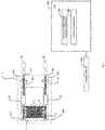
- a temperature management apparatus includes a temperature-controlled furnace 1 that has a temperature-controlled space in which an article 5 is disposed, rod-shaped members 2A and 2B that include magnetic materials, opposite members 3A and 3B that are opposed to parts of side surfaces of the rod-shaped members 2A and 2B respectively and include magnetic materials, a driving device 4A that rotates the rod-shaped member 2A about a central axis to change a relative position between the rod-shaped member 2A and the opposite member 3A, a driving device 4B that rotates the rod-shaped member 2B about a central axis to change a relative position between the rod-shaped member 2B and the opposite member 3B, and a synchronization loss monitoring portion 301 that predicts or detects synchronization losses of the rod-shaped members 2A and 2B and the opposite members 3A and 3B respectively based on fluctuations of torques of the driving devices 4A and 4B.
- the synchronization loss monitoring portion 301 is included in, for example,
- the temperature-controlled furnace 1 is, for example, a freeze drying furnace.
- a shelf board 7 is disposed in the temperature-controlled furnace 1 and the article 5 including an object to be freeze-dried is disposed on the shelf board 7.
- the article 5 is, for example, a vial into which a medicine has been poured.
- the cylindrical rod-shaped member 2A is held in the temperature-controlled furnace 1 by bearings 12A and 13A.
- the rod-shaped member 2A is a magnetic screw including a hard magnetic material and S pole magnetized zones and N pole magnetized zones are alternately provided on an outer peripheral surface thereof in a spiral shape.
- the rod-shaped member 2A may be inserted into a thin-walled pipe 20A made of a nonmagnetic material.
- the pipe 20A is made of, for example, stainless steel.
- the rod-shaped member 2A and the pipe 20A are integrated with each other and, when the rod-shaped member 2A rotates, the pipe 20A also rotates about the central axis of the rod-shaped member 2A.
- the opposite member 3A held in the temperature-controlled furnace 1 is a magnetic nut including a hard magnetic material and is provided with a hole having an inner circumference larger than an outer circumference of the rod-shaped member 2A.
- the rod-shaped member 2A penetrates through the hole of the nut-shaped opposite member 3A.
- S pole magnetized zones and N pole magnetized zones are alternately provided in a spiral shape on an inner peripheral surface of the hole of the opposite member 3A.
- the pitch of the magnetized zones in the opposite member 3A is substantially the same as the pitch of the magnetized zones in the rod-shaped member 2A.
- Guide rings 31 and 32 such as bushes may be disposed on an inner peripheral surface of the opposite member 3A.
- the inner circumferences of the guide rings 31 and 32 are smaller than the inner circumference of the opposite member 3A and make contact with an outer peripheral surface of the pipe 20A. As a result, a constant interval is kept between the magnetized zones of the rod-shaped member 2A and the magnetized zones of the opposite member 3A.
- the guide rings 31 and 32 are made of materials having a small friction coefficient, such as fluororesin.
- the cylindrical rod-shaped member 2B is held in parallel with the rod-shaped member 2A by bearings 12B and 13B in the temperature-controlled furnace 1.
- the structure of the rod-shaped member 2B is the same as that of the rod-shaped member 2A.
- the structure of the opposite member 3B held in the temperature-controlled furnace 1 is the same as that of the opposite member 3A.
- the temperature management apparatus further includes a contact member 6 that moves within the temperature-controlled furnace 1 with changes in the relative positions between, for example, the rod-shaped members 2A and 2B and the opposite members 3A and 3B and moves the article 5 by making contact with the article 5.
- the contact member 6 held in the temperature-controlled furnace 1 is a plate member and is fixed between the opposite member 3A and the opposite member 3B so as to be substantially perpendicular to a surface of the shelf board 7.
- the driving devices 4A and 4B include rotating motors and are disposed outside the temperature-controlled space of the temperature-controlled furnace 1.
- the driving devices 4A and 4B may be disposed outside the casing of the temperature-controlled furnace 1 or may be disposed outside the temperature-controlled space in the casing of the temperature-controlled furnace 1.
- the driving devices 4A and 4B may be covered with a shield or the like that prevents diffusion of dust that may be generated or the like.
- the driving device 4A and the rod-shaped member 2A are connected to each other via, for example, a mandrel 11A that penetrates through a side wall of the temperature-controlled furnace 1.
- the disposition of the driving device 4A is fixed and the rod-shaped member 2A connected to the driving device 4A cannot move in the direction of the central axis thereof.
- the driving device 4B and the rod-shaped member 2B are connected to each other via, for example, a mandrel 11B that penetrates through the side wall of the temperature-controlled furnace 1.
- the disposition of the driving device 4B is fixed and the rod-shaped member 2B connected to the driving device 4B cannot move in the direction of the central axis thereof.
- Holes of the side wall of the temperature-controlled furnace 1 through which the mandrels 11A and 11B penetrate are provided with sealing members such as, for example, oil seals.
- the driving devices 4A and 4B rotate the rod-shaped members 2A and 2B in synchronization with each other.
- a magnetic force acts between the magnetized zones of the rod-shaped member 2A and the magnetized zones of the opposite member 3A.
- the opposite member 3A is fixed to the contact member 6 and the opposite member 3B and cannot rotate. Therefore, when the rod-shaped member 2A is rotated, the opposite member 3A moves along the central axis of the rod-shaped member 2A.
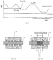
- the torque of the driving device 4A is reduced and the driving current for the driving device 4A is reduced as illustrated in Fig. 3 .
- the torque of the driving device 4B is reduced and the driving current for the driving device 4B is reduced. Since the driving current has a correlation with the torque, the measurement value of the driving current can be used as a measurement value representing the torque.
- the synchronization loss monitoring portion 301 detects fluctuations in the torques based on changes in the driving currents for the driving devices 4A and 4B with respect to the time axis. It should be noted here that the synchronization loss monitoring portion 301 may monitor fluctuations in the driving currents for the driving devices 4A and 4B by monitoring the driving voltages for the driving devices 4A and 4B.
- the synchronization loss monitoring portion 301 predicts that a synchronization loss of the opposite member 3A with respect to the rod-shaped member 2A possibly occurs when, for example, the driving current for the driving device 4A is equal to or less than a first current threshold. In addition, the synchronization loss monitoring portion 301 decides that a synchronization loss of the opposite member 3A with respect to the rod-shaped member 2A has occurred when the driving current for the driving device 4A is equal to or less than a second current threshold that is less than the first current threshold. Similarly, the synchronization loss monitoring portion 301 predicts that a synchronization loss of the opposite member 3B with respect to the rod-shaped member 2B possibly occurs when the driving current for the driving device 4B is equal to or less than the first current threshold. In addition, the synchronization loss monitoring portion 301 decides that a synchronization loss of the opposite member 3B with respect to the rod-shaped member 2B has occurred when the driving current for the driving device 4B is equal to or less than the second current threshold.
- the synchronization loss monitoring portion 301 may calculate the torques based on the driving currents for the driving devices 4A and 4B. In this case, the synchronization loss monitoring portion 301 predicts that a synchronization loss of the opposite member 3A with respect to the rod-shaped member 2A possibly occurs when the torque of the driving device 4A is equal to or less than a first torque threshold. In addition, the synchronization loss monitoring portion 301 decides that a synchronization loss of the opposite member 3A with respect to the rod-shaped member 2A has occurred when the torque of the driving device 4A is equal to or less than a second torque threshold that is less than the first torque threshold.
- the synchronization loss monitoring portion 301 predicts that a synchronization loss of the opposite member 3B with respect to the rod-shaped member 2B possibly occurs when the torque of the driving device 4B is equal to or less than the first torque threshold. In addition, the synchronization loss monitoring portion 301 decides that a synchronization loss of the opposite member 3B with respect to the rod-shaped member 2B has occurred when the torque of the driving device 4B is equal to or less than the second torque threshold.
- the synchronization loss monitoring portion 301 may calculate a torque derivative value by differentiating measurement values representing the torques of the driving devices 4A and 4B by time and may predict or detect a synchronization loss based on the waveform of the torque derivative value on the time axis or the like.
- the torque derivative value is substantially constant with respect to the time axis when a synchronization loss does not occur, but the torque derivative value is reduced, reaches a negative peak, is increased, and reaches a positive peak with respect to the time axis when a synchronization loss occurs.
- the synchronization loss monitoring portion 301 illustrated in Fig. 1 predicts that a synchronization loss of the opposite member 3A with respect to the rod-shaped member 2A possibly occurs when the torque derivative value of the driving device 4A becomes equal to or less than a first negative derivative threshold and then becomes equal to or more than a first positive derivative threshold within a predetermined time range.
- the synchronization loss monitoring portion 301 decides that a synchronization loss of the opposite member 3A with respect to the rod-shaped member 2A has occurred when the torque derivative value of the driving device 4A becomes equal to or less than a second negative derivative threshold that is less than the first negative derivative threshold and then becomes equal to or more than a second positive derivative threshold that is more than the first positive derivative threshold.
- the synchronization loss monitoring portion 301 predicts that a synchronization loss of the opposite member 3B with respect to the rod-shaped member 2B possibly occurs when the torque derivative value of the driving device 4B becomes equal to or less than the first negative derivative threshold and then becomes equal to or more than the first positive derivative threshold within a predetermined time range. In addition, the synchronization loss monitoring portion 301 decides that a synchronization loss of the opposite member 3B with respect to the rod-shaped member 2B has occurred when the torque derivative value of the driving device 4B becomes equal to or less than the second negative derivative threshold and then becomes equal to or more than the second positive derivative threshold.
- the synchronization loss monitoring portion 301 may calculate a torque integral value by integrating measurement values representing the torques of the driving devices 4A and 4B by time and may predict or detect a synchronization loss based on the waveform of the torque integral value on the time axis or the like.
- the torque integral value is substantially constant with respect to the time axis when a synchronization loss does not occur, but the torque integral value is increased and reaches a positive peak with respect to the time axis when a synchronization loss occurs.
- the synchronization loss monitoring portion 301 predicts that a synchronization loss of the opposite member 3A with respect to the rod-shaped member 2A possibly occurs when the torque integral value of the driving device 4A is equal to or more than a first integral threshold. In addition, the synchronization loss monitoring portion 301 decides that a synchronization loss of the opposite member 3A with respect to the rod-shaped member 2A has occurred when the torque integral value of the driving device 4A is equal to or more than a second torque integral threshold that is more than the first torque integral threshold.
- the synchronization loss monitoring portion 301 predicts that a synchronization loss of the opposite member 3B with respect to the rod-shaped member 2B possibly occurs when the torque integral value of the driving device 4B is equal to or less than the first integral threshold. In addition, the synchronization loss monitoring portion 301 decides that a synchronization loss of the opposite member 3B with respect to the rod-shaped member 2B has occurred when the torque integral value of the driving device 4B is equal to or more than the second integral threshold.
- the synchronization loss monitoring portion 301 does not need to decide the occurrence of a synchronization loss immediately after the driving devices 4A and 4B start rotation and immediately before the driving devices 4A and 4B stop.
- the CPU 300 further includes a controlling portion 302 that controls the driving devices 4A and 4B. For example, when the synchronization loss monitoring portion 301 has predicted or detected a synchronization loss, the controlling portion 302 stops the driving devices 4A and 4B.
- a memory device 401 is connected to the CPU 300.
- the memory device 401 stores the first and second current thresholds, the first and second torque thresholds, the first and second positive derivative thresholds, the first and second negative derivative thresholds, or the first and second integral thresholds.
- the synchronization loss monitoring portion 301 reads first and second thresholds from the memory device 401.
- the first and second thresholds are set to predetermined values in advance.
- the first and second thresholds may be calculated by a simulation or the like.
- a driving force is transmitted between the rod-shaped members 2A and 2B and the opposite members 3A and 3B in a non-contact manner by a magnetic force. Accordingly, when a driving force is transmitted between the rod-shaped members 2A and 2B and the opposite members 3A and 3B, heat and dust are unlikely to be generated. Therefore, even if the rod-shaped members 2A and 2B and the opposite members 3A and 3B are disposed in the temperature-controlled space of the temperature-controlled furnace 1, an influence of heat generation in the temperature-controlled space can be suppressed and the temperature-controlled space can be kept clean.
- the driving devices 4A and 4B are disposed outside the temperature-controlled space of the temperature-controlled furnace 1, even if dust is generated in the driving devices 4A and 4B, the dust is unlikely to enter the temperature-controlled space of the temperature-controlled furnace 1.
- a temperature distribution may become uneven inside the temperature-controlled furnace such as a freeze drying furnace due to the heated driving device. In this case, the quality of a plurality of articles disposed in the temperature-controlled furnace may become uneven.
- the temperature management apparatus since the driving devices 4A and 4B are disposed outside the temperature-controlled space of the temperature-controlled furnace 1, the temperature is unlikely to become uneven inside the temperature-controlled furnace 1.
- the temperature management apparatus when the contact member 6 is moved, the rod-shaped members 2A and 2B do not go out of the temperature-controlled furnace 1. Therefore, no foreign matters are drawn into the temperature-controlled furnace 1 by the rod-shaped members 2A and 2B from the outside of the temperature-controlled furnace 1. Accordingly, the temperature management apparatus according to the first embodiment can keep the inside of the temperature-controlled furnace 1 clean and suppress the temperature unevenness in the temperature-controlled furnace 1.
- the temperature management apparatus can predict or detect synchronization losses of the rod-shaped members 2A and 2B and the opposite members 3A and 3B, respectively. Therefore, it is possible to prevent the article 5 from being disposed inaccurately or the device from failing due to a synchronization loss.
- the temperature management apparatus can detect torques without disposing sensors in the rod-shaped members 2A and 2B and the opposite members 3A and 3B.
- the rod-shaped member 2A and the opposite member 3A are not limited to the example illustrated in Fig. 2 .
- the rod-shaped member 2A may be formed of a threaded soft magnetic material.
- the structure of the opposite member 3A is the same as that in Fig. 2 .
- the pitch of the threads of the rod-shaped member 2A illustrated in Fig. 5 is substantially the same as the pitch of the magnetized zones of the opposite member 3A.
- the threaded rod-shaped member 2A may be inserted into the thin-walled pipe 20A made of a nonmagnetic material. This can prevent foreign matters from adhering to the threaded groove of the rod-shaped member 2A.
- a magnetic force acts between the threads of the rod-shaped member 2A and the magnetized zones of the opposite member 3A and the opposite member 3A moves.
- the opposite member 3A may be formed of a threaded soft magnetic material.
- the surface of a threaded hole in the opposite member 3A may be covered with a thin-walled pipe 30A made of a nonmagnetic material. This can prevent foreign matters from adhering to the threaded groove of the opposite member 3A.
- the structure of the rod-shaped member 2A is the same as that in Fig. 2 .
- the pitch of the threads of the opposite member 3A illustrated in Fig. 6 is substantially the same as the pitch of the magnetized zones of the rod-shaped member 2A.
- the rod-shaped member 2B and the opposite member 3B illustrated in Fig. 1 may also have structures as illustrated in Fig. 5 or 6 .
- a temperature management apparatus includes a temperature-controlled furnace 1 in which an article 5 is stored, rod-shaped members 102A and 102B that include magnetic materials, opposite members 103A and 103B that are opposed to parts of side surfaces of the rod-shaped members 102A and 102B respectively and include magnetic materials, a driving device 104A that rotates the opposite member 103A about a central axis of the rod-shaped member 102A to change a relative position between the rod-shaped member 102A and the opposite member 103A, a driving device 104B that rotates the opposite member 103B about a central axis of the rod-shaped member 102B to change a relative position between the rod-shaped member 102B and the opposite member 103B, and a synchronization loss monitoring portion 301 that predicts or detects synchronization losses of the rod-shaped members 102A and 102B and the opposite members 103A and 103B respectively based on fluctuations of torques of the driving devices
- the driving device 104A disposed outside a temperature-controlled space of the temperature-controlled furnace 1 rotates the opposite member 103A disposed outside the temperature-controlled space of the temperature-controlled furnace 1 via a belt 134A or the like.
- the disposition of the driving device 104A is fixed and the opposite member 103A cannot move in a direction of the central axis of the rod-shaped member 102A.
- the driving device 104B disposed outside the temperature-controlled space of the temperature control furnace 1 rotates the opposite member 103B disposed outside the temperature-controlled space of the temperature-controlled furnace 1 via a belt 134B or the like.
- the disposition of the driving device 104B is fixed and the opposite member 103B cannot move in the direction of the central axis of the rod-shaped member 102B.
- the driving devices 104A and 104B and the belts 134A and 134B may be covered with a shield or the like that prevents diffusion of dust that may be generated or the like.
- the rod-shaped members 102A and 102B are held so as to be movable in the directions of the central axes thereof.
- a contact member 106 is fixed to end portions of the rod-shaped members 102A and 102B.
- the rod-shaped members 102A and 102B project to the outside of the temperature-controlled furnace 1 through a side wall of the temperature-controlled furnace 1. Holes of the side wall of the temperature-controlled furnace 1 through which the rod-shaped members 102A and 102B penetrate are provided with sealing members such as, for example, oil seals.
- the parts of the rod-shaped members 102A and 102B projecting to the outside of the temperature-controlled furnace 1 penetrate through holes of the nut-shaped opposite members 103A and 103B. Since the rod-shaped members 102A and 102B are fixed to the contact member 106, the rod-shaped members 102A and 102B cannot rotate about the central axes thereof.
- the driving devices 104A and 104B synchronously rotate the opposite members 103A and 103B.
- the driving device 104A rotates the opposite member 103A
- the rod-shaped member 102A is moved along the central axis thereof by a magnetic force.
- the driving device 104B rotates the opposite member 103B
- the rod-shaped member 102B is moved along the central axis thereof by a magnetic force.
- the contact member 106 fixed between the rod-shaped members 102A and 102B also moves on a shelf board 7 along the central axes of the rod-shaped members 102A and 102B with the movement of the rod-shaped members 102A and 102B.
- the article 5 disposed on the shelf board 7 moves on the shelf board 7 by being pushed by the contact member 6.
- the synchronization loss monitoring portion 301 predicts or detects a synchronization loss as in the first embodiment.
- a controlling portion 302 stops the driving devices 104A and 104B.
- a driving force is transmitted between the rod-shaped members 102A and 102B and the opposite members 103A and 103B in a non-contact manner by a magnetic force. Accordingly, when a driving force is transmitted between the rod-shaped members 102A and 102B and the opposite members 103A and 103B, heat and dust are unlikely to be generated. Therefore, even when the rod-shaped members 102A and 102B and the opposite members 103A and 103B are disposed in, for example, a clean room, the influence of heat generation in the clean room can be suppressed and the clean room can be kept clean.
- the temperature management apparatus according to the second embodiment since the rod-shaped members 102A and 102B do not rotate, there is no need to install the bearings and the like in the temperature-controlled furnace 1. Accordingly, the temperature management apparatus according to the second embodiment can keep the inside of the temperature-controlled furnace 1 clean and suppress the temperature unevenness in the temperature-controlled furnace 1.
- the temperature management apparatus according to the second embodiment can predict or detect synchronization losses of the rod-shaped members 102A and 102B and the opposite members 103A and 103B, respectively. Therefore, it is possible to prevent the article 5 from being disposed inaccurately or the device from failing due to a synchronization loss.
- the temperature management apparatus according to the second embodiment can detect torques without disposing sensors in the rod-shaped members 102A and 102B and the opposite members 103A and 103B.
- a temperature management apparatus has a structure similar to the temperature management apparatus according to the first embodiment illustrated in Fig. 1 .
- a load F r (N) applied to each of the opposite members 3A and 3B exceeds the maximum value (maximum generable thrust force) F max (N) of a thrust force that can be generated by a magnetic coupling
- a synchronization loss occurs.
- a load F 1 is applied to each of the opposite members 3A and 3B and the load F 1 is less than the maximum generable thrust force F max in the example illustrated in Fig. 8
- a synchronization loss does not occur.
- a load F 2 is applied to each of the opposite members 3A and 3B and the load F 2 exceeds the maximum generable thrust force F max , a synchronization loss occurs.
- the synchronization loss monitoring portion 301 illustrated in Fig. 1 has a logic circuit that monitors the load F r applied to the opposite member 3A and the maximum generable thrust force F max by a magnetic coupling between the opposite member 3A and the rod-shaped member 2A during operation of the driving device 4A and stops the driving device 4A before the load F r exceeds the maximum generable thrust force F max .
- the synchronization loss monitoring portion 301 also monitors the combination of the opposite member 3B and the rod-shaped member 2B similarly and stops the driving device 4B before the load F r exceeds the maximum generable thrust force F max . This can prevent a synchronization loss from occurring.
- the combination of the opposite member 3A and the rod-shaped member 2A will be described below, this is also true of the combination of the opposite member 3B and the rod-shaped member 2B.
- the number of magnetic couplings generated between the opposite member 3A and the rod-shaped member 2A is proportional to the thrust force. Therefore, the maximum generable thrust force F max can be obtained in advance by an experiment and/or an analysis. For example, in Fig. 9(a) , six pairs of S pole and N pole magnetized zones of the opposite member 3A are magnetically coupled to the threads of the rod-shaped member 2A made of a soft magnetic material. In contrast, in Fig. 9(b) , since a coupler 22A is provided in the joint of the rod-shaped members 2A, four pairs of S pole and N pole magnetized zones of the opposite member 3A are magnetically coupled with the threads of the rod-shaped members 2A made of a soft magnetic material. Accordingly, the maximum generable thrust force F max in the state illustrated in Fig. 9(b) is smaller than the maximum generable thrust force F max in the state illustrated in Fig. 9(a) .
- the memory device 401 illustrated in Fig. 1 stores the relationship between the position of the opposite member 3A with respect to the rod-shaped member 2A and the maximum generable thrust force F max having been obtained in advance.
- ⁇ M Rotation angle of driving device 4A (rod-shaped member 2A) (rad) x n : Displacement of opposite member 3A (m)
- J M Inertial moment of driving device 4A (rod-shaped member 2A) (kg ⁇ m 2 ) M n : Mass of opposite member 3A (kg)
- D M Viscosity friction coefficient of driving device 4A (rod-shaped member 2A) (N ⁇ m ⁇ s/rad)
- C n Viscosity friction coefficient of guide 33A for guiding opposite member 3A (N ⁇ s/m)
- N Rotation to linear motion conversion coefficient (m/rad)
- K n Stiffness in axial direction (N/m)
- F r Load F r applied to opposite member 3A (N)
- expression (2) above can be replaced with the determinant represented by expression (8) below based on expressions (3) to (7) above.
- [Math. 3] J M 0 0 M n ⁇ ⁇ M x ⁇ n + D M 0 0 C n ⁇ ⁇ M x ⁇ n + N 2 K n ⁇ NK n ⁇ NK n K n ⁇ M x n T M ⁇ T c F r
- s ⁇ M T M ⁇ T C ⁇ NK n N ⁇ M ⁇ x n J M s + D M
- x n F r + NK n ⁇ M M n s 2 + C n s + K n
- FIG. 11 A block diagram illustrating a two-inertia system dynamic model is illustrated in Fig. 11 .
- the part surrounded by a frame 201 corresponds to expression (13) above and the part surrounded by a frame 202 corresponds to expression (14) above.
- x M represents the position of the rod-shaped member 2A.
- the position x M of the rod-shaped member 2A can be detected by detecting the rotational angle ⁇ M of the driving device 4A (rod-shaped member 2A) using a rotary encoder or the like.
- K n (N ⁇ M - x n ) represents the elastic force caused by the positional deviation between the rod-shaped member 2A and the opposite member 3A.
- the synchronization loss monitoring portion 301 illustrated in Fig. 1 calculates an external force F O applied to the opposite member 3A from the driving device 4A based on the torque T M applied to the rod-shaped member 2A and the rotational angle ⁇ M of the rod-shaped member 2A, as illustrated in Fig. 12 .
- the external force F O is equivalent to the elastic force caused by the positional deviation between the rod-shaped member 2A and the opposite member 3A, as indicated in expression (15) below.
- the torque T M of the driving device 4A can be calculated based on a driving current (torque instruction current) value I ref for the driving device 4A.
- the torque T M of the driving device 4A may be a value processed by a low-pass filter 501 for removing noise in a motor current.
- the rotational angle ⁇ M of the driving device 4A (rod-shaped member 2A) can be detected by a rotary encoder or the like.
- the rotational angle ⁇ M can be calculated based on an instruction value of the rotational angle transmitted to the driving device 4A.
- the torque T C applied constantly, the inertia moment J M of the driving device 4A (rod-shaped member 2A), the viscosity friction coefficient D M of the driving device 4A (rod-shaped member 2A), and the rotational motion to linear motion conversion coefficient N may be obtained in advance and may be stored in the memory device 401 in advance.
- the synchronization loss monitoring portion 301 illustrated in Fig. 1 calculates a force Fp required to move the opposite member 3A when the load F r is not applied to the opposite member 3A based on the position x n of the opposite member 3A, as illustrated in Fig. 12 .
- the mass M n of the opposite member 3A, the viscosity friction coefficient C n of a guide 33A, and the axial direction stiffness K n can be obtained in advance and may be stored in the memory device 401 in advance.
- the position x n of the opposite member 3A can be detected by a linear encoder such as, for example, a laser displacement gauge.
- the position x n of the opposite member 3A is calculated by correcting the estimated value of the position x n based on the position x M of the rod-shaped member 2A.
- the initial value of the estimated value of the position x n may be any value, so it may be assumed to be, for example, 0 or a position x M res of the rod-shaped member 2A.
- X M res N ⁇ M res in expression (18).
- the synchronization loss monitoring portion 302 calculates the error e again based on expression (18) above using the estimated value of the position x n corrected by expression (19) above. After that, the synchronization loss monitoring portion 302 repeats the calculation of expression (18) and expression (19) above until the absolute value of the calculated error e is less than a predetermined threshold.
- the synchronization loss monitoring portion 302 uses the estimated value of the position x n when the absolute value of the calculated error e becomes less than the predetermined threshold as the position x n of the opposite member 3A.
- the part surrounded by a frame 203 in Fig. 12 has the function of correcting the estimated value of the position x n based on the position x M of the rod-shaped member 2A.
- the synchronization loss monitoring portion 301 illustrated in Fig. 1 calculates the load F r applied to the opposite member 3A based on the difference between the external force F O applied to the opposite member 3A from the driving device 4A via the rod-shaped member 2A and the force F P required to move only the opposite member 3A, as illustrated in Fig. 12 .
- the synchronization loss monitoring portion 301 illustrated in Fig. 1 compares the load F r applied to the opposite member 3A with the maximum generable thrust force F max according to the position of the opposite member 3A and monitors whether the load F r is less than the maximum generable thrust force F max , as indicated by expression (20) below.
- the controlling portion 302 stops the driving device 4A.
- the synchronization loss monitoring portion 301 illustrated in Fig. 1 compares the torque value at the current time with a reference value using a past torque value of the driving device 4A as the reference value and decides that a synchronization loss has not occurred when the difference between the current torque value and the reference value is less than a predetermined threshold or decides that a synchronization loss has occurred when the difference is more than the predetermined threshold.
- ⁇ i 1 k T i ⁇ T t
- the synchronization loss monitoring portion 301 illustrated in Fig. 1 may assume the number of times the difference has exceeded the predetermined threshold to be the number of times the synchronization loss has occurred. It should be noted here that the reference value of the torque may be the average value.
- the articles transferred to or from the temperature-controlled furnace are not limited to the inclusion of medicines, but may include foods, beverages, precision parts, etc., as well as any articles to be controlled in temperature.
- the temperature-controlled furnace of the temperature management apparatus is not limited to the freeze drying furnace and may be a fermentation furnace or includes any furnace in which the suppression of the internal temperature distribution unevenness and the suppression of the dust generation are desired.
- the shape of the opposite members is not limited to the nut shape, but may be, for example, a concave shape.
- the rod-shaped member passes through a concave portion of a concave opposite member.
- S pole magnetized zones and N pole magnetized zones are alternately provided on the side surface of the concave portion of the concave opposite member.
Landscapes
- Physics & Mathematics (AREA)
- General Physics & Mathematics (AREA)
- Engineering & Computer Science (AREA)
- Power Engineering (AREA)
- Monitoring And Testing Of Nuclear Reactors (AREA)
- Control Of Conveyors (AREA)
- Non-Mechanical Conveyors (AREA)
- Warehouses Or Storage Devices (AREA)
Abstract
Description
- The present invention relates to a transfer technique.
- Since magnetic screws are driven by non-contact coupling using a magnetic force, application of an overload easily tends to cause a synchronization loss between a male magnetic screw and a female magnetic screw. When a synchronization loss is caused in magnetic screws in which a male magnetic screw is rotationally driven, a deviation occurs in coupling between a rotation command for the male magnetic screw and the actual movement position of a female magnetic screw that is a nut and synchronous driving may be disabled. In this case, a positioning failure or an overrun of the nut may be caused. Therefore, it is preferable to predict or detect a synchronization loss when using magnetic screws.
PTL 1 discloses a device that detects changes in a magnetic flux due to a synchronization loss by installing a magnetic sensor on a nut. - PTL 1: Japanese Patent No.
3610209 - One object of the invention is to provide a transfer apparatus capable of predicting or detecting a synchronization loss without detecting changes in a magnetic flux with a magnetic sensor.
- According to an aspect of the invention, there is provided a temperature management apparatus including (a) a temperature-controlled furnace that has a temperature-controlled space in which an article is disposed, (b) a rod-shaped member that includes a magnetic material; (c) an opposite member that is opposed to a part of a side surface of the rod-shaped member and includes a magnetic material; (d) a driving device configured to rotate the rod-shaped member or the opposite member about a central axis of the rod-shaped member to change a relative position between the rod-shaped member and the opposite member; and (e) a synchronization loss monitoring portion configured to predict or detect a synchronization loss between the rod-shaped member and the opposite member based on a fluctuation of a torque of the driving device.
- The temperature management apparatus described above may further include a controlling portion configured to control the driving device when the synchronization loss has been predicted or detected.
- In the temperature management apparatus described above, the synchronization loss monitoring portion may be configured to detect the fluctuation of the torque based on a fluctuation of a driving current for the driving device.
- In the temperature management apparatus described above, the synchronization loss monitoring portion may be configured to differentiate a measurement value representing the torque. Alternatively, the synchronization loss monitoring portion may be configured to integrate a measurement value representing the torque.
- In the temperature management apparatus described above, the driving device may be configured to rotate the rod-shaped member about the central axis of the rod-shaped member and the synchronization loss monitoring portion may be configured to calculate a load applied to the opposite member based on a difference between an external force applied to the opposite member by the driving device via the rod-shaped member and a force required to move the opposite member when no load is applied to the opposite member and predict or detect the synchronization loss based on the calculated load.
- In the temperature management apparatus described above, the external force applied to the opposite member by the driving device via the rod-shaped member may be calculated based on the torque of the driving device.
- In the temperature management apparatus described above, the force required to move the opposite member when no load is applied to the opposite member may be calculated based on a position of the opposite member.
- In the temperature management apparatus described above, the synchronization loss monitoring portion may be configured to predict or detect the synchronization loss by comparing a maximum value of a thrust force generated by a magnetic coupling between the rod-shaped member and the opposite member with the load.
- The temperature management apparatus described above may further include a memory device that stores a relationship between the position of the opposite member and the maximum value of the thrust force.
- In the temperature management apparatus described above, the synchronization loss monitoring portion may be configured to compare a difference between a reference value representing the torque of the driving device and a measurement value representing the torque of the driving device with a predetermined threshold.
- In the temperature management apparatus described above, the difference between the reference value representing the torque of the driving device and the measurement value representing the torque of the driving device may be an average value.
- In the temperature management apparatus described above, the synchronization loss monitoring portion may be configured to assume the number of times the difference between the reference value representing the torque of the driving device and the measurement value representing the torque of the driving device has exceeded the predetermined threshold to be the number of times the synchronization loss has occurred.
- The temperature management apparatus described above may further include a contact member configured to move within the temperature-controlled furnace with a change in the relative position between the rod-shaped member and the opposite member and moves an article by making contact with the article.
- In the temperature management apparatus described above, the driving device may be disposed outside the temperature-controlled space.
- In the temperature management apparatus described above, when the driving device rotates the rod-shaped member, the opposite member may move along the central axis of the rod-shaped member and the contact member fixed to the opposite member may move. In this case, the rod-shaped member, the opposite member, and the contact member may be disposed in the temperature-controlled space. The temperature management apparatus described above may further include a mandrel that penetrates through a side wall of the temperature-controlled furnace and makes connection between the rod-shaped member and the driving device. In addition, the temperature management apparatus may further include a sealing member provided in a hole of the side wall of the temperature-controlled furnace through which the mandrel penetrates.
- In the temperature management apparatus described above, when the driving device rotates the opposite member, the rod-shaped member may move in a direction of the central axis and the contact member fixed to the rod-shaped member may move. In this case, the contact member may be disposed in the temperature-controlled space and the opposite member may be disposed outside the temperature-controlled space. The rod-shaped member may penetrate through the side wall of the temperature-controlled furnace. The temperature management apparatus may further include a sealing member provided in a hole of the side wall of the temperature-controlled furnace through which the rod-shaped member penetrates.
- In the temperature management apparatus described above, the temperature-controlled furnace may be a freeze drying furnace. The article may include a medicine.
- According to an aspect of the invention, there is provided a transfer apparatus including (a) a rod-shaped member that includes a magnetic material; (b) an opposite member that is opposed to a part of a side surface of the rod-shaped member and includes a magnetic material; (c) a driving device configured to rotate the rod-shaped member or the opposite member about a central axis of the rod-shaped member to change a relative position between the rod-shaped member and the opposite member; and (d) a synchronization loss monitoring portion configured to predict or detect a synchronization loss between the rod-shaped member and the opposite member based on a fluctuation of a torque of the driving device.
- The transfer apparatus described above may further include a controlling portion configured to control the driving device when the synchronization loss has been predicted or detected.
- In the transfer apparatus described above, the synchronization loss monitoring portion may be configured to detect the fluctuation of the torque based on a fluctuation of a driving current for the driving device.
- In the transfer apparatus described above, the synchronization loss monitoring portion may be configured to differentiate a measurement value representing the torque. Alternatively, the synchronization loss monitoring portion may be configured to integrate a measurement value representing the torque.
- In the transfer apparatus described above, when the driving device rotates the rod-shaped member, the opposite member may move along the central axis of the rod-shaped member. Alternatively, when the driving device rotates the opposite member, the rod-shaped member may move in a direction of the central axis.
- In the transfer apparatus described above, the driving device may be configured to rotate the rod-shaped member about the central axis of the rod-shaped member and the synchronization loss monitoring portion may be configured to calculate a load applied to the opposite member based on a difference between an external force applied to the opposite member by the driving device via the rod-shaped member and a force required to move the opposite member when no load is applied to the opposite member and predict or detect the synchronization loss based on the calculated load.
- In the transfer apparatus described above, the external force applied to the opposite member by the driving device via the rod-shaped member may be calculated based on the torque of the driving device.
- In the transfer apparatus described above, the force required to move the opposite member when no load is applied to the opposite member may be calculated based on a position of the opposite member.
- In the transfer apparatus described above, the synchronization loss monitoring portion may be configured to predict or detect the synchronization loss by comparing a maximum value of a thrust force generated by a magnetic coupling between the rod-shaped member and the opposite member with the load.
- The transfer apparatus described above may further include a memory device configured to store a relationship between the position of the opposite member and the maximum value of the thrust force.
- In the transfer apparatus described above, the synchronization loss monitoring portion may be configured to compare a difference between a reference value representing the torque of the driving device and a measurement value representing the torque of the driving device with a predetermined threshold.
- In the transfer apparatus described above, the difference between the reference value representing the torque of the driving device and the measurement value representing the torque of the driving device may be an average value.
- In the transfer apparatus described above, the synchronization loss monitoring portion may be configured to assume the number of times the difference between the reference value representing the torque of the driving device and the measurement value representing the torque of the driving device has exceeded the predetermined threshold to be the number of times the synchronization loss has occurred.
- According to the invention, it is possible to provide a transfer apparatus capable of predicting or detecting a synchronization loss without detecting a change in a magnetic flux with a magnetic sensor.
-
-
Fig. 1 is a schematic view illustrating a temperature management apparatus according to a first embodiment. -
Fig. 2 is a schematic view illustrating a rod-shaped member and an opposite member according to the first embodiment. -
Fig. 3 is a graph illustrating temporal changes of a torque according to the first embodiment. -
Fig. 4 is a graph illustrating temporal changes of a derivative value of the torque according to the first embodiment. -
Fig. 5 is a schematic view illustrating a rod-shaped member and an opposite member according to a modification of the first embodiment. -
Fig. 6 is a schematic view illustrating a rod-shaped member and an opposite member according to a modification of the first embodiment. -
Fig. 7 is a schematic view illustrating a temperature management apparatus according to a second embodiment. -
Fig. 8 is a graph illustrating the relationship between a thrust force and a load applied to an opposite member according to a third embodiment. -
Fig. 9 is a schematic view illustrating a rod-shaped member and the opposite member according to the third embodiment. -
Fig. 10 is a two-inertia system dynamic model of a system including a driving device, the rod-shaped member, and the opposite member according to the third embodiment. -
Fig. 11 is a block diagram illustrating the two-inertia system dynamic model according to the third embodiment. -
Fig. 12 is a block diagram illustrating the two-inertia system dynamic model according to the third embodiment. -
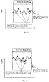
Fig. 13 is a graph used to describe k-nearest neighbor algorithm according to a fourth embodiment. -
Fig. 14 is a graph used to describe k-nearest neighbor algorithm according to the fourth embodiment. -
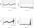
Fig. 15 is a graph used to describe the difference between a reference value and a torque at the current time according to the fourth embodiment. -
Fig. 16 is a graph used to describe the difference between the reference value and the torque at the current time according to the fourth embodiment. - Embodiments of the invention will be described below. In the description of the drawings given below, the same or similar parts are denoted by the same or similar reference numerals. However, the drawings are illustrated schematically. Accordingly, specific dimensions and the like should be decided with reference to the following description. It will be appreciated that the relationship or the ratio between dimensions may be different among the drawings.
- As illustrated in
Fig. 1 , a temperature management apparatus according to a first embodiment includes a temperature-controlledfurnace 1 that has a temperature-controlled space in which anarticle 5 is disposed, rod-shapedmembers 2A and 2B that include magnetic materials,opposite members members 2A and 2B respectively and include magnetic materials, adriving device 4A that rotates the rod-shapedmember 2A about a central axis to change a relative position between the rod-shapedmember 2A and theopposite member 3A, a driving device 4B that rotates the rod-shaped member 2B about a central axis to change a relative position between the rod-shaped member 2B and theopposite member 3B, and a synchronizationloss monitoring portion 301 that predicts or detects synchronization losses of the rod-shapedmembers 2A and 2B and theopposite members driving devices 4A and 4B. The synchronizationloss monitoring portion 301 is included in, for example, a central processing unit (CPU) 300. - The temperature-controlled
furnace 1 is, for example, a freeze drying furnace. For example, ashelf board 7 is disposed in the temperature-controlledfurnace 1 and thearticle 5 including an object to be freeze-dried is disposed on theshelf board 7. Thearticle 5 is, for example, a vial into which a medicine has been poured. - The cylindrical rod-shaped
member 2A is held in the temperature-controlledfurnace 1 bybearings Fig. 2 , the rod-shapedmember 2A is a magnetic screw including a hard magnetic material and S pole magnetized zones and N pole magnetized zones are alternately provided on an outer peripheral surface thereof in a spiral shape. The rod-shapedmember 2A may be inserted into a thin-walled pipe 20A made of a nonmagnetic material. Thepipe 20A is made of, for example, stainless steel. The rod-shapedmember 2A and thepipe 20A are integrated with each other and, when the rod-shapedmember 2A rotates, thepipe 20A also rotates about the central axis of the rod-shapedmember 2A. - The
opposite member 3A held in the temperature-controlledfurnace 1 is a magnetic nut including a hard magnetic material and is provided with a hole having an inner circumference larger than an outer circumference of the rod-shapedmember 2A. The rod-shapedmember 2A penetrates through the hole of the nut-shapedopposite member 3A. S pole magnetized zones and N pole magnetized zones are alternately provided in a spiral shape on an inner peripheral surface of the hole of theopposite member 3A. The pitch of the magnetized zones in theopposite member 3A is substantially the same as the pitch of the magnetized zones in the rod-shapedmember 2A. Guide rings 31 and 32 such as bushes may be disposed on an inner peripheral surface of theopposite member 3A. The inner circumferences of the guide rings 31 and 32 are smaller than the inner circumference of theopposite member 3A and make contact with an outer peripheral surface of thepipe 20A. As a result, a constant interval is kept between the magnetized zones of the rod-shapedmember 2A and the magnetized zones of theopposite member 3A. The guide rings 31 and 32 are made of materials having a small friction coefficient, such as fluororesin. - As illustrated in
Fig. 1 , the cylindrical rod-shaped member 2B is held in parallel with the rod-shapedmember 2A by bearings 12B and 13B in the temperature-controlledfurnace 1. The structure of the rod-shaped member 2B is the same as that of the rod-shapedmember 2A. The structure of theopposite member 3B held in the temperature-controlledfurnace 1 is the same as that of theopposite member 3A. - The temperature management apparatus further includes a
contact member 6 that moves within the temperature-controlledfurnace 1 with changes in the relative positions between, for example, the rod-shapedmembers 2A and 2B and theopposite members article 5 by making contact with thearticle 5. Thecontact member 6 held in the temperature-controlledfurnace 1 is a plate member and is fixed between theopposite member 3A and theopposite member 3B so as to be substantially perpendicular to a surface of theshelf board 7. - The
driving devices 4A and 4B include rotating motors and are disposed outside the temperature-controlled space of the temperature-controlledfurnace 1. Thedriving devices 4A and 4B may be disposed outside the casing of the temperature-controlledfurnace 1 or may be disposed outside the temperature-controlled space in the casing of the temperature-controlledfurnace 1. Thedriving devices 4A and 4B may be covered with a shield or the like that prevents diffusion of dust that may be generated or the like. Thedriving device 4A and the rod-shapedmember 2A are connected to each other via, for example, amandrel 11A that penetrates through a side wall of the temperature-controlledfurnace 1. The disposition of thedriving device 4A is fixed and the rod-shapedmember 2A connected to thedriving device 4A cannot move in the direction of the central axis thereof. In addition, the driving device 4B and the rod-shaped member 2B are connected to each other via, for example, a mandrel 11B that penetrates through the side wall of the temperature-controlledfurnace 1. The disposition of the driving device 4B is fixed and the rod-shaped member 2B connected to the driving device 4B cannot move in the direction of the central axis thereof. Holes of the side wall of the temperature-controlledfurnace 1 through which themandrels 11A and 11B penetrate are provided with sealing members such as, for example, oil seals. - The
driving devices 4A and 4B rotate the rod-shapedmembers 2A and 2B in synchronization with each other. When thedriving device 4A rotates the rod-shapedmember 2A, a magnetic force acts between the magnetized zones of the rod-shapedmember 2A and the magnetized zones of theopposite member 3A. Theopposite member 3A is fixed to thecontact member 6 and theopposite member 3B and cannot rotate. Therefore, when the rod-shapedmember 2A is rotated, theopposite member 3A moves along the central axis of the rod-shapedmember 2A. When the driving device 4B rotates the rod-shaped member 2B, a magnetic force acts between the magnetized zones of the rod-shaped member 2B and the magnetized zones of theopposite member 3B and theopposite member 3B moves along the central axis of the rod-shaped member 2B. Thecontact member 6 fixed between theopposite members members 2A and 2B with the movement of theopposite members shelf board 7. Thearticle 5 disposed on theshelf board 7 moves on theshelf board 7 by being pushed by thecontact member 6. Furthermore, thearticle 5 may be pushed from the door of the temperature-controlledfurnace 1 to the outside of the temperature-controlledfurnace 1. - Here, when a synchronization loss of the
opposite member 3A with respect to the rod-shapedmember 2A occurs or almost occurs, the torque of thedriving device 4A is reduced and the driving current for thedriving device 4A is reduced as illustrated inFig. 3 . In addition, when a synchronization loss of theopposite member 3B with respect to the rod-shaped member 2B illustrated inFig. 1 occurs or almost occurs, the torque of the driving device 4B is reduced and the driving current for the driving device 4B is reduced. Since the driving current has a correlation with the torque, the measurement value of the driving current can be used as a measurement value representing the torque. The synchronizationloss monitoring portion 301 detects fluctuations in the torques based on changes in the driving currents for thedriving devices 4A and 4B with respect to the time axis. It should be noted here that the synchronizationloss monitoring portion 301 may monitor fluctuations in the driving currents for thedriving devices 4A and 4B by monitoring the driving voltages for thedriving devices 4A and 4B. - The synchronization
loss monitoring portion 301 predicts that a synchronization loss of theopposite member 3A with respect to the rod-shapedmember 2A possibly occurs when, for example, the driving current for thedriving device 4A is equal to or less than a first current threshold. In addition, the synchronizationloss monitoring portion 301 decides that a synchronization loss of theopposite member 3A with respect to the rod-shapedmember 2A has occurred when the driving current for thedriving device 4A is equal to or less than a second current threshold that is less than the first current threshold. Similarly, the synchronizationloss monitoring portion 301 predicts that a synchronization loss of theopposite member 3B with respect to the rod-shaped member 2B possibly occurs when the driving current for the driving device 4B is equal to or less than the first current threshold. In addition, the synchronizationloss monitoring portion 301 decides that a synchronization loss of theopposite member 3B with respect to the rod-shaped member 2B has occurred when the driving current for the driving device 4B is equal to or less than the second current threshold. - It should be noted here that the synchronization
loss monitoring portion 301 may calculate the torques based on the driving currents for thedriving devices 4A and 4B. In this case, the synchronizationloss monitoring portion 301 predicts that a synchronization loss of theopposite member 3A with respect to the rod-shapedmember 2A possibly occurs when the torque of thedriving device 4A is equal to or less than a first torque threshold. In addition, the synchronizationloss monitoring portion 301 decides that a synchronization loss of theopposite member 3A with respect to the rod-shapedmember 2A has occurred when the torque of thedriving device 4A is equal to or less than a second torque threshold that is less than the first torque threshold. Similarly, the synchronizationloss monitoring portion 301 predicts that a synchronization loss of theopposite member 3B with respect to the rod-shaped member 2B possibly occurs when the torque of the driving device 4B is equal to or less than the first torque threshold. In addition, the synchronizationloss monitoring portion 301 decides that a synchronization loss of theopposite member 3B with respect to the rod-shaped member 2B has occurred when the torque of the driving device 4B is equal to or less than the second torque threshold. - In addition, the synchronization
loss monitoring portion 301 may calculate a torque derivative value by differentiating measurement values representing the torques of thedriving devices 4A and 4B by time and may predict or detect a synchronization loss based on the waveform of the torque derivative value on the time axis or the like. When a synchronization loss occurs, the torques of thedriving devices 4A and 4B are reduced suddenly and then returned to the original torques. Therefore, as illustrated inFig. 4 , the torque derivative value is substantially constant with respect to the time axis when a synchronization loss does not occur, but the torque derivative value is reduced, reaches a negative peak, is increased, and reaches a positive peak with respect to the time axis when a synchronization loss occurs. - Accordingly, the synchronization
loss monitoring portion 301 illustrated inFig. 1 predicts that a synchronization loss of theopposite member 3A with respect to the rod-shapedmember 2A possibly occurs when the torque derivative value of thedriving device 4A becomes equal to or less than a first negative derivative threshold and then becomes equal to or more than a first positive derivative threshold within a predetermined time range. In addition, the synchronizationloss monitoring portion 301 decides that a synchronization loss of theopposite member 3A with respect to the rod-shapedmember 2A has occurred when the torque derivative value of thedriving device 4A becomes equal to or less than a second negative derivative threshold that is less than the first negative derivative threshold and then becomes equal to or more than a second positive derivative threshold that is more than the first positive derivative threshold. - Similarly, the synchronization
loss monitoring portion 301 predicts that a synchronization loss of theopposite member 3B with respect to the rod-shaped member 2B possibly occurs when the torque derivative value of the driving device 4B becomes equal to or less than the first negative derivative threshold and then becomes equal to or more than the first positive derivative threshold within a predetermined time range. In addition, the synchronizationloss monitoring portion 301 decides that a synchronization loss of theopposite member 3B with respect to the rod-shaped member 2B has occurred when the torque derivative value of the driving device 4B becomes equal to or less than the second negative derivative threshold and then becomes equal to or more than the second positive derivative threshold. - Alternatively, the synchronization
loss monitoring portion 301 may calculate a torque integral value by integrating measurement values representing the torques of thedriving devices 4A and 4B by time and may predict or detect a synchronization loss based on the waveform of the torque integral value on the time axis or the like. The torque integral value is substantially constant with respect to the time axis when a synchronization loss does not occur, but the torque integral value is increased and reaches a positive peak with respect to the time axis when a synchronization loss occurs. - Accordingly, the synchronization
loss monitoring portion 301 predicts that a synchronization loss of theopposite member 3A with respect to the rod-shapedmember 2A possibly occurs when the torque integral value of thedriving device 4A is equal to or more than a first integral threshold. In addition, the synchronizationloss monitoring portion 301 decides that a synchronization loss of theopposite member 3A with respect to the rod-shapedmember 2A has occurred when the torque integral value of thedriving device 4A is equal to or more than a second torque integral threshold that is more than the first torque integral threshold. - Similarly, the synchronization
loss monitoring portion 301 predicts that a synchronization loss of theopposite member 3B with respect to the rod-shaped member 2B possibly occurs when the torque integral value of the driving device 4B is equal to or less than the first integral threshold. In addition, the synchronizationloss monitoring portion 301 decides that a synchronization loss of theopposite member 3B with respect to the rod-shaped member 2B has occurred when the torque integral value of the driving device 4B is equal to or more than the second integral threshold. - It should be noted here that the torques become small immediately after the
driving devices 4A and 4B start rotation and immediately before thedriving devices 4A and 4B stop even when a synchronization loss does not occur. Therefore, the synchronizationloss monitoring portion 301 does not need to decide the occurrence of a synchronization loss immediately after thedriving devices 4A and 4B start rotation and immediately before thedriving devices 4A and 4B stop. - The
CPU 300 further includes a controllingportion 302 that controls thedriving devices 4A and 4B. For example, when the synchronizationloss monitoring portion 301 has predicted or detected a synchronization loss, the controllingportion 302 stops thedriving devices 4A and 4B. - For example, a
memory device 401 is connected to theCPU 300. Thememory device 401 stores the first and second current thresholds, the first and second torque thresholds, the first and second positive derivative thresholds, the first and second negative derivative thresholds, or the first and second integral thresholds. The synchronizationloss monitoring portion 301 reads first and second thresholds from thememory device 401. The first and second thresholds are set to predetermined values in advance. In addition, the first and second thresholds may be calculated by a simulation or the like. - In the temperature management apparatus according to the first embodiment described above, a driving force is transmitted between the rod-shaped
members 2A and 2B and theopposite members members 2A and 2B and theopposite members members 2A and 2B and theopposite members furnace 1, an influence of heat generation in the temperature-controlled space can be suppressed and the temperature-controlled space can be kept clean. - Furthermore, since the
driving devices 4A and 4B are disposed outside the temperature-controlled space of the temperature-controlledfurnace 1, even if dust is generated in thedriving devices 4A and 4B, the dust is unlikely to enter the temperature-controlled space of the temperature-controlledfurnace 1. In addition, if the driving devices are disposed inside the temperature-controlled furnace, a temperature distribution may become uneven inside the temperature-controlled furnace such as a freeze drying furnace due to the heated driving device. In this case, the quality of a plurality of articles disposed in the temperature-controlled furnace may become uneven. In contrast, in the temperature management apparatus according to the first embodiment, since thedriving devices 4A and 4B are disposed outside the temperature-controlled space of the temperature-controlledfurnace 1, the temperature is unlikely to become uneven inside the temperature-controlledfurnace 1. - Furthermore, in the temperature management apparatus according to the first embodiment, when the
contact member 6 is moved, the rod-shapedmembers 2A and 2B do not go out of the temperature-controlledfurnace 1. Therefore, no foreign matters are drawn into the temperature-controlledfurnace 1 by the rod-shapedmembers 2A and 2B from the outside of the temperature-controlledfurnace 1. Accordingly, the temperature management apparatus according to the first embodiment can keep the inside of the temperature-controlledfurnace 1 clean and suppress the temperature unevenness in the temperature-controlledfurnace 1. - In addition, the temperature management apparatus according to the first embodiment can predict or detect synchronization losses of the rod-shaped
members 2A and 2B and theopposite members article 5 from being disposed inaccurately or the device from failing due to a synchronization loss. In addition, the temperature management apparatus according to the first embodiment can detect torques without disposing sensors in the rod-shapedmembers 2A and 2B and theopposite members members 2A and 2B and theopposite members members 2A and 2B and theopposite members - The structures of the rod-shaped
member 2A and theopposite member 3A are not limited to the example illustrated inFig. 2 . For example, as illustrated inFig. 5 , the rod-shapedmember 2A may be formed of a threaded soft magnetic material. The structure of theopposite member 3A is the same as that inFig. 2 . The pitch of the threads of the rod-shapedmember 2A illustrated inFig. 5 is substantially the same as the pitch of the magnetized zones of theopposite member 3A. The threaded rod-shapedmember 2A may be inserted into the thin-walled pipe 20A made of a nonmagnetic material. This can prevent foreign matters from adhering to the threaded groove of the rod-shapedmember 2A. When the rod-shapedmember 2A is rotated, a magnetic force acts between the threads of the rod-shapedmember 2A and the magnetized zones of theopposite member 3A and theopposite member 3A moves. - Alternatively, as illustrated in
Fig. 6 , theopposite member 3A may be formed of a threaded soft magnetic material. The surface of a threaded hole in theopposite member 3A may be covered with a thin-walled pipe 30A made of a nonmagnetic material. This can prevent foreign matters from adhering to the threaded groove of theopposite member 3A. The structure of the rod-shapedmember 2A is the same as that inFig. 2 . The pitch of the threads of theopposite member 3A illustrated inFig. 6 is substantially the same as the pitch of the magnetized zones of the rod-shapedmember 2A. When the rod-shapedmember 2A is rotated, a magnetic force acts between the magnetized zones of the rod-shapedmember 2A and the threads of theopposite member 3A and theopposite member 3A moves. - The rod-shaped member 2B and the
opposite member 3B illustrated inFig. 1 may also have structures as illustrated inFig. 5 or 6 . - As illustrated in
Fig. 7 , a temperature management apparatus according to a second embodiment includes a temperature-controlledfurnace 1 in which anarticle 5 is stored, rod-shapedmembers 102A and 102B that include magnetic materials,opposite members 103A and 103B that are opposed to parts of side surfaces of the rod-shapedmembers 102A and 102B respectively and include magnetic materials, adriving device 104A that rotates theopposite member 103A about a central axis of the rod-shapedmember 102A to change a relative position between the rod-shapedmember 102A and theopposite member 103A, a driving device 104B that rotates the opposite member 103B about a central axis of the rod-shaped member 102B to change a relative position between the rod-shaped member 102B and the opposite member 103B, and a synchronizationloss monitoring portion 301 that predicts or detects synchronization losses of the rod-shapedmembers 102A and 102B and theopposite members 103A and 103B respectively based on fluctuations of torques of thedriving devices 104A and 104B. - The driving
device 104A disposed outside a temperature-controlled space of the temperature-controlledfurnace 1 rotates theopposite member 103A disposed outside the temperature-controlled space of the temperature-controlledfurnace 1 via abelt 134A or the like. The disposition of thedriving device 104A is fixed and theopposite member 103A cannot move in a direction of the central axis of the rod-shapedmember 102A. The driving device 104B disposed outside the temperature-controlled space of thetemperature control furnace 1 rotates the opposite member 103B disposed outside the temperature-controlled space of the temperature-controlledfurnace 1 via a belt 134B or the like. The disposition of the driving device 104B is fixed and the opposite member 103B cannot move in the direction of the central axis of the rod-shaped member 102B. Thedriving devices 104A and 104B and thebelts 134A and 134B may be covered with a shield or the like that prevents diffusion of dust that may be generated or the like. - The rod-shaped
members 102A and 102B are held so as to be movable in the directions of the central axes thereof. In the temperature-controlledfurnace 1, acontact member 106 is fixed to end portions of the rod-shapedmembers 102A and 102B. The rod-shapedmembers 102A and 102B project to the outside of the temperature-controlledfurnace 1 through a side wall of the temperature-controlledfurnace 1. Holes of the side wall of the temperature-controlledfurnace 1 through which the rod-shapedmembers 102A and 102B penetrate are provided with sealing members such as, for example, oil seals. The parts of the rod-shapedmembers 102A and 102B projecting to the outside of the temperature-controlledfurnace 1 penetrate through holes of the nut-shapedopposite members 103A and 103B. Since the rod-shapedmembers 102A and 102B are fixed to thecontact member 106, the rod-shapedmembers 102A and 102B cannot rotate about the central axes thereof. - The
driving devices 104A and 104B synchronously rotate theopposite members 103A and 103B. When thedriving device 104A rotates theopposite member 103A, the rod-shapedmember 102A is moved along the central axis thereof by a magnetic force. When the driving device 104B rotates the opposite member 103B, the rod-shaped member 102B is moved along the central axis thereof by a magnetic force. Thecontact member 106 fixed between the rod-shapedmembers 102A and 102B also moves on ashelf board 7 along the central axes of the rod-shapedmembers 102A and 102B with the movement of the rod-shapedmembers 102A and 102B. Thearticle 5 disposed on theshelf board 7 moves on theshelf board 7 by being pushed by thecontact member 6. - The synchronization
loss monitoring portion 301 predicts or detects a synchronization loss as in the first embodiment. When the synchronizationloss monitoring portion 301 has predicted or detected a synchronization loss, a controllingportion 302 stops thedriving devices 104A and 104B. - In the temperature management apparatus according to the second embodiment described above, a driving force is transmitted between the rod-shaped
members 102A and 102B and theopposite members 103A and 103B in a non-contact manner by a magnetic force. Accordingly, when a driving force is transmitted between the rod-shapedmembers 102A and 102B and theopposite members 103A and 103B, heat and dust are unlikely to be generated. Therefore, even when the rod-shapedmembers 102A and 102B and theopposite members 103A and 103B are disposed in, for example, a clean room, the influence of heat generation in the clean room can be suppressed and the clean room can be kept clean. - In addition, since the
driving devices 104A and 104B are disposed outside the temperature-controlled space of the temperature-controlledfurnace 1, even if dust is generated in thedriving devices 104A and 104B, the dust is unlikely to enter the temperature-controlled space of the temperature-controlledfurnace 1. In addition, since thedriving devices 104A and 104B are disposed outside the temperature-controlled space of the temperature-controlledfurnace 1, the temperature is unlikely to become uneven inside the temperature-controlledfurnace 1. Furthermore, in the temperature management apparatus according to the second embodiment, since the rod-shapedmembers 102A and 102B do not rotate, there is no need to install the bearings and the like in the temperature-controlledfurnace 1. Accordingly, the temperature management apparatus according to the second embodiment can keep the inside of the temperature-controlledfurnace 1 clean and suppress the temperature unevenness in the temperature-controlledfurnace 1. - In addition, the temperature management apparatus according to the second embodiment can predict or detect synchronization losses of the rod-shaped
members 102A and 102B and theopposite members 103A and 103B, respectively. Therefore, it is possible to prevent thearticle 5 from being disposed inaccurately or the device from failing due to a synchronization loss. In addition, the temperature management apparatus according to the second embodiment can detect torques without disposing sensors in the rod-shapedmembers 102A and 102B and theopposite members 103A and 103B. Therefore, it is possible to dispose the rod-shapedmembers 102A and 102B and theopposite members 103A and 103B in an environment in which temperature change unendurable for sensors is caused or dispose the rod-shapedmembers 102A and 102B and theopposite members 103A and 103B in an environment in which cleaning with chemical agents unendurable for sensors is performed. - A temperature management apparatus according to a third embodiment has a structure similar to the temperature management apparatus according to the first embodiment illustrated in
Fig. 1 . When a load Fr(N) applied to each of theopposite members opposite members Fig. 8 , a synchronization loss does not occur. However, when a load F2 is applied to each of theopposite members - Therefore, in the temperature management apparatus according to the third embodiment, the synchronization
loss monitoring portion 301 illustrated inFig. 1 has a logic circuit that monitors the load Fr applied to theopposite member 3A and the maximum generable thrust force Fmax by a magnetic coupling between theopposite member 3A and the rod-shapedmember 2A during operation of thedriving device 4A and stops thedriving device 4A before the load Fr exceeds the maximum generable thrust force Fmax. The synchronizationloss monitoring portion 301 also monitors the combination of theopposite member 3B and the rod-shaped member 2B similarly and stops the driving device 4B before the load Fr exceeds the maximum generable thrust force Fmax. This can prevent a synchronization loss from occurring. Although the combination of theopposite member 3A and the rod-shapedmember 2A will be described below, this is also true of the combination of theopposite member 3B and the rod-shaped member 2B. - The number of magnetic couplings generated between the
opposite member 3A and the rod-shapedmember 2A is proportional to the thrust force. Therefore, the maximum generable thrust force Fmax can be obtained in advance by an experiment and/or an analysis. For example, inFig. 9(a) , six pairs of S pole and N pole magnetized zones of theopposite member 3A are magnetically coupled to the threads of the rod-shapedmember 2A made of a soft magnetic material. In contrast, inFig. 9(b) , since a coupler 22A is provided in the joint of the rod-shapedmembers 2A, four pairs of S pole and N pole magnetized zones of theopposite member 3A are magnetically coupled with the threads of the rod-shapedmembers 2A made of a soft magnetic material. Accordingly, the maximum generable thrust force Fmax in the state illustrated inFig. 9(b) is smaller than the maximum generable thrust force Fmax in the state illustrated inFig. 9(a) . - For example, the maximum generable thrust force Fmax is obtained by expression (1) below based on a thrust force f(N) for each pair of S pole and N pole magnetized zones of the
opposite member 3A obtained by an experiment and/or an analysis, the number R of pairs of S pole and N pole magnetized zones coupled to the threads of the rod-shapedmember 2A, and a proportional coefficient k. It should be noted here that k is a value other than 1.
- The
memory device 401 illustrated inFig. 1 stores the relationship between the position of theopposite member 3A with respect to the rod-shapedmember 2A and the maximum generable thrust force Fmax having been obtained in advance. - For example, when a system including the
driving device 4A that is a motor, the rod-shapedmember 2A that is a rotational shaft, and theopposite member 3A that is a driven body can be modeled as a two-inertia system dynamic model as illustrated inFig. 10 , the dynamic equation of the two-inertia system dynamic model is given by expression (2) below. Although the system is modeled as a two-inertia system dynamic model in the following description, the system may be modeled as a three-inertia system dynamic model or a four-inertia system dynamic model.
[Math. 1]
- The coefficients and variables in expression (2) above are given by expressions (3) to (7) below.
[Math. 2]


- The symbols in expressions (3) to (7) above will be described below.
θM: Rotation angle of drivingdevice 4A (rod-shapedmember 2A) (rad)
xn: Displacement ofopposite member 3A (m)
JM: Inertial moment of drivingdevice 4A (rod-shapedmember 2A) (kg·m2)
Mn: Mass ofopposite member 3A (kg)
DM: Viscosity friction coefficient of drivingdevice 4A (rod-shapedmember 2A) (N·m·s/rad)
Cn: Viscosity friction coefficient ofguide 33A for guidingopposite member 3A (N·s/m)
N: Rotation to linear motion conversion coefficient (m/rad)
Kn: Stiffness in axial direction (N/m)
TM: Torque of drivingdevice 4A (rod-shapedmember 2A) (N·m)
TC: Torque applied constantly such as holding torque (N·m)
Fr: Load Fr applied toopposite member 3A (N) - For example, expression (2) above can be replaced with the determinant represented by expression (8) below based on expressions (3) to (7) above.
[Math. 3]
- If the determinant indicated by expression (8) above is expanded, expressions (9) and (10) below are obtained. When expressions (9) and (10) are subjected to Laplace transform indication by assuming s to be a complex number, expressions (11) and (12) below are obtained.
[Math. 4]


- Based on expression (11) above, sθM is given by expression (13) below.
[Math. 5]
- Based on expression (12) above, xn is given by expression (14) below.
[Math. 6]
- A block diagram illustrating a two-inertia system dynamic model is illustrated in
Fig. 11 . The part surrounded by aframe 201 corresponds to expression (13) above and the part surrounded by aframe 202 corresponds to expression (14) above. It should be noted here that xM represents the position of the rod-shapedmember 2A. The position xM of the rod-shapedmember 2A can be detected by detecting the rotational angle θM of thedriving device 4A (rod-shapedmember 2A) using a rotary encoder or the like. Kn(NθM - xn) represents the elastic force caused by the positional deviation between the rod-shapedmember 2A and theopposite member 3A. - The synchronization
loss monitoring portion 301 illustrated inFig. 1 calculates an external force FO applied to theopposite member 3A from thedriving device 4A based on the torque TM applied to the rod-shapedmember 2A and the rotational angle θM of the rod-shapedmember 2A, as illustrated inFig. 12 . The external force FO is equivalent to the elastic force caused by the positional deviation between the rod-shapedmember 2A and theopposite member 3A, as indicated in expression (15) below.
[Math. 7]
- The torque TM of the
driving device 4A can be calculated based on a driving current (torque instruction current) value Iref for thedriving device 4A. In expression (15) above, the torque TM of thedriving device 4A (rod-shapedmember 2A) may be a value processed by a low-pass filter 501 for removing noise in a motor current. As described above, the rotational angle θM of thedriving device 4A (rod-shapedmember 2A) can be detected by a rotary encoder or the like. Alternatively, the rotational angle θM can be calculated based on an instruction value of the rotational angle transmitted to thedriving device 4A. The torque TC applied constantly, the inertia moment JM of thedriving device 4A (rod-shapedmember 2A), the viscosity friction coefficient DM of thedriving device 4A (rod-shapedmember 2A), and the rotational motion to linear motion conversion coefficient N may be obtained in advance and may be stored in thememory device 401 in advance. - In addition, the synchronization
loss monitoring portion 301 illustrated inFig. 1 calculates a force Fp required to move theopposite member 3A when the load Fr is not applied to theopposite member 3A based on the position xn of theopposite member 3A, as illustrated inFig. 12 . The force FP required to move only theopposite member 3A is given by expression (16) below.
[Math. 8]
- The mass Mn of the
opposite member 3A, the viscosity friction coefficient Cn of aguide 33A, and the axial direction stiffness Kn can be obtained in advance and may be stored in thememory device 401 in advance. The position xn of theopposite member 3A can be detected by a linear encoder such as, for example, a laser displacement gauge. Alternatively, the position xn of theopposite member 3A is calculated by correcting the estimated value of the position xn based on the position xM of the rod-shapedmember 2A. - The initial value of the estimated value of the position xn may be any value, so it may be assumed to be, for example, 0 or a position xM res of the rod-shaped
member 2A. An error e between the actual value and the estimated value of the position xn is given by expression (17) below.
[Math. 9]
-


- ẽ :

- x^n ref: Estimated value of position xn
- e∼: Error
- Expression (17) above is multiplied by sN to obtain expression (18) below.
[Math. 10]
- It should be noted here that XM res = NθM res in expression (18). The synchronization
loss monitoring portion 302 calculates the error e based on, for example, expression (18) above. As is clear from expression (13) above, the error e is 0 when the estimated value of the position xn is equal to the actual value. Next, the synchronizationloss monitoring portion 302 corrects the estimated value of the position xn according to, for example, expression (19) below.
[Math. 11]
- X^n ref: Estimated value of position xn after correction
- x^n ref: Estimated value of position xn before correction
- A: Constant
- The synchronization
loss monitoring portion 302 calculates the error e again based on expression (18) above using the estimated value of the position xn corrected by expression (19) above. After that, the synchronizationloss monitoring portion 302 repeats the calculation of expression (18) and expression (19) above until the absolute value of the calculated error e is less than a predetermined threshold. The synchronizationloss monitoring portion 302 uses the estimated value of the position xn when the absolute value of the calculated error e becomes less than the predetermined threshold as the position xn of theopposite member 3A. The part surrounded by aframe 203 inFig. 12 has the function of correcting the estimated value of the position xn based on the position xM of the rod-shapedmember 2A. - Furthermore, the synchronization
loss monitoring portion 301 illustrated inFig. 1 calculates the load Fr applied to theopposite member 3A based on the difference between the external force FO applied to theopposite member 3A from thedriving device 4A via the rod-shapedmember 2A and the force FP required to move only theopposite member 3A, as illustrated inFig. 12 . - The synchronization
loss monitoring portion 301 illustrated inFig. 1 compares the load Fr applied to theopposite member 3A with the maximum generable thrust force Fmax according to the position of theopposite member 3A and monitors whether the load Fr is less than the maximum generable thrust force Fmax, as indicated by expression (20) below. When a sign that the load Fr becomes more than the maximum generable thrust force Fmax as indicated by expression (21) below has been detected, it is predicted that a synchronization loss of theopposite member 3A with respect to the rod-shapedmember 2A possibly occurs. In addition, when the load Fr is more than the maximum generable thrust force Fmax, it is decided that a synchronization loss of theopposite member 3A with respect to the rod-shapedmember 2A has occurred.

- Also in the third embodiment, when the synchronization
loss monitoring portion 301 has predicted or detected a synchronization loss, the controllingportion 302 stops thedriving device 4A. - Since occurrence of a synchronization loss releases the magnetic coupling between the rod-shaped
member 2A and theopposite member 3A, the holding torque is lost and the torque of thedriving device 4A is suddenly reduced. The torque of thedriving device 4A is recovered at the same time with the generation of a magnetic coupling between the rod-shapedmember 2A and theopposite member 3A again. Whether the torque of thedriving device 4A has been reduced can be decided by monitoring the difference from the past torque value until the time just before to the torque value at the current time. - For example, in the fourth embodiment, the synchronization
loss monitoring portion 301 illustrated inFig. 1 compares the torque value at the current time with a reference value using a past torque value of thedriving device 4A as the reference value and decides that a synchronization loss has not occurred when the difference between the current torque value and the reference value is less than a predetermined threshold or decides that a synchronization loss has occurred when the difference is more than the predetermined threshold. - A difference A(T) between a torque value Tt at the current time and a reference value Ti may be calculated by k-nearest neighbor algorithm as indicated by expression (22) below. As illustrated in
Fig. 13 and Fig. 14 , k-nearest neighbor algorithm selects k reference values close to the torque value Tt at the current time that are the decision targets from n reference values and obtains an average value A(T) of differences between the torque value Tt at the current time and the reference values Ti.
[Math. 12]
- When a synchronization loss does not occur as illustrated in
Fig. 15(a) , fluctuations in the torque of thedriving device 4A are small and the average value A(T) of differences between the torque value Tt at the current time and the reference values Ti is kept small as illustrated inFig. 15(b) . In contrast, when a synchronization loss has occurred as illustrated inFig. 16(a) , fluctuations in the torque of thedriving device 4A become large and fluctuations in the average value A(T) of differences between the torque value Tt at the current time and the reference values Ti also become large as illustrated inFig. 16(b) . - The synchronization
loss monitoring portion 301 illustrated inFig. 1 may assume the number of times the difference has exceeded the predetermined threshold to be the number of times the synchronization loss has occurred. It should be noted here that the reference value of the torque may be the average value. - Although the invention has been described by embodiments as described above, it should not be understood that the description and the drawings that are parts of the disclosure limit the invention. It must be apparent to those skilled in the art that various alternative embodiments, examples, and operational techniques are clarified based on the disclosure. For example, the articles transferred to or from the temperature-controlled furnace are not limited to the inclusion of medicines, but may include foods, beverages, precision parts, etc., as well as any articles to be controlled in temperature. The temperature-controlled furnace of the temperature management apparatus is not limited to the freeze drying furnace and may be a fermentation furnace or includes any furnace in which the suppression of the internal temperature distribution unevenness and the suppression of the dust generation are desired. Furthermore, the shape of the opposite members is not limited to the nut shape, but may be, for example, a concave shape. In that case, the rod-shaped member passes through a concave portion of a concave opposite member. S pole magnetized zones and N pole magnetized zones are alternately provided on the side surface of the concave portion of the concave opposite member. As described above, it should be understood that the invention encompasses various embodiments and the like not described in the specification.
- 1: temperature-controlled furnace, 2A, 2B, 102A, 102B: rod-shaped member, 3A, 3B, 103A, 103B: opposite member, 4A, 4B, 104A, 104B: driving device, 5: article, 6, 106: contact member, 7: shelf board, 11A, 11B: mandrel, 12A, 12B: bearing, 20A, 30A: thin-walled pipe, 22A: coupler, 31: guide ring, 33A: guide, 134A, 134B: belt, 201, 202: frame, 300: central processing unit, 301: synchronization loss monitoring portion, 302: controlling portion, 401: memory device, 501: low-pass filter
Claims (10)
- A transfer apparatus comprising:a rod-shaped member that includes a magnetic material;an opposite member that is opposed to a part of a side surface of the rod-shaped member and includes a magnetic material;a driving device configured to rotate the rod-shaped member or the opposite member about a central axis of the rod-shaped member to change a relative position between the rod-shaped member and the opposite member; anda synchronization loss monitoring portion configured to predict or detect a synchronization loss between the rod-shaped member and the opposite member based on a fluctuation of a torque of the driving device.
- The transfer apparatus according to claim 1, further comprising a controlling portion configured to control the driving device when the synchronization loss has been predicted or detected.
- The transfer apparatus according to claim 1 or 2,
wherein the synchronization loss monitoring portion is configured to detect the fluctuation of the torque based on a fluctuation of a driving current for the driving device. - The transfer apparatus according to any one of claims 1 to 3,
wherein the synchronization loss monitoring portion is configured to differentiate or integrate a measurement value representing the torque. - The transfer apparatus according to any one of claims 1 to 3,
wherein the driving device is configured to rotate the rod-shaped member about the central axis of the rod-shaped member and
the synchronization loss monitoring portion is configured to calculate a load applied to the opposite member based on a difference between an external force applied to the opposite member by the driving device via the rod-shaped member and a force required to move the opposite member when no load is applied to the opposite member and predict or detect the synchronization loss based on the calculated load. - The transfer apparatus according to claim 5,
wherein the external force applied to the opposite member by the driving device via the rod-shaped member is calculated based on the torque of the driving device. - The transfer apparatus according to claim 5 or 6,
wherein the force required to move the opposite member when no load is applied to the opposite member is calculated based on a position of the opposite member. - The transfer apparatus according to any one of claims 5 to 7,
wherein the synchronization loss monitoring portion is configured to predict or detect the synchronization loss by comparing a maximum value of a thrust force generated by a magnetic coupling between the rod-shaped member and the opposite member with the load. - The transfer apparatus according to any one of claims 1 to 3,
wherein the synchronization loss monitoring portion is configured to compare a difference between a reference value representing the torque of the driving device and a measurement value representing the torque of the driving device with a predetermined threshold. - The transfer apparatus according to claim 9,
wherein the synchronization loss monitoring portion is configured to assume the number of times the difference has exceeded the predetermined threshold to be the number of times the synchronization loss has occurred.
Applications Claiming Priority (2)
| Application Number | Priority Date | Filing Date | Title |
|---|---|---|---|
| JP2016070619 | 2016-07-12 | ||
| PCT/JP2017/019631 WO2018012125A1 (en) | 2016-07-12 | 2017-05-25 | Transport apparatus |
Publications (3)
| Publication Number | Publication Date |
|---|---|
| EP3486605A1 true EP3486605A1 (en) | 2019-05-22 |
| EP3486605A4 EP3486605A4 (en) | 2020-01-22 |
| EP3486605B1 EP3486605B1 (en) | 2021-01-06 |
Family
ID=60952479
Family Applications (1)
| Application Number | Title | Priority Date | Filing Date |
|---|---|---|---|
| EP17827258.9A Active EP3486605B1 (en) | 2016-07-12 | 2017-05-25 | Transfer apparatus |
Country Status (4)
| Country | Link |
|---|---|
| US (1) | US10746616B2 (en) |
| EP (1) | EP3486605B1 (en) |
| CN (1) | CN109477713B (en) |
| WO (1) | WO2018012125A1 (en) |
Family Cites Families (14)
| Publication number | Priority date | Publication date | Assignee | Title |
|---|---|---|---|---|
| BE381112A (en) * | 1930-10-23 | |||
| JPH08226826A (en) * | 1995-02-22 | 1996-09-03 | Mikuni Corp | Magnetic position sensor |
| KR100224117B1 (en) * | 1995-08-29 | 1999-10-15 | 아마노 시게루 | Magnetic screw carrier device |
| JPH10132977A (en) | 1996-10-28 | 1998-05-22 | Toshiba Corp | Control rod drive mechanism |
| US6398506B1 (en) * | 1999-07-23 | 2002-06-04 | Terumo Kabushiki Kaisha | Centrifugal fluid pump and control device for operating the same |
| JP3461313B2 (en) * | 1999-12-02 | 2003-10-27 | キヤノン株式会社 | Image forming apparatus with stepping motor out-of-step detection device |
| JP2002068476A (en) * | 2000-08-29 | 2002-03-08 | Anelva Corp | Magnetic transfer device |
| JP2009121458A (en) * | 2007-10-22 | 2009-06-04 | Mitsubishi Electric Corp | Fuel supply control system |
| JP2011166963A (en) * | 2010-02-10 | 2011-08-25 | Hitachi Cable Ltd | Device for control of magnetic coupling |
| CN202275803U (en) * | 2011-09-08 | 2012-06-13 | 周明华 | Filament winding main shaft device applied to filament winding machine |
| CN202720632U (en) * | 2012-06-11 | 2013-02-06 | 白锦添 | Semi-automatic programming system |
| JP6266488B2 (en) | 2014-10-30 | 2018-01-24 | アズビル株式会社 | Temperature management device, transfer device, and transfer stand |
| CN108778962B (en) * | 2016-03-25 | 2020-09-01 | 阿自倍尔株式会社 | Conveyor and storage device |
| CN108883880B (en) * | 2016-03-25 | 2021-02-09 | 阿自倍尔株式会社 | Conveying device |
-
2017
- 2017-05-25 CN CN201780042767.2A patent/CN109477713B/en active Active
- 2017-05-25 US US16/316,547 patent/US10746616B2/en active Active
- 2017-05-25 EP EP17827258.9A patent/EP3486605B1/en active Active
- 2017-05-25 WO PCT/JP2017/019631 patent/WO2018012125A1/en not_active Ceased
Also Published As
| Publication number | Publication date |
|---|---|
| CN109477713B (en) | 2021-02-05 |
| US20190310149A1 (en) | 2019-10-10 |
| EP3486605B1 (en) | 2021-01-06 |
| US10746616B2 (en) | 2020-08-18 |
| WO2018012125A1 (en) | 2018-01-18 |
| CN109477713A (en) | 2019-03-15 |
| EP3486605A4 (en) | 2020-01-22 |
Similar Documents
| Publication | Publication Date | Title |
|---|---|---|
| JP5996127B2 (en) | Friction identification method and friction identification apparatus | |
| JP5591400B2 (en) | Drive machine load characteristic estimation device | |
| EP3147167B1 (en) | Electric brake device | |
| US10082442B2 (en) | Failure detection mechanism for electric actuator, and electric actuator having the same | |
| Ba et al. | Gain-adaptive robust backstepping position control of a BLDC motor system | |
| EP3023208A1 (en) | Control device for motor drive device, control device for multi-axial motor, and control method for motor drive device | |
| Lee et al. | Friction performance of 3D printed ball bearing: Feasibility study | |
| KR20180094075A (en) | Motor control apparatus and motor apparatus using the same | |
| US11945120B2 (en) | Robot control device, abnormality diagnosis method, and non-transitory computer readable medium | |
| JP6549687B2 (en) | Torque sensor and robot | |
| US10746616B2 (en) | Transfer apparatus | |
| JP4228965B2 (en) | Robot control method | |
| EP3260838A1 (en) | Abnormality diagnosis system | |
| Caldas et al. | Adaptive residual filtering for safe human-robot collision detection under modeling uncertainties | |
| Hoffman et al. | Control strategy for jam and wedge-free 3D precision insertion of heavy objects suspended with a multi-cable crane | |
| JP2009297827A (en) | Method of determining runaway of robot and robot controller | |
| US10766106B2 (en) | Drive shaft press | |
| US20170144298A1 (en) | Robotic snake | |
| JP2019181664A (en) | Robot control device and robot control method | |
| EP3434629A1 (en) | Conveyance device | |
| Hu et al. | A variable stiffness robotic arm using linearly actuated compliant parallel guided mechanism | |
| JP6392726B2 (en) | Motor controller for correcting backlash | |
| Kawamura et al. | Encoderless robot motion control using vision sensor and back electromotive force | |
| Liu et al. | A modular designed bolt tightening shaft based on adaptive fuzzy backstepping control | |
| EP3290894B1 (en) | Inspection probe |
Legal Events
| Date | Code | Title | Description |
|---|---|---|---|
| STAA | Information on the status of an ep patent application or granted ep patent |
Free format text: STATUS: THE INTERNATIONAL PUBLICATION HAS BEEN MADE |
|
| PUAI | Public reference made under article 153(3) epc to a published international application that has entered the european phase |
Free format text: ORIGINAL CODE: 0009012 |
|
| STAA | Information on the status of an ep patent application or granted ep patent |
Free format text: STATUS: REQUEST FOR EXAMINATION WAS MADE |
|
| 17P | Request for examination filed |
Effective date: 20181212 |
|
| AK | Designated contracting states |
Kind code of ref document: A1 Designated state(s): AL AT BE BG CH CY CZ DE DK EE ES FI FR GB GR HR HU IE IS IT LI LT LU LV MC MK MT NL NO PL PT RO RS SE SI SK SM TR |
|
| AX | Request for extension of the european patent |
Extension state: BA ME |
|
| DAV | Request for validation of the european patent (deleted) | ||
| DAX | Request for extension of the european patent (deleted) | ||
| REG | Reference to a national code |
Ref country code: DE Ref legal event code: R079 Ref document number: 602017031137 Country of ref document: DE Free format text: PREVIOUS MAIN CLASS: G01B0021000000 Ipc: H02P0029024000 |
|
| A4 | Supplementary search report drawn up and despatched |
Effective date: 20200103 |
|
| RIC1 | Information provided on ipc code assigned before grant |
Ipc: G01B 21/00 20060101ALI20191218BHEP Ipc: H02P 29/024 20160101AFI20191218BHEP Ipc: G01L 3/00 20060101ALI20191218BHEP |
|
| GRAP | Despatch of communication of intention to grant a patent |
Free format text: ORIGINAL CODE: EPIDOSNIGR1 |
|
| STAA | Information on the status of an ep patent application or granted ep patent |
Free format text: STATUS: GRANT OF PATENT IS INTENDED |
|
| INTG | Intention to grant announced |
Effective date: 20200828 |
|
| GRAS | Grant fee paid |
Free format text: ORIGINAL CODE: EPIDOSNIGR3 |
|
| GRAA | (expected) grant |
Free format text: ORIGINAL CODE: 0009210 |
|
| STAA | Information on the status of an ep patent application or granted ep patent |
Free format text: STATUS: THE PATENT HAS BEEN GRANTED |
|
| AK | Designated contracting states |
Kind code of ref document: B1 Designated state(s): AL AT BE BG CH CY CZ DE DK EE ES FI FR GB GR HR HU IE IS IT LI LT LU LV MC MK MT NL NO PL PT RO RS SE SI SK SM TR |
|
| REG | Reference to a national code |
Ref country code: GB Ref legal event code: FG4D |
|
| REG | Reference to a national code |
Ref country code: AT Ref legal event code: REF Ref document number: 1353459 Country of ref document: AT Kind code of ref document: T Effective date: 20210115 Ref country code: CH Ref legal event code: EP |
|
| REG | Reference to a national code |
Ref country code: DE Ref legal event code: R096 Ref document number: 602017031137 Country of ref document: DE |
|
| REG | Reference to a national code |
Ref country code: IE Ref legal event code: FG4D |
|
| REG | Reference to a national code |
Ref country code: NL Ref legal event code: MP Effective date: 20210106 |
|
| REG | Reference to a national code |
Ref country code: AT Ref legal event code: MK05 Ref document number: 1353459 Country of ref document: AT Kind code of ref document: T Effective date: 20210106 |
|
| REG | Reference to a national code |
Ref country code: LT Ref legal event code: MG9D |
|
| PG25 | Lapsed in a contracting state [announced via postgrant information from national office to epo] |
Ref country code: HR Free format text: LAPSE BECAUSE OF FAILURE TO SUBMIT A TRANSLATION OF THE DESCRIPTION OR TO PAY THE FEE WITHIN THE PRESCRIBED TIME-LIMIT Effective date: 20210106 Ref country code: FI Free format text: LAPSE BECAUSE OF FAILURE TO SUBMIT A TRANSLATION OF THE DESCRIPTION OR TO PAY THE FEE WITHIN THE PRESCRIBED TIME-LIMIT Effective date: 20210106 Ref country code: GR Free format text: LAPSE BECAUSE OF FAILURE TO SUBMIT A TRANSLATION OF THE DESCRIPTION OR TO PAY THE FEE WITHIN THE PRESCRIBED TIME-LIMIT Effective date: 20210407 Ref country code: NO Free format text: LAPSE BECAUSE OF FAILURE TO SUBMIT A TRANSLATION OF THE DESCRIPTION OR TO PAY THE FEE WITHIN THE PRESCRIBED TIME-LIMIT Effective date: 20210406 Ref country code: PT Free format text: LAPSE BECAUSE OF FAILURE TO SUBMIT A TRANSLATION OF THE DESCRIPTION OR TO PAY THE FEE WITHIN THE PRESCRIBED TIME-LIMIT Effective date: 20210506 Ref country code: LT Free format text: LAPSE BECAUSE OF FAILURE TO SUBMIT A TRANSLATION OF THE DESCRIPTION OR TO PAY THE FEE WITHIN THE PRESCRIBED TIME-LIMIT Effective date: 20210106 Ref country code: BG Free format text: LAPSE BECAUSE OF FAILURE TO SUBMIT A TRANSLATION OF THE DESCRIPTION OR TO PAY THE FEE WITHIN THE PRESCRIBED TIME-LIMIT Effective date: 20210406 |
|
| PG25 | Lapsed in a contracting state [announced via postgrant information from national office to epo] |
Ref country code: AT Free format text: LAPSE BECAUSE OF FAILURE TO SUBMIT A TRANSLATION OF THE DESCRIPTION OR TO PAY THE FEE WITHIN THE PRESCRIBED TIME-LIMIT Effective date: 20210106 Ref country code: PL Free format text: LAPSE BECAUSE OF FAILURE TO SUBMIT A TRANSLATION OF THE DESCRIPTION OR TO PAY THE FEE WITHIN THE PRESCRIBED TIME-LIMIT Effective date: 20210106 Ref country code: LV Free format text: LAPSE BECAUSE OF FAILURE TO SUBMIT A TRANSLATION OF THE DESCRIPTION OR TO PAY THE FEE WITHIN THE PRESCRIBED TIME-LIMIT Effective date: 20210106 Ref country code: RS Free format text: LAPSE BECAUSE OF FAILURE TO SUBMIT A TRANSLATION OF THE DESCRIPTION OR TO PAY THE FEE WITHIN THE PRESCRIBED TIME-LIMIT Effective date: 20210106 Ref country code: SE Free format text: LAPSE BECAUSE OF FAILURE TO SUBMIT A TRANSLATION OF THE DESCRIPTION OR TO PAY THE FEE WITHIN THE PRESCRIBED TIME-LIMIT Effective date: 20210106 |
|
| PG25 | Lapsed in a contracting state [announced via postgrant information from national office to epo] |
Ref country code: IS Free format text: LAPSE BECAUSE OF FAILURE TO SUBMIT A TRANSLATION OF THE DESCRIPTION OR TO PAY THE FEE WITHIN THE PRESCRIBED TIME-LIMIT Effective date: 20210506 |
|
| REG | Reference to a national code |
Ref country code: DE Ref legal event code: R097 Ref document number: 602017031137 Country of ref document: DE |
|
| PG25 | Lapsed in a contracting state [announced via postgrant information from national office to epo] |
Ref country code: SM Free format text: LAPSE BECAUSE OF FAILURE TO SUBMIT A TRANSLATION OF THE DESCRIPTION OR TO PAY THE FEE WITHIN THE PRESCRIBED TIME-LIMIT Effective date: 20210106 Ref country code: EE Free format text: LAPSE BECAUSE OF FAILURE TO SUBMIT A TRANSLATION OF THE DESCRIPTION OR TO PAY THE FEE WITHIN THE PRESCRIBED TIME-LIMIT Effective date: 20210106 Ref country code: CZ Free format text: LAPSE BECAUSE OF FAILURE TO SUBMIT A TRANSLATION OF THE DESCRIPTION OR TO PAY THE FEE WITHIN THE PRESCRIBED TIME-LIMIT Effective date: 20210106 |
|
| PLBE | No opposition filed within time limit |
Free format text: ORIGINAL CODE: 0009261 |
|
| STAA | Information on the status of an ep patent application or granted ep patent |
Free format text: STATUS: NO OPPOSITION FILED WITHIN TIME LIMIT |
|
| PG25 | Lapsed in a contracting state [announced via postgrant information from national office to epo] |
Ref country code: DK Free format text: LAPSE BECAUSE OF FAILURE TO SUBMIT A TRANSLATION OF THE DESCRIPTION OR TO PAY THE FEE WITHIN THE PRESCRIBED TIME-LIMIT Effective date: 20210106 Ref country code: SK Free format text: LAPSE BECAUSE OF FAILURE TO SUBMIT A TRANSLATION OF THE DESCRIPTION OR TO PAY THE FEE WITHIN THE PRESCRIBED TIME-LIMIT Effective date: 20210106 Ref country code: RO Free format text: LAPSE BECAUSE OF FAILURE TO SUBMIT A TRANSLATION OF THE DESCRIPTION OR TO PAY THE FEE WITHIN THE PRESCRIBED TIME-LIMIT Effective date: 20210106 |
|
| 26N | No opposition filed |
Effective date: 20211007 |
|
| REG | Reference to a national code |
Ref country code: CH Ref legal event code: PL |
|
| GBPC | Gb: european patent ceased through non-payment of renewal fee |
Effective date: 20210525 |
|
| PG25 | Lapsed in a contracting state [announced via postgrant information from national office to epo] |
Ref country code: ES Free format text: LAPSE BECAUSE OF FAILURE TO SUBMIT A TRANSLATION OF THE DESCRIPTION OR TO PAY THE FEE WITHIN THE PRESCRIBED TIME-LIMIT Effective date: 20210106 Ref country code: AL Free format text: LAPSE BECAUSE OF FAILURE TO SUBMIT A TRANSLATION OF THE DESCRIPTION OR TO PAY THE FEE WITHIN THE PRESCRIBED TIME-LIMIT Effective date: 20210106 Ref country code: CH Free format text: LAPSE BECAUSE OF NON-PAYMENT OF DUE FEES Effective date: 20210531 Ref country code: MC Free format text: LAPSE BECAUSE OF FAILURE TO SUBMIT A TRANSLATION OF THE DESCRIPTION OR TO PAY THE FEE WITHIN THE PRESCRIBED TIME-LIMIT Effective date: 20210106 Ref country code: LI Free format text: LAPSE BECAUSE OF NON-PAYMENT OF DUE FEES Effective date: 20210531 Ref country code: LU Free format text: LAPSE BECAUSE OF NON-PAYMENT OF DUE FEES Effective date: 20210525 |
|
| REG | Reference to a national code |
Ref country code: BE Ref legal event code: MM Effective date: 20210531 |
|
| PG25 | Lapsed in a contracting state [announced via postgrant information from national office to epo] |
Ref country code: SI Free format text: LAPSE BECAUSE OF FAILURE TO SUBMIT A TRANSLATION OF THE DESCRIPTION OR TO PAY THE FEE WITHIN THE PRESCRIBED TIME-LIMIT Effective date: 20210106 |
|
| PG25 | Lapsed in a contracting state [announced via postgrant information from national office to epo] |
Ref country code: IE Free format text: LAPSE BECAUSE OF NON-PAYMENT OF DUE FEES Effective date: 20210525 Ref country code: GB Free format text: LAPSE BECAUSE OF NON-PAYMENT OF DUE FEES Effective date: 20210525 |
|
| PG25 | Lapsed in a contracting state [announced via postgrant information from national office to epo] |
Ref country code: IS Free format text: LAPSE BECAUSE OF FAILURE TO SUBMIT A TRANSLATION OF THE DESCRIPTION OR TO PAY THE FEE WITHIN THE PRESCRIBED TIME-LIMIT Effective date: 20210506 Ref country code: FR Free format text: LAPSE BECAUSE OF NON-PAYMENT OF DUE FEES Effective date: 20210531 |
|
| PG25 | Lapsed in a contracting state [announced via postgrant information from national office to epo] |
Ref country code: BE Free format text: LAPSE BECAUSE OF NON-PAYMENT OF DUE FEES Effective date: 20210531 |
|
| PG25 | Lapsed in a contracting state [announced via postgrant information from national office to epo] |
Ref country code: NL Free format text: LAPSE BECAUSE OF NON-PAYMENT OF DUE FEES Effective date: 20210206 Ref country code: CY Free format text: LAPSE BECAUSE OF FAILURE TO SUBMIT A TRANSLATION OF THE DESCRIPTION OR TO PAY THE FEE WITHIN THE PRESCRIBED TIME-LIMIT Effective date: 20210106 |
|
| PG25 | Lapsed in a contracting state [announced via postgrant information from national office to epo] |
Ref country code: HU Free format text: LAPSE BECAUSE OF FAILURE TO SUBMIT A TRANSLATION OF THE DESCRIPTION OR TO PAY THE FEE WITHIN THE PRESCRIBED TIME-LIMIT; INVALID AB INITIO Effective date: 20170525 |
|
| PG25 | Lapsed in a contracting state [announced via postgrant information from national office to epo] |
Ref country code: MK Free format text: LAPSE BECAUSE OF FAILURE TO SUBMIT A TRANSLATION OF THE DESCRIPTION OR TO PAY THE FEE WITHIN THE PRESCRIBED TIME-LIMIT Effective date: 20210106 |
|
| PG25 | Lapsed in a contracting state [announced via postgrant information from national office to epo] |
Ref country code: MT Free format text: LAPSE BECAUSE OF FAILURE TO SUBMIT A TRANSLATION OF THE DESCRIPTION OR TO PAY THE FEE WITHIN THE PRESCRIBED TIME-LIMIT Effective date: 20210106 |
|
| REG | Reference to a national code |
Ref country code: DE Ref legal event code: R081 Ref document number: 602017031137 Country of ref document: DE Owner name: AZBIL TELSTAR TECHNOLOGIES. S.L., ES Free format text: FORMER OWNER: AZBIL CORPORATION, TOKYO, JP Ref country code: DE Ref legal event code: R081 Ref document number: 602017031137 Country of ref document: DE Owner name: SYNTEGON TELSTAR TECHNOLOGIES, S.L.U., ES Free format text: FORMER OWNER: AZBIL CORPORATION, TOKYO, JP |
|
| PGFP | Annual fee paid to national office [announced via postgrant information from national office to epo] |
Ref country code: DE Payment date: 20250519 Year of fee payment: 9 |
|
| PGFP | Annual fee paid to national office [announced via postgrant information from national office to epo] |
Ref country code: IT Payment date: 20250530 Year of fee payment: 9 |
|
| REG | Reference to a national code |
Ref country code: DE Ref legal event code: R081 Ref document number: 602017031137 Country of ref document: DE Owner name: SYNTEGON TELSTAR TECHNOLOGIES, S.L.U., ES Free format text: FORMER OWNER: AZBIL TELSTAR TECHNOLOGIES. S.L., TERRASSA, ES |
|
| PG25 | Lapsed in a contracting state [announced via postgrant information from national office to epo] |
Ref country code: TR Free format text: LAPSE BECAUSE OF FAILURE TO SUBMIT A TRANSLATION OF THE DESCRIPTION OR TO PAY THE FEE WITHIN THE PRESCRIBED TIME-LIMIT Effective date: 20210106 |