EP3486602B1 - Fourier-transformationsinterferometer mit meta-oberfläche - Google Patents
Fourier-transformationsinterferometer mit meta-oberfläche Download PDFInfo
- Publication number
- EP3486602B1 EP3486602B1 EP18206731.4A EP18206731A EP3486602B1 EP 3486602 B1 EP3486602 B1 EP 3486602B1 EP 18206731 A EP18206731 A EP 18206731A EP 3486602 B1 EP3486602 B1 EP 3486602B1
- Authority
- EP
- European Patent Office
- Prior art keywords
- phase change
- light
- fourier
- change plate
- incident
- Prior art date
- Legal status (The legal status is an assumption and is not a legal conclusion. Google has not performed a legal analysis and makes no representation as to the accuracy of the status listed.)
- Active
Links
Images



Classifications
-
- G—PHYSICS
- G02—OPTICS
- G02F—OPTICAL DEVICES OR ARRANGEMENTS FOR THE CONTROL OF LIGHT BY MODIFICATION OF THE OPTICAL PROPERTIES OF THE MEDIA OF THE ELEMENTS INVOLVED THEREIN; NON-LINEAR OPTICS; FREQUENCY-CHANGING OF LIGHT; OPTICAL LOGIC ELEMENTS; OPTICAL ANALOGUE/DIGITAL CONVERTERS
- G02F1/00—Devices or arrangements for the control of the intensity, colour, phase, polarisation or direction of light arriving from an independent light source, e.g. switching, gating or modulating; Non-linear optics
- G02F1/01—Devices or arrangements for the control of the intensity, colour, phase, polarisation or direction of light arriving from an independent light source, e.g. switching, gating or modulating; Non-linear optics for the control of the intensity, phase, polarisation or colour
- G02F1/21—Devices or arrangements for the control of the intensity, colour, phase, polarisation or direction of light arriving from an independent light source, e.g. switching, gating or modulating; Non-linear optics for the control of the intensity, phase, polarisation or colour by interference
-
- G—PHYSICS
- G01—MEASURING; TESTING
- G01J—MEASUREMENT OF INTENSITY, VELOCITY, SPECTRAL CONTENT, POLARISATION, PHASE OR PULSE CHARACTERISTICS OF INFRARED, VISIBLE OR ULTRAVIOLET LIGHT; COLORIMETRY; RADIATION PYROMETRY
- G01J3/00—Spectrometry; Spectrophotometry; Monochromators; Measuring colours
- G01J3/28—Investigating the spectrum
- G01J3/45—Interferometric spectrometry
-
- G—PHYSICS
- G01—MEASURING; TESTING
- G01B—MEASURING LENGTH, THICKNESS OR SIMILAR LINEAR DIMENSIONS; MEASURING ANGLES; MEASURING AREAS; MEASURING IRREGULARITIES OF SURFACES OR CONTOURS
- G01B9/00—Measuring instruments characterised by the use of optical techniques
- G01B9/02—Interferometers
- G01B9/02015—Interferometers characterised by the beam path configuration
- G01B9/02027—Two or more interferometric channels or interferometers
- G01B9/02028—Two or more reference or object arms in one interferometer
-
- G—PHYSICS
- G01—MEASURING; TESTING
- G01B—MEASURING LENGTH, THICKNESS OR SIMILAR LINEAR DIMENSIONS; MEASURING ANGLES; MEASURING AREAS; MEASURING IRREGULARITIES OF SURFACES OR CONTOURS
- G01B9/00—Measuring instruments characterised by the use of optical techniques
- G01B9/02—Interferometers
- G01B9/02049—Interferometers characterised by particular mechanical design details
- G01B9/02051—Integrated design, e.g. on-chip or monolithic
-
- G—PHYSICS
- G01—MEASURING; TESTING
- G01J—MEASUREMENT OF INTENSITY, VELOCITY, SPECTRAL CONTENT, POLARISATION, PHASE OR PULSE CHARACTERISTICS OF INFRARED, VISIBLE OR ULTRAVIOLET LIGHT; COLORIMETRY; RADIATION PYROMETRY
- G01J3/00—Spectrometry; Spectrophotometry; Monochromators; Measuring colours
- G01J3/02—Details
- G01J3/0205—Optical elements not provided otherwise, e.g. optical manifolds, diffusers, windows
- G01J3/0208—Optical elements not provided otherwise, e.g. optical manifolds, diffusers, windows using focussing or collimating elements, e.g. lenses or mirrors; performing aberration correction
-
- G—PHYSICS
- G01—MEASURING; TESTING
- G01J—MEASUREMENT OF INTENSITY, VELOCITY, SPECTRAL CONTENT, POLARISATION, PHASE OR PULSE CHARACTERISTICS OF INFRARED, VISIBLE OR ULTRAVIOLET LIGHT; COLORIMETRY; RADIATION PYROMETRY
- G01J3/00—Spectrometry; Spectrophotometry; Monochromators; Measuring colours
- G01J3/02—Details
- G01J3/0205—Optical elements not provided otherwise, e.g. optical manifolds, diffusers, windows
- G01J3/021—Optical elements not provided otherwise, e.g. optical manifolds, diffusers, windows using plane or convex mirrors, parallel phase plates, or particular reflectors
-
- G—PHYSICS
- G01—MEASURING; TESTING
- G01J—MEASUREMENT OF INTENSITY, VELOCITY, SPECTRAL CONTENT, POLARISATION, PHASE OR PULSE CHARACTERISTICS OF INFRARED, VISIBLE OR ULTRAVIOLET LIGHT; COLORIMETRY; RADIATION PYROMETRY
- G01J3/00—Spectrometry; Spectrophotometry; Monochromators; Measuring colours
- G01J3/12—Generating the spectrum; Monochromators
- G01J3/26—Generating the spectrum; Monochromators using multiple reflection, e.g. Fabry-Perot interferometer, variable interference filters
-
- G—PHYSICS
- G01—MEASURING; TESTING
- G01J—MEASUREMENT OF INTENSITY, VELOCITY, SPECTRAL CONTENT, POLARISATION, PHASE OR PULSE CHARACTERISTICS OF INFRARED, VISIBLE OR ULTRAVIOLET LIGHT; COLORIMETRY; RADIATION PYROMETRY
- G01J3/00—Spectrometry; Spectrophotometry; Monochromators; Measuring colours
- G01J3/28—Investigating the spectrum
- G01J3/45—Interferometric spectrometry
- G01J3/453—Interferometric spectrometry by correlation of the amplitudes
- G01J3/4531—Devices without moving parts
-
- G—PHYSICS
- G01—MEASURING; TESTING
- G01J—MEASUREMENT OF INTENSITY, VELOCITY, SPECTRAL CONTENT, POLARISATION, PHASE OR PULSE CHARACTERISTICS OF INFRARED, VISIBLE OR ULTRAVIOLET LIGHT; COLORIMETRY; RADIATION PYROMETRY
- G01J3/00—Spectrometry; Spectrophotometry; Monochromators; Measuring colours
- G01J3/28—Investigating the spectrum
- G01J3/45—Interferometric spectrometry
- G01J3/453—Interferometric spectrometry by correlation of the amplitudes
- G01J3/4532—Devices of compact or symmetric construction
-
- G—PHYSICS
- G02—OPTICS
- G02B—OPTICAL ELEMENTS, SYSTEMS OR APPARATUS
- G02B1/00—Optical elements characterised by the material of which they are made; Optical coatings for optical elements
- G02B1/002—Optical elements characterised by the material of which they are made; Optical coatings for optical elements made of materials engineered to provide properties not available in nature, e.g. metamaterials
-
- G—PHYSICS
- G02—OPTICS
- G02F—OPTICAL DEVICES OR ARRANGEMENTS FOR THE CONTROL OF LIGHT BY MODIFICATION OF THE OPTICAL PROPERTIES OF THE MEDIA OF THE ELEMENTS INVOLVED THEREIN; NON-LINEAR OPTICS; FREQUENCY-CHANGING OF LIGHT; OPTICAL LOGIC ELEMENTS; OPTICAL ANALOGUE/DIGITAL CONVERTERS
- G02F1/00—Devices or arrangements for the control of the intensity, colour, phase, polarisation or direction of light arriving from an independent light source, e.g. switching, gating or modulating; Non-linear optics
- G02F1/01—Devices or arrangements for the control of the intensity, colour, phase, polarisation or direction of light arriving from an independent light source, e.g. switching, gating or modulating; Non-linear optics for the control of the intensity, phase, polarisation or colour
- G02F1/19—Devices or arrangements for the control of the intensity, colour, phase, polarisation or direction of light arriving from an independent light source, e.g. switching, gating or modulating; Non-linear optics for the control of the intensity, phase, polarisation or colour based on variable-reflection or variable-refraction elements not provided for in groups G02F1/015 - G02F1/169
-
- G—PHYSICS
- G02—OPTICS
- G02F—OPTICAL DEVICES OR ARRANGEMENTS FOR THE CONTROL OF LIGHT BY MODIFICATION OF THE OPTICAL PROPERTIES OF THE MEDIA OF THE ELEMENTS INVOLVED THEREIN; NON-LINEAR OPTICS; FREQUENCY-CHANGING OF LIGHT; OPTICAL LOGIC ELEMENTS; OPTICAL ANALOGUE/DIGITAL CONVERTERS
- G02F1/00—Devices or arrangements for the control of the intensity, colour, phase, polarisation or direction of light arriving from an independent light source, e.g. switching, gating or modulating; Non-linear optics
- G02F1/01—Devices or arrangements for the control of the intensity, colour, phase, polarisation or direction of light arriving from an independent light source, e.g. switching, gating or modulating; Non-linear optics for the control of the intensity, phase, polarisation or colour
- G02F1/21—Devices or arrangements for the control of the intensity, colour, phase, polarisation or direction of light arriving from an independent light source, e.g. switching, gating or modulating; Non-linear optics for the control of the intensity, phase, polarisation or colour by interference
- G02F1/213—Fabry-Perot type
-
- G—PHYSICS
- G02—OPTICS
- G02F—OPTICAL DEVICES OR ARRANGEMENTS FOR THE CONTROL OF LIGHT BY MODIFICATION OF THE OPTICAL PROPERTIES OF THE MEDIA OF THE ELEMENTS INVOLVED THEREIN; NON-LINEAR OPTICS; FREQUENCY-CHANGING OF LIGHT; OPTICAL LOGIC ELEMENTS; OPTICAL ANALOGUE/DIGITAL CONVERTERS
- G02F1/00—Devices or arrangements for the control of the intensity, colour, phase, polarisation or direction of light arriving from an independent light source, e.g. switching, gating or modulating; Non-linear optics
- G02F1/01—Devices or arrangements for the control of the intensity, colour, phase, polarisation or direction of light arriving from an independent light source, e.g. switching, gating or modulating; Non-linear optics for the control of the intensity, phase, polarisation or colour
- G02F1/21—Devices or arrangements for the control of the intensity, colour, phase, polarisation or direction of light arriving from an independent light source, e.g. switching, gating or modulating; Non-linear optics for the control of the intensity, phase, polarisation or colour by interference
- G02F1/215—Michelson type
Definitions
- Apparatuses consistent with embodiments relate to a Fourier transform interferometer and, more particularly, to a Fourier transform interferometer using a meta surface.
- An interferometer is a device that divides light from the same light source into two paths, allows the light to travel on the different paths, and then observes an interference phenomenon caused by allowing the light traveling on the different paths to meet again.
- Various measurements such as a distance, an angle, a temperature change, an object displacement, an object deformation, a refractive index of medium, a biological sample analysis, etc. may be possible by using the interferometer.
- a spectrum distribution of incident light may be analyzed through a Fourier analysis on an interference pattern.
- US 5,600,440 an interferometer employing liquid crystals to effect optical path length changes.
- This interferometer further includes a beam splitter that directs the different optical signals through a first or a second liquid crystal array to reflective mirrors for reflecting the signals back to the beam splitter for combining them into a signal including an interference pattern.
- a Fourier transform interferometer is disclosed in US 2006/232781 A1 as a Michelson interferometer employing a fixed stepped multimirror to effect optical path length changes.
- Another recent example is the compact interferometer of US 2012/0281223 A1 that may be incorporated into a hand-held spectrometer.
- This interferometer comprises enclosed path optics and a detector, wherein the enclosed path optics comprise at least two reflecting elements and a beamsplitter for dividing the optical signal.
- this example uses as reflective elements a pair of concave mirrors.
- a further interferometric device in particular one for performing spectroscopic measurements with a stepped Fabry Perot is provided by US 6,016,199 and comprising two partially transparent parallel mirrors and an array of photodetectors.
- a spectrometer including a metasurface with nanostructures that are configured to reflect and focus the light incident thereon is disclosed.
- a Fourier-transform interferometer includes a phase change plate including a reflective layer configured to reflect a first light that is incident, and a meta surface configured to locally and differently change a phase of the first light that is reflected.
- the Fourier-transform interferometer further includes a photodetector configured to detect a second light, and a transflective mirror and a mirror configured to transmit a first part of a third light that is incident, to the phase change plate, transmit a remaining part of the third light, to the photodetector, and transmit the first light of which the phase is locally and differently changed, to the photodetector.
- the photodetector is further configured to detect an interference pattern between the remaining part of the third light and the first light of which the phase is locally and differently changed.
- the phase change plate may further include a substrate, the reflective layer may be disposed on the substrate, the meta surface may be disposed on the reflective layer, and the meta surface may include a plurality of phase change elements having different diameters.
- the plurality of phase change elements may have columnar shapes vertically protruding from the reflective layer.
- the phase change plate may include a first meta region and a second meta region that differently change the phase of the first light that is reflected.
- the phase change plate may include first phase change elements disposed in the first meta region, and second phase change elements disposed in the second meta region.
- Each of the first phase change elements may have a first diameter, and each of the second phase change elements may have a second diameter different from the first diameter.
- Each of the different diameters of the plurality of phase change elements may be less than a wavelength of light to be analyzed.
- Each of refractive indices of the plurality of phase change elements may be higher than a refractive index of the substrate.
- the photodetector may be disposed toward a first surface of the transflective mirror, the mirror and the phase change plate may be disposed toward a second surface opposite to the first surface of the transflective mirror, and the transflective mirror may be disposed such that the third light is incident on the first surface of the transflective mirror.
- the transflective mirror may be disposed opposite an upper surface of the phase change plate, and the mirror and the photodetector may be respectively disposed on both sides of the transflective mirror.
- the Fourier-transform interferometer may further include a substrate, and the transflective mirror, the phase change plate, the mirror, and the photodetector may be disposed on the substrate.
- the Fourier-transform interferometer may further include a light source configured to irradiate a fourth light toward a sample.
- the plurality of phase change elements may have columnar shapes vertically protruding from the substrate.
- the phase change plate may include first phase change elements disposed in the first meta region, and second phase change elements disposed in the second meta region.
- Each of the first phase change elements may have a first diameter, and each of the second phase change elements may have a second diameter different from the first diameter.
- Each of the different diameters of the plurality of phase change elements may be less than a wavelength of light to be analyzed.
- Each of refractive indices of the plurality of phase change elements may be higher than a refractive index of the substrate.
- the photodetector, the phase change plate, and the transflective mirror may be sequentially arranged in a vertical direction.
- the Fourier-transform interferometer may further include a substrate, and the transflective mirror, the phase change plate, and the photodetector may be sequentially arranged in a lateral direction on the substrate.
- the Fourier-transform interferometer may further include a light source configured to irradiate a light toward a sample.
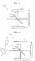
- FIG. 1 shows a schematic configuration of a Fourier transform interferometer 100 according to an embodiment.
- the Fourier transform interferometer 100 may include a transflective mirror 111 that transmits a part of an incident light and reflects a remaining part of the incident light, a phase change plate 120 that reflects the incident light and locally changes a phase of the reflected light differently, a mirror 112 that reflects the light reflected from the phase change plate 120 toward the transflective mirror 111, and a photodetector 130 that detects light.
- the photodetector 130 may be disposed toward a first surface 111 a of the transflective mirror 111, and the mirror 112 and the phase change plate 120 may be disposed toward a second surface 111 b, which is an opposite surface to the first surface 111 a of the transflective mirror 111.
- the transflective mirror 111 may be disposed where an incident light to be analyzed is incident on the first surface 111 a of the transflective mirror 111.
- the photodetector 130 and the mirror 112 may be disposed on both sides of the transflective mirror 111.
- a part of the incident light that is incident on the first surface 111 a of the transflective mirror 111 and is to be analyzed transmits through the transflective mirror 111, and a remaining part of the incident light to be analyzed is reflected by the transflective mirror 111.
- a part of the incident light transmitted through the transflective mirror 111 is reflected by the phase change plate 120.
- the phase change plate 120 locally and differently changes the phase of the reflected light. Therefore, the light reflected by the phase change plate 120 has various phases according to a cross-sectional area of a beam.
- a part of the light reflected from the phase change plate 120 is reflected by the second surface 111b of the transflective mirror 111 and is incident on the mirror 112.
- a part of the light reflected by the mirror 112 transmits through the transflective mirror 111 and is incident on the photodetector 130.
- the light reflected from the first surface 111 a of the transflective mirror 111 is also incident on the photodetector 130. Therefore, the light not incident on the phase change plate 120 and the light reflected from the phase change plate 120 are incident on the photodetector 130. As a result, an interference pattern is formed between the light not incident on the phase change plate 120 and the light reflected from the phase change plate 120 in the incident light. Therefore, the photodetector 130 may detect the interference pattern between the light not incident on the phase change plate 120 and the light reflected from the phase change plate 120 in the incident light. Then, a spectrum distribution of the incident light may be analyzed by using a Fourier analysis method using the interference patterns detected by the photodetector 130.
- the photodetector 130 and the mirror 112 are disposed on opposite sides of the transflective mirror 111, and the phase change plate 120 is disposed toward a direction in which the incident light is incident on the transflective mirror 111.
- embodiments are not necessarily limited thereto.
- FIG. 2 shows a schematic configuration of the Fourier transform interferometer 100 according to another embodiment. Compared with FIG. 1 , positions of the phase change plate 120 and the mirror 112 are exchanged in FIG. 2 . Therefore, the photodetector 130 and the phase change plate 120 are disposed on opposite sides of the transflective mirror 111, and the mirror 112 is disposed toward a direction in which the incident light is incident on the transflective mirror 111.
- a part of an incident light that is incident on the first surface 111 a of the transflective mirror 111 and is to be analyzed transmits through the transflective mirror 111 and then is incident on the mirror 112, and a remaining part of the incident light to be analyzed is reflected by the first surface 111 a of the transflective mirror 111 and is incident on the photodetector 130.
- the light transmitted through the transflective mirror 111 is reflected by the mirror 112 and is incident on the second surface 111b of the transflective mirror 111.
- a part of the light incident on the second surface 111b of the transflective mirror 111 is reflected by the second surface 111b of the transflective mirror 111 and is incident on the phase change plate 120.
- the phase change plate 120 reflects the incident light and locally and differently changes a phase of the reflected light. Then, a part of the light reflected by the phase change plate 120 transmits through the transflective mirror 111 and is incident on the photodetector 130.
- the photodetector 130 is disposed toward the first surface 111 a of the transflective mirror 111 and the mirror 112 and the phase change plate 120 are disposed toward the second surface 111b.
- embodiments are not necessarily limited thereto.
- FIG. 3 shows a schematic configuration of the Fourier transform interferometer 100 according to another embodiment. Compared with FIG. 1 , positions of the photodetector 130 and the mirror 112 are exchanged in FIG. 3 . Therefore, the mirror 112 may be disposed toward the first surface 111 a of the transflective mirror 111, and the photodetector 130 and the phase change plate 120 may be disposed toward the second surface 111b of the transflective mirror 111.
- a part of the incident light that is incident on the first surface 111 a of the transflective mirror 111 and is to be analyzed transmits through the transflective mirror 111 and is incident on the phase change plate 120, and a remaining part of the incident light to be analyzed is reflected by the first surface 111 a of the transflective mirror 111 and is incident on the mirror 112.
- a part of the light reflected by the mirror 112 transmits through the transflective mirror 111 and is incident on the photodetector 130.
- the Fourier transform interferometer 100 may have various arrangements of the transflective mirror 111 and the mirror 112 for transmitting a part of the incident light to the phase change plate 120, transmitting a remaining part of the incident light to the photodetector 130, and transmitting the light reflected from the phase change plate 120 in the incident light to the photodetector 130.
- the incident light that is incident on the first surface 111 a of the transflective mirror 111 which may be light to be analyzed, may be light directly from an external test target light source such as a laser or may be light reflected, transmitted, or scattered from an external sample or subject.
- the Fourier transform interferometer 100 may further include a light source.
- FIG. 4 shows a schematic configuration of the Fourier transform interferometer 100 according to another embodiment.
- the Fourier transform interferometer 100 may further include a light source 110 for irradiating a sample S with light.
- the sample S, the light source 110, and the transflective mirror 111 may be disposed where light reflected, transmitted or scattered from the sample S irradiated by the light source 110 is incident on the first surface 111a of the transflective mirror 111.
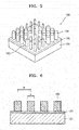
- FIG. 5 is a perspective view showing a schematic configuration of the phase change plate 120 of the Fourier transform interferometer 100 shown in FIG. 1 .
- the phase change plate 120 for locally changing a phase of reflected light may include a substrate 121, a reflective layer 122 disposed on the substrate 121, and a meta-surface 123 disposed on the reflective layer 122 and locally and differently changing the phase of the reflected light.
- the phase change plate 120 may be disposed where the reflection layer 122 and the meta surface 123 face the transflective mirror 111.
- the meta surface 123 may include a plurality of phase change elements 124 having a plurality of different diameters.
- the plurality of phase change elements 124 may have columnar shapes that protrude vertically on the reflective layer 122.
- the phase change elements 124 have cylindrical shapes in FIG. 5 but are not limited thereto.
- the phase change elements 124 may have elliptical column shapes or rectangular column shapes wherein the phase change plate 120 has a polarization-dependent characteristic.
- the substrate 121 may be formed of glass or plastic material in the form of a flat plate.
- the phase change elements 124 may be formed of a material having a higher refractive index than that of the substrate 121.
- the phase change elements 124 may be formed of a material having a high refractive index selected from the group consisting of germanium (Ge), amorphous silicon (a-Si), polycrystalline silicon (p-Si), crystalline silicon (c-Si), group III-V compound, SiNx, SiO 2 , TiO, TiO 2 , TiO 3 , GaP, Al 2 O 3 , HfO 2 , and the like.
- a refractive index of the phase change element 124 may be greater than 3.5 at, for example, a visible light wavelength.
- phase change elements 124 may be formed of a metallic material. These phase change elements 124 may be easily formed using a general semiconductor patterning process. For example, after depositing material layers of the phase change elements 124 on the reflective layer 122, the phase change elements 124 may be formed simply by patterning the phase change element material layers using a photolithography process and an etch process. Therefore, a complicated processing operation is not required to form the phase change plate 120.
- phase change elements 124 and diameters of the phase change elements 124 may be much less than a wavelength of light to be analyzed. Then, a phase may be delayed because the incident light passes through the phase change elements 124 of the high refractive index, and thus a phase of reflected light by the phase change plate 120 is different from the phase of the incident light.
- a phase change degree may vary according to parameters such as an arrangement, diameters, pitches, cross-sectional shapes, heights, and refractive indices of the phase change elements 124.
- the plurality of phase change elements 124 may be simply two-dimensionally arranged, and the phase of the reflected light may be adjusted only by the pitch and diameter of each of the phase change elements 124.
- the parameters such as the arrangement of the phase change elements 124, the cross-sectional shapes, the heights, and the like may be the same, and the phase of the reflected light may be adjusted only by the pitch and the diameter.
- FIG. 6 is a cross-sectional view showing a diameter d and a pitch P of each of the phase change elements 124 of the phase change plate 120 in the Fourier transform interferometer 100 shown in FIG. 1 .
- FIG. 7 is a graph exemplarily showing a phase change according to the diameter and the pitch of each of the phase change elements 124.
- the pitch P is an arrangement period of the phase change elements 124, and is a distance from a center of one of the phase change elements 124 to a center of another one of the phase change elements 124 adjacent thereto.
- the horizontal axis represents a ratio (d/p) between the pitch and the diameter
- the vertical axis represents a reflectance and a phase. Referring to FIG.
- the ratio (d/p) between the pitch and the diameter increases with respect to an incident light of 600 nm and 700 nm, and that the phase change gradually increases. Also, it may be seen that the reflectance is almost constant regardless of the ratio (d/p) between the pitch and the diameter. Therefore, the phase of the reflected light may be adjusted by adjusting the ratio (d/p) between the pitch and the diameter.
- the meta surface 123 may include a plurality of meta regions for differently changing the phase of the reflected light.
- FIG. 8 is a plan view showing a schematic configuration of the phase change plate 120 of the Fourier transform interferometer 100 shown in FIG. 1 .
- the meta surface 123 may include first to fourth meta regions 120a, 120b, 120c, and 120d. Although only the four meta regions 120a, 120b, 120c, and 120d are illustrated in FIG. 8 , there may actually be a greater number of meta regions.
- the first to fourth meta regions 120a, 120b, 120c, and 120d may be configured to change a phase of a reflected light differently.
- a plurality of first to fourth phase change elements 124a, 124b, 124c, and 124d that are different from each other may be respectively arranged in the first to fourth meta regions 120a, 120b, 120c, and 120d.
- the first to fourth phase change elements 124a, 124b, 124c, 124d arranged in the same meta regions 120a, 120b, 120c, and 120d all have the same diameter and pitch
- the first to fourth phase change elements 124a, 124b, 124c, and 124d arranged in the different first to fourth meta regions 120a, 120b, 120c, and 120d may be configured to have different diameters and pitches.
- phase change plate 120 may have different phases according to a local position in the phase change plate 120.
- the phase of the reflected light changes locally according to the position on the phase change plate 120.
- reflected light reflected on the first meta region 120a of the phase change plate 120 may have a first phase
- reflected light reflected on the second meta region 120b of the phase change plate 120 may have a second phase
- the second phase being different from the first phase
- reflected light reflected on the third meta region 120c of the phase change plate 120 may have a third phase
- the third phase being different from the first and second phases
- reflected light reflected on the fourth meta region 120d of the phase change plate 120 may have a fourth phase, the fourth phase being different from the first to third phases.
- the Fourier transform interferometer 100 may be manufactured in a small size.
- the Fourier transform interferometer 100 according to the present embodiment may be manufactured in a chip form and applied to a small electronic device such as a smart phone or a wearable device.
- phase change plate 120 may be simply manufactured by a patterning method using a photolithography process, a complicated processing operation is not required. Therefore, the manufacturing cost of the Fourier transform interferometer 100 may be reduced.
- the Fourier transform interferometer 100 having the configuration shown in FIGS. 1 to 4 may be implemented having a vertical-type structure or a lateral-type structure.
- FIG. 9 is a perspective view showing a vertical-type structure of the Fourier transform interferometer 100 shown in FIG. 1
- FIG. 10 is a perspective view showing a lateral-type structure of the Fourier transform interferometer 100 shown in FIG. 1 .
- the phase change plate 120 may be disposed in a bottom region of the Fourier transform interferometer 100, and the transflective mirror 111 may face an upper surface of the phase change plate 120 and be spaced apart from the phase change plate 120.
- the mirror 111 and the photodetector 130 may be respectively disposed on both sides of the transflective mirror 111.
- An incident light may be incident on the transflective mirror 111 in a vertical direction from the top to the bottom.
- FIG. 9 exemplarily shows the configuration shown in FIG. 1 .
- the configurations shown in FIG. 2 through FIG. 4 may be implemented as the vertical-type structure shown in FIG. 9 .
- the Fourier transform interferometer 100 may further include a flat substrate 101.
- all of the transflective mirror 111, the phase change plate 120, the mirror 112, and the photodetector 120 may be arranged on an upper surface of the substrate 101.
- the incident light may proceed in a horizontal direction and may be incident on the transflective mirror 111.
- FIG. 10 exemplarily shows the configuration shown in FIG. 1 .
- the configurations shown in FIG. 2 through FIG. 4 may be implemented as the vertical-type structure shown in FIG. 9 .
- the Fourier transform interferometer 100 described in FIGS. 1 to 10 is a Michelson interferometer in which the phase change plate 120 changes a phase of reflected light.
- the Fourier transform interferometer 100 may be configured as Fabry-Perot interferometer in which a phase change plate changes a phase of transmitted light.
- FIG. 11 shows a schematic configuration of a Fourier transform interferometer 200 according to another embodiment.
- the Fourier transform interferometer 200 may include a transflective mirror 210 transmitting a part of an incident light and reflecting a remaining part of the incident light, a phase change plate 220 disposed opposite to the transflective mirror 210, and a photodetector 230 disposed opposite the phase change plate 220.
- the photodetector 230 may be disposed on the opposite side of the transflective mirror 210 with respect to the phase change plate 220.
- phase change plate 220 In the configuration of the Fourier transform interferometer 200, a part of the incident light incident on the transflective mirror 210 passes through the transflective mirror 210 and is incident on the phase change plate 220. A part of light incident on the phase change plate 220 is reflected by the transflective mirror 210 and a remaining part of the light transmits through the phase change plate 220 and is incident on the photodetector 230. A part of the light reflected by the phase change plate 220 and incident on the transflective mirror 210 may be reflected again and then may transmit through the phase change plate 220 and be incident on the photodetector 230.
- the phase change plate 220 may have a meta surface that locally changes a phase of the transmitted light.
- the photodetector 230 may detect an interference pattern between the light transmitted through the phase change plate 220.
- the photodetector 230 may detect an interference pattern between light transmitting through the phase change plate 220 once and light reciprocating one or more times between the phase change plate 220 and the transflective mirror 210. Then, a spectrum distribution of the incident light may be analyzed by a Fourier analysis method using the interference patterns detected by the photodetector 230.
- An incident light incident on the transflective mirror 210 from the outside which is light to be analyzed, may be light directly from an external test target light source such as a laser or reflected, transmitted or scattered from an external sample or subject.
- an external test target light source such as a laser or reflected, transmitted or scattered from an external sample or subject.
- the Fourier transform interferometer 200 may further include a light source.
- FIG. 12 shows a schematic configuration of the Fourier transform interferometer 200 according to another embodiment.
- the Fourier transform interferometer 200 may further include the light source 110 for irradiating the sample S with light.
- the sample S, the light source 110, and the transflective mirror 210 may be arranged where light reflected, transmitted or scattered from the sample S irradiated by the light source 110 may be incident on the transflective mirror 210.
- FIG. 13 is a perspective view showing a schematic configuration of the phase change plate 220 of the Fourier transform interferometer 200 shown in FIG. 11 .
- the phase change plate 220 for locally and differently changing a phase of a transmitted light may include the substrate 121 and the meta surface 123 disposed on the substrate 121 and locally and differently changing a phase of a reflected light.
- the meta surface 123 may include a plurality of meta regions for differently changing the phase of the reflected light, and the phase change elements 124 having a plurality of different diameters may be arranged in the plurality of meta regions. Therefore, compared with the phase change plate 120 of FIG. 5 , the phase change plate 220 shown in FIG. 13 may have the same configuration as that of the phase change plate 120 shown in FIG. 5 except that the phase change plate 220 shown in FIG. 13 does not include the reflective layer 122.
- the substrate 121 of the phase change plate 220 may be formed of a material having transparency with the light to be analyzed.
- the substrate 121 may be formed of glass or a transparent plastic material.
- the substrate 121 may have transflectivity to reflect a part of the incident light to the transflective mirror 210.
- the Fourier transform interferometer 200 having the configuration shown in FIGS. 11 and 12 described above may also be implemented having a vertical-type structure or a lateral-type structure.
- FIG. 14 is a perspective view showing a vertical-type structure of the Fourier transform interferometer 200 shown in FIG. 11
- FIG. 15 is a perspective view showing a lateral-type structure of the Fourier transform interferometer 200 shown in FIG. 11 .
- the photodetector 230 may be disposed in a bottom region of the Fourier transform interferometer 200 and the phase change plate 220 may face an upper surface of the photodetector 230 and be spaced apart from the photodetector 230.
- the transflective mirror 210 may face an upper surface of the phase change plate 220 and be spaced apart from the phase change plate 220.
- An incident light may travel in a perpendicular direction from the top to the bottom and be incident on the transflective mirror 210.
- the Fourier transform interferometer 200 may further include a flat substrate 201.
- the transflective mirror 210, the phase change plate 220, and the photodetector 230 may be sequentially arranged in a lateral direction on an upper surface of the substrate 201.
- the incident light may travel in a horizontal direction and be incident on the transflective mirror 210.
Landscapes
- Physics & Mathematics (AREA)
- Spectroscopy & Molecular Physics (AREA)
- General Physics & Mathematics (AREA)
- Nonlinear Science (AREA)
- Optics & Photonics (AREA)
- Instruments For Measurement Of Length By Optical Means (AREA)
- Spectrometry And Color Measurement (AREA)
- Investigating Or Analysing Materials By Optical Means (AREA)
Claims (15)
- Ein Fourier-Transformationsinterferometer (100), umfassend:eine Phasenänderungsplatte (120), umfassend:eine reflektierende Schicht (122), die so konfiguriert ist, dass sie ein erstes Licht, das einfällt, reflektiert; undeine Meta-Oberfläche (123), die so konfiguriert ist, dass sie eine Phase des ersten Lichts, das reflektiert wird, lokal und unterschiedlich ändert;einen Photodetektor (130), der so konfiguriert ist, dass er ein zweites Licht erfasst; undeinen transflektiven Spiegel (111) und einen Spiegel (112), die konfiguriert sind, um:einen ersten Teil eines dritten Lichts, das einfällt, zu der Phasenänderungsplatte (120) zu übertragen;einen restlichen Teil des dritten Lichts zu dem Photodetektor (130) zu übertragen; unddas erste Licht, dessen Phase lokal und unterschiedlich geändert wird, zu dem Photodetektor (130) zu übertragen,wobei der Photodetektor (130) ferner so konfiguriert ist, dass er ein Interferenzmuster zwischen dem verbleibenden Teil des dritten Lichts und dem ersten Licht, dessen Phase lokal und unterschiedlich verändert ist, erfasst.
- Das Fourier-Transformationsinterferometer (100) nach Anspruch 1, wobei die Phasenänderungsplatte (120) ferner ein Substrat (121) umfasst,
die reflektierende Schicht (122) auf dem Substrat (121) angeordnet ist,
die Meta-Oberfläche (123) auf der reflektierenden Schicht (122) angeordnet ist, und
die Meta-Oberfläche (123) eine Vielzahl von Phasenänderungselementen (124) mit unterschiedlichen Durchmessern umfasst, wobei die Vielzahl von Phasenänderungselementen (124) säulenartige Formen aufweisen, die vertikal von der reflektierenden Schicht (122) hervorstehen. - Das Fourier-Transformationsinterferometer (100) nach einem der Ansprüche 1 oder 2, wobei die Phasenänderungsplatte (120) einen ersten Metabereich (120a) und einen zweiten Metabereich (120b) aufweist, die die Phase des ersten reflektierten Lichts unterschiedlich verändern.
- Das Fourier-Transformationsinterferometer (100) nach Anspruch 3, wobei die Phasenänderungsplatte (120) erste Phasenänderungselemente (124a), die in dem ersten Metabereich (120a) angeordnet sind, und zweite Phasenänderungselemente (124b), die in dem zweiten Metabereich (120b) angeordnet sind, umfasst, und wobei jedes der ersten Phasenänderungselemente (124a) einen ersten Durchmesser aufweist, und
jedes der zweiten Phasenänderungselemente (124b) einen zweiten Durchmesser aufweist, der sich von dem ersten Durchmesser unterscheidet. - Das Fourier-Transformationsinterferometer (100) nach Anspruch 2, wobei jeder der verschiedenen Durchmesser der Vielzahl von Phasenänderungselementen (124) kleiner ist als eine Wellenlänge des ersten Lichts, und
wobei jeder der Brechungsindizes der Vielzahl von Phasenänderungselementen (124) höher ist als ein Brechungsindex des Substrats (121). - Das Fourier-Transforminterferometer (100) nach einem der Ansprüche 1 bis 5, wobei der Photodetektor (130) in Richtung einer ersten Oberfläche (111a) des transflektiven Spiegels (111) angeordnet ist,
der Spiegel (112) und die Phasenänderungsplatte (120) in Richtung einer zweiten Oberfläche (111b) gegenüber der ersten Oberfläche (111a) des transflektiven Spiegels (111) angeordnet sind, und
der transflektive Spiegel (111) so angeordnet ist, dass das dritte Licht auf die erste Oberfläche (111a) des transflektiven Spiegels (111) einfällt. - Das Fourier-Transformationsinterferometer (100) nach einem der Ansprüche 1 bis 5, wobei der transflektive Spiegel (111) gegenüber einer oberen Fläche der Phasenänderungsplatte (120) angeordnet ist, und
der Spiegel (112) und der Photodetektor (130) jeweils auf beiden Seiten des transflektiven Spiegels (111) angeordnet sind. - Das Fourier-Transformationsinterferometer (100) nach Anspruch 1, ferner ein Substrat (101) umfassend,
wobei der transflektive Spiegel (111), die Phasenänderungsplatte (120), der Spiegel (112) und der Photodetektor (130) auf dem Substrat (101) angeordnet sind. - Das Fourier-Transformationsinterferometer (100) nach einem der Ansprüche 1 bis 8, ferner umfassend eine Lichtquelle (110), die so konfiguriert ist, dass sie ein viertes Licht auf eine Probe strahlt.
- Ein Fourier-Transformationsinterferometer (200), umfassend:einen transflektiven Spiegel (210), der so konfiguriert ist, dass er einen ersten Teil eines einfallenden Lichts durchlässt und einen restlichen Teil des einfallenden Lichts reflektiert;eine Phasenänderungsplatte (220), die gegenüber dem transflektiven Spiegel (210) angeordnet ist und eine Meta-Oberfläche (123) umfasst, die so konfiguriert ist, dass sie eine Phase des Lichts, das einfällt, nachdem es von dem transflektiven Spiegel (210) durchgelassen wurde, lokal und unterschiedlich ändert; undeinen Photodetektor (230), der so konfiguriert ist, dass er ein Interferenzmuster zwischen Licht, das durch die Phasenänderungsplatte (220) durchgelassen wurde und eine lokale Phasenänderung erfahren hat, und Licht, das von der Phasenänderungsplatte (220) und dem transflektiven Spiegel (210) reflektiert wird, erfasst.
- Das Fourier-Transformationsinterferometer (200) nach Anspruch 10, wobei die Phasenänderungsplatte (220) ferner ein transflektives Substrat (121) umfasst, das so konfiguriert ist, dass es einen Teil des Lichts, das auf die Phasenänderungsplatte (220) einfällt, durchlässt, um die lokale Phasenänderung zu erfahren, und einen verbleibenden Teil des Lichts, das auf die Phasenänderungsplatte (220) einfällt, reflektiert,
die Meta-Oberfläche (123) auf dem Substrat (121) angeordnet ist, und
die Meta-Oberfläche (123) eine Vielzahl von Phasenänderungselementen (124) mit unterschiedlichen Durchmessern umfasst, und
wobei die Vielzahl von Phasenänderungselementen (124) säulenartige Formen haben, die vertikal aus dem Substrat (121) herausragen. - Das Fourier-Transformationsinterferometer (200) nach einem der Ansprüche 10 bis 11, wobei die Phasenänderungsplatte (220) einen ersten Meta-Bereich und einen zweiten Meta-Bereich umfasst, die die Phase des verbleibenden Teils des Lichts, das von der Phasenänderungsplatte (220) und dem transflektiven Spiegel (210) reflektiert wird, unterschiedlich ändern.
- Das Fourier-Transformationsinterferometer (200) nach Anspruch 12, wobei die Phasenänderungsplatte (220) erste Phasenänderungselemente, die im ersten Metabereich angeordnet sind, und zweite Phasenänderungselemente, die im zweiten Metabereich angeordnet sind, umfasst, und
wobei jedes der ersten Phasenänderungselemente einen ersten Durchmesser aufweist, und
jedes der zweiten Phasenänderungselemente einen zweiten Durchmesser aufweist, der sich von dem ersten Durchmesser unterscheidet. - Das Fourier-Transforminterferometer (200) nach Anspruch 11, wobei jeder der verschiedenen Durchmesser der Vielzahl von Phasenänderungselementen (124) kleiner ist als eine Wellenlänge des zu analysierenden Lichts, und
wobei jeder der Brechungsindizes der Vielzahl von Phasenänderungselementen (124) höher ist als ein Brechungsindex des Substrats (121). - Das Fourier-Transformationsinterferometer (200) nach Anspruch 10, wobei der Photodetektor (230), die Phasenänderungsplatte (220) und der transflektive Spiegel (210) aufeinanderfolgend in einer vertikalen Richtung angeordnet sind, und das Fourier-Transformationsinterferometer (200) ferner umfassend:ein Substrat (201),wobei der transflektive Spiegel (210), die Phasenänderungsplatte (220) und der Photodetektor (230) aufeinanderfolgend in einer seitlichen Richtung auf dem Substrat (201) angeordnet sind, undeine Lichtquelle (110), die so konfiguriert ist, dass sie ein Licht in Richtung einer Probe ausstrahlt.
Applications Claiming Priority (1)
| Application Number | Priority Date | Filing Date | Title |
|---|---|---|---|
| KR1020170155810A KR102561100B1 (ko) | 2017-11-21 | 2017-11-21 | 메타 표면을 이용한 푸리에 변환 간섭계 |
Publications (2)
| Publication Number | Publication Date |
|---|---|
| EP3486602A1 EP3486602A1 (de) | 2019-05-22 |
| EP3486602B1 true EP3486602B1 (de) | 2021-05-19 |
Family
ID=64331915
Family Applications (1)
| Application Number | Title | Priority Date | Filing Date |
|---|---|---|---|
| EP18206731.4A Active EP3486602B1 (de) | 2017-11-21 | 2018-11-16 | Fourier-transformationsinterferometer mit meta-oberfläche |
Country Status (4)
| Country | Link |
|---|---|
| US (2) | US10627695B2 (de) |
| EP (1) | EP3486602B1 (de) |
| KR (1) | KR102561100B1 (de) |
| CN (1) | CN109813430B (de) |
Families Citing this family (7)
| Publication number | Priority date | Publication date | Assignee | Title |
|---|---|---|---|---|
| JP6512388B1 (ja) | 2017-10-19 | 2019-05-15 | 日本精工株式会社 | 伸縮リンク及びサスペンション |
| KR102877637B1 (ko) | 2019-03-29 | 2025-10-27 | 삼성전자주식회사 | 다파장 광을 이용한 광학 장치 및 그 동작 방법 |
| US12025438B2 (en) * | 2020-08-24 | 2024-07-02 | The Curators Of The University Of Missouri | Miniature 3D position-to-optical displacement sensor |
| EP4404476A4 (de) | 2021-11-02 | 2025-03-12 | Samsung Electronics Co., Ltd. | Kommunikationssystem und verfahren mit grosser intelligenter oberfläche |
| CN115112238A (zh) * | 2022-07-07 | 2022-09-27 | 天津山河光电科技有限公司 | 一种超表面空间光谱仪 |
| CN115164714B (zh) * | 2022-08-18 | 2025-01-07 | 深圳迈塔兰斯科技有限公司 | 一种干涉系统 |
| WO2024088727A1 (en) * | 2022-10-28 | 2024-05-02 | Asml Netherlands B.V. | Compact optical arrangement for a metrology system |
Citations (1)
| Publication number | Priority date | Publication date | Assignee | Title |
|---|---|---|---|---|
| US20060232781A1 (en) * | 2004-11-18 | 2006-10-19 | Morgan Research Corporation | Miniature fourier transform spectrophotometer |
Family Cites Families (14)
| Publication number | Priority date | Publication date | Assignee | Title |
|---|---|---|---|---|
| DE4431412C1 (de) | 1994-08-24 | 1996-03-14 | William Newton | Vorrichtung zur Durchführung spektroskopischer Messungen |
| US5600440A (en) | 1995-07-05 | 1997-02-04 | The United States Of America As Represented By The Secretary Of The Navy | Liquid crystal interferometer |
| US7844145B1 (en) | 2008-04-14 | 2010-11-30 | The United States Of America As Represented By The Secretary Of The Navy | MEMS-based multi-channel Fabry-Perot interferometer system with increased tuning range and resolution |
| CN101819063B (zh) * | 2009-12-29 | 2011-10-05 | 南京邮电大学 | 相位调制凹槽阵列微型光谱仪 |
| CN101858786B (zh) * | 2009-12-29 | 2012-09-26 | 南京邮电大学 | 相位调制台阶阵列微型光谱仪 |
| GB201000775D0 (en) | 2010-01-18 | 2010-03-03 | Stfc Science & Technology | Interferometer spectrometer |
| US8655189B2 (en) | 2010-06-18 | 2014-02-18 | Exelis, Inc. | Optical modulation utilizing structures including metamaterials |
| WO2013116516A1 (en) | 2012-02-03 | 2013-08-08 | Wayne State University | Fourier-transform interferometer with staircase reflective element |
| US20170082842A1 (en) | 2014-01-30 | 2017-03-23 | Shaltout Amr Mohammad E A | Ultra-small cavity with reflecting metasurfaces |
| CA2938319C (en) | 2014-05-27 | 2017-07-11 | GHGSat Inc. | Fabry-perot interferometer based satellite detection of atmospheric trace gases |
| US9946051B2 (en) | 2015-04-22 | 2018-04-17 | Samsung Electronics Co., Ltd. | Imaging apparatus and image sensor including the same |
| US10168214B2 (en) * | 2015-05-15 | 2019-01-01 | Trutag Technologies, Inc. | Method of assembly and manufacturing of piezo actuated Fabry-Perot interferometer |
| US10514296B2 (en) * | 2015-07-29 | 2019-12-24 | Samsung Electronics Co., Ltd. | Spectrometer including metasurface |
| CN108120505A (zh) * | 2017-12-20 | 2018-06-05 | 中国科学院长春光学精密机械与物理研究所 | 基于阶梯相位反射镜与光开关阵列的红外干涉光谱仪 |
-
2017
- 2017-11-21 KR KR1020170155810A patent/KR102561100B1/ko active Active
-
2018
- 2018-10-11 CN CN201811186556.9A patent/CN109813430B/zh active Active
- 2018-11-13 US US16/188,825 patent/US10627695B2/en active Active
- 2018-11-16 EP EP18206731.4A patent/EP3486602B1/de active Active
-
2019
- 2019-12-11 US US16/710,025 patent/US10877349B2/en active Active
Patent Citations (1)
| Publication number | Priority date | Publication date | Assignee | Title |
|---|---|---|---|---|
| US20060232781A1 (en) * | 2004-11-18 | 2006-10-19 | Morgan Research Corporation | Miniature fourier transform spectrophotometer |
Also Published As
| Publication number | Publication date |
|---|---|
| US20190155124A1 (en) | 2019-05-23 |
| KR102561100B1 (ko) | 2023-07-28 |
| CN109813430A (zh) | 2019-05-28 |
| CN109813430B (zh) | 2023-04-11 |
| KR20190058131A (ko) | 2019-05-29 |
| US20200110323A1 (en) | 2020-04-09 |
| US10877349B2 (en) | 2020-12-29 |
| EP3486602A1 (de) | 2019-05-22 |
| US10627695B2 (en) | 2020-04-21 |
Similar Documents
| Publication | Publication Date | Title |
|---|---|---|
| US10877349B2 (en) | Fourier-transform interferometer using meta surface | |
| KR102436236B1 (ko) | 광변조 마이크로 나노 구조, 마이크로 통합 스펙트로미터 및 스펙트럼 변조 방법 | |
| US10539719B2 (en) | Photonic apparatus with periodic structures | |
| EP2682741B1 (de) | Vorrichtung zur messung optischer eigenschaften und verfahren zur messung optischer eigenschaften | |
| US9176279B2 (en) | Analyzing light by mode interference | |
| KR102395781B1 (ko) | 서브 파장 이중 격자를 포함하는 광학 필터 및 분광기 | |
| US6829073B1 (en) | Optical reading system and method for spectral multiplexing of resonant waveguide gratings | |
| US5555472A (en) | Method and apparatus for measuring film thickness in multilayer thin film stack by comparison to a reference library of theoretical signatures | |
| US20190101373A1 (en) | Apparatus for measuring thickness and surface profile of multilayered film structure using imaging spectral optical system and measuring method | |
| TW200530571A (en) | Photonic crystal sensors | |
| JP2013513112A (ja) | ファブリーペローフーリエ変換分光計 | |
| US20160202038A1 (en) | Thickness measuring apparatus and thickness measuring method | |
| US20190003820A1 (en) | Common-path integrated low coherence interferometry system and method therefor | |
| EP3182078A1 (de) | Stehwellenintegrierte fts mit breitbandbetrieb | |
| US11747277B2 (en) | Optical component for an interferometric imaging device | |
| US20050122529A1 (en) | Measurement system of three-dimensional shape of transparent thin film using acousto-optic tunable filter | |
| KR102715035B1 (ko) | 서브 파장 리플렉터를 포함하는 광학 필터, 분광기 및 이를 포함하는 전자 장치 | |
| KR100699317B1 (ko) | 두께 및 형상 측정 시스템 | |
| Tong et al. | A Single Waveguide Spectrometer via Defect Scattering | |
| KR101486272B1 (ko) | 투명 기판 모니터링 장치 및 투명 기판 측정 방법 | |
| Zhao et al. | High transmittance mid-wave infrared MEMS-FP filter with compensating layer structure | |
| TWI502176B (zh) | 可調式濾光元件及其製作方法 | |
| TW201825862A (zh) | 用來判斷在樣本堆疊中之層厚度的方法及組件 | |
| KR100747044B1 (ko) | 두께 및 형상 측정 시스템 |
Legal Events
| Date | Code | Title | Description |
|---|---|---|---|
| PUAI | Public reference made under article 153(3) epc to a published international application that has entered the european phase |
Free format text: ORIGINAL CODE: 0009012 |
|
| STAA | Information on the status of an ep patent application or granted ep patent |
Free format text: STATUS: THE APPLICATION HAS BEEN PUBLISHED |
|
| AK | Designated contracting states |
Kind code of ref document: A1 Designated state(s): AL AT BE BG CH CY CZ DE DK EE ES FI FR GB GR HR HU IE IS IT LI LT LU LV MC MK MT NL NO PL PT RO RS SE SI SK SM TR |
|
| AX | Request for extension of the european patent |
Extension state: BA ME |
|
| STAA | Information on the status of an ep patent application or granted ep patent |
Free format text: STATUS: REQUEST FOR EXAMINATION WAS MADE |
|
| 17P | Request for examination filed |
Effective date: 20191121 |
|
| RBV | Designated contracting states (corrected) |
Designated state(s): AL AT BE BG CH CY CZ DE DK EE ES FI FR GB GR HR HU IE IS IT LI LT LU LV MC MK MT NL NO PL PT RO RS SE SI SK SM TR |
|
| STAA | Information on the status of an ep patent application or granted ep patent |
Free format text: STATUS: EXAMINATION IS IN PROGRESS |
|
| 17Q | First examination report despatched |
Effective date: 20200402 |
|
| GRAP | Despatch of communication of intention to grant a patent |
Free format text: ORIGINAL CODE: EPIDOSNIGR1 |
|
| STAA | Information on the status of an ep patent application or granted ep patent |
Free format text: STATUS: GRANT OF PATENT IS INTENDED |
|
| INTG | Intention to grant announced |
Effective date: 20201204 |
|
| GRAS | Grant fee paid |
Free format text: ORIGINAL CODE: EPIDOSNIGR3 |
|
| GRAA | (expected) grant |
Free format text: ORIGINAL CODE: 0009210 |
|
| STAA | Information on the status of an ep patent application or granted ep patent |
Free format text: STATUS: THE PATENT HAS BEEN GRANTED |
|
| AK | Designated contracting states |
Kind code of ref document: B1 Designated state(s): AL AT BE BG CH CY CZ DE DK EE ES FI FR GB GR HR HU IE IS IT LI LT LU LV MC MK MT NL NO PL PT RO RS SE SI SK SM TR |
|
| REG | Reference to a national code |
Ref country code: GB Ref legal event code: FG4D |
|
| REG | Reference to a national code |
Ref country code: CH Ref legal event code: EP |
|
| REG | Reference to a national code |
Ref country code: DE Ref legal event code: R096 Ref document number: 602018017227 Country of ref document: DE |
|
| REG | Reference to a national code |
Ref country code: AT Ref legal event code: REF Ref document number: 1394402 Country of ref document: AT Kind code of ref document: T Effective date: 20210615 |
|
| REG | Reference to a national code |
Ref country code: IE Ref legal event code: FG4D |
|
| REG | Reference to a national code |
Ref country code: LT Ref legal event code: MG9D |
|
| REG | Reference to a national code |
Ref country code: AT Ref legal event code: MK05 Ref document number: 1394402 Country of ref document: AT Kind code of ref document: T Effective date: 20210519 |
|
| REG | Reference to a national code |
Ref country code: NL Ref legal event code: MP Effective date: 20210519 |
|
| PG25 | Lapsed in a contracting state [announced via postgrant information from national office to epo] |
Ref country code: AT Free format text: LAPSE BECAUSE OF FAILURE TO SUBMIT A TRANSLATION OF THE DESCRIPTION OR TO PAY THE FEE WITHIN THE PRESCRIBED TIME-LIMIT Effective date: 20210519 Ref country code: BG Free format text: LAPSE BECAUSE OF FAILURE TO SUBMIT A TRANSLATION OF THE DESCRIPTION OR TO PAY THE FEE WITHIN THE PRESCRIBED TIME-LIMIT Effective date: 20210819 Ref country code: FI Free format text: LAPSE BECAUSE OF FAILURE TO SUBMIT A TRANSLATION OF THE DESCRIPTION OR TO PAY THE FEE WITHIN THE PRESCRIBED TIME-LIMIT Effective date: 20210519 Ref country code: LT Free format text: LAPSE BECAUSE OF FAILURE TO SUBMIT A TRANSLATION OF THE DESCRIPTION OR TO PAY THE FEE WITHIN THE PRESCRIBED TIME-LIMIT Effective date: 20210519 Ref country code: HR Free format text: LAPSE BECAUSE OF FAILURE TO SUBMIT A TRANSLATION OF THE DESCRIPTION OR TO PAY THE FEE WITHIN THE PRESCRIBED TIME-LIMIT Effective date: 20210519 |
|
| PG25 | Lapsed in a contracting state [announced via postgrant information from national office to epo] |
Ref country code: GR Free format text: LAPSE BECAUSE OF FAILURE TO SUBMIT A TRANSLATION OF THE DESCRIPTION OR TO PAY THE FEE WITHIN THE PRESCRIBED TIME-LIMIT Effective date: 20210820 Ref country code: IS Free format text: LAPSE BECAUSE OF FAILURE TO SUBMIT A TRANSLATION OF THE DESCRIPTION OR TO PAY THE FEE WITHIN THE PRESCRIBED TIME-LIMIT Effective date: 20210919 Ref country code: PT Free format text: LAPSE BECAUSE OF FAILURE TO SUBMIT A TRANSLATION OF THE DESCRIPTION OR TO PAY THE FEE WITHIN THE PRESCRIBED TIME-LIMIT Effective date: 20210920 Ref country code: NO Free format text: LAPSE BECAUSE OF FAILURE TO SUBMIT A TRANSLATION OF THE DESCRIPTION OR TO PAY THE FEE WITHIN THE PRESCRIBED TIME-LIMIT Effective date: 20210819 Ref country code: PL Free format text: LAPSE BECAUSE OF FAILURE TO SUBMIT A TRANSLATION OF THE DESCRIPTION OR TO PAY THE FEE WITHIN THE PRESCRIBED TIME-LIMIT Effective date: 20210519 Ref country code: LV Free format text: LAPSE BECAUSE OF FAILURE TO SUBMIT A TRANSLATION OF THE DESCRIPTION OR TO PAY THE FEE WITHIN THE PRESCRIBED TIME-LIMIT Effective date: 20210519 Ref country code: RS Free format text: LAPSE BECAUSE OF FAILURE TO SUBMIT A TRANSLATION OF THE DESCRIPTION OR TO PAY THE FEE WITHIN THE PRESCRIBED TIME-LIMIT Effective date: 20210519 Ref country code: SE Free format text: LAPSE BECAUSE OF FAILURE TO SUBMIT A TRANSLATION OF THE DESCRIPTION OR TO PAY THE FEE WITHIN THE PRESCRIBED TIME-LIMIT Effective date: 20210519 |
|
| PG25 | Lapsed in a contracting state [announced via postgrant information from national office to epo] |
Ref country code: NL Free format text: LAPSE BECAUSE OF FAILURE TO SUBMIT A TRANSLATION OF THE DESCRIPTION OR TO PAY THE FEE WITHIN THE PRESCRIBED TIME-LIMIT Effective date: 20210519 |
|
| PG25 | Lapsed in a contracting state [announced via postgrant information from national office to epo] |
Ref country code: ES Free format text: LAPSE BECAUSE OF FAILURE TO SUBMIT A TRANSLATION OF THE DESCRIPTION OR TO PAY THE FEE WITHIN THE PRESCRIBED TIME-LIMIT Effective date: 20210519 Ref country code: EE Free format text: LAPSE BECAUSE OF FAILURE TO SUBMIT A TRANSLATION OF THE DESCRIPTION OR TO PAY THE FEE WITHIN THE PRESCRIBED TIME-LIMIT Effective date: 20210519 Ref country code: SM Free format text: LAPSE BECAUSE OF FAILURE TO SUBMIT A TRANSLATION OF THE DESCRIPTION OR TO PAY THE FEE WITHIN THE PRESCRIBED TIME-LIMIT Effective date: 20210519 Ref country code: SK Free format text: LAPSE BECAUSE OF FAILURE TO SUBMIT A TRANSLATION OF THE DESCRIPTION OR TO PAY THE FEE WITHIN THE PRESCRIBED TIME-LIMIT Effective date: 20210519 Ref country code: CZ Free format text: LAPSE BECAUSE OF FAILURE TO SUBMIT A TRANSLATION OF THE DESCRIPTION OR TO PAY THE FEE WITHIN THE PRESCRIBED TIME-LIMIT Effective date: 20210519 Ref country code: DK Free format text: LAPSE BECAUSE OF FAILURE TO SUBMIT A TRANSLATION OF THE DESCRIPTION OR TO PAY THE FEE WITHIN THE PRESCRIBED TIME-LIMIT Effective date: 20210519 Ref country code: RO Free format text: LAPSE BECAUSE OF FAILURE TO SUBMIT A TRANSLATION OF THE DESCRIPTION OR TO PAY THE FEE WITHIN THE PRESCRIBED TIME-LIMIT Effective date: 20210519 |
|
| REG | Reference to a national code |
Ref country code: DE Ref legal event code: R097 Ref document number: 602018017227 Country of ref document: DE |
|
| PLBE | No opposition filed within time limit |
Free format text: ORIGINAL CODE: 0009261 |
|
| STAA | Information on the status of an ep patent application or granted ep patent |
Free format text: STATUS: NO OPPOSITION FILED WITHIN TIME LIMIT |
|
| 26N | No opposition filed |
Effective date: 20220222 |
|
| PG25 | Lapsed in a contracting state [announced via postgrant information from national office to epo] |
Ref country code: IS Free format text: LAPSE BECAUSE OF FAILURE TO SUBMIT A TRANSLATION OF THE DESCRIPTION OR TO PAY THE FEE WITHIN THE PRESCRIBED TIME-LIMIT Effective date: 20210919 Ref country code: AL Free format text: LAPSE BECAUSE OF FAILURE TO SUBMIT A TRANSLATION OF THE DESCRIPTION OR TO PAY THE FEE WITHIN THE PRESCRIBED TIME-LIMIT Effective date: 20210519 |
|
| PG25 | Lapsed in a contracting state [announced via postgrant information from national office to epo] |
Ref country code: MC Free format text: LAPSE BECAUSE OF FAILURE TO SUBMIT A TRANSLATION OF THE DESCRIPTION OR TO PAY THE FEE WITHIN THE PRESCRIBED TIME-LIMIT Effective date: 20210519 |
|
| REG | Reference to a national code |
Ref country code: CH Ref legal event code: PL |
|
| PG25 | Lapsed in a contracting state [announced via postgrant information from national office to epo] |
Ref country code: LU Free format text: LAPSE BECAUSE OF NON-PAYMENT OF DUE FEES Effective date: 20211116 Ref country code: IT Free format text: LAPSE BECAUSE OF FAILURE TO SUBMIT A TRANSLATION OF THE DESCRIPTION OR TO PAY THE FEE WITHIN THE PRESCRIBED TIME-LIMIT Effective date: 20210519 Ref country code: BE Free format text: LAPSE BECAUSE OF NON-PAYMENT OF DUE FEES Effective date: 20211130 |
|
| REG | Reference to a national code |
Ref country code: BE Ref legal event code: MM Effective date: 20211130 |
|
| PG25 | Lapsed in a contracting state [announced via postgrant information from national office to epo] |
Ref country code: LI Free format text: LAPSE BECAUSE OF NON-PAYMENT OF DUE FEES Effective date: 20211130 Ref country code: CH Free format text: LAPSE BECAUSE OF NON-PAYMENT OF DUE FEES Effective date: 20211130 |
|
| PG25 | Lapsed in a contracting state [announced via postgrant information from national office to epo] |
Ref country code: IE Free format text: LAPSE BECAUSE OF NON-PAYMENT OF DUE FEES Effective date: 20211116 |
|
| PG25 | Lapsed in a contracting state [announced via postgrant information from national office to epo] |
Ref country code: FR Free format text: LAPSE BECAUSE OF NON-PAYMENT OF DUE FEES Effective date: 20211130 |
|
| P01 | Opt-out of the competence of the unified patent court (upc) registered |
Effective date: 20230520 |
|
| PG25 | Lapsed in a contracting state [announced via postgrant information from national office to epo] |
Ref country code: CY Free format text: LAPSE BECAUSE OF FAILURE TO SUBMIT A TRANSLATION OF THE DESCRIPTION OR TO PAY THE FEE WITHIN THE PRESCRIBED TIME-LIMIT Effective date: 20210519 |
|
| GBPC | Gb: european patent ceased through non-payment of renewal fee |
Effective date: 20221116 |
|
| PG25 | Lapsed in a contracting state [announced via postgrant information from national office to epo] |
Ref country code: HU Free format text: LAPSE BECAUSE OF FAILURE TO SUBMIT A TRANSLATION OF THE DESCRIPTION OR TO PAY THE FEE WITHIN THE PRESCRIBED TIME-LIMIT; INVALID AB INITIO Effective date: 20181116 |
|
| PG25 | Lapsed in a contracting state [announced via postgrant information from national office to epo] |
Ref country code: GB Free format text: LAPSE BECAUSE OF NON-PAYMENT OF DUE FEES Effective date: 20221116 |
|
| PG25 | Lapsed in a contracting state [announced via postgrant information from national office to epo] |
Ref country code: MK Free format text: LAPSE BECAUSE OF FAILURE TO SUBMIT A TRANSLATION OF THE DESCRIPTION OR TO PAY THE FEE WITHIN THE PRESCRIBED TIME-LIMIT Effective date: 20210519 |
|
| PG25 | Lapsed in a contracting state [announced via postgrant information from national office to epo] |
Ref country code: MT Free format text: LAPSE BECAUSE OF FAILURE TO SUBMIT A TRANSLATION OF THE DESCRIPTION OR TO PAY THE FEE WITHIN THE PRESCRIBED TIME-LIMIT Effective date: 20210519 |
|
| PG25 | Lapsed in a contracting state [announced via postgrant information from national office to epo] |
Ref country code: TR Free format text: LAPSE BECAUSE OF FAILURE TO SUBMIT A TRANSLATION OF THE DESCRIPTION OR TO PAY THE FEE WITHIN THE PRESCRIBED TIME-LIMIT Effective date: 20210519 |
|
| PGFP | Annual fee paid to national office [announced via postgrant information from national office to epo] |
Ref country code: DE Payment date: 20251022 Year of fee payment: 8 |