EP3486578A1 - Refrigeration device - Google Patents
Refrigeration device Download PDFInfo
- Publication number
- EP3486578A1 EP3486578A1 EP17836720.7A EP17836720A EP3486578A1 EP 3486578 A1 EP3486578 A1 EP 3486578A1 EP 17836720 A EP17836720 A EP 17836720A EP 3486578 A1 EP3486578 A1 EP 3486578A1
- Authority
- EP
- European Patent Office
- Prior art keywords
- utilization
- liquid
- refrigerant
- heat source
- expansion valve
- Prior art date
- Legal status (The legal status is an assumption and is not a legal conclusion. Google has not performed a legal analysis and makes no representation as to the accuracy of the status listed.)
- Granted
Links
Images

Classifications
-
- F—MECHANICAL ENGINEERING; LIGHTING; HEATING; WEAPONS; BLASTING
- F25—REFRIGERATION OR COOLING; COMBINED HEATING AND REFRIGERATION SYSTEMS; HEAT PUMP SYSTEMS; MANUFACTURE OR STORAGE OF ICE; LIQUEFACTION SOLIDIFICATION OF GASES
- F25B—REFRIGERATION MACHINES, PLANTS OR SYSTEMS; COMBINED HEATING AND REFRIGERATION SYSTEMS; HEAT PUMP SYSTEMS
- F25B1/00—Compression machines, plants or systems with non-reversible cycle
-
- F—MECHANICAL ENGINEERING; LIGHTING; HEATING; WEAPONS; BLASTING
- F25—REFRIGERATION OR COOLING; COMBINED HEATING AND REFRIGERATION SYSTEMS; HEAT PUMP SYSTEMS; MANUFACTURE OR STORAGE OF ICE; LIQUEFACTION SOLIDIFICATION OF GASES
- F25B—REFRIGERATION MACHINES, PLANTS OR SYSTEMS; COMBINED HEATING AND REFRIGERATION SYSTEMS; HEAT PUMP SYSTEMS
- F25B47/00—Arrangements for preventing or removing deposits or corrosion, not provided for in another subclass
- F25B47/02—Defrosting cycles
- F25B47/022—Defrosting cycles hot gas defrosting
- F25B47/025—Defrosting cycles hot gas defrosting by reversing the cycle
-
- F—MECHANICAL ENGINEERING; LIGHTING; HEATING; WEAPONS; BLASTING
- F25—REFRIGERATION OR COOLING; COMBINED HEATING AND REFRIGERATION SYSTEMS; HEAT PUMP SYSTEMS; MANUFACTURE OR STORAGE OF ICE; LIQUEFACTION SOLIDIFICATION OF GASES
- F25B—REFRIGERATION MACHINES, PLANTS OR SYSTEMS; COMBINED HEATING AND REFRIGERATION SYSTEMS; HEAT PUMP SYSTEMS
- F25B41/00—Fluid-circulation arrangements
- F25B41/20—Disposition of valves, e.g. of on-off valves or flow control valves
-
- F—MECHANICAL ENGINEERING; LIGHTING; HEATING; WEAPONS; BLASTING
- F25—REFRIGERATION OR COOLING; COMBINED HEATING AND REFRIGERATION SYSTEMS; HEAT PUMP SYSTEMS; MANUFACTURE OR STORAGE OF ICE; LIQUEFACTION SOLIDIFICATION OF GASES
- F25B—REFRIGERATION MACHINES, PLANTS OR SYSTEMS; COMBINED HEATING AND REFRIGERATION SYSTEMS; HEAT PUMP SYSTEMS
- F25B41/00—Fluid-circulation arrangements
- F25B41/20—Disposition of valves, e.g. of on-off valves or flow control valves
- F25B41/24—Arrangement of shut-off valves for disconnecting a part of the refrigerant cycle, e.g. an outdoor part
-
- F—MECHANICAL ENGINEERING; LIGHTING; HEATING; WEAPONS; BLASTING
- F25—REFRIGERATION OR COOLING; COMBINED HEATING AND REFRIGERATION SYSTEMS; HEAT PUMP SYSTEMS; MANUFACTURE OR STORAGE OF ICE; LIQUEFACTION SOLIDIFICATION OF GASES
- F25B—REFRIGERATION MACHINES, PLANTS OR SYSTEMS; COMBINED HEATING AND REFRIGERATION SYSTEMS; HEAT PUMP SYSTEMS
- F25B41/00—Fluid-circulation arrangements
- F25B41/30—Expansion means; Dispositions thereof
- F25B41/39—Dispositions with two or more expansion means arranged in series, i.e. multi-stage expansion, on a refrigerant line leading to the same evaporator
-
- F—MECHANICAL ENGINEERING; LIGHTING; HEATING; WEAPONS; BLASTING
- F25—REFRIGERATION OR COOLING; COMBINED HEATING AND REFRIGERATION SYSTEMS; HEAT PUMP SYSTEMS; MANUFACTURE OR STORAGE OF ICE; LIQUEFACTION SOLIDIFICATION OF GASES
- F25B—REFRIGERATION MACHINES, PLANTS OR SYSTEMS; COMBINED HEATING AND REFRIGERATION SYSTEMS; HEAT PUMP SYSTEMS
- F25B2313/00—Compression machines, plants or systems with reversible cycle not otherwise provided for
- F25B2313/006—Compression machines, plants or systems with reversible cycle not otherwise provided for two pipes connecting the outdoor side to the indoor side with multiple indoor units
-
- F—MECHANICAL ENGINEERING; LIGHTING; HEATING; WEAPONS; BLASTING
- F25—REFRIGERATION OR COOLING; COMBINED HEATING AND REFRIGERATION SYSTEMS; HEAT PUMP SYSTEMS; MANUFACTURE OR STORAGE OF ICE; LIQUEFACTION SOLIDIFICATION OF GASES
- F25B—REFRIGERATION MACHINES, PLANTS OR SYSTEMS; COMBINED HEATING AND REFRIGERATION SYSTEMS; HEAT PUMP SYSTEMS
- F25B2400/00—Component parts or details not otherwise provided for in this subclass
- F25B2400/13—Economisers
-
- F—MECHANICAL ENGINEERING; LIGHTING; HEATING; WEAPONS; BLASTING
- F25—REFRIGERATION OR COOLING; COMBINED HEATING AND REFRIGERATION SYSTEMS; HEAT PUMP SYSTEMS; MANUFACTURE OR STORAGE OF ICE; LIQUEFACTION SOLIDIFICATION OF GASES
- F25B—REFRIGERATION MACHINES, PLANTS OR SYSTEMS; COMBINED HEATING AND REFRIGERATION SYSTEMS; HEAT PUMP SYSTEMS
- F25B2600/00—Control issues
- F25B2600/25—Control of valves
- F25B2600/2513—Expansion valves
-
- F—MECHANICAL ENGINEERING; LIGHTING; HEATING; WEAPONS; BLASTING
- F25—REFRIGERATION OR COOLING; COMBINED HEATING AND REFRIGERATION SYSTEMS; HEAT PUMP SYSTEMS; MANUFACTURE OR STORAGE OF ICE; LIQUEFACTION SOLIDIFICATION OF GASES
- F25B—REFRIGERATION MACHINES, PLANTS OR SYSTEMS; COMBINED HEATING AND REFRIGERATION SYSTEMS; HEAT PUMP SYSTEMS
- F25B2600/00—Control issues
- F25B2600/25—Control of valves
- F25B2600/2521—On-off valves controlled by pulse signals
-
- F—MECHANICAL ENGINEERING; LIGHTING; HEATING; WEAPONS; BLASTING
- F25—REFRIGERATION OR COOLING; COMBINED HEATING AND REFRIGERATION SYSTEMS; HEAT PUMP SYSTEMS; MANUFACTURE OR STORAGE OF ICE; LIQUEFACTION SOLIDIFICATION OF GASES
- F25B—REFRIGERATION MACHINES, PLANTS OR SYSTEMS; COMBINED HEATING AND REFRIGERATION SYSTEMS; HEAT PUMP SYSTEMS
- F25B2700/00—Sensing or detecting of parameters; Sensors therefor
- F25B2700/19—Pressures
- F25B2700/191—Pressures near an expansion valve
-
- F—MECHANICAL ENGINEERING; LIGHTING; HEATING; WEAPONS; BLASTING
- F25—REFRIGERATION OR COOLING; COMBINED HEATING AND REFRIGERATION SYSTEMS; HEAT PUMP SYSTEMS; MANUFACTURE OR STORAGE OF ICE; LIQUEFACTION SOLIDIFICATION OF GASES
- F25B—REFRIGERATION MACHINES, PLANTS OR SYSTEMS; COMBINED HEATING AND REFRIGERATION SYSTEMS; HEAT PUMP SYSTEMS
- F25B2700/00—Sensing or detecting of parameters; Sensors therefor
- F25B2700/21—Temperatures
- F25B2700/2103—Temperatures near a heat exchanger
Definitions
- the present invention relates to a refrigeration apparatus that circulates a refrigerant through a refrigerant circuit to perform a refrigeration cycle.
- a refrigerant circuit of a refrigeration apparatus that performs a refrigeration cycle may be provided with a solenoid valve to control the flow of a refrigerant.
- a general solenoid valve interrupts the passage of electric current through a solenoid for switching between an open state and a closed state.
- the refrigerant circuit of the refrigeration apparatus includes a pipe through which a high-pressure liquid refrigerant flows.
- the pipe may be provided with a solenoid valve. When closed, the solenoid valve blocks the flow of the high-pressure liquid refrigerant. If the solenoid valve opens when there is a large differential pressure between both sides of the solenoid valve, a substantially incompressible liquid refrigerant having a relatively high density suddenly flows downstream of the solenoid valve, resulting in a liquid hammer phenomenon. This may break a pipe, an expansion valve, or any other component.
- Patent Document 1 discloses that, in order to prevent a liquid hammer phenomenon that occurs when the solenoid valve opens, a pipe through which a liquid refrigerant flows is heated with an electric heater. Specifically, heating the pipe with the electric heater allows part of the refrigerant in the pipe to evaporate, thereby producing a compressible gas refrigerant in the pipe. This reduces the degree of the sudden increase in the internal pressure of the pipe upon opening the solenoid valve.
- Patent Document 1 Japanese Unexamined Patent Publication No. H11-325654
- the refrigeration apparatus of Patent Document 1 described above needs to include the electric heater for heating the pipe in order to prevent the liquid hammer phenomenon caused upon opening the solenoid valve. This increases the number of parts of the refrigeration apparatus, resulting in an increase in the manufacturing cost. While the solenoid valve is closed, the electric heater needs to keep heating the pipe. This may increase power consumption of the refrigeration apparatus, resulting in the increase in the running cost of the refrigeration apparatus.
- a first aspect of the present disclosure is directed to a refrigeration apparatus which includes a refrigerant circuit (20) in which a heat source-side unit (11) and a utilization-side unit (12) are connected together through a liquid-side connection pipe (14) and a gas-side connection pipe (15), the refrigeration apparatus allowing a refrigerant to circulate through the refrigerant circuit (20) to perform a refrigeration cycle.
- the heat source-side unit (11) includes a compressor (31a-31c), a heat source-side heat exchanger (33), and a heat source-side expansion valve (38) provided for a pipe (53c) sending the refrigerant condensed in the heat source-side heat exchanger (33) to the liquid-side connection pipe (14),
- the utilization-side unit (12) includes a utilization-side heat exchanger (61), a utilization-side expansion valve (63), and a utilization-side solenoid valve (62), which are arranged in series.
- the utilization-side unit (12) is switchable between a cooling state where the utilization-side solenoid valve (62) opens to allow the utilization-side heat exchanger (61) to function as an evaporator, and a suspended state where the utilization-side solenoid valve (62) is closed to block the refrigerant from flowing through the utilization-side heat exchanger (61).
- the refrigeration apparatus further includes a controller (90) configured to close the heat source-side expansion valve (38) when the utilization-side unit (12) is switched from the cooling state to the suspended state, and then stop the compressor (31a-31c) and close the utilization-side solenoid valve (62).
- the heat source-side unit (11) and a plurality of utilization-side units (12) are provided for the refrigerant circuit (20).
- the refrigerant condensed in the heat source-side heat exchanger (33) of the heat source-side unit (11) flows into the utilization-side units (12) through the liquid-side connection pipe (14).
- the refrigerant supplied through the liquid-side connection pipe (14) to the utilization-side units (12) expands when passing through the associated utilization-side expansion valve (63), and then flows into the associated utilization-side heat exchanger (61) to evaporate.
- the refrigerant cools a target to be cooled, such as air.
- the controller (90) when the utilization-side unit (12) is switched from a cooling state to a suspended state, the controller (90) performs a predetermined operation. The operation of this controller (90) will be described below.
- the controller (90) first closes the heat source-side expansion valve (38). At this time, since the compressor (31a-31c) is operating, the pressure of the refrigerant in the liquid-side connection pipe (14) gradually decreases. The controller (90) then stops the compressor (31a-31c) and closes the utilization-side solenoid valve (62).
- the utilization-side solenoid valve (62) when the utilization-side solenoid valve (62) is closed, the density of the refrigerant present toward the inlet side of the utilization-side solenoid valve (62) is lowered as compared with the case where the utilization-side unit (12) is in the cooling state.
- the controller (90) when the utilization-side unit (12) is switched from the cooling state to the suspended state, the controller (90) is configured to perform a preparatory operation before closing the heat source-side expansion valve (38), the preparatory operation reducing a degree of opening of the heat source-side expansion valve (38) so that a refrigerant flowing through the liquid-side connection pipe (14) is brought into a gas-liquid two-phase state.
- the controller (90) of the second aspect closes the heat source-side expansion valve (38) after performing the preparatory operation.
- the controller (90) reduces the degree of opening of the heat source-side expansion valve (38) so that the refrigerant flowing through the liquid-side connection pipe (14) turns to be a gas-liquid two-phase refrigerant. Therefore, when the heat source-side expansion valve (38) is closed and then the utilization-side solenoid valve (62) is closed, both of the liquid refrigerant and the gas refrigerant are present in the liquid-side connection pipe (14).
- the heat source-side unit (11) includes: a liquid-side pressure sensor (87) which measures a pressure of the refrigerant sent from the heat source-side expansion valve (38) to the liquid-side connection pipe (14); and a liquid-side temperature sensor (82) which measures a temperature of the refrigerant sent from the heat source-side expansion valve (38) to the liquid-side connection pipe (14), and the controller (90) is configured to perform, as the preparatory operation, an operation of reducing the degree of opening of the heat source-side expansion valve (38) so that the pressure measured by the liquid-side pressure sensor (87) becomes lower than a saturation pressure of the refrigerant at the temperature measured by the liquid-side temperature sensor (82).
- the controller (90) performs the preparatory operation using the pressure measured by the liquid-side pressure sensor (87) and the temperature measured by the liquid-side temperature sensor (82).
- the controller (90) performs the preparatory operation and the pressure measured by the liquid-side pressure sensor (87) becomes lower than the saturation pressure of the refrigerant at the temperature measured by the liquid-side temperature sensor (82), the refrigerant flowing through the liquid-side connection pipe (14) is in a gas-liquid two-phase state.
- the controller (90) when the utilization-side unit (12) is switched from the cooling state to the suspended state, the controller (90) performs a predetermined operation. Therefore, when the utilization-side solenoid valve (62) is closed, the density of the refrigerant present toward the inlet side of the utilization-side solenoid valve (62) is lowered as compared with the case where the utilization-side unit (12) is in the cooling state.
- the density of the refrigerant present toward the inlet side of the utilization-side solenoid valve (62) in the closed state is, the more the possibility of the adverse effect caused by the liquid hammer phenomenon upon opening the utilization-side solenoid valve (62) decreases.
- the density of the refrigerant present toward the inlet side of the utilization-side solenoid valve (62) can be reduced in advance with the pressure of the refrigerant in the liquid-side connection pipe (14) reduced before the utilization-side solenoid valve (62) is closed.
- this aspect can reduce the density of the refrigerant present toward the inlet side of the utilization-side solenoid valve (62) in the closed state, thereby reducing the risk of a liquid hammer phenomenon that occurs upon opening the utilization-side solenoid valve (62).
- the controller (90) closes the heat source-side expansion valve (38) after performing the preparatory operation. Therefore, when the utilization-side solenoid valve (62) is closed after the heat source-side expansion valve (38) is closed, a gas refrigerant having compressibility is present in the liquid-side connection pipe (14). In the presence of the gas refrigerant in the liquid-side connection pipe (14), a change in the volume of the gas refrigerant reduces a pressure variation at the time of opening the utilization-side solenoid valve (62). Hence, in this aspect, the gas refrigerant present in the liquid-side connection pipe (14) can further reduce the risk of a liquid hammer phenomenon that occurs upon opening the utilization-side solenoid valve (62).
- the controller (90) performs the preparatory operation using the values measured by the liquid-side pressure sensor (87) and the liquid-side temperature sensor (82), so that the refrigerant flowing through the liquid-side connection pipe (14) can be reliably brought into the gas-liquid two-phase state.
- a refrigeration apparatus (10) according to this embodiment is used to cool an internal space in a refrigerator.
- the refrigeration apparatus (10) includes a single heat source-side unit (11) and a single utilization-side unit (12).
- the heat source-side unit (11) is a so-called outdoor unit, and is installed outdoors.
- the utilization-side unit (12) is a so-called unit cooler, and is installed in the internal space of the refrigerator.
- the heat source-side unit (11) is provided with a heat source-side circuit (21), a heat source-side fan (22), and a main controller (90).
- the utilization-side unit (12) is provided with a utilization-side circuit (23), a utilization-side fan (24), a drain pan (25), and a utilization-side controller (99).
- the refrigeration apparatus (10) includes a refrigerant circuit (20) in which the heat source-side circuit (21) of the heat source-side unit (11) and the utilization-side circuit (23) of the utilization-side unit (12) are connected together through a liquid-side connection pipe (14) and a gas-side connection pipe (15).
- the refrigerant circuit (20) allows a refrigerant to circulate therethrough to perform a vapor compression refrigeration cycle.
- the heat source-side circuit (21) has a liquid-side end and a gas-side end respectively provided with a liquid-side shutoff valve (VI) and a gas-side shutoff valve (V2).
- the liquid-side connection pipe (14) provides connection between the liquid-side shutoff valve (VI) of the heat source-side circuit (21) and the liquid-side end of the utilization-side circuit (23).
- the gas-side connection pipe (15) provides connection between the gas-side shutoff valve (V2) of the heat source-side circuit (21) and the gas-side end of the utilization-side circuit (23).
- the heat source-side circuit (21) includes first through third compressors (31a, 31b, 31c), a four-way switching valve (32), a heat source-side heat exchanger (33), a subcooling heat exchanger (34), a subcooling expansion valve (35), first through third intermediate expansion valves (36a, 36b, 36c), a receiver (37), a heat source-side expansion valve (38), first through third check valves (CV1-CV3), and an oil separator (41).
- the heat source-side circuit (21) is provided with a discharge refrigerant pipe (51), a suction refrigerant pipe (52), a heat source-side liquid refrigerant pipe (53), an injection pipe (54), a first connection pipe (55), a second connection pipe (56), and an oil return pipe (57).
- a discharge refrigerant pipe (51) a suction refrigerant pipe (52), a heat source-side liquid refrigerant pipe (53), an injection pipe (54), a first connection pipe (55), a second connection pipe (56), and an oil return pipe (57).
- the number of the compressors (31a-31c) of the heat source-side unit (11) is merely an example.
- the first through third compressors (31a, 31b, 31c) are all hermetic scroll compressors.
- Each compressor (31a-31c) has a suction port, an intermediate port, and a discharge port.
- the compressor (31a-31c) compresses a refrigerant sucked therein through the suction port, and discharges the compressed refrigerant through the discharge port.
- the intermediate port of the compressor (31a-31c) is used to introduce a refrigerant into a compression chamber in the course of compression.
- the first compressor (31a) has a variable capacity.
- An electric motor of the first compressor (31a) is supplied with power from an inverter outside the drawing. Changing the output frequency of the inverter triggers a change in the rotational speed of the first compressor (31a). This causes the operating capacity of the first compressor (31a) to vary.
- the second and third compressors (31b) and (31c) each have a fixed capacity. The second and third compressors (31b) and (31c) rotate at a constant rotational speed.
- the four-way switching valve (32) is switchable between a first state (indicated by the solid curves shown in FIG. 1 ) and a second state (indicated by the dashed curves shown in FIG. 1 ).
- a first port communicates with a third port
- a second port communicates with a fourth port.
- the first port communicates with the fourth port
- the second port communicates with the third port.
- the first port of the four-way switching valve (32) is connected to the discharge ports of the compressors (31a-31c) through the discharge refrigerant pipe (51), and the second port thereof is connected to the suction ports of the compressors (31a-31c) through the suction refrigerant pipe (52).
- the third port of the four-way switching valve (32) is connected to the gas-side end of the heat source-side heat exchanger (33), and the fourth port thereof is connected to the gas-side shutoff valve (V2).
- the discharge refrigerant pipe (51) includes the same number of (three in this embodiment) discharge pipes (51a, 51b, 51c) as the compressors (31a-31c), and a single discharge collection pipe (51d).
- One end of the first discharge pipe (51a) is connected to the discharge port of the first compressor (31a)
- one end of the second discharge pipe (51b) is connected to the discharge port of the second compressor (31b)
- one end of the third discharge pipe (51c) is connected to the discharge port of the third compressor (31c).
- the other end of each discharge pipe (51a, 51b, 51c) is connected to one end of the discharge collection pipe (51d).
- the other end of the discharge collection pipe (51d) is connected to the first port of the four-way switching valve (32).
- the suction refrigerant pipe (52) includes the same number of (three in this embodiment) suction pipes (52a, 52b, 52c) as the compressors (31a-31c), and a single main suction pipe (52d).
- One end of the first suction pipe (52a) is connected to the suction port of the first compressor (31a)
- one end of the second suction pipe (52b) is connected to the suction port of the second compressor (31b)
- one end of the third suction pipe (52c) is connected to the suction port of the third compressor (31c).
- the other end of each suction pipe (52a, 52b, 52c) is connected to one end of the main suction pipe (52d).
- the other end of the main suction pipe (52d) is connected to the second port of the four-way switching valve (32).
- the heat source-side heat exchanger (33) is a cross-fin, fin-and-tube heat exchanger, and exchanges heat between a refrigerant and outdoor air.
- the heat source-side heat exchanger (33) has a liquid-side end connected to the heat source-side liquid refrigerant pipe (53), and a gas-side end connected to the third port of the four-way switching valve (32).
- the heat source-side fan (22) for supplying the outdoor air to the heat source-side heat exchanger (33) is disposed near the heat source-side heat exchanger (33).
- the subcooling heat exchanger (34) is a so-called plate-type heat exchanger.
- the subcooling heat exchanger (34) has a plurality of first flow paths (34a) and a plurality of second flow paths (34b).
- the subcooling heat exchanger (34) exchanges heat between a refrigerant flowing through the first flow paths (34a) and a refrigerant flowing through the second flow paths (34b).
- the heat source-side liquid refrigerant pipe (53) has one end connected to the heat source-side heat exchanger (33), and the other end connected to the liquid-side shutoff valve (VI).
- the heat source-side liquid refrigerant pipe (53) includes three heat source-side liquid pipes (53a, 53b, 53c).
- the first heat source-side liquid pipe (53a) provides connection between the liquid-side end of the heat source-side heat exchanger (33) and the inlet of the receiver (37).
- the second heat source-side liquid pipe (53b) provides connection between the outlet of the receiver (37) and the inlets of the first flow paths (34a) of the subcooling heat exchanger (34).
- the third heat source-side liquid pipe (53c) provides connection between the outlets of the first flow paths (34a) of the subcooling heat exchanger (34) and the liquid-side shutoff valve (VI).
- the first heat source-side liquid pipe (53a) is provided with a first check valve (CV1).
- the first check valve (CV1) allows the refrigerant to flow from the heat source-side heat exchanger (33) toward the receiver (37), and blocks the refrigerant from flowing in the reverse direction.
- the third heat source-side liquid pipe (53c) is provided with the heat source-side expansion valve (38) and a second check valve (CV2) arranged in this order from the subcooling heat exchanger (34) toward the liquid-side shutoff valve (VI).
- the heat source-side expansion valve (38) is an electric expansion valve having a variable degree of opening.
- the second check valve (CV2) allows the refrigerant to flow from the subcooling heat exchanger (34) toward the liquid-side shutoff valve (VI), and blocks the refrigerant from flowing in the reverse direction.
- the injection pipe (54) includes two main injection pipes (54m, 54n), and three injection branch pipes (54a, 54b, 54c).
- the first main injection pipe (54m) has one end connected to a portion of the third heat source-side liquid pipe (53c) between the subcooling heat exchanger (34) and the heat source-side expansion valve (38), and the other end connected the inlets of the second flow paths (34b) of the subcooling heat exchanger (34).
- the first main injection pipe (54m) constitutes a subcooling pipe.
- the first main injection pipe (54m) is provided with the subcooling expansion valve (35).
- One end of the second main injection pipe (54n) is connected to the outlets of the second flow paths (34b) of the subcooling heat exchanger (34).
- the other end of the second main injection pipe (54n) is connected to one end of each injection branch pipe (54a, 54b, 54c).
- first, second, and third injection branch pipes (54a), (54b), and (54c) are respectively connected to the intermediate ports of the first, second, and third compressors (31a), (31b), and (31c).
- the injection branch pipes (54a-54c) are respectively provided with the intermediate expansion valves (36a, 36b, 36c).
- Each intermediate expansion valve (36a-36c) is an electric expansion valve having a variable degree of opening.
- the first connection pipe (55) is connected to a portion of the third heat source-side liquid pipe (53c) between the second check valve (CV2) and the liquid-side shutoff valve (VI), and the other end thereof is connected to a portion of the first heat source-side liquid pipe (53a) between the first check valve (CV1) and the receiver (37).
- the first connection pipe (55) is provided with a third check valve (CV3).
- the third check valve (CV3) allows the refrigerant to flow from the one end toward the other end of the first connection pipe (55), and blocks the refrigerant from flowing in the reverse direction.
- the second connection pipe (56) is connected to a portion of the third heat source-side liquid pipe (53c) between the heat source-side expansion valve (38) and the second check valve (CV2), and the other end thereof is connected to a portion of the first heat source-side liquid pipe (53a) between the heat source-side heat exchanger (33) and the first check valve (CV1).
- the second connection pipe (56) is provided with a fourth check valve (CV4).
- the fourth check valve (CV4) allows the refrigerant to flow from the one end toward the other end of the second connection pipe (56), and blocks the refrigerant from flowing in the reverse direction.
- the oil separator (41) is provided for the discharge collection pipe (51d) of the discharge refrigerant pipe (51).
- a gas refrigerant containing refrigerating machine oil in the form of mist is discharged from the compressors (31a-31c).
- the oil separator (41) separates the refrigerating machine oil from the refrigerant discharged from the compressors (31a-31c).
- the oil return pipe (57) is used to return the refrigerating machine oil from the oil separator (41) to the compressors (31a-31c).
- the oil return pipe (57) has one end connected to the oil separator (41), and the other end connected to the second main injection pipe (54n).
- the oil return pipe (57) is provided with a capillary tube (42).
- the heat source-side circuit (21) is provided with a plurality of temperature sensors (81a, 81b, 81c, 82) and a plurality of pressure sensors (85, 86, 87).
- the discharge pipes (51a, 51b, 51c) of the discharge refrigerant pipe (51) are respectively provided with first through third discharge refrigerant temperature sensors (81a, 81b, 81c).
- the first discharge refrigerant temperature sensor (81a) is attached to the first discharge pipe (51a) to measure the temperature of the refrigerant discharged from the first compressor (31a).
- the second discharge refrigerant temperature sensor (81b) is attached to the second discharge pipe (51b) to measure the temperature of the refrigerant discharged from the second compressor (31b).
- the third discharge refrigerant temperature sensor (81c) is attached to the third discharge pipe (51c) to measure the temperature of the refrigerant discharged from the third compressor (31c).
- the heat source-side liquid refrigerant pipe (53) is provided with a liquid refrigerant temperature sensor (82).
- the liquid refrigerant temperature sensor (82) is attached to the third heat source-side liquid pipe (53c) to measure the temperature of the refrigerant flowing through the third heat source-side liquid pipe (53c).
- the liquid refrigerant temperature sensor (82) is a liquid-side temperature sensor.
- a discharge pressure sensor (85) is connected to the discharge collection pipe (51d) of the discharge refrigerant pipe (51) to measure the pressure of the refrigerant discharged from the compressors (31a-31c).
- a suction pressure sensor (86) is connected to the main suction pipe (52d) of the suction refrigerant pipe (52) to measure the pressure of the refrigerant yet to be sucked into the compressors (31a-31c).
- a liquid refrigerant pressure sensor (87) is connected to the third heat source-side liquid pipe (53c) of the heat source-side liquid refrigerant pipe (53) to measure the pressure of the refrigerant flowing through the third heat source-side liquid pipe (53c).
- the liquid refrigerant pressure sensor (87) is a liquid-side pressure sensor.
- the utilization-side circuit (23) includes a utilization-side heat exchanger (61), a drain pan heater (71b), a utilization-side solenoid valve (62), and a utilization-side expansion valve (63).
- the utilization-side circuit (23) is provided with a utilization-side liquid refrigerant pipe (71) and a utilization-side gas refrigerant pipe (72).
- the utilization-side heat exchanger (61) is a cross-fin, fin-and-tube heat exchanger, and exchanges heat between the refrigerant and the indoor air.
- the utilization-side fan (24) for supplying the indoor air to the utilization-side heat exchanger (61) is disposed near the utilization-side heat exchanger (61).
- the drain pan heater (71b) is configured as a pipe of the drain pan (25) disposed below the utilization-side heat exchanger (61). The drain pan heater (71b) is used to heat the drain pan (25) to prevent drain water from being frozen.
- the utilization-side liquid refrigerant pipe (71) includes a first utilization-side liquid pipe (71a) and a second utilization-side liquid pipe (71c).
- One end of the first utilization-side liquid pipe (71a) is connected to the liquid-side connection pipe (14), and the other end thereof is connected to one end of the drain pan heater (71b).
- the one end of the first utilization-side liquid pipe (71a) constitutes the liquid-side end of the utilization-side circuit (23).
- the second utilization-side liquid pipe (71c) has one end connected to the other end of the drain pan heater (71b), and the other end connected to the liquid-side end of the utilization-side heat exchanger (61).
- One end of the utilization-side gas refrigerant pipe (72) is connected to the gas-side end of the utilization-side heat exchanger (61), and the other end thereof is connected to the gas-side connection pipe (15).
- the other end of the utilization-side gas refrigerant pipe (72) constitutes the gas-side end of the utilization-side circuit (23).
- the utilization-side solenoid valve (62) and the utilization-side expansion valve (63) are provided for the second utilization-side liquid pipe (71c) of the utilization-side liquid refrigerant pipe (71).
- the utilization-side expansion valve (63) is disposed at a portion of the second utilization-side liquid pipe (71c) between the utilization-side solenoid valve (62) and the utilization-side heat exchanger (61).
- the utilization-side solenoid valve (62) interrupts the passage of electric current through a solenoid for switching between an open state and a closed state. While the utilization-side solenoid valve (62) is in the open state, the utilization-side unit (12) is in a cooling state where the utilization-side heat exchanger (61) functions as an evaporator to cool the indoor air. While the utilization-side solenoid valve (62) is in the closed state, the utilization-side unit (12) is in a suspended state where the flow of the refrigerant through the utilization-side heat exchanger (61) is blocked.
- the utilization-side expansion valve (63) is an externally equalized thermostatic expansion valve.
- a sensing bulb (63a) of the utilization-side expansion valve (63) is provided near one end of the utilization-side gas refrigerant pipe (72) (near the end toward the utilization-side heat exchanger (61)).
- An equalizer (63b) of the utilization-side expansion valve (63) is connected to a portion of the utilization-side gas refrigerant pipe (72) near one end thereof.
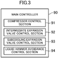
- the main controller (90) of the heat source-side unit (11) includes a compressor control section (91), an intermediate expansion valve control section (92), a subcooling expansion valve control section (93), and a liquid hammer avoidance control section (94).
- the main controller (90) receives values input from the temperature sensors (81a, 81b, 81c, 82) and the pressure sensors (85, 86, 87) provided for the heat source-side unit (11).
- the main controller (90) receives a thermo-off signal from the utilization-side controller (99) of the utilization-side unit (12). A control operation performed by the main controller (90) will be described later.
- the utilization-side unit (12) is provided with a suction air temperature sensor (26).
- the suction air temperature sensor (26) measures the temperature of indoor air that has not passed through the utilization-side heat exchanger (61) yet.
- the utilization-side controller (99) receives a value measured by the suction air temperature sensor (26).
- the utilization-side controller (99) opens and closes the utilization-side solenoid valve (62) in accordance with the value measured by the suction air temperature sensor (26).
- the utilization-side controller (99) outputs the thermo-off signal if the utilization-side solenoid valve (62) is to be closed. An operation performed by the utilization-side controller (99) will be described later.
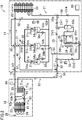
- the refrigeration apparatus (10) operates in a selected one of a normal mode for cooling an internal space or a defrosting mode for melting frost formed on the utilization-side heat exchanger (61).
- a normal mode for cooling an internal space
- a defrosting mode for melting frost formed on the utilization-side heat exchanger (61).
- the normal mode will be described in detail, but the defrosting mode will not be described.
- the four-way switching valve (32) is set to the second state, the utilization-side heat exchanger (61) functions as a condenser, and the heat source-side heat exchanger (33) functions as an evaporator.
- the utilization-side fan (24) stops.
- the refrigerant circuit (20) operating in the normal mode allows the refrigerant to circulate to perform a refrigeration cycle, in which the heat source-side heat exchanger (33) functions as a condenser, and the utilization-side heat exchanger (61) functions as an evaporator.
- the four-way switching valve (32) is set to the first state in the normal mode.
- the main controller (90) controls the subcooling expansion valve (35), the intermediate expansion valves (36a, 36b, 36c), and the heat source-side expansion valve (38). An operation of the main controller (90) will be described later.
- the utilization-side solenoid valves (62) of the utilization-side units (12) are set to the open state.
- the refrigerant discharged from the compressors (31a-31c) passes through the oil separator (41) in the discharge refrigerant pipe (51), then flows into the heat source-side heat exchanger (33) through the four-way switching valve (32), and dissipates heat to the outdoor air in the heat source-side heat exchanger (33) to condense.
- the refrigerant (high-pressure refrigerant) flowing out of the heat source-side heat exchanger (33) sequentially passes through the first heat source-side liquid pipe (53a), the receiver (37), and the second heat source-side liquid pipe (53b) in this order, flows into the first flow paths (34a) of the subcooling heat exchanger (34), and is cooled by the refrigerant flowing through the second flow paths (34b) of the subcooling heat exchanger (34).
- Part of the subcooled liquid refrigerant that has flowed from the first flow paths (34a) of the subcooling heat exchanger (34) into the third heat source-side liquid pipe (53c) flows into the first main injection pipe (54m).
- the remaining part sequentially passes through the heat source-side expansion valve (38) and the liquid-side shutoff valve (VI) in this order, and then flows into the liquid-side connection pipe (14).
- the refrigerant that has flowed into the liquid-side connection pipe (14) is introduced in the utilization-side circuit (23) of the utilization-side unit (12).
- the refrigerant that has flowed into the first utilization-side liquid pipe (71a) passes through the drain pan heater (71b), and then flows into the utilization-side solenoid valve (62) through the second utilization-side liquid pipe (71c).
- the refrigerant that has passed through the utilization-side solenoid valve (62) expands when passing through the utilization-side expansion valve (63), and turns to be a gas-liquid two-phase refrigerant, which then flows into the utilization-side heat exchanger (61).
- the refrigerant that has flowed into the utilization-side heat exchanger (61) absorbs heat from the indoor air to evaporate. As a result, the indoor air is cooled.
- the utilization-side unit (12) sends the indoor air cooled in the utilization-side heat exchanger (61) back to the internal space.
- the refrigerant that has evaporated in the utilization-side heat exchanger (61) flows into the gas-side connection pipe (15) through the utilization-side gas refrigerant pipe (72). Flows of the refrigerant from the utilization-side circuits (23) enter and merge together in the gas-side connection pipe (15). Then, the merged refrigerant flows into the heat source-side circuit (21), sequentially passes through the gas-side shutoff valve (V2) and the four-way switching valve (32) in this order, and thereafter, is sucked into the compressors (31a-31c) through the suction refrigerant pipe (52).
- the refrigerant that has flowed into the first main injection pipe (54m) expands when passing through the subcooling expansion valve (35), and turns to be a gas-liquid two-phase refrigerant, which then flows into the second flow paths (34b) of the subcooling heat exchanger (34), and absorbs heat from the refrigerant (high-pressure refrigerant) flowing through the first flow paths (34a) of the subcooling heat exchanger (34) to evaporate.
- the refrigerant that has flowed into the second main injection pipe (54n) through the second flow paths (34b) of the subcooling heat exchanger (34) is introduced into the intermediate ports of the compressors (31a-31c).
- the utilization-side controller (99) in the utilization-side unit (12) opens and closes the utilization-side solenoid valve (62) in accordance with the value measured by the suction air temperature sensor (26). The operation of this utilization-side controller (99) will be described.
- the utilization-side controller (99) controls the utilization-side solenoid valve (62) such that a value Tr measured by the suction air temperature sensor (26) is in the range of the set internal temperature Tr_set ⁇ 1°C (i.e., Tr_set - 1 ⁇ Tr ⁇ Tr_set + 1).
- the utilization-side solenoid valve (62) is open. While the utilization-side solenoid valve (62) is open, the utilization-side unit (12) is in the cooling state. Specifically, the refrigerant flows into the utilization-side heat exchanger (61) to evaporate. As a result, the indoor air is cooled in the utilization-side heat exchanger (61). While the utilization-side solenoid valve (62) is open, the temperature of the indoor air (i.e., the value Tr measured by the suction air temperature sensor (26)) gradually decreases.
- Tr_set - 1 i.e., Tr ⁇ Tr_set - 1 is met
- the utilization-side controller (99) switches the utilization-side solenoid valve (62) from the open state to the closed state. Switching the utilization-side solenoid valve (62) from the open state to the closed state, the utilization-side controller (99) outputs, to the main controller (90), the thermo-off signal indicating that the utilization-side unit (12) has been suspended.
- the utilization-side solenoid valve (62) While the utilization-side solenoid valve (62) is closed, the utilization-side unit (12) is in the suspended state. Specifically, the flow of a refrigerant through the utilization-side heat exchanger (61) is blocked, and the indoor air is not cooled in the utilization-side heat exchanger (61). While the utilization-side solenoid valve (62) is closed, the temperature of the indoor air (i.e., the value Tr measured by the suction air temperature sensor (26)) gradually increases. If the value Tr measured by the suction air temperature sensor (26) exceeds Tr_set + 1 (i.e., Tr_set + 1 ⁇ Tr is met), the utilization-side controller (99) switches the utilization-side solenoid valve (62) from the closed state to the open state.
- Tr_set + 1 i.e., Tr_set + 1 ⁇ Tr
- the utilization-side controller (99) is configured to be capable of receiving a valve open command output from the main controller (90). The valve open command will be described in detail later.
- the utilization-side controller (99) keeps the utilization-side solenoid valve (62) open until the valve open command is canceled. In other words, during a period from when the valve open command is received to when the valve open command is canceled, the utilization-side controller (99) keeps the utilization-side solenoid valve (62) open even if the value Tr measured by the suction air temperature sensor (26) falls below Tr_set - 1.
- the main controller (90) includes the compressor control section (91), the intermediate expansion valve control section (92), the subcooling expansion valve control section (93), and the liquid hammer avoidance control section (94). Operations performed by the compressor control section (91), the intermediate expansion valve control section (92), the subcooling expansion valve control section (93), and the liquid hammer avoidance control section (94) will be described.
- the main controller (90) operates the four-way switching valve (32) for the switching between the normal mode and the defrosting mode, and controls the rotational speed of the heat source-side fan (22).
- the compressor control section (91) adjusts the operating capacity of the first compressor (31a), and switches the second and third compressors (31b) and (31c) between an on state and an off state, such that the value measured by the suction pressure sensor (86) reaches a predetermined target pressure.
- the evaporating pressure of the refrigerant in the utilization-side heat exchanger (61) increases.
- the low pressure of the refrigeration cycle is substantially equal to the value measured by the suction pressure sensor (86).
- the compressor control section (91) performs an operation to increase the operating capacities of the compressors (31a-31c).
- the compressor control unit (91) performs an operation of increasing the output frequency of the inverter and increasing the operating capacity of the first compressor (31a), and an operation of starting one of the second and third compressors (31b) and (31c) which is stopped.
- the compressor control section (91) performs an operation to reduce the operating capacities of the compressors (31a-31c). Specifically, in this case, the compressor control section (91) performs an operation of gradually reducing the output frequency of the inverter to reduce the operating capacity of the first compressor (31a), and an operation of suspending one of the second and third compressors (31b) and (31c) which is operating.
- the intermediate expansion valve control section (92) adjusts the degrees of opening of the intermediate expansion valves (36a-36c).
- the intermediate expansion valve control section (92) adjusts the degree of opening of the first intermediate expansion valve (36a) in accordance with the values measured by the first discharge refrigerant temperature sensor (81a) and the discharge pressure sensor (85), adjusts the degree of opening of the second intermediate expansion valve (36b) in accordance with the values measured by the second discharge refrigerant temperature sensor (81b) and the discharge pressure sensor (85), and adjusts the degree of opening of the third intermediate expansion valve (36c) in accordance with the values measured by the third discharge refrigerant temperature sensor (81c) and the discharge pressure sensor (85).
- the intermediate expansion valve control section (92) adjusts the degree of opening of the first intermediate expansion valve (36a) in the same way.
- the intermediate expansion valve control section (92) adjusts the degrees of opening of the second and third intermediate expansion valves (36b) and (36c) in the same way.
- the intermediate expansion valve control section (92) performs an operation of increasing the degree of opening of the first intermediate expansion valve (36a) to reduce the value measured by the first discharge refrigerant temperature sensor (81a).
- the intermediate expansion valve control section (92) adjusts the degree of opening of the first intermediate expansion valve (36a) such that the superheat of the refrigerant discharged from the first compressor (31a) reaches a predetermined target discharge superheat.
- the intermediate expansion valve control section (92) calculates the superheat of the refrigerant discharged from the first compressor (31a) using the values measured by the first discharge refrigerant temperature sensor (81a) and the discharge pressure sensor (85). If the calculated superheat exceeds the target discharge superheat, the intermediate expansion valve control section (92) increases the degree of opening of the first intermediate expansion valve (36a). If the calculated superheat falls below the target discharge superheat, the intermediate expansion valve control section (92) reduces the degree of opening of the first intermediate expansion valve (36a).
- the intermediate expansion valve control section (92) adjusts the degree of opening of the associated intermediate expansion valve(s) (36a-36c). If one or more of the compressors (31a-31c) respectively associated with the intermediate expansion valves (36a-36c) are suspending, the intermediate expansion valve control section (92) keeps the associated intermediate expansion valve(s) (36a-36c) fully closed. Specifically, the intermediate expansion valve control section (92) adjusts the degree of opening of the second intermediate expansion valve (36b) while the second compressor (31b) is operating, and keeps the second intermediate expansion valve (36b) fully closed while the second compressor (31b) is suspending. Further, the intermediate expansion valve control section (92) adjusts the degree of opening of the third intermediate expansion valve (36c) while the third compressor (31c) is operating, and keeps the second intermediate expansion valve (36b) fully closed while the second compressor (31b) is suspending.
- the subcooling expansion valve control section (93) adjusts the degree of opening of the subcooling expansion valve (35) in accordance with the temperature of the liquid refrigerant sent from the heat source-side unit (11) to the liquid-side connection pipe (14) during the operation in the normal mode.
- the temperature of the liquid refrigerant sent from the heat source-side unit (11) to the liquid-side connection pipe (14) during the operation in the normal mode is substantially equal to the value measured by the liquid refrigerant temperature sensor (82).
- the subcooling expansion valve control section (93) adjusts the degree of opening of the subcooling expansion valve (35) such that the value measured by the liquid refrigerant temperature sensor (82) reaches a predetermined target liquid refrigerant temperature (e.g., 20°C).
- the degree of subcooling of the liquid refrigerant sent from the heat source-side unit (11) to the liquid-side connection pipe (14) is generally about 0°C to 20°C.
- the subcooling expansion valve control section (93) reduces the degree of opening of the subcooling expansion valve (35), and reduces the temperature of the refrigerant sent from the subcooling expansion valve (35) to the second flow paths (34b) of the subcooling heat exchanger (34).
- the subcooling expansion valve control section (93) increases the degree of opening of the subcooling expansion valve (35), and increases the temperature of the refrigerant sent from the subcooling expansion valve (35) to the second flow paths (34b) of the subcooling heat exchanger (34).
- the liquid hammer avoidance control section (94) performs control to avoid a liquid hammer phenomenon. This control to avoid the liquid hammer phenomenon is performed when the utilization-side unit (12) is switched from the cooling state to the suspended state.
- the liquid hammer avoidance control will be described with reference to the flowchart of FIG. 4 .
- Step ST1 the liquid hammer avoidance control section (94) determines whether or not the liquid hammer avoidance control section (94) has received a thermo-off signal from the utilization-side unit (12). If the main controller (90) has not received the thermo-off signal, no liquid hammer phenomenon occurs, so that the liquid hammer avoidance control section (94) finishes the liquid hammer avoidance control. On the other hand, when the liquid hammer avoidance control section (94) has received the thermo-off signal, the liquid hammer avoidance control section (94) proceeds to Step ST2.
- Step ST2 the liquid hammer avoidance control section (94) outputs a valve open command to the utilization-side controller (99).
- This valve open command is a command signal for causing the utilization-side controller (99) to keep the utilization-side solenoid valve (62) open.
- the utilization-side controller (99) keeps the utilization-side solenoid valve (62) open until the valve open command is canceled.
- Steps ST3 to ST5 correspond to the preparatory operation.
- Step ST3 the liquid hammer avoidance control section (94) sets a target pressure Ps_t which is a target value of the refrigerant pressure of the liquid-side connection pipe (14). More specifically, the liquid hammer avoidance control section (94) reads the measurement value TL of the liquid refrigerant temperature sensor (82). The liquid hammer avoidance control section (94) calculates a saturation pressure of the refrigerant at the measurement value TL using the read measurement value TL and the physical property of the refrigerant, and sets the value of the saturation pressure to the target pressure Ps_t.
- Ps_t is a target value of the refrigerant pressure of the liquid-side connection pipe (14). More specifically, the liquid hammer avoidance control section (94) reads the measurement value TL of the liquid refrigerant temperature sensor (82). The liquid hammer avoidance control section (94) calculates a saturation pressure of the refrigerant at the measurement value TL using the read measurement value TL and the physical property of the refrigerant, and sets the value of
- Step ST4 the liquid hammer avoidance control section (94) reduces the degree of opening of the heat source-side expansion valve (38) so that the value Ps measured by the liquid refrigerant pressure sensor (87) reaches the target pressure Ps_t.
- a reduction amount of the degree of opening of the heat source-side expansion valve (38) in Step ST4 may be a predetermined constant value or a value adjusted in accordance with the value Ps measured by the liquid refrigerant pressure sensor (87) and the target pressure Ps_t.
- the liquid hammer avoidance control section (94) reads the value Ps measured by the liquid refrigerant pressure sensor (87), and compares the read measurement value Ps with the target pressure Ps_t. If the measured value Ps is higher than or equal to the target pressure Ps_t (Ps ⁇ Ps_t), the liquid hammer avoidance control section (94) returns to Step ST4, and further reduces the degree of opening of the heat source-side expansion valve (38). On the other hand, if the measured value Ps is lower than the target pressure Ps_t (Ps ⁇ Ps_t), it can be determined that the refrigerant flowing through the liquid-side connection pipe (14) is in the gas-liquid two-phase state. In this case, the liquid hammer avoidance control section (94) proceeds to Step ST6, and fully closes the heat source-side expansion valve (38).
- the liquid hammer avoidance control section (94) reads the value LP measured by the suction pressure sensor (86), and compares the read measurement value LP with the lower limit pressure LP_min stored in advance. If the measured value LP is higher than or equal to the lower limit pressure LP min (LP ⁇ LP_min), the liquid hammer avoidance control section (94) stands by as it is. On the other hand, if the measured value LP is lower than the lower limit pressure LP_min (LP ⁇ LP_min), the liquid hammer avoidance control section (94) proceeds to Step ST8, and stops the compressors (31a-31c).
- Step ST9 the liquid hammer avoidance control section (94) cancels the valve open command output in Step ST2, and finishes the liquid hammer avoidance control.
- the utilization-side controller (99) of the utilization-side unit (12) outputs the thermo-off signal.
- Tr measured by the suction air temperature sensor (26) already falls below Tr_set - 1. Therefore, when the liquid hammer avoidance control section (94) cancels the valve open command, the utilization-side controller (99) of the utilization-side unit (12) closes the utilization-side solenoid valve (62).
- the liquid hammer avoidance control section (94) of the main controller (90) performs the liquid hammer avoidance control.
- the liquid hammer avoidance control section (94) fully closes the heat source-side expansion valve (38) upon receiving the thermo-off signal from the utilization-side unit (12), and thereafter, stops the compressors (31a-31c) when the measurement value LP of the suction pressure sensor (86) falls below the lower limit pressure LP_min, and cancels the valve open command.
- this embodiment can reduce the density of the refrigerant present toward the inlet side of the utilization-side solenoid valve (62) in the closed state, thereby reducing the risk of a liquid hammer phenomenon that occurs upon opening the utilization-side solenoid valve (62).
- the liquid hammer avoidance control section (94) of this embodiment performs the preparatory operation, and then sets the heat source-side expansion valve (38) in the fully-closed state.
- the liquid hammer avoidance control section (94) narrows the opening of the heat source-side expansion valve (38) so that the refrigerant flowing through the liquid-side connection pipe (14) turns to be a gas-liquid two-phase refrigerant, and thereafter, sets the heat source-side expansion valve (38) into a fully closed state.
- both of the liquid refrigerant and the gas refrigerant are present in the liquid-side connection pipe (14).
- a change in the volume of the gas refrigerant reduces a pressure variation at the time of opening the utilization-side solenoid valve (62).
- the presence of the gas refrigerant in the liquid-side connection pipe (14) makes it possible to further reduce the risk of a liquid hammer phenomenon that occurs upon opening the utilization-side solenoid valve (62).
- a second embodiment will be described.
- the following description of a refrigeration apparatus (10) of this embodiment will be focused on differences from the refrigeration apparatus (10) of the first embodiment.
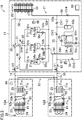
- the refrigeration apparatus (10) of this embodiment includes a plurality of (two in this embodiment) utilization-side units (12A, 12B).
- Each utilization-side unit (12) is a so-called unit cooler.
- the two utilization-side units (12A, 12B) shown in FIG. 5 are installed in an interior space of a single refrigerator (i.e., a single space). Note that the number of the utilization-side units (12) is merely an example.
- the two utilization-side units (12A, 12B) are arranged in parallel in a refrigerant circuit (20).
- a liquid-side connection pipe (14) is connected to the liquid-side end of a utilization-side circuit (23) of each of the utilization-side units (12A, 12B), and a gas-side connection pipe (15) is connected to the gas-side end of the utilization-side circuit (23) of each of the utilization-side units (12A, 12B).
- the first utilization-side unit (12A) includes a utilization-side controller (99) and a suction air temperature sensor (26).
- This utilization-side controller (99) controls a utilization-side solenoid valve (62) of the first utilization-side unit (12A) and a utilization-side solenoid valve (62) of the second utilization-side unit (12B).
- Tr_set - 1 i.e., Tr ⁇ Tr_set - 1 is met
- the utilization-side controller (99) switches the utilization-side solenoid valve (62) of each of the utilization-side units (12A, 12B) from the open state to the closed state.
- Tr ⁇ Tr_set - 1 the utilization-side controller
- Tr_set + 1 i.e., Tr > Tr_set + 1 is met
- the utilization-side controller (99) switches the utilization-side solenoid valve (62) of each of the utilization-side units (12A, 12B) from the closed state to the open state.
- Tr > Tr_set + 1 the utilization-side controller
- the main controller (90) of the refrigeration apparatus (10) of this embodiment also includes the liquid hammer avoidance control section (94).
- the liquid hammer avoidance control section (94) performs the liquid hammer avoidance control shown in FIG. 4 .
- the present invention is useful for a refrigeration apparatus which allows a refrigerant to circulate through a refrigerant circuit to perform a refrigeration cycle.
Landscapes
- Engineering & Computer Science (AREA)
- Physics & Mathematics (AREA)
- Mechanical Engineering (AREA)
- Thermal Sciences (AREA)
- General Engineering & Computer Science (AREA)
- Air Conditioning Control Device (AREA)
- Compression-Type Refrigeration Machines With Reversible Cycles (AREA)
- Devices That Are Associated With Refrigeration Equipment (AREA)
Abstract
Description
- The present invention relates to a refrigeration apparatus that circulates a refrigerant through a refrigerant circuit to perform a refrigeration cycle.
- A refrigerant circuit of a refrigeration apparatus that performs a refrigeration cycle may be provided with a solenoid valve to control the flow of a refrigerant. A general solenoid valve interrupts the passage of electric current through a solenoid for switching between an open state and a closed state.
- The refrigerant circuit of the refrigeration apparatus includes a pipe through which a high-pressure liquid refrigerant flows. The pipe may be provided with a solenoid valve. When closed, the solenoid valve blocks the flow of the high-pressure liquid refrigerant. If the solenoid valve opens when there is a large differential pressure between both sides of the solenoid valve, a substantially incompressible liquid refrigerant having a relatively high density suddenly flows downstream of the solenoid valve, resulting in a liquid hammer phenomenon. This may break a pipe, an expansion valve, or any other component.
- Patent Document 1 discloses that, in order to prevent a liquid hammer phenomenon that occurs when the solenoid valve opens, a pipe through which a liquid refrigerant flows is heated with an electric heater. Specifically, heating the pipe with the electric heater allows part of the refrigerant in the pipe to evaporate, thereby producing a compressible gas refrigerant in the pipe. This reduces the degree of the sudden increase in the internal pressure of the pipe upon opening the solenoid valve.
- [Patent Document 1] Japanese Unexamined Patent Publication No.
H11-325654 - The refrigeration apparatus of Patent Document 1 described above needs to include the electric heater for heating the pipe in order to prevent the liquid hammer phenomenon caused upon opening the solenoid valve. This increases the number of parts of the refrigeration apparatus, resulting in an increase in the manufacturing cost. While the solenoid valve is closed, the electric heater needs to keep heating the pipe. This may increase power consumption of the refrigeration apparatus, resulting in the increase in the running cost of the refrigeration apparatus.
- In view of the foregoing background, it is therefore an object of the present invention to curb the increases in the manufacturing and running costs of a refrigeration apparatus, and reduce the possibility of a liquid hammer phenomenon that occurs upon opening a solenoid valve.
- A first aspect of the present disclosure is directed to a refrigeration apparatus which includes a refrigerant circuit (20) in which a heat source-side unit (11) and a utilization-side unit (12) are connected together through a liquid-side connection pipe (14) and a gas-side connection pipe (15), the refrigeration apparatus allowing a refrigerant to circulate through the refrigerant circuit (20) to perform a refrigeration cycle. The heat source-side unit (11) includes a compressor (31a-31c), a heat source-side heat exchanger (33), and a heat source-side expansion valve (38) provided for a pipe (53c) sending the refrigerant condensed in the heat source-side heat exchanger (33) to the liquid-side connection pipe (14), the utilization-side unit (12) includes a utilization-side heat exchanger (61), a utilization-side expansion valve (63), and a utilization-side solenoid valve (62), which are arranged in series. The utilization-side unit (12) is switchable between a cooling state where the utilization-side solenoid valve (62) opens to allow the utilization-side heat exchanger (61) to function as an evaporator, and a suspended state where the utilization-side solenoid valve (62) is closed to block the refrigerant from flowing through the utilization-side heat exchanger (61). The refrigeration apparatus further includes a controller (90) configured to close the heat source-side expansion valve (38) when the utilization-side unit (12) is switched from the cooling state to the suspended state, and then stop the compressor (31a-31c) and close the utilization-side solenoid valve (62).
- In the first aspect, the heat source-side unit (11) and a plurality of utilization-side units (12) are provided for the refrigerant circuit (20). The refrigerant condensed in the heat source-side heat exchanger (33) of the heat source-side unit (11) flows into the utilization-side units (12) through the liquid-side connection pipe (14). The refrigerant supplied through the liquid-side connection pipe (14) to the utilization-side units (12) expands when passing through the associated utilization-side expansion valve (63), and then flows into the associated utilization-side heat exchanger (61) to evaporate. In the utilization-side heat exchanger (61), the refrigerant cools a target to be cooled, such as air. The refrigerant evaporated in the utilization-side heat exchanger (61) of the utilization-side unit (12) flows into the heat source-side unit (11) through the gas-side connection pipe (15), and thereafter, is sucked into the compressor (31a-31c) to be compressed.
- In the first aspect, when the utilization-side unit (12) is switched from a cooling state to a suspended state, the controller (90) performs a predetermined operation. The operation of this controller (90) will be described below. The controller (90) first closes the heat source-side expansion valve (38). At this time, since the compressor (31a-31c) is operating, the pressure of the refrigerant in the liquid-side connection pipe (14) gradually decreases. The controller (90) then stops the compressor (31a-31c) and closes the utilization-side solenoid valve (62). Therefore, when the utilization-side solenoid valve (62) is closed, the density of the refrigerant present toward the inlet side of the utilization-side solenoid valve (62) is lowered as compared with the case where the utilization-side unit (12) is in the cooling state.
- According to a second aspect of the present disclosure, when the utilization-side unit (12) is switched from the cooling state to the suspended state, the controller (90) is configured to perform a preparatory operation before closing the heat source-side expansion valve (38), the preparatory operation reducing a degree of opening of the heat source-side expansion valve (38) so that a refrigerant flowing through the liquid-side connection pipe (14) is brought into a gas-liquid two-phase state.
- When the utilization-side unit (12) is switched from the cooling state to the suspended state, the controller (90) of the second aspect closes the heat source-side expansion valve (38) after performing the preparatory operation. In the preparatory operation, the controller (90) reduces the degree of opening of the heat source-side expansion valve (38) so that the refrigerant flowing through the liquid-side connection pipe (14) turns to be a gas-liquid two-phase refrigerant. Therefore, when the heat source-side expansion valve (38) is closed and then the utilization-side solenoid valve (62) is closed, both of the liquid refrigerant and the gas refrigerant are present in the liquid-side connection pipe (14).
- According to a third aspect of the present disclosure, the heat source-side unit (11) includes: a liquid-side pressure sensor (87) which measures a pressure of the refrigerant sent from the heat source-side expansion valve (38) to the liquid-side connection pipe (14); and a liquid-side temperature sensor (82) which measures a temperature of the refrigerant sent from the heat source-side expansion valve (38) to the liquid-side connection pipe (14), and the controller (90) is configured to perform, as the preparatory operation, an operation of reducing the degree of opening of the heat source-side expansion valve (38) so that the pressure measured by the liquid-side pressure sensor (87) becomes lower than a saturation pressure of the refrigerant at the temperature measured by the liquid-side temperature sensor (82).
- In the third aspect, the controller (90) performs the preparatory operation using the pressure measured by the liquid-side pressure sensor (87) and the temperature measured by the liquid-side temperature sensor (82). When the controller (90) performs the preparatory operation and the pressure measured by the liquid-side pressure sensor (87) becomes lower than the saturation pressure of the refrigerant at the temperature measured by the liquid-side temperature sensor (82), the refrigerant flowing through the liquid-side connection pipe (14) is in a gas-liquid two-phase state.
- In the first aspect, when the utilization-side unit (12) is switched from the cooling state to the suspended state, the controller (90) performs a predetermined operation. Therefore, when the utilization-side solenoid valve (62) is closed, the density of the refrigerant present toward the inlet side of the utilization-side solenoid valve (62) is lowered as compared with the case where the utilization-side unit (12) is in the cooling state.
- The lower the density of the refrigerant present toward the inlet side of the utilization-side solenoid valve (62) in the closed state is, the more the possibility of the adverse effect caused by the liquid hammer phenomenon upon opening the utilization-side solenoid valve (62) decreases. On the other hand, according to the first aspect, the density of the refrigerant present toward the inlet side of the utilization-side solenoid valve (62) can be reduced in advance with the pressure of the refrigerant in the liquid-side connection pipe (14) reduced before the utilization-side solenoid valve (62) is closed. Thus, this aspect can reduce the density of the refrigerant present toward the inlet side of the utilization-side solenoid valve (62) in the closed state, thereby reducing the risk of a liquid hammer phenomenon that occurs upon opening the utilization-side solenoid valve (62).
- When the utilization-side unit (12) is switched from the cooling state to the suspended state, the controller (90) according to the second aspect closes the heat source-side expansion valve (38) after performing the preparatory operation. Therefore, when the utilization-side solenoid valve (62) is closed after the heat source-side expansion valve (38) is closed, a gas refrigerant having compressibility is present in the liquid-side connection pipe (14). In the presence of the gas refrigerant in the liquid-side connection pipe (14), a change in the volume of the gas refrigerant reduces a pressure variation at the time of opening the utilization-side solenoid valve (62). Hence, in this aspect, the gas refrigerant present in the liquid-side connection pipe (14) can further reduce the risk of a liquid hammer phenomenon that occurs upon opening the utilization-side solenoid valve (62).
- According to the third aspect, the controller (90) performs the preparatory operation using the values measured by the liquid-side pressure sensor (87) and the liquid-side temperature sensor (82), so that the refrigerant flowing through the liquid-side connection pipe (14) can be reliably brought into the gas-liquid two-phase state.
-
-
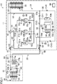
FIG. 1 is a refrigerant circuit diagram showing a schematic configuration for a refrigeration apparatus according to a first embodiment. -
FIG. 2 is a refrigerant circuit diagram showing a refrigeration apparatus in a normal mode. -
FIG. 3 is a block diagram showing a configuration for a main controller. -
FIG. 4 is a flowchart showing an operation performed by a liquid hammer avoidance control section of the main controller. -
FIG. 5 is a refrigerant circuit diagram showing a schematic configuration for a refrigeration apparatus according to a second embodiment. - Embodiments of the present invention will be described in detail with reference to the drawings. Note that the following embodiments and variations are merely beneficial examples in nature, and are not intended to limit the scope, applications, or use of the invention.
- A first embodiment will be described. A refrigeration apparatus (10) according to this embodiment is used to cool an internal space in a refrigerator.
- As shown in
FIG. 1 , the refrigeration apparatus (10) includes a single heat source-side unit (11) and a single utilization-side unit (12). The heat source-side unit (11) is a so-called outdoor unit, and is installed outdoors. The utilization-side unit (12) is a so-called unit cooler, and is installed in the internal space of the refrigerator. - The heat source-side unit (11) is provided with a heat source-side circuit (21), a heat source-side fan (22), and a main controller (90). Meanwhile, the utilization-side unit (12) is provided with a utilization-side circuit (23), a utilization-side fan (24), a drain pan (25), and a utilization-side controller (99).
- The refrigeration apparatus (10) includes a refrigerant circuit (20) in which the heat source-side circuit (21) of the heat source-side unit (11) and the utilization-side circuit (23) of the utilization-side unit (12) are connected together through a liquid-side connection pipe (14) and a gas-side connection pipe (15). The refrigerant circuit (20) allows a refrigerant to circulate therethrough to perform a vapor compression refrigeration cycle.
- The heat source-side circuit (21) has a liquid-side end and a gas-side end respectively provided with a liquid-side shutoff valve (VI) and a gas-side shutoff valve (V2). The liquid-side connection pipe (14) provides connection between the liquid-side shutoff valve (VI) of the heat source-side circuit (21) and the liquid-side end of the utilization-side circuit (23). The gas-side connection pipe (15) provides connection between the gas-side shutoff valve (V2) of the heat source-side circuit (21) and the gas-side end of the utilization-side circuit (23).
- The heat source-side circuit (21) includes first through third compressors (31a, 31b, 31c), a four-way switching valve (32), a heat source-side heat exchanger (33), a subcooling heat exchanger (34), a subcooling expansion valve (35), first through third intermediate expansion valves (36a, 36b, 36c), a receiver (37), a heat source-side expansion valve (38), first through third check valves (CV1-CV3), and an oil separator (41). The heat source-side circuit (21) is provided with a discharge refrigerant pipe (51), a suction refrigerant pipe (52), a heat source-side liquid refrigerant pipe (53), an injection pipe (54), a first connection pipe (55), a second connection pipe (56), and an oil return pipe (57). Note that the number of the compressors (31a-31c) of the heat source-side unit (11) is merely an example.
- The first through third compressors (31a, 31b, 31c) are all hermetic scroll compressors. Each compressor (31a-31c) has a suction port, an intermediate port, and a discharge port. The compressor (31a-31c) compresses a refrigerant sucked therein through the suction port, and discharges the compressed refrigerant through the discharge port. The intermediate port of the compressor (31a-31c) is used to introduce a refrigerant into a compression chamber in the course of compression.
- The first compressor (31a) has a variable capacity. An electric motor of the first compressor (31a) is supplied with power from an inverter outside the drawing. Changing the output frequency of the inverter triggers a change in the rotational speed of the first compressor (31a). This causes the operating capacity of the first compressor (31a) to vary. On the other hand, the second and third compressors (31b) and (31c) each have a fixed capacity. The second and third compressors (31b) and (31c) rotate at a constant rotational speed.
- The four-way switching valve (32) is switchable between a first state (indicated by the solid curves shown in
FIG. 1 ) and a second state (indicated by the dashed curves shown inFIG. 1 ). In the first state, a first port communicates with a third port, and a second port communicates with a fourth port. In the second state, the first port communicates with the fourth port, and the second port communicates with the third port. - The first port of the four-way switching valve (32) is connected to the discharge ports of the compressors (31a-31c) through the discharge refrigerant pipe (51), and the second port thereof is connected to the suction ports of the compressors (31a-31c) through the suction refrigerant pipe (52). The third port of the four-way switching valve (32) is connected to the gas-side end of the heat source-side heat exchanger (33), and the fourth port thereof is connected to the gas-side shutoff valve (V2).
- The discharge refrigerant pipe (51) includes the same number of (three in this embodiment) discharge pipes (51a, 51b, 51c) as the compressors (31a-31c), and a single discharge collection pipe (51d). One end of the first discharge pipe (51a) is connected to the discharge port of the first compressor (31a), one end of the second discharge pipe (51b) is connected to the discharge port of the second compressor (31b), and one end of the third discharge pipe (51c) is connected to the discharge port of the third compressor (31c). The other end of each discharge pipe (51a, 51b, 51c) is connected to one end of the discharge collection pipe (51d). The other end of the discharge collection pipe (51d) is connected to the first port of the four-way switching valve (32).
- The suction refrigerant pipe (52) includes the same number of (three in this embodiment) suction pipes (52a, 52b, 52c) as the compressors (31a-31c), and a single main suction pipe (52d). One end of the first suction pipe (52a) is connected to the suction port of the first compressor (31a), one end of the second suction pipe (52b) is connected to the suction port of the second compressor (31b), and one end of the third suction pipe (52c) is connected to the suction port of the third compressor (31c). The other end of each suction pipe (52a, 52b, 52c) is connected to one end of the main suction pipe (52d). The other end of the main suction pipe (52d) is connected to the second port of the four-way switching valve (32).
- The heat source-side heat exchanger (33) is a cross-fin, fin-and-tube heat exchanger, and exchanges heat between a refrigerant and outdoor air. The heat source-side heat exchanger (33) has a liquid-side end connected to the heat source-side liquid refrigerant pipe (53), and a gas-side end connected to the third port of the four-way switching valve (32). The heat source-side fan (22) for supplying the outdoor air to the heat source-side heat exchanger (33) is disposed near the heat source-side heat exchanger (33).
- The subcooling heat exchanger (34) is a so-called plate-type heat exchanger. The subcooling heat exchanger (34) has a plurality of first flow paths (34a) and a plurality of second flow paths (34b). The subcooling heat exchanger (34) exchanges heat between a refrigerant flowing through the first flow paths (34a) and a refrigerant flowing through the second flow paths (34b).
- The heat source-side liquid refrigerant pipe (53) has one end connected to the heat source-side heat exchanger (33), and the other end connected to the liquid-side shutoff valve (VI). The heat source-side liquid refrigerant pipe (53) includes three heat source-side liquid pipes (53a, 53b, 53c). The first heat source-side liquid pipe (53a) provides connection between the liquid-side end of the heat source-side heat exchanger (33) and the inlet of the receiver (37). The second heat source-side liquid pipe (53b) provides connection between the outlet of the receiver (37) and the inlets of the first flow paths (34a) of the subcooling heat exchanger (34). The third heat source-side liquid pipe (53c) provides connection between the outlets of the first flow paths (34a) of the subcooling heat exchanger (34) and the liquid-side shutoff valve (VI).
- The first heat source-side liquid pipe (53a) is provided with a first check valve (CV1). The first check valve (CV1) allows the refrigerant to flow from the heat source-side heat exchanger (33) toward the receiver (37), and blocks the refrigerant from flowing in the reverse direction.
- The third heat source-side liquid pipe (53c) is provided with the heat source-side expansion valve (38) and a second check valve (CV2) arranged in this order from the subcooling heat exchanger (34) toward the liquid-side shutoff valve (VI). The heat source-side expansion valve (38) is an electric expansion valve having a variable degree of opening. The second check valve (CV2) allows the refrigerant to flow from the subcooling heat exchanger (34) toward the liquid-side shutoff valve (VI), and blocks the refrigerant from flowing in the reverse direction.
- The injection pipe (54) includes two main injection pipes (54m, 54n), and three injection branch pipes (54a, 54b, 54c).
- The first main injection pipe (54m) has one end connected to a portion of the third heat source-side liquid pipe (53c) between the subcooling heat exchanger (34) and the heat source-side expansion valve (38), and the other end connected the inlets of the second flow paths (34b) of the subcooling heat exchanger (34). The first main injection pipe (54m) constitutes a subcooling pipe. The first main injection pipe (54m) is provided with the subcooling expansion valve (35). One end of the second main injection pipe (54n) is connected to the outlets of the second flow paths (34b) of the subcooling heat exchanger (34). The other end of the second main injection pipe (54n) is connected to one end of each injection branch pipe (54a, 54b, 54c).
- The other ends of the first, second, and third injection branch pipes (54a), (54b), and (54c) are respectively connected to the intermediate ports of the first, second, and third compressors (31a), (31b), and (31c). The injection branch pipes (54a-54c) are respectively provided with the intermediate expansion valves (36a, 36b, 36c). Each intermediate expansion valve (36a-36c) is an electric expansion valve having a variable degree of opening.
- One end of the first connection pipe (55) is connected to a portion of the third heat source-side liquid pipe (53c) between the second check valve (CV2) and the liquid-side shutoff valve (VI), and the other end thereof is connected to a portion of the first heat source-side liquid pipe (53a) between the first check valve (CV1) and the receiver (37). The first connection pipe (55) is provided with a third check valve (CV3). The third check valve (CV3) allows the refrigerant to flow from the one end toward the other end of the first connection pipe (55), and blocks the refrigerant from flowing in the reverse direction.
- One end of the second connection pipe (56) is connected to a portion of the third heat source-side liquid pipe (53c) between the heat source-side expansion valve (38) and the second check valve (CV2), and the other end thereof is connected to a portion of the first heat source-side liquid pipe (53a) between the heat source-side heat exchanger (33) and the first check valve (CV1). The second connection pipe (56) is provided with a fourth check valve (CV4). The fourth check valve (CV4) allows the refrigerant to flow from the one end toward the other end of the second connection pipe (56), and blocks the refrigerant from flowing in the reverse direction.
- The oil separator (41) is provided for the discharge collection pipe (51d) of the discharge refrigerant pipe (51). A gas refrigerant containing refrigerating machine oil in the form of mist is discharged from the compressors (31a-31c). The oil separator (41) separates the refrigerating machine oil from the refrigerant discharged from the compressors (31a-31c).
- The oil return pipe (57) is used to return the refrigerating machine oil from the oil separator (41) to the compressors (31a-31c). The oil return pipe (57) has one end connected to the oil separator (41), and the other end connected to the second main injection pipe (54n). The oil return pipe (57) is provided with a capillary tube (42).
- The heat source-side circuit (21) is provided with a plurality of temperature sensors (81a, 81b, 81c, 82) and a plurality of pressure sensors (85, 86, 87).
- The discharge pipes (51a, 51b, 51c) of the discharge refrigerant pipe (51) are respectively provided with first through third discharge refrigerant temperature sensors (81a, 81b, 81c). The first discharge refrigerant temperature sensor (81a) is attached to the first discharge pipe (51a) to measure the temperature of the refrigerant discharged from the first compressor (31a). The second discharge refrigerant temperature sensor (81b) is attached to the second discharge pipe (51b) to measure the temperature of the refrigerant discharged from the second compressor (31b). The third discharge refrigerant temperature sensor (81c) is attached to the third discharge pipe (51c) to measure the temperature of the refrigerant discharged from the third compressor (31c).
- The heat source-side liquid refrigerant pipe (53) is provided with a liquid refrigerant temperature sensor (82). The liquid refrigerant temperature sensor (82) is attached to the third heat source-side liquid pipe (53c) to measure the temperature of the refrigerant flowing through the third heat source-side liquid pipe (53c). The liquid refrigerant temperature sensor (82) is a liquid-side temperature sensor.
- A discharge pressure sensor (85) is connected to the discharge collection pipe (51d) of the discharge refrigerant pipe (51) to measure the pressure of the refrigerant discharged from the compressors (31a-31c). A suction pressure sensor (86) is connected to the main suction pipe (52d) of the suction refrigerant pipe (52) to measure the pressure of the refrigerant yet to be sucked into the compressors (31a-31c). A liquid refrigerant pressure sensor (87) is connected to the third heat source-side liquid pipe (53c) of the heat source-side liquid refrigerant pipe (53) to measure the pressure of the refrigerant flowing through the third heat source-side liquid pipe (53c). The liquid refrigerant pressure sensor (87) is a liquid-side pressure sensor.
- The utilization-side circuit (23) includes a utilization-side heat exchanger (61), a drain pan heater (71b), a utilization-side solenoid valve (62), and a utilization-side expansion valve (63). The utilization-side circuit (23) is provided with a utilization-side liquid refrigerant pipe (71) and a utilization-side gas refrigerant pipe (72).
- The utilization-side heat exchanger (61) is a cross-fin, fin-and-tube heat exchanger, and exchanges heat between the refrigerant and the indoor air. The utilization-side fan (24) for supplying the indoor air to the utilization-side heat exchanger (61) is disposed near the utilization-side heat exchanger (61).
- The drain pan heater (71b) is configured as a pipe of the drain pan (25) disposed below the utilization-side heat exchanger (61). The drain pan heater (71b) is used to heat the drain pan (25) to prevent drain water from being frozen.
- The utilization-side liquid refrigerant pipe (71) includes a first utilization-side liquid pipe (71a) and a second utilization-side liquid pipe (71c). One end of the first utilization-side liquid pipe (71a) is connected to the liquid-side connection pipe (14), and the other end thereof is connected to one end of the drain pan heater (71b). The one end of the first utilization-side liquid pipe (71a) constitutes the liquid-side end of the utilization-side circuit (23). The second utilization-side liquid pipe (71c) has one end connected to the other end of the drain pan heater (71b), and the other end connected to the liquid-side end of the utilization-side heat exchanger (61).
- One end of the utilization-side gas refrigerant pipe (72) is connected to the gas-side end of the utilization-side heat exchanger (61), and the other end thereof is connected to the gas-side connection pipe (15). The other end of the utilization-side gas refrigerant pipe (72) constitutes the gas-side end of the utilization-side circuit (23).
- The utilization-side solenoid valve (62) and the utilization-side expansion valve (63) are provided for the second utilization-side liquid pipe (71c) of the utilization-side liquid refrigerant pipe (71). The utilization-side expansion valve (63) is disposed at a portion of the second utilization-side liquid pipe (71c) between the utilization-side solenoid valve (62) and the utilization-side heat exchanger (61).
- The utilization-side solenoid valve (62) interrupts the passage of electric current through a solenoid for switching between an open state and a closed state. While the utilization-side solenoid valve (62) is in the open state, the utilization-side unit (12) is in a cooling state where the utilization-side heat exchanger (61) functions as an evaporator to cool the indoor air. While the utilization-side solenoid valve (62) is in the closed state, the utilization-side unit (12) is in a suspended state where the flow of the refrigerant through the utilization-side heat exchanger (61) is blocked.
- The utilization-side expansion valve (63) is an externally equalized thermostatic expansion valve. A sensing bulb (63a) of the utilization-side expansion valve (63) is provided near one end of the utilization-side gas refrigerant pipe (72) (near the end toward the utilization-side heat exchanger (61)). An equalizer (63b) of the utilization-side expansion valve (63) is connected to a portion of the utilization-side gas refrigerant pipe (72) near one end thereof.
- As shown in
FIG. 2 , the main controller (90) of the heat source-side unit (11) includes a compressor control section (91), an intermediate expansion valve control section (92), a subcooling expansion valve control section (93), and a liquid hammer avoidance control section (94). The main controller (90) receives values input from the temperature sensors (81a, 81b, 81c, 82) and the pressure sensors (85, 86, 87) provided for the heat source-side unit (11). The main controller (90) receives a thermo-off signal from the utilization-side controller (99) of the utilization-side unit (12). A control operation performed by the main controller (90) will be described later. - The utilization-side unit (12) is provided with a suction air temperature sensor (26). The suction air temperature sensor (26) measures the temperature of indoor air that has not passed through the utilization-side heat exchanger (61) yet. The utilization-side controller (99) receives a value measured by the suction air temperature sensor (26). The utilization-side controller (99) opens and closes the utilization-side solenoid valve (62) in accordance with the value measured by the suction air temperature sensor (26). The utilization-side controller (99) outputs the thermo-off signal if the utilization-side solenoid valve (62) is to be closed. An operation performed by the utilization-side controller (99) will be described later.
- The refrigeration apparatus (10) operates in a selected one of a normal mode for cooling an internal space or a defrosting mode for melting frost formed on the utilization-side heat exchanger (61). Here, the normal mode will be described in detail, but the defrosting mode will not be described.
- In the defrosting mode, the four-way switching valve (32) is set to the second state, the utilization-side heat exchanger (61) functions as a condenser, and the heat source-side heat exchanger (33) functions as an evaporator. In the defrosting mode, the utilization-side fan (24) stops.
- The operation of the refrigeration apparatus (10) in the normal mode will be described with reference to
FIG. 2 . The refrigerant circuit (20) operating in the normal mode allows the refrigerant to circulate to perform a refrigeration cycle, in which the heat source-side heat exchanger (33) functions as a condenser, and the utilization-side heat exchanger (61) functions as an evaporator. - The operation in the normal mode in which both of the utilization-side units (12) are in the cooling state and all the compressors (31a-31c) are operating will now be exemplified.
- As shown in
FIG. 2 , the four-way switching valve (32) is set to the first state in the normal mode. The main controller (90) controls the subcooling expansion valve (35), the intermediate expansion valves (36a, 36b, 36c), and the heat source-side expansion valve (38). An operation of the main controller (90) will be described later. In the case shown inFIG. 2 , the utilization-side solenoid valves (62) of the utilization-side units (12) are set to the open state. - The refrigerant discharged from the compressors (31a-31c) passes through the oil separator (41) in the discharge refrigerant pipe (51), then flows into the heat source-side heat exchanger (33) through the four-way switching valve (32), and dissipates heat to the outdoor air in the heat source-side heat exchanger (33) to condense. The refrigerant (high-pressure refrigerant) flowing out of the heat source-side heat exchanger (33) sequentially passes through the first heat source-side liquid pipe (53a), the receiver (37), and the second heat source-side liquid pipe (53b) in this order, flows into the first flow paths (34a) of the subcooling heat exchanger (34), and is cooled by the refrigerant flowing through the second flow paths (34b) of the subcooling heat exchanger (34). Part of the subcooled liquid refrigerant that has flowed from the first flow paths (34a) of the subcooling heat exchanger (34) into the third heat source-side liquid pipe (53c) flows into the first main injection pipe (54m). The remaining part sequentially passes through the heat source-side expansion valve (38) and the liquid-side shutoff valve (VI) in this order, and then flows into the liquid-side connection pipe (14).
- The refrigerant that has flowed into the liquid-side connection pipe (14) is introduced in the utilization-side circuit (23) of the utilization-side unit (12). In the utilization-side circuit (23), the refrigerant that has flowed into the first utilization-side liquid pipe (71a) passes through the drain pan heater (71b), and then flows into the utilization-side solenoid valve (62) through the second utilization-side liquid pipe (71c). The refrigerant that has passed through the utilization-side solenoid valve (62) expands when passing through the utilization-side expansion valve (63), and turns to be a gas-liquid two-phase refrigerant, which then flows into the utilization-side heat exchanger (61). The refrigerant that has flowed into the utilization-side heat exchanger (61) absorbs heat from the indoor air to evaporate. As a result, the indoor air is cooled. The utilization-side unit (12) sends the indoor air cooled in the utilization-side heat exchanger (61) back to the internal space.
- The refrigerant that has evaporated in the utilization-side heat exchanger (61) flows into the gas-side connection pipe (15) through the utilization-side gas refrigerant pipe (72). Flows of the refrigerant from the utilization-side circuits (23) enter and merge together in the gas-side connection pipe (15). Then, the merged refrigerant flows into the heat source-side circuit (21), sequentially passes through the gas-side shutoff valve (V2) and the four-way switching valve (32) in this order, and thereafter, is sucked into the compressors (31a-31c) through the suction refrigerant pipe (52).
- Meanwhile, the refrigerant that has flowed into the first main injection pipe (54m) expands when passing through the subcooling expansion valve (35), and turns to be a gas-liquid two-phase refrigerant, which then flows into the second flow paths (34b) of the subcooling heat exchanger (34), and absorbs heat from the refrigerant (high-pressure refrigerant) flowing through the first flow paths (34a) of the subcooling heat exchanger (34) to evaporate. The refrigerant that has flowed into the second main injection pipe (54n) through the second flow paths (34b) of the subcooling heat exchanger (34) is introduced into the intermediate ports of the compressors (31a-31c).
- As described above, the utilization-side controller (99) in the utilization-side unit (12) opens and closes the utilization-side solenoid valve (62) in accordance with the value measured by the suction air temperature sensor (26). The operation of this utilization-side controller (99) will be described.
- The utilization-side controller (99) controls the utilization-side solenoid valve (62) such that a value Tr measured by the suction air temperature sensor (26) is in the range of the set internal temperature Tr_set ± 1°C (i.e., Tr_set - 1 ≤ Tr ≤ Tr_set + 1).
- Suppose that the utilization-side solenoid valve (62) is open. While the utilization-side solenoid valve (62) is open, the utilization-side unit (12) is in the cooling state. Specifically, the refrigerant flows into the utilization-side heat exchanger (61) to evaporate. As a result, the indoor air is cooled in the utilization-side heat exchanger (61). While the utilization-side solenoid valve (62) is open, the temperature of the indoor air (i.e., the value Tr measured by the suction air temperature sensor (26)) gradually decreases. If the value Tr measured by the suction air temperature sensor (26) falls below Tr_set - 1 (i.e., Tr < Tr_set - 1 is met), the utilization-side controller (99) switches the utilization-side solenoid valve (62) from the open state to the closed state. Switching the utilization-side solenoid valve (62) from the open state to the closed state, the utilization-side controller (99) outputs, to the main controller (90), the thermo-off signal indicating that the utilization-side unit (12) has been suspended.
- While the utilization-side solenoid valve (62) is closed, the utilization-side unit (12) is in the suspended state. Specifically, the flow of a refrigerant through the utilization-side heat exchanger (61) is blocked, and the indoor air is not cooled in the utilization-side heat exchanger (61). While the utilization-side solenoid valve (62) is closed, the temperature of the indoor air (i.e., the value Tr measured by the suction air temperature sensor (26)) gradually increases. If the value Tr measured by the suction air temperature sensor (26) exceeds Tr_set + 1 (i.e., Tr_set + 1 < Tr is met), the utilization-side controller (99) switches the utilization-side solenoid valve (62) from the closed state to the open state.
- Note that the utilization-side controller (99) is configured to be capable of receiving a valve open command output from the main controller (90). The valve open command will be described in detail later. Upon receipt of the valve open command, the utilization-side controller (99) keeps the utilization-side solenoid valve (62) open until the valve open command is canceled. In other words, during a period from when the valve open command is received to when the valve open command is canceled, the utilization-side controller (99) keeps the utilization-side solenoid valve (62) open even if the value Tr measured by the suction air temperature sensor (26) falls below Tr_set - 1.
- As described above, the main controller (90) includes the compressor control section (91), the intermediate expansion valve control section (92), the subcooling expansion valve control section (93), and the liquid hammer avoidance control section (94). Operations performed by the compressor control section (91), the intermediate expansion valve control section (92), the subcooling expansion valve control section (93), and the liquid hammer avoidance control section (94) will be described. The main controller (90) operates the four-way switching valve (32) for the switching between the normal mode and the defrosting mode, and controls the rotational speed of the heat source-side fan (22).
- The compressor control section (91) adjusts the operating capacity of the first compressor (31a), and switches the second and third compressors (31b) and (31c) between an on state and an off state, such that the value measured by the suction pressure sensor (86) reaches a predetermined target pressure.
- If the cooling capacity of the utilization-side unit (12) is low with respect to a load required to cool the indoor air, the evaporating pressure of the refrigerant in the utilization-side heat exchanger (61) (i.e., the low pressure of the refrigeration cycle) increases. The low pressure of the refrigeration cycle is substantially equal to the value measured by the suction pressure sensor (86). Thus, if the value measured by the suction pressure sensor (86) exceeds the target pressure, the compressor control section (91) performs an operation to increase the operating capacities of the compressors (31a-31c). In other words, in this case, the compressor control unit (91) performs an operation of increasing the output frequency of the inverter and increasing the operating capacity of the first compressor (31a), and an operation of starting one of the second and third compressors (31b) and (31c) which is stopped.
- On the other hand, if the cooling capacity of the utilization-side unit (12) is high with respect to the load required to cool the indoor air, the evaporating pressure of a refrigerant in the utilization-side heat exchanger (61) (i.e., the low pressure of the refrigeration cycle) decreases. Thus, if the value measured by the suction pressure sensor (86) falls below the target pressure, the compressor control section (91) performs an operation to reduce the operating capacities of the compressors (31a-31c). Specifically, in this case, the compressor control section (91) performs an operation of gradually reducing the output frequency of the inverter to reduce the operating capacity of the first compressor (31a), and an operation of suspending one of the second and third compressors (31b) and (31c) which is operating.
- The intermediate expansion valve control section (92) adjusts the degrees of opening of the intermediate expansion valves (36a-36c). The intermediate expansion valve control section (92) adjusts the degree of opening of the first intermediate expansion valve (36a) in accordance with the values measured by the first discharge refrigerant temperature sensor (81a) and the discharge pressure sensor (85), adjusts the degree of opening of the second intermediate expansion valve (36b) in accordance with the values measured by the second discharge refrigerant temperature sensor (81b) and the discharge pressure sensor (85), and adjusts the degree of opening of the third intermediate expansion valve (36c) in accordance with the values measured by the third discharge refrigerant temperature sensor (81c) and the discharge pressure sensor (85).
- An operation in which the intermediate expansion valve control section (92) adjusts the degree of opening of the first intermediate expansion valve (36a) will be described below. The intermediate expansion valve control section (92) adjusts the degrees of opening of the second and third intermediate expansion valves (36b) and (36c) in the same way.
- If the value measured by the first discharge refrigerant temperature sensor (81a) exceeds a predetermined upper limit temperature, the intermediate expansion valve control section (92) performs an operation of increasing the degree of opening of the first intermediate expansion valve (36a) to reduce the value measured by the first discharge refrigerant temperature sensor (81a).
- On the other hand, if the value measured by the first discharge refrigerant temperature sensor (81a) falls below the predetermined upper limit temperature, the intermediate expansion valve control section (92) adjusts the degree of opening of the first intermediate expansion valve (36a) such that the superheat of the refrigerant discharged from the first compressor (31a) reaches a predetermined target discharge superheat. Specifically, the intermediate expansion valve control section (92) calculates the superheat of the refrigerant discharged from the first compressor (31a) using the values measured by the first discharge refrigerant temperature sensor (81a) and the discharge pressure sensor (85). If the calculated superheat exceeds the target discharge superheat, the intermediate expansion valve control section (92) increases the degree of opening of the first intermediate expansion valve (36a). If the calculated superheat falls below the target discharge superheat, the intermediate expansion valve control section (92) reduces the degree of opening of the first intermediate expansion valve (36a).
- If one or more of the compressors (31a-31c) respectively associated with the intermediate expansion valves (36a-36c) are operating, the intermediate expansion valve control section (92) adjusts the degree of opening of the associated intermediate expansion valve(s) (36a-36c). If one or more of the compressors (31a-31c) respectively associated with the intermediate expansion valves (36a-36c) are suspending, the intermediate expansion valve control section (92) keeps the associated intermediate expansion valve(s) (36a-36c) fully closed. Specifically, the intermediate expansion valve control section (92) adjusts the degree of opening of the second intermediate expansion valve (36b) while the second compressor (31b) is operating, and keeps the second intermediate expansion valve (36b) fully closed while the second compressor (31b) is suspending. Further, the intermediate expansion valve control section (92) adjusts the degree of opening of the third intermediate expansion valve (36c) while the third compressor (31c) is operating, and keeps the second intermediate expansion valve (36b) fully closed while the second compressor (31b) is suspending.
- The subcooling expansion valve control section (93) adjusts the degree of opening of the subcooling expansion valve (35) in accordance with the temperature of the liquid refrigerant sent from the heat source-side unit (11) to the liquid-side connection pipe (14) during the operation in the normal mode. The temperature of the liquid refrigerant sent from the heat source-side unit (11) to the liquid-side connection pipe (14) during the operation in the normal mode is substantially equal to the value measured by the liquid refrigerant temperature sensor (82). Thus, the subcooling expansion valve control section (93) adjusts the degree of opening of the subcooling expansion valve (35) such that the value measured by the liquid refrigerant temperature sensor (82) reaches a predetermined target liquid refrigerant temperature (e.g., 20°C). If an operation is performed in the normal mode and the heat source-side expansion valve (38) is fully open, the degree of subcooling of the liquid refrigerant sent from the heat source-side unit (11) to the liquid-side connection pipe (14) is generally about 0°C to 20°C.
- Specifically, if the value measured by the liquid refrigerant temperature sensor (82) exceeds the target liquid refrigerant temperature, the subcooling expansion valve control section (93) reduces the degree of opening of the subcooling expansion valve (35), and reduces the temperature of the refrigerant sent from the subcooling expansion valve (35) to the second flow paths (34b) of the subcooling heat exchanger (34). On the other hand, if the value measured by the liquid refrigerant temperature sensor (82) falls below the target liquid refrigerant temperature, the subcooling expansion valve control section (93) increases the degree of opening of the subcooling expansion valve (35), and increases the temperature of the refrigerant sent from the subcooling expansion valve (35) to the second flow paths (34b) of the subcooling heat exchanger (34).
- The liquid hammer avoidance control section (94) performs control to avoid a liquid hammer phenomenon. This control to avoid the liquid hammer phenomenon is performed when the utilization-side unit (12) is switched from the cooling state to the suspended state. Here, the liquid hammer avoidance control will be described with reference to the flowchart of
FIG. 4 . - First, in Step ST1, the liquid hammer avoidance control section (94) determines whether or not the liquid hammer avoidance control section (94) has received a thermo-off signal from the utilization-side unit (12). If the main controller (90) has not received the thermo-off signal, no liquid hammer phenomenon occurs, so that the liquid hammer avoidance control section (94) finishes the liquid hammer avoidance control. On the other hand, when the liquid hammer avoidance control section (94) has received the thermo-off signal, the liquid hammer avoidance control section (94) proceeds to Step ST2.
- In Step ST2, the liquid hammer avoidance control section (94) outputs a valve open command to the utilization-side controller (99). This valve open command is a command signal for causing the utilization-side controller (99) to keep the utilization-side solenoid valve (62) open. As described above, upon receipt of the valve open command, the utilization-side controller (99) keeps the utilization-side solenoid valve (62) open until the valve open command is canceled.
- Subsequently, the liquid hammer avoidance control section (94) performs a preparatory operation. This preparatory operation is an operation of reducing the degree of opening of the heat source-side expansion valve (38) before closing the heat source-side expansion valve (38) so that the refrigerant flowing through the liquid-side connection pipe (14) turns to be a gas-liquid two-phase refrigerant. In the flowchart of
FIG. 4 , Steps ST3 to ST5 correspond to the preparatory operation. - In Step ST3, the liquid hammer avoidance control section (94) sets a target pressure Ps_t which is a target value of the refrigerant pressure of the liquid-side connection pipe (14). More specifically, the liquid hammer avoidance control section (94) reads the measurement value TL of the liquid refrigerant temperature sensor (82). The liquid hammer avoidance control section (94) calculates a saturation pressure of the refrigerant at the measurement value TL using the read measurement value TL and the physical property of the refrigerant, and sets the value of the saturation pressure to the target pressure Ps_t.
- In subsequent Step ST4, the liquid hammer avoidance control section (94) reduces the degree of opening of the heat source-side expansion valve (38) so that the value Ps measured by the liquid refrigerant pressure sensor (87) reaches the target pressure Ps_t. Note that a reduction amount of the degree of opening of the heat source-side expansion valve (38) in Step ST4 may be a predetermined constant value or a value adjusted in accordance with the value Ps measured by the liquid refrigerant pressure sensor (87) and the target pressure Ps_t.
- In subsequent Step ST5, the liquid hammer avoidance control section (94) reads the value Ps measured by the liquid refrigerant pressure sensor (87), and compares the read measurement value Ps with the target pressure Ps_t. If the measured value Ps is higher than or equal to the target pressure Ps_t (Ps ≥ Ps_t), the liquid hammer avoidance control section (94) returns to Step ST4, and further reduces the degree of opening of the heat source-side expansion valve (38). On the other hand, if the measured value Ps is lower than the target pressure Ps_t (Ps < Ps_t), it can be determined that the refrigerant flowing through the liquid-side connection pipe (14) is in the gas-liquid two-phase state. In this case, the liquid hammer avoidance control section (94) proceeds to Step ST6, and fully closes the heat source-side expansion valve (38).
- When the heat source-side expansion valve (38) is fully closed, no refrigerant is supplied from the heat source-side circuit (21) to the liquid-side connection pipe (14). At this point in time, the compressors (31a-31c) continue to operate. Therefore, in the refrigerant circuit (20), the refrigerant pressure decreases in the liquid-side connection pipe (14), the utilization-side circuit (23), and the gas-side connection pipe (15).
- In subsequent Step ST7, the liquid hammer avoidance control section (94) reads the value LP measured by the suction pressure sensor (86), and compares the read measurement value LP with the lower limit pressure LP_min stored in advance. If the measured value LP is higher than or equal to the lower limit pressure LP min (LP ≥ LP_min), the liquid hammer avoidance control section (94) stands by as it is. On the other hand, if the measured value LP is lower than the lower limit pressure LP_min (LP < LP_min), the liquid hammer avoidance control section (94) proceeds to Step ST8, and stops the compressors (31a-31c).
- In subsequent Step ST9, the liquid hammer avoidance control section (94) cancels the valve open command output in Step ST2, and finishes the liquid hammer avoidance control. At this time, the utilization-side controller (99) of the utilization-side unit (12) outputs the thermo-off signal. Thus, the value Tr measured by the suction air temperature sensor (26) already falls below Tr_set - 1. Therefore, when the liquid hammer avoidance control section (94) cancels the valve open command, the utilization-side controller (99) of the utilization-side unit (12) closes the utilization-side solenoid valve (62).
- In the refrigerating apparatus (10) of this embodiment, when the utilization-side unit (12) is switched from the cooling state to the suspended state, the liquid hammer avoidance control section (94) of the main controller (90) performs the liquid hammer avoidance control. In other words, the liquid hammer avoidance control section (94) fully closes the heat source-side expansion valve (38) upon receiving the thermo-off signal from the utilization-side unit (12), and thereafter, stops the compressors (31a-31c) when the measurement value LP of the suction pressure sensor (86) falls below the lower limit pressure LP_min, and cancels the valve open command.
- At a time when the valve open command is canceled and the utilization-side controller (99) closes the utilization-side solenoid valve (62), the refrigerant pressure of the liquid-side connection pipe (14) is sufficiently lowered. Therefore, when the utilization-side solenoid valve (62) is closed, the density of the refrigerant present toward the inlet side of the utilization-side solenoid valve (62) is lowered as compared with the case where the utilization-side unit (12) is in the cooling state. Thus, this embodiment can reduce the density of the refrigerant present toward the inlet side of the utilization-side solenoid valve (62) in the closed state, thereby reducing the risk of a liquid hammer phenomenon that occurs upon opening the utilization-side solenoid valve (62).
- Furthermore, when the utilization-side unit (12) is switched from the cooling state to the suspended state, the liquid hammer avoidance control section (94) of this embodiment performs the preparatory operation, and then sets the heat source-side expansion valve (38) in the fully-closed state. In other words, the liquid hammer avoidance control section (94) narrows the opening of the heat source-side expansion valve (38) so that the refrigerant flowing through the liquid-side connection pipe (14) turns to be a gas-liquid two-phase refrigerant, and thereafter, sets the heat source-side expansion valve (38) into a fully closed state.
- When the valve open command is canceled and the utilization-side controller (99) closes the utilization-side solenoid valve (62), both of the liquid refrigerant and the gas refrigerant are present in the liquid-side connection pipe (14). In the presence of the gas refrigerant in the liquid-side connection pipe (14), a change in the volume of the gas refrigerant reduces a pressure variation at the time of opening the utilization-side solenoid valve (62). Hence, in this embodiment, the presence of the gas refrigerant in the liquid-side connection pipe (14) makes it possible to further reduce the risk of a liquid hammer phenomenon that occurs upon opening the utilization-side solenoid valve (62).
- A second embodiment will be described. The following description of a refrigeration apparatus (10) of this embodiment will be focused on differences from the refrigeration apparatus (10) of the first embodiment.
- As shown in
FIG. 5 , the refrigeration apparatus (10) of this embodiment includes a plurality of (two in this embodiment) utilization-side units (12A, 12B). Each utilization-side unit (12) is a so-called unit cooler. The two utilization-side units (12A, 12B) shown inFIG. 5 are installed in an interior space of a single refrigerator (i.e., a single space). Note that the number of the utilization-side units (12) is merely an example. - The two utilization-side units (12A, 12B) are arranged in parallel in a refrigerant circuit (20). In other words, in the refrigerant circuit (20) of this embodiment, a liquid-side connection pipe (14) is connected to the liquid-side end of a utilization-side circuit (23) of each of the utilization-side units (12A, 12B), and a gas-side connection pipe (15) is connected to the gas-side end of the utilization-side circuit (23) of each of the utilization-side units (12A, 12B).
- In the refrigeration apparatus (10) of this embodiment, only the first utilization-side unit (12A) includes a utilization-side controller (99) and a suction air temperature sensor (26). This utilization-side controller (99) controls a utilization-side solenoid valve (62) of the first utilization-side unit (12A) and a utilization-side solenoid valve (62) of the second utilization-side unit (12B).
- In other words, if the value Tr measured by the suction air temperature sensor (26) falls below Tr_set - 1 (i.e., Tr < Tr_set - 1 is met), the utilization-side controller (99) switches the utilization-side solenoid valve (62) of each of the utilization-side units (12A, 12B) from the open state to the closed state. As a result, the two utilization-side units (12A, 12B) are simultaneously switched from the cooling state to the suspended state.
- When the value Tr measured by the suction air temperature sensor (26) exceeds Tr_set + 1 (i.e., Tr > Tr_set + 1 is met), the utilization-side controller (99) switches the utilization-side solenoid valve (62) of each of the utilization-side units (12A, 12B) from the closed state to the open state. As a result, the two utilization-side units (12A, 12B) are simultaneously switched from the suspended state to the cooling state.
- As with the refrigeration apparatus (10) of the first embodiment, the main controller (90) of the refrigeration apparatus (10) of this embodiment also includes the liquid hammer avoidance control section (94). The liquid hammer avoidance control section (94) performs the liquid hammer avoidance control shown in
FIG. 4 . - As can be seen from the foregoing description, the present invention is useful for a refrigeration apparatus which allows a refrigerant to circulate through a refrigerant circuit to perform a refrigeration cycle.
-
- 10
- Refrigeration Apparatus
- 11
- Heat Source-Side Unit
- 12
- Utilization-Side Unit
- 14
- Liquid-Side Connection Pipe
- 15
- Gas-Side Connection Pipe
- 20
- Refrigerant Circuit
- 31a
- First Compressor
- 31b
- Second Compressor
- 31c
- Third Compressor
- 33
- Heat Source-Side Heat Exchanger
- 34
- Subcooling Heat Exchanger
- 35
- Heat Source-Side Expansion Valve
- 53c
- Third Heat Source-Side Liquid Pipe (Pipe)
- 61
- Utilization-Side Heat Exchanger
- 63
- Utilization-Side Expansion Valve
- 62
- Utilization-Side Solenoid Valve
- 82
- Liquid Refrigerant Temperature Sensor (Liquid-Side Temperature Sensor)
- 87
- Liquid Refrigerant Pressure Sensor (Liquid-Side Pressure Sensor)
- 90
- Controller
Claims (3)
- A refrigeration apparatus comprising:a refrigerant circuit (20) in which a heat source-side unit (11) and a utilization-side unit (12) are connected together through a liquid-side connection pipe (14) and a gas-side connection pipe (15),the refrigeration apparatus allowing a refrigerant to circulate through the refrigerant circuit (20) to perform a refrigeration cycle, whereinthe heat source-side unit (11) includes a compressor (31a-31c), a heat source-side heat exchanger (33), and a heat source-side expansion valve (38) provided for a pipe (53c) sending the refrigerant condensed in the heat source-side heat exchanger (33) to the liquid-side connection pipe (14),the utilization-side unit (12) includes a utilization-side heat exchanger (61), a utilization-side expansion valve (63), and a utilization-side solenoid valve (62), which are arranged in series, the utilization-side unit (12) being switchable between a cooling state where the utilization-side solenoid valve (62) opens to allow the utilization-side heat exchanger (61) to function as an evaporator, and a suspended state where the utilization-side solenoid valve (62) is closed to block the refrigerant from flowing through the utilization-side heat exchanger (61), andthe refrigeration apparatus further comprises a controller (90) configured to close the heat source-side expansion valve (38) when the utilization-side unit (12) is switched from the cooling state to the suspended state, and then stop the compressor (31a-31c) and close the utilization-side solenoid valve (62).
- The refrigeration apparatus of claim 1, wherein
when the utilization-side unit (12) is switched from the cooling state to the suspended state, the controller (90) is configured to perform a preparatory operation before closing the heat source-side expansion valve (38), the preparatory operation reducing a degree of opening of the heat source-side expansion valve (38) so that a refrigerant flowing through the liquid-side connection pipe (14) is brought into a gas-liquid two-phase state. - The refrigeration apparatus of claim 2, wherein
the heat source-side unit (11) includes:a liquid-side pressure sensor (87) which measures a pressure of the refrigerant sent from the heat source-side expansion valve (38) to the liquid-side connection pipe (14); anda liquid-side temperature sensor (82) which measures a temperature of the refrigerant sent from the heat source-side expansion valve (38) to the liquid-side connection pipe (14), andthe controller (90) is configured to perform, as the preparatory operation, an operation of reducing the degree of opening of the heat source-side expansion valve (38) so that the pressure measured by the liquid-side pressure sensor (87) becomes lower than a saturation pressure of the refrigerant at the temperature measured by the liquid-side temperature sensor (82).
Applications Claiming Priority (2)
| Application Number | Priority Date | Filing Date | Title |
|---|---|---|---|
| JP2016153801A JP6323508B2 (en) | 2016-08-04 | 2016-08-04 | Refrigeration equipment |
| PCT/JP2017/025668 WO2018025614A1 (en) | 2016-08-04 | 2017-07-14 | Refrigeration device |
Publications (3)
| Publication Number | Publication Date |
|---|---|
| EP3486578A1 true EP3486578A1 (en) | 2019-05-22 |
| EP3486578A4 EP3486578A4 (en) | 2020-04-08 |
| EP3486578B1 EP3486578B1 (en) | 2023-06-14 |
Family
ID=61072761
Family Applications (1)
| Application Number | Title | Priority Date | Filing Date |
|---|---|---|---|
| EP17836720.7A Active EP3486578B1 (en) | 2016-08-04 | 2017-07-14 | Refrigeration device |
Country Status (4)
| Country | Link |
|---|---|
| EP (1) | EP3486578B1 (en) |
| JP (1) | JP6323508B2 (en) |
| CN (1) | CN109564034B (en) |
| WO (1) | WO2018025614A1 (en) |
Families Citing this family (1)
| Publication number | Priority date | Publication date | Assignee | Title |
|---|---|---|---|---|
| JP7568955B2 (en) * | 2023-02-15 | 2024-10-17 | ダイキン工業株式会社 | Heat source unit and refrigeration device |
Family Cites Families (12)
| Publication number | Priority date | Publication date | Assignee | Title |
|---|---|---|---|---|
| JPH02187567A (en) * | 1989-01-13 | 1990-07-23 | Mitsubishi Electric Corp | Freezing device |
| JPH08233379A (en) * | 1995-02-24 | 1996-09-13 | Mitsubishi Heavy Ind Ltd | Refrigerator |
| JPH10220888A (en) * | 1997-02-06 | 1998-08-21 | Denso Corp | Refrigeration cycle |
| DE69719487T2 (en) * | 1997-04-22 | 2003-09-25 | Denso Corp., Kariya | Relief valve combined with an electromagnetic valve and refrigeration circuit using this |
| JPH11325654A (en) * | 1998-05-15 | 1999-11-26 | Mitsubishi Electric Corp | Refrigeration equipment |
| JP4076753B2 (en) * | 2001-10-26 | 2008-04-16 | 三菱電機株式会社 | Air conditioner |
| CN100562695C (en) * | 2004-08-02 | 2009-11-25 | 大金工业株式会社 | refrigeration unit |
| JP4665601B2 (en) * | 2005-05-16 | 2011-04-06 | 株式会社デンソー | Cycle using ejector |
| JP4389927B2 (en) * | 2006-12-04 | 2009-12-24 | ダイキン工業株式会社 | Air conditioner |
| JP4888583B2 (en) * | 2010-05-31 | 2012-02-29 | ダイキン工業株式会社 | Refrigeration equipment |
| JP5705070B2 (en) * | 2011-09-05 | 2015-04-22 | 三菱電機株式会社 | Cooling system |
| JP2014070830A (en) * | 2012-09-28 | 2014-04-21 | Daikin Ind Ltd | Freezer unit |
-
2016
- 2016-08-04 JP JP2016153801A patent/JP6323508B2/en active Active
-
2017
- 2017-07-14 WO PCT/JP2017/025668 patent/WO2018025614A1/en not_active Ceased
- 2017-07-14 EP EP17836720.7A patent/EP3486578B1/en active Active
- 2017-07-14 CN CN201780047413.7A patent/CN109564034B/en active Active
Also Published As
| Publication number | Publication date |
|---|---|
| CN109564034A (en) | 2019-04-02 |
| JP2018021723A (en) | 2018-02-08 |
| WO2018025614A1 (en) | 2018-02-08 |
| EP3486578A4 (en) | 2020-04-08 |
| CN109564034B (en) | 2020-04-07 |
| EP3486578B1 (en) | 2023-06-14 |
| JP6323508B2 (en) | 2018-05-16 |
Similar Documents
| Publication | Publication Date | Title |
|---|---|---|
| US8307668B2 (en) | Air conditioner | |
| EP2320159A1 (en) | Refrigerating device | |
| EP3885670B1 (en) | Refrigeration cycle apparatus | |
| EP2402681B1 (en) | Refrigeration unit | |
| EP3290825B1 (en) | Refrigeration apparatus | |
| EP3690349B1 (en) | Air conditioner | |
| EP2317250B1 (en) | Refrigeration device | |
| EP3106779A1 (en) | Refrigeration device | |
| EP3282208B1 (en) | Refrigeration apparatus | |
| EP3109566B1 (en) | Air conditioning device | |
| EP2314954B1 (en) | Refrigeration device | |
| JP2014070830A (en) | Freezer unit | |
| EP3486578B1 (en) | Refrigeration device | |
| EP3333503B1 (en) | Refrigeration device | |
| EP3480533B1 (en) | Refrigeration device | |
| JP2016211747A (en) | Refrigeration equipment | |
| WO2013014896A1 (en) | Condensing unit set | |
| JP5790367B2 (en) | Refrigeration equipment | |
| EP4624832A1 (en) | Heat source unit and refrigeration device | |
| JP2014070835A (en) | Refrigeration device | |
| EP4647682A1 (en) | Air conditioning device | |
| JP7460877B2 (en) | Heat source unit and refrigeration equipment equipped with it | |
| JP3945523B2 (en) | Refrigeration equipment | |
| KR102128576B1 (en) | Refrigerant cycle apparatus | |
| JP5831134B2 (en) | Heat source unit set and refrigeration equipment |
Legal Events
| Date | Code | Title | Description |
|---|---|---|---|
| STAA | Information on the status of an ep patent application or granted ep patent |
Free format text: STATUS: THE INTERNATIONAL PUBLICATION HAS BEEN MADE |
|
| PUAI | Public reference made under article 153(3) epc to a published international application that has entered the european phase |
Free format text: ORIGINAL CODE: 0009012 |
|
| STAA | Information on the status of an ep patent application or granted ep patent |
Free format text: STATUS: REQUEST FOR EXAMINATION WAS MADE |
|
| 17P | Request for examination filed |
Effective date: 20190214 |
|
| AK | Designated contracting states |
Kind code of ref document: A1 Designated state(s): AL AT BE BG CH CY CZ DE DK EE ES FI FR GB GR HR HU IE IS IT LI LT LU LV MC MK MT NL NO PL PT RO RS SE SI SK SM TR |
|
| AX | Request for extension of the european patent |
Extension state: BA ME |
|
| DAV | Request for validation of the european patent (deleted) | ||
| DAX | Request for extension of the european patent (deleted) | ||
| A4 | Supplementary search report drawn up and despatched |
Effective date: 20200305 |
|
| RIC1 | Information provided on ipc code assigned before grant |
Ipc: F25B 47/02 20060101ALI20200228BHEP Ipc: F25B 41/04 20060101ALI20200228BHEP Ipc: F25B 1/00 20060101AFI20200228BHEP |
|
| STAA | Information on the status of an ep patent application or granted ep patent |
Free format text: STATUS: EXAMINATION IS IN PROGRESS |
|
| 17Q | First examination report despatched |
Effective date: 20201126 |
|
| RIC1 | Information provided on ipc code assigned before grant |
Ipc: F25B 41/34 20210101ALN20221107BHEP Ipc: F25B 47/02 20060101ALI20221107BHEP Ipc: F25B 1/00 20060101AFI20221107BHEP |
|
| RAP3 | Party data changed (applicant data changed or rights of an application transferred) |
Owner name: DAIKIN INDUSTRIES, LTD. |
|
| GRAP | Despatch of communication of intention to grant a patent |
Free format text: ORIGINAL CODE: EPIDOSNIGR1 |
|
| STAA | Information on the status of an ep patent application or granted ep patent |
Free format text: STATUS: GRANT OF PATENT IS INTENDED |
|
| RIC1 | Information provided on ipc code assigned before grant |
Ipc: F25B 41/34 20210101ALN20230110BHEP Ipc: F25B 47/02 19900101ALI20230110BHEP Ipc: F25B 1/00 19680901AFI20230110BHEP |
|
| RIC1 | Information provided on ipc code assigned before grant |
Ipc: F25B 41/34 20210101ALN20230116BHEP Ipc: F25B 47/02 20060101ALI20230116BHEP Ipc: F25B 1/00 20060101AFI20230116BHEP |
|
| INTG | Intention to grant announced |
Effective date: 20230201 |
|
| GRAS | Grant fee paid |
Free format text: ORIGINAL CODE: EPIDOSNIGR3 |
|
| GRAA | (expected) grant |
Free format text: ORIGINAL CODE: 0009210 |
|
| STAA | Information on the status of an ep patent application or granted ep patent |
Free format text: STATUS: THE PATENT HAS BEEN GRANTED |
|
| AK | Designated contracting states |
Kind code of ref document: B1 Designated state(s): AL AT BE BG CH CY CZ DE DK EE ES FI FR GB GR HR HU IE IS IT LI LT LU LV MC MK MT NL NO PL PT RO RS SE SI SK SM TR |
|
| REG | Reference to a national code |
Ref country code: CH Ref legal event code: EP |
|
| P01 | Opt-out of the competence of the unified patent court (upc) registered |
Effective date: 20230525 |
|
| REG | Reference to a national code |
Ref country code: DE Ref legal event code: R096 Ref document number: 602017070276 Country of ref document: DE |
|
| REG | Reference to a national code |
Ref country code: AT Ref legal event code: REF Ref document number: 1579485 Country of ref document: AT Kind code of ref document: T Effective date: 20230715 |
|
| REG | Reference to a national code |
Ref country code: LT Ref legal event code: MG9D |
|
| REG | Reference to a national code |
Ref country code: NL Ref legal event code: MP Effective date: 20230614 |
|
| PG25 | Lapsed in a contracting state [announced via postgrant information from national office to epo] |
Ref country code: SE Free format text: LAPSE BECAUSE OF FAILURE TO SUBMIT A TRANSLATION OF THE DESCRIPTION OR TO PAY THE FEE WITHIN THE PRESCRIBED TIME-LIMIT Effective date: 20230614 Ref country code: NO Free format text: LAPSE BECAUSE OF FAILURE TO SUBMIT A TRANSLATION OF THE DESCRIPTION OR TO PAY THE FEE WITHIN THE PRESCRIBED TIME-LIMIT Effective date: 20230914 Ref country code: ES Free format text: LAPSE BECAUSE OF FAILURE TO SUBMIT A TRANSLATION OF THE DESCRIPTION OR TO PAY THE FEE WITHIN THE PRESCRIBED TIME-LIMIT Effective date: 20230614 |
|
| REG | Reference to a national code |
Ref country code: AT Ref legal event code: MK05 Ref document number: 1579485 Country of ref document: AT Kind code of ref document: T Effective date: 20230614 |
|
| PG25 | Lapsed in a contracting state [announced via postgrant information from national office to epo] |
Ref country code: RS Free format text: LAPSE BECAUSE OF FAILURE TO SUBMIT A TRANSLATION OF THE DESCRIPTION OR TO PAY THE FEE WITHIN THE PRESCRIBED TIME-LIMIT Effective date: 20230614 Ref country code: NL Free format text: LAPSE BECAUSE OF FAILURE TO SUBMIT A TRANSLATION OF THE DESCRIPTION OR TO PAY THE FEE WITHIN THE PRESCRIBED TIME-LIMIT Effective date: 20230614 Ref country code: LV Free format text: LAPSE BECAUSE OF FAILURE TO SUBMIT A TRANSLATION OF THE DESCRIPTION OR TO PAY THE FEE WITHIN THE PRESCRIBED TIME-LIMIT Effective date: 20230614 Ref country code: LT Free format text: LAPSE BECAUSE OF FAILURE TO SUBMIT A TRANSLATION OF THE DESCRIPTION OR TO PAY THE FEE WITHIN THE PRESCRIBED TIME-LIMIT Effective date: 20230614 Ref country code: HR Free format text: LAPSE BECAUSE OF FAILURE TO SUBMIT A TRANSLATION OF THE DESCRIPTION OR TO PAY THE FEE WITHIN THE PRESCRIBED TIME-LIMIT Effective date: 20230614 Ref country code: GR Free format text: LAPSE BECAUSE OF FAILURE TO SUBMIT A TRANSLATION OF THE DESCRIPTION OR TO PAY THE FEE WITHIN THE PRESCRIBED TIME-LIMIT Effective date: 20230915 |
|
| PG25 | Lapsed in a contracting state [announced via postgrant information from national office to epo] |
Ref country code: FI Free format text: LAPSE BECAUSE OF FAILURE TO SUBMIT A TRANSLATION OF THE DESCRIPTION OR TO PAY THE FEE WITHIN THE PRESCRIBED TIME-LIMIT Effective date: 20230614 |
|
| PG25 | Lapsed in a contracting state [announced via postgrant information from national office to epo] |
Ref country code: SK Free format text: LAPSE BECAUSE OF FAILURE TO SUBMIT A TRANSLATION OF THE DESCRIPTION OR TO PAY THE FEE WITHIN THE PRESCRIBED TIME-LIMIT Effective date: 20230614 |
|
| PG25 | Lapsed in a contracting state [announced via postgrant information from national office to epo] |
Ref country code: IS Free format text: LAPSE BECAUSE OF FAILURE TO SUBMIT A TRANSLATION OF THE DESCRIPTION OR TO PAY THE FEE WITHIN THE PRESCRIBED TIME-LIMIT Effective date: 20231014 |
|
| PG25 | Lapsed in a contracting state [announced via postgrant information from national office to epo] |
Ref country code: SM Free format text: LAPSE BECAUSE OF FAILURE TO SUBMIT A TRANSLATION OF THE DESCRIPTION OR TO PAY THE FEE WITHIN THE PRESCRIBED TIME-LIMIT Effective date: 20230614 Ref country code: SK Free format text: LAPSE BECAUSE OF FAILURE TO SUBMIT A TRANSLATION OF THE DESCRIPTION OR TO PAY THE FEE WITHIN THE PRESCRIBED TIME-LIMIT Effective date: 20230614 Ref country code: RO Free format text: LAPSE BECAUSE OF FAILURE TO SUBMIT A TRANSLATION OF THE DESCRIPTION OR TO PAY THE FEE WITHIN THE PRESCRIBED TIME-LIMIT Effective date: 20230614 Ref country code: PT Free format text: LAPSE BECAUSE OF FAILURE TO SUBMIT A TRANSLATION OF THE DESCRIPTION OR TO PAY THE FEE WITHIN THE PRESCRIBED TIME-LIMIT Effective date: 20231016 Ref country code: IS Free format text: LAPSE BECAUSE OF FAILURE TO SUBMIT A TRANSLATION OF THE DESCRIPTION OR TO PAY THE FEE WITHIN THE PRESCRIBED TIME-LIMIT Effective date: 20231014 Ref country code: EE Free format text: LAPSE BECAUSE OF FAILURE TO SUBMIT A TRANSLATION OF THE DESCRIPTION OR TO PAY THE FEE WITHIN THE PRESCRIBED TIME-LIMIT Effective date: 20230614 Ref country code: CZ Free format text: LAPSE BECAUSE OF FAILURE TO SUBMIT A TRANSLATION OF THE DESCRIPTION OR TO PAY THE FEE WITHIN THE PRESCRIBED TIME-LIMIT Effective date: 20230614 Ref country code: AT Free format text: LAPSE BECAUSE OF FAILURE TO SUBMIT A TRANSLATION OF THE DESCRIPTION OR TO PAY THE FEE WITHIN THE PRESCRIBED TIME-LIMIT Effective date: 20230614 |
|
| PG25 | Lapsed in a contracting state [announced via postgrant information from national office to epo] |
Ref country code: PL Free format text: LAPSE BECAUSE OF FAILURE TO SUBMIT A TRANSLATION OF THE DESCRIPTION OR TO PAY THE FEE WITHIN THE PRESCRIBED TIME-LIMIT Effective date: 20230614 |
|
| REG | Reference to a national code |
Ref country code: CH Ref legal event code: PL |
|
| PG25 | Lapsed in a contracting state [announced via postgrant information from national office to epo] |
Ref country code: MC Free format text: LAPSE BECAUSE OF FAILURE TO SUBMIT A TRANSLATION OF THE DESCRIPTION OR TO PAY THE FEE WITHIN THE PRESCRIBED TIME-LIMIT Effective date: 20230614 |
|
| REG | Reference to a national code |
Ref country code: DE Ref legal event code: R097 Ref document number: 602017070276 Country of ref document: DE |
|
| REG | Reference to a national code |
Ref country code: BE Ref legal event code: MM Effective date: 20230731 |
|
| PG25 | Lapsed in a contracting state [announced via postgrant information from national office to epo] |
Ref country code: LU Free format text: LAPSE BECAUSE OF NON-PAYMENT OF DUE FEES Effective date: 20230714 |
|
| PG25 | Lapsed in a contracting state [announced via postgrant information from national office to epo] |
Ref country code: MC Free format text: LAPSE BECAUSE OF FAILURE TO SUBMIT A TRANSLATION OF THE DESCRIPTION OR TO PAY THE FEE WITHIN THE PRESCRIBED TIME-LIMIT Effective date: 20230614 Ref country code: LU Free format text: LAPSE BECAUSE OF NON-PAYMENT OF DUE FEES Effective date: 20230714 |
|
| PLBE | No opposition filed within time limit |
Free format text: ORIGINAL CODE: 0009261 |
|
| STAA | Information on the status of an ep patent application or granted ep patent |
Free format text: STATUS: NO OPPOSITION FILED WITHIN TIME LIMIT |
|
| REG | Reference to a national code |
Ref country code: IE Ref legal event code: MM4A |
|
| PG25 | Lapsed in a contracting state [announced via postgrant information from national office to epo] |
Ref country code: DK Free format text: LAPSE BECAUSE OF FAILURE TO SUBMIT A TRANSLATION OF THE DESCRIPTION OR TO PAY THE FEE WITHIN THE PRESCRIBED TIME-LIMIT Effective date: 20230614 Ref country code: CH Free format text: LAPSE BECAUSE OF NON-PAYMENT OF DUE FEES Effective date: 20230731 |
|
| PG25 | Lapsed in a contracting state [announced via postgrant information from national office to epo] |
Ref country code: SI Free format text: LAPSE BECAUSE OF FAILURE TO SUBMIT A TRANSLATION OF THE DESCRIPTION OR TO PAY THE FEE WITHIN THE PRESCRIBED TIME-LIMIT Effective date: 20230614 |
|
| 26N | No opposition filed |
Effective date: 20240315 |
|
| PG25 | Lapsed in a contracting state [announced via postgrant information from national office to epo] |
Ref country code: SI Free format text: LAPSE BECAUSE OF FAILURE TO SUBMIT A TRANSLATION OF THE DESCRIPTION OR TO PAY THE FEE WITHIN THE PRESCRIBED TIME-LIMIT Effective date: 20230614 Ref country code: IT Free format text: LAPSE BECAUSE OF FAILURE TO SUBMIT A TRANSLATION OF THE DESCRIPTION OR TO PAY THE FEE WITHIN THE PRESCRIBED TIME-LIMIT Effective date: 20230614 Ref country code: BE Free format text: LAPSE BECAUSE OF NON-PAYMENT OF DUE FEES Effective date: 20230731 |
|
| PG25 | Lapsed in a contracting state [announced via postgrant information from national office to epo] |
Ref country code: IE Free format text: LAPSE BECAUSE OF NON-PAYMENT OF DUE FEES Effective date: 20230714 |
|
| PG25 | Lapsed in a contracting state [announced via postgrant information from national office to epo] |
Ref country code: IE Free format text: LAPSE BECAUSE OF NON-PAYMENT OF DUE FEES Effective date: 20230714 |
|
| PG25 | Lapsed in a contracting state [announced via postgrant information from national office to epo] |
Ref country code: BG Free format text: LAPSE BECAUSE OF FAILURE TO SUBMIT A TRANSLATION OF THE DESCRIPTION OR TO PAY THE FEE WITHIN THE PRESCRIBED TIME-LIMIT Effective date: 20230614 |
|
| PG25 | Lapsed in a contracting state [announced via postgrant information from national office to epo] |
Ref country code: BG Free format text: LAPSE BECAUSE OF FAILURE TO SUBMIT A TRANSLATION OF THE DESCRIPTION OR TO PAY THE FEE WITHIN THE PRESCRIBED TIME-LIMIT Effective date: 20230614 |
|
| PGFP | Annual fee paid to national office [announced via postgrant information from national office to epo] |
Ref country code: GB Payment date: 20250529 Year of fee payment: 9 |
|
| PGFP | Annual fee paid to national office [announced via postgrant information from national office to epo] |
Ref country code: FR Payment date: 20250610 Year of fee payment: 9 |
|
| PG25 | Lapsed in a contracting state [announced via postgrant information from national office to epo] |
Ref country code: CY Free format text: LAPSE BECAUSE OF FAILURE TO SUBMIT A TRANSLATION OF THE DESCRIPTION OR TO PAY THE FEE WITHIN THE PRESCRIBED TIME-LIMIT; INVALID AB INITIO Effective date: 20170714 |
|
| PG25 | Lapsed in a contracting state [announced via postgrant information from national office to epo] |
Ref country code: HU Free format text: LAPSE BECAUSE OF FAILURE TO SUBMIT A TRANSLATION OF THE DESCRIPTION OR TO PAY THE FEE WITHIN THE PRESCRIBED TIME-LIMIT; INVALID AB INITIO Effective date: 20170714 |
|
| PGFP | Annual fee paid to national office [announced via postgrant information from national office to epo] |
Ref country code: DE Payment date: 20250528 Year of fee payment: 9 |
|
| PG25 | Lapsed in a contracting state [announced via postgrant information from national office to epo] |
Ref country code: TR Free format text: LAPSE BECAUSE OF FAILURE TO SUBMIT A TRANSLATION OF THE DESCRIPTION OR TO PAY THE FEE WITHIN THE PRESCRIBED TIME-LIMIT Effective date: 20230614 |